Modular Permanent Magnet Synchronous Machine with Low Space Harmonic Content


School of Electrical Engineering, Southeast University, Nanjing 210096, China
*
Author to whom correspondence should be addressed.
Energies 2020, 13(15), 3924; https://doi.org/10.3390/en13153924
Submission received: 1 July 2020
/
Revised: 27 July 2020
/
Accepted: 29 July 2020
/
Published: 31 July 2020
(This article belongs to the Special Issue Permanent Magnet Electrical Machines)
Abstract
:Modularity technique is desirable in large permanent magnet synchronous machines (PMSMs) because it facilitates manufacture, assembly, and maintenance. Although the PMSMs with fractional-slot concentrated windings (FSCWs) allow their stators to be modularized, they usually suffer from high nonworking space harmonic content. The PMSMs with various reported two-slot pitch windings (TSPWs) show much lower nonworking space harmonic content, but they do not support stator modularity. This paper proposes a modular PMSM with a special dual three-phase (DTP) TSPW, which exhibits quite low nonworking space harmonic content. First, the topology of the proposed machine is described in detail. Then, the mechanism of reducing the nonworking space harmonic content of the machine is expounded through winding magnetomotive force (MMF) analysis. Finally, the electromagnetic characteristics of a specific proposed modular PMSM and a conventional modular PMSM with DTP-FSCW are compared by finite element method (FEM), in terms of electromotive force (EMF), armature reaction field, torque performance, efficiency and power factor. The FEM results demonstrate that the proposed machine can realize low space harmonic content while retaining stator modularity.
1. Introduction
Modularity is desirable in permanent magnet synchronous machines (PMSMs) because it is beneficial for easy manufacture, assembly, and maintenance [1,2,3]. Fractional-slot concentrated winding (FSCW) is a good solution for the design of a modular machine owing to the nonoverlapped coils [1,2,3]. Although the PMSMs with FSCWs allow their stators to be modularized and have many other advantages, such as high torque density, smooth output torque and fault tolerance [1,2,3,4,5,6], they are often plagued by high nonworking space harmonics produced by high subharmonic and slot-harmonic content of the winding magnetomotive forces (MMFs) of FSCWs [2,3,4,5,6]. Excessive nonworking space harmonic content leads to an enormous amount of iron loss (especially rotor loss) [7,8,9,10], thereby reducing the efficiency and increasing the temperature of the machine. Thus, many techniques were developed to restrain the nonworking space harmonic content of the modular PMSMs with FSCWs [11,12,13,14,15,16,17,18,19,20,21,22,23,24]. However, these techniques are only effective in reducing subharmonics, and they are incapable of reducing slot-harmonics, which restrict their effectiveness in improving the efficiency of the machine [10]. In fact, high space slot-harmonic content is inevitable in a PMSM with FSCW because its slot number is close to pole number.
To reduce the space slot-harmonic content, it is necessary to increase the stator slot number. Nevertheless, the stator slot number cannot be too large because the end winding length should be shortened to limit the copper loss. Therefore, a series of machines with two-slot pitch windings (TSPWs) were developed and researched. Reference [25] presented a general theory and the main design criteria of TSPW. Through a comparison between two interior PM (IPM) machines with FSCW and TSPW for electric vehicle application, reference [26] proved the potential of TSPW in reducing the nonworking space harmonic content and therefore improving the electromagnetic performance. In [27], a family of novel TSPWs were established by combining two shifted conventional FSCWs, which could eliminate all even-order space harmonics. In fact, the stator shifting technique is often used to reduce space harmonics. Reference [28] systematically summarized the generalized theory of stator shifting. Multiphase technique can also be employed in TSPW to further lower the space harmonics. In [29], a six-phase 18-slot/8-pole TSPW with an optimized phase shifting was proposed to eliminate all odd-order space harmonics. In [30], another six-phase TSPW was proposed based on the stator shifting method, which was more effective in reducing nonworking space harmonic content than other three-phase TSPWs. Since the six-phase TSPW exhibits excellent performance in suppressing the nonworking space harmonic content, reference [31] gave a design procedure and some design criteria of this type of winding. In addition to using multiphase technique in TSPWs, adjusting the number of turns of some coils of TSPWs could also reduce nonworking space harmonic content further. Reference [32] proposed a TSPW using different coil turns for the neighboring phase coils, which significantly reduced both space subharmonics and slot-harmonics. In [33], the technique of using coils with different turns was applied to TSPWs with various slot/pole combinations. Reference [34] investigated various TSPWs with varied coil turns and managed to increase their winding factors of the working harmonics.
Although all the above techniques with the employment of TSPWs can substantially reduce both subharmonics and slot-harmonics, they are characterized by continuously overlapped end windings, which disable stator modularity. To solve this dilemma, reference [35] proposed a novel dual three-phase (DTP) TSPW, which could lower the space harmonic content while keeping the advantage of stator modularity. However, the asymmetrical two groups of windings of this DTP-TSPW may cause trouble in the control of the machine.
To simultaneously obtain low space harmonic content and modularity without extra difficulty in machine control, this paper proposes a modular PMSM with a special DTP-TSPW. Firstly, the topology of the proposed modular machine is described in detail. On this basis, the method for modularizing the proposed machine is clarified. Secondly, the mechanism of reducing the nonworking space harmonic content is explained by the winding MMF analysis. Finally, 2D finite element method (FME) is employed to analyze and compare a specific proposed modular PMSM and a conventional modular PMSM with DTP-FSCW, in terms of back electromotive force (EMF), armature reaction field, torque performance, efficiency and power factor. The research indicates that the proposed machine substantially lowers the nonworking space harmonic content while retaining the modular stator.
2. Machine Topology
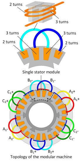
Figure 1a illustrates the topology of the proposed modular PMSM. For a comparison, the 12-slot/10-pole conventional modular PMSM with DTP-FSCW is also given in Figure 1b. It is obvious in Figure 1a that the proposed machine is a 24-slot/10-pole machine with a special DTP-TSPW winding. The DTP-TSPW employed in the proposed machine consists of two 12-slot/10-pole single-layer FSCWs (named Winding-I and Winding-II), which are overlapped by half of the coil pitch. Therefore, there are six stator teeth of the proposed machine that are not covered by the end winding. The modularity of the stator of the proposed machine can be conducted by splitting those six uncovered stator teeth, thereby obtaining six identical stator modules while the conventional 12-slot/10-pole machine with DTP-FSCW can be divided into twelve modules. A stator module of the proposed machine is outlined and shown individually in Figure 1a. Obviously, each stator module of the proposed machine contains two overlapped coils and each coil side occupies a whole stator slot. The six stator modules of the proposed machine are fixed on the stator frame by dovetails. The stator frame is made of nonmagnetic material to avoid extra iron loss.
The most distinctive feature of the proposed machine is the employment of the winding coils with different turns per coil side (denoted by N1 and N2 respectively as indicated in Figure 1a). This type of coil was introduced and described in [23,24]. It can be realized by arranging the in-turn and out-turn on the same coil side, which is 3-dimensionally illustrated in Figure 1a. Thus, the turn difference between the two coil sides of this kind of coil has to be 1 [24], as expressed by
Due to the special structure of this type of coil, the number of coil turns needs to be specifically defined as
According to (2), the number of coil turns of this type of coil is definitely a fraction because of the unequal turns per coil side. To accommodate this type of coil, the stator slots with different slot depths are employed in the proposed machine.
The selection of the coil side turns (N1 and N2) of the proposed machine impacts enormously on the harmonics of the winding MMF. Proper coil side turns with reasonable magnetic circuit design considerably reduce the nonworking space subharmonic and slot-harmonic content and it is discussed in detail based on the winding MMF analysis in the following section.
3. Winding MMF and Winding Factors
In this section, the winding MMF and winding factors of the proposed machine are analytically calculated. On this basis, the optimal coil side turns (N1 and N2) are determined. Due to the employment of the coils with different turns per coil side, Winding-I and Winding-II are mirror images rather than shifting images, which means that the stator shifting theory cannot be directly applied to the proposed machine. Hence, both MMFs of the two groups of windings need to be derived separately, and the MMF function of the entire winding (referred to as resultant winding MMF) of the proposed machine can be subsequently obtained by adding them together.
The winding MMF can be calculated by adding the corresponding coil side MMFs. In Figure 1a, the coil sides of the proposed machine are numbered in consecutive order, so that their MMF vectors can be denoted by V1, V2, V3, etc. The phase currents of the total six phases of the proposed machine can be expressed as
where Im denotes the phase current amplitude, and φ is the difference in current phase between the two groups of windings. Accordingly, the coil side MMF vectors belonging to phase A1 and phase A2 of the proposed machine can be obtained, as tabulated in Table 1. It should be emphasized that the different harmonic orders (denoted by ν) and winding directions of the coils are taken into account when calculating the vectors.
3.1. MMF of Winding-I
According to Table 1, the MMF generated by phase A1 can be expressed in the function form [36], as shown below.
where x denotes the position angle on the air gap circle, and is introduced to denote the amplitude of the MMF generated by phase A1, which is a standing wave as expected. The specific expression of is also presented in (4). Based on the temporal and spatial relation among phase A1, phase B1 and phase C1 (symmetric three phases), the MMF function of Winding-I can be directly obtained [24], which is expressed as
3.2. MMF of Winding-II
The derivation process of the MMF function of Winding-II is the same as that of Winding-I. First, the function form of the MMF of phase A2 should be derived [36], which is expressed as
It can be noted that βν in (6) is exactly the inverse number of αν in (4), that is
Thus, the MMF amplitudes of phase A1 always equals that of phase A2, that is
This conclusion is natural because Winding-I and Winding-II are mirror images as mentioned previously. Although the amplitudes of phase MMFs of the two groups of windings are equal, they are still denoted individually in the following derivation to distinguish them.
Back to the MMF analysis of Winding-II, the MMF of Winding-II can also be directly obtained based on (6) [24], which is expressed as
3.3. MMF of the Entire Winding
The resultant MMF of the entire winding of the proposed machine can be achieved by adding the MMFs of Winding-I and Winding-II, which are expressed by (5) and (9), respectively. Through some mathematical manipulations, the resultant winding MMF of the proposed machine can be expressed as
Note that 0/0 is defined as 1 when calculating αν, βν, Aν and Bν presented above.
3.4. Winding Factor
Winding-I and Winding-II share the same phase winding factor (PWF) because their MMF amplitudes are equal, as pointed out in Section 3.2. According to the definition of PWF [37], the PWF of the proposed machine can be obtained as
The PWF characterizes the utilization of the currents in forming the phase MMF. If the PWF of a certain harmonic component is 0, this harmonic component does not exist in the MMF of the corresponding phase winding.
In addition to PWF, comprehensive winding factor (CWF) is employed to describe the resultant MMF. According to the definition of CWF [35], the CWF of the proposed machine can be derived as
The CWF characterizes the utilization of the currents in forming the resultant MMF of the entire winding. Naturally, if the CWF of a certain harmonic is 0, the resultant MMF does not contain this harmonic component.
3.5. Selection of Coil Side Turns
As mentioned in Section 2, the coil side turns greatly influence the winding MMF of the proposed machine, which has been confirmed by the winding MMF analysis above. In this section, the coil side turns are optimally selected to improve the electromagnetic performance of the machine.
Before searching for the appropriate coil side turns, the current phase difference φ defined in (3) needs to be determined. To promote the torque density as much as possible, the 5th harmonics (working harmonic) of the two groups of windings should be in phase. By referring to (5) and (9), φ should be selected as
Thus, the variation of φ with the ratio of N1 to N2 can be obtained, as shown in Figure 2. It is obvious in Figure 2 that φ monotonically decreases with the increase of N1/N2. In fact, the value of φ calculated by (13) is exactly the phase difference between the two three-phase systems in the proposed machine, as illustrated in Figure 3.
According to the resultant winding MMF function expressed by (10), attached with the constraint of (13), the mapping relations between various winding MMF harmonics and the value of N1/N2 can be determined. Figure 4 presents the variations of the 1st, 5th and 7th winding MMF harmonics with N1/N2. As shown in Figure 4, the 5th harmonic (working harmonic) varies little with N1/N2, which means that the value of N1/N2 has little impact on the torque density of the proposed machine. As for nonworking harmonics, it is obvious that the 1st harmonic is sensitive to N1/N2, and it almost disappears when N1/N2 equals 0.6. In contrast, the 7th harmonic is always eliminated no matter what the value of N1/N2 is. Since the 1st and 7th harmonics contribute a lot to the nonworking space harmonic content in 12-slot/10-pole FSCW, the optimal value of N1/N2 should be 0.6 for the lowest nonworking space harmonic content, as pointed out in Figure 4. In this case, the corresponding value of φ should be 82.665° according to (13).
With the determination of N1/N2 and φ, both PWF and CWF of the proposed machine can be exactly calculated, and are tabulated in Table 2, together with those of the conventional 12-slot/10-pole PMSM with DTP-FSCW. On this basis, the resultant winding MMF spectra of the two machines can be obtained and are presented in Figure 5. It indicates that the working harmonics (the 5th harmonics) in the winding MMFs of the two machines are almost equal because their CWFs of the working harmonics are quite close, as presented in Table 2. In terms of the nonworking space harmonics, both two machines perform well in suppressing the subharmonics. Only a small amount of the 1st winding MMF harmonic exists in the proposed machine, while it is completely removed in the conventional one. However, the two machines exhibit vastly different content of higher order nonworking harmonics. The proposed machine eliminates the 7th and 17th winding MMF harmonics, which are quite high in the conventional one because they are exactly the slot-harmonics in 12-slot/10-pole machines.
Although the optimal value of N1/N2 is 0.6, it cannot be fully realized only by employing the coil with unequal turns per coil side because of the constraint expressed by (1). As indicated in Figure 4, the approximate solution to the optimal coil side turns is
Obviously, there is a small gap between this approximate solution and the optimal point, as pointed out in Figure 4. Specifically, it would be better if N1 becomes slightly smaller to reach the optimal value of N1/N2 (0.6). This gap can be filled by using the stator core with nonuniformly distributed yoke thickness, which is illustrated in Figure 6. hy1 and hy2 denote the thicknesses of the stator yoke below the stator slots containing N1-turn and N2-turn coil sides, respectively. hy1 is designed to be smaller than hy2, that is hy1 < hy2. In this way, the reluctances of the magnetic paths indicated by the red symbols in Figure 6 are increased because of the magnetic saturation so that the turn number of the N1-turn side is equivalently reduced. The selection of hy1 and hy2 should be conducted with a specific machine design case, which is presented in Section 4.
4. Electromagnetic Characteristics
In this section, two outer rotor surface PM (SPM) machines are employed to evaluate the electromagnetic characteristics of the proposed and conventional modular PMSMs, whose basic topologies have been illustrated in Figure 1. Table 3 tabulates the key parameters of these two machines. To make the rated current and voltage within the proper ranges, the turns in series per phase of the proposed machine is set to be 50, which can be realized by connecting 10 groups of the winding of the proposed machine in series. As pointed out in Section 3.5, two different stator yoke thicknesses (hy1 and hy2) are employed in the proposed machine to ensure that its winding works with the equivalently optimal coil side turns. As clarified in Section 3.5, φ should be 82.665° when the coil side turns are optimized, which can be observed through the phase difference between the EMFs of the two groups of windings in the proposed machine, as shown in Figure 7. Naturally, the optimal value of hy1 is 7.755 mm, as indicated in Figure 7. Figure 8 presents the sections of the two compared machines.
4.1. No-Load Back EMF
The no-load back EMF waves of the two compared machines and their harmonic distributions are presented in Figure 9 and Figure 10, respectively. It is noteworthy in Figure 10 that the fundamental component of the EMF of the proposed machine is slightly lower than that of the conventional one. It is caused by the small value of hy1 as explained previously.
4.2. Cogging Torque
The cogging torque waves of the two machines are presented in Figure 11. Obviously, the peak to peak value of the cogging torque of the proposed machine is substantially lower than that of the conventional one. It is mainly because the proposed machine has a larger least common multiple of the stator slot number and pole number than the conventional one.
4.3. Armature Reaction Field
The armature reaction fields of the two compared machines supplied with the rated phase currents are calculated by using the frozen permeability method and presented in Figure 12. In addition, Figure 13 and Figure 14 present the corresponding air gap flux densities and their spectra, respectively. Both Figure 12 and Figure 13 indicate that the periodicity of the of the armature reaction field of the proposed machine is more plainly visible (5 cycles) than that of the conventional one. This is because the proposed machine exhibits lower nonworking harmonic content in the armature reaction field than the conventional one. As shown in Figure 14, the 1st, 7th and 17th harmonics of the armature reaction fields are effectively reduced in the proposed machine. Conversely, the armature reaction field of the conventional machine is distorted mainly due to its high content of the 7th and 17th harmonics.
In fact, the spectra of the armature reaction fields in Figure 14 are in good agreement with those of the winding MMFs in Figure 5, which verifies the winding MMF analysis presented in Section 3. However, due to the magnetic field modulation effect of the stator slots, there are some slight differences between them.
4.4. On-Load Torque
The on-load torque waves of the two machines at the rated working condition (presented at the bottom of Table 3) are shown in Figure 15. Both machines are driven by using the control strategy of id = 0 (id denotes the d-axis current). For convenient comparison, the main on-load torque performance items are summarized in Table 4. It can be seen from Table 4 that the proposed machine produces a slightly higher average torque than the conventional one, which should be attributed to its low space harmonic content. Moreover, the proposed machine exhibits lower torque ripple than the conventional one, owing to its low cogging torque. Overall, the proposed machine performs better in torque performance than the conventional machine.
4.5. Loss and Efficiency
The losses of the two machines are calculated still at the rated working condition. It is known that rotor loss is more sensitive to the space harmonics than losses in other parts of the machine. Figure 16 illustrates the rotor losses of the two machines. The no-load rotor losses of the two machines are specially set to be close to examine the effect of the space harmonic content on the rotor loss. When the two machines are on-load, the difference between their rotor losses becomes apparent. The total on-load rotor loss of the proposed machine is 47.13% lower than that of the conventional one owing to the lower nonworking space harmonic content.
Apart from rotor loss, the losses in other parts of the machine are also calculated to obtain the efficiencies of the two compared machines, as summarized in Table 5. The stator core loss of the proposed machine is lower than that of the conventional one, but the difference is not large because the stator core loss is mainly induced by the rotor PM magnetic field. The stator frame losses of both machines are so small that they can almost be ignored because the stator frames are made of nonmagnetic material (austenitic stainless steel), which prevents the magnetic flux from passing through it. To include the end winding loss in the copper loss, the conductor lengths of the two machines are calculated, as presented in Figure 17, according to the geometric model used in [25]. It should be clarified that the conductor length of the proposed machine is averaged due to the employment of the coils with different turns per coil side. As shown in Figure 17, the conductor length of the proposed machine is 11.53% higher than that of the conventional one due to the overlapped end winding. As expected, the proposed machine has a higher copper loss because of its longer end winding. In spite of this, the efficiency of the proposed machine is still more than 2% higher than that of the conventional one because of the much lower rotor loss.
4.6. Power Factor
The on-load voltage and input current waves of the two compared machines are presented in Figure 18, based on which the power factors of the two machines can be calculated. The proposed machine has a higher power factor (0.9835) than the conventional one (0.9627) at the rated working condition. This is because the low space harmonic content reduces the winding inductance of the proposed machine.
5. Conclusions
This paper proposes a modular PMSM with low space harmonic content. The employment of the special DTP-TSPW in the proposed machine allows its stator to be divided into six modules. The theoretical analysis and FEM simulation show that the proposed modular machine exhibits much lower nonworking space harmonic content than the modular PMSMs with the conventional FSCWs, which brings the advantage of higher efficiency in spite of its longer end winding due to the overlapped coils. In addition, the power factor of the proposed machine can also be increased owing to the low nonworking space harmonic content.
Author Contributions
Conceptualization, K.W. and H.L.; methodology, K.W. and H.L.; software, K.W.; validation, K.W.; formal analysis, K.W.; investigation, K.W. and H.L.; resources, K.W. and H.L.; data curation, K.W.; writing—original draft preparation, K.W.; writing—review and editing, K.W. and H.L.; visualization, K.W.; supervision, H.L.; project administration, H.L.; funding acquisition, H.L. All authors have read and agreed to the published version of the manuscript.
Funding
This research was funded by Postgraduate Research & Practice Innovation Program of Jiangsu Province, grant number KYCX17_0086 and Special Plan of Major Scientific and Technological Achievements Transformation of Jiangsu Province, grant number BA2015141.
Conflicts of Interest
The authors declare no conflict of interest. The funders specified the industrial demand and agreed to publish the achievements and results of this study.
References
- Bang, D.J.; Polinder, H.; Shrestha, G.; Abraham Ferreira, J. Promising directdrive generator system for large wind turbines. EPE J. 2008, 18, 7–13. [Google Scholar] [CrossRef]
- Fornasiero, E.; Alberti, L.; Bianchi, N.; Bolognani, S. Considerations on selecting fractional-slot nonoverlapped coil windings. IEEE Trans. Ind. Appl. 2013, 49, 1316–1324. [Google Scholar] [CrossRef]
- EL-Refaie, A.M. Fractional-slot concentrated-windings synchronous permanent magnet machines: Opportunities and challenges. IEEE Trans. Ind. Electron. 2010, 57, 107–121. [Google Scholar] [CrossRef]
- Bianchi, N.; Bolognani, S.; Pre, M.D.; Grezzani, G. Design considerations for fractional-slot winding configurations of synchronous machines. IEEE Trans. Ind. Appl. 2006, 42, 997–1006. [Google Scholar] [CrossRef]
- Jussila, H.; Salminen, P.; Niemela, M.; Pyrhonen, J. Guidelines for designing concentrated winding fractional slot permanent magnet machines. In Proceedings of the IEEE International Conference on Power Engineering, Energy and Electrical Drives, Setubal, Portugal, 12–14 April 2007. [Google Scholar]
- Bianchi, N.; Dai Pre, M. Use of the star of slots in designing fractional-slot single-layer synchronous motors. IEE Electr. Power. Appl. 2006, 153, 459–466. [Google Scholar] [CrossRef]
- Atallah, K.; Howe, D.; Mellor, P.H.; Stone, D.A. Rotor loss in permanent-magnet brushless AC machines. IEEE Trans. Ind. Appl. 2000, 36, 1612–1618. [Google Scholar]
- Bianchi, N.; Bolognani, S.; Fornasiero, E. An overview of rotor losses determination in three-phase fractional-slot PM machines. IEEE Trans. Ind. Appl. 2010, 46, 2338–2345. [Google Scholar] [CrossRef]
- Bianchi, N.; Fornasiero, E. Impact of MMF space harmonic on rotor losses in fractional-slot permanent-magnet machines. IEEE Trans. Energy Convers. 2009, 24, 323–328. [Google Scholar] [CrossRef]
- Fornasiero, E.; Bianchi, N.; Bolognani, S. Slot harmonic impact on rotor losses in fractional-slot permanent-magnet machines. IEEE Trans. Ind. Electron. 2012, 59, 2557–2564. [Google Scholar] [CrossRef]
- Dajaku, G.; Gerling, D. A novel 12-teeth/10-poles PM machine with flux barriers in stator yoke. In Proceedings of the International Conference on Electrical Machines, Marseille, France, 2–5 September 2012. [Google Scholar]
- Dajaku, G.; Xie, W.; Gerling, D. Reduction of low space harmonics for the fractional slot concentrated windings using a novel stator design. IEEE Trans. Magn. 2014, 50, 1–12. [Google Scholar] [CrossRef]
- Dajaku, G.; Gerling, D. Low costs and high-efficiency electric machines. In Proceedings of the International Electric Drives Production Conference, Nuremberg, Germany, 15–18 October 2012. [Google Scholar]
- Wang, Y.; Qu, R.; Wu, L.; Fang, H.; Li, D. Reduction of sub-harmonic effect on the fractional slot concentrated winding interior PM machines by using spoke-type magnets. In Proceedings of the International Electric Machines & Drives Conference, Coeur d’Alene, IL, USA, 10–13 May 2015. [Google Scholar]
- Alberti, L.; Fornasiero, E.; Bianchi, N. Impact of the rotor yoke geometry on rotor losses in permanent-magnet machines. IEEE Trans. Ind. Appl. 2012, 48, 98–105. [Google Scholar] [CrossRef]
- Choi, G.; Jahns, T.M. Reduction of eddy-current losses in fractional-slot concentrated-winding synchronous PM machines. IEEE Trans. Magn. 2016, 52, 1–4. [Google Scholar] [CrossRef]
- Wu, L.; Qu, R.; Li, D. Reduction of rotor eddy-current losses for surface PM machines with fractional slot concentrated windings and retaining sleeve. IEEE Trans. Magn. 2014, 50, 1–4. [Google Scholar] [CrossRef]
- Abdel-Khalik, A.S.; Ahmed, S.; Massoud, A.M. Low space harmonics cancelation in double-layer fractional slot winding using dual multiphase winding. IEEE Trans. Magn. 2015, 51, 1–10. [Google Scholar] [CrossRef]
- Alberti, L.; Bianchi, N. Theory and design of fractional-slot multilayer windings. In Proceedings of the Energy Conversion Congress & Exposition, Phoenix, AZ, USA, 17–22 September 2011. [Google Scholar]
- Cistelecan, M.V.; Ferreira, F.J.T.E.; Popescu, M. Three phase tooth-concentrated multiple-layer fractional windings with low space harmonic content. In Proceedings of the Energy Conversion Congress & Exposition, Atlanta, GA, USA, 12–16 September 2010. [Google Scholar]
- Reddy, P.B.; EL-Refaie, A.M.; Huh, K. Effect of number of layers on performance of fractional-slot concentrated-windings interior permanent magnet machines. IEEE Trans. Power Electron. 2015, 30, 2205–2218. [Google Scholar] [CrossRef]
- Sun, A.; Li, J.; Qu, R.; Li, D. Effect of multilayer windings on rotor losses of interior permanent magnet generator with fractional-slot concentrated-windings. IEEE Trans. Magn. 2014, 50, 1–4. [Google Scholar] [CrossRef]
- Dajaku, G. Elektrische Maschine. German Patent DE 102008 057349 B3, 15 July 2010. [Google Scholar]
- Dajaku, G.; Gerling, D. Eddy current loss minimization in rotor magnets of PM machines using high-efficiency 12-teeth/10-slots winding topology. In Proceedings of the International Conference on Electrical Machines & Systems, Beijing, China, 20–23 August 2011. [Google Scholar]
- Wang, K.; Zhu, Z.Q.; Ombach, G. Synthesis of high performance fractional-slot permanent-magnet machines with coil-pitch of two slot-pitches. IEEE Trans. Energy Convers. 2014, 29, 758–770. [Google Scholar] [CrossRef]
- Yue, Y.; Wu, L.; Jia, S. Comparison of IPM machines with fractional-slot concentrated windings and coil-pitch of two slot-pitches windings for EV application. In Proceedings of the International Conference on Electrical Machines & Systems, Jeju, South Korea, 7–10 October 2018. [Google Scholar]
- Wang, J.; Patel, V.I.; Wang, W. Fractional-slot permanent magnet brushless machines with low space harmonic contents. IEEE Trans. Magn. 2014, 50, 1–9. [Google Scholar] [CrossRef]
- Reddy, P.B.; Huh, K.; EL-Refaie, A.M. Generalized approach of stator shifting in interior permanent-magnet machines equipped with fractional-slot concentrated windings. IEEE Trans. Ind. Electron. 2014, 61, 5035–5046. [Google Scholar] [CrossRef]
- Patel, V.I.; Wang, J.; Wang, W.; Chen, X. Six-phase fractional-slot-per-pole-per-phase permanent-magnet machines with low space harmonics for electric vehicle application. IEEE Trans. Ind. Appl. 2014, 50, 2554–2563. [Google Scholar] [CrossRef] [Green Version]
- Abdel-Khalik, A.S.; Ahmed, S.; Massoud, A.M. A six-phase 24-slot/10-pole permanent-magnet machine with low space harmonics for electric vehicle applications. IEEE Trans. Magn. 2016, 52, 1–10. [Google Scholar] [CrossRef]
- Harke, M. Design of fractional slot windings with coil span of two slots for use in six-phase synchronous machines. J. Eng. 2019, 2019, 4391–4395. [Google Scholar] [CrossRef]
- Dajaku, G.; Gerling, D. A novel 24-slots/10-poles winding topology for electric machines. In Proceedings of the International Electric Machines & Drives Conference, Niagara Falls, ON, Canada, 15–18 May 2011. [Google Scholar]
- Harke, M. Fractional slot windings with a coil span of two slots and less content of low order harmonics. In Proceedings of the International Symposium on Power Electronics, Electrical Drives, Automation and Motion, Amalfi, Italy, 20–22 June 2018. [Google Scholar]
- Sun, H.Y.; Wang, K. Space harmonics elimination for fractional-slot windings with two-slot coil pitch. IEEE Access 2019, 7, 106961–106972. [Google Scholar] [CrossRef]
- Wang, K.; Lin, H. A novel 24-slot/10-pole dual three-phase fractional-slot overlapped winding for low non-working space harmonics and stator modularization. IEEE Access 2020, 8, 85490–85503. [Google Scholar] [CrossRef]
- Tang, N.; Brown, I.P. Framework and solution techniques for suppressing electric machine winding MMF space harmonics by varying slot distribution and coil turns. IEEE Trans. Magn. 2018, 54, 1–12. [Google Scholar] [CrossRef]
- Raziee, S.M.; Misir, O.; Ponick, B. Winding function approach for winding analysis. IEEE Trans. Magn. 2017, 53, 1–9. [Google Scholar] [CrossRef]
Figure 1.
Machine topologies. (a) Proposed modular machine with special dual three-phase two-slot pitch winding (DTP-TSPW); (b) conventional modular machine with DTP-fractional-slot concentrated winding (FSCW).
Figure 1.
Machine topologies. (a) Proposed modular machine with special dual three-phase two-slot pitch winding (DTP-TSPW); (b) conventional modular machine with DTP-fractional-slot concentrated winding (FSCW).

Figure 2.
Variation of φ with N1/N2.

Figure 3.
Phase diagram of the proposed machine.

Figure 4.
Variations of winding MMF harmonics of the proposed machine with N1/N2.

Figure 5.
Winding MMF harmonics (N1/N2 = 0.6 for the winding of the proposed machine).

Figure 6.
Main circuit of the magnetic flux generated by the coil sides with N1 turns of the proposed machine.
Figure 6.
Main circuit of the magnetic flux generated by the coil sides with N1 turns of the proposed machine.

Figure 7.
Variation of the phase difference between the electromotive forces (EMFs) of the two groups of windings in the proposed machine with hy1 (hy2 = 9 mm constantly).
Figure 7.
Variation of the phase difference between the electromotive forces (EMFs) of the two groups of windings in the proposed machine with hy1 (hy2 = 9 mm constantly).

Figure 8.
Machine sections: (a) proposed machine; (b) conventional machine.

Figure 9.
No-load back EMF waves: (a) proposed machine; (b) conventional machine.

Figure 10.
Spectra of the no-load back EMFs of the two compared machines.

Figure 11.
Cogging torques.

Figure 12.
Armature reaction fields: (a) proposed machine, (b) conventional machine.

Figure 13.
Air gap flux densities of the armature reaction fields of the two compared machines.

Figure 14.
Spectra of the air gap flux densities of the armature reaction fields of the two compared machines.
Figure 14.
Spectra of the air gap flux densities of the armature reaction fields of the two compared machines.

Figure 15.
On-load torque waves of the two compared machines.

Figure 16.
Rotor losses of the two compared machines.

Figure 17.
Conductor lengths.

Figure 18.
On-load voltage and input current waves: (a) proposed machine, (b) conventional machine.


Table 1.
Coil side magnetomotive force (MMF) vectors of phase A1 and phase A2 of the proposed machine.
Table 1.
Coil side magnetomotive force (MMF) vectors of phase A1 and phase A2 of the proposed machine.
| Coil Side MMF Vector | Modulus | Angle | |
|---|---|---|---|
| Phase A1 | V1 | 0 | |
| V13 | |||
| V15 | |||
| V3 | |||
| Phase A2 | V16 | ||
| V4 | |||
| V2 | |||
| V14 |
Table 2.
Winding factors of the two compared machines.
| Harmonic Order | Proposed Machine | Conventional Machine | ||
|---|---|---|---|---|
| 1 | 0.354 | 0.0114 | 0.259 | 0 |
| 2 | 0 | 0 | 0 | 0 |
| 3 | 0.729 | 0 | 0.707 | 0 |
| 4 | 0 | 0 | 0 | 0 |
| 5 | 0.968 | 0.968 | 0.966 | 0.966 |
| 6 | 0 | 0 | 0 | 0 |
| 7 | 0.968 | 0 | 0.966 | 0.966 |
| 8 | 0 | 0 | 0 | 0 |
| 9 | 0.729 | 0 | 0.707 | 0 |
| 10 | 0 | 0 | 0 | 0 |
| 11 | 0.354 | 0.354 | 0.259 | 0 |
| 12 | 0 | 0 | 0 | 0 |
| 13 | 0.354 | 0.354 | 0.259 | 0 |
| 14 | 0 | 0 | 0 | 0 |
| 15 | 0.729 | 0 | 0.707 | 0 |
| 16 | 0 | 0 | 0 | 0 |
| 17 | 0.968 | 0 | 0.966 | 0.966 |
| 18 | 0 | 0 | 0 | 0 |
| 19 | 0.968 | 0.968 | 0.966 | 0.966 |
Table 3.
Key parameters of the two compared machines.
| Proposed Machine | Conventional Machine | |
|---|---|---|
| Stator slot number | 24 | 12 |
| Rotor pole number | 10 | |
| Stator outer diameter (mm) | 150 | |
| Stator yoke thickness (mm) | hy1 = 7.755, hy2 = 9 | 9 |
| Stator slot opening width (mm) | 3.5 | 4.8 |
| Air gap length (mm) | 0.5 | |
| PM thickness (mm) | 2 | |
| Pole arc coefficient | 0.694 | |
| Rotor core thickness (mm) | 15 | |
| Active length (mm) | 40 | |
| Number of turns in series per phase | 50 | |
| Number of parallel branches | 1 | |
| PM material | N42SH | |
| Stator core material | 50JNE470 | |
| Rotor core material | Solid steel | |
| Stator frame material | Austenitic stainless steel | |
| Rated speed (rpm) | 2400 | |
| Rated phase current in RMS value (A) | 15 | |
Table 4.
On-load torque performance items.
| Proposed Machine | Conventional Machine | |
|---|---|---|
| Average torque (Nm) | 15.50 | 15.18 |
| Torque ripple | 10.70% | 12.39% |
Table 5.
Losses and efficiencies of the two compared machines.
| Proposed Machine | Conventional Machine | |
|---|---|---|
| Stator core loss (W) | 111.51 | 119.1 |
| Stator frame loss (W) | 0.59 | 0.82 |
| Copper loss (W) | 32.38 | 29.03 |
| PM loss (W) | 25 | 31.6 |
| Rotor core loss (W) | 42.37 | 111.33 |
| Total loss (W) | 211.85 | 291.88 |
| Output power (W) | 3895.57 | 3815.15 |
| Efficiency | 94.56% | 92.35% |
© 2020 by the authors. Licensee MDPI, Basel, Switzerland. This article is an open access article distributed under the terms and conditions of the Creative Commons Attribution (CC BY) license (http://creativecommons.org/licenses/by/4.0/).
Share and Cite
MDPI and ACS Style
Wang, K.; Lin, H. Modular Permanent Magnet Synchronous Machine with Low Space Harmonic Content. Energies 2020, 13, 3924. https://doi.org/10.3390/en13153924
AMA Style
Wang K, Lin H. Modular Permanent Magnet Synchronous Machine with Low Space Harmonic Content. Energies. 2020; 13(15):3924. https://doi.org/10.3390/en13153924
Chicago/Turabian StyleWang, Keyi, and Heyun Lin. 2020. "Modular Permanent Magnet Synchronous Machine with Low Space Harmonic Content" Energies 13, no. 15: 3924. https://doi.org/10.3390/en13153924
Note that from the first issue of 2016, this journal uses article numbers instead of page numbers. See further details here.