A Comprehensive Review on Grid Connected Photovoltaic Inverters, Their Modulation Techniques, and Control Strategies


College of Energy and Electrical Engineering, Hohai University, Nanjing 211100, China
*
Author to whom correspondence should be addressed.
Energies 2020, 13(16), 4185; https://doi.org/10.3390/en13164185
Submission received: 16 June 2020
/
Revised: 29 July 2020
/
Accepted: 10 August 2020
/
Published: 13 August 2020
(This article belongs to the Section D1: Advanced Energy Materials)
Abstract
:The installation of photovoltaic (PV) system for electrical power generation has gained a substantial interest in the power system for clean and green energy. However, having the intermittent characteristics of photovoltaic, its integration with the power system may cause certain uncertainties (voltage fluctuations, harmonics in output waveforms, etc.) leading towards reliability and stability issues. In PV systems, the power electronics play a significant role in energy harvesting and integration of grid-friendly power systems. Therefore, the reliability, efficiency, and cost-effectiveness of power converters are of main concern in the system design and are mainly dependent on the applied control strategy. This review article presents a comprehensive review on the grid-connected PV systems. A wide spectrum of different classifications and configurations of grid-connected inverters is presented. Different multi-level inverter topologies along with the modulation techniques are classified into many types and are elaborated in detail. Moreover, different control reference frames used in inverters are presented. In addition, different control strategies applied to inverters are discussed and a concise summary of the related literature review is presented in tabulated form. Finally, the scope of the research is briefly discussed.
1. Introduction
Renewable energy (RE) plays a pivotal role in supporting the power system to meet the ever-increasing load demand. Among the renewable energy resources (RES), photovoltaic (PV) power units are gaining more interest due to (a) clean and emission free energy, (b) simple access, and (c) high return on investment [1]. Up to the year 2009, the majority of PV installations were made at a small level and were only connected to the distribution level. However, when the USA installed the first transmission level (230 kV) PV system in Florida [2], it drew the world’s attention. Therefore, the interest in large scale PV installation (transmission and sub-transmission levels) increased rapidly and as a result, globally the installed capacity of PV reached 505 GW by the end of 2018. The total installed capacity of PV from 2008–2018 is presented in Figure 1. The figure shows a dramatic increase in PV installation as in 2008 the installed capacity is 15 GW, and it increases to 505 GW at the end of 2018 [3].
Depending on the conversion system, two types of configuration systems are used for grid-connected PV power plants (GCPPPs), i.e., single and two stage conversion/configuration systems. A configuration is said to be a single stage, when there is a direct connection between the inverter input side and the PV array and is then connected to the grid through the transformer as depicted in Figure 2a [4]. On the contrary, if a DC–DC converter is utilized to integrate the PV array with the inverter’s input side then the configuration is said to be a two stage as presented in Figure 2b [4]. It shows that in both configuration systems, inverter plays a significant role in integration and
DC to AC inversion. Therefore, for this purpose different inverter topologies were designed by researchers. Among these topologies, a conventional 2-level inverter topology is very popular and widely used for small scale applications. However, this inverter is not appropriate for medium and large-scale applications as it suffers from high voltage stresses and high thermal losses that significantly decrease the efficiency of the system [5]. To overcome these problems, multilevel inverter (MLI) topologies were introduced for GCPPPs as they have the ability to provide good quality output waveforms with low harmonic distortion, lower stress on switches, a lesser requirement of passive filter, and require less maintenance [6,7,8]. The MLIs are classified into various types based on the power circuitry structure such as reduced switch [9,10], asymmetric [11], modular [12], and hybrid [13,14], etc. The quality of output waveforms of MLIs greatly depends on the modulation technique (MT) applied to the switches (metal oxide silicon field effect transistor, insulated gate bipolar transistor, etc.). The main tasks of MTs are to control and enhance the output waveforms and to minimize the total harmonic distortion (THD) as well as switching losses. Based on switching frequency the MTs are classified into high switching frequency (HSF) [15,16] and fundamental switching frequency (FSF) [17]. Both types of modulation techniques are further classified into various types that will be discussed later in this article in detail.
Due to the stochastic and unpredictable nature of PV, the functionality of the grid-connected inverters (GCIs) is not only limited to DC–AC conversion, but also has to provide various intelligent and ancillary services such as voltage regulation, frequency regulation, etc. [18]. As the operation of GCPPPs mainly depends on the control algorithm applied to the GCIs, the design of the controller is of main consideration and can therefore be categorized into two main segments. (1) Input (DC) side controller: the main responsibility of this controller is to extract or get the maximum available power from the PV source by applying a maximum power point tracking (MPPT) algorithm [19]. (2) Grid (system) side controller: the system side controller must have the ability to perform many functions such as (a) grid synchronization, (b) control of reactive (Q) and active power (P), (c) control of DC-link voltage, and (d) injection of high-quality power [20,21]. In addition to these services, the grid operator may also demand intelligent services such as voltage regulation and harmonic compensation etc. [22].
In this article, the authors aim is to provide a comprehensive review on PV systems. Different classifications of GCIs are discussed, and the comparative study of current and voltage source inverters are presented in a table form. Moreover, the features, advantages, and disadvantages of four different PV inverter configurations are discussed and presented. A basic circuitry and a detailed analysis of the most commonly used grid-connected multi-level inverter (GCMLI) topologies and their MTs are elaborated. Furthermore, different characteristics such as MT, switching frequency, and capacity, etc., of numerous related scientific articles on MLI topologies are presented in the table. A detailed analysis of two main types of modulation techniques and their subtypes is elaborated in detail. Later, different control structures and controller types that are applied to grid-connected inverters are thoroughly demonstrated. The important characteristics (reference frame, modulation technique, controller type, etc.) of different scientific articles are presented in table. The scope and trends of this research are broadly discussed later. The main contributions of the proposed review article are summarized and critically compared and associated with the other review papers already published in literature as shown in Table 1.
The remaining parts of the article are constructed as follows: Different classifications and configuration of GCIs are explained in Section 2 and Section 3 respectively. Detailed analyses of grid-connected multi-level inverter (GCMLI) topologies under different descriptions are elaborated in Section 4. Various types of modulation techniques used to drive the switches are presented in Section 5. Various control reference frames used in 3-Φ GCPPPS are discussed in Section 6. In Section 7, the control strategies applied in different reference frames are presented. The scope of this research is carried out in Section 8. Lastly, a brief summary of this paper is concluded in Section 9.
2. Classification of Inverters
An inverter plays a very prominent role in grid-synchronization and is responsible for DC–AC inversion [35]. Inverters are generally categorized into line commutation inverters (LCI) and self commutation inverters (SCI) based on the commutation process (turned ON and turned OFF behavior). A detailed taxonomy tree of the inverter classification is presented in Figure 3. A figure shows that SCIs are further divided into current source (CSI) and voltage source inverter (VSI). Moreover, VSIs are further divided on the bases for their conduction mode (CM) into current CM (CCM) and voltage CM (VCM). The different classification of inverters is explained through a taxonomy tree in detail in this section [36].
2.1. Line Commutated Inverter
Generally, in LCIs semi-controlled semiconductor devices such as thyristors are used as switches. In semi-controlled switches, the turn ON operation is controlled through the gate terminal whereas the turn OFF characteristics of the switches depends on the circuit parameters i.e., direction of current or voltage polarity. Therefore, in LCI a forced commutation is required to turn OFF the switches. For this purpose, different approaches are presented such as in case of half-bridge LCI an antiparallel diode is attached to enable the force commutation process (to turn OFF the switch) [37].
2.2. Self Commutated Inverter
A MOSFET or IGBT devices are usually used in SCI. MOSFETs are used for high frequency (20–800 kHz) applications having power ratings less than 20 kW. On the contrary, IGBTs are used for low frequency (20 kHz) applications having power ratings greater than 100 kW. The commutation operations of these switches are fully controlled through the gate terminal [38]. Therefore, it controls both the current and voltage output waveforms. High switching frequency devices are preferably used in grid-connected applications to reduce the inverter weight, filter size, and output waveform harmonics [39]. Moreover, SCI improves the grid power factor, suppresses the current harmonics, and shows high robustness to the grid disturbances. Due to the development of sophisticated switching devices and improvement in the control strategies, SCIs are preferably used as compared to LCI. The SCIs are further classified into current source inverter (CSI) and voltage source inverter (VSI).
2.2.1. Current Source Inverter
In CSI, a DC current source is connected as an input to the inverter; hence, the input current polarity remains the same. Therefore, the power flow direction is determined by the input DC voltage polarity. The current waveforms obtained at the output side of CSI are constant in amplitude but variable in width. The main disadvantage of using CSI is the utilization of a large inductor that is connected in series with the input side to handle the current stability issue [40]. The usage of an inductor makes the circuitry less efficient, bulky, and expensive [20].
2.2.2. Voltage Source Inverter
A DC voltage source is connected as an input to the VSI, hence the input voltage polarity remains the same. Therefore, the direction of input current determines the direction of power flow. The waveforms of an output AC voltage are constant in amplitude but variable in width. Moreover, a major drawback associated with VSI is the usage of a large capacitor that is connected in parallel with the input source [40]. The VSIs are preferably used in grid-tied PV applications as compared to CSIs due to low power losses, high efficiency, low cost, and lightweight. Furthermore, based on their control mode VSIs are operated either in VCM or in CCM.
In VCM, an AC voltage is controlled and maintained at the point of common coupling (PCC). Whereas, in CCM a core control parameter of the controller is the line current and is regulated at PCC. The fault short circuit current in VCM is high as compared to CCM. Moreover, VCM is commonly used in those applications where maintaining the phase, frequency, and voltage at PCC are of major concerns such as off-grid or standalone PV systems. However, both CCM and VCM can be applied to the grid-tied PV VSIs, but the most preferable and commonly used method is CCM [36]. For grid-tied applications, about 81% of VSIs are operated in CCM while only 19% of VSIs are operated in VCM. The reason behind is that the VCM has no control over current while in CCM the current is the main control parameter. Therefore, in case of any grid disturbance, CCM can easily mitigate the current transients and harmonic distortion, and due to its current control structure, it can achieve a high power factor easily [41].
3. Configuration of PV Inverters
There are many types of PV array configuration in literature such as series, honeycomb, parallel, bridge linked, etc. [42]. Among them, the most commonly used configurations are the series or parallel and series connections. If the PV panels are attached in series with each other it is called a string, and if these are then connected parallel it forms an array. Basically, the PV modules are arranged in four types of configurations based on inverter type [43]. The design characteristics and main characteristics of these inverters are explained below.
3.1. Central Inverter
In this configuration system, to avoid the voltage amplification numerous panels are attached in series to make a string [44]. However, to increase the power level these strings are then attached in parallel to make an array. A complete diagram of the integration of series/parallel PV array with the grid through the central inverter is depicted in Figure 4a [45]. During shading (cloud cover) the PV output voltage are step-up by using a DC–DC boost converter and will be then fed to GCI. The most important drawback of this technology is the usage of a single MPPT for the whole system that causes panels mismatching; thus, the efficiency of the PV system decreases [43]. The other main drawback in this topology is that if the central inverter fails to operate, then the whole PV system will not be able to operate [46]. The central inverters have the lowest overall cost as compared to other configuration systems and are generally used for power ratings between 1–50 MW. Moreover, it shows a high robustness, require less maintenance, and have low AC power losses [2,20].
3.2. String Inverter
Currently, string inverter is the most frequently and commonly used technology and considered as a standard in GCPPPs [24]. In this configuration each string is connected independently to the inverter, thus it eliminates the usage of a string diode as presented in Figure 4b [45]. An individual MPPT is applied to every string therefore, partial shading and panels mismatching problems are greatly reduced in this configuration. Consequently, the overall system efficiency increases and is 1–3% higher as compared to the central inverter [47]. The application range of string configuration is up to 5 kW per string. Due to its modular structure, it can be expended to high ratings easily. In this topology, if the string inverter fails to operate it will only affect the operation of its related string rather than the whole PV system like in central configuration. String inverters have high flexibility, high reliability, low DC power and switching losses, and low cable cost. However, the overall cost of this configuration as high as compared to the central configuration due to high installation cost [2,20].
3.3. Multi-String Inverter
It is a hybrid configuration, as it combines the beneficial and advantageous features of both string and central inverter configurations. Several strings are individually connected to the converter for voltage amplification (have a separate MPPT system) and are then connected to a centralized or single inverter as shown in Figure 4c [45]. This topology can integrate the PV strings of different orientation and different technologies to a grid. It has high structure modularity; therefore, it can be extended easily to high power ratings by connecting a new PV string to an already existing system [48]. The multi-string topologies are expensive as compared to central inverters but are cheap as compared to module integrated inverters. Multi-string configuration system covers a wide range of PV applications up to 50 kW [49]. However, due to its capability of integrating different ratings of PV strings causes a problem of high voltage variation at the inverter input side [2,20].
3.4. Module Integrated or AC Module
An AC module presented in Figure 4d [45] has a low power rating, small in size, and is also known as micro-inverter [2]. AC modules are more suitable and preferably used in low power applications. In AC module, all the functions such as MPPT, voltage amplification, and inversion of DC–AC are performed in a single device called a module. These modules are separately connected at the back of every PV module through MPPT controller to eliminate the mismatch losses [50]. As modules have low power rating therefore high amplified voltage is required which causes a reduction in system’s efficiency. However, this shortcoming can be fully filled by using a highly efficient MPPT technique that makes it the most efficient topology as compared to other three topologies [51]. Due to its modular structure the enlargement can be made easily. As all the functions are carried out in a single module that makes this circuitry complex and requires high initial cost and maintenance.
4. Multi-Level Inverter Topologies
Due to rapid improvement and advancement in grid-connected inverter (GCI) topologies the overall cost of GCPPPs has decreased significantly. The MLI shows very efficient performance and offers many advantageous features for high and medium level grid-tied PV applications in comparison with 02 level inverter such as (a) as levels increase, the staircase in output waveforms also increase and a pure sinusoidal output is obtained; (b) generates low distorted input current; (c) has superior harmonic spectrum; (d) smaller common-mode voltage; (e) voltage change (dv/dt) is smaller in MLIs; (f) low switching losses; (g) has low filter requirement; and (h) can operate at low switching frequency [52].
A lot of research has been conducted on grid-connected MLI (GCMLI) and many topologies were introduced by researchers in the past. Therefore, based on power circuitry the GCMLIs are classified into VSI and CSI, these are then further classified into many subtypes as depicted in Figure 5. The VSIs are further classified into multilevel and 02-level inverter. The multilevel inverters are further divided into a single DC source (uses single DC source as input) and multiple DC sources GCMLIs (uses multiple identical or non-identical DC input sources). A single DC GCMLIs include flying capacitor (FC), neutral point clamped (NPC), active NPC, hybrid NPC, magnetic coupled, diode clamped with second capacitive divider, and full-bridge configuration with an ancillary circuit MLIs. While the multiple DC source MLIs include modular (M), assisted modular, dual voltage source, hybrid full-bridge, and cascaded H-Bridge (CHB) MLIs. Similarly, CSMLIs are divided into single DC source MLIs and multiple DC source MLIs. Among these MLIs the most commonly used topologies are NPC-GCMLI, FC-GCMLI, CHB-GCMLI, and M-GCMLI [29]. Therefore, in this section a basic configuration and related research work of these four GCMLIs will be discussed and will be presented schematically.
4.1. Neutral Point Clamped GCMLI (NPC-GCMLI)
A three-level NPC for the first time was introduced by researchers in [53]. For generalized n-level, NPC topology uses 2(n−2), 2(n−1), and (n−1) number of clamping diodes, switches, and DC-link capacitors respectively as per phase [21]. In this topology, two conventional VSIs (2-level inverters) are stacked over one another. The positive point of lower inverter and negative point of upper inverter are accumulated mutually to make a new phase for the output. In this topology, every switch opposes the half of inverter’s voltage [54].
A basic circuit configuration of 03 level NPC is presented in Figure 6a, comprises of 02 clamping diodes (D1 and D2), 04 switches (S1, S2, S3, and S4), and 02 capacitors (C1 and C2). This inverter can attain 03 voltage level (0, +Vdc/2, and −Vdc/2) at the output. A 0 level is attained by turning ON S2 and S3, a value of +Vdc/2 is accomplished in a case when S2 and S1 are in ON state, and a voltage level of −Vdc/2 is attained by turning ON S3 and S4 [53]. Moreover, due to its modular structure, it can be expended easily for high power ratings. A detailed analysis of a 5-level NPC presented in [55] utilizes eight switches, 04 DC-link capacitors, and 06 free-wheeling diodes to achieve five voltage levels at the output. The capacitance requirement in this topology is low as it shares a common DC bus, makes it lightweight. However, the main disadvantage in NPC topology is that the complexity to balance the DC-link capacitor increases with the increment in the number of levels. Therefore, a proper DC-link voltage regulation is required to balance the DC-link. NPC is widely used in grid-connected applications due to fast dynamic response, small leakage current, simple structure, and high efficiency [56].
4.2. Flying Capacitor GCMLI (FC-GCMLI)
The FC-MLIs were first introduced by Foch and Maynerd in 1992 and are also known as clamping capacitor MLIs [57]. As compared to NPCMLI, the diodes are replaced with flying capacitors in FCMLI [25]. For a generalized n-levels, FC-MLI uses (n−1)*(n−2)/2, 2(n−1), and (n−1) number of flying capacitors, switches, and DC-link capacitors respectively as per phase. A schematic circuitry of 3-level FC-GCMLI is presented in Figure 6b; 02 DC-link capacitors (C1 and C2), utilizes 04 switches (S1, S2, S3, and S4), and 01 auxiliary capacitor (C0) and can achieve 03 levels (0, +Vdc/2, and −Vdc/2) at the output. A voltage level of +Vdc/2 is attained when S1 and S2 are turned ON, and a −Vdc/2 is accomplished by turned ON S3 and S4. While a 0 voltage level can be achieved when either S2 and S4 or S1 and S3 are turned ON [54]. As the researchers in [58], utilize 08 switches, 04 DC-link, and 06 auxiliary capacitors to attain the 05 voltage levels at output. However, this topology has high installation cost and has low efficiency due to high switching losses. Just like NPC-GCMLI, this topology also has a high modularity in structure and can be expended easily.
4.3. Cascaded H-Bridge GCMLI (CHB-GCMLI)
A CHB-GCMLI is formed by connecting 2 or more 1-Φ H-bridge inverters having separate DC sources are connected in series to increase the voltage levels. For generalized n-levels, this topology utilizes 2(n−1) and (n−1)/2 switches and DC sources respectively as per phase [59]. The output voltage for n-level is n = 2s + 1, where s presents the input DC voltage sources count [60]. Each 1- Φ H-bridge can generate 03 levels (0, +Vdc/2, and −Vdc/2). +Vdc and −Vdc voltage levels are accomplished by turning ON S1 and S4, and S2 and S3, respectively. However, the voltage at the output port of the inverter is achieved by turning ON either S3 and S4 or S1 and S2 respectively. Furthermore, a 05 level CHB-GCMLI is formed by connecting two 1-Φ H-bridge modules in a series manner as presented in Figure 6c. As 05 level CHB topology is the combination of series connected 02 H-bridges; therefore, the inverter output will be the summation of individual H-bridge output i.e., Vout = Va1+Va2. Due to its scalable feature and high structure modularity, it can easily be expended to accomplish high voltage levels just by connecting a 1-Φ H-bridge module in series. Moreover, CHB topology is compact as compared to NPC and FC due to the absence of clamping diodes and capacitors [59]. However, due to usage of an individual DC source for every 1-Φ H-bridge this inverter faces the problem of voltage misbalancing among different phases.
Based on the nature of input sources, the CHB-GCMLIs are further categorized into symmetric and asymmetric topologies [61]. The topology is said to be symmetrical if the input voltage sources have the same magnitude. If the input DC voltage sources have different magnitudes then it is said to be an asymmetrical topology. The asymmetrical topologies are further classified into binary and trinary (voltage in a ratio of 2 and 3, respectively). The binary asymmetric CHB-GCMLIs are selected in the ratio of 20Vdc, 21Vdc… 2n−1Vdc [62], whereas the trinary asymmetric topologies are selected in the ratio of 30Vdc, 31Vdc… 3n−1Vdc [63]. The number of 1-Φ modules required for the generalized m-level binary CHB-GCMLI are (m+8)/9, while trinary CHB-GCMLI required (m/9+3)/2. The input sources are arranged in a trinary manner to achieve 09 level voltages in a topology proposed in [11]. It uses 02 H-bridges, and among them, one of the bridges is being fed into the FC inverter as presented in Figure 6d.
4.4. Modular GCMLI (M-GCMLI)
M-GCMLI is a scalable technology, where the number of sub-modules (SM) used in a topology is determined by the acquired output voltage level. It is formed by connecting several SMs (with a separate control system for every SM) in a cascaded manner. Due to the usage of a separate controller for every SM, very small harmonic contents are generated [64]. The features such as high quality output waveforms with low THD, high structure modularity, low component count, and compact size make this topology very feasible for high voltage applications. Moreover, with the increment in the levels the switches count does not increase. A circuit configuration of a 3-Φ M-GCMLI presented in Figure 6e, have upper and lower arms connected in a series among the 2 DC terminals. Each arm contains many series connected SMs, and every individual SM is composed of 02 switches (S1 and S2), 01 DC capacitor (C), and 02 reverse diodes. Both the switches of SM cannot be operated at the same time i.e., when S1 is turned ON S2 must be turned OFF and vice versa. Hence, the operation of the SM can be defined for two operation modes. The first operating mode also known as the interleaved state is achieved by turning ON S1 and turning OFF S2. In the second operating mode, when S1 is turned OFF and S2 is turned ON, the SM is said to be in a bypassed state. Under usual operating situations, the voltage at the terminal of SM can either be 0 or equal to capacitor voltage [65]. Moreover, the fluctuation in the capacitor voltage and inter-phase current circulation will occur in SM if the DC voltage is unstable. Therefore, to make sure the DC voltage stability the arm of the lower bridge is required to be disconnect every time when SM gives an input at the upper arm and vice versa [66].
The pros and cons of these four MLIs are described in Table 3. From the above discussion, it is concluded that NPC-GCMLI, FC-GCMLI, and CHB-GCMLI are very suitable for small scale PV applications due to its simplicity and low THD. However, M-GCMLI is feasible for high voltage PV applications. The M-GCMLI is also modeled in combination with other inverter topologies such as NPC, FC, CHB, that further boost the performance of M-MC. Moreover, a detailed literature review of different scientific research articles related to different MLIs topologies used for grid integration is tabulated in Table 4. Different features of these various inverters such as the number of levels, number of phases, modulation technique, controller type, switching frequency, and their capacity are presented. The capacities of experimental prototypes of these existing GCMLIs are usually small and the auxiliary functionalities as discussed in the introduction part are still not perfect and require more exploration. Moreover, all the inverters presented have their own advantages and disadvantages. Therefore, it is very difficult to judge which inverter is better than the other. However, there are several key points that should be kept in mind while selecting an inverter for grid-connected PV applications. These are
- Auxiliary Functionalities: The inverter must have the ability to provide the auxiliary functionalities when demanded from the grid operator. Moreover, the voltage compensation mostly focused on voltage interruption, swell, and sag. While the current compensation mostly focused on active and reactive components. However, unbalance and harmonic compensation require further research.
- Efficiency: The selection of a grid-connected PV inverter is mainly based on its efficiency. The inverter must be capable to attain a high efficiency over a wide range of loads. Due to the technological advancement in the last few decades, the power losses of the inverter are greatly reduced, and high efficiency is achieved.
- Anti-Islanding Detection: A GCPVI must have the capability to detect the islanding situation and disconnect it from the grid for safety purposes, while supplying power to the local load. In these conditions, the function of the inverter is usually referred to as anti-islanding.
- Cost: The selection of an inverter mainly depends on the manufacturing and installation cost. There is a tradeoff between the manufacturing cost and the performance and power quality of the inverter. On the contrary, the installation cost mainly depends on land acquisition, labor, and local factors that vary from region to region.
- Leakage Current: In transformer-based inverters the leakage current is interrupted by the galvanic isolation. However, in transformer-less MLIs the leakage current is a major issue as it increases the losses, harmonics in the grid injected current, and electromagnetic interference. Therefore, for a grid-connected system those MLIs are needed to be selected that are capable is to reduce the leakage current according to the international regulations.
- Power Density and Capacity: Generally, most of the experimental prototypes of GCMLIs are of low power density and capacity. Therefore, high power rated prototypes should be focused and enabled their integration with medium and high voltage grid connection.
- DC-Link Capacitor: The DC-link capacitor plays an important role in supplying the AC component of input current the inverter. The control and design of the DC-link capacitor is not an easy task and become more complex if their number rises.
- Switching Frequency: The switching frequency of small capacity GCMLIs is usually higher as compared to the large capacity inverters.
- Semiconductor Devices: The cost of GCPVIs mainly depends on the number and power ratings of the switches. Therefore, those topologies should be focused that have less number of switches with low voltage ratings.
- Galvanic Isolation: It is one of the most important requirements for safety purpose. In transformer-based inverter the galvanic isolation is provided by the transformer. However, in transformer-less inverter topologies, the isolation is achieved by using switches. Hence, the inverter should be selected according to the requirement of galvanic isolation.
5. Modulation Techniques for Multi-Level Inverters
The operating sequence and the step duration of the switches used in MLIs must be controlled properly as it directly affects the system efficiency [87]. For this reason, various modulation techniques were introduced by researchers that will be discussed in detail in this section. The main task of MTs is to control the current and voltage while playing a prominent role in minimizing THD and switching losses. Based on switching frequency the MTs are mainly categorized as FSF and HSF that are further subdivided into many types as presented in the taxonomy tree in Figure 7.
5.1. High Switching Frequency (HSF)
The gating signals generated through this technique have multiple commutations in one cycle and these cycles either or not be identical with each other [88]. The high switching frequency MT is divided into pulse width modulation (PWM) and space vector modulation (SVM). These are described below.
5.1.1. PWM
The most popular and commonly used MT is PWM, where the gating signals are generated by comparing the sinusoidal reference waveform (Vr) with the carrier waveform (Vc). These signals are then fed to the gate of the switches to drive them. The behavior of PWM depends on two components, these are frequency and duty cycle [89]. Moreover, to generate gating signals 02 approaches, i.e., uni-polar and bi-polar approaches are used. To generate 03 voltage levels by using a uni-polar approach, two Vr signals having opposite phases are compared with Vc. While in bipolar, one Vr is compared with Vc to generate 3-levels voltage in a 2-level inverter [90]. Recently, numerous research work is done on PWM schemes and are applied on different GCMLIs for different purposes, such as in 3-level NPC, a PWM scheme is applied to overcome the switching and conduction losses [91]. While a modified PWM scheme is proposed for reduced NPC to increase the level count, improve the output waveforms, and to reduce the inverter cost [92]. A PWM scheme is used to eliminate the harmonic contents for high and low modulation index areas in FC topology [93]. A PWM scheme applied in CHB topology for improving the supply line quality index [94]. Moreover, it is applied in M-MLI to enhance the power factor, reduces the harmonic content and voltage stress on switches, and ensures the fast dynamic response [95]. The PWM techniques are classified into two main types, named as carrier based and reference based PWM.
Carrier-Based PWM (MCB)
This technique is applied in GCIs to increase its performance. The MC-PWM schemes are classified into three types, these are phase shift carriers PWM (PSC-PWM), level shift PWM (LS-PWM), and hybrid PWM (H-PWM). In PSC-PWM, n—1 carriers of same frequency and amplitude but shifted phase angles are placed in consecutive horizontal bands. However, In LS-PWM, n—1 carriers are placed in adjoined vertical bands [96]. The LS-PWM method is further divided into constant and variable frequency methods. Variable amplitude [97], phase disposition [90], carrier overlapping [15], phase opposition and disposition (POD) [98], and alternative POD [88] are the five kinds of constant frequency MT. At last, the H-PWM combines the advantageous features of both LS-PWM and PSC-PWM techniques.
Reference-Based PWM
In the reference based (RB) PWM scheme, the reference signal waveform (Vr) is constantly compared with Vc. The pulse will be generated only if Vr is above the Vc; as a result the corresponding power switch will be turned ON. However, when Vr is below the Vc; then no pulse will be generated, and the switch remained in turned OFF condition [79]. Depending on the structure of MLI, Vr can either be uni-polar or bipolar [97]. The RB-PWM methods are divided into seven different types, named as (a) rapezoidal PWM, (b) sinusoidal PWM (SPWM), (c) staircase modulation, (d) 60° PWM, (e) hybrid reference, (f) third harmonic injection (THI), and (g) discontinuous reference.
A trapezoidal reference is used to increase the RMS value of voltage and is formed by putting some constraint to limit the magnitude of the triangular waveform. The authors in [99], uses a methodology in which numerous trapezoidal waveforms are compared with a triangular carrier to create the switching pulses. However, if Vc is compared with Vr then this technique is said to be an SPWM [100]. In the staircase technique, the pulses are generated by choosing the step count according to the number of levels required in output waveforms. The selection of a suitable modulation frequency also plays an important role in this technique. However, this method is not recommended to use if the number of pulses in one cycle exceeds 15 [101]. In 60° PWM technique, the top of the pulses are made flat from 60° to 120° in positive and from 240° to 300° in negative half cycles, respectively [102]. This method eliminates the triple harmonics 3-Φ output waveforms and reduces the switching losses. In a hybrid method, two reference signals are combined to make a hybrid reference signal and are used in such a manner that one reference signal is used in the primary half-cycle and the other is used in the second half-cycle. When the selected harmonics are injected to Vr, then the THI reference is formed [103]. The discontinuous reference signals are utilized to adjust the voltage offset and to minimize the switching losses [104].
5.1.2. SVM
It is a digital modulating technique [105] and was first introduced in 1964, where the output waveforms are obtained by comparing the vector control signals with the reference waveform [106]. A plan in which SVM works is divided into 06 different sectors separated from each other on the bases of commutation behavior. The SVM uses a control algorithm to regulate and control the output voltages according to the requirements in any switching state [107]. An extensive amount of research work has been conducted on this technique such as; an improved SVM technique is applied to 5-level NPC-MLI to decrease the switching losses [108]. In n-level FC-MLI, the SVM technique is used to choose the appropriate switching states to balance and control the capacitor voltages [109]. In CHB-MLI, the SVM technique is applied to modulate the appropriate switching state selection in order to balance a DC-link [110]. A dual SVM method used for controlling the M-MLI with FC-MLI has been proposed in [111], the main task of this strategy is to balance the capacitor voltage.
5.2. Fundamental Switching Frequency (FSF)
FSF has one or more commutations per cycle [88] and is categorized in four main types; these are discussed below in detail.
5.2.1. Selective Harmonic Elimination (SHE)
A SHE method was first developed in 1964 and is also named as harmonic elimination method [112]. Its operating methodology is based on the development of a Fourier series for voltage waveform and the switching angles are used to remove the low order harmonic contents within the permissible limits. It can be applied either ONLINE or OFFLINE to the inverter, and is used to remove the specific low order harmonics, torque pulsation, and to minimize the switching losses [113]. A SHE method is widely used in high rated power electronics inverters and rectifiers to improve the output waveforms. However, it is not recommended to use it in inverters having high voltage levels, as an increment in voltage levels causes an increment in the number of equations. Recently, many intelligent algorithms such as bee algorithm (BA), genetic algorithm, and particle swarm optimization (PSO) etc., are combined with SHE techniques to enhance the output waveforms. A combination of BA and SHE is applied to 7-level CHB to enhance the harmonic profile [114]. Similarly, PSO is used in asymmetric CHB-MLI for the linearity of the switching angle and controlling the THD [115]. As compared to other MTs, SHE technique offers a high quality output waveforms and an efficient control over the harmonics.
5.2.2. Switching Angle Calculation (SAC)
SAC technique plays a prominent role in harmonics reduction and improving the quality of output waveforms. If the value of α (α is described as a moment in which a transition in voltage level occurs) is not selected properly, it can cause the quality issues in output waveforms of the inverter. Therefore, to obtain the desired smooth waveforms at the output, α must be calculated perfectly with no error [116]. Usually, number of main switching angles required for n-level inverter is (n − 1)/2. The switching angles in the second quadrant (90°–180°) can be calculated as (π − α1). The switching angles in the third (180°–270°) and fourth (270°–360°) quadrants can be calculated as (π + α (n − 1)/2) and (2π − α1), respectively [117]. The SAC is further classified into feed forward, half equal phase, equal phase, and half height method. The comparative analysis of these four methods for SAC is described in Table 5 [116]. Among these, the feed forward MT is highly recommended for RE applications especially for PV, as it can be applied to any voltage level due to the wide spectrum nature of α and produce the output waveforms having very low THD.
5.2.3. Space Vector Control (SVC)
The other name for SVC is the nearest vector control (NVC) and its main objective is to find the vector that is nearest or closest to the reference to reduce the distance or space error among them [118]. As SVC method is operated at low switching frequency therefore this technique has lack of capability of eliminating the low order harmonics just like in SHE method. SVC method is highly suitable and preferable to use for high voltage level MLIs. As the voltage level increases the vector density increases proportionally. Higher the vectors density the lesser will be the possibility of generating errors. Hence, causes a reduction in THD and ripples in the output waveforms. On the contrary, if the number of MLI voltage level decreases the errors increases causes an increment in THD and ripples [119]. A space vector control is applied to three levels NPC-multilevel inverter to regulate and balance the DC-bus voltage [120]. The SVC method is utilized to enhance the quality of waveforms of cascaded MLI that is used to drive the induction motor [121].
5.2.4. Nearest Level Control (NLC)
NLC is a non-carrier method and is also called a round modulation technique. In NLC method, a sinusoidal reference is compared with the inverter output voltage to generate/select the nearest voltage level. A major dissimilarity between the NVC and NLC is the selection of the closest level rather than the vector and is simple to find the nearest level rather than the vector. NLC method is utilized to generate a better quality of voltage waveforms and reduces the ripples in the output/load current [122]. This technique directly computes and calculates the duty cycle and switching states for every inverter phase. Therefore, it is highly favorable for high power inverters, particularly for MLIs with a high count of levels. Moreover, by using NLC technique the count of switching events for high voltage levels is reduced as compared to PWM based techniques [123].
6. Controllers Reference Frames
In grid-tied PV systems, inverter plays a prominent role in energy harvesting and integration of grid-friendly power systems. The reliability, performance, efficiency, and cost-effectiveness of inverters are of main concern in the system design and mainly depend on the applied control strategy. The control strategy used for the grid-tied inverter is classified into a single loop, double loop, and triple loop systems.
A single loop control system is applied when only one variable (current or voltage) is required to be regulated and measured. The structure of a single loop is presented in Figure 8a, where HS presents the applied regulator. In case of current regulation, it provides good power flow regulation and harmonic rejection. However, a single sensor is used to protect the inverter from over-current [124]. In case of voltage regulation this control structure does not offer any protection from the short circuit or resonance damping; therefore, an additional prerequisite is needed to improve the system reliability and stability [125].
A double loop structure composed of two loops that are cascaded over one another and are used to regulate two variables. The structure of a double loop is presented in Figure 8b, where HD1 and HD2 present the outer and inner regulators respectively. An HD2 is a fast internal loop that controls the grid injected current. The issues like protection of devices from the current and power quality enhancement are related to the current loop. The HD1 is a slow external voltage loop that regulates the voltage at the DC-link. The power flow balancing and optimal regulation issues are generally associated with the DC-link external voltage controller [20]. The transfer functions of both loops (outer and inner) are independent from each other; therefore, both the loops can be designed in a decoupled manner. However, for stability purpose, the dynamic speed of an outer loop must be 5–20 times slower than the inner loop [126]. Instead of the cascade of current and voltage control loops, the cascade of power and voltage loops can also be used, and the grid injected current is controlled indirectly.
A triple loop control is the most modern structure presented in the literature [127,128] and is implemented in a cascaded manner as presented in Figure 8c, where HT1, HT2, and HT3 are the applied regulators. The implementation and analysis of this structure is more complex than the single or double structures, as every loop bandwidth is limited by the response delay of the inner loop. Therefore, it is very difficult to attain width bandwidths for the most outer loop. Among the control loop structures, a triple loop structure provides more control flexibility and makes it more beneficial for the high performance of the grid-connected inverters.
The above discussed control loops are applied to the grid-tied inverter by using different reference frames. Therefore, for controlling the grid-tied inverter three reference frames (dq, αβ, and abc) are used, that are discussed below.
6.1. dq Reference Frame
In this reference frame, the current and voltage in abc frame are converted into synchronous current components (Id and Iq) and voltage components (Vd and Vq) into dq frame using a Park transformation. It converts the grid voltage and current into a reference system in which they revolve continuously with the grid voltage. By using this approach, the control variables are converted from the sinusoidal domain are transformed into DC domain which can easily be controlled and filtered [129]. In the last few years, numerous controllers are applied in a single loop structure such as proportional-integral (PI) [130], proportional (P) [131], dead-beat (DB) [127], proportional-resonant (PR) [132], in which the PR shows a prominent performance. PI is usually used in dq reference frame in GCPPPs due to its simple configuration, uncomplicated control, and easy filtering. A generalized configuration of proportional integral (PI) applied in dq reference frame to GCPVI is presented in Figure 9a [133]. The current components in a dq reference frame (Id and Iq) are then compared with the reference current components (Idref and Iqref). The error generated from the comparison is regulated by the PI regulator and the signal is feed to the PWM modulator to drive the switches of the inverter.
6.2. abc Reference Frame
An abc reference frame is applied to 3-Φ systems without any transformation and for each grid current a separate controller is utilized, but the delta or star connections must be in consideration while designing a controller [22]. Numerous regulators are applied in double loop structures such as P-proportional resonant (PR) [134], P-PI [135], PI-PR [136], deadbeat (DB)-PI [137], and hysteresis current control (HCC)-PR [138]. Due to fast dynamic response, simple transfer function, lack of requirement for the modulator, and fast development the controller such as deadbeat and hysteresis are preferably used in abc reference frame. On the contrary, if linear controllers such as PI and PR are used, then a modulator must be used so that the modulator creates the duty cycles for modulation purposes [24]. Moreover, the PI transfer function in abc frame becomes more complex and causes an increment in the overall system complexity. The transfer function of PR is simple as compared to PI controller but more complex than the deadbeat and hysteresis controller. A generalized configuration of a current controller applied in a double loop structure is presented in Figure 9b [20]. In the outer loop, PI regulator is used to regulate the DC-link voltage and generate a d component of reference current and is then transformed from dq reference frame to abc reference frame. In the inner loop a current controller such as deadbeat, sliding mode control (SMC), hysteresis, etc., are used to generate the switching pattern according to the requirement.
6.3. αβ Reference Frame
In this reference frame, the current (Ia, Ib, and Ic)and voltage (Va, Vb, and Vc) are converted into current (Iα and Iβ) and voltage (Vα and Vβ) in αβ frame by using a Clark transformation, respectively. It is used in both 3-Φ systems and sometimes in 1-Φ systems. In recent years numerous triple loop control strategies are developed that are applied in different reference frames such as DB-DB-PI [139], DB-proportional integral derivative(PID)-repetitive filter [140], and hysteresis controllers (HC)-PI-P [141]. A generalized configuration of a triple loop proportional resonant (PR) control strategy applied in a cascaded manner in αβ reference frame is presented in Figure 9c [142]. Three PR controllers are applied in a cascaded manner to measure and regulate the grid injected current, capacitor voltage of an inductive capacitive inductive (LCL) filter, and current of the primary inductor of LCL filter. The control variables are converted into two sinusoidal quantities, which eliminate the steady-state errors and achieve a high gain around resonance frequency (fr). Therefore, as compared to PI, PR controllers have gained more popularity due to the elimination of steady-state error and fast dynamic response, and they have been reported in different literature that they are related to the current control of power system [143]. However, the hardware implementation of PR in αβ frame is complex and the power factor is also not fully controlled.
7. Control Strategies for Grid-Connected PV Systems
A PV system is a power-electronics based system; therefore, their control plays a very prominent functionality in the smooth and stable operation of the power system. If a robust and suitable controller is not designed for the inverter then it causes grid instability and disturbances. Based on grid behavior and operating conditions, the controllers are divided into linear, predictive, robust, non-linear, adaptive, and intelligent controllers as shown in Figure 10 [144]. A detailed analysis of these controllers and their subtypes are discussed and presented schematically.
7.1. Linear Controllers
These controllers are designed on the foundation of the dynamics and features of the linear systems. A concept of classical feedback control is used while designing these types of controllers. They are further divided into three types and are described below.
7.1.1. Classic Controllers
The family of classic controllers includes P, PI, PID, and PD controllers. Moreover, these controllers are considered as the foundation of a linear system. Among all the controller types, these controllers are more frequently and commonly used in GCPPP and in many other commercial and industrial applications due to its easy implementation, realization, and simple structure.
7.1.2. Proportional Resonant (PR) Controllers
The popularity of PR controllers has increased over the last few years in grid-tied PV systems. PI and PR controllers have very much in common but there are two main differences between them. The first one is that the PI and PR controllers are operating in different reference frames. A PI controller efficiently tracks the DC signals in dq reference frame, while a PR controller allows the tracking of a sinusoidal signal in αβ reference frame. Whereas, the second difference is that the integration part in PR controller is different from PI controller. In PR controller, only those frequencies are integrated that are close to the resonant frequency. As a result, no phase shift and stationary magnitude errors are involved [145]. A generalized control structure of PR is presented in Figure 11a.
7.1.3. Linear Quadratic Gaussian (LQG) Controllers
LQG controller is formed by the combination of Kalman filter and LQ regulator. An LQG controller presented in Figure 11b shows that the controllers are designed and computed separately, according to the separation principle. An LQG controller performs its operation and functionality very smoothly in both time-variant and invariant systems [146].
7.2. Predictive Controllers (PC)
A system model used by PC predicts the behavior of the parameters in the future that are needed to be controlled and is well known for its ability to handle the non-linearities in the system. Due to fast dynamic response, PC has the capability of controlling the current at low noise and low harmonic distortion. As compared to classic controllers, PC is difficult in implementation, requires huge calculations, and should be matched with the accurate load [147]. A block presentation of PC is shown in Figure 11c, where for every switching state the system characteristics are predicted by grid current i(k) and switching states s(k).
7.2.1. Deadbeat Controllers
The first type in the family of PC is the deadbeat controller and is used in numerous modern applications. Moreover, a well-tuned deadbeat controller has a faster dynamic response as compared to other digital controllers. It has one sample delay, which consequently regulates the current in such a manner that, at the end of the next switching cycle, it achieves its reference. Therefore, for the compensation of the one sample delay, the researchers in [148] have applied an observer to the deadbeat controller structure as presented in Figure 11d [22]. A triple loop DB-DB-PI control structure applied to the inverter shows very good reference tracking ability with minimum delay [139]. Moreover, due to the usage of two DB controllers, it can easily handle the parameter mismatching problem.
7.2.2. Model Predictive Controller (MPC)
In MPC, the flexible measures are used and taken to define a cost function, which is intended to be reduced to choose the most favorable actions. By using this approach, a system model is developed to predict the performance of variables in a specified time. A generalized configuration of MPC is presented in Figure 11e [149]. A finite control set (FCS) MPC proposed in [150] is designed for the LCL filtered grid-connected inverter. High quality current waveforms are achieved, but it is very expensive and complex due to the requirement of a high number of sensors to measure the voltage (grid and capacitor) and current (inverter side and grid-injected). However, the FCS-MPC controllers that are proposed in [151,152] are applied to 02-level inverters have a simple implementation, having the capability to handle the constraints and non-linearities very easily, and have a fast dynamic response.
7.3. Robust Controllers
Robust controllers are designed on the basis of a control theory that is related to uncertainties of the system. The end goal of robust controllers is to achieve stability and robust performance even in the occurrence of incomplete modeling errors. This controller guarantees the stable performance of the close loop, in both single and multi-variable systems. A control configuration of the robust control scheme is sketched and presented in Figure 11f [153].
7.3.1. Mu-Synthesis Controllers
This approach is used to consider the consequences of uncertainties (unstructured and structured) on the system performance. In this approach, the concept of a controller design is dependent on a singular value that may be either a structured or an un-structured valve. The authors in [154] designed a μ-synthesis controller for 3-Φ grid-tied inverters and explain its importance in different power-related applications. However, this controller is not feasible for grid-connected applications due to unbalanced load conditions and has high voltage sags. This problem is tackled by the authors in [155] and proposed a μ-synthesis controller. This controller is applied in a dq frame to the 3-Φ inverter to control the active and reactive power. It is capable of handling the time-varying and unknown loads and show very flexible performance to the uncertainties. Moreover, this controller has a low computational burden as it is designed offline. A μ-synthesis controller proposed in [156] is used to improve the performance of the secondary frequency in an islanding mode. This controller is highly flexible to uncertainties and controls the synthesis process. The numerical perturbations are collected into a single block as structured uncertainties.
7.3.2. H-Infinity Controllers
In this method, a solution to a control problem is only possible when a controller designer presents it in the form of an optimized problem. Moreover, the H-infinity method can solve the multi-variable system problems and have high computational complexity. The authors in [157] proposed a mixed approach of H∞ and repetitive controllers to regulate the current of the grid-tied VSIs. Different responses such as steady-state response without local loads, non-linear local loads, and unbalanced resistive loads as well as the dynamic response without loads are also studied and investigated. This approach performs very well in terms of suppression of THD, but the main drawback of this approach is its slow dynamic response. An H∞ controller designed for renewable integration has the potential to attain small tracking errors and have low THD in the grid injected current [158]. To improve the power quality and exchange of grid current the authors in [159] proposed an H∞ repetitive control. It enables the inverter to inject the high-quality current into the grid, even in unbalanced or non-linear local loads. Moreover, this controller also has the capability to switch the inverter operation from grid-connected to stand-alone and vice versa.
7.4. Non-Linear Controllers
The non-linear controllers have high dynamic response and their performance and operation are astonishing as compared to linear controllers. However, the realization and design of these controllers are complicated. The non-linear controllers are subdivided into sliding mode, partial feedback linearization, and hysteresis gaussian controllers.
7.4.1. Sliding Mode Controllers (SMC)
SMC controllers are highly insensitive to load disturbances and variables variation. SMCs are applied to PWM inverters for voltage regulation. Therefore, in ideal conditions, with the help of SMC the steady-state response of in-varying systems can be achieved easily. Due to these reasons, the SMCs are widely and extensively used in PV systems. Despite all these advantages, some drawbacks are also associated with SMCs, such as (a) the performance of SMC depends on the sliding surface and the choice of a suitable sliding surface is a very complicated task, (b) the selection of suitable sampling time is very important because inadequate sampling time causes high distortion and performance of SMC will be degraded, and (c) the major disadvantage of SMC is the chattering phenomena which is observed during the tracking of variable reference [160]. Therefore, to remove the shattering effects numerous other controllers are used with SMC, such as the authors in [161] who propose a direct power control SMC. It removes the disadvantages of the SMC and provides high-quality waveforms and control the active and reactive power without utilizing any additional current loop. However, an unwanted broad band-gap of harmonic is produced in this topology. The drawback is overcome by the work of authors in [162]. The chattering effect is greatly reduced by using a combination of adaptive, fuzzy logic controller (FLC), and SMC [163]. The FLC is adopted to approximate the uncertain disturbances that occur due to atmospheric variations, while the SMC is adopted to control the inverter performance. To enhance the performance of the inverter and compensate with the uncertainties of the system the authors in [164] propose a fast terminal sliding mode control (FTSMC) with fuzzy-neural network (FNN). An FTSMC is applied to the H-bridge to converge the tracking error to zero rapidly, whereas FNN is used to approximate the system uncertainties in real-time.
7.4.2. Partial or Full Feedback Linearization (PFL or FFL) Controllers
In the PFL method, the non-linearities that are associated with the system are canceled because of the transformation of the non-linear system into a partial or complete linear system. If the system having non-linearities are partially transformed into linear system, then it is known as PFL and if it is completely transformed then it is called as an FFL controller. Moreover, the system nonlinearities are canceled by establishing the non-linear terms within the system therefore they are not bound to a specific operating point. The DC-link voltage and grid injected current is controlled by using an FFL controller in [165]. The non-linear characteristics of the system are transformed into linear subsystems and then a control law is applied to these subsystems. However, it makes the PV model very complex and the switching characteristics are difficult to handle. To overcome these problems the authors in [166,167] modified the control architecture. Although the authors use an FFL approach, these controllers lack the capability to fully linearize the PV system. Therefore, to control the voltage across the DC-Link and grid injected current a PFL controller is designed in [168]. The non-linear system is not only partially transformed into a linear system but also makes it an independent system. Moreover, it also highlighted the stability issues in a 1-Φ grid-tied PV system.
7.4.3. Hysteresis Controllers (HC)
HC can produce the controlled switching pulses for VSI in a condition where there is an instantaneous comparison between the grid current and reference current. It can easily achieve objectives like (a) fast transient response, (b) simplicity, (c) robustness to variable parameters, and (d) independency from load parameters [169]. However, the main problem that occurs in HC controlled systems is to limit the measured current within its band limits that cause an undesirable variation in the switching frequency. Numerous HCC techniques are present in the literature to overcome this problem. An HC controller for grid-connected inverter proposed in [170] can attain a stable switching frequency while avoiding the control of the hysteresis band. On the contrary, the authors in [171] achieved a stable switching frequency by changing the hysteresis band. Moreover, a hybrid approach that combines the variable band HCC and SMC is proposed to maintain a rapid transient response, eliminate the steady-state error, and provide high robustness [172]. A stable switching frequency is achieved but due to usage of a single order SMC, this technique is unable to fully control the grid injected current and the system also faces the chattering effect. Therefore, the authors in [173] proposed a multi-resonant SMC with a variable band HC modulator. In this control strategy, the grid injected current is fully regulated by using third-order SMC while a hysteresis modulator is used to solve the chattering problem. A generalized structure of HC is sketched and presents it in Figure 11g.
7.5. Adaptive Controllers
The adaptive controllers have the ability to adjust the control actions automatically depending on the system operating conditions. An adaptive controller and a fourth order load current observer is designed for voltage regulation of 3-Φ inverter shows a very have high performance even under the non-linear, unbalanced, and sudden load variation [174]. However, a main disadvantageous feature of this controller is high computational complexity. In [175], a combined approach of adaptive and deadbeat controller is used to exhibit the zero steady-state current error in grid-connected inverters. The adaptive controller is responsible for error correction and both these controllers work in a parallel manner thus conserving a fast dynamic response. A generalized diagram of the adaptive controller is presented in Figure 11h. The authors in [176] proposed an adaptive controller based on a resonant filter to handle the system uncertainties and to provide compensation for the harmonic distortion by measuring the load and capacitor currents by using a single sensor. However, the analysis of THD is not presented in this paper. To control the active and reactive power of grid-connected CSI inverter the authors in [177] proposed a non-linear adaptive controller. Under different atmospheric conditions, the controller performs very efficiently. However, the waveforms of the grid injected current and DC-link voltage as well as a detailed analysis of THD is not presented.
7.6. Intelligent Controllers
Automation is obtained by the intelligent controllers through the replication of biological intelligence. Moreover, these controllers do not require the system mathematical modeling and have the potential to approximate the non-linearities. The intelligent controllers are classified into three types. These are the following:
7.6.1. Neural Network (NN) Controllers (NNC)
The concept of designing an NN controller is based on the human nervous system. It is a connection of many artificial neurons that is simulated by the biological brain system. When an NN approach is used in a control system it can be trained either online or offline. NN can achieve high fault tolerance and has a potential to approximate the function mapping [22]. Moreover, NN controllers require very less system modeling; therefore, they are frequently adopted in many practical and industrial applications [178]. A combined approach of wavelet [179] and probabilistic fuzzy neural network (PFNN) [180], called a PWFNN is proposed in [181]. It is used to evaluate the grid injected reactive power to meet with the low voltage ride-through requirements. Moreover, the DC-link voltage is also regulated to balance the active power between the PV module and the inverter during faults. Similarly, another hybrid controller topology that combines PID, adaptive, neural, and fuzzy controllers is designed for the voltage regulation and management of energy storage system [182]. This controller can regulate the voltage at the point of common coupling by absorbing or injecting the reactive power through an inverter. Moreover, it also provides a robust and fast response in case of grid faults. A hybrid control scheme that combines the MPC and artificial neural network [ANN] is used to control the 02-level grid-connected inverter [183]. This controller improves the system performance for different kinds of loads and provides the output waveforms with low THD.
7.6.2. Repetitive Controllers (RC)
An RC controller is applied to a 3-Φ GCPVI improves the system output waveforms [1]. A concept of an internal model principle is utilized to design the RC. It can perform good rejection or tracking if any disturbance or reference is injected in a system (close loop). A generalized structure diagram of RC is described in [184] and is presented in Figure 11i. In this Figure, N presents the samples whereas Q(z−1) and S(z−1) present the transfer functions of the controller. The RC shows a very good performance for non-linear periodic load, but the transient response of the controller is not very attractive. To cope with this problem, it can be used (in a cascaded or parallel structure) with the highly transient response controllers, such as hysteresis and deadbeat etc. Therefore, the authors in [185] proposed a PI+RC controller for grid-tied PV inverters. To enhance the adjustment capability and response time of the system a weighting factor m is introduced in the PI branch.
While a weighting factor n is introduced in the RC branch to eliminate the steady-state error. This approach not only simplifies the decoupling calculation and frame transformation but also reduces the THD of grid injected current. Similarly, to enhance the system reliability the authors in [142] proposed a control strategy that is applied to the 3-Φ GCPVI in triple loop structure (DB-PID-RC) in αβ frame system.
7.6.3. Fuzzy Logic Controllers (FLC)
The knowledge of a human being is used in FLC to define the control parameters, and is implemented to control the system dynamics. There are four components of the FLC method as presented in Figure 11j [186]. These are (a) Rule base: a collection of some rules that are defined according to application requirements that are to be controlled. (b) Fuzzification: in this process, the crisp or numerical input data is transformed into fuzzified data. (c) Interference mechanism: the fuzzified data is extracted and evaluated in this process, and a decision is made which rule should be applied according to the current status. (d) De-fuzzification: the fuzzified data is transformed again into numerical input data and an appropriate control action is accomplished. To operate the PV system at a unity power factor the authors in [187] proposed an asymmetrical FLC controller GCPVIs. This controller efficiently maintains the load balancing and power quality, as well as the dynamic and steady-state responses of the linear and non-linear loads is also analyzed. An FLC proposed in [188] is applied to 3-Φ inverter in dq reference frame to the two-stage configuration system. The proposed controller has a fast dynamic response and tracks the reference current very precisely with no overshooting. The testing of 3-Φ GCPVI in real-time is presented in [189]. The results show that the FLC controller is capable to maintain a unity power factor and generate high-quality output power. The authors in [190] used FLC along with the back-stepping approach to maintain a DC-link voltage and deliver the power to the grid with a unity power factor. Moreover, the authors in [191] proposed an FLC to regulate the grid frequency in case of large PV integration.
Numerous scientific research articles were studied and among them, the literature review of 46 scientific articles is presented in tabular form in Table 6. Different parameters such as the type of current controllers and DC-link controllers used in different reference frames to control either power or current or voltage in 1-Φ or 3-Φ inverters are presented. Moreover, the number of control feedback loops, modulation technique, and type of filter utilized in different grid-connected applications are also presented. From the above discussion and the scientific article presented in Table 6, it is concluded that all these controllers have some disadvantages and limitations. For an instant, the PI and PID control strategies are unable to eliminate the steady-state error. On the other hand, due to fast dynamic response, flexibility, low harmonic distortion, and capability to handle the system non-linearities, the predictive controllers are one of the popular and well-established controllers for 3-Φ inverters. However, they require huge online calculations for solving an optimization problem. Due to the attractive characteristics of a robust controller concerning uncertainties in the system parameters, prior knowledge of input uncertainties is not required, and disturbance rejection in a set point it is widely implemented. However, it is not a feasible choice for the PV system due to rapid variations in the atmospheric conditions. Moreover, the intelligent controllers have the ability to approximate the system non-linearities and do not require system mathematical modeling, but they require a huge amount of data for training.
With time, more and more functionalities and requirements are identified for the grid-connected PV inverters. Therefore, to incorporate these functionalities a combined approach of the above discussed controllers can be used. A combination of RC controller with a controller having fast dynamic response such as classical or deadbeat can be a good option for grid-connected PV inverter. Similarly, a deadbeat controller has a rapid transient response but highly sensitive to system uncertainties. Therefore, it can be used in combination with the H∞ and µ synthesis controllers due to their high capability to handle the system uncertainties. The SMCs show a very reliable performance in GCPVIs because they are highly insensitive to variables variation and disturbances but cause a shattering effect. Therefore, it can be used with other controllers such as fuzzy, direct power control, NN to cope with the chattering effect. Moreover, the HC controller presents a very good performance in fulfilling the grid functionalities but to limit the measured current within its hysteresis band is a major drawback. Hence, a combined approach of HCC and high order SMC can be a feasible solution. The grid functionalities can be enhanced more by using a combination of three different controllers such as a combination of DB, classical controller, and RC can be used to control the grid-tied inverter. Similarly, a combination of adaptive, classical, and intelligent controllers can also be used. As the intelligent controls do not require exact system parameters for operation, the fast transient response of the classical controllers, and the adaptive capability of the adaptive controller make this combination a good choice for grid-connected PV inverters.
8. Future Scope of Research
Due to rapid increase in population, industrialization, and commercialization the energy demand is increasing exponentially. Most of the energy demand is fulfilled by the conventional energy resources. However, due to CO2 emissions and other environmental concerns the world has adopted renewable energy resources for energy generation. Among the RES, solar energy is gaining more interest and among the RES its number comes after hydel and wind resource for energy generation. However, due to PV’s intermittent nature its penetration in such a large scale brings some side effects and challenges the security, reliability, and stability of the system. Therefore, for the accurate and robust integration of PV with utility grid the PE inverters to be examined and investigated so that they can meet the requirements specified by the operator and provide a high quality power with very low harmonic contents. In recent years, numerous developments have been made in the designing of highly reliable and efficient inverter topologies for grid-connected systems. A few of the active research topics in this domain are (a) the design of transformer-less inverter topologies that have a simple structure with high structure modularity and attain the high voltage level by using fewer semiconductor switches, and (b) most of the MLI prototypes are of low capacity. Therefore, high power rated prototypes should be focused and enabled their integration with medium and high voltage grid connection (c) a combined approach of modulation techniques and intelligent algorithms (particle swarm optimization (PSO), genetic algorithm (GA), etc.) should be used to provide a high quality inputs to the grid with low harmonic contents, and (d) development of the GCMLIs control strategies that help in providing the intelligent and ancillary services and enhances the power quality and grid reliability.
9. Conclusions
This review article presents a comprehensive review on grid GCIs, their modulation techniques, and control strategies. In this paper, initially the global status of PV along with the configuration systems used for the integration of PV with the grid is discussed. Then the inverters are classified into various types, and finally the VSIs and CSIs are compared with each other based on load dependency, power losses, etc. Based on the control modes VSIs are further classified into VCM and CCM, and it is concluded that about 81% of VSIs are operated in CCM while only 19% of VSIs are operated in VCM. In addition, four different configurations of GCPVIs are discussed and numerous features of these configurations are compared and presented in a tabular form. It is accomplished that the least expensive and the highest power rated technology is the central inverter and is most suitable for grid-tied applications. On the other hand, the most expensive, highly efficient, and low power rated technology is the module-integrated inverter and is very suitable for small residential applications. Moreover, string inverter configuration is the most commonly used technology for the grid-tied applications.
Furthermore, the circuit configuration, advantages, and disadvantages of the most commonly used GCMLIs are discussed and presented in a schematic manner. From the literature review, it is accomplished that the MLIs are most suitable for the grid-tied PV applications. As compared to 2-level conventional inverters, MLIs reduce the stress on switches, decrease the switching losses, and produce good quality output waveforms with low harmonic contents and high efficiency. Moreover, modulation techniques are divided into two main types based on their switching frequency. A detailed analysis of these two types of MTs and their sub-types are elaborated in detail and it is concluded that the most popular and commonly used MT is PWM.
Moreover, a comprehensive review on different control structures i.e., dq, αβ, and abc used in 3-Φ GCPPPs are presented. Furthermore, the control strategies applied in these three frames are divided into six different types; these are linear, non-linear, predictive, robust, adaptive, and intelligent controllers. These controllers and their sub-types are critically discussed and analyzed in the presence of different scientific articles and are tabulated in Table 6. Lastly, the future scope of this research article is presented. It is predicted that the performance of the GCPPPs will be improved and the cost will be reduced in the near future. This review paper will help the researchers and engineers to select the most appropriate inverter configuration system, MLI topology, MT, and control strategy according to the capacity, location, and power requirements of the PV system.
Author Contributions
M.Y.A.K. and H.L. presented the main idea and write the manuscript, M.Y.A.K. gathered data under the supervision of H.L. The review and editing were performed by Z.Y. and X.Y. All authors have read and agreed to the published version of the manuscript.
Funding
This research was funded by “111” project of “Renewable Energy and Smart Grid”, grant number B14022.
Conflicts of Interest
The authors declare no conflicts of interest.
References
- O’Shaughnessy, E.; Cutler, D.; Ardani, K.; Margolis, R. Solar plus: A review of the end-user economics of solar PV integration with storage and load control in residential buildings. Appl. Energy 2018, 228, 2165–2175. [Google Scholar] [CrossRef]
- Shah, R.; Mithulananthan, N.; Bansal, R.C.; Ramachandaramurthy, V.K. A review of key power system stability challenges for large-scale PV integration. Renew. Sustain. Energy Rev. 2015, 41, 1423–1436. [Google Scholar] [CrossRef]
- Renewables 2018 Global Status Report. Available online: https://www.ren21.net/wp-content/uploads/2019/08/Full-Report-2018.pdf (accessed on 15 March 2020).
- Zhu, Y.; Yao, J.; Wu, D. Comparative study of two stages and single stage topologies for grid-tie photovoltaic generation by PSCAD/EMTDC. In Proceedings of the 2011 International Conference on Advanced Power System Automation and Protection, Beijing, China, 16–20 October 2011; pp. 1304–1309. [Google Scholar]
- Daher, S.; Schmid, J.; Antunes, F.L.M. Multilevel Inverter Topologies for Stand-Alone PV Systems. IEEE Trans. Ind. Electron. 2008, 55, 2703–2712. [Google Scholar] [CrossRef]
- Villanueva, E.; Correa, P.; Rodriguez, J.; Pacas, M. Control of a Single-Phase Cascaded H-Bridge Multilevel Inverter for Grid-Connected Photovoltaic Systems. IEEE Trans. Ind. Electron. 2009, 56, 4399–4406. [Google Scholar] [CrossRef]
- Abu-Rub, H.; Holtz, J.; Rodriguez, J.; Ge, B. Medium-Voltage Multilevel Converters—State of the Art, Challenges, and Requirements in Industrial Applications. IEEE Trans. Ind. Electron. 2010, 57, 2581–2596. [Google Scholar] [CrossRef]
- Mehta, P.; Kunapara, A.; Karelia, N. Improvement in Switching Strategy Used for Even Loss Distribution in ANPC Multilevel Inverter. Procedia Technol. 2015, 21, 386–392. [Google Scholar] [CrossRef] [Green Version]
- Metri, J.I.; Vahedi, H.; Kanaan, H.Y.; Al-Haddad, K. Real-Time Implementation of Model-Predictive Control on Seven-Level Packed U-Cell Inverter. IEEE Trans. Ind. Electron. 2016, 63, 4180–4186. [Google Scholar] [CrossRef]
- Wu, H.; Zhu, L.; Yang, F.; Mu, T.; Ge, H. Dual-DC-Port Asymmetrical Multilevel Inverters With Reduced Conversion Stages and Enhanced Conversion Efficiency. IEEE Trans. Ind. Electron. 2017, 64, 2081–2091. [Google Scholar] [CrossRef]
- Chattopadhyay, S.K.; Chakraborty, C. A New Asymmetric Multilevel Inverter Topology Suitable for Solar PV Applications With Varying Irradiance. IEEE Trans. Sustain. Energy 2017, 8, 1496–1506. [Google Scholar] [CrossRef]
- Khodaparast, A.; Azimi, E.; Azimi, A.; Adabi, M.E.; Adabi, J.; Pouresmaeil, E. A New Modular Multilevel Inverter Based on Step-Up Switched-Capacitor Modules. Energies 2019, 12, 524. [Google Scholar] [CrossRef] [Green Version]
- Sandeep, N.; Yaragatti, U.R. Operation and Control of a Nine-Level Modified ANPC Inverter Topology With Reduced Part Count for Grid-Connected Applications. IEEE Trans. Ind. Electron. 2018, 65, 4810–4818. [Google Scholar] [CrossRef]
- Bassi, H.M.; Salam, Z. A new hybrid multilevel inverter topology with reduced switch count and dc voltage sources. Energies 2019, 12, 977. [Google Scholar] [CrossRef] [Green Version]
- Alexander, S.A. Development of solar photovoltaic inverter with reduced harmonic distortions suitable for Indian sub-continent. Renew. Sustain. Energy Rev. 2016, 56, 694–704. [Google Scholar] [CrossRef]
- Abdel-Rahim, O.; Alamir, N.; Abdelrahem, M.; Orabi, M.; Kennel, R.; Ismeil, M.A. A Phase-Shift-Modulated LLC-Resonant Micro-Inverter Based on Fixed Frequency Predictive-MPPT. Energies 2020, 13, 1460. [Google Scholar] [CrossRef] [Green Version]
- Steczek, M.; Chudzik, P.; Szelag, A. Combination of SHE- and SHM-PWM Techniques for VSI DC-Link Current Harmonics Control in Railway Applications. IEEE Trans. Ind. Electron. 2017, 64, 7666–7678. [Google Scholar] [CrossRef]
- Hernández-Callejo, L.; Gallardo-Saavedra, S.; Alonso-Gómez, V. A review of photovoltaic systems: Design, operation and maintenance. Sol. Energy 2019, 188, 426–440. [Google Scholar] [CrossRef]
- Athari, H.; Niroomand, M.; Ataei, M. Review and Classification of Control Systems in Grid-tied Inverters. Renew. Sustain. Energy Rev. 2017, 72, 1167–1176. [Google Scholar] [CrossRef]
- Zeb, K.; Uddin, W.; Khan, M.A.; Ali, Z.; Ali, M.U.; Christofides, N.; Kim, H.J. A comprehensive review on inverter topologies and control strategies for grid-connected photovoltaic system. Renew. Sustain. Energy Rev. 2018, 94, 1120–1141. [Google Scholar] [CrossRef]
- Sinha, A.; Chandra Jana, K.; Kumar Das, M. An inclusive review on different multi-level inverter topologies, their modulation and control strategies for a grid-connected photo-voltaic system. Sol. Energy 2018, 170, 633–657. [Google Scholar] [CrossRef]
- Blaabjerg, F.; Teodorescu, R.; Liserre, M.; Timbus, A.V. Overview of Control and Grid Synchronization for Distributed Power Generation Systems. IEEE Trans. Ind. Electron. 2006, 53, 1398–1409. [Google Scholar] [CrossRef] [Green Version]
- Zeb, K.; Khan, I.; Uddin, W.; Khan, M.A.; Sathishkumar, P.; Busarello, T.D.C.; Ahmad, I.; Kim, H. A review on recent advances and future trends of transformerless inverter structures for single-phase grid-connected photovoltaic systems. Energies 2018, 11, 1968. [Google Scholar] [CrossRef] [Green Version]
- Hassaine, L.; Olias, E.; Quintero, J.; Salas, V. Overview of power inverter topologies and control structures for grid-connected photovoltaic systems. Renew. Sustain. Energy Rev. 2014, 30, 796–807. [Google Scholar] [CrossRef]
- Barghi Latran, M.; Teke, A. Investigation of multilevel multifunctional grid-connected inverter topologies and control strategies used in photovoltaic systems. Renew. Sustain. Energy Rev. 2015, 42, 361–376. [Google Scholar] [CrossRef]
- Islam, M.; Mekhilef, S.; Hasan, M. Single phase transformerless inverter topologies for grid-tied photovoltaic system: A review. Renew. Sustain. Energy Rev. 2015, 45, 69–86. [Google Scholar] [CrossRef] [Green Version]
- Obi, M.; Bass, R. Trends and challenges of grid-connected photovoltaic systems—A review. Renew. Sustain. Energy Rev. 2016, 58, 1082–1094. [Google Scholar] [CrossRef]
- Mahela, O.P.; Shaik, A.G. Comprehensive overview of grid interfaced solar photovoltaic systems. Renew. Sustain. Energy Rev. 2017, 68, 316–332. [Google Scholar] [CrossRef]
- Hasan, N.S.; Rosmin, N.; Osman, D.A.A.; Musta’amal, A.H. Reviews on multilevel converter and modulation techniques. Renew. Sustain. Energy Rev. 2017, 80, 163–174. [Google Scholar] [CrossRef]
- Mahlooji, M.H.; Mohammadi, H.R.; Rahimi, M. A review on modeling and control of grid-connected photovoltaic inverters with LCL filter. Renew Sustain. Energy Rev. 2018, 81, 563–578. [Google Scholar] [CrossRef]
- Kavya Santhoshi, B.; Mohana Sundaram, K.; Padmanaban, S.; Holm-Nielsen, J.B.; Prabhakaran, K.K. Critical Review of PV Grid-Tied Inverters. Energies 2019, 12, 1921. [Google Scholar] [CrossRef] [Green Version]
- Dogga, R.; Pathak, M.K. Recent trends in solar PV inverter topologies. Sol. Energy 2019, 183, 57–73. [Google Scholar] [CrossRef]
- Ebrahimi, S.; Moghassemi, A.; Olamaei, J. PV Inverters and Modulation Strategies: A Review and A Proposed Control Strategy for Frequency and Voltage Regulation. Signal Proc. Renew. Energy 2020, 4, 1–21. [Google Scholar]
- Parvez, M.; Elias, M.F.M.; Rahim, N.A.; Osman, N. Current control techniques for three-phase grid interconnection of renewable power generation systems: A review. Sol. Energy 2016, 135, 29–42. [Google Scholar] [CrossRef]
- Liu, H.; Zhou, B.; Li, Y.; Chen, J.; Loh, P.C. High-Efficiency T-Source Inverter With Low Voltage Spikes Across the Switch Bridge. IEEE Trans. Power Electron. 2020, 35, 10554–10566. [Google Scholar] [CrossRef]
- Al-Shetwi, A.Q.; Sujod, M.Z.; Blaabjerg, F.; Yang, Y. Fault ride-through control of grid-connected photovoltaic power plants: A review. Sol. Energy 2019, 180, 340–350. [Google Scholar] [CrossRef]
- Ishikawa, T. Grid-Connected Photovoltaic Power Systems: Survey of Inverter and Related Protection Equipments; IEA-PVPS-T5-05: Paris, France, 2002; p. 64. [Google Scholar]
- Calais, M.; Agelidis, V.G.; Meinhardt, M. Multilevel converters for single-phase grid-connected photovoltaic systems: An overview. Sol. Energy 1999, 66, 325–335. [Google Scholar] [CrossRef]
- Erickson, R.W.; Maksimovic, D. Fundamentals of Power Electronics, 3rd ed.; Springer Science & Business Media: Berlin, Germany, 2007; ISBN 978-1-4757-0559-1. [Google Scholar]
- Azmi, S.A.; Ahmed, K.H.; Finney, S.J.; Williams, B.W. Comparative analysis between voltage and current source inverters in grid-connected application. In Proceedings of the IET Conference on Renewable Power Generation (RPG 2011), Edinburgh, UK, 6–8 September 2011; p. 101. [Google Scholar]
- Hojabri, M.; Soheilirad, M.S. Harmonic Distortion in an Off-Grid Renewable Energy System with Different Loads. In Proceedings of the International MultiConference of Engineers and Computer Scientists 2014, Hong Kong, China, 12–14 March 2014; pp. 1–6. [Google Scholar]
- Wang, Y.-J.; Hsu, P.C. An investigation on partial shading of PV modules with different connection configurations of PV cells. Energy 2011, 36, 3069–3078. [Google Scholar] [CrossRef]
- Kouro, S.; Leon, J.I.; Vinnikov, D.; Franquelo, L.G. Grid-Connected Photovoltaic Systems: An Overview of Recent Research and Emerging PV Converter Technology. IEEE Ind. Electron. Mag. 2015, 9, 47–61. [Google Scholar] [CrossRef]
- Kjaer, S.B.; Pedersen, J.K.; Blaabjerg, F. A Review of Single-Phase Grid-Connected Inverters for Photovoltaic Modules. IEEE Trans. Ind. Appl. 2005, 41, 1292–1306. [Google Scholar] [CrossRef]
- Mohd.Ali, J.S.; Krishnaswamy, V. An assessment of recent multilevel inverter topologies with reduced power electronics components for renewable applications. Renew. Sustain. Energy Rev. 2018, 82, 3379–3399. [Google Scholar] [CrossRef]
- Kjaer, S.B.; Pedersen, J.K.; Blaabjerg, F. Power inverter topologies for photovoltaic modules-a review. In Proceedings of the Conference Record of the 2002. IEEE Industry Applications Conference. 37th IAS Annual Meeting (Cat. No.02CH37344), Pittsburgh, PA, USA, 13–19 October 2002. [Google Scholar]
- Myrzik, J.M.; Calais, M. String and module integrated inverters for single-phase grid connected photovoltaic systems-a review. In Proceedings of the 2003 IEEE Bologna Power Tech Conference Proceedings, Bologna, Italy, 23–26 June 2003; p. 8. [Google Scholar]
- Meinhardt, M.; Cramer, G. Past, present and future of grid-connected photovoltaic- and hybrid-power-systems. In Proceedings of the 2000 Power Engineering Society Summer Meeting (Cat. No.00CH37134), Seattle, WA, USA, 6 August 2000; pp. 1–6. [Google Scholar]
- Calais, M.; Myrzik, J.; Spooner, T.; Agelidis, V.G. Inverters for single-phase grid-connected photovoltaic systems-an overview. In Proceedings of the 2002 IEEE 33rd Annual IEEE Power Electronics Specialists Conference. Proceedings (Cat. No.02CH37289), Cairns, Qld, Australia, 23–27 June 2002; pp. 1995–2000. [Google Scholar]
- Verhoeven, B. Utility Aspects of Grid Connected Photovoltaic Power Systems; International Energy Agency: Paris, France, 1998. [Google Scholar]
- Elrayyah, A.; Sozer, Y.; Elbuluk, M. Microgrid-Connected PV-Based Sources: A Novel Autonomous Control Method for Maintaining Maximum Power. IEEE Ind. Appl. Mag. 2015, 21, 19–29. [Google Scholar] [CrossRef]
- Khomfoi, S.; Tolbert, L.M. Multilevel power converters. In Power Electronics Handbook; Elsevier: Amsterdam, The Netherlands, 2011; pp. 455–486. [Google Scholar]
- Nabae, A.; Takahashi, I.; Akagi, H. A New Neutral-Point-Clamped PWM Inverter. IEEE Trans. Ind. Appl. 1981, 5, 518–523. [Google Scholar] [CrossRef]
- Rodriguez, J.; Franquelo, L.G.; Kouro, S.; Leon, J.I.; Portillo, R.C.; Prats, M.A.M.; Perez, M.A. Multilevel converters: An enabling technology for high-power applications. Proc. IEEE 2009, 97, 1786–1817. [Google Scholar] [CrossRef] [Green Version]
- Rodriguez, J.; Jih-Sheng, L.; Fang Zheng, P. Multilevel inverters: A survey of topologies, controls, and applications. IEEE Trans. Ind. Electron. 2002, 49, 724–738. [Google Scholar] [CrossRef] [Green Version]
- Zhang, L.; Sun, K.; Feng, L.; Wu, H.; Xing, Y. A Family of Neutral Point Clamped Full-Bridge Topologies for Transformerless Photovoltaic Grid-Tied Inverters. IEEE Trans. Power Electron. 2013, 28, 730–739. [Google Scholar] [CrossRef]
- Meynard, T.; Foch, H. Multi-level conversion: High voltage choppers and voltage-source inverters. In Proceedings of the PESC’92 Record. 23rd Annual IEEE Power Electronics Specialists Conference, Toledo, Spain, 29 June–3 July 1992; pp. 397–403. [Google Scholar]
- Adam, G.P.; Anaya-Lara, O.; Burt, G.M.; Finney, S.J.; Williams, B.W.; McDonald, J.R. Comparison between flying capacitor and modular multilevel inverter. In Proceedings of the IECON 2009, the 35th Annual Conference of the IEEE Industrial Electronics Society and ICELIE 2009, the 3rd IEEE International Conference on E-Learning in Industrial Electronics, Porto, Portugal, 3–5 November 2009; pp. 1–6. [Google Scholar]
- Sowjanya, T.; Veerendranath, K. Cascaded H-Bridge with Single DC Source and Regulated Capacitor Voltage. Int. J. Adv. Sci. Technol. 2014, 73, 89–102. [Google Scholar] [CrossRef]
- Sumithira, T.R.; Nirmal Kumar, A. Elimination of Harmonics in Multilevel Inverters Connected to Solar Photovoltaic Systems Using ANFIS: An Experimental Case Study. J. Appl. Res. Technol. 2013, 1, 124–132. [Google Scholar] [CrossRef]
- Jana, J.; Saha, H.; Das Bhattacharya, K. A review of inverter topologies for single-phase grid-connected photovoltaic systems. Renew. Sustain. Energy Rev. 2017, 72, 1256–1270. [Google Scholar] [CrossRef]
- Mahato, B.; Raushan, R.; Jana, K.C. Modulation and control of multilevel inverter for an open-end winding induction motor with constant voltage levels and harmonics. IET Power Electron. 2017, 10, 71–79. [Google Scholar] [CrossRef]
- Babaei, E.; Dehqan, A.; Sabahi, M. Improvement of the Performance of the Cascaded Multilevel Inverters Using Power Cells with Two Series Legs. J. Power Electron. 2013, 13, 223–231. [Google Scholar] [CrossRef] [Green Version]
- Perez, M.A.; Bernet, S.; Rodriguez, J.; Kouro, S.; Lizana, R. Circuit Topologies, Modeling, Control Schemes, and Applications of Modular Multilevel Converters. IEEE Trans. Power Electron. 2015, 30, 4–17. [Google Scholar] [CrossRef]
- Wang, T.; Hussain, K.S.T.; Song, G.; Han, W.; Liu, C. Adaptive single-phase/three-phase reclosing scheme for transmission lines in passive network supplied by MMC-HVDC. Int. J. Electr. Power Energy Syst. 2019, 113, 597–606. [Google Scholar] [CrossRef]
- Kharade, J.M.; Thorat, A.R. Simulation of an Alternate Arm Modular Multilevel Converter with overlap angle control for capacitor voltage balancing. In Proceedings of the 2015 International Conference on Industrial Instrumentation and Control (ICIC), Pune, India, 28–30 May 2015; pp. 502–506. [Google Scholar]
- Valan Rajkumar, M.; Manoharan, P.S. FPGA based multilevel cascaded inverters with SVPWM algorithm for photovoltaic system. Sol. Energy 2013, 87, 229–245. [Google Scholar] [CrossRef]
- Ahmed, T.A.; Mohamed, E.E.; Youssef, A.-R.; Ibrahim, A.; Saeed, M.S.; Ali, A.I. Three phase modular multilevel inverter-based multi-terminal asymmetrical DC inputs for renewable energy applications. Eng. Sci. Technol. Int. J. 2020, 23, 831–839. [Google Scholar] [CrossRef]
- Singh, D.; Kumar, V.; Saxena, A.; Gupta, S.K.; Singh, A.K. A Single Phase Level Shifted PWM Asymmetrical Multilevel Inverter for 7-Level. In Proceedings of the International Conference on Advances in Electronics, Electrical & Computational Intelligence (ICAEEC) 2019, IIIT Allahabad, India, 17 April 2020; pp. 1–8. [Google Scholar]
- Di Benedetto, M.; Lidozzi, A.; Solero, L.; Crescimbini, F.; Grbović, P.J. Symmetrical Three-Phase 7-Level E-Type Inverter for PV Applications. In Proceedings of the 2019 International Conference on Clean Electrical Power (ICCEP), Otranto, Italy, 2–4 July 2019; pp. 419–426. [Google Scholar]
- Prabaharan, N.; Palanisamy, K. Analysis and integration of multilevel inverter configuration with boost converters in a photovoltaic system. Energy Convers. Manag. 2016, 128, 327–342. [Google Scholar] [CrossRef]
- Dasari, M.S.; Mani, V. Simulation and analysis of three-phase parallel inverter using multicarrier PWM control schemes. SN Appl. Sci. 2020, 2, 1–10. [Google Scholar] [CrossRef]
- Matalata, H.; Yusiana, V. New Topology Multilevel Inverter Type Diode Clamped Five Level Single Phase. MSE 2020, 807, 012039. [Google Scholar] [CrossRef]
- Joshi, N.R.; Sant, A.V. Analysis of a New Symmetic Multilevel Inverter Topology with Reduced Component Count. In Proceedings of the 2020 International Conference on Emerging Trends in Information Technology and Engineering (ic-ETITE), Nellore, India, 24–25 February 2020; pp. 1–6. [Google Scholar]
- Silva, J.L.; Matias, R.R.; de Carvalho Alves, M.D.; e Silva, R.N.A.L.; Monteiro, A.T.S.; dos Santos, K.P. FSC-MPC Current Control of a 5-level Half-Bridge/ANPC Hybrid Three-phase Inverter. In Proceedings of the 2019 IEEE 15th Brazilian Power Electronics Conference and 5th IEEE Southern Power Electronics Conference (COBEP/SPEC), Santos, Brazil, 1–4 December 2019; pp. 1–6. [Google Scholar]
- Calle-Prado, A.; Alepuz, S.; Bordonau, J.; Cortes, P.; Rodriguez, J. Predictive Control of a Back-to-Back NPC Converter-Based Wind Power System. IEEE Trans. Ind. Electron. 2016, 63, 4615–4627. [Google Scholar] [CrossRef]
- Kumar, V.A.; Mouttou, A.A. Improved performance with fractional order control for asymmetrical cascaded H-bridge multilevel inverter. Bull. Electr. Eng. Inform. 2020, 9, 1335–1344. [Google Scholar]
- Chitra, S.; Valluvan, K. Design And Implementation Of Cascaded H-Bridge Multilevel Inverter Using Fpga With Multiple Carrier Phase Disposition Modulation Scheme. Microprocess. Microsyst. 2020, 76, 103108. [Google Scholar] [CrossRef]
- Kartick, J.C.; Suparna, K.; Sujit, B.K. Dual reference phase shifted pulse width modulation technique for a N-level inverter based grid-connected solar photovoltaic system. IET Renew. Power Gener. 2016, 10, 928–935. [Google Scholar] [CrossRef]
- Sun, J.; Liu, H. Sequence Impedance Modeling of Modular Multilevel Converters. IEEE J. Emerg. Sel. Top. Power Electron. 2017, 5, 1427–1443. [Google Scholar] [CrossRef]
- Mortezaei, A.; Simoes, M.G.; Bubshait, A.S.; Busarello, T.D.C.; Marafao, F.P.; Al-Durra, A. Multifunctional Control Strategy for Asymmetrical Cascaded H-Bridge Inverter in Microgrid Applications. IEEE Trans. Ind. Appl. 2017, 53, 1538–1551. [Google Scholar] [CrossRef] [Green Version]
- Manoharan, M.S.; Ahmed, A.; Park, J.-H. A PV Power Conditioning System Using Nonregenerative Single-Sourced Trinary Asymmetric Multilevel Inverter with Hybrid Control Scheme and Reduced Leakage Current. IEEE Trans. Power Electron. 2017, 32, 7602–7614. [Google Scholar] [CrossRef]
- Panda, K.P.; Bana, P.R.; Panda, G. Design and Control of an Asymmetrical Cascaded Compact Module Multilevel Inverter for PV System. In Proceedings of the TENCON 2019—2019 IEEE Region 10 Conference (TENCON), Kochi, India, 17–20 October 2019; pp. 2616–2621. [Google Scholar]
- Das, C.K.; Kirubakaran, A.; Somasekhar, V.T. A Five-Level Quasi Z-Source Based NPC Inverter for PV Applications. In Proceedings of the 2019 IEEE International Conference on Environment and Electrical Engineering and 2019 IEEE Industrial and Commercial Power Systems Europe (EEEIC / I&CPS Europe), Genova, Italy, 11–14 June 2019; pp. 1–5. [Google Scholar]
- Pilli, N.K.; Singh, S.K. Comparative analysis of CB-PWM techniques in modified multilevel DC link inverter for PV applications. IET Power Electron. 2019, 12, 3802–3809. [Google Scholar] [CrossRef]
- Abronzini, U.; Attaianese, C.; D’Arpino, M.; Monaco, M.D.; Tomasso, G. Induction Motor Drives Fed by an NPC Inverter with Unbalanced DC-Link. Electronics 2019, 8, 1379. [Google Scholar] [CrossRef] [Green Version]
- El-Naggar, K.; Abdelhamid, T.H. Selective harmonic elimination of new family of multilevel inverters using genetic algorithms. Energy Convers. Manag. 2008, 49, 89–95. [Google Scholar] [CrossRef]
- Jing, Z.; Xiangning, H.; Rongxiang, Z. A Novel PWM Control Method for Hybrid-Clamped Multilevel Inverters. IEEE Trans. Ind. Electron. 2010, 57, 2365–2373. [Google Scholar] [CrossRef]
- Holmes, D.G.; Lipo, T.A. Pulse Width Modulation for Power Converters: Principles and Practice; John Wiley & Sons: Hoboken, NJ, USA, 2003; Chapter 5; Volume 18, ISBN 9780470546284. [Google Scholar]
- Carrara, G.; Gardella, S.; Marchesoni, M.; Salutari, R.; Sciutto, G. A new multilevel PWM method: A theoretical analysis. IEEE Trans. Power Electron. 1992, 7, 497–505. [Google Scholar] [CrossRef]
- Floricau, D.; Floricau, E.; Gateau, G. Three-level active NPC converter: PWM strategies and loss distribution. In Proceedings of the 34th Annual Conference of IEEE Industrial Electronics, Orlando, FL, USA, 10–13 November 2008; pp. 3333–3338. [Google Scholar]
- Hosseini, S.H.; Sadeghi, M. Reduced diode clamped multilevel converter with a modified control method. In Proceedings of the 2011 7th International Conference on Electrical and Electronics Engineering (ELECO), Bursa, Turkey, 1–4 December 2011; pp. I-302–I-306. [Google Scholar]
- Miao, C.-X.; Shi, L.-P.; Wang, T.-X.; Cui, C.-B. Flying capacitor multilevel inverters with novel PWM method. Procedia Earth Planet. Sci. 2009, 1, 1554–1560. [Google Scholar]
- Rando, G.; Dannier, A.; Del Pizzo, A.; Rizzo, R. Power quality problems in unbalanced operations of fault tolerant H-bridge multilevel active front-ends. In Proceedings of the 9th International Conference on Electrical Power Quality and Utilisation, Barcelona, Spain, 9–11 October 2007; pp. 1–6. [Google Scholar]
- Yan, G.; Liu, J.; Gang, M.U.; Liu, Y.; Liu, Y.; Song, W. Research on Modular Multilevel Converter Suitable for Direct-drive Wind Power System. Energy Procedia 2012, 17, 1497–1506. [Google Scholar]
- António-Ferreira, A.; Collados-Rodríguez, C.; Gomis-Bellmunt, O. Modulation techniques applied to medium voltage modular multilevel converters for renewable energy integration: A review. Electr. Power Syst. Res. 2018, 155, 21–39. [Google Scholar] [CrossRef] [Green Version]
- Gandomi, A.A.; Babaei, E.; Sabahi, M.; Saeidabadi, S.; Hosseini, S.H. Transformer-based inverter with reduced number of switches for renewable energy applications. IET Power Electron. 2015, 8, 1875–1884. [Google Scholar] [CrossRef]
- Naderi, R.; Rahmati, A. Phase-Shifted Carrier PWM Technique for General Cascaded Inverters. IEEE Trans. Power Electron. 2008, 23, 1257–1269. [Google Scholar] [CrossRef]
- Ayob, S.M.; Salam, Z.; Jusoh, A. Trapezoidal PWM scheme for cascaded multilevel inverter. In Proceedings of the 2006 IEEE International Power and Energy Conference, Putra Jaya, Malaysia, 28–29 November 2006; pp. 368–372. [Google Scholar]
- Pérez, M.; Rodríguez, J.; Pontt, J.; Kouro, S. Power distribution in hybrid multi-cell converter with nearest level modulation. In Proceedings of the 2007 IEEE International Symposium on Industrial Electronics, Vigo, Spain, 4–7 June 2007; pp. 736–741. [Google Scholar]
- Thorborg, K. Staircase PWM an uncomplicated and efficient modulation technique for ac motor drives. In Proceedings of the 1986 17th Annual IEEE Power Electronics Specialists Conference, Vancouver, BC, Canada, 23–27 June 1986; pp. 593–602. [Google Scholar]
- Rashid, M.H. Power Electronic Circuits, Devices, and Applications; Pearson Publishing: Florida, FL, USA, 2004; ISBN 0-12-581650-2. [Google Scholar]
- Boost, M.A.; Ziogas, P.D. State-of-the-art carrier PWM techniques: A critical evaluation. IEEE Trans. Ind. Appl. 1988, 24, 271–280. [Google Scholar] [CrossRef]
- Nho-Van, N.; Bac-Xuan, N.; Hong-Hee, L. An Optimized Discontinuous PWM Method to Minimize Switching Loss for Multilevel Inverters. IEEE Trans. Ind. Electron. 2011, 58, 3958–3966. [Google Scholar] [CrossRef]
- Silva, C.A.; Cordova, L.A.; Lezana, P.; Empringham, L. Implementation and Control of a Hybrid Multilevel Converter With Floating DC Links for Current Waveform Improvement. IEEE Trans. Ind. Electron. 2011, 58, 2304–2312. [Google Scholar] [CrossRef]
- Ahmed, I.; Borghate, V.B.; Matsa, A.; Meshram, P.M.; Suryawanshi, H.M.; Chaudhari, M.A. Simplified Space Vector Modulation Techniques for Multilevel Inverters. IEEE Trans. Power Electron. 2016, 31, 8483–8499. [Google Scholar] [CrossRef]
- Massoud, A.M.; Finney, S.J.; Williams, B.W. Mapped hybrid spaced vector modulation for multilevel cascaded-type voltage source inverters. IET Power Electron. 2008, 1, 318–335. [Google Scholar] [CrossRef]
- Tan, C.; Xiao, D.; Fletcher, J.E. An improved space vector modulation strategy for three-level five-phase neutral-point-clamped inverters. In Proceedings of the 2015 17th European Conference on Power Electronics and Applications (EPE’15 ECCE-Europe), Geneva, Switzerland, 8–10 September 2015; pp. 1–10. [Google Scholar]
- Choi, S.; Saeedifard, M. Capacitor Voltage Balancing of Flying Capacitor Multilevel Converters by Space Vector PWM. IEEE Trans. Power Deliv. 2012, 27, 1154–1161. [Google Scholar] [CrossRef]
- Morya, A.K.; Shukla, A.; Doolla, S. Control of grid-connected cascaded H-bridge multilevel converter during grid voltage unbalance for photovoltaic application. In Proceedings of the IECON 2013-39th Annual Conference of the IEEE Industrial Electronics Society, Vienna, Austria, 10–13 November 2013; pp. 7990–7995. [Google Scholar]
- Dekka, A.; Wu, B.; Zargari, N.R.; Fuentes, R.L. A Space-Vector PWM-Based Voltage-Balancing Approach With Reduced Current Sensors for Modular Multilevel Converter. IEEE Trans. Ind. Electron. 2016, 63, 2734–2745. [Google Scholar] [CrossRef]
- Turnbull, F.G. Selected harmonic reduction in static D-C—A-C inverters. IEEE Trans. Commun. Electron. 1964, 83, 374–378. [Google Scholar] [CrossRef]
- Moeed Amjad, A.; Salam, Z. A review of soft computing methods for harmonics elimination PWM for inverters in renewable energy conversion systems. Renew. Sustain. Energy Rev. 2014, 33, 141–153. [Google Scholar] [CrossRef]
- Kavousi, A.; Vahidi, B.; Salehi, R.; Bakhshizadeh, M.K.; Farokhnia, N.; Fathi, S.H. Application of the Bee Algorithm for Selective Harmonic Elimination Strategy in Multilevel Inverters. IEEE Trans. Power Electron. 2012, 27, 1689–1696. [Google Scholar] [CrossRef]
- Taghizadeh, H.; Tarafdar Hagh, M. Harmonic Elimination of Cascade Multilevel Inverters with Nonequal DC Sources Using Particle Swarm Optimization. IEEE Trans. Ind. Electron. 2010, 57, 3678–3684. [Google Scholar] [CrossRef]
- Luo, F.L. Investigation on best switching angles to obtain lowest THD for multilevel DC/AC inverters. In Proceedings of the 2013 IEEE 8th Conference on Industrial Electronics and Applications (ICIEA), Melbourne, VIC, Australia, 19–21 June 2013; pp. 1814–1818. [Google Scholar]
- Babaei, E.; Gowgani, S.S. Hybrid Multilevel Inverter Using Switched Capacitor Units. IEEE Trans. Ind. Electron. 2014, 61, 4614–4621. [Google Scholar] [CrossRef]
- Rodriguez, J.; Moran, L.; Correa, P.; Silva, C. A vector control technique for medium-voltage multilevel inverters. IEEE Trans. Ind. Electron. 2002, 49, 882–888. [Google Scholar] [CrossRef]
- Deng, Y.; Harley, R.G. Space-Vector Versus Nearest-Level Pulse Width Modulation for Multilevel Converters. IEEE Trans. Power Electron. 2015, 30, 2962–2974. [Google Scholar] [CrossRef]
- Choudhury, A.; Pillay, P.; Williamson, S.S. DC-Bus Voltage Balancing Algorithm for Three-Level Neutral-Point-Clamped (NPC) Traction Inverter Drive With Modified Virtual Space Vector. IEEE Trans. Ind. Appl. 2016, 52, 3958–3967. [Google Scholar] [CrossRef]
- Kouro, S.; Bernal, R.; Miranda, H.; Silva, C.A.; Rodriguez, J. High-Performance Torque and Flux Control for Multilevel Inverter Fed Induction Motors. IEEE Trans. Power Electron. 2007, 22, 2116–2123. [Google Scholar] [CrossRef]
- Moranchel, M.; Bueno, E.J.; Rodriguez, F.J.; Sanz, I. Implementation of nearest level modulation for Modular Multilevel Converter. In Proceedings of the 2015 IEEE 6th International Symposium on Power Electronics for Distributed Generation Systems (PEDG), Aachen, Germany, 22–25 June 2015; pp. 1–5. [Google Scholar]
- Franquelo, L.; Rodriguez, J.; Leon, J.; Kouro, S.; Portillo, R.; Prats, M. The age of multilevel converters arrives. IEEE Ind. Electron. Mag. 2008, 2, 28–39. [Google Scholar] [CrossRef] [Green Version]
- Xin, Z.; Mattavelli, P.; Yao, W.; Yang, Y.; Blaabjerg, F.; Loh, P.C. Mitigation of grid-current distortion for LCL-filtered voltage-source inverter with inverter-current feedback control. IEEE Trans. Power Electron. 2017, 33, 6248–6261. [Google Scholar] [CrossRef]
- Wang, X.; Loh, P.C.; Blaabjerg, F. Stability analysis and controller synthesis for single-loop voltage-controlled VSIs. IEEE Trans. Power Electron. 2017, 32, 7394–7404. [Google Scholar] [CrossRef] [Green Version]
- Ciobotaru, M.; Teodorescu, R.; Blaabjerg, F. Control of single-stage single-phase PV inverter. EPE J. 2006, 16, 20–26. [Google Scholar] [CrossRef]
- Buso, S.; Caldognetto, T.; Brandao, D.I. Dead-beat current controller for voltage-source converters with improved large-signal response. IEEE Trans. Ind. Appl. 2015, 52, 1588–1596. [Google Scholar] [CrossRef]
- Yang, D.; Ruan, X.; Wu, H. A Real-Time Computation Method with Dual Sampling Mode to Improve the Current Control Performance of the $ LCL $-Type Grid-Connected Inverter. IEEE Trans. Ind. Electron. 2014, 62, 4563–4572. [Google Scholar] [CrossRef]
- Zhang, L.; Sun, K.; Xing, Y.; Feng, L.; Ge, H. A Modular Grid-Connected Photovoltaic Generation System Based on DC Bus. IEEE Trans. Power Electron. 2011, 26, 523–531. [Google Scholar] [CrossRef]
- Tang, Y.; Loh, P.C.; Wang, P.; Choo, F.H.; Gao, F. Exploring inherent damping characteristic of LCL-filters for three-phase grid-connected voltage source inverters. IEEE Trans. Power Electron. 2011, 27, 1433–1443. [Google Scholar] [CrossRef]
- Tzou, Y.-Y. DSP-based fully digital control of a PWM DC-AC converter for AC voltage regulation. In Proceedings of the PESC ’95—Power Electronics Specialist Conference, Atlanta, GA, USA, 18–22 June 1995; pp. 1218–1226. [Google Scholar]
- Guo, X.; Liu, W.; Lu, Z. Flexible power regulation and current-limited control of the grid-connected inverter under unbalanced grid voltage faults. IEEE Trans. Ind. Electron. 2017, 64, 7425–7432. [Google Scholar] [CrossRef]
- Sathiyanarayanan, T.; Mishra, S. Synchronous reference frame theory based model predictive control for grid connected photovoltaic systems. IFAC PapersOnLine 2016, 49, 766–771. [Google Scholar] [CrossRef]
- Wang, X.; Blaabjerg, F.; Chen, Z.; Wu, W. Resonance analysis in parallel voltage-controlled Distributed Generation inverters. In Proceedings of the 2013 Twenty-Eighth Annual IEEE Applied Power Electronics Conference and Exposition (APEC), Long Beach, CA, USA, 17–21 March 2013; pp. 2977–2983. [Google Scholar]
- He, J.; Li, Y.W. Analysis, design, and implementation of virtual impedance for power electronics interfaced distributed generation. IEEE Trans. Ind. Appl. 2011, 47, 2525–2538. [Google Scholar] [CrossRef]
- Gonçalves, A.F.Q.; Aguiar, C.R.; Bastos, R.F.; Pozzebon, G.G.; Machado, R.Q. Voltage and power control used to stabilise the distributed generation system for stand-alone or grid-connected operation. IET Power Electron. 2016, 9, 491–501. [Google Scholar] [CrossRef]
- Papavasiliou, A.; Papathanassiou, S.; Manias, S.; Demetriadis, G. Current control of a voltage source inverter connected to the grid via LCL filter. In Proceedings of the 2007 IEEE Power Electronics Specialists Conference, Orlando, FL, USA, 17–21 June 2007; pp. 2379–2384. [Google Scholar]
- Komurcugil, H.; Bayhan, S.; Abu-Rub, H. Variable-and fixed-switching-frequency-based HCC methods for grid-connected VSI with active damping and zero steady-state error. IEEE Trans. Ind. Electron. 2017, 64, 7009–7018. [Google Scholar] [CrossRef]
- Buso, S.; Caldognetto, T.; Liu, Q. Analysis and experimental characterization of a large-bandwidth triple-loop controller for grid-tied inverters. IEEE Trans. Power Electron. 2018, 34, 1936–1949. [Google Scholar] [CrossRef]
- Tenti, P.; Caldognetto, T.; Buso, S.; Costabeber, A. Control of utility interfaces in low voltage microgrids. In Proceedings of the 2014 IEEE 5th International Symposium on Power Electronics for Distributed Generation Systems (PEDG), Galway, Ireland, 24–27 June 2014; pp. 1–8. [Google Scholar]
- Yao, Z.; Xiao, L.; Yan, Y. Seamless transfer of single-phase grid-interactive inverters between grid-connected and stand-alone modes. IEEE Trans. Power Electron. 2009, 25, 1597–1603. [Google Scholar]
- Huang, Q.; Rajashekara, K. A unified selective harmonic compensation strategy using DG-interfacing inverter in both grid-connected and islanded microgrid. In Proceedings of the 2017 IEEE Energy Conversion Congress and Exposition (ECCE), Cincinnati, OH, USA, 1–5 October 2017; pp. 1588–1593. [Google Scholar]
- Armstrong, M.; Elgendy, M.A.; Mulolani, F. Three-phase grid-connected PV inverters using the proportional resonance controller. In Proceedings of the 2016 IEEE 16th International Conference on Environment and Electrical Engineering (EEEIC), Florence, Italy, 7–10 June 2016; pp. 1–6. [Google Scholar]
- Zeng, Z.; Yang, H.; Zhao, R.; Cheng, C. Topologies and control strategies of multi-functional grid-connected inverters for power quality enhancement: A comprehensive review. Renew. Sustain. Energy Rev. 2013, 24, 223–270. [Google Scholar] [CrossRef]
- Teodorescu, R.; Blaabjerg, F.; Liserre, M.; Loh, P.C. Proportional-resonant controllers and filters for grid-connected voltage-source converters. IEE Proc. Electr. Power Appl. 2006, 153, 750–762. [Google Scholar] [CrossRef] [Green Version]
- Huerta, F.; Pizarro, D.; Cobreces, S.; Rodriguez, F.J.; Giron, C.; Rodriguez, A. LQG Servo Controller for the Current Control of $LCL$ Grid-Connected Voltage-Source Converters. IEEE Trans. Ind. Electron. 2012, 59, 4272–4284. [Google Scholar] [CrossRef]
- Cortes, P.; Kazmierkowski, M.P.; Kennel, R.M.; Quevedo, D.E.; Rodriguez, J. Predictive Control in Power Electronics and Drives. IEEE Trans. Ind. Electron. 2008, 55, 4312–4324. [Google Scholar] [CrossRef]
- Mattavelli, P.; Spiazzi, G.; Tenti, P. Predictive Digital Control of Power Factor Preregulators With Input Voltage Estimation Using Disturbance Observers. IEEE Trans. Power Electron. 2005, 20, 140–147. [Google Scholar] [CrossRef]
- Trabelsi, M.; Ghazi, K.A.; Al-Emadi, N.; Ben-Brahim, L. An original controller design for a grid-connected PV system. In Proceedings of the IECON 2012-38th Annual Conference on IEEE Industrial Electronics Society, Montreal, QC, Canada, 25–28 October 2012; pp. 924–929. [Google Scholar]
- Falkowski, P.; Sikorski, A. Finite control set model predictive control for grid-connected AC–DC converters with LCL filter. IEEE Trans. Ind. Electron. 2017, 65, 2844–2852. [Google Scholar] [CrossRef]
- Xia, C.; Liu, T.; Shi, T.; Song, Z. A simplified finite-control-set model-predictive control for power converters. IEEE Trans. Ind. Inf. 2013, 10, 991–1002. [Google Scholar]
- Yaramasu, V.; Rivera, M.; Wu, B.; Rodriguez, J. Model predictive current control of two-level four-leg inverters—Part I: Concept, algorithm, and simulation analysis. IEEE Trans. Power Electron. 2012, 28, 3459–3468. [Google Scholar] [CrossRef]
- Weiland, A.D. Robust Control, draft version; Eindhoven University of Technology, Measurement and Control Group Department of Electrical Engineering: Eindhoven, The Netherlands, 2002. [Google Scholar]
- Chhabra, M.; Barnes, F. Robust current controller design using mu-synthesis for grid-connected three phase inverter. In Proceedings of the 2014 IEEE 40th Photovoltaic Specialist Conference (PVSC), Denver, CO, USA, 8–13 June 2014; pp. 1413–1418. [Google Scholar]
- Bahrampour, E.; Asemani, M.H.; Badfar, F.; Vafamand, N. High-Performance Robust Grid-Connected Power Systems. In Proceedings of the 2019 6th International Conference on Control, Instrumentation and Automation (ICCIA), Sanandaj, Iran, 30–31 October 2019; pp. 1–6. [Google Scholar]
- Bevrani, H.; Feizi, M.R.; Ataee, S. Robust Frequency Control in an Islanded Microgrid: H∞ and μ-synthesis Approaches. IEEE Trans. Smart Grid 2015, 7, 706–717. [Google Scholar] [CrossRef] [Green Version]
- Hornik, T.; Zhong, Q.C. A Current-Control Strategy for Voltage-Source Inverters in Microgrids Based on H∞ and Repetitive Control. IEEE Trans. Power Electron. 2011, 26, 943–952. [Google Scholar] [CrossRef]
- Yang, S.; Lei, Q.; Peng, F.Z.; Qian, Z. A robust control scheme for grid-connected voltage-source inverters. IEEE Transa. Ind. Electron. 2010, 58, 202–212. [Google Scholar] [CrossRef]
- Hong, Q.C.; Hornik, T. Cascaded current–voltage control to improve the power quality for a grid-connected inverter with a local load. IEEE Trans. Ind. Electron. 2012, 60, 1344–1355. [Google Scholar]
- Kumar, N.; Saha, T.K.; Dey, J. Sliding-Mode Control of PWM Dual Inverter-Based Grid-Connected PV System: Modeling and Performance Analysis. IEEE J. Emerg. Sel. Top. Power Electron. 2016, 4, 435–444. [Google Scholar] [CrossRef]
- Jeong, H.-G.; Kim, W.-S.; Lee, K.-B.; Jeong, B.-C.; Song, S.-H. A sliding-mode approach to control the active and reactive powers for a DFIG in wind turbines. In Proceedings of the 2008 IEEE Power Electronics Specialists Conference, Rhodes, Greece, 15–19 June 2008; pp. 120–125. [Google Scholar]
- Özbay, H.; Öncü, S.; Kesler, M. SMC-DPC based active and reactive power control of grid-tied three phase inverter for PV systems. Int. J. Hydrog. Energy 2017, 42, 17713–17722. [Google Scholar] [CrossRef]
- Fei, J.; Zhu, Y. Adaptive fuzzy sliding control of single-phase PV grid-connected inverter. PLoS ONE 2017, 12, e0182916. [Google Scholar] [CrossRef] [Green Version]
- Zhu, Y.; Fei, J. Adaptive global fast terminal sliding mode control of grid-connected photovoltaic system using fuzzy neural network approach. IEEE Access 2017, 5, 9476–9484. [Google Scholar] [CrossRef]
- Zué, A.O.; Chandra, A. State feedback linearization control of a grid connected photovoltaic interface with MPPT. In Proceedings of the 2009 IEEE Electrical Power & Energy Conference (EPEC), Montreal, QC, Canada, 22–23 October 2009; pp. 1–6. [Google Scholar]
- Lalili, D.; Mellit, A.; Lourci, N.; Medjahed, B.; Berkouk, E. Input output feedback linearization control and variable step size MPPT algorithm of a grid-connected photovoltaic inverter. Renew. Energy 2011, 36, 3282–3291. [Google Scholar] [CrossRef]
- Begh, M.A.W.; Liegmann, E.; Mahajan, A.; Palanisamy, A.; Siwakoti, Y.P.; Karamanakos, P.; Abdelrahem, M.; Kennel, R. Design of State-Feedback Controller for a Single-Phase Grid-Connected Siwakoti-H Inverter with LCL filter. In Proceedings of the PCIM Europe 2019; International Exhibition and Conference for Power Electronics, Intelligent Motion, Renewable Energy and Energy Management, Nuremberg, Germany, 7–9 May 2019; pp. 1–8. [Google Scholar]
- Mahmud, M.A.; Pota, H.R.; Hossain, M.J. Nonlinear controller design for single-phase grid-connected photovoltaic systems using partial feedback linearization. In Proceedings of the 2012 2nd Australian Control Conference, Sydney, NSW, Australia, 15–16 November 2012; pp. 30–35. [Google Scholar]
- Wu, F.; Feng, F.; Luo, L.; Duan, J.; Sun, L. Sampling period online adjusting-based hysteresis current control without band with constant switching frequency. IEEE Trans. Ind. Electron. 2014, 62, 270–277. [Google Scholar] [CrossRef]
- Wu, F.; Zhang, L.; Wu, Q. Simple unipolar maximum switching frequency limited hysteresis current control for grid-connected inverter. IET Power Electron. 2013, 7, 933–945. [Google Scholar] [CrossRef]
- Holmes, D.G.; Davoodnezhad, R.; McGrath, B.P. An improved three-phase variable-band hysteresis current regulator. IEEE Trans. Power Electr. 2012, 28, 441–450. [Google Scholar] [CrossRef]
- Alarcón-Gallo, E.; de Vicuña, L.G.; Castilla, M.; Miret, J.; Matas, J.; Camacho, A. Decoupled sliding mode control for three-phase LCL VSI operating at fixed switching frequency. In Proceedings of the 2012 IEEE International Symposium on Industrial Electronics, Hangzhou, China, 28–31 May 2012; pp. 1572–1578. [Google Scholar]
- Li, Y.; Hao, X.; Yang, X.; Xie, R.; Liu, T. A variable-band hysteresis modulated multi-resonant sliding-mode controller for three-phase grid-connected VSI with an LCL-filter. In Proceedings of the 2013 IEEE ECCE Asia Downunder, Melbourne, VIC, Australia, 3–6 June 2013; pp. 670–676. [Google Scholar]
- Do, T.D.; Leu, V.Q.; Choi, Y.-S.; Choi, H.H.; Jung, J.-W. An Adaptive Voltage Control Strategy of Three-Phase Inverter for Stand-Alone Distributed Generation Systems. IEEE Trans. Ind. Electron. 2013, 60, 5660–5672. [Google Scholar] [CrossRef]
- Espi, J.M.; Castello, J.; García-Gil, R.; Garcera, G.; Figueres, E. An Adaptive Robust Predictive Current Control for Three-Phase Grid-Connected Inverters. IEEE Trans. Ind. Electron. 2011, 58, 3537–3546. [Google Scholar] [CrossRef] [Green Version]
- Escobar, G.; Mattavelli, P.; Stankovic, A.M.; Valdez, A.A.; Leyva-Ramos, J. An adaptive control for UPS to compensate unbalance and harmonic distortion using a combined capacitor/load current sensing. IEEE Trans. Ind. Electron. 2007, 54, 839–847. [Google Scholar] [CrossRef]
- Roy, T.; Pervej, M.; Tumpa, F. Adaptive controller Design for grid current regulation of a CSI based PV system. In Proceedings of the 2016 2nd International Conference on Electrical, Computer & Telecommunication Engineering (ICECTE), Rajshahi, Bangladesh, 8–10 December 2016; pp. 1–4. [Google Scholar]
- Lin, W.-M.; Hong, C.-M. A new Elman neural network-based control algorithm for adjustable-pitch variable-speed wind-energy conversion systems. IEEE Trans. Power Electr. 2010, 26, 473–481. [Google Scholar] [CrossRef]
- Davanipoor, M.; Zekri, M.; Sheikholeslam, F. Fuzzy wavelet neural network with an accelerated hybrid learning algorithm. IEEE Trans. Fuzzy Syst. 2011, 20, 463–470. [Google Scholar] [CrossRef]
- Sozhamadevi, N.; Delcause, R.S.L.; Sathiyamoorthy, S. Design and implementation of probabilistic fuzzy logic control system. In Proceedings of the 2012 International Conference on Emerging Trends in Science, Engineering and Technology (INCOSET), Tiruchirappalli, India, 13–14 December 2012; pp. 523–531. [Google Scholar]
- Lin, F.-J.; Lu, K.-C.; Ke, T.H. Probabilistic Wavelet Fuzzy Neural Network based reactive power control for grid-connected three-phase PV system during grid faults. Renew. Energy 2016, 92, 437–449. [Google Scholar] [CrossRef]
- Mahmud, N.; Zahedi, A.; Mahmud, A. A Cooperative Operation of Novel PV Inverter Control Scheme and Storage Energy Management System Based on ANFIS for Voltage Regulation of Grid-Tied PV System. IEEE Trans. Ind. Inf. 2017, 13, 2657–2668. [Google Scholar] [CrossRef]
- Mohamed, I.S.; Rovetta, S.; Do, T.D.; Dragicević, T.; Diab, A.A.Z. A neural-network-based model predictive control of three-phase inverter with an output $ LC $ filter. IEEE Access 2019, 7, 124737–124749. [Google Scholar] [CrossRef]
- De Almeida, P.M.; Barbosa, P.G.; Ribeiro, P.F.; Duarte, J.L. Repetitive controller for improving grid-connected photovoltaic systems. IET Power Electron. 2014, 7, 1466–1474. [Google Scholar] [CrossRef] [Green Version]
- Li, S.; Chen, W.; Fang, B.; Zhang, D. A strategy of PI+ repetitive control for LCL-type photovoltaic inverters. Soft Comput. 2020. [Google Scholar] [CrossRef]
- Tariq, S. Intelligent Control: An Overview of Techniques. In Perspectives in Control Engineering Technologies, Applications, and New Directions; Wiley-IEEE Press: Hoboken, NJ, USA, 2001; ISBN 9780470545485. [Google Scholar]
- Gupta, N.; Garg, R. Tuning of asymmetrical fuzzy logic control algorithm for SPV system connected to grid. Int. J. Hydrog. Energy 2017, 42, 16375–16385. [Google Scholar] [CrossRef]
- Yatak, M.O.; Bay, O.F. Fuzzy control of a grid connected three phase two stage photovoltaic system. In Proceedings of the 2011 International Conference on Power Engineering, Energy and Electrical Drives, Malaga, Spain, 11–13 May 2011; pp. 1–6. [Google Scholar]
- Hannan, M.; Ghani, Z.A.; Mohamed, A.; Uddin, M.N. Real-time testing of a fuzzy-logic-controller-based grid-connected photovoltaic inverter system. IEEE Trans. Ind. Appl. 2015, 51, 4775–4784. [Google Scholar] [CrossRef]
- Thao, N.G.M.; Uchida, K. Control the photovoltaic grid-connected system using fuzzy logic and backstepping approach. In Proceedings of the 2013 9th Asian Control Conference (ASCC), Istanbul, Turkey, 23–26 June 2013; pp. 1–8. [Google Scholar]
- Thao, N.G.M.; Uchida, K. A two-level control strategy with fuzzy logic for large-scale photovoltaic farms to support grid frequency regulation. Control Eng. Pract. 2017, 59, 77–99. [Google Scholar] [CrossRef] [Green Version]
- Zeng, L.; Jinjun, L.; Yalin, Z. A Unified Control Strategy for Three-Phase Inverter in Distributed Generation. IEEE Trans. Power Electron. 2014, 29, 1176–1191. [Google Scholar] [CrossRef]
- Zarei, S.F.; Mokhtari, H.; Ghasemi, M.A.; Peyghami, S.; Davari, P.; Blaabjerg, F. Control of Grid-Following Inverters Under Unbalanced Grid Conditions. IEEE Trans. Energy Convers. 2020, 35, 184–192. [Google Scholar] [CrossRef]
- Samui, A.; Samantaray, S.R. New active islanding detection scheme for constant power and constant current controlled inverter-based distributed generation. IET Gener. Transm. Distrib. 2013, 7, 779–789. [Google Scholar] [CrossRef]
- Chilipi, R.; Beig, A.R.; Al Hosani, K.; Al Sayari, N. Control scheme for grid-tied distributed generation inverter under unbalanced and distorted utility conditions with power quality ancillary services. IET Renew. Power Gener. 2016, 10, 140–149. [Google Scholar] [CrossRef]
- Radwan, A.A.A.; Mohamed, Y.A.R.I. Power Synchronization Control for Grid-Connected Current-Source Inverter-Based Photovoltaic Systems. IEEE Trans. Energy Convers. 2016, 31, 1023–1036. [Google Scholar] [CrossRef]
- Xu, J.; Xie, S.; Tang, T. Active Damping-Based Control for Grid-Connected $LCL$ -Filtered Inverter With Injected Grid Current Feedback Only. IEEE Trans. Ind. Electron. 2014, 61, 4746–4758. [Google Scholar] [CrossRef]
- Bao, C.; Ruan, X.; Wang, X.; Li, W.; Pan, D.; Weng, K. Step-by-Step Controller Design for LCL-Type Grid-Connected Inverter with Capacitor–Current-Feedback Active-Damping. IEEE Trans. Power Electron. 2014, 29, 1239–1253. [Google Scholar]
- Yao, Z.; Xiao, L. Control of Single-Phase Grid-Connected Inverters With Nonlinear Loads. IEEE Trans. Ind. Electron. 2013, 60, 1384–1389. [Google Scholar] [CrossRef]
- Camacho, A.; Castilla, M.; Miret, J.; Vasquez, J.C.; Alarcon-Gallo, E. Flexible Voltage Support Control for Three-Phase Distributed Generation Inverters Under Grid Fault. IEEE Trans. Ind. Electron. 2013, 60, 1429–1441. [Google Scholar] [CrossRef]
- Eren, S.; Pahlevani, M.; Bakhshai, A.; Jain, P. An Adaptive Droop DC-Bus Voltage Controller for a Grid-Connected Voltage Source Inverter With LCL Filter. IEEE Trans. Power Electron. 2015, 30, 547–560. [Google Scholar] [CrossRef]
- Jung, J.-W.; Vu, N.T.-T.; Dang, D.Q.; Do, T.D.; Choi, Y.-S.; Choi, H.H. A Three-Phase Inverter for a Standalone Distributed Generation System: Adaptive Voltage Control Design and Stability Analysis. IEEE Trans. Energy Convers. 2014, 29, 46–56. [Google Scholar] [CrossRef]
- Bonala, A.K.; Sandepudi, S.R. Centralised model-predictive decoupled active–reactive power control for three-level neutral point clamped photovoltaic inverter with preference selective index-based objective prioritisation. IET Power Electron. 2019, 12, 840–851. [Google Scholar] [CrossRef]
- Zhang, X.; Wang, Y.; Yu, C.; Guo, L.; Cao, R. Hysteresis Model Predictive Control for High-Power Grid-Connected Inverters With Output LCL Filter. IEEE Trans. Ind. Electron. 2016, 63, 246–256. [Google Scholar] [CrossRef]
- Ouchen, S.; Betka, A.; Abdeddaim, S.; Menadi, A. Fuzzy-predictive direct power control implementation of a grid-connected photovoltaic system, associated with an active power filter. Energy Convers. Manag. 2016, 122, 515–525. [Google Scholar] [CrossRef]
- Chen, X.; Wu, W.; Gao, N.; Liu, J.; Chung, H.S.-H.; Blaabjerg, F. Finite Control Set Model Predictive Control for an LCL-Filtered Grid-Tied Inverter with Full Status Estimations under Unbalanced Grid Voltage. Energies 2019, 12, 2691. [Google Scholar] [CrossRef] [Green Version]
- Priyadarshi, N.; Bhoi, A.K.; Sharma, A.K.; Mallick, P.K.; Chakrabarti, P. An Efficient Fuzzy Logic Control-Based Soft Computing Technique for Grid-Tied Photovoltaic System. In Proceedings of the Cognitive Informatics and Soft Computing, Singapore, 15 January 2020; pp. 131–139. [Google Scholar]
- F Fallah Ardashir, J.; Mohammadpour Shotorbani, A.; khoun-Jahan, H.; Sabahi, M. Fractional PR Control of a Grid-tied Flying Capacitor Inverter for PV Applications. J. Energy Manag. Technol. 2019, 3, 58–64. [Google Scholar]
- Lakshmi, M.; Hemamalini, S. Decoupled control of grid-connected photovoltaic system using fractional order controller. Ain Shams Eng. J. 2018, 9, 927–937. [Google Scholar] [CrossRef] [Green Version]
- Hamrouni, N.; Younsi, S.; Jraidi, M. A Flexible Active and Reactive Power Control Strategy of a LV Grid-connected PV System. Energy Procedia 2019, 162, 325–338. [Google Scholar] [CrossRef]
- Islam, S.U.; Zeb, K.; Din, W.U.; Khan, I.; Ishfaq, M.; Busarello, T.D.C.; Kim, H.J. Design of a proportional resonant controller with resonant harmonic compensator and fault ride trough strategies for a grid-connected photovoltaic system. Electronics 2018, 7, 451. [Google Scholar] [CrossRef] [Green Version]
- Zhu, Y.; Fei, J. Disturbance Observer Based Fuzzy Sliding Mode Control of PV Grid-connected Inverter. IEEE Access 2018, 6, 21202–21211. [Google Scholar] [CrossRef]
- Sun, X.; Chen, Z.; Tian, Y. Adaptive decoupled power control method for inverter connected DG. IET Renew. Power Gener. 2014, 8, 171–182. [Google Scholar] [CrossRef]
- Katkamwar, S.S.; Doifode, V.R. Cascaded H-bridge multilevel PV inverter with MPPT for grid-connected application. In Proceedings of the 2016 International Conference on Energy Efficient Technologies for Sustainability (ICEETS), Nagercoil, India, 7–8 April 2016; pp. 641–646. [Google Scholar]
- Xiao, B.; Hang, L.; Mei, J.; Riley, C.; Tolbert, L.M.; Ozpineci, B. Modular Cascaded H-Bridge Multilevel PV Inverter With Distributed MPPT for Grid-Connected Applications. IEEE Trans. Ind. Appl. 2015, 51, 1722–1731. [Google Scholar] [CrossRef]
- Yan, X.; Li, J.; Wang, L.; Zhao, S.; Li, T.; Lv, Z.; Wu, M. Adaptive-MPPT-Based Control of Improved Photovoltaic Virtual Synchronous Generators. Energies 2018, 11, 1834. [Google Scholar] [CrossRef] [Green Version]
- Ma, M.; Liu, X.; Lee, K.Y. Maximum Power Point Tracking and Voltage Regulation of Two-Stage Grid-Tied PV System Based on Model Predictive Control. Energies 2020, 13, 1304. [Google Scholar] [CrossRef] [Green Version]
- Rey-Boué, A.B.; Guerrero-Rodríguez, N.F.; Stöckl, J.; Strasser, T.I. Modeling and Design of the Vector Control for a Three-Phase Single-Stage Grid-Connected PV System with LVRT Capability according to the Spanish Grid Code. Energies 2019, 12, 2899. [Google Scholar] [CrossRef] [Green Version]
- Zeng, F.; Shu, H.; Zhu, T.; Swe, T.; Yang, B. Fractional-order Feedback Linearization Sliding-mode Control Design for Grid-connected PV Inverters. In Proceedings of the 2019 IEEE 3rd International Electrical and Energy Conference (CIEEC), Beijing, China, 7–9 September 2019; pp. 874–878. [Google Scholar]
- Ebadi, M.; Joorabian, M.; Moghani, J.S. Voltage look-up table method to control multilevel cascaded transformerless inverters with unequal DC rail voltages. IET Power Electron. 2014, 7, 2300–2309. [Google Scholar] [CrossRef]
- Koch, G.G.; Pinheiro, H.; Oliveira, R.C.; Montagner, V.F. Experimental evaluation of robust and nonrobust H∞ controllers for three-phase grid-connected converters. In Proceedings of the 2017 Brazilian Power Electronics Conference (COBEP), Juiz de Fora, Brazil, 19–22 November 2017; pp. 1–6. [Google Scholar]
- Chen, X.; Wu, W.; Gao, N.; Chung, H.S.; Liserre, M.; Blaabjerg, F. Finite Control Set Model Predictive Control for LCL-Filtered Grid-Tied Inverter with Minimum Sensors. IEEE Trans. Ind. Electron. 2020. [Google Scholar] [CrossRef]
- Zhao, Q.; Ye, Y.; Xu, G.; Zhu, M. Improved repetitive control scheme for grid-connected inverter with frequency adaptation. IET Power Electron. 2016, 9, 883–889. [Google Scholar] [CrossRef]
Figure 1.
Total installed capacity of photovoltaic (PV) (2008–2018) [3].
Figure 1.
Total installed capacity of photovoltaic (PV) (2008–2018) [3].

Figure 2.
PV configuration systems: (a) single stage and (b) two stage [4].
Figure 2.
PV configuration systems: (a) single stage and (b) two stage [4].

Figure 3.
Classification of inverters [36].
Figure 3.
Classification of inverters [36].

Figure 4.
Configuration of grid-connected PV inverters: (a) central; (b) string; (c) multi-string; and (d) AC modules [45].
Figure 4.
Configuration of grid-connected PV inverters: (a) central; (b) string; (c) multi-string; and (d) AC modules [45].

Figure 5.
Classification of multi-level grid-connected inverters based on power circuit structure.

Figure 6.
Power circuitry of grid-connected multi-level inverter (GCMLIs): (a) 3-level neutral point clamped (NPC) [53]; (b) 3-level flying capacitor (FC) [54]; (c) 3-level cascaded H-Bridge (CHB) [59]; (d) 9-level CHB with FC [11]; and (e) 3-Φ modular topology [65].

Figure 7.
Taxonomy tree of different modulation techniques.

Figure 8.
Controller structure: (a) single loop with HS regulator; (b) double loop with HD1 and HD2 are the outer and inner loop regulators respectively; and (c) cascaded pattern of triple-loop.
Figure 8.
Controller structure: (a) single loop with HS regulator; (b) double loop with HD1 and HD2 are the outer and inner loop regulators respectively; and (c) cascaded pattern of triple-loop.

Figure 9.
Generalized reference frame configuration of (a) dq, (b) abc, and (c) αβ.

Figure 10.
Different types of control strategies [144].
Figure 10.
Different types of control strategies [144].

Figure 11.
Block diagram of controllers (a) proportional resonant (PR) [145]; (b) linear quadratic gaussian (LQG) [146]; (c) predictive controllers (PC) [147]; (d) deadbeat controllers [22]; (e) MPC [149]; (f) robust controllers [153]; (g) hysteresis controllers HC [173], (h) adaptive controllers [175], (i) repetitive controllers (RC) [184]; and (j) fuzzy logic controllers (FLC) [186].


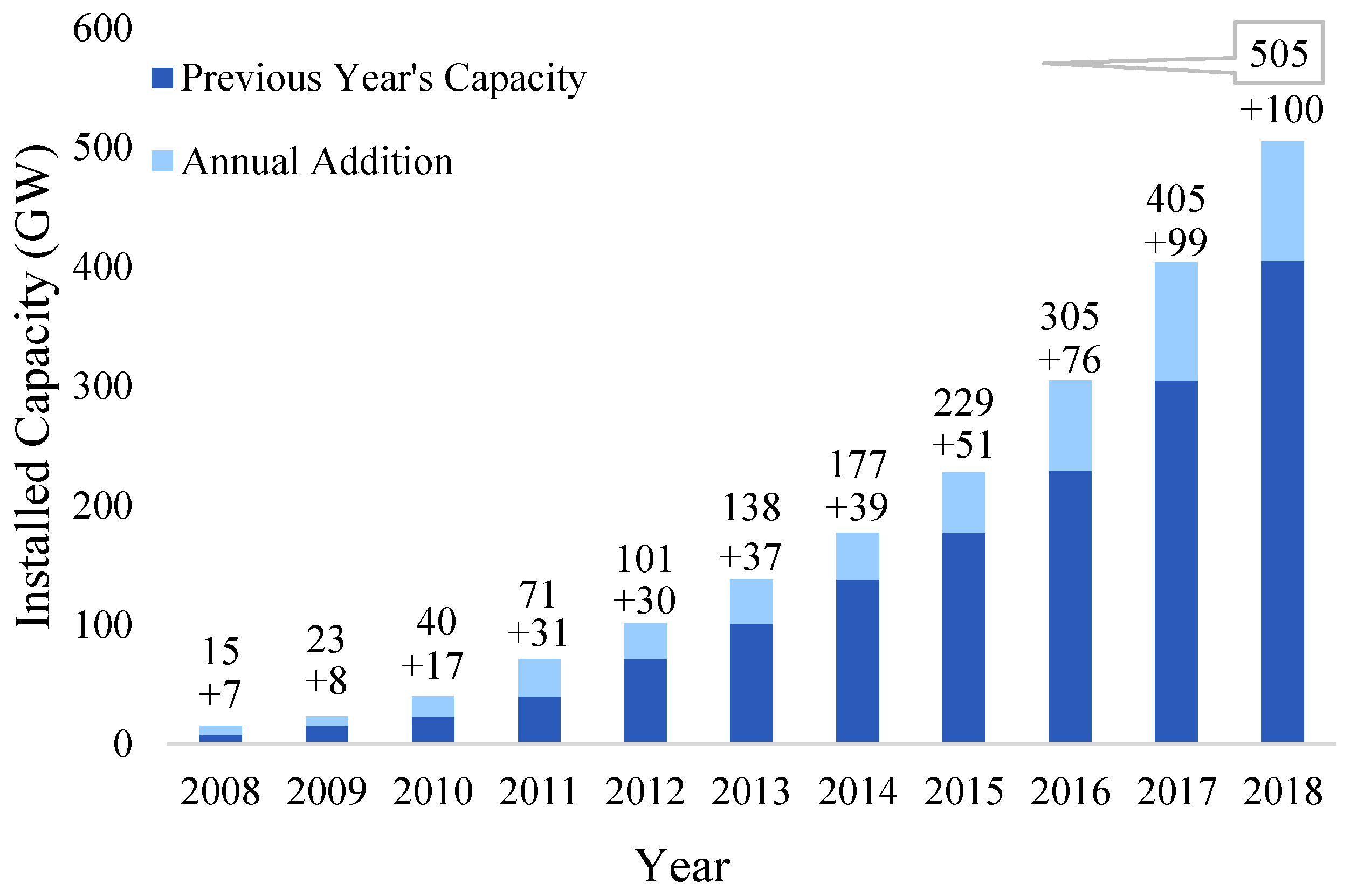
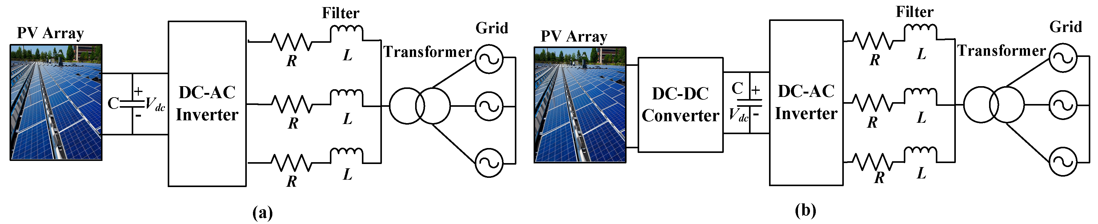
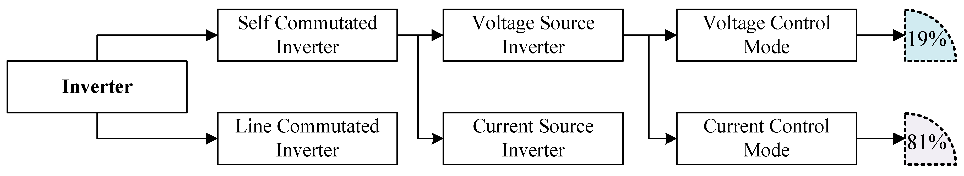
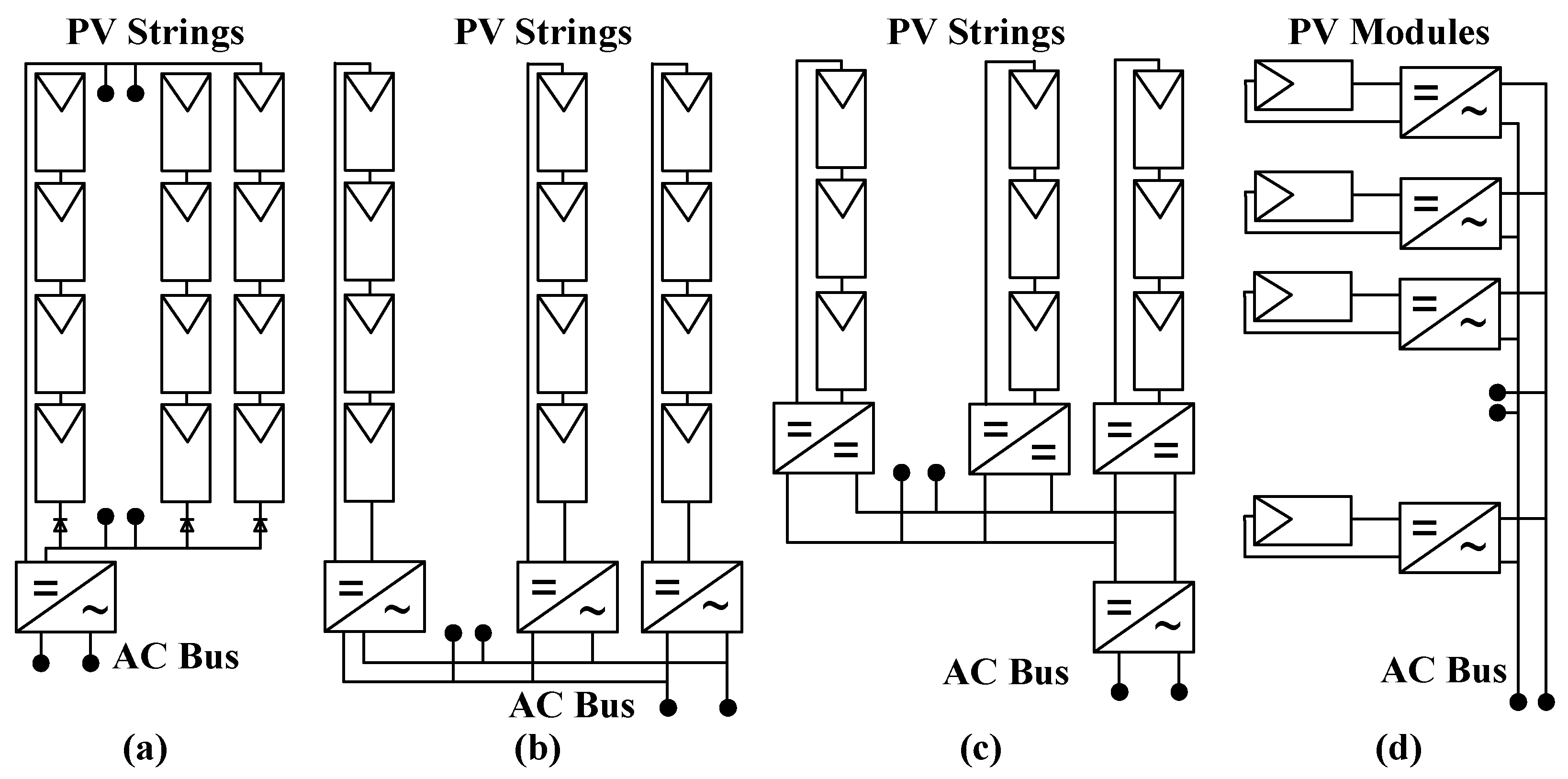
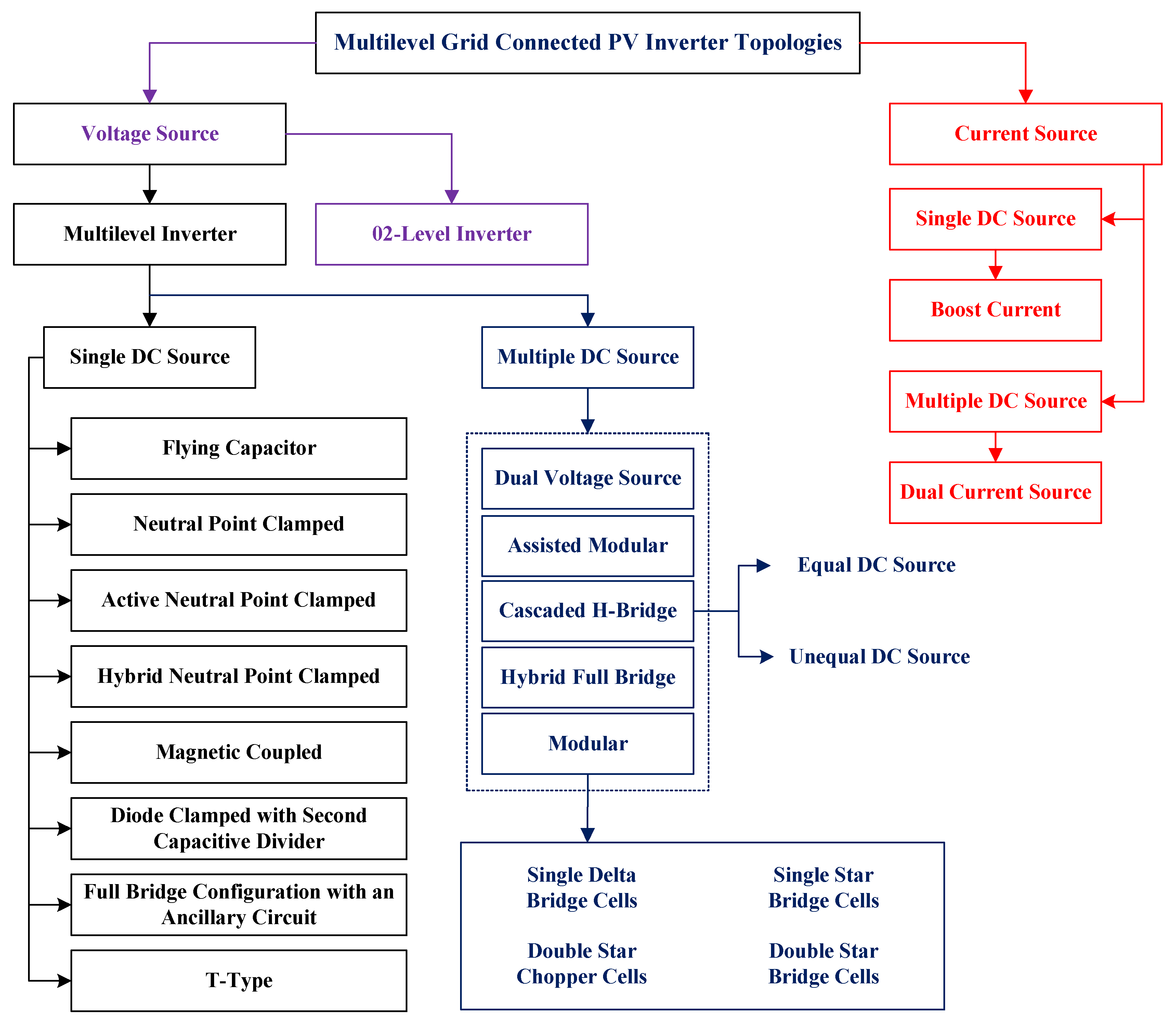
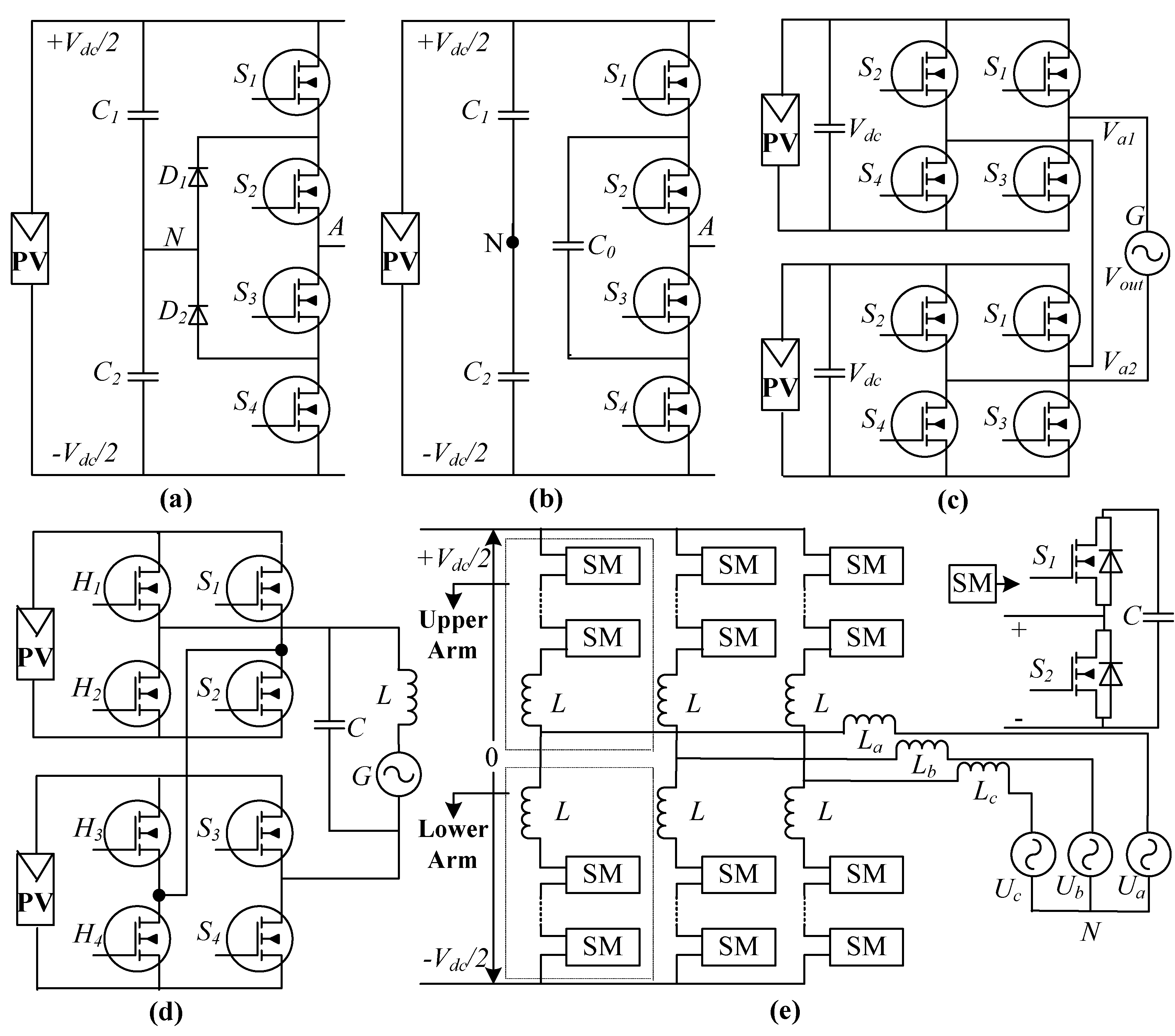
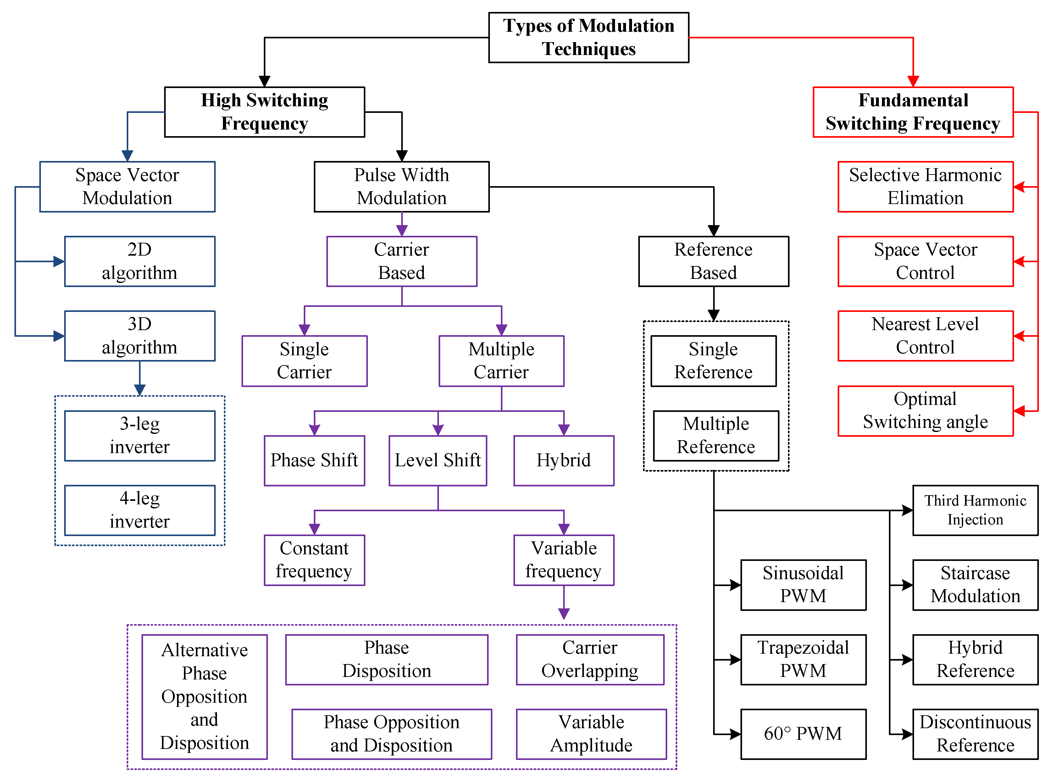
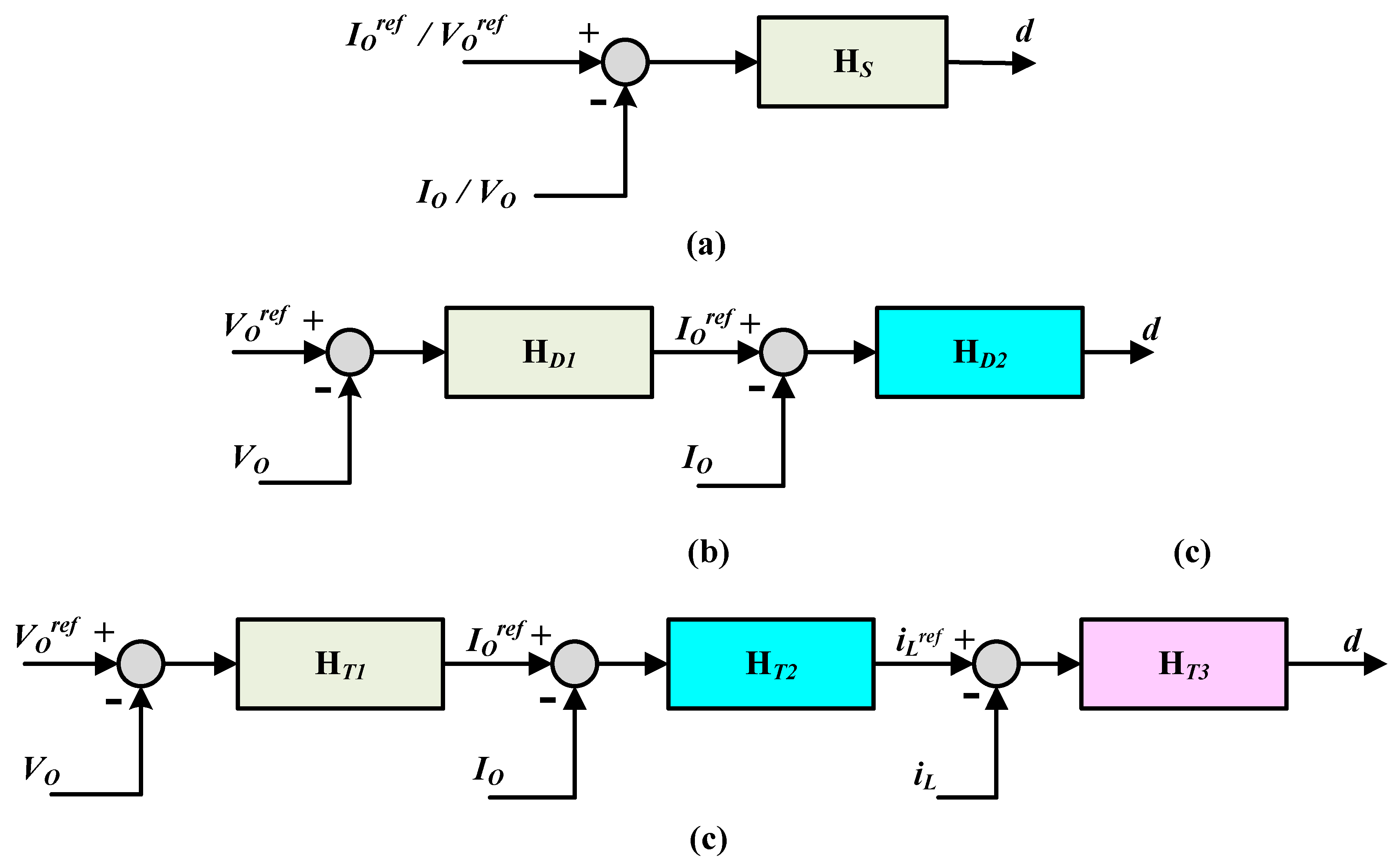
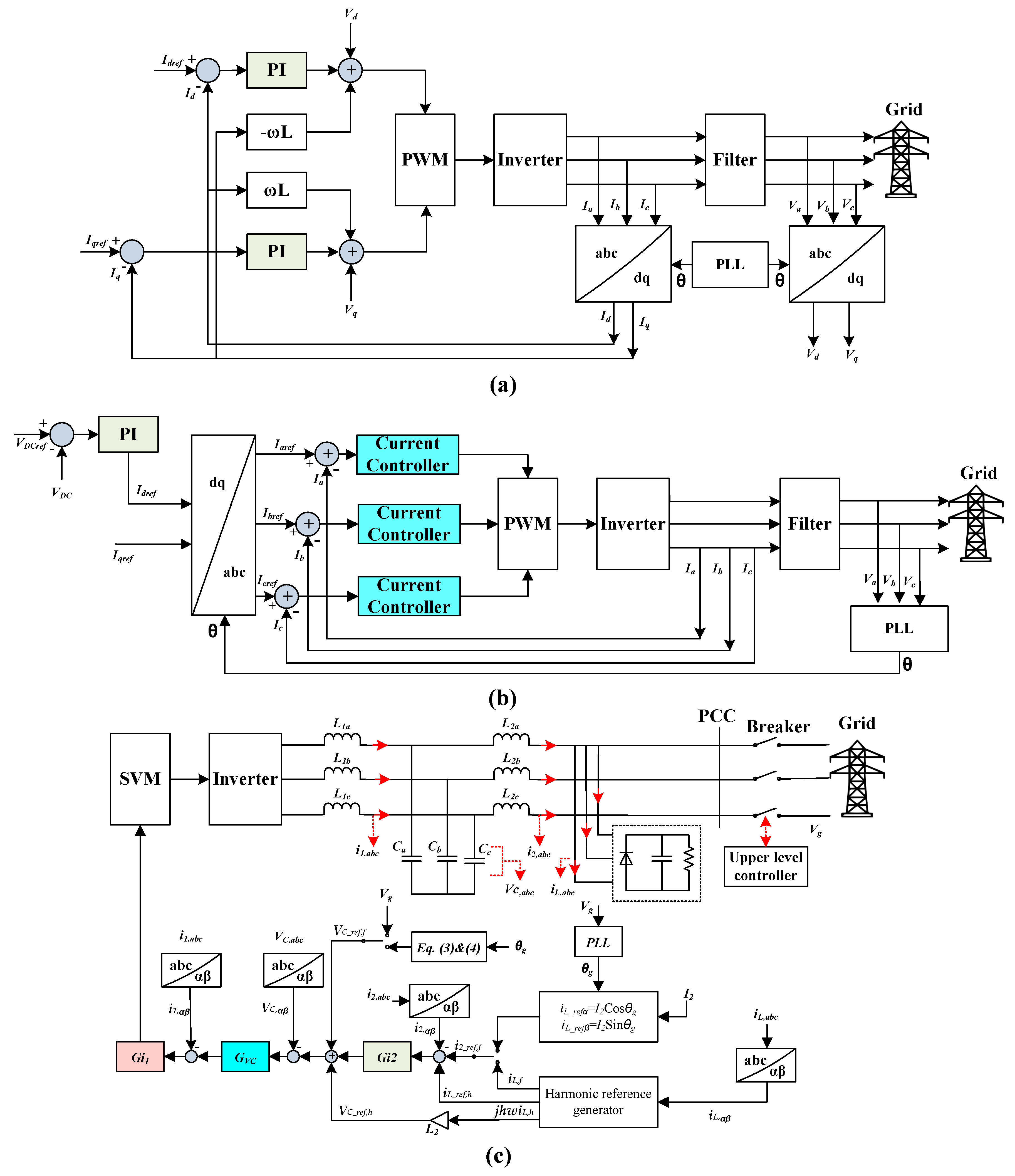
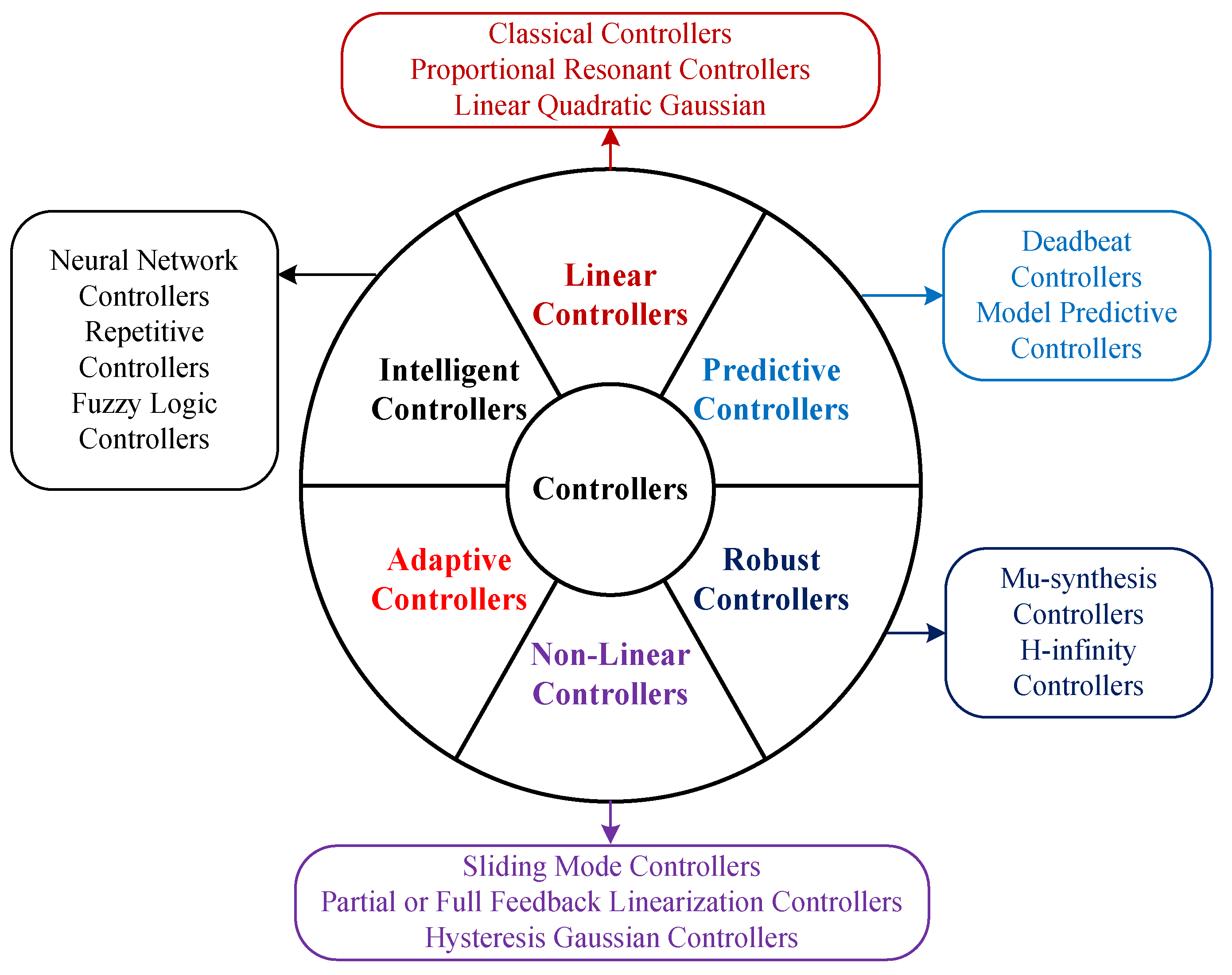
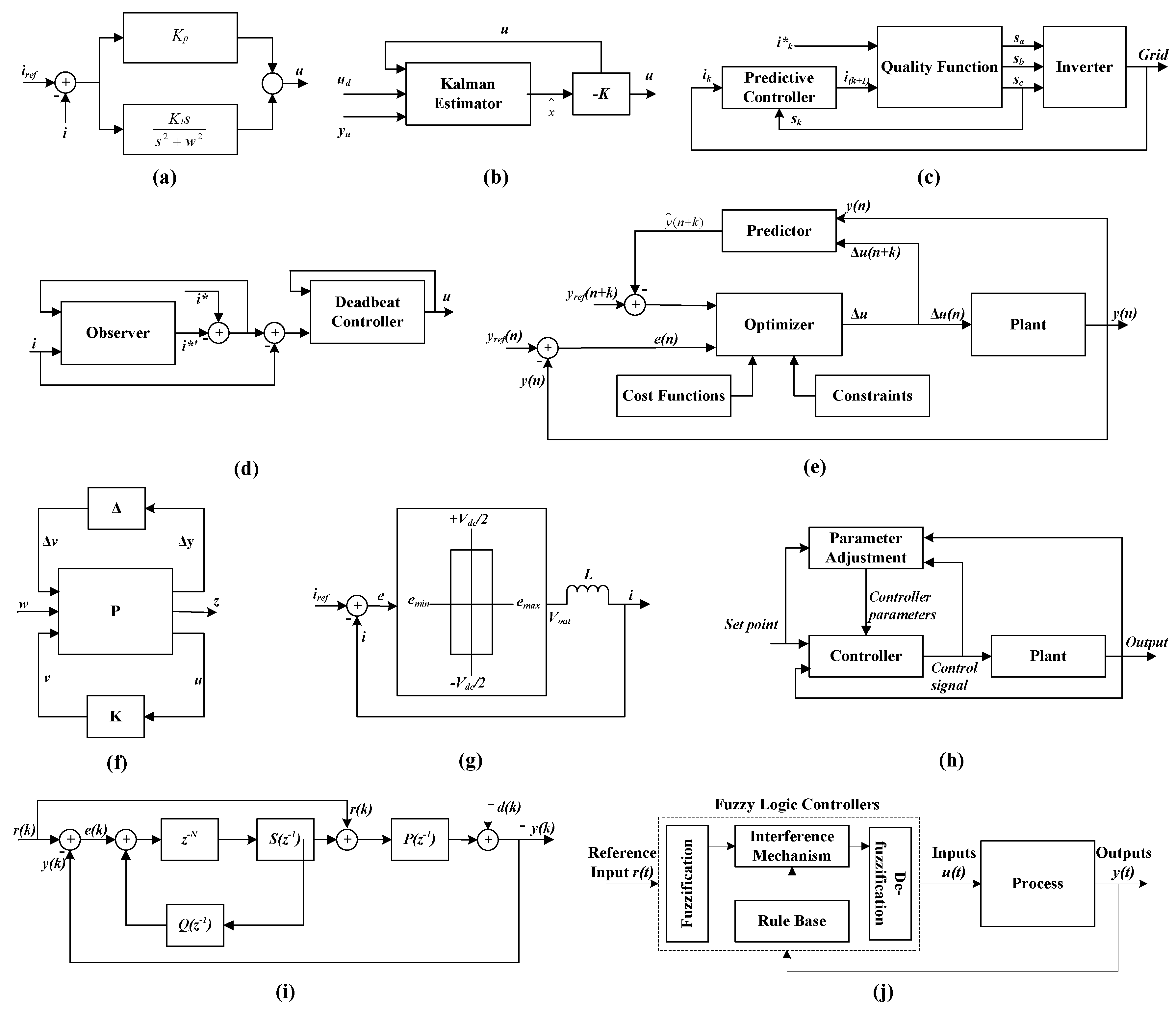
Table 1.
Comparative analysis of state-of-art literature review.
| Ref. | GS PV | PV CS | CI | IT | MT | CRF | CT | FS |
|---|---|---|---|---|---|---|---|---|
| [23] | ✓ | ✗ | ✓ | ✓ | ✗ | ✓ | ✗ | ✓ |
| [24] | ✓ | ✗ | ✗ | ✓ | ✗ | ✓ | ✗ | ✗ |
| [25] | ✗ | ✗ | ✗ | ✓ | ✓ | ✓ | ✓ | ✗ |
| [26] | ✓ | ✗ | ✓ | ✓ | ✗ | ✗ | ✗ | ✓ |
| [27] | ✓ | ✗ | ✗ | ✓ | ✗ | ✗ | ✗ | ✓ |
| [19] | ✗ | ✗ | ✗ | ✗ | ✓ | ✓ | ✓ | ✗ |
| [28] | ✗ | ✓ | ✓ | ✓ | ✗ | ✓ | ✗ | ✓ |
| [29] | ✗ | ✗ | ✗ | ✓ | ✓ | ✗ | ✗ | ✗ |
| [30] | ✗ | ✗ | ✗ | ✗ | ✗ | ✓ | ✓ | ✗ |
| [21] | ✗ | ✓ | ✓ | ✓ | ✓ | ✓ | ✓ | ✗ |
| [31] | ✓ | ✗ | ✓ | ✓ | ✗ | ✗ | ✓ | ✓ |
| [32] | ✗ | ✓ | ✓ | ✓ | ✗ | ✗ | ✗ | ✓ |
| [33] | ✗ | ✓ | ✓ | ✓ | ✓ | ✗ | ✗ | ✗ |
| [34] | ✓ | ✗ | ✓ | ✗ | ✗ | ✓ | ✓ | ✗ |
| [OS] | ✓ | ✓ | ✓ | ✓ | ✓ | ✓ | ✓ | ✓ |
Abbreviations: GS PV: Global Status of PV, PV CS: PV Configuration System, CI: Classification of Inverter, IT: Inverter Topologies, CRF: Control Reference Frames, CT: Control Topologies, FS: Future Scope, and OS: Our Survey.
| Performance | Central | String | Multi-String | AC Module |
|---|---|---|---|---|
| Very High | Variation of DC input voltage | ------ | ------ | Maintenance Installation cost MPPT efficiency Flexibility Reliability |
| High | Cables cost Voltage balancing DC power loss Switching loss Panels mismatching Robustness | Installation cost MPPT efficiency Flexibility Reliability | Variation of DC input voltage | AC Cables cost AC Power loss |
| Medium | Installation cost | DC Cables cost DC voltage variation AC Power loss Voltage balancing | Maintenance MPPT efficiency Flexibility Reliability Robustness DC and AC power loss Switching loss Installation and cables cost | ------ |
| Low | MPPT efficiency Flexibility Reliability Maintenance AC Power loss | Robustness Cables cost DC Power loss Switching loss Panels mismatching | Voltage balancing Panels mismatching | Voltage balancing |
| Very low | ------ | ------ | ------ | Robustness Cables cost DC voltage variation DC Power loss Switching loss Panels mismatching |
| Power rating | 1–50 MW | 1–5 kW/string | 1–50 kW | 500–600 W |
| Cost | Lowest cost | Costly than centralized inverter | Costly than centralized inverter | Highest cost |
The text in green shows the feasible characteristics, the text in red shows the disadvantage non-feasible characteristics, and text in blue shows the moderate characteristics.
Table 3.
Advantages and disadvantages of GCMLI.
| Type of GCMLI | Pros | Cons |
|---|---|---|
| NPC-GCMLI | Simple design Fast dynamic response Low voltage rating switches are needed High efficiency | As level increases the clamping diode count increases As level increases the complexity to balance the DC-link increases DC-link voltage regulation is required |
| FC-GCMLI | During power outage it has the capability to provide an extra ride through facility Phase redundant Low component count Low stress on components Low THD and have high modularity | As level increases the capacitor count increases As level increases the control system become more complicated High installation cost Less efficient due to low switching efficiency |
| CHB-GCMLI | Provide modular solution to achieve high voltage level Good fault tolerance Highly reliable | The inverter faces the problem of voltage misbalancing among the different phases Separate DC sources are used |
| M-GCMLI | Suitable for all voltage levels High modularity Low component count As the level increase the power switches count not increases Simpler structure Low THD and have compact size | High thermal losses High conduction losses High voltage ripples through SMs capacitors Current flows within inverter Large quantity of DC voltage sources (isolated) are required |
Abbreviations: THD: Total Harmonic Distortion; SM: Sub-modules; M-GCMLI: Modular Grid-Connected Multilevel Inverter.
Table 4.
Analysis of different grid-connected multilevel inverters.
| Ref. | MLI Topology | NOL | NOP | MT | C | SF (kHz) | CP (kW) |
|---|---|---|---|---|---|---|---|
| [67] | CHB | 05 | 3-Φ | SV-PWM | PI | 10 | --- |
| [68] | M | 7 | 3-Φ | MC-PWM | PI | 10 | 0.4 |
| [69] | Reduced switch | 7 | 1-Φ | MC-PWM | --- | --- | --- |
| [70] | E-Type | 7 | 3-Φ | PWM | --- | 20 | 4 |
| [71] | CHB | 13 | 1-Φ | PWM | --- | 5 | --- |
| [72] | Three phase | 5 | 3-Φ | MC-PWM | --- | 20 | 1 |
| [73] | Diode Clamped | 5 | 1-Φ | PWM | --- | --- | --- |
| [74] | symmetrical | 7 | 3-Φ | PWM | --- | --- | --- |
| [75] | Hybrid | 5 | 3-Φ | PWM | Finite Control Set-MPC | 6 | 7.5 |
| [76] | NPC Back to Back | --- | 3-Φ | PWM | MPC | 10 | 0.28 |
| [77] | CHB | 5 | 1-Φ | LS-PWM | FO-PID | 2 | --- |
| [78] | CHB | 7, 15 | 1-Φ | MC-PWM | --- | --- | --- |
| [79] | CHB with T type | m | 3-Φ | PS-PWM | PI | 3 | 1 |
| [80] | Modular | m | 3-Φ | LS-PWM | PR | 1 | --- |
| [81] | CHB | 7, 9 | 1-Φ | LS-PWM | CPT | 12 | 2 |
| [82] | Cascaded Full-bridge with FC | 9 | 1-Φ | PWM | Hysteresis | 20 | --- |
| [83] | Asymmetrical Cascaded | 17 | 1-Φ | SHE-PWM | --- | --- | --- |
| [84] | Quasi Z-Source Based NPC | 5 | 1-Φ | LS-PWM | PI | 10 | 0.5 |
| [85] | Modified DC link | 7 | 1-Φ | MC-PWM | --- | 6 | --- |
| [86] | NPC | 3 | 3-Φ | SV-PWM | --- | 2 | 1.1 |
Abbreviations: MLI Topology: Multilevel Topology; NOL: Number of Levels, NOP: Number of Phases, MT: Modulation Technique, C: Controller, SF: Switching Frequency, CP: Capacity, SV: Space Vector, LS: Level Shift, PS: Phase Shift, CPT: Continuous Power Theory, MC: Multi-carrier, and SHE: Selective Harmonic Elimination.
Table 5.
Comparative analysis of different switching angle calculation (SAC) methods [116].
Table 5.
Comparative analysis of different switching angle calculation (SAC) methods [116].
| α Calculation Methods | α, for i = 1, 2,…(n − 1)/2 | THD in Output Voltage | Nature of α | Remarks |
|---|---|---|---|---|
| Feed Forward | sin−1((i − 0.5)/n) | Small | High | Feasible for any voltage level |
| Half Equal Phase | 180°/(n + 1) | High | Low | Feasible for low voltage level |
| Equal Phase | 180°/n | High | Very Low | Feasible for low voltage level |
| Half Height | sin−1((2i − 1)/(n − 1)) | Medium | Moderate | Feasible for medium and low voltage levels |
Table 6.
Main characteristics of different controllers proposed in scientific articles.
| Ref. | NOP, CRF | CC | DLC | FL | CP | F | MT | A |
|---|---|---|---|---|---|---|---|---|
| [133] | 3-Φ, (dq) | MPC | --- | S-L | C | L | SVM | PV |
| [139] | 3-Φ, (abc) | DB, PI | DB | M-L | C, V | LCL | DPWM | G |
| [152] | 1-Φ | FSC-MPC | --- | S-L | C | L | PWM | G |
| [154] | 3-Φ, (dq) | μ-synthesis | PI | M-L | C, V | LC | PWM | PV |
| [158] | 3-Φ, (dq) | H-infinity | PI | M-L | C, V | LC | PWM | RE |
| [137] | 3-Φ, (dq) | SMC | --- | S-L | C | L | PWM | PV |
| [162] | 3-Φ, (αβ) | SMC-DPC | SMC-DPC | M-L | V, P | L | SVPWM | PV |
| [166] | 3-Φ, (dq) | FFL | LC | M-L | C, V | L | SVPWM | PV |
| [168] | 1-Φ | PFL | PFL | M-L | V, C | L | PWM | PV |
| [181] | 3-Φ, (abc) | Fuzzy Neural Network | Fuzzy Neural Network | M-L | V, P | L | PWM | PV |
| [182] | 3-Φ, (dq) | ANFISPID | ANFISPID | M-L | V, C | L | PWM | PV |
| [184] | 3-Φ, (dq) | Repetitive | --- | S-L | C | L | SVM | PV |
| [192] | 3-Φ, (dq) | PI | PI | M-L | V, C | LC | SVM | DG |
| [193] | 3-Φ, (dq) | Instantaneous Active Reactive Control | PI, PR | M-L | V, P | L | PWM | G |
| [194] | 3-Φ, (dq) | PI | PI | M-L | V, C | L | PWM | DG |
| [195] | 3-Φ, (αβ) | I | --- | S-L | C | L | PWM | DG |
| [196] | 3-Φ, (dq) | Reactive Power Control | PI | M-L | V, P | LC | PWM | PV |
| [197] | 1-Φ | PR | PI | M-L | V, C | LCL | PWM | G |
| [198] | 1-Φ | PI, PR | --- | S-L | C | LCL | SPWM | G |
| [199] | 1-Φ | PI, Hysteresis | PI | M-L | V, C | LC | PWM | G |
| [200] | 3-Φ, (αβ) | PR | PI | M-L | V, P | LCL | PWM | DG |
| [201] | 1-Φ | --- | Adaptive droop | M-L | V | LCL | PWM | G |
| [202] | 3-Φ, (dq) | Adaptive | PI | M-L | V, C | LC | SVPWM | DG |
| [203] | 3-Φ, (αβ) | MPC | --- | S-L | V, C | L | PWM | PV |
| [204] | 3-Φ, (αβ) | Hysteresis MPC | --- | S-L | C | LCL | PWM | G |
| [205] | 3-Φ, (αβ) | Predictive DPC | PI | M-L | V, P | L | PWM | PV |
| [206] | 3-Φ, (αβ) | MPC | --- | S-L | C | LCL | PWM | G |
| [207] | 3-Φ, (αβ) | Fuzzy | PI | M-L | V, C | L | SVPWM | PV |
| [208] | 1-Φ | Fractional order PR | --- | M-L | C, P | L | SPWM | PV |
| [209] | 3-Φ, (dq) | Fractional order PI | Fractional order PI | M-L | V, C | LCL | PWM | PV |
| [210] | 3-Φ, (dq) | PI | PI | M-L | V, C | LCL | PWM | PV |
| [211] | 3-Φ, (dq) | PR | PI | M-L | V, C | LCL | PWM | PV |
| [212] | 1-Φ | Fuzzy SMC | --- | S-L | V | L | PWM | PV |
| [213] | 3-Φ, (dq) | Droop | --- | M-L | V, C | LC | PWM | DG |
| [214] | 3-Φ, (dq) | PI | PI | M-L | V, C | L | PWM | PV |
| [215] | 3-Φ, (dq) | PI | PI | M-L | V, C | L | SPWM | PV |
| [216] | 3-Φ, (dq) | PI | PI | M-L | V, C | L | SVPWM | PV |
| [217] | 1-Φ | PI, MPC | PI, MPC | M-L | V, C | L | PWM | PV |
| [218] | 3-Φ, (dq) | PI, Vector control | PI | M-L | V, C | L | PWM | PV |
| [219] | 3-Φ, (dq) | Fractional order SMC | --- | S-L | C | L | PWM | PV |
| [220] | 3-Φ, (dq) | Voltage look-up table method | Voltage look-up table method | M-L | V, C | L | VLUT | DG |
| [221] | 3-Φ, (αβ) | H-infinity | --- | S-L | C | LCL | SVM | G |
| [222] | 3-Φ, (αβ) | MPC | --- | S-L | C | LCL | PWM | G |
| [223] | 1-Φ | Fractional order RC | --- | S-L | C | LCL | PWM | G |
Abbreviations: CRF: Control Reference Frames, NOP: Number of Phases, CC: Current Controller, DLC: DC-Link Controller, FL: Feedback Loop, CP: Control Parameters, F: Filter, A: Application, M-L: Multiple loop, S-L: Single loop, V: Voltage, C: Current, P: Power, DG: Distributed Generation, and G: General.
© 2020 by the authors. Licensee MDPI, Basel, Switzerland. This article is an open access article distributed under the terms and conditions of the Creative Commons Attribution (CC BY) license (http://creativecommons.org/licenses/by/4.0/).
Share and Cite
MDPI and ACS Style
Ali Khan, M.Y.; Liu, H.; Yang, Z.; Yuan, X. A Comprehensive Review on Grid Connected Photovoltaic Inverters, Their Modulation Techniques, and Control Strategies. Energies 2020, 13, 4185. https://doi.org/10.3390/en13164185
AMA Style
Ali Khan MY, Liu H, Yang Z, Yuan X. A Comprehensive Review on Grid Connected Photovoltaic Inverters, Their Modulation Techniques, and Control Strategies. Energies. 2020; 13(16):4185. https://doi.org/10.3390/en13164185
Chicago/Turabian StyleAli Khan, Muhammad Yasir, Haoming Liu, Zhihao Yang, and Xiaoling Yuan. 2020. "A Comprehensive Review on Grid Connected Photovoltaic Inverters, Their Modulation Techniques, and Control Strategies" Energies 13, no. 16: 4185. https://doi.org/10.3390/en13164185
Note that from the first issue of 2016, this journal uses article numbers instead of page numbers. See further details here.