Grid-Connected PV Generation System—Components and Challenges: A Review
by

Muhammad Hafeez Mohamed Hariri
1,*, 
Mohd Khairunaz Mat Desa
1,
Syafrudin Masri
2 and 
Muhammad Ammirrul Atiqi Mohd Zainuri
3 1
School of Electrical and Electronic Engineering, Engineering Campus, Universiti Sains Malaysia (USM), Nibong Tebal, Penang 14300, Malaysia
2
Faculty of Science and Technology, Universitas Muhammadiyah Bandung (UMB), Bandung 40614, Indonesia
3
Department of Electrical, Electronic and System Engineering, Faculty of Engineering and Built Environment, Universiti Kebangsaan Malaysia (UKM), Bangi 43600, Malaysia
*
Author to whom correspondence should be addressed.
Energies 2020, 13(17), 4279; https://doi.org/10.3390/en13174279
Submission received: 8 June 2020
/
Revised: 7 August 2020
/
Accepted: 11 August 2020
/
Published: 19 August 2020
(This article belongs to the Special Issue Power System Dynamics and Renewable Energy Integration)
Abstract
:Renewable energy (RE) has become a focal point of interest as an alternative source of energy to the traditional fossil fuel and other energy sources due to the fact that it is more environmentally friendly, abundant and economically feasible. Many countries aggressively promote feed-in tariff schemes and solar photovoltaic (PV) systems have become one of the fastest growing RE sources that can be integrated into the grid distribution network. This paper reviews the recent development of grid-connected PV (GPV) generation systems comprising of several sub-components such as PV modules, DC-DC converter, maximum power point tracking (MPPT) technique, and an inverter. In addition, various grid synchronization and islanding detection methods are elaborated. The future key challenges to build a smart and efficient GPV generation system were also presented.
1. Introduction
As both world population and standard of living increase, the demand for commercial energy is projected to continue its ascending trend [1]. The United Nations estimates the world population will further upsurge to 11.2 billion in the year 2100 [2]. Energy is the key determinant of the expansion of industrialization, a prerequisite for social development and its availability, as well as the pattern of consumption, plays an important role in sustainable development. According to the report of World Energy Outlook 2018 by International Energy Agency (IEA), world primary energy demand for the year 2017 led by oil accounting 31.74% and followed by coal 26.84%, natural gas 22.24%, renewables 9.55%, nuclear 4.92%, and solid biomass 4.71% as presented in Figure 1. The world RE consumptions has grown very rapidly in terms of electricity generation with the total share of 25% (6351 TWh—hydro 65%, wind 17%, PV 7%) in the year 2017 and is expected to achieve 41% (16,753 TWh—hydro 37%, wind 28%, PV 23%) in the year 2040 with implementation of New Policies Scenario [3]. Meanwhile, Energy Information Administration, (EIA) projects 48% increment in the world energy consumption from 2012 to 2040 (815 quadrillions Btu) [4]. Meeting rising energy demands pose a challenge to the utility planners and policymakers on managing this issue as it could result in insurmountable difficulties for energy security, air protection, and CO2 emission reductions.
It is recognized and acknowledged that renewable and non–conventional forms of energy will play a crucial role in the future as they are environmentally friendly, easy to use and are bound to become economically more feasible with increased usage [5]. RE term is derived from a broad range of resources all of which are based on self-renewing energy sources such as sunlight, flowing water, wind, the earth’s internal heat and biomass comprised of energy crops, agricultural, industrial and municipal waste. RE sources generate little if any greenhouse gases, waste, or pollutants that contribute to acid rain, urban smog, and health problems and do not require an environmental cleanup cost. In addition, these resources can be used to produce electricity for all economic sectors, fuels for transportation, heat for building and industrial processes [6].
Among all the various RE technologies, solar photovoltaic or precisely PV is the most exploited RE source alongside with hydro and wind power in terms of the pace of deployments and as it is considered a very promising source of future electrical power generation due to the abundance of sunlight over a large area of the earth surface thus giving rise to several applications of PV systems [7]. It also offers continuous cost reduction over the years, a stable system, fast technological progress, being maintenance and pollution-free [8]. There are two classes of the solar energy system, namely stand-alone and grid-connected PV (GPV) generation systems. Both systems have several similarities and differences in their implementations and purposes. By general definition, a stand-alone PV system produces power independently of the grid and a GPV system is an independent decentralized power system that is connected to an electricity transmission and distribution system [9]. The stand-alone PV system consists of PV modules or arrays together with converter and battery storage. Meanwhile, GPV system comprises two controllers as one is for MPPT and the other for inverter controls and grid synchronization. The stand-alone PV system is more favorable as compared to GPV system in areas where the extension of the national power grid is impracticable. The stand-alone PV system is used in off-grid applications together with battery storage. There are several applications in which stand-alone PV system is preferable as compared to GPV systems such as farm’s ventilation fans, water pumps, small circulation pumps for thermal water heating systems and even more advanced applications such as lighthouses, auxiliary power units for emergency services and others. The current set-up cost for a stand-alone PV system is high. The main disadvantage regarding the stand-alone PV system is the fluctuation of its output power due to the intermittence nature of solar irradiation and temperature. Therefore, battery storage elements are needed as a buffer system in order to compensate for this power instability and ensures steady power to the load. Moreover, this system suffers from low capacity factor, excess battery costs and finite capacity to store electricity consequently forcing them to dissipate the extra energy generated [10].
Meanwhile, recently the GPV system is playing an increasingly significant role as an electrical supply resource as well as an integral part of the electrical grid generation network. Single-phase, as well as a three-phase GPV system, poses some notable challenges to researchers. The challenges include the maximum power extraction from PV modules, rapid output variation, and daily variability of the output, the effect on power quality especially voltage and current harmonics, current backflow and a mismatch between PV output and grid demand. Contrary to single-phase system, the three-phase GPV generation system is commonly preferred in high–power applications as its ability to provide almost constant power flow and able to avoid excessive asymmetry in the grid current [11]. The maximum power transfer is the utmost objective regarding developing the GPV generation system. The optimization scheme based on the parameters customization on each of individual system components as well as recognizable challenges able to propel PV researchers to build a smart and efficient grid-connected PV generation system. In Figure 2 shows a single line diagram of a general structure for a GPV generation system.
There are several review papers reported in the literature which covers almost similar topic. Nevertheless, there are still some differences in the scope coverage. Details comparison between these papers is tabulated in Table 1.
Based on the outcomes from comparative analysis as in Table 1, this paper fills some of those gaps by providing a comprehensive overview on the development of each of the main components in GPV generation system. The review of the latest publications as well as current PV technological development allows the researchers especially in the field of PV to explore the new opportunity and initiate an innovative state-of-the-art ideals. The maximum power transfer, stability, safety, immunization against all types of disturbances, and power quality issues are still the main concerns regarding the reliability of GPV generation system. A collective summary of key challenges which covers almost a full range of spectrum on the topic sphere provides a preliminary conceptual framework to the development of future GPV generation system. In addition, this paper hopefully able to offers a valuable exposure not limited to young or future PV researcher nevertheless able to assist a wider group of researcher from different research background such as mechanical, civil and environmentalist to get a quick glance regarding the overall components of GPV generation system and furthermore able to help them to smoothly adapt to the current technological progress in GPV field.
The paper’s structure is a follows: Section 2 reveals the relationship between the irradiation and temperature with the generation of PV current; Section 3 presents the classification of DC-DC converters as Section 4 describes the fundamental concept of MPPT; Section 5 surveys a list of MPPT control techniques; Section 6 outlines the classification of an inverter; Section 7 overviews line filter and coupling transformers; Section 8 outlines grid-synchronization methods; Section 9 summaries the latest hierarchy of islanding detection methods; Section 10 provides standards and guidelines; Section 11 reviews the future key challenges posed by GPV system and lastly, Section 12 concludes the overall system.
2. Characteristics of Photovoltaic (PV)
PV exhibits numerous merits such as cleanness, low maintenance, no noise and regarded as one of the most essential RE sources. A PV cell is basically a semiconductor diode whose p-n junction is exposed to light. The irradiation level and temperature are the focal factors for the characteristic of the PV cell. Generally, the equivalent circuit of a PV cell is represented by a single diode model. The single-diode model composes of four components namely a photocurrent source , a diode parallel to the sources, a series resistor, and a shunt resistor, as displayed in Figure 3.
The series resistance, is the internal resistance of the cell and it depends on the resistance of the semiconductor. The shunt resistance, is due to leakage at the junction. The I–V characteristic of a PV cell is governed by the following equations:
where is the light current, as reverse saturation current of the diode, is Boltzmann constant, is ideality factor of the junction, is the output voltage of the PV cell and is the temperature in Kelvin and is the PV cell output current. PV cells are then combined in series and parallel connection to form larger units called PV modules, which are further interconnected in a series-parallel configuration created PV arrays.
Nowadays, there are various types of PV modules available in the market, which can be classified into several main categories [15]. Mono and polycrystalline silicon PV modules type are well-known matured technologies that dominate the commercial PV market. They are known as the first generation of PV technology which reached a conversion efficiency of more than 20% recently [16]. The second generation of PV is thin-film technologies. Thin-film PV modules have a lower efficiency as compared to the first generation yet still offer cheaper cost to manufacture. Moreover, this kind of module deals with much more flexible design as it includes amorphous silicon (a-Si) and microcrystalline silicon materials. The main goal for each of the PV module manufacturers is to continue to develop a lower cost, highly reliable and simultaneously, attain great conversion efficiency. Figure 4 illustrates the highest PV module conversion efficiency according to the type of materials and technology used. The efficiency of the PV module is a closer indication to the commercial PV efficiency value in comparison to cell efficiency value. This is due to the fact that the wider area was used, and the technology is more ready for commercialization. For silicon types of PV technology, the highest module conversion efficiency is achieved by SunPower and Panasonic through Interdigitated Back Contact (IBC) and Heterojunction IBC structure at 22.8% and 24.4% respectively. The IBC structure allow more light capture by eliminating front busbar that common in silicon PV module structure [17]. For type III–V material category, highest efficiency was attained at 25.1% and 31.2% for single and three junctions respectively at non-concentrating irradiation. Emerging PV technology like Perovskite is currently at 16.1%. While highest PV efficiency was recorded more than 40% from hybrid four junction PV technology (UNSW), it is very complex structure and measured at concentrated level of irradiation. The usage of high efficiency PV module has the advantage of reducing the active installation area, material use and balance of system although initial cost might be expensive.
3. Topology of DC-DC Converter for GPV System
The amount of PV array output voltage depends on the individual arrangement of PV modules. Due to the intermittence characteristic of PV source, load specification and the need to provide a constant DC voltage with high efficiency, a regulator or a DC-DC converter is required in most PV applications in order to regulate or control the DC output voltage that PV arrays generate [18]. Figure 5 shows the classification of isolated and non-isolated DC-DC converters. As the installation trend of PV system moves towards large scale plant and grid-connected scheme, it is crucial to further enhance the capabilities of the DC-DC converter so as to achieve a higher power rating and a higher voltage level at the point of common coupling (PCC).
Theoretically, a conventional DC-DC boost converter is able to deliver high voltage gain. However, when it comes to hardware implementation, the voltage gain of the DC-DC boost converter is insufficient due to the losses associated with the switching devices and the passive elements integrated into the circuitry. To overcome these issues, three different types of high voltage gain interleaved DC-DC converters have been developed [19]. The results show the proposed converter topologies works well with PV and Fuel Cell (FC) systems. Moreover, a comparative analysis of various converter topologies relates to high voltage gain DC-DC converters have been reported by the authors [20]. Most of the topologies mentioned are based on the structure of conventional boost converter are specifically categorized under their ability to provide fixed or multiple times voltage gain.
4. Maximum Power Point Tracking (MPPT)
Currently, the average efficiency rating of PV modules available on the market today is close around 20 % [21]. In order to extract maximum power that PV modules could harvest; researchers have come out with numbers of the MPPT technique. MPPT is a power control technique that operates the PV modules in such a way allows the modules to deliver all the available power it has. Examine a graph of PV array battery charging power transfer as illustrated in Figure 6. This chart is able to give a better understanding of how MPPT works.
Suppose that when a conventional PV module connects directly to the battery, it will force the module to operate at battery’s voltage level of 12 V which is not an ideal operating voltage level for the available maximum power that a PV module is capable of generating. Therefore, there is a portion of power that could not be extracted from the module and it is wasted power. The implementation of MPPT will vary the electrical operating point of the PV module so that the module is capable to deliver the maximum available power at the optimal value (maximum power point, MPP) of its voltage and current rated level.
5. MPPT Control Strategy
Recently, there are numerous MPPT control strategies presented in the literature. These control methods vary in complexity, cost, sensor required, convergence speed, implementation of hardware circuits, and other aspects. However, according to the development history of techniques, they can be classified into two categories, namely conventional techniques and artificial intelligent (AI) techniques [22]. The most significant conventional techniques are hill climbing (HC), perturbation and observation (P&O), incremental conductance (INC), fractional open-circuit voltage (FOCV) and fractional short-circuit current (FSCC). Meanwhile, the most applicable AI techniques are Fuzzy Logic (FL), artificial neural network (ANN) and soft computing methodologies. The main obstacle raised by MPPT techniques is to automatically find the real voltage at which a PV module should operate to attain the maximum power output under a given PV surface temperature and irradiation [23]. Several techniques as mentioned previously are discussed in detail in an arbitrary order.
5.1. Hill Climbing (HC)
HC is a popular MPPT technique ever developed due to its simplicity and easy implementation [24]. The flow diagram of a classical HC technique as well as Power-Duty (P-D) curve as illustrated in Figure 7 and Figure 8 respectively, operated with a fixed duty cycle size which controls the sign of the P-D curve’s slope on each calculation step and makes the appropriate voltage alteration.
The duty cycle, , in every sampling period is determined by the comparison of the power at the present time and previous time. If the incremental power , then the duty cycle should be increased in turn to make . Then if , the duty cycle is reduced to make . Shortcomings of the HC method are described below. Figure 8 is the P-D curve diagram of PV modules when the power interface device is a DC-DC buck converter. If the initial operating point of the PV system is located on the left side of the MPP, the duty cycle has to be continuously increased on the basis of the judgment procedure of the HC method in order to track the maximum power point. When the operating point of the PV module is located on the right side of the MPP, the duty cycle should be continuously reduced to return back to the maximum power point. However, if the operating point wants to move toward the MPP (), the incremental duty cycle should be greater than zero () according to the judicial procedure of the HC method. This will cause the operating point to move farther away from the MPP. Therefore, a misjudgment of tracking direction during changing weather condition may happen under this kind of situation. For the HC method, this misjudgment is a fatal weak point [25].
5.2. Perturbation and Observation (P&O)
The P&O algorithm control technique like HC is widely used in the MPPT controllers due to its simple structure and fewer required parameters [26]. This method finds the MPP of PV modules by means of iteratively perturbing, observing and comparing the power generated by the PV modules. The P&O technique comprises a perturbation in the operating voltage of the PV module, while HC strategies involve a perturbation in the duty ratio of the power converter [27]. The flow chart of the typical P&O algorithm is shown in Figure 9.
The algorithm is started by reading the value of current, and voltage, from the PV module. The power, is then calculated from the measured voltage and current. The value of voltage and power at the instance is stored. Then next values at instance is measured again and power is calculated from the measured values. The power and voltage at instant are subtracted with the values from the instant. In the P-V curve of the PV module, it is inferred that in the right-hand side curve where the voltage is almost constant and the slope of power voltage is negative whereas in the left-hand side, the slope is positive . Therefore, the right side of the curve is for the low duty cycle (near to zero) whereas the left side curve is for the higher duty cycle (nearer to unity). Depending on the sign of and after subtraction, the algorithm decides whether to increase or to decrease the duty cycle of the converter. P&O and HC techniques can malfunction under rapidly changing atmospheric conditions [28]. As illustrated in Figure 10, the starting point is point A, and a voltage perturbation will move the operating point from A to B and cause a decreasing power when the weather condition is steady. According to the judging rules of the P&O method, the next perturbation should be changed to in the opposite direction. However, if the irradiation increases and shifts the power curve from P1 to P2 within one sampling period, the operating point will move from A to C instead of A to B. This represents an increase in power and the perturbation is kept the same. Consequently, the operating point diverges from the MPP and will keep diverging if the irradiation steadily increases and vice versa. The power loss of PV modules will increase and therefore, the efficiency of the PV system eventually will fall.
Another drawback of the P&O method is that, as the MPP is reached, the power tracked by the P&O method will oscillate and perturb up and down near the MPP as the module terminal voltage is perturbed for every MPPT cycle resulting in a loss of PV power especially in cases of constant or slowly varying atmospheric conditions. The magnitude of the oscillations is determined by the degree of variations of the output voltage or duty cycle [29].
5.3. Modify P&O
The modified P&O is presented [30]. The experimental result work shows that the adopted proposed modified MPPT control algorithm improved the accuracy as well as a fast response as compared to conventional P&O method [31]. The authors [32] came out with the estimate perturb-perturb (EPP) method that uses one estimate mode between two perturb mode. Furthermore, in order to minimize the negative effects associated with the classical P&O method especially during rapidly changing atmospheric conditions, the P&O MPPT parameters should be customized to the dynamic behavior of the specific converter adopted as reported [33]. Precisely, the MPPT parameters which contains the fixed duty cycle step size, and sampling time, are customized to the dynamic behavior of the specific converter and PV module adopted.
On the other hand, the oscillation around MPP can be minimized by reducing the perturbation step size. However, a smaller perturbation size slows down the MPPT and the system shows poor dynamic response. A larger perturbation step size could cause large fluctuations of output power resulting in energy dissipation. A solution to this conflicting circumstances is to have a variable perturbation step size that gets smaller towards the MPP as discussed [34]. By varying the step size value as well as the sampling time reduces the oscillation around the MPP and steers to a faster response. Meanwhile, [35], a linearization around the MPP leads to a good selection of the sampling period, and the duty cycle variation, in order to reduce the number and the amplitude of oscillation around MPP in the typical P&O algorithm. It can be concluded that, the stability of the PV system and rapidity of the MPPT algorithm is to compromise by having a good selection of the adaptive sampling period as well as perturbation step size towards the MPP.
5.4. Incremental Conductance (INC)
The INC MPPT technique is based on the fact that the slope of the P-V curve as in Figure 8 is zero at the MPP, positive on the left of the MPP and negative on the right. The flow diagram of the INC method and INC conditions is illustrated in Figure 11 and mentioned in Equations (2)–(4) respectively.
The advantage of the INC MPPT method, which is superior to those of the other two HC and P&O algorithms, is that it can calculate and find the exact perturbation direction for the operating voltage of PV modules. In theory, when the MPP is found by the judgment conditions of the INC method, it can avoid the perturbation phenomenon near the maximum power point which usually happens to the previous MPPT algorithms. The value of operating voltages is then fixed. However, it indicates that the perturbation phenomenon is still happening near the MPP under non-uniform weather conditions during experimental tests [36]. This is due to the reason that the probability of meeting condition is extremely small plus the deterministic process of INC algorithm is more complicated, therefore the simulation time spent by INC MPPT algorithm is a little bit longer than that of HC and P&O.
5.5. Fractional Open-Circuit Voltage (FOCV)
This method is based on the observation that, the ratio between module voltage at maximum power, to its open-circuit voltage, is nearly constant [37].
Although the execution of this method is simple and easy, its tracking efficiency is relatively low due to the utilization of inaccurate values of the constant in the computation of . Once the constant is known, is computed by measuring periodically. This factor has been reported to lie between 0.71 and 0.78.
5.6. Fractional Short-Circuit Current (FSCC)
This method results from the fact that the current at the maximum power point is approximately linearly related to the short-circuit current of the PV array [38].
The MPP tracking is completed by measuring the short-circuit current . However, is not constant. It lies between 0.78 and 0.92. The accuracy of the method and tracking efficiency depends on the accuracy of are the periodic measurement of short-circuit current.
5.7. Fuzzy Logic (FL), Artificial Neural Network (ANN) and Other Algorithms
The PV module’s MPP varies with the irradiation and surface temperature since the module exhibits a non-linear current-voltage or power-voltage characteristic. Some artificial intelligent prediction tools, such as FL or ANN, control with non-linear and adaptive in nature is introduced in the PV MPPT control mechanism. By knowledge-based Fuzzy rules, Fuzzy control can track the MPP of the PV module [39]. On the other hand, an ANN control executes like a black-box model, requiring no detailed information about the PV system. After learning the relation between maximum power point voltage and open-circuit voltage or irradiation and temperature, the ANN control can track the MPP during a real-time scenario. Since most PV arrays have different characteristics, ANN has to be specifically trained for the PV module with which it will be used. The characteristics of the PV module also change with time, implying that the ANN has to be periodically trained to guarantee accurate MPPT [40]. Ref. [41] presents a high-performance tracking of maximum power delivered from PV systems using adaptive neural Fuzzy inference systems (ANFIS). This method combines the learning abilities of ANN and the ability of FL to handle imprecise data. Moreover, due to the emerging technology especially on the computing-based, enormous MPPT techniques are developed in order to overcome some limitation occurred in previous approaches. Most of the newly emerged MPPT techniques are able to relocate the true MPP effectively even under partial shading condition. However, the main disadvantage of these controls is the high cost of accomplishment owing to complex algorithms that usually need a digital signal processor (DSP) as their interface platform.
Comparison of major MPPT techniques found in the literature is tabulated in Table 2. RCC stands for ripple correlation control, FL, ANN, particle swarm optimization (PSO), genetic algorithm (GA), radial movement optimization (RMO), biological swarm chasing algorithm (BSCA), ant colony optimization (ACO), cuckoo search (CS), salp swarm algorithm (SSA) and grey wolf optimization (GWO). Among these MPPT techniques, the modified variable-step INC is found to be the best promising technique among other conventional approaches in the literature. On the other hand, PSO proved to be an effective method among new generations of MPPT techniques which are based on soft computing. PSO is able to provide accurate, fast convergence speed and able to work effectively even under partial shading conditions. Furthermore, detailed analysis carried out by the authors [42] demonstrated the superiority of GWO among other distinctive meta-heuristic optimization algorithms in terms of speed and reaction time to reach MPP.
6. Inverter
Inverter is an electronic device or circuitry that changes a DC input voltage to asymmetric AC output voltage of desired magnitude and frequency [65]. Inverters can be broadly classified into two main classes which are line-commutated and self-commutated inverters as shown in Figure 12. It furthermore can be structured into many sub-categories which are based on the types of input source, output characteristics, method of connections, types of load, pulse-width modulation (PWM) switching techniques and also based on the number of output voltage level.
The line-commutated inverter (LCI) depends on the grid parameters that dictate the commutation process. In addition, it requires some additional circuitry to turn-off the switching devices. On the other hand, the self-commutated inverter (SCI) is a fully controlled device. The potential at the gate terminal controls the whole operation of the switching device. Since the SCI is controllable, it is able to control both the current as well as voltage waveform at the output side of the inverter. Furthermore, it is well recommended for GPV system as it is highly robust to grid disturbances, able to suppress current harmonics and therefore able to improve the grid power quality. SCI can be further divided into three sub-categories which are Voltage-Source Inverter (VSI), Current-Source Inverter (CSI) and Impedance-Source Inverter (ISI). The two most common type of SCI for grid-connected operation is VSI and CSI. VSI is fed from a DC voltage input having small or negligible impedance and the output voltage does not depend on the load. Meanwhile, CSI is fed with adjustable current from a DC voltage input source having high impedance. The amplitude of the output current is independent of the load impedance [70]. VSI is a more preferable converter scheme over CSI for several reasons such as it offers better loss reduction, easy to control, reduction in filtering requirement, and provide improved quality of the produced voltages and currents especially for the grid-connected system.
7. Line Filter and Coupling Transformer
Power electronic circuit such as DC-DC converters or an inverter produces high order harmonic that flow into the grid will create harmonic pollution thus affecting the power quality of the grid [71]. Passive and active harmonic power filters (APF) are used to reduce voltage distortion, current harmonics and able to act as a reactive power compensation in distributed generation systems [72]. A passive filter contains passive elements such as a resistor, capacitor, and inductor connected in several arrangements which responses to a frequency range of 100 Hz to 300 MHz. On the other hand, APFs have different configurations which are shunt, series, and hybrid as illustrated in Figure 13. APFs are capable of dealing with low-frequency range as well as able to provide flexible gain.
The introduction of the coupling transformer in a GPV system is based on two main reasons. A large 50 Hz coupling transformer is often paired at the inverter output as it works as galvanic isolation and to prevent DC current injection into the distribution grid. Excessive DC current injection into the grid network creates corrosion in underground equipment and leads to transformer saturation [73]. Moreover, a coupling transformer’s role as an interface to the magnitude of the PV array voltage could minimize the effect of leakage current. The implementation of a transformer, however, will lead to additional circuitry losses and consequently bring down the overall system efficiency. Meanwhile, the use of solid-state transformer offers size and weight reduction as it works on a high frequency [74]. The grid-connected PV system without coupling transformer raises another complication which is the creation of leakage current components. The occurrence of ground leakage current as presented in Figure 14 exist in transformer-less GPV system as the parasitic elements within the system is not properly grounded.
8. Grid Synchronization
As discussed earlier, the GPV generation system received extensive attention as more researchers focus on the integrated and smart-grid distribution power system. The implementation of these systems requires deep understanding, critical evaluation and detail analysis in case of normal and abnormal operation. In order to synchronous single-phase or three-phase inverter system to the grid distribution network, four vital conditions must be met as tabulated in Table 3.
The synchronization must occur in the first place before connecting the PV system to the grid. The main purpose of grid synchronization is to allow and automatically take the control action to prevent the abnormalities of parameters between the PV system, and the grid. Moreover, the variables such as phase sequence, voltage magnitude, frequency, and phase angle should be continuously monitored within the permissible limits in order to guarantee a safe and effective synchronization operation of PV power converters connected to the grid.
A GPV system can be modeled as having two sources on each side with intermediate reactance in between as shown in Figure 15a.
Figure 15b represents the phasor diagram of the fundamental components including the inverter output voltage , the inverter output current , the voltage drop on the line reactance and the fundamental component of the grid voltage . The symbol represents the power angle between the grid and inverter output current meanwhile represents as the phase difference or load angle between the grid and the inverter output voltage. These relationships are governed by Equations (7) and (8) respectively,
The direction of power flow from an inverter to the grid or vice versa can be controlled by fine-tuning the inverter output voltage magnitude and phase difference with respect to the grid while the inverter phase sequence as well as its frequency are monitored closely. The summary of the operation is presented in Table 4. It is clear that maximum power delivery can be made when the phase difference between inverter and grid voltage is . However, if , these two voltages are unable to synchronous and are unstable. Therefore, the angle difference should be slightly lower than in order to achieve maximum power transfer from the PV source to the grid.
8.1. Control Mechanism for GPV System
The power transferred or injected from the PV system into the grid must be continuously monitored, controlled and analyzed. Designing a GPV system employs two control loops which are external voltage and internal current control loop respectively. The voltage control loop is used to regulate the output power from PV modules to the grid as well as to balance the power flow, whereas the current control loop is used to regulate the injected current to the grid and keep it in phase with grid voltage to achieve unity power factor [81]. Many control mechanisms have been proposed in the literature to regulate the inverter output current that is injected into the grid. Among these control mechanisms are hysteresis controller, predictive and linear proportional-integral (PI) controller, Fuzzy proportional-integral (FPI) and others [82]. Among all, the PI controller is the most common control algorithm used for current error compensation [83]. A PI controller calculates an error value as the difference between a measured inverter output current and a desired injected current to the grid, then the controller attempts to minimize the error between them.
Current control in a synchronous (rotating) reference frame (SRF) using PI controllers is the typical solution, especially in the three-phase grid-connected inverters [84]. As shown in Figure 16, Clark’s transformation transforms three-phase grid quantities vector from ABC natural reference frame into balanced two-phase quantities (α–β) and then converting to two-phase rotating reference frame by using Park’s transformation which defined as the direct (d) and quadrature (q) components respectively.
Transforming natural frame AC variable quantities into a DC quantity two-phase rotating reference frame makes filtering and controlling easily achievable [85].
The transformation from three-phase stationary reference frame into two-phase rotating reference frame has also been called as D-Q transformation and it is governed by Equations (9)–(11) respectively.
According to the mathematical model of the three-phase GPV system as discussed [86], the output voltages of the inverter in the SRF are given by Equations (12) and (13) respectively.
where , , and are DC components of the grid voltage and current respectively whereas , , and are DC components of the inverter output. These DC quantities are then transformed back into the ABC natural frame where they will be used as a reference signal for sinusoidal pulse-width modulation (SPWM) to generate proportional duty-cycle switching sequence to the three-phase inverter. By referring to Equation (11), the transformation of the reference frame from AC quantities into DC quantities require a value of which is the information of phase angle of grid. There are numerous methods used to obtain the grid information especially phase angle value. Among the methods available in the literature, phase-locked loop (PLL) is the most acknowledged owing to its simplicity, effectiveness and robustness in various grid conditions [87].
8.2. Phase-Locked Loop (PLL)
The role of the PLL is to provide the rotation frequency (ω), direct (d) and quadrature (q) voltage or current components by resolving the grid ABC natural components. It synthesizes the frequency and phase of grid voltage and current correspondingly. Moreover, it is able to provide the frequency and phase angle of the grid voltage correctly even though in the event of disturbance [88]. The principle operation of three-phase PLL is based on the closed-loop control system as displayed in Figure 17 which regulates to zero and locks to the phase angle of the input signal .
The gains of the PI controller are designed in such a way that follow the reference value . This results in an estimated phase angle that equals the phase angle original, therefore, a phase difference of zero [89]. The general structure with the entire components of the three-phase GPV system is presented in Figure 18. There are two controller blocks employed in this system. The first controller block implements MPPT on the input side of the converter. Normally the voltage and current of PV modules are set as the input and duty cycle is the output parameter. The next controller generates PWM to the three-phase inverter. The extraction of the phase angle from the grid voltage is vital. There are three technical aspects that are very crucial for the effective grid synchronization scheme. The primary one is to regulate the DC link voltage to make it constant. The next one is a controller which control active power injected into the grid. The third one is to control reactive power compensation. [90], a full working three-phase PLL for GPV system with coupling transformer has been designed. Furthermore, there are studies that compare the performance of a GPV generation system with and without coupling transformer. Both system’s configurations have its own advantages and disadvantages as detail analysis regarding this implementation are provided by the authors [91].
The designing of a synchronization control algorithm must be able to cope with the disturbances of grid parameters such as voltage, frequency, and phase angle. It is expected that the faster and the more accurate these measurements are the better the synchronization and therefore the more efficient the control actions. It is well-known that PLL is the most popular synchronization technique available in the literature. However, recently there is a vast spectrum of grid synchronization techniques available which can be divided into two categories which are for open-loop and closed-loop system. Open-loop systems directly detect the magnitude, phase, and frequency of the input signal whereas closed-loop systems adaptively update the detected parameters through a loop mechanism. Artificial intelligence (AI), zero-crossing detection (ZCD), adaptive notch filtering (ANF), delayed signal cancelation (DSC), nonlinear least square (NLS), discrete Fourier transform (DFT), Kalman filter (KF), and frequency-locked loop (FLL) are among numerous grid synchronization control techniques available in the literature. Figure 19 shows the classification of synchronization up-to-date techniques. [92] elaborate in detail some of the mentioned synchronization control techniques together with their applications. The authors emphasize that more attention is required to focus on hybrid techniques for robust grid synchronization especially in adverse grid conditions.
Since PLL is the most common grid synchronization technique, there is plenty of derivation generated from this method. A comprehensive review of major PLL techniques has been carried out in [93] which includes synchronous reference frame (SRF), instantaneous real and imaginary power theory (PQ), double synchronous frame (DSF), sinusoidal signal integrator (SSI), double second-order generalized integrator (DSOGI), enhance PLL (EPLL), three-phase magnitude (3MPLL), quadrature method (QPLL), robust PLL (RPLL), adaptive linear combiner (ALC), multi-rate (MR), and as well as adaptive PLL (APLL). Each of these techniques depends strongly on the system specifications and requirements. Some of the proposed schemes did not provide the corresponding results or hardware verifications. Yet, the main goals are it should be able to provide fast and accurate synchronization information along with the high degree of immunity and insensitivity towards disturbances in the input signal thus making the grid synchronization as well as power transfer mechanism working effectively within the given standards and regulations.
9. Islanding Detection Methods
Apart from the grid synchronization mechanism, a protection scheme against islanding is another crucial issue in the GPV generation system. The IEEE standards defined islanding as the condition in which a portion of an area of electric power system (EPS) is energized solely by one or more local EPS through the associated point of common coupling (PCC) while that portion of the area EPS is electrically isolated from the rest of the area EPS. Generally, there are two types of islanding circumstances which are intentional and unintentional cases. The unintentional islands pose more tangible risks with high possibilities of damaging the electrical device due to the asynchronous re-closure, potential fire hazards to the personnel on-duty and safety issues. Up to date, there are various islanding detection methods have been reported in the literature [94,95,96]. Figure 20 classified the islanding detection methods in two main categories comprise of local and remote methods.
The major problems lie in the installation cost, effective communications between supervisory controllers and computational accuracy. In addition, extra considerations need to take into account especially in the event of improper disconnection and reclosing events. Moreover, the introduction of the latest islanding detection methods should look for uniformity and comply with international standards and regulations. A suitable coordination procedure between synchronization with the islanding detection techniques, controller accuracy and efficiency are the key determinants for the smooth operation of GPV generation system.
10. Standards and Guidelines
Interconnecting PV system to the grid poses a major challenge in the development of the modern smart grid and distribution power systems. The awareness about the environment, safety, energy disturbance and the reliability of the integrated power system raise concerns on proper preventive measures and protective equipment resulting in the creation of the international standards and guidelines for the GPV system. Standards and guidelines are able to provide researchers and engineer around the globe with a basis for mutual technical understanding regarding the GPV system. Up to date, there are various standards that govern the interconnections of the PV system. The most widely recognized and used are the Institute of Electrical and Electronics Engineers (IEEE 1547) and the International Electrotechnical Commission (IEC 61,727). The IEEE 1547 standard covers technical specifications and tests for the interconnection of distributed resources below 10 MVA meanwhile IEC 61,727 relates to GPV systems with a rated capacity below 10 kVA. On the other hand, IEEE 929–2000 was created specifically for GPV systems [97,98,99].
11. Future Key Challenges
There are several key challenges that need to be addressed in order to build efficient GPV generation system. Table 5 summarizes future key challenges and obstacles for the researcher in the field of the GPV system.
Each main component on the GPV generation system poised several key challenges that required extensive understanding on the subject sphere. Every section is at different stages of technological development. The major challenges on PV modules technical developments can be divided into two main classifications which lie on material fabrication and electromechanical advancement. The main aim is to achieve an optimal energy conversion from the sunlight to electrical energy. Another crucial aspect with regards to the construction of PV systems is the proper protection against fire hazards. As reported [132], there are various factors that may contribute to fire risks especially to the PV modules installed on buildings such as the use of low-quality electrical components, imperfection of construction standards and lack of relevant protocols on installation. A standardized fire mitigation procedure should be established to overcome these issues. Other setbacks are the deficiency of disposable procedure on aging PV modules. PV modules mostly constructed based on material which may cause harm to human health and safety. Greater awareness of the environment and effective PV recycling process plays a vital impact on the management of PV waste. Alongside the progressions in power electronics technology, the research direction of the hardware prototype is moving towards creating a highly efficient power converter. Replacing and reducing the number of physical electrical elements such as analogue circuitry and bulky passive components with digital means becomes part of the interest among researches to optimize the overall performance of the GPV generation system. The transient analysis on grid-interfaced inverter due to the presence of a different type of faults, voltage sag, voltage swell and rapidly changing power demand by the grid becomes the main concern for researchers in assessing the ability, characteristic and response of the designated power inverter to compensate the changes. Meanwhile, the introduction of computational algorithms techniques made a huge breakthrough in the PV controller architectures. Apart from its complexity, the development of so-called smart controllers able to improve the speed, accuracy, robustness and reliability of the GPV system. Effective grid synchronization as well as islanding detection methods are the key principle for the successful operation of GPV generation system. In the near future, a smart, intelligent and efficient GPV system will be a prominent part in grid electricity generation.
12. Conclusions
A GPV generation system offers abundant opportunities for the researcher to build a smart and efficient integrated system in order to meet future energy demand. The increased number of GPV generation systems gave rise to problems concerning the stability, safety, as well as power quality issues. This paper provided a detailed review on recent findings, development and future key challenges of each sub-component of the system, which hopefully will be able to assist the future researcher in the field of PV to explore new state-of-the-art ideas. There are numerous approaches, topologies, and architectures of GPV generation systems that have been implemented in the literature. Some of the new techniques are found to perform better than the classical ones yet the scheme which were constructed based on conventional VSI topologies, SPWM switching technique and PLL control algorithms are still well-accepted for its simplicity. The emerging challenges for these systems lie in the use of high-efficiency PV materials, MPPT against partial shading condition, modular central inverter, APF, the introduction of AI for both synchronization and anti-islanding state, smart energy storage system and the development of supervisory controller for the integration of multiple PV generation plant within the same buses. By identifying, analyzing and tackling these challenges will further nourish the development of a smart and efficient integrated GPV generation system.
Author Contributions
All authors equally contributed to this work. All authors have read and agreed to the published version of the manuscript.
Funding
The authors wish to thank Universiti Sains Malaysia (USM) under Research University Grant (RUI)-RCMO scheme with Account No: 1001/PELECT/8014028 for providing computational facilities to carry out this research at the School of Electrical and Electronic Engineering USM.
Conflicts of Interest
The authors declare no conflict of interest.
References
- BP Statistical Review of World Energy. BP Statistical Review of World Energy 2016 No. June. pp. 1–48. Available online: http://oilproduction.net/files/especial-BP/bp-statistical-review-of-world-energy-2016-full-report.pdf (accessed on 11 August 2020).
- WEO-2017 Special Report: Energy Access Outlook; International Energy Agency: Paris, France; Available online: https://webstore.iea.org/download/summary/274?fileName=English-Energy-Access-Outlook-2017-ES.pdf (accessed on 11 August 2020).
- World Energy Outlook 2018: The Future Is Electrifying. 2018. Available online: https://www.iea.org/reports/world-energy-outlook-2018 (accessed on 11 August 2020).
- EIA. International Energy Outlook 2016: U.S.; Energy Information Administration (EIA): Washington, DC, USA, 2016; Volume 1.
- Owusu, P.A.; Asumadu-Sarkodie, S. A review of renewable energy sources, sustainability issues and climate change mitigation. Cogent Eng. 2016, 3, 1–14. [Google Scholar] [CrossRef]
- Bishoge, O.; Zhang, L.; Mushi, W. The Potential Renewable Energy for Sustainable Development in Tanzania: A Review. Clean Technol. 2018, 1, 6. [Google Scholar] [CrossRef] [Green Version]
- Raheem, A.; Abbasi, S.A.; Memon, A.; Samo, S.R.; Taufiq-Yap, Y.H.; Danquah, M.K.; Harun, R. Renewable energy deployment to combat energy crisis in Pakistan. Energy Sustain. Soc. 2016, 6. [Google Scholar] [CrossRef] [Green Version]
- Kabir, E.; Kumar, P.; Kumar, S.; Adelodun, A.A.; Kim, K.H. Solar energy: Potential and future prospects. Renew. Sustain. Energy Rev. 2018, 82, 894–900. [Google Scholar] [CrossRef]
- Karthikeyan, V.; Rajasekar, S.; Das, V.; Pitchaivijaya, K. Grid-Connected and Off-Grid Solar Photovoltaic System. Green Energy Technol. 2017. [Google Scholar] [CrossRef]
- Hamza, H.A.; Auwal, Y.M.; Sharpson, M.I. Standalone PV System Design and Sizing for a Household in Gombe, Nigeria. Int. J. Interdiscip. Res. Innov. 2018, 6, 96–101. [Google Scholar]
- Isen, E.; Bakan, A.F. Highly efficient three-phase grid-connected parallel inverter system. J. Mod. Power Syst. Clean Energy 2018, 6, 1079–1089. [Google Scholar] [CrossRef] [Green Version]
- Chatterjee, S.; Kumar, P.; Chatterjee, S. A techno-commercial review on grid connected photovoltaic system. Renew. Sustain. Energy Rev. 2018, 81, 2371–2397. [Google Scholar] [CrossRef]
- Kumar, A.; Gupta, N.; Gupta, V. A Comprehensive Review on Grid-TiedSolar Photovoltaic System. J. Green Eng. 2017, 7, 213–254. [Google Scholar] [CrossRef]
- Rani, A.; Sharma, G. A Review on Grid-Connected PV System. Int. J. Trend Sci. Res. Dev. 2017, 1, 558–563. [Google Scholar] [CrossRef]
- Luceño-Sánchez, J.A.; Díez-Pascual, A.M.; Capilla, R.P. Materials for photovoltaics: State of art and recent developments. Int. J. Mol. Sci. 2019, 20, 976. [Google Scholar] [CrossRef] [PubMed] [Green Version]
- Champion Photovoltaic Module Efficiency Chart. Available online: https://www.nrel.gov/pv/module-efficiency.html (accessed on 25 July 2020).
- Mat Desa, M.K.; Sapeai, S.; Azhari, A.W.; Sopian, K.; Sulaiman, M.Y.; Amin, N.; Zaidi, S.H. Silicon back contact solar cell configuration: A pathway towards higher efficiency. Renew. Sustain. Energy Rev. 2016, 60, 1516–1532. [Google Scholar] [CrossRef]
- Baharudin, N.H.; Mansur, T.M.N.T.; Hamid, F.A.; Ali, R.; Misrun, M.I. Topologies of DC-DC converter in solar PV applications. Indones. J. Electr. Eng. Comput. Sci. 2017, 8, 368–374. [Google Scholar] [CrossRef]
- Choi, H.A. High-Gain Interleaved DC-DC Converters for Renewable Energy Systems; The University of New South Wales Sydney: Sydney, Australia, 2016. [Google Scholar]
- Amir, A.; Amir, A.; Che, H.S.; Elkhateb, A.; Rahim, N.A. Comparative analysis of high voltage gain DC-DC converter topologies for photovoltaic systems. Renew. Energy 2019, 136, 1147–1163. [Google Scholar] [CrossRef] [Green Version]
- Meehan, C. Solar Panel Efficiency Rankings. Available online: https://www.solarreviews.com/blog/what-are-the-most-efficient-solar-panels-for-2019 (accessed on 11 August 2020).
- Shareef, H.; Mutlag, A.H.; Mohamed, A. Random Forest-Based Approach for Maximum Power Point Tracking of Photovoltaic Systems Operating under Actual Environmental Conditions. Comput. Intell. Neurosci. 2017, 2017, 1–17. [Google Scholar] [CrossRef]
- Abdul-Kalaam, R.; Muyeen, S.M.; Al-Durra, A. Review of Maximum Power Point Tracking Techniques for Photovoltaic System. Glob. J. Control Eng. Technol. 2016, 2, 8–18. [Google Scholar]
- Bahari, M.I.; Tarassodi, P.; Naeini, Y.M.; Khalilabad, A.K.; Shirazi, P. Modeling and simulation of hill climbing MPPT algorithm for photovoltaic application. In Proceedings of the 2016 International Symposium on Power Electronics, Electrical Drives, Automation and Motion, Capri, Italy, 22–24 June 2016; pp. 1041–1044. [Google Scholar]
- Balakumar, N.; Prabhu, B. Performance Evaluation of Maximum Power Point Tracking Principle for PV Systems. Int. J. Res. Electron. Commun. Technol. 2016, 3, 21–24. [Google Scholar]
- Mutlag, A.H.; Mohamed, A.; Shareef, H. An Improved Perturbation and Observation based Maximum Power Point Tracking Method for Photovoltaic Systems. J. Teknol. 2016, 78, 19–25. [Google Scholar] [CrossRef] [Green Version]
- Liu, F.; Kang, Y.; Zhang, Y.; Duan, S. Comparison of P & O and Hill Climbing MPPT Methods for Grid-Connected PV Converter. In Proceedings of the 3rd IEEE Conference on Industrial Electronics and Applications, Singapore, 3–5 June 2008; pp. 804–807. [Google Scholar]
- Haque, A. Maximum Power Point Tracking (MPPT) Scheme for Solar Photovoltaic System Maximum Power Point Tracking (MPPT) Scheme for Solar Photovoltaic System. Energy Technol. Policy 2014, 1, 115–122. [Google Scholar] [CrossRef]
- Bounechba, H.; Bouzid, A.; Nabti, K.; Benalla, H. Comparison of perturb & observe and fuzzy logic in maximum power point tracker for PV systems. Energy Procedia 2014, 50, 677–684. [Google Scholar] [CrossRef] [Green Version]
- Piegari, L.; Rizzo, R.; Spina, I.; Tricoli, P. Optimized adaptive perturb and observe maximum power point tracking control for photovoltaic generation. Energies 2015, 8, 3418–3436. [Google Scholar] [CrossRef]
- Ahmed, J.; Member, S.; Salam, Z. A Modified P & O Maximum Power Point Tracking Method with Reduced Steady State Oscillation and Improved Tracking Efficiency. IEEE Trans. Sustain. Energy 2016, 7, 1506–1515. [Google Scholar] [CrossRef]
- Samantara, S.; Roy, B.; Sharma, R.; Choudhury, S.; Jena, B. Modeling and simulation of integrated CUK converter for grid connected PV system with EPP MPPT hybridization. In Proceedings of the IEEE Power, Communication and Information Technology Conference, PCITC 2015—Proceedings, Bhubaneswar, India, 15–17 October 2015; pp. 397–402. [Google Scholar]
- Shankar, G.; Mukherjee, V. MPP detection of a partially shaded PV array by continuous GA and hybrid PSO. Ain Shams Eng. J. 2015, 6, 471–479. [Google Scholar] [CrossRef] [Green Version]
- Firmansyah, E.; Suharyanto, S. Variable Step Size P&O MPPT Algorithm on 250 W Interleaved Flyback Converter. Int. J. Inf. Technol. Electr. Eng. 2018, 1, 132–138. [Google Scholar] [CrossRef] [Green Version]
- Mumtaz, S.; Ahmad, S.; Khan, L.; Ali, S.; Kamal, T.; Hassan, S.Z. Adaptive feedback linearization based neurofuzzy maximum power point tracking for a photovoltaic system. Energies 2018, 11, 606. [Google Scholar] [CrossRef] [Green Version]
- Hahm, J.; Kang, H.; Baek, J.; Lee, H.; Park, M. Design of incremental conductance sliding mode MPPT control applied by integrated photovoltaic and proton exchange membrane fuel cell system under various operating conditions for BLDC motor. Int. J. Photoenergy 2015, 1–14. [Google Scholar] [CrossRef] [Green Version]
- Suresh, E. Design and implementation of improved fractional open circuit voltage based maximum power point tracking algorithm for photovoltaic applications. Int. J. Renew. Energy Res. 2017, 7, 1108–1113. [Google Scholar]
- Kumari, J.S.; Babu, C.S. Comparison of Maximum Power Point Tracking Algorithms for Photovoltaic System. Int. J. Adv. Eng. Technol. 2011, 1, 133–148. [Google Scholar]
- Menadi, A. Real time implementation of a fuzzy logic based Mppt controller for grid connected photovoltaic system. Int. J. Renew. Energy Res. 2015, 5, 236–244. [Google Scholar] [CrossRef]
- Rezvani, A.; Izadbakhsh, M.; Gandomkar, M.; Vafaei, S. Investigation of ANN-GA and Modified Perturb and Observe MPPT Techniques for Photovoltaic System in the Grid Connected Mode. Indian J. Sci. Technol. 2015, 8, 87–95. [Google Scholar] [CrossRef] [Green Version]
- Mlakić, D.; Majdandžić, L.; Nikolovski, S. ANFIS used as a maximum power point tracking algorithm for a photovoltaic system. Int. J. Electr. Comput. Eng. 2018, 8, 867–879. [Google Scholar] [CrossRef]
- Mohamed, M.A.; Zaki Diab, A.A.; Rezk, H. Partial shading mitigation of PV systems via different meta-heuristic techniques. Renew. Energy 2019, 130, 1159–1175. [Google Scholar] [CrossRef]
- Zainuri, M.A.A.M.; Azari, E.A.; Ibrahim, A.A.; Ayob, A.; Yusof, Y.; Radzi, M.A.M. Analysis of adaptive perturb and observe-fuzzy logic control maximum power point tracking for photovoltaic boost DC-DC converter. Int. J. Adv. Trends Comput. Sci. Eng. 2019, 8, 201–210. [Google Scholar] [CrossRef]
- Mohammad, A.N.M.; Radzi, M.A.M.; Azis, N.; Shafie, S.; Zainuri, M.A.A.M. An enhanced adaptive perturb and observe technique for effcient maximum power point tracking under partial shading conditions. Appl. Sci. 2020, 10, 3912. [Google Scholar] [CrossRef]
- Verma, D.; Nema, S.; Shandilya, A.M.; Dash, S.K. Maximum power point tracking (MPPT) techniques: Recapitulation in solar photovoltaic systems. Renew. Sustain. Energy Rev. 2016, 54, 1018–1034. [Google Scholar] [CrossRef]
- Sudheer, P.; Chengaiah, C.; Engineering, S.V.U.C.; Pradesh, A.; Engineering, S.V.U.C.; Pradesh, A. Maximum Power Point tracking algorithms for solar power system- Review. Int. Res. J. Eng. Technol. 2017, 4, 1507–1514. [Google Scholar]
- Liu, Y.H.; Chen, J.H.; Huang, J.W. A review of maximum power point tracking techniques for use in partially shaded conditions. Renew. Sustain. Energy Rev. 2015, 41, 436–453. [Google Scholar] [CrossRef]
- Husain, M.A.; Tariq, A.; Hameed, S.; Arif, M.S.B.; Jain, A. Comparative assessment of maximum power point tracking procedures for photovoltaic systems. Green Energy Environ. 2017, 2, 5–17. [Google Scholar] [CrossRef]
- Singh, O.; Gupta, S.K. A review on recent Mppt techniques for photovoltaic system. In Proceedings of the 2018 IEEMA Engineer Infinite Conference (eTechNxT), New Delhi, India, 13–14 March 2018; pp. 1–6. [Google Scholar] [CrossRef]
- Hadji, S.; Gaubert, J.P.; Krim, F. Real-time Genetic Algorithms-based MPPT: Study and comparison (theoretical an experimental) with conventional methods. Energies 2018, 11, 459. [Google Scholar] [CrossRef] [Green Version]
- Seyedmahmoudian, M.; Horan, B.; Soon, T.K.; Rahmani, R.; Than Oo, A.M.; Mekhilef, S.; Stojcevski, A. State of the art artificial intelligence-based MPPT techniques for mitigating partial shading effects on PV systems—A review. Renew. Sustain. Energy Rev. 2016, 64, 435–455. [Google Scholar] [CrossRef]
- Karami, N.; Moubayed, N.; Outbib, R. General review and classification of different MPPT Techniques. Renew. Sustain. Energy Rev. 2017, 68, 1–18. [Google Scholar] [CrossRef]
- Titri, S.; Larbes, C.; Toumi, K.Y.; Benatchba, K. A new MPPT controller based on the Ant colony optimization algorithm for Photovoltaic systems under partial shading conditions. Appl. Soft Comput. J. 2017, 58, 465–479. [Google Scholar] [CrossRef]
- Ahmed, J.; Salam, Z. A Maximum Power Point Tracking (MPPT) for PV system using Cuckoo Search with partial shading capability. Appl. Energy 2014, 119, 118–130. [Google Scholar] [CrossRef]
- Rezk, H.; Eltamaly, A.M. A comprehensive comparison of different MPPT techniques for photovoltaic systems. Sol. Energy 2015, 112, 1–11. [Google Scholar] [CrossRef]
- Yang, B.; Zhong, L.; Zhang, X.; Shu, H.; Yu, T.; Li, H.; Jiang, L.; Sun, L. Novel bio-inspired memetic salp swarm algorithm and application to MPPT for PV systems considering partial shading condition. J. Clean. Prod. 2019, 215, 1203–1222. [Google Scholar] [CrossRef]
- Ahmad, R.; Murtaza, A.F.; Sher, H.A. Power tracking techniques for efficient operation of photovoltaic array in solar applications—A review. Renew. Sustain. Energy Rev. 2019, 101, 82–102. [Google Scholar] [CrossRef]
- Alik, R.; Jusoh, A.; Sutikno, T. A Review on Perturb and Observe Maximum Power Point Tracking in Photovoltaic System. Int. Res. J. Eng. Technol. (IRJET) 2016, 13, 745. [Google Scholar] [CrossRef] [Green Version]
- Pakkiraiah, B.; Sukumar, G.D. Research Survey on Various MPPT Performance Issues to Improve the Solar PV System Efficiency. J. Sol. Energy 2016, 2016, 1–20. [Google Scholar] [CrossRef] [Green Version]
- Rai, A.; Awasthi, B.; Singh, S.; Dwivedi, C.K. A review of Maximum Power Point Tracking Techniques for Photovoltaic System. Int. J. Eng. Res. 2016, 5, 539–545. [Google Scholar] [CrossRef]
- Sher, H.A.; Murtaza, A.F.; Noman, A.; Addoweesh, K.E.; Chiaberge, M. An intelligent control strategy of fractional short circuit current maximum power point tracking technique for photovoltaic applications. J. Renew. Sustain. Energy 2015, 7, 1–15. [Google Scholar] [CrossRef]
- Srinivas, C.L.S.; Sreeraj, E.S. A Maximum Power Point Tracking Technique Based on Ripple Correlation Control for Single Phase Photovoltaic System with Fuzzy Logic Controller. Energy Procedia 2015, 90, 69–77. [Google Scholar] [CrossRef]
- Oulcaid, M.; El Fadil, H.; Yahya, A.; Giri, F. Maximum Power Point Tracking Algorithm for Photovoltaic Systems under Partial Shaded Conditions. Int. Federation Autom. Control 2016, 49, 217–222. [Google Scholar] [CrossRef]
- Dhande, D.P.; Chaudhari, A.P.; Mahajan, G.K. A Review of Various Mppt Techniques for Photovoltaic System. Int. J. Innov. Eng. Res. Technol. 2015, 2, 1–11. [Google Scholar]
- Rashid, M.H. Power Electronics: Circuits, Devices, and Applications, 3rd ed.; Pearson Prentice Hall: Upper Saddle River, NJ, USA, 2004. [Google Scholar]
- Mahela, O.P.; Shaik, A.G. Comprehensive overview of grid interfaced solar photovoltaic systems. Renew. Sustain. Energy Rev. 2017, 68, 316–332. [Google Scholar] [CrossRef]
- Jana, J.; Saha, H.; Das Bhattacharya, K. A review of inverter topologies for single-phase grid-connected photovoltaic systems. Renew. Sustain. Energy Rev. 2017, 72, 1256–1270. [Google Scholar] [CrossRef]
- Zeb, K.; Uddin, W.; Khan, M.A.; Ali, Z.; Ali, M.U.; Christofides, N.; Kim, H.J. A comprehensive review on inverter topologies and control strategies for grid connected photovoltaic system. Renew. Sustain. Energy Rev. 2018, 94, 1120–1141. [Google Scholar] [CrossRef]
- Pillai, S.; Thale, S. Design and Implementation of a Three Phase Inverter for Renewable Energy Source with Unified Control Strategy. Energy Procedia 2015, 90, 673–680. [Google Scholar] [CrossRef]
- Srivastava, A.K.; Tripathi, S.M. Current source inverter fed induction motor drives: A survey. Int. J. Electr. Syst. 2011, 1, 14–27. [Google Scholar]
- Kadir, A.F.A.; Khatib, T.; Elmenreich, W. Integrating photovoltaic systems in power system: Power quality impacts and optimal planning challenges. Int. J. Photoenergy 2014, 2014, 1–7. [Google Scholar] [CrossRef]
- Chauhan, A.; Thakur, R. Power Quality Improvement using Passive & Active Filters. Int. J. Eng. Trends Technol. 2016, 36, 130–136. [Google Scholar] [CrossRef]
- Sundar, D.J.; Kumaran, M.S. Common mode behavior in grid connected DC and AC decoupled PV Inverter topologies. Arch. Electr. Eng. 2016, 65, 481–493. [Google Scholar] [CrossRef]
- Borgaonkar, A. Solid State Transformers: A Review of Technology and Applications. 2015. Available online: File:///C:/Users/MDPI/AppData/Local/Temp/Solid_State_Transformer-TechnologyReview.pdf (accessed on 11 August 2020). [CrossRef]
- Shayestegan, M. Overview of grid-connected two-stage transformer-less inverter design. J. Mod. Power Syst. Clean Energy 2018, 6, 642–655. [Google Scholar] [CrossRef] [Green Version]
- Ruturaj, V.; Shinde, P.D.B. A Review on Generator Grid Synchronization Needs Effects, Parameters and Various Methods. Int. J. Res. Appl. Sci. Eng. Technol. 2016, 4, 715–723. [Google Scholar]
- Rajan, J.D.; Supriya, S. Kadam Synchronization of Three Phase Inverter with Electrical Grid. Int. J. Eng. Res. 2015, 4, 1024–1031. [Google Scholar] [CrossRef]
- Nguyen, X.T.; Nguyen, D.Q.; Tran, T. Power control of a photovoltaic system connected to a distribution frid in Vietnam. Vietnam Acad. Sci. Technol. J. Sci. Technol. 2015, 53, 331–336. [Google Scholar]
- Dragicevic, T.; Meng, L.; Blaabjerg, F.; Li, Y. Control of Power Converters in ac and dc Microgrids. IEEE Trans. Power Electron. 2019, 27, 4734–4749. [Google Scholar] [CrossRef]
- Hassaine, L.; Olías, E.; Quintero, J.; Barrado, A. Digital control based on the shifting phase for grid connected photovoltaic inverter. In Proceedings of the Conference Proceedings—IEEE Applied Power Electronics Conference and Exposition—APEC, Austin, TX, USA, 24–28 February 2008; pp. 945–951. [Google Scholar]
- Elbaset, A.A.; Hassan, M.S.; Ali, H. Performance analysis of grid-connected PV system. In Proceedings of the 2016 Eighteenth International Middle East Power Systems Conference (MEPCON), Cairo, Egypt, 27–29 December 2016; pp. 675–682. [Google Scholar] [CrossRef]
- Abdalrahman, A.; Inverters, G.; Abdalrahman, A.; Alshazly, A. Simulation and Implementation of Grid—Connected Inverters, Simulation and Implementation of. Int. J. Comput. Appl. 2012, 60, 41–49. [Google Scholar] [CrossRef]
- Abdalrahman, A.; Zekry, A. Control of the grid-connected inverter using dsPIC microcontroller. In Proceedings of the 2013 2nd International Japan-Egypt Conference on Electronics, Communications and Computers, JEC-ECC 2013, Cairo, Egypt, 17–19 December 2013; pp. 159–164. [Google Scholar]
- Althobaiti, A.; Armstrong, M.; Elgendy, M.A. Current Control of Three Phase Grid—Connected PV Inverters using Adaptive Controllers. Int. J. Res. Comput. Commun. Technol. 2017, 6, 256–262. [Google Scholar]
- Blaabjerg, F.; Teodorescu, R.; Liserre, M.; Timbus, A.V. Overview of control and grid synchronization for distributed power generation systems. IEEE Trans. Ind. Electron. 2006, 53, 1398–1409. [Google Scholar] [CrossRef] [Green Version]
- Naderipour, A.; Zin, A.A.M.; Habibuddin, M.H.B.; Miveh, M.R.; Guerrero, J.M. An improved synchronous reference frame current control strategy for a photovoltaic grid-connected inverter under unbalanced and nonlinear load conditions. PLoS ONE 2017, 12, e0164856. [Google Scholar] [CrossRef] [Green Version]
- Golestan, S.; Monfared, M.; Freijedo, F.D. Design-Oriented Study of Advanced Synchronous Reference Frame Phase-Locked Loops. IEEE Trans. Power Electron. 2013, 28, 765–778. [Google Scholar] [CrossRef]
- Harrison, W.P.M.J.; Duke, R.M. Three-Phase Phase-Locked Loop Control of a New Generation Power Converter. In Proceedings of the ICIEA, Singapore, 24–26 May 2006. [Google Scholar]
- Shaikh, F.; Joseph, B. Simulation of synchronous reference frame PLL for grid synchronization using Simulink. In Proceedings of the International Conference on Advances in Computing, Communication and Control 2017, ICAC3 2017, Mumbai, India, 1–2 December 2017. [Google Scholar]
- Refaat, A.; Kalas, A.; Daoud, A.; Bendary, F. A Control Methodology of Three Phase Grid Connected PV System. In Proceedings of the Clemson University Power Systems Conference (PSC 2013), Clemson, SC, USA, 12–15 March 2013. [Google Scholar]
- Santhoshi, B.K.; Sundaram, K.M.; Padmanaban, S.; Holm-Nielsen, J.B.; Prabhakaran, K.K. Critical review of PV grid-tied inverters. Energies 2019, 12, 1921. [Google Scholar] [CrossRef] [Green Version]
- Jaalam, N.; Rahim, N.A.; Bakar, A.H.A.; Tan, C.K.; Haidar, A.M.A. A comprehensive review of synchronization methods for grid-connected converters of renewable energy source. Renew. Sustain. Energy Rev. 2016, 59, 1471–1481. [Google Scholar] [CrossRef] [Green Version]
- Guo, X.; Wu, W.; Gu, H. Phase locked loop and synchronization methods for grid-interfaced converters: A review. Prz. Elektrotechniczny (Electr. Rev.) 2011, 87, 182–187. [Google Scholar]
- Li, Y.; Lu, N.; Wang, X.; Jiang, B. Islanding fault detection based on data-driven approach with active developed reactive power variation. Neurocomputing 2019, 337, 97–109. [Google Scholar] [CrossRef]
- Mastromauro, R.A. Grid Synchronization and Islanding Detection Methods for Single-Stage Photovoltaic Systems. Energies 2020, 13, 3382. [Google Scholar] [CrossRef]
- Kim, M.S.; Haider, R.; Cho, G.J.; Kim, C.H.; Won, C.Y.; Chai, J.S. Comprehensive review of islanding detection methods for distributed generation systems. Energies 2019, 12, 837. [Google Scholar] [CrossRef] [Green Version]
- IEEE. IEEE Recommended Practice for Utility Interface of Photovoltaic (PV) Systems. IEEE Std. 2000, 2000, 32. [Google Scholar]
- Schwartfeger, L.; Santos-Martin, D. Review of Distributed Generation Interconnection Standards. In Proceedings of the EEA Conference & Exhibition 2014, Auckland, New Zealand, 18–20 June 2014. [Google Scholar]
- Wu, Y.; Lin, J.; Lin, H. Standards and Guidelines for Grid-connected Photovoltaic Generation Systems: A Review and Comparison Yuan-Kang Wu Jhih-Hao Lin Huei-Jeng Lin. IEEE Trans. Ind. Appl. 2017, 53, 3205–3216. [Google Scholar] [CrossRef]
- Dhass, A.D.; Senthil Kumar, R.; Lakshmi, P.; Natarajan, E.; Arivarasan, A. An investigation on performance analysis of different PV materials. Mater. Today Proc. 2019, 22, 330–334. [Google Scholar] [CrossRef]
- Agüera-Pérez, A.; Palomares-Salas, J.C.; González de la Rosa, J.J.; Florencias-Oliveros, O. Weather forecasts for microgrid energy management: Review, discussion and recommendations. Appl. Energy 2018, 228, 265–278. [Google Scholar] [CrossRef]
- Wang, B.; Xian, L.; Manandhar, U.; Ye, J.; Zhang, X.; Gooi, H.B.; Ukil, A. Hybrid energy storage system using bidirectional single-inductor multiple-port converter with model predictive control in DC microgrids. Electr. Power Syst. Res. 2019, 173, 38–47. [Google Scholar] [CrossRef]
- Hema Rani, P.; Navasree, S.; George, S.; Ashok, S. Fuzzy logic supervisory controller for multi-input non-isolated DC to DC converter connected to DC grid. Int. J. Electr. Power Energy Syst. 2019, 112, 49–60. [Google Scholar] [CrossRef]
- Pourbehzadi, M.; Niknam, T.; Aghaei, J.; Mokryani, G.; Shafie-khah, M.; Catalão, J.P.S. Optimal operation of hybrid AC/DC microgrids under uncertainty of renewable energy resources: A comprehensive review. Int. J. Electr. Power Energy Syst. 2019, 109, 139–159. [Google Scholar] [CrossRef]
- Faraji, F.; Mousavi, G.S.M.; Hajirayat, A.; Birjandi, A.A.M.; Al-Haddad, K. Single-stage single-phase three-level neutral-point-clamped transformerless grid-connected photovoltaic inverters: Topology review. Renew. Sustain. Energy Rev. 2017, 80, 197–214. [Google Scholar] [CrossRef]
- González, M.; Cárdenas, V.; Miranda, H.; Álvarez-Salas, R. Modular multilevel converter for large-scale photovoltaic generation with reactive power flow and unbalanced active power extraction capabilities. Math. Comput. Simul. 2019, 162, 135–154. [Google Scholar] [CrossRef]
- Sinha, A.; Chandra Jana, K.; Kumar Das, M. An inclusive review on different multi-level inverter topologies, their modulation and control strategies for a grid connected photo-voltaic system. Sol. Energy 2018, 170, 633–657. [Google Scholar] [CrossRef]
- Sahoo, S.K.; Sukchai, S.; Yanine, F.F. Review and comparative study of single-stage inverters for a PV system. Renew. Sustain. Energy Rev. 2018, 91, 962–986. [Google Scholar] [CrossRef]
- Yazdaninejadi, A.; Hamidi, A.; Golshannavaz, S.; Aminifar, F.; Teimourzadeh, S. Impact of inverter-based DERs integration on protection, control, operation, and planning of electrical distribution grids. Electr. J. 2019, 32, 43–56. [Google Scholar] [CrossRef]
- Asha Rani, M.A.; Nagamani, C.; Saravana Ilango, G. A versatile method for computation of power pulsations in DFIG under grid imperfections. Renew. Energy 2016, 88, 143–153. [Google Scholar] [CrossRef]
- Lakum, A.; Mahajan, V. Optimal placement and sizing of multiple active power filters in radial distribution system using grey wolf optimizer in presence of nonlinear distributed generation. Electr. Power Syst. Res. 2019, 173, 281–290. [Google Scholar] [CrossRef]
- Zhang, J.; Cao, D.; Diaham, S.; Zhang, X.; Yin, X.; Wang, Q. Research on potential induced degradation (PID) of polymeric backsheet in PV modules after salt-mist exposure. Sol. Energy 2019, 188, 475–482. [Google Scholar] [CrossRef]
- Mulla, M.A.; Chudamani, R.; Chowdhury, A. A novel control method for series hybrid active power filter working under unbalanced supply conditions. Int. J. Electr. Power Energy Syst. 2015, 64, 328–339. [Google Scholar] [CrossRef]
- Chandak, S.; Bhowmik, P.; Mishra, M.; Rout, P.K. Autonomous microgrid operation subsequent to an anti-islanding scheme. Sustain. Cities Soc. 2018, 39, 430–448. [Google Scholar] [CrossRef]
- Singh, B.; Sharma, J. A review on distributed generation planning. Renew. Sustain. Energy Rev. 2017, 76, 529–544. [Google Scholar] [CrossRef]
- Meral, M.E.; Çelík, D. A comprehensive survey on control strategies of distributed generation power systems under normal and abnormal conditions. Annu. Rev. Control 2019, 47, 112–132. [Google Scholar] [CrossRef]
- Balamurugan, M.; Sahoo, S.K.; Sukchai, S. Application of soft computing methods for grid connected PV system: A technological and status review. Renew. Sustain. Energy Rev. 2017, 75, 1493–1508. [Google Scholar] [CrossRef]
- Kim, K.-S.; Lee, S.-H.; Cha, W.-J.; Kwon, B.-H. Three-level three-phase transformerless inverter with low leakage current for photovoltaic power conditioning system. Sol. Energy 2017, 142, 243–252. [Google Scholar] [CrossRef]
- Jurisic, B.; Uglesic, I.; Xemard, A.; Paladian, F. Difficulties in high frequency transformer modeling. Electr. Power Syst. Res. 2016, 138, 25–32. [Google Scholar] [CrossRef]
- Ramírez-Niño, J.; Haro-Hernández, C.; Rodriguez-Rodriguez, J.H.; Mijarez, R. Core saturation effects of geomagnetic induced currents in power transformers. J. Appl. Res. Technol. 2016, 14, 87–92. [Google Scholar] [CrossRef]
- Kirthiga, S.; Jothi Swaroopan, N.M. Highly reliable inverter topology with a novel soft computing technique to eliminate leakage current in grid-connected transformerless photovoltaic systems. Comput. Electr. Eng. 2018, 68, 192–203. [Google Scholar] [CrossRef]
- Samimi, M.H.; Hillenbrand, P.; Tenbohlen, S.; Shayegani Akmal, A.A.; Mohseni, H.; Faiz, J. Investigating the applicability of the finite integration technique for studying the frequency response of the transformer winding. Int. J. Electr. Power Energy Syst. 2019, 110, 411–418. [Google Scholar] [CrossRef]
- Bahrami, A.; Okoye, C.O.; Atikol, U. Technical and economic assessment of fixed, single and dual-axis tracking PV panels in low latitude countries. Renew. Energy 2017, 113, 563–579. [Google Scholar] [CrossRef]
- Wang, J.; Tyuryukanov, I.; Monti, A. Design of a novel robust current controller for grid-connected inverter against grid impedance variations. Int. J. Electr. Power Energy Syst. 2019, 110, 454–466. [Google Scholar] [CrossRef]
- Kolesnik, S.; Sitbon, M.; Gadelovits, S.; Suntio, T.; Kuperman, A. Interfacing renewable energy sources for maximum power transfer—Part II: Dynamics. Renew. Sustain. Energy Rev. 2015, 51, 1771–1783. [Google Scholar] [CrossRef]
- Pranesh, V.; Velraj, R.; Christopher, S.; Kumaresan, V. A 50 year review of basic and applied research in compound parabolic concentrating solar thermal collector for domestic and industrial applications. Sol. Energy 2019, 187, 293–340. [Google Scholar] [CrossRef]
- Messalti, S.; Harrag, A.; Loukriz, A. A new variable step size neural networks MPPT controller: Review, simulation and hardware implementation. Renew. Sustain. Energy Rev. 2017, 68, 221–233. [Google Scholar] [CrossRef]
- Mohapatra, A.; Nayak, B.; Das, P.; Mohanty, K.B. A review on MPPT techniques of PV system under partial shading condition. Renew. Sustain. Energy Rev. 2017, 80, 854–867. [Google Scholar] [CrossRef]
- Meddour, S.; Rahem, D.; Cherif, A.Y.; Hachelfi, W.; Hichem, L. A novel approach for PV system based on metaheuristic algorithm connected to the grid using FS-MPC controller. Energy Procedia 2019, 162, 57–66. [Google Scholar] [CrossRef]
- Sri Revathi, B.; Mahalingam, P.; Gonzalez-Longatt, F. Interleaved high gain DC-DC converter for integrating solar PV source to DC bus. Sol. Energy 2019, 188, 924–934. [Google Scholar] [CrossRef]
- Salem, M.; Jusoh, A.; Idris, N.R.N.; Das, H.S.; Alhamrouni, I. Resonant power converters with respect to passive storage (LC) elements and control techniques—An overview. Renew. Sustain. Energy Rev. 2018, 91, 504–520. [Google Scholar] [CrossRef]
- Zhao, G.; Li, M.; Jian, L.; He, Z.; Shuang, J.; Yuping, S.; Zhang, Q.; Zhongxian, L. Analysis of Fire Risk Associated with Photovoltaic Power Generation System. Adv. Civ. Eng. 2018, 2018, 1–7. [Google Scholar] [CrossRef] [Green Version]
Figure 1.
World primary energy demand for the year 2017.

Figure 2.
Single line diagram of the GPV generation system.

Figure 3.
PV cell modeled as a diode circuit.

Figure 4.
PV module efficiency chart [16].
Figure 4.
PV module efficiency chart [16].

Figure 5.
Isolated and non-isolated DC-DC converters.

Figure 6.
Graph of PV array battery charging power transfer.

Figure 7.
Flow diagram of HC.

Figure 8.
P-D curve of the HC.

Figure 9.
Typical P&O MPPT algorithm.

Figure 10.
Divergences of HC and P&O from MPP.

Figure 11.
The flow diagram of the INC method.


Figure 13.
Circuit configurations of hybrid power filters.

Figure 14.
Path of ground leakage current in transformer-less GPV System [75].
Figure 14.
Path of ground leakage current in transformer-less GPV System [75].

Figure 15.
GPV system; (a) Equivalent circuit diagram (b) Phasor diagram.

Figure 16.
Transformation of the reference frame.

Figure 17.
Three-phase SRF-PLL for grid synchronization.

Figure 18.
The general structure of the three-phase GPV generation system with transformation blocks.
Figure 18.
The general structure of the three-phase GPV generation system with transformation blocks.

Figure 19.
Classification of grid synchronization techniques.

Figure 20.
Classification of islanding detection methods.


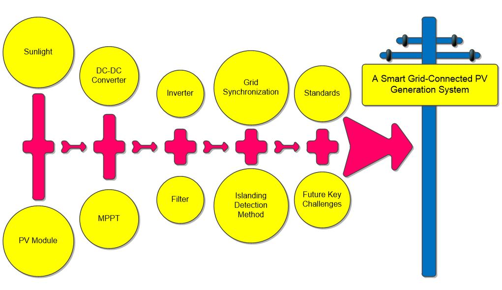
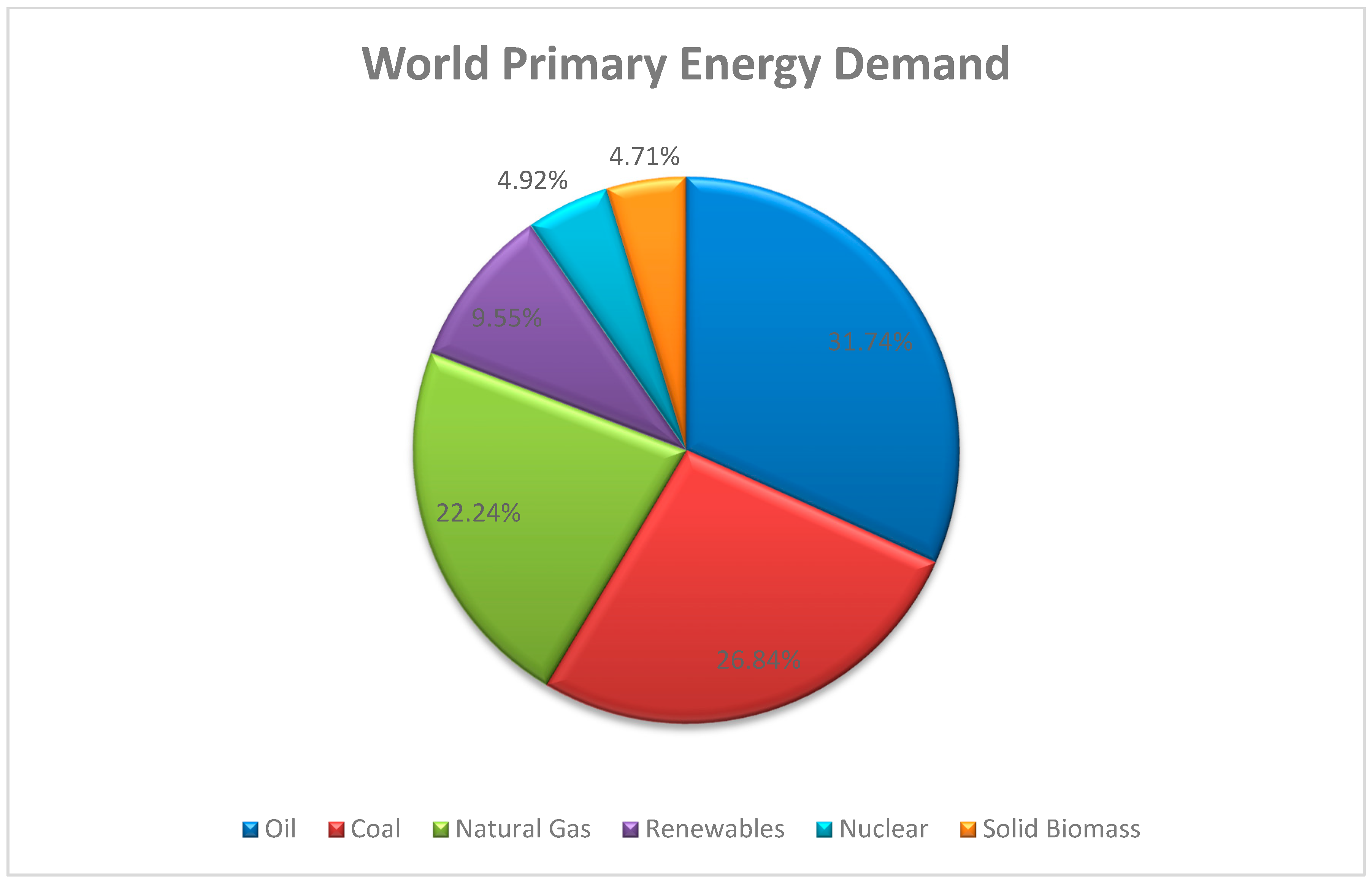
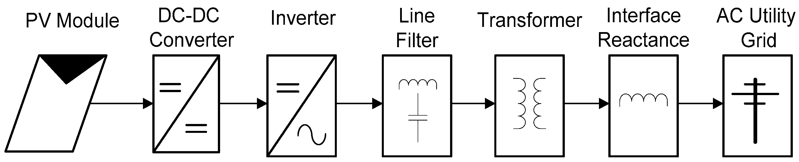
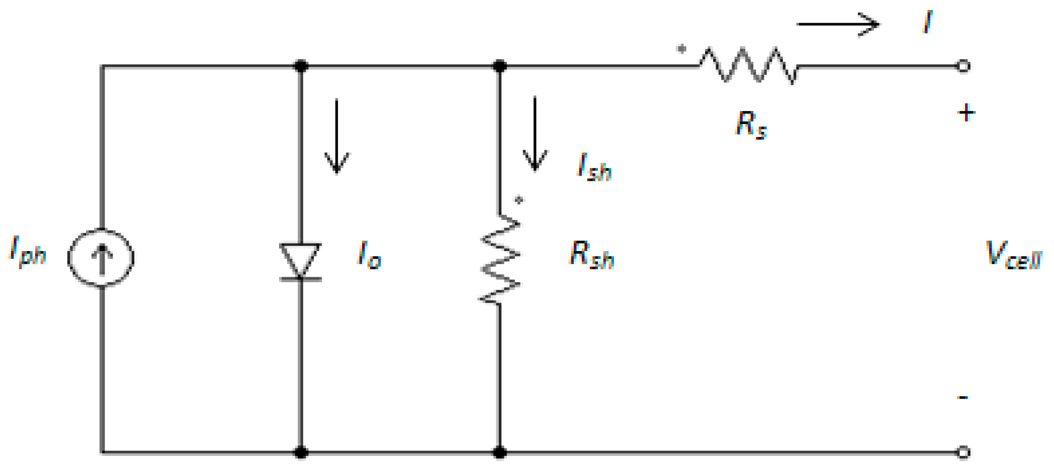
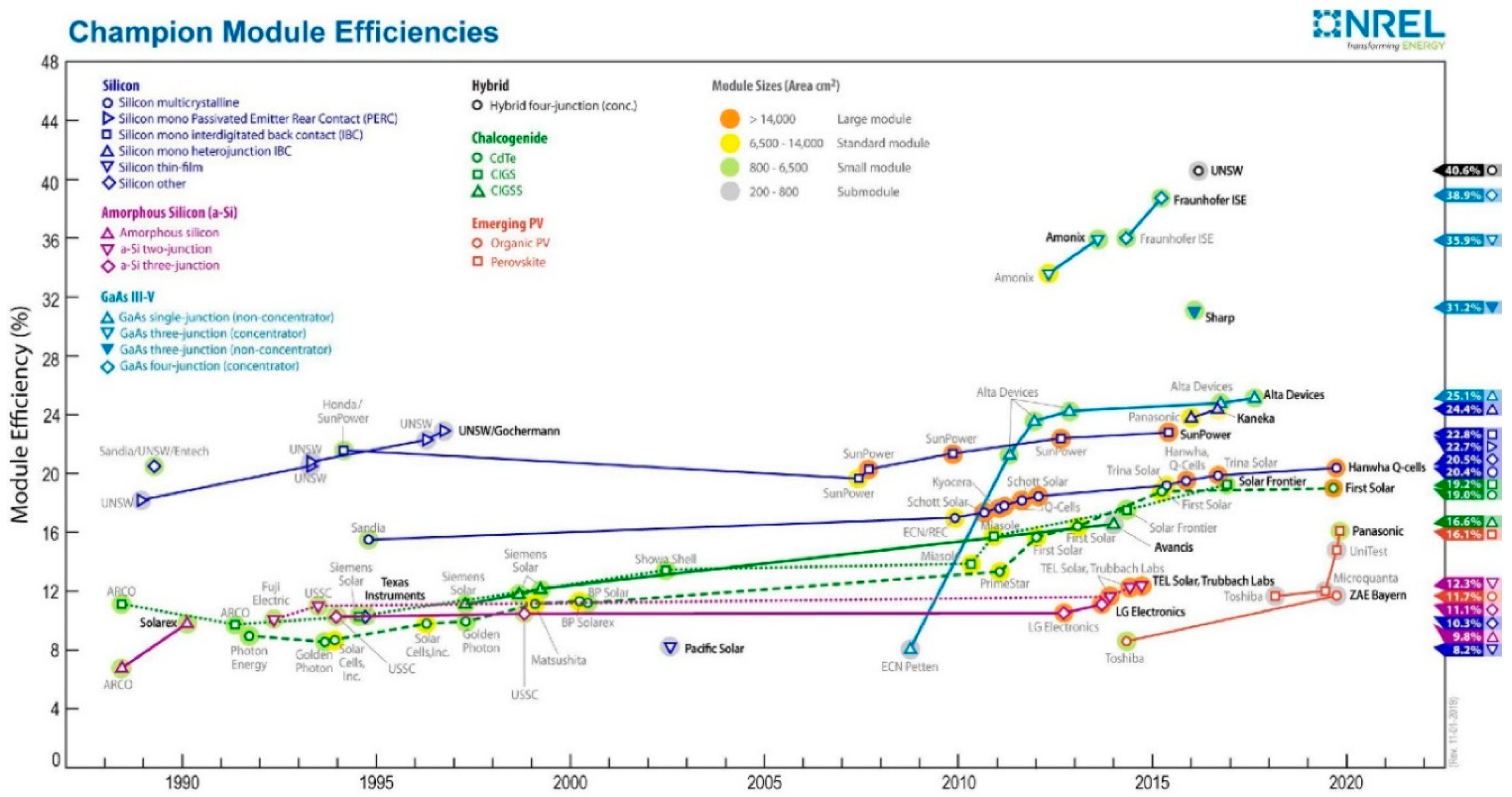
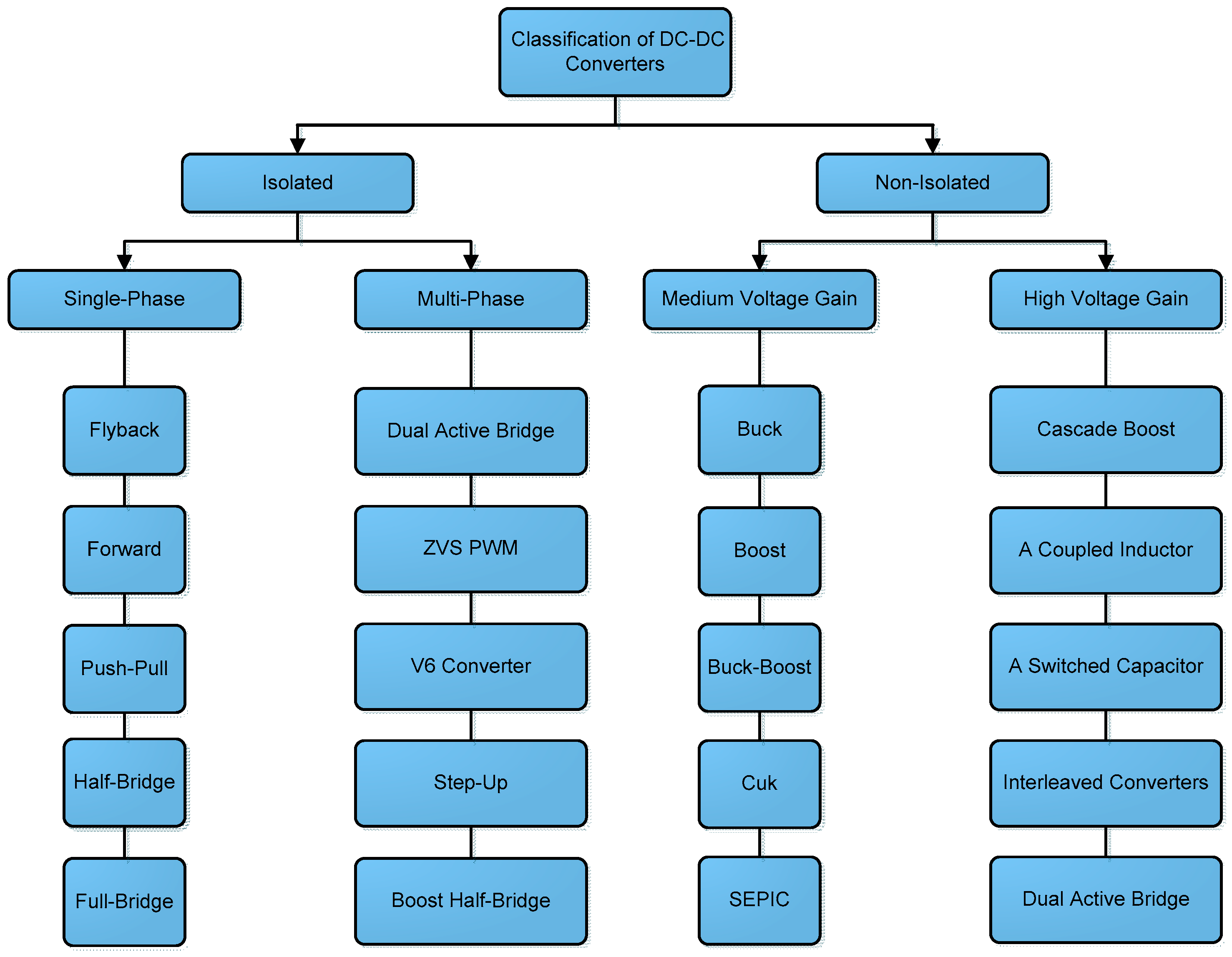
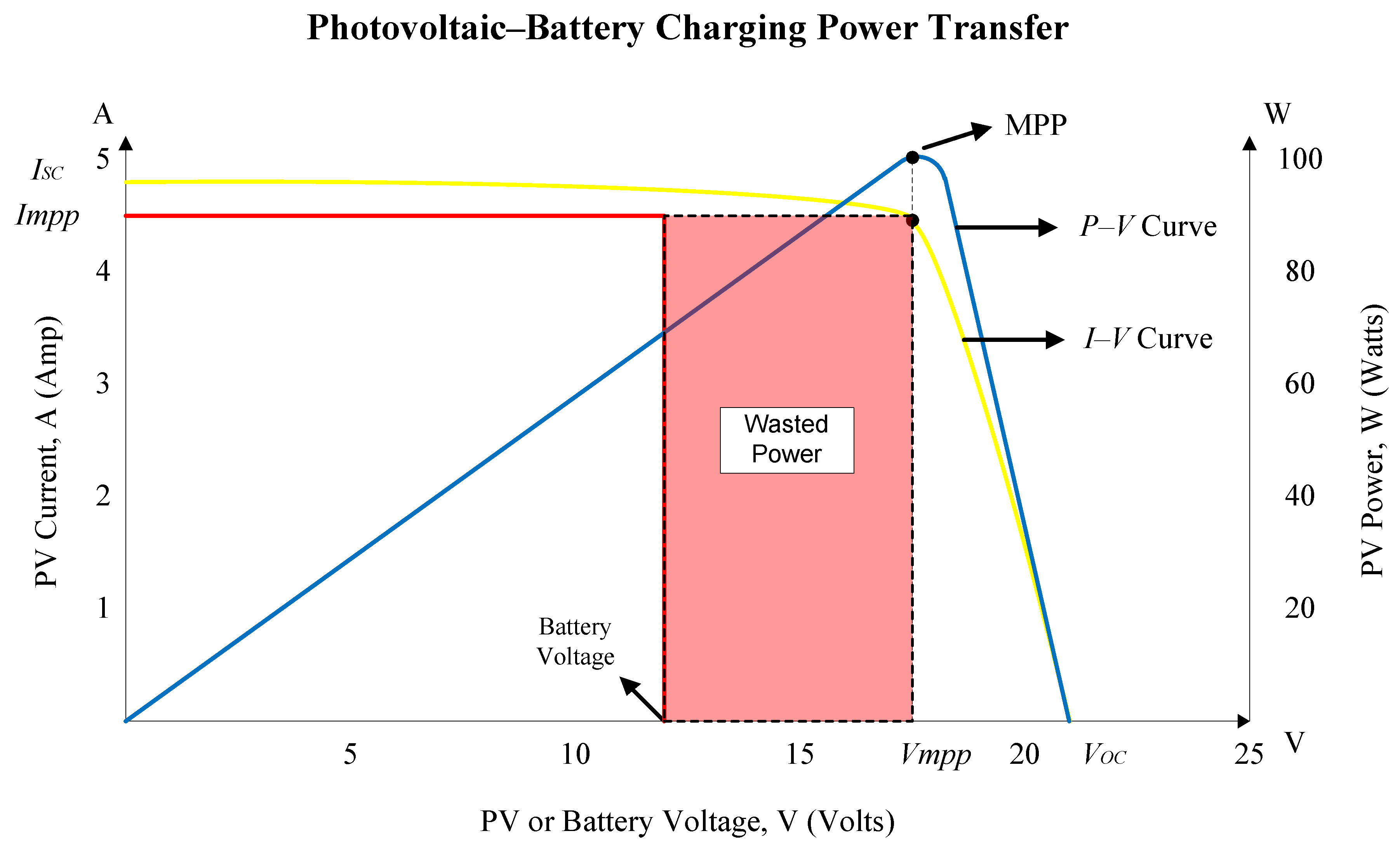
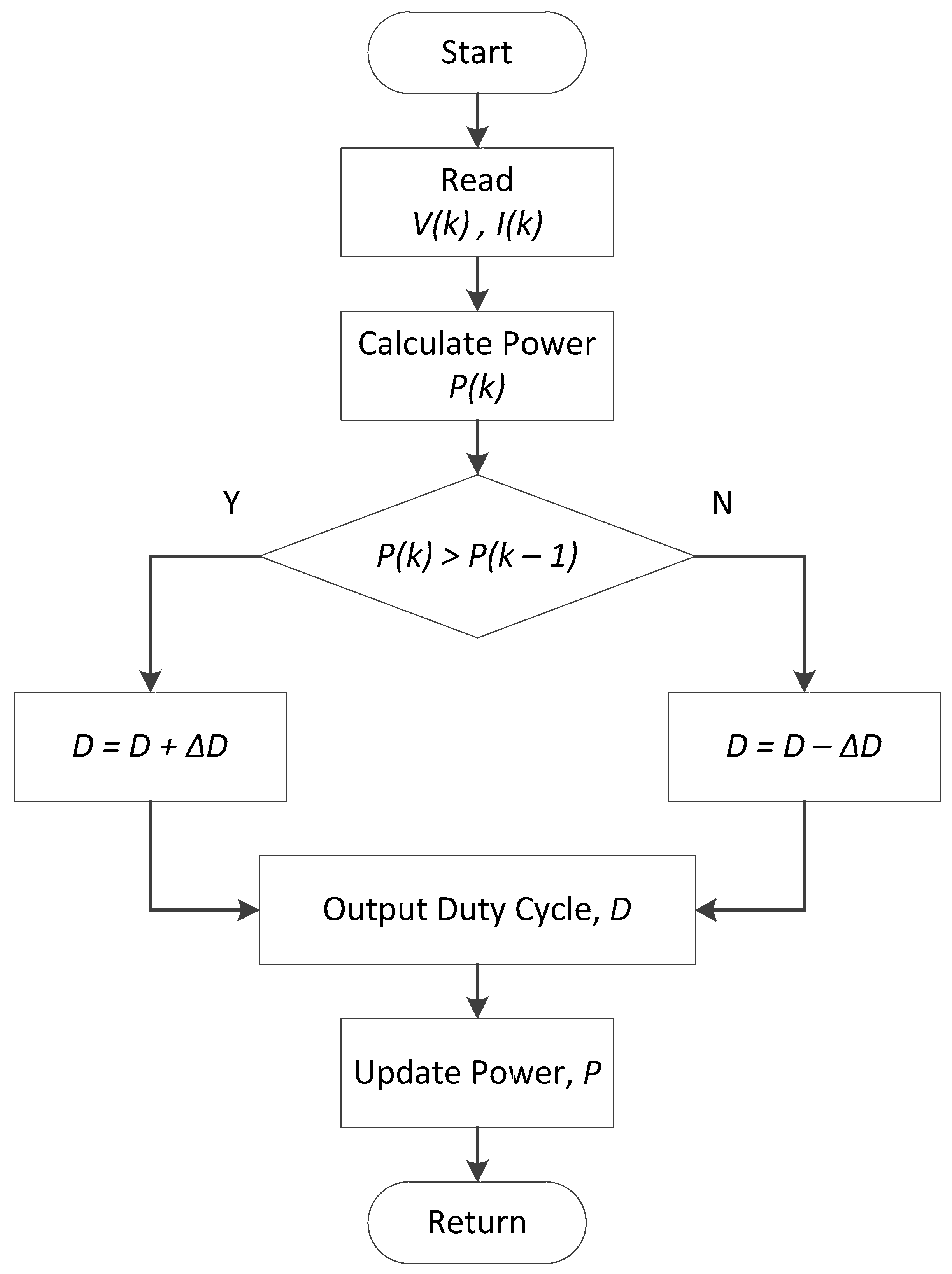
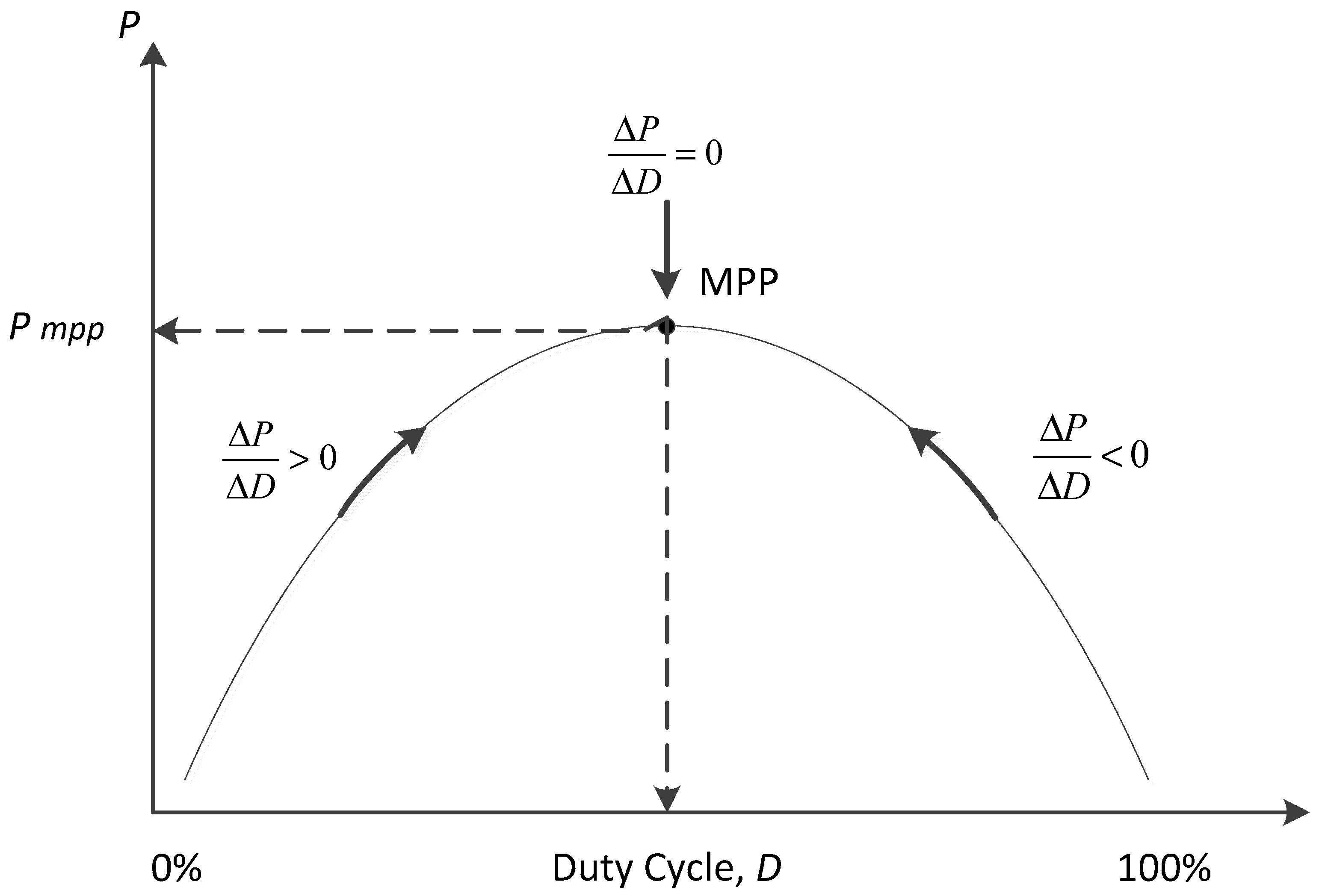
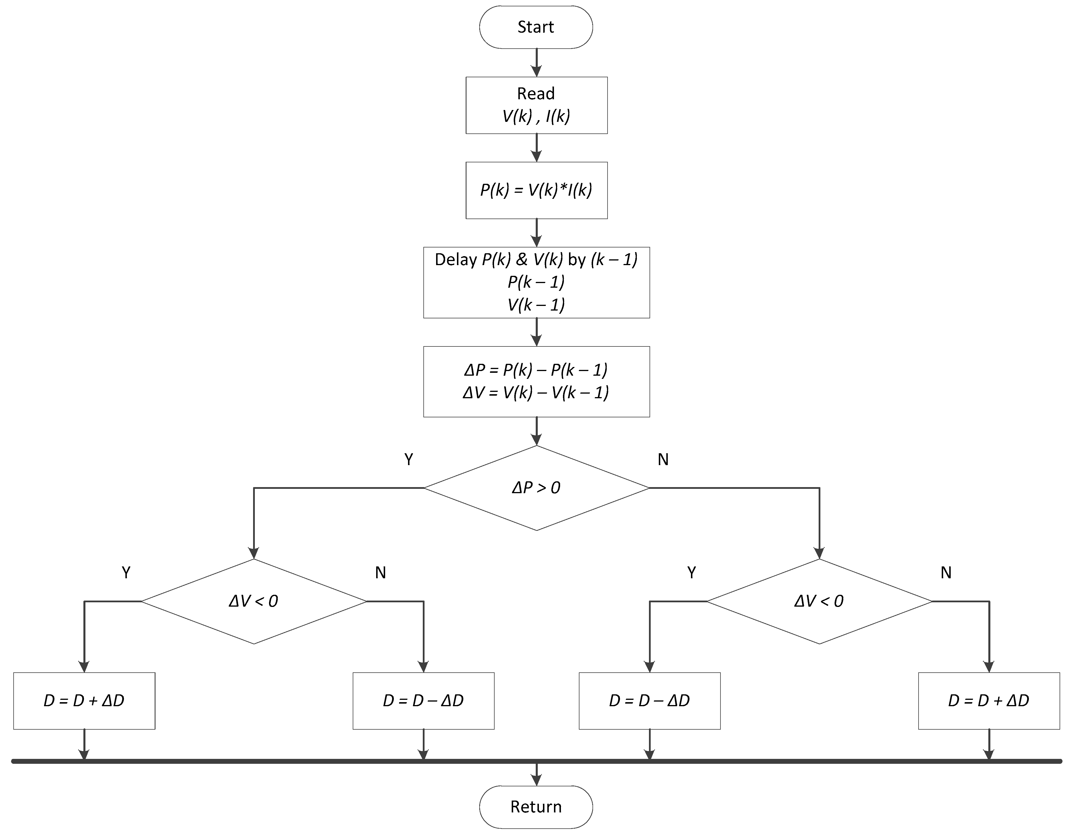
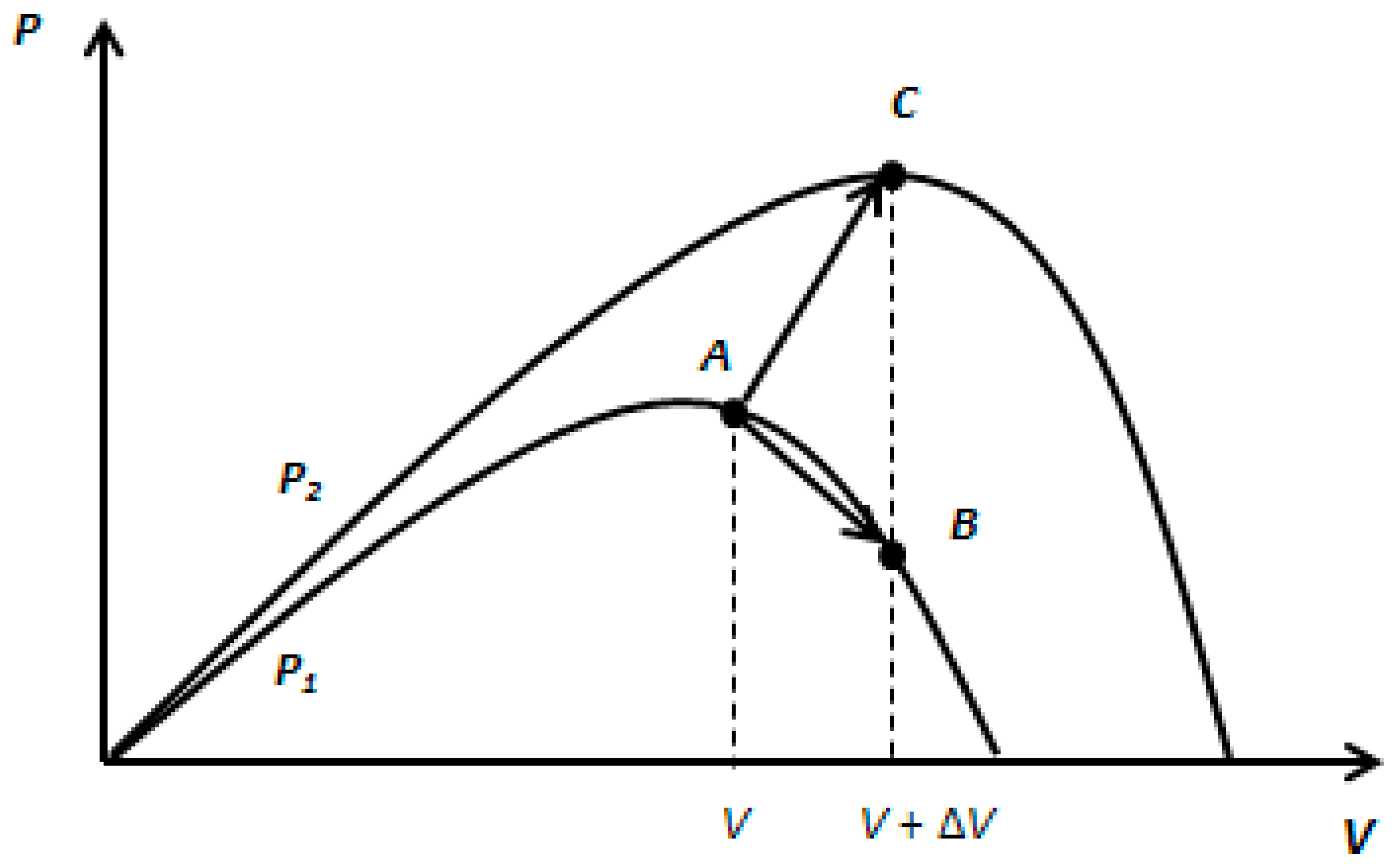
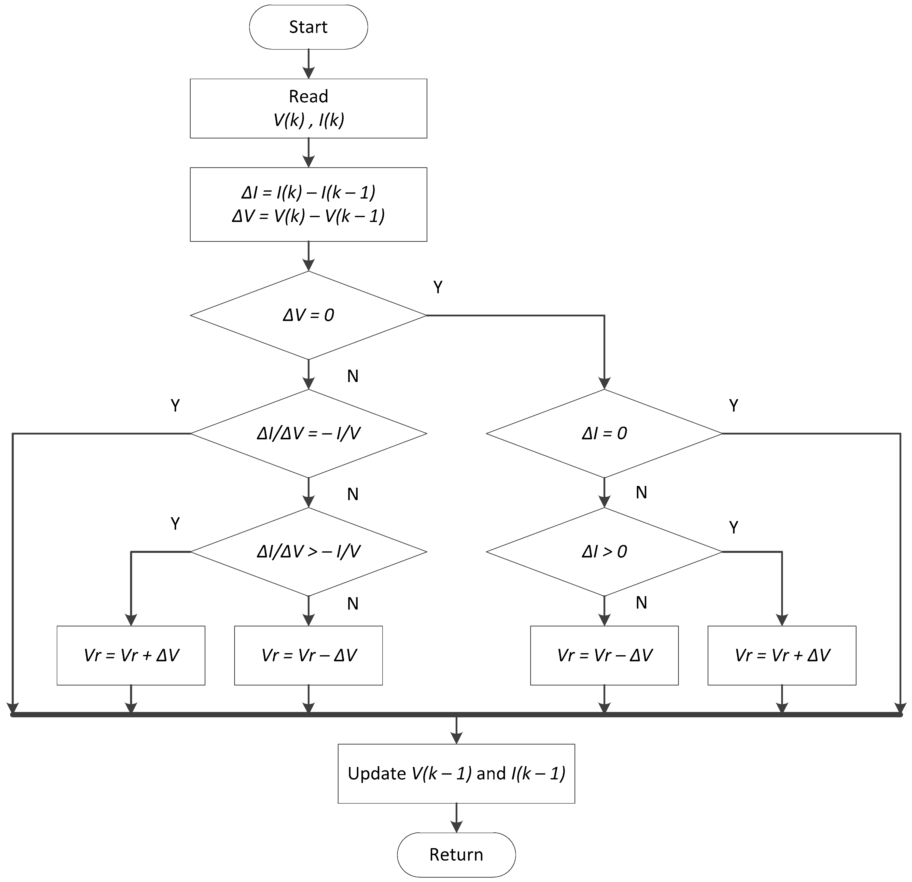
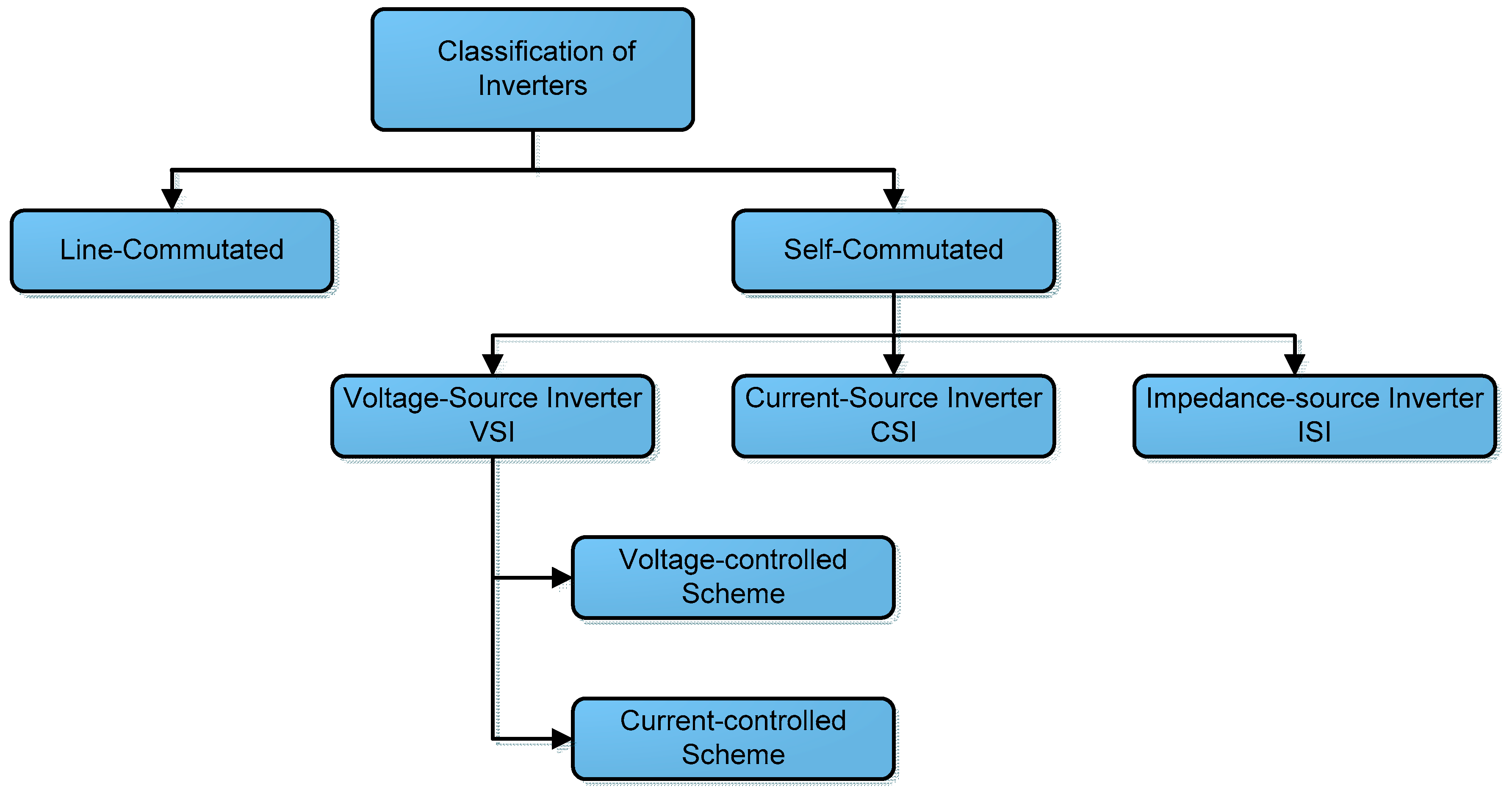
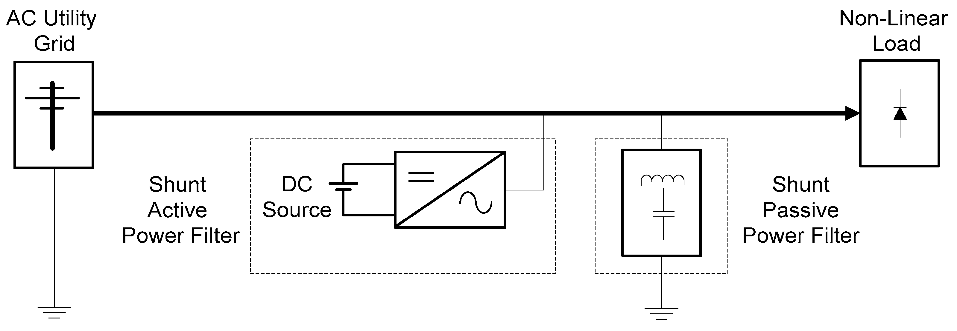
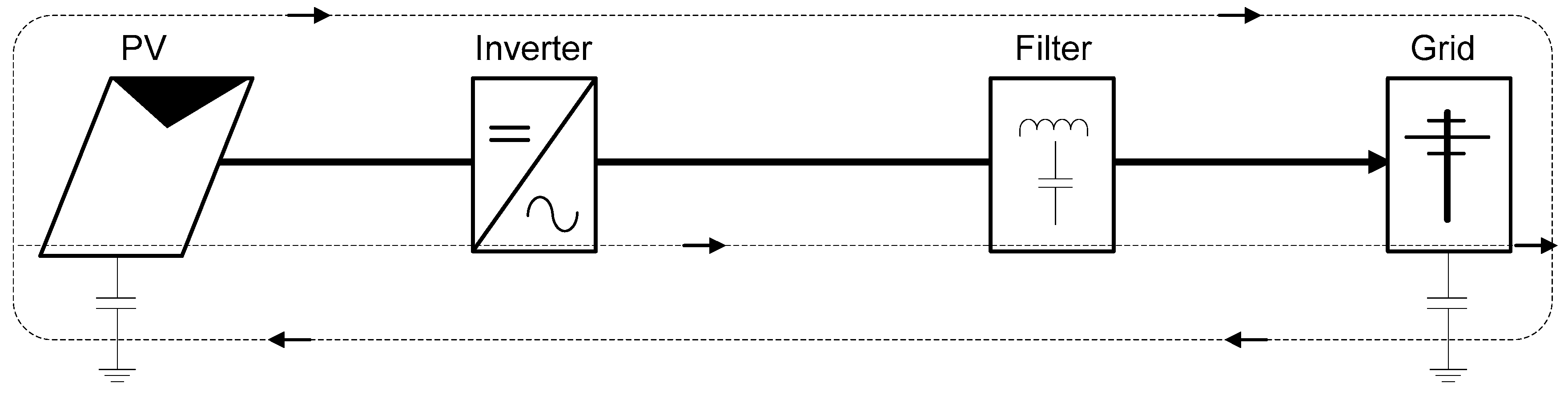
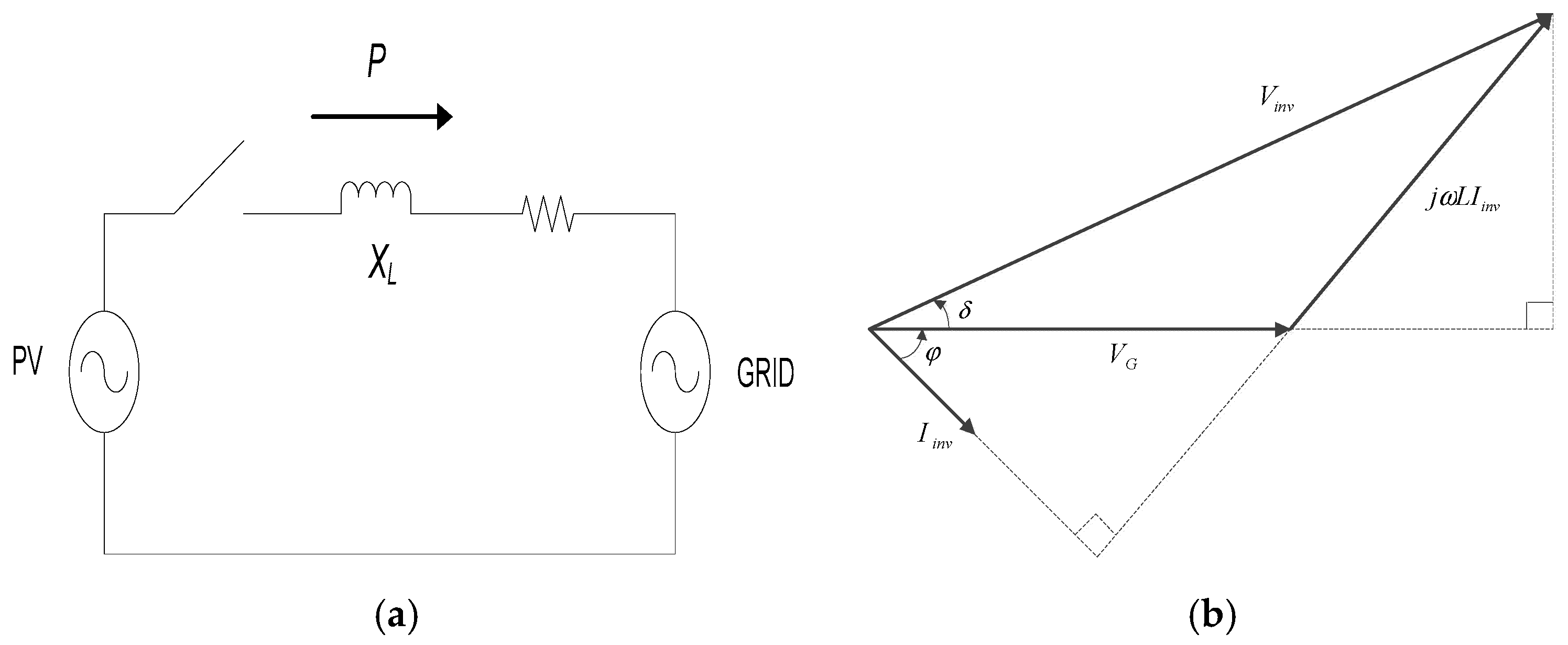
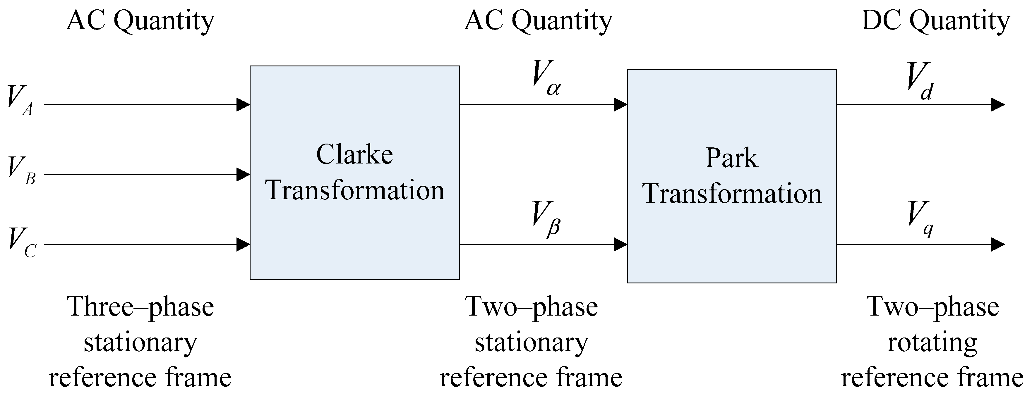
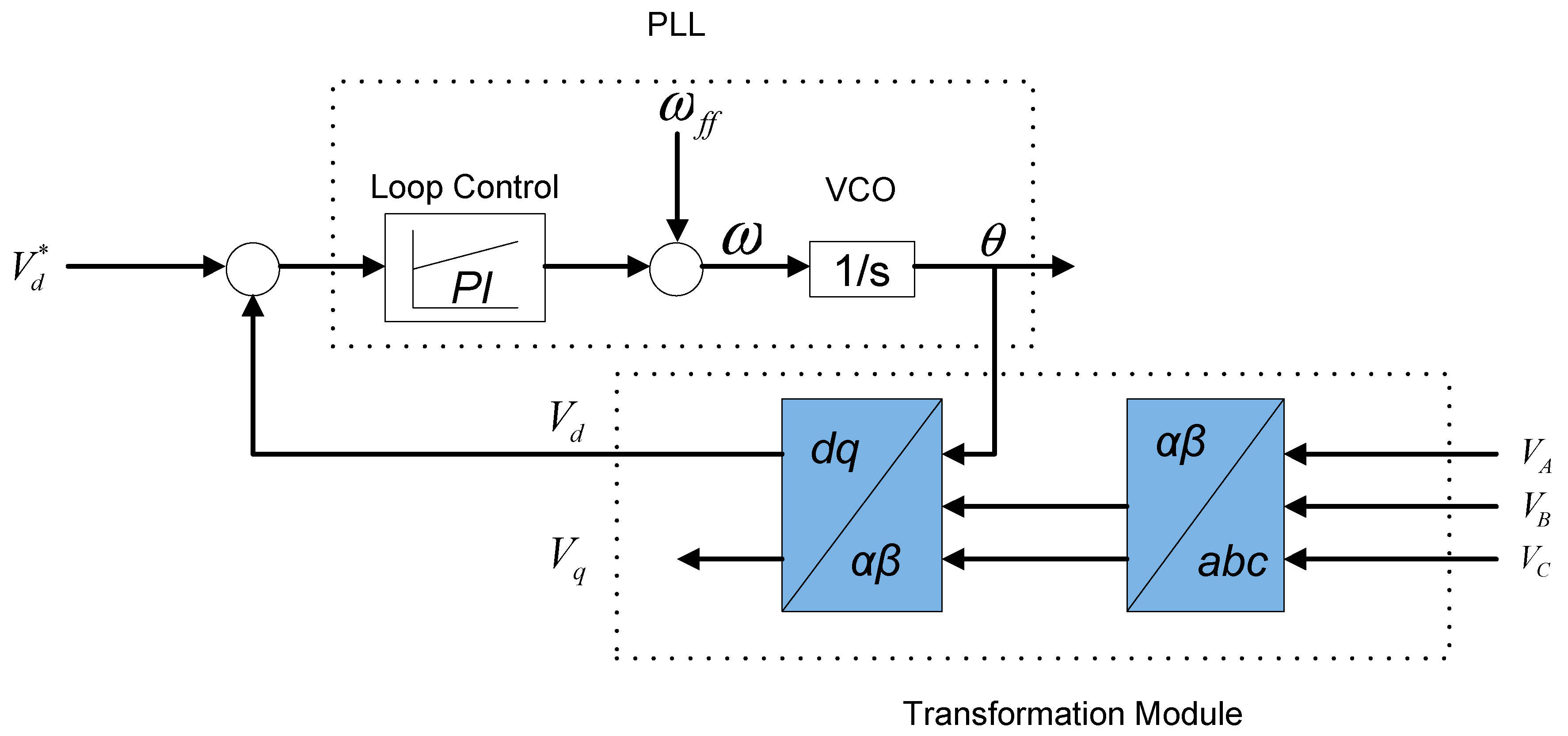
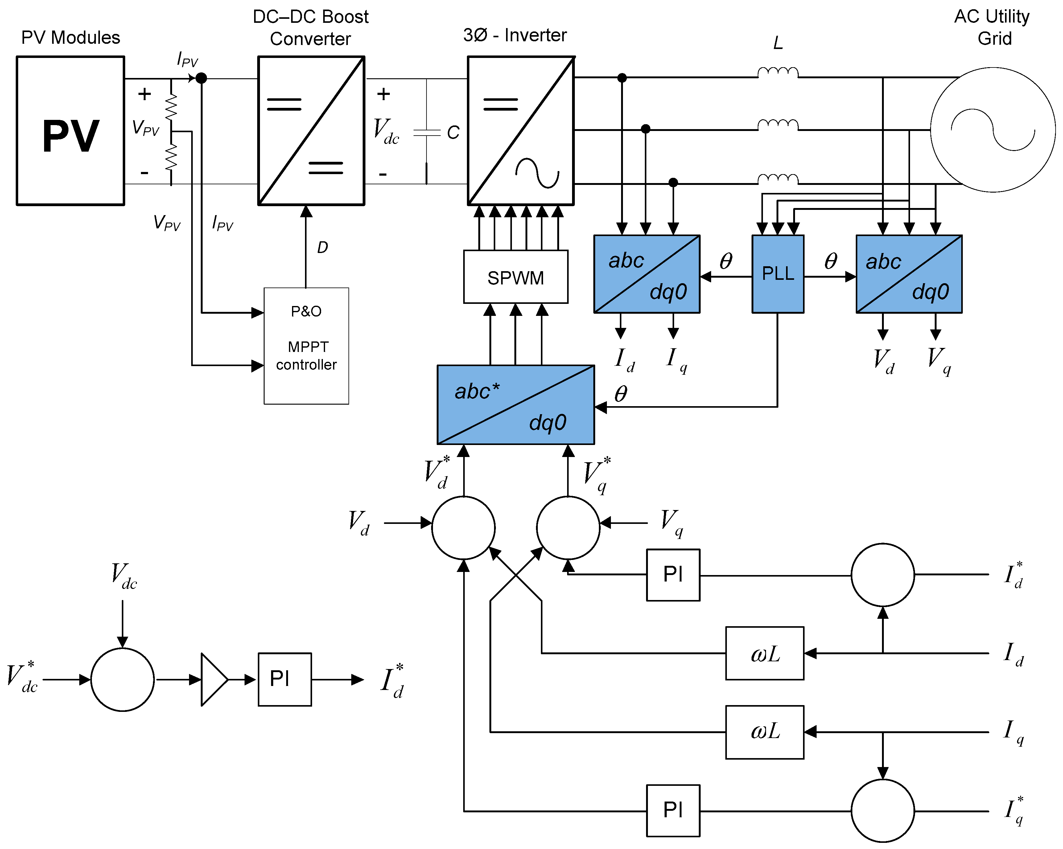
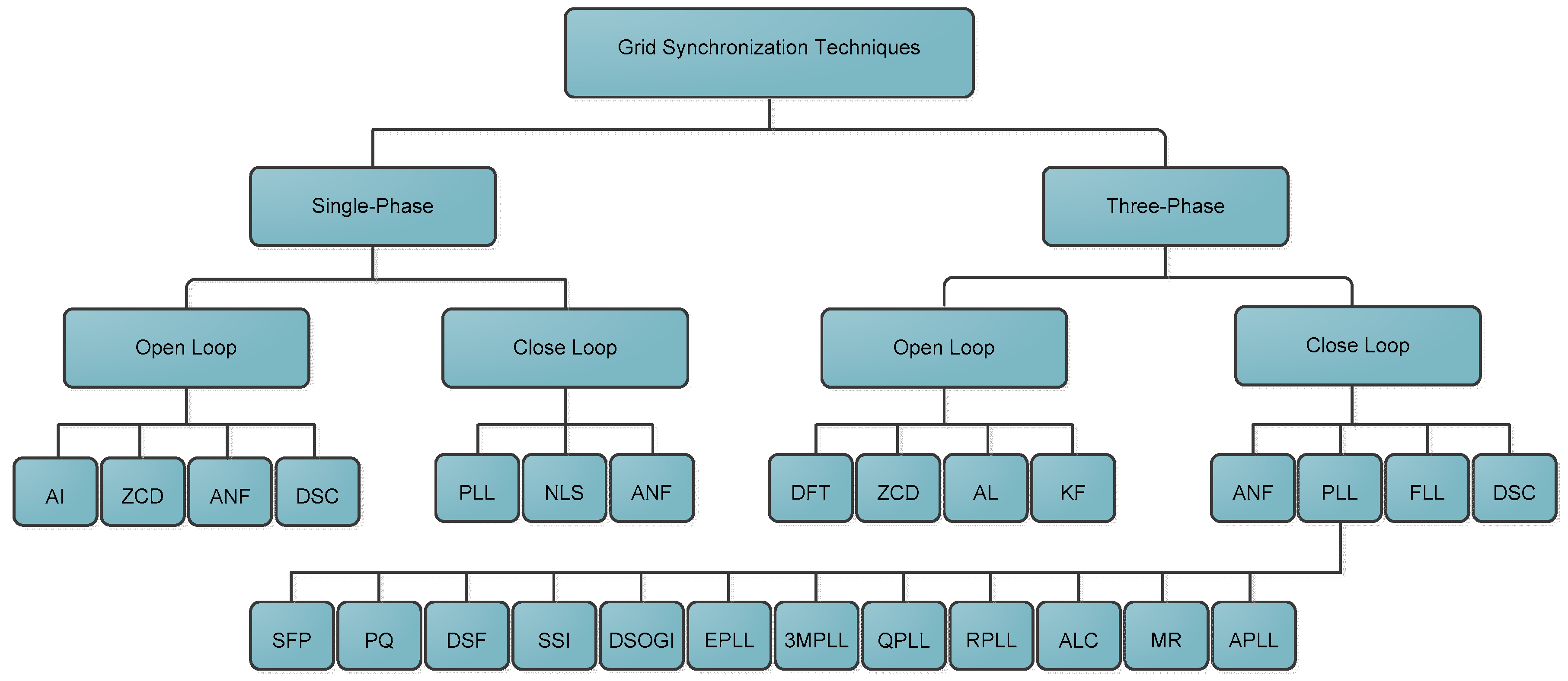
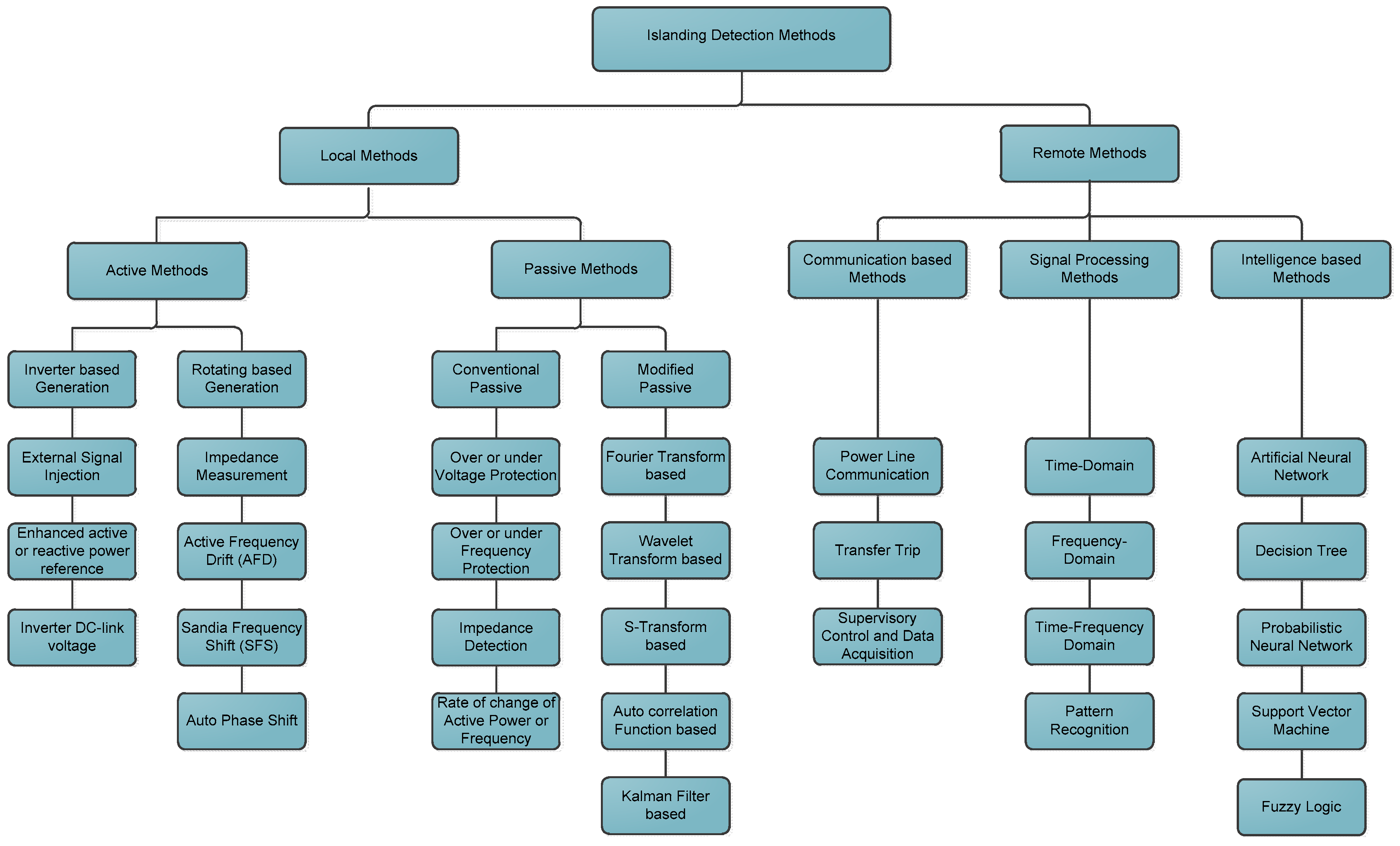
Table 1.
Comparative analysis of review papers covers a similar topic.
| Parameters | 1st Review Paper [12] | 2nd Review Paper [13] | 3rd Review Paper [14] |
|---|---|---|---|
| Scope of the review | 1st paper covers almost similar in content and structure. Details analysis on each section of GPV generation system. | 2nd review paper mostly focused on the modeling of the PV, MPPT methods, converter’s topologies and control algorithms. | 3rd paper presents a review of the recent technological development and trends in the GPV generation system. |
| Advantages | 1st Paper emphasis on prevailing technology along with the techno-economic comparison of commercial available components in the market. | The authors highlight the importance of continuous research in the field of material and power electronics technologies which able to reduce overall cost and increases the system efficiencies. | The main intention of 3rd paper are on the economic growing of GPV generation system as well as the technical challenges posed by mass proliferation. |
| Drawbacks | Details study on PV cell development is not covered. Moreover, it does not stated the recent and future challenges faced by the GPV generation system. In addition to that, there is no mention on fire protection and disposable standard. | Recent update on PV cell, MPPT technique not well reported. The description on the types of filters, switching techniques, grid synchronization and islanding detection methods were also missing. | 3rd paper merely focuses on PV installation cost and smart inverters. It is totally lack of details explanation on the other sub-topics within the GPV generation system. |
| Focus Group | Young Researcher PV Researcher Project Engineer | Young Researcher PV Researcher Project Engineer | Young Researcher PV Researcher |
Table 2.
Comparison of major MPPT techniques and their limitations [43,44,45,46,47,48,49,50,51,52,53,54,55,56,57,58,59,60,61,62,63,64].
| MPPT Technique | Parameters | ||||||
|---|---|---|---|---|---|---|---|
| PV Array Dependent | Analog or Digital | Convergence Speed | Implementation Complexity | Input Sensors | Tracking Approach | Under Partial Shading Condition | |
| HC | No | Both | Slow | Low | V, I | Iteration | Ineffective |
| P&O | No | Both | Medium | Low | V, I | Iteration | Ineffective |
| INC | No | Digital | Varies | Medium | V, I | Mathematical Calculation | Ineffective |
| FOCV | Yes | Both | Medium | Low | V | Constant Parameters | Ineffective |
| FSCC | Yes | Both | Medium | Medium | I | Constant Parameters | Ineffective |
| RCC | No | Analog | Fast | Medium | V, I | Mathematical Calculation | Ineffective |
| A voltage or Current Sweep | Yes | Digital | Slow | High | V, I | Mathematical Calculation | Ineffective |
| DC-Link Capacitor Droop | No | Both | Medium | Low | V | Iteration | Ineffective |
| The load I or V Maximization | No | Analog | Fast | Low | V, I | Measurement and Comparison | Ineffective |
| dP/dV or dP/dI Feedback Control | No | Digital | Fast | Medium | V & I | Mathematical Calculation | Ineffective |
| FL | Yes | Digital | Fast | High | Varies | Intelligent Prediction | Partially Effective |
| ANN | Yes | Digital | Fast | High | T, G & I | Intelligent Prediction | Partially Effective |
| PSO | No | Digital | Fast | High | V & I | Soft Computing | Effective |
| GA | No | Digital | Fast | High | Varies | Soft Computing | Effective |
| RMO | No | Digital | Fast | Medium | Varies | Soft Computing | Effective |
| BSCA | No | Digital | Medium | High | V, I,G,T | Soft Computing | Effective |
| ACO | No | Digital | Fast | High | V, I | Soft Computing | Effective |
| CS | No | Digital | Fast | High | V | Soft Computing | Effective |
| SSA | No | Digital | Fast | High | V, I | Soft Computing | Effective |
| GWO | No | Digital | Fast | High | V, I | Soft Computing | Effective |
| Parameters | Description |
|---|---|
| Phase Sequence | The phase sequence or phase rotation of the three-phase inverter must be matching as the phase sequence of the three phases of the grid. |
| Voltage Magnitude | The magnitude of the sinusoidal voltage produced by the inverter must be equivalent to the magnitude of the sinusoidal voltage of the grid |
| Frequency | The frequency of the sinusoidal voltage produced by the inverter must be equal to the frequency of the sinusoidal voltage of the grid. |
| Phase Angle | The phase angle between the sinusoidal voltages produced by the inverter and the sinusoidal voltage generated by the grid must be zero. |
| Parameter | The Direction of Power Flow | |
|---|---|---|
| Phase Difference, | The real power, flows from inverter to Grid | |
| The real power, flows from Grid to Inverter | ||
| Voltage Magnitude, | The reactive power, flows from Inverter to Grid | |
| The reactive power, flows from Grid to Inverter | ||
Table 5.
Future key challenges on GPV generation system [100,101,102,103,104,105,106,107,108,109,110,111,112,113,114,115,116,117,118,119,120,121,122,123,124,125,126,127,128,129,130,131].
| Main Components on GPV Generation System | |||||||
|---|---|---|---|---|---|---|---|
| PV Module | MPPT | DC-DC Converter | Inverter | Line Filter | Synchronization Control Technique | Coupling Transformer | Interface Impedance |
| Material on high energy conversion efficiency and low-cost implementation | The exact and variable step size of Duty Cycle and Voltage. | High gain DC-DC Converters. | DC-AC Ratio Optimization | Impact on power quality, protection, and operation of distribution feeders. | Protection scheme against Islanding, transient fault condition, rapidly changing reactive power demand by grid. | The single-stage transformer-less conversion system. | An optimization technique for Inverter-Grid Interface Impedance. |
| Protection against the high intensity of irradiation, fire hazard, haze, and extreme climatic changes | The exact and variable step size of the perturbation period. | Resonant Converters with soft-switching technique. | Three-level neutral point clamp Topologies. | Hybrid Passive Filter configurations. | Supervisor controller to control of multiple distributed generation plants. | High-Frequency (HF) Transformer. | Characteristic of interface impedance for maximum power transfer. |
| Potential Induced Degradation (PID) effect | Partially shaded condition. | Multi-level DC-DC Converters. | Multi-level Modular Central Inverter. | Double line frequency pulsating power issue. | Smart grid and smart energy storage system. | Effect of Core Losses and Saturation to Power transfer. | |
| Development of advance Sun Tracking PV Panel | Sensor-less MPPT Algorithm. | Multiple Input Multiple Output DC-DC Converters. | Modulation control technique. | Shunt Active Power Filter for Three-phase system. | Control strategy for Unbalanced, distorted and Non-linear load conditions. | Leakage current in Transformer-less system. | |
| Booster application to intensify the Irradiation and Temperature | The introduction of artificial intelligence i.e., Heuristic search methods. | Control technique for non-isolated DC-DC Converters. | Single-stage Transformer-less Inverters. | Hybrid Active and Passive Filter configuration. | The introduction of artificial intelligence in the synchronization of the grid-connected PV system. | Study on the Construction and Core Design of Transformer. | |
© 2020 by the authors. Licensee MDPI, Basel, Switzerland. This article is an open access article distributed under the terms and conditions of the Creative Commons Attribution (CC BY) license (http://creativecommons.org/licenses/by/4.0/).
Share and Cite
MDPI and ACS Style
Mohamed Hariri, M.H.; Mat Desa, M.K.; Masri, S.; Mohd Zainuri, M.A.A. Grid-Connected PV Generation System—Components and Challenges: A Review. Energies 2020, 13, 4279. https://doi.org/10.3390/en13174279
AMA Style
Mohamed Hariri MH, Mat Desa MK, Masri S, Mohd Zainuri MAA. Grid-Connected PV Generation System—Components and Challenges: A Review. Energies. 2020; 13(17):4279. https://doi.org/10.3390/en13174279
Chicago/Turabian StyleMohamed Hariri, Muhammad Hafeez, Mohd Khairunaz Mat Desa, Syafrudin Masri, and Muhammad Ammirrul Atiqi Mohd Zainuri. 2020. "Grid-Connected PV Generation System—Components and Challenges: A Review" Energies 13, no. 17: 4279. https://doi.org/10.3390/en13174279
Note that from the first issue of 2016, this journal uses article numbers instead of page numbers. See further details here.