Numerical Analysis of the Deformation Performance of Monopile under Wave and Current Load
by
 ,
,
Libo Chen
1, 
Xiaoyan Yang
1,
Lichen Li
1,
Wenbing Wu
1,2,3,4,*,
M. Hesham El Naggar
1,3,
Kuihua Wang
3 and
Jinyong Chen
1 1
Engineering Research Center of Rock-Soil Drilling & Excavation and Protection, Ministry of Education, Faculty of Engineering, China University of Geosciences, Wuhan 430074, China
2
Research Center of Coastal Urban Geotechnical Engineering, Zhejiang University, Hangzhou 310058, China
3
Geotechnical Research Centre, Department of Civil and Environmental Engineering, Western University, London, ON N6A 5B9, Canada
4
Zhejiang Institute, China University of Geosciences, Hangzhou 311305, China
*
Author to whom correspondence should be addressed.
Energies 2020, 13(23), 6431; https://doi.org/10.3390/en13236431
Submission received: 2 November 2020
/
Revised: 27 November 2020
/
Accepted: 1 December 2020
/
Published: 4 December 2020
(This article belongs to the Section A3: Wind, Wave and Tidal Energy)
Abstract
:The research on the deformation mechanism of monopile foundation supporting offshore wind turbines is significant to optimize the design of a monopile foundation under wave and current load. In this paper, a three-dimensional wave-pile-soil coupling finite element model is proposed to investigate the deformation mechanism of monopile undercurrent and fifth-order Stokes wave. Different from the conventional assumption that there is no slip at the pile-soil interface, Frictional contact is set to simulate the relative movement between monopile and soil. Numerical results indicate that under extreme environmental conditions, the monopile foundation sways within a certain range and the maximum displacement in the loading direction is 1.3 times the displacement in the reverse direction. A further investigation has been made for a large-diameter pipe pile with various design parameters. The finite element analyses reveal that the most efficient way to reduce the deflection of the pile head is by increasing the embedment depth of the monopile. When the embedment depth is limited, increasing the pile diameter is a more effective way to strengthen the foundation than increasing the wall thickness.
1. Introduction
Over the past several decades, offshore wind turbines (OWT) have grown dramatically and may become an important contributor to global energy production [1]. In addition, the offshore wind industry also shows great ambition towards deep water and far away from the coast, which makes the substructures of offshore wind turbines bear significantly higher overturning moment under wave loads [2]. Considering the environmental conditions, many types of substructures for offshore wind turbines have been developed, in which monopile is the most commonly-used, accounting for 80% of all substructures installed so far [3], which contain a transition piece and is similar to onshore counterparts.
During the operation, the monopile foundations of OWT are exposed to several types of environmental loads, which attract a number of scholars to investigate their complex behaviors. Considering the limitations of analytical analysis and experimental study, numerical analysis plays an important role in the study of offshore foundation response. The traditional methods for designing and optimizing monopiles were recommended by DNV-GL (Høvik, Norway) [4], which were based on API (American Petroleum Institute) [5] design guidelines. Both guidelines adopted a Winkler foundation model where the lateral soil reaction at a given depth was described by decoupled non-linear ‘p-y’ curves. However, the above methods are based on load tests conducted on piles with small diameter (i.e., <1 m), and may not be appropriate for large-diameter pile foundations nowadays. In recent years, the three-dimensional (3D) finite element method (FEM) has been widely utilized in research and engineering to simulate complex problems involving soil-structure interaction. Several scholars [6,7,8] have conducted a 3D finite element method to analyze the performance of large-diameter monopiles. Their results show that compared with API ‘p-y’ method, the 3D FEM is more accurate in studying the response of monopiles.
Gupta and Basu [9], Lesny and Wiemann [10], Neenu and Alice [11] utilized 3D FEM packages to analyze the deformation performance of large-diameter monopiles and obtained some new findings, but the above numerical models were not validated against monopile load tests. Gerry et al. [12] presented a methodology for accurately modeling monopile behavior, the results showed that the contribution of each component to the overall lateral resistance is related to pile geometry. Yang et al. [13] developed a user subroutine of degradation stiffness modeled coupled with 3D FEM to investigate the performance of OWT monopiles, and found that the rotation point is located at a depth of 0.7 times embedment depth of monopile. Ma et al. [14] considered the long-term effect of monopile and reflected that increasing wall thickness could lead to a remarkable decrease in deflection of pile head, but changing pile diameter did not make an obvious effect in several cases. In the former studies, the calculation of wave loads acting on monopile was based on Morison’s equation which was based on the linear Airy wave theory and field test results of small-diameter monopiles [15,16]. Moreover, only maximum wave load were considered in these studies and the dynamic process of wave loads were ignored. Therefore, it is necessary to study the structural behavior of OWT through a progressive numerical model for more accurate design recommendations.
Tong et al. [17] and Chen et al. [18] calculated wave loads based on the fluid-solid coupling model, but these studies only focused on the effects of wave loads on the seabed and ignored the soil inside the monopiles. In light of this, this paper aims to propose a wave-pile-soil coupling 3D finite element model to investigate the deformation mechanism of monopile-soil system, and explore the influence of several geometrical parameters on the response of monopile foundation under extreme marine condition. Through the establishment of fluid-solid coupling contact surface on the pile surface, the mechanical information between the fluid and the solid is transmitted, and the numerical analyses are carried out to reveal the deformation characteristics of the monopile foundation. After validating the basic model, the displacement of pile-soil system in the time domain and the effects of wall thickness, pile diameter and embedment depth on the deformation characteristics of the pile are also investigated.
2. Numerical Model
In this study, the integrated coupling numerical model in ANSYS WORKBENCH (ANSYS, Inc., Canonsburg, PA, USA) is utilized to analyze the performance of offshore monopile. The coupling model consists of two parts, the fluid model and monopile-soil model. The fluid model is established in Fluent 3D (ANSYS, Inc., Canonsburg, PA, USA) and solved by computational fluid dynamics (CFD); the monopile-soil model is developed in ANSYS Parametric Design Language (APDL) and solved by FEM. In this section the wave model is introduced first, then, the monopile-soil model. Finally, the whole wave-monopile-soil model is presented.
Figure 1 presents a sketch of the wave-monopile-soil model. The wave and current are generated at the inlet and dissipated at the outlet. The monopile is located in the middle of the domain with an embedment depth of , and the part of pile submerged in water is subjected to the wave and current. The contact surfaces between pile and pile surrounding soil, and between pile and pile end soil are modelled with a frictional contact model.
2.1. Wave Model
The governing equations for simulating the motion of incompressible Newtonian fluid due to waves are based on the conservation equations of mass and momentum conservation, which can be described by the Reynolds-averaged Navier-Stokes equations as [17]:
where, ; and denote the fluid velocity and fluid pressure, respectively; is time; represents the gravitational acceleration vector and is the Reynolds stress tensor, which is defined as:
in which, is the mean strain rate tensor; denotes the dynamic viscosity; is the turbulence kinetic energy (TKE) and represents the Kronecker delta.
2.2. Monopile-Soil Model
To comprehensively analyze the monopile-soil interaction of wind turbine foundation, a 3D finite element model is established by using APDL. As shown in Figure 2, the monopile-soil model consists of three parts, i.e., the soil inside the pile, the soil around pile, and the monopile.
The soil and monopile are constructed using 8-noded Hexa elements. The monopile is assumed to be an elastic material, while the soil is assumed to be elastic-plastic following the Mohr-Coulomb failure criterion.
The contact relationship between pile and soil is defined as friction contact. In this setting, the contacting geometries can carry up to a certain amount of shear stress at their interface before they begin to slide relative to each other, which is known as the ‘sticking’ state. The present model defines equivalent shear stress at which sliding on the geometry will slide relative to each other with the friction coefficient 0.5.
2.3. Wave-Monopile-Soil Coupling Model
Different from traditional methods of using Morrison’s equation to calculate the force applying on a monopile, this paper utilizes the FLUENT 3D Multiphase function to establish a wave model. The wave theory selected in this paper is the fifth-order Stokes wave theory which is widely used in marine engineering wave simulation. The monopile-soil model is founded in the APDL, and its rationality of the assumption that the present model ignores the influence of fluid on the monopile will be verified in Section 3.1.
For the monopile with a large diameter, the height of the soil inside the pile can be reasonably assumed to be consistent with the height of soil outside the pile [22,23]. In order to focus on the effect of wave and current on the pile, this model assumes soil to be solid and ignore the effect of waves on the seabed.
As shown in Figure 3, the integrated model consisting of wave model (Figure 3b) and monopile-soil model (Figure 3c) is combined and calculated by ANSYS coupling system. During the combination of the integrated model, the fluid-solid coupling surface is set on the contact surface of the wave and pile to transmit the displacement and force data from fluid element to solid element.
3. Model Validation
The present model consists of monopile-soil model and wave model, which will be validated against available experiment results in the following two subsections.
3.1. Validation of Monopile-Soil Model
In order to study the response of offshore monopiles under lateral load, Zhu et al. [24] carried out model tests on four tubular piles under lateral loading conditions at different loading height, and one of the tests is introduced to validate the monopile-soil model in this paper. These model tests were mainly for analyzing the mechanical characteristics of monopile with diameter 4–6 m, and the ratio of the normal gravity model to the field test can be determined according to the correspondence between dimensionless parameters. The scale of the introduced model test is 1:30.3, and the model rigid pile is a steel pipe pile. The pile length, outer diameter, wall thickness, embedment depth and loading height are shown in Table 1. The soil is simply represented by a Mohr-Coulomb constitutive model with ideal elastoplastic behavior. The elastoplastic behavior is mainly defined by proportion, Poisson’s ratio, shear modulus, cohesion, and internal friction angle of testing soil as shown in Table 2. In the model test, the monopile was loaded in eleven steps, and the displacement of the pile head was measured step by step. By simulating the lateral static load test of the introduced monopile, the load application position is located at the pile head, and the load application process is the same as the model test.
Figure 4 shows the comparison between the calculated results of pile head deflection and the data of the experiment. It can be seen from Figure 4 that the results of numerical simulation are in good agreement with the results of the model test, which indicates that the rationality of the 3D finite element model of monopile-soil interaction subjected to lateral load.
3.2. Validation of Wave Model
The wave model is validated against the results in wave test cases, which were studied experimentally by Zang et al. [25]. The wave in the experiment is generated by a segmented piston paddle array. The wave gauge is 0.002 m from the upstream surface of the cylinder along the centerline. The parameters in this experiment are as follows: water depth m, wave period s and wave height m.
Considering the fact that the wave field did not form a complete wave within 0–4 s, Figure 5 only shows the free surface elevation at wave gauge in 5–10 s. The results reveal that the peak of elevation in numerical simulation is larger than the counterpart in the experiment, because the structure in the experiment pool has a certain influence on the wave. The results of the numerical model are similar to the experiment data. This indicates that the wave model in this paper is capable to model the wave motion.
4. Response of Monopile Foundation under Extreme Marine Condition
Generally, the monopiles of offshore wind turbines are designed according to the marine conditions at the installation site. In order to analyze the response of a monopile under an extreme marine environment, the marine condition at the Dutch sector of the North Sea, which is 8 km away from the shore of IJmuiden City [26] is simulated in this section. The water depth is 20 m, and the height and period of the 50-year extreme wave are 6.9 m and 7.7 s, respectively. The specific current speed is 0.8 m/s. The diameter and thickness of the monopile are 5 m and 0.07 m, respectively. These typical characteristics of the marine conditions, soil and monopile are summarized in Table 3, Table 4 and Table 5.
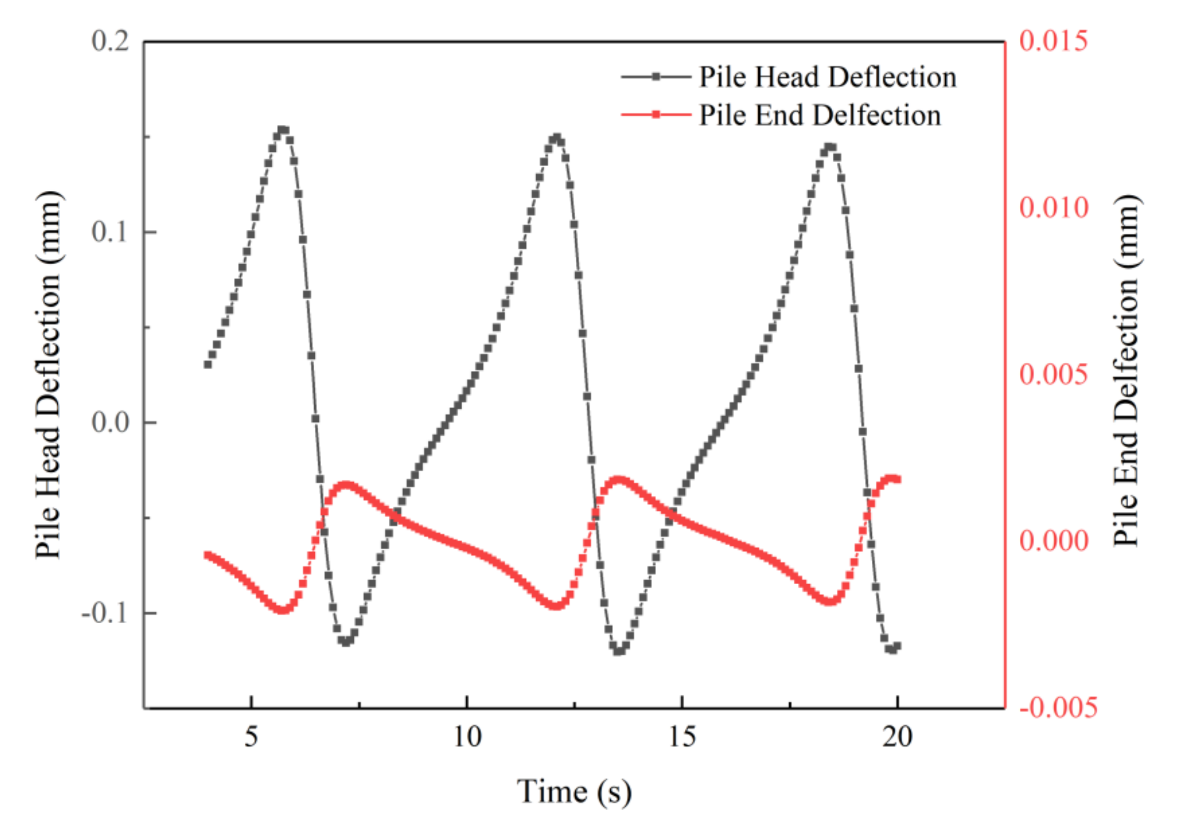
To eliminate the boundary effects, a considerable zone of soil is generated with a height of 30 m, length of 60 m and width of 30 m [27,28]. Different from previous studies [29,30], this paper not only focuses on the deflection of monopile under the maximum wave and current load, but also analyzes the displacement variation during a wave-current action cycle. Under the above environmental conditions, the time domain response of the monopile foundation under wave load is calculated and shown in Figure 6. Under the extreme marine condition, the maximum deflection of pile head is 0.154 mm at 5.7 s, 12.1 s and 18.4 s, while the minimum is −0.116 mm at 7.2 s, 13.7 s and 19.9 s. The pile end reaches its maximum deflection at 7.2 s, 13.7 s and 19.9 s, while reaches the minimum value at 5.7 s, 12.1 s, 19.4 s. It is obviously found that the pile displacement exhibits periodicity under the wave and current load, similar results can be seen in [31]. Where the velocity direction of wave and current is assumed to be positive. In one cycle, the pile head is first generated with a positive deflection along the wave motion direction, and the deflection decreases rapidly after reaching the peak. After returning to the initial position, the pile head quickly moves in the opposite direction, and then reaches the reverse peak, finally returns to the initial position slowly. In addition, during the whole movement process, the pile head is displaced toward the direction of wave motion for most of the time. The forward and reverse deflection amplitudes of the pile head are different, and the maximum positive deflection is 1.32 times the reverse deflection.
Figure 7 illustrates the deflection diagram of the whole monopile body with the displacement amplification factor. For the loading time of 5.7 s shown in Figure 7a, when the pile head reaches the maximum deflection in the loading direction, the pile end reaches the maximum reverse deflection. The opposite situation is shown in Figure 7b for the loading time of 7.2 s. As shown in Figure 7c, at these two moments, the bending and rotation of the pile body coexist, and the monopile presents the characteristics of rigid-flexible pile. Furthermore, the rotation center is 10.5 m below the mud surface. Due to the rotation of the pile, the reciprocating motion of the monopile foundation under the wave and current load will develop pile-soil gap around the pile and threaten the stability of the foundation.
The displacement of soil under extreme wave and current conditions is further analyzed as depicted in Figure 8. It is found from Figure 8a for the loading time of 5.7 s that, when the deflection of the pile head reaches the maximum positive direction, the upper part of the soil within the pile will produce positive displacement, and the lower part will produce reverse displacement. A similar conclusion can be obtained from Figure 8b that, the movement of the upper part of the soil within the pile is in the same direction as the pile head. In addition, the displacement of the soil around the pile should also be paid attention to, for the calculated results show that the displacement of the soil around the pile at the mud surface is significantly greater than that of the soil at the pile end which is less affected by the environmental conditions.
As shown in Figure 8a, the displacement of the pile side soil in the range of 0–10 m in depth and 30–35 m in length reaches 1.5 × 10⁻² mm, which is half of the deflection of the pile at the mud surface. Furthermore, Figure 8b illustrates that the displacement of the soil around the pile in the range of 0–10 m in depth and 25–30 m in length reaches 6.9 × 10⁻³ mm, which is one-third of the displacement of the pile at the mud surface for the loading time 7.2 s. The point with 0 displacement is located at the depth of 11 m, which is similar to the result of the former study [13]. It can be concluded that the soil around the pile within one pile diameter is obviously affected when the monopile foundation reaches the maximum deflection. Therefore, to optimize the bearing performance of the monopile foundation in the marine environment, it is important to reduce the deflection of monopile at the mud surface during operation.
5. Parametric Study
Because the actual offshore engineering is limited by the site conditions, installation equipment and design requirements, various combinations of monopile design parameters will be carried out to obtain the optimal design scheme. Using the present 3D FEM model, a parametric study is conducted to analyze the effect of several design parameters, including pile embedment depth (), wall thickness of tubular pile (), and pile diameter (D), on the horizontal deformation characteristics of a monopile foundation. By changing two parameters and keeping others constant, the optimal design of monopile under different conditions is analyzed. The conclusions of this section can provide references and suggestions for marine engineering.
5.1. Effect of Pile Diameter and Wall Thickness
During the installation of the monopile foundation for OWT, sometimes the embedment part of the monopile cannot exceed a certain depth because of the limitation of equipment and cost. Setting the embedment depth of monopile as 16 m, the influence of pile diameter and wall thickness on the lateral bearing characteristics of the monopile foundation is systematically studied in this section. The pile diameter is assumed to be 4 m, 4.5 m, 5 m, 5.5 m, 6 m, and the wall thickness is 0.06 m, 0.065 m, 0.07 m, 0.075 m, 0.08 m [32,33], respectively. A total of 25 groups of numerical calculations are carried out, and the results are shown in Figure 9. It is found that the deflection of the pile head can be effectively reduced by increasing the pile diameter or wall thickness when the embedment depth of the monopile is fixed. For the pile wall thickness of 0.07 m, when the pile diameter increases from 4 m to 6 m, the deflection of the pile head is reduced from 0.181 mm to 0.143 mm, with a reduction of 21%. When the pile diameter is 5 m, the deflection of the pile head will be reduced from 0.173 mm to 0.157 mm with a reduction of near 9% as the wall thickness increases from 0.06 m to 0.08 m. Generally speaking, compared with increasing the wall thickness, increasing pile diameter is a better way to improve the lateral bearing capacity of a monopile foundation. In addition, it is worth noting that when the pile diameter is relatively small (i.e., 4 m in this case), the deflection of the pile head can be reduced by 12% as the pile wall thickness increases from 0.06 m to 0.08 m. For comparison, when the diameter is 6 m, the corresponding reduction is 8%. The result means that, when the pile diameter is relatively small, the enhancement of the lateral bearing capacity of monopile caused by increasing the pile wall thickness is more significant than that when the pile diameter is large enough. Therefore, for solving practical engineering problems, increasing pile wall thickness can be considered to improve the lateral bearing capacity of small-diameter monopile with limited embedment depth.
5.2. Effect of Embedment Depth and Wall Thickness
Considering the complex offshore construction conditions and assembly difficulty, the monopile diameter of OWT is generally limited. Setting the pile diameter as 5 m, the influence of embedment depth and wall thickness on the lateral bearing capacity of monopile is investigated in this section. The embedment depth is set to be 14 m, 15 m, 16 m, 17 m, 18 m, and the values of wall thickness are the same as those in Section 5.1. As shown in Figure 10, when the pile diameter remains unchanged, increasing the embedment depth and wall thickness can effectively reduce the deflection of the pile head. For the pile wall thickness of 0.07 m, when the embedment depth increases from 14 m to 18 m, the deflection of the pile head is reduced from 0.179 mm to 0.145 mm, with a reduction of 19%. Combined with the results in Section 5.1, it can be found that the effect of increasing embedment depth for improving the lateral bearing capacity of monopile is better than increasing pile wall thickness. However, when the embedment depth reaches 17 m, the maximum deflection of the pile head will only be reduced by 2.4% if the burial depth is further increased to 18 m, compared with 5.6% when the embedment depth increases from 14 m to 15 m. Therefore, it is not advisable to only increase the embedment depth of the monopile foundation without taking other measures. It is remarkable that when the embedment depth of monopile is 18 m, the deflection of the pile head will be reduced by 11% as the pile wall thickness increases from 0.06 m to 0.08. This result shows that when the monopile foundation is buried deep enough, the method of increasing pile wall thickness can be adopted.
5.3. Effect of Pile Diameter and Embedment Depth
The monopile foundations of OWT are mostly prefabricated large-diameter pipe piles and connected with the upper structure of OWT through connecting pieces during installation. Therefore, the wall thickness of the monopile foundation is generally required to be limited in a certain range for a specific OWT. Taking the pile wall thickness as 0.07 m, the influence of embedment depth and pile diameter on the lateral bearing capacity of monopile is studied in this section. According to results given in Section 5.1 and Section 5.2, the lateral displacement of the pile head can be significantly reduced by increasing the pile diameter or embedment depth, but the benefit of increasing the embedment depth is not obvious after the embedment depth reaches 17 m. As shown in Figure 11, for the embedment depth of 14 m, when the pile diameter increases from 4 m to 6 m, the deflection of pile head is reduced from 0.192 mm to 0.161 mm, with a reduction of 16%, compared with 25% from 0.167 mm to 0.125 mm when the embedment depth of monopile is 18 m. This result means that when the embedment depth of monopile is large enough, the method of increasing pile diameter can achieve good effects for improving the lateral bearing capacity of a monopile foundation. For the pile diameter of 4 m, when the embedment depth of monopile increases from 14 m to 18 m, the deflection of pile head is reduced from 0.192 mm to 0.167 mm, with a reduction of 13%. For comparison, the reduction is 22% when the pile diameter is 6 m.
To sum up, when the embedment depth of the foundation is large enough, the method of further increasing embedment depth cannot achieve good effects, but the benefit of properly increasing pile diameter is greater. Similarly, increasing the embedment depth properly can significantly improve the lateral bearing capacity of the monopile foundation. Therefore, in practical engineering, the parameters of monopile foundation should be considered comprehensively to achieve the optimal bearing capacity of pile foundation, instead of only adopting a single method to improve the bearing capacity of a monopile foundation.
6. Conclusions
The performance of the monopile foundation supporting offshore wind turbines under extreme wave and current load has become a hot topic in recent years. This paper proposes a wave-pile-soil coupling 3D finite element model to investigate the deformation mechanism of the monopile foundation with the help of ANSYS WORKBENCH. The main findings are as follows:
- (1)
- Under the wave and current load, the monopile performs periodic reciprocating motion, and the pile head is displaced toward the direction of wave motion for most of the time during the whole movement process. Due to the rotation of the pile, the reciprocating motion of the monopile foundation will develop a pile-soil gap around the pile and threaten the stability of the foundation. In extreme environments, it is recommended that people not only focus on the maximum displacement of the foundation, but also monitor the entire process.
- (2)
- When the monopile moves periodically, the soil within the pile close to the mud surface has obvious displacement, while the soil within the pile close to the pile end has small displacement. The rotation center is 10.5 m below the mud surface. The displacement of the soil around the pile at the mud surface is significantly greater than that of the soil at the pile end.
- (3)
- In the extreme marine environment, when the embedment depth remains unchanged, increasing the pile diameter is a better way to improve the lateral bearing capacity of monopile than increasing the wall thickness. When the pile diameter is relatively small, the benefits of increasing the wall thickness are greater.
- (4)
- Under normal circumstances, increasing the embedment depth of the monopile can significantly reduce the deflection of the pile head. However, if the embedment depth is already large enough, other measures like increasing the pile diameter and wall thickness should be taken to improve the lateral bearing capacity of the monopile.
Author Contributions
Conceptualization, X.Y. and W.W.; methodology, L.L.; software, L.L.; validation, X.Y.; formal analysis, L.C.; investigation, L.C.; resources, K.W.; data curation, K.W.; writing—original draft preparation, L.C.; writing—review and editing, W.W.; visualization, J.C.; supervision, M.H.E.N.; project administration, M.H.E.N.; funding acquisition, W.W. and M.H.E.N. All authors have read and agreed to the published version of the manuscript.
Funding
This research is supported by the National Natural Science Foundation of China (Grant Nos. 51678547, 41672296, 51878634, 51878185), the Outstanding Youth Project of Natural Science Foundation of Zhejiang Province (LR21E080005), the Young Elite Scientists Sponsorship Program by CAST (Grant No. 2018QNRC001), the Fundamental Research Founds for National University, China University of Geosciences (Wuhan) (Grant Nos. CUGGC09, 1910491T04). The Innovative Research Team Program of Guangxi Natural Science Foundation (Grant No. 2016GXNSFGA380008), the China Scholarship Council (CSC) (Grant No. 201906660001), and the Systematic Project of Guangxi Key Laboratory of Disaster Prevention and Structural Safety (Grant Nos. 2019ZDK047, 2019ZDK049) are also acknowledged.
Conflicts of Interest
The authors declare no conflict of interest.
References
- Breton, S.P.; Moe, G. Status, plans and technologies for offshore wind turbines in Europe and North America. Renew. Energy 2009, 34, 646–654. [Google Scholar] [CrossRef]
- Yeter, B.; Garbatov, Y.; Guedes Soares, C. Structural design of an adaptable jacket offshore wind turbine support structure for deeper waters. In Maritime Technology and Engineering; Guedes Soares, C., Santos, T.A., Eds.; Taylor & Francis Group: Abingdon, UK, 2016; Volume 3, pp. 583–594. [Google Scholar]
- EWEA. The European offshore wind industry. Key Trends Stat. 2016, 2017, 33. [Google Scholar]
- DNV GL AS. DNVGL-ST-0126: Support Structures for Wind Turbines. 2016. Available online: http://rules.dnvgl.com/docs/pdf/dnvgl/ST/2016-04/DNVGL-ST-0126.pdf (accessed on 2 November 2020).
- API. API Recommended Practice 2A-WSD Planning, Designing, and Constructing Fixed Offshore Platforms—Working Stress Design, 22nd ed. 2014. Available online: https://www.api.org/~/media/files/publications/whats%20new/2a-wsd_e22%20pa.pdf (accessed on 2 November 2020).
- Martin, A.; Klaus, T.; Katrin, L. Evaluation of p-y approaches for large diameter monopiles in sand. Int. J. Offshore Polar Eng. 2014, 25, 531–539. [Google Scholar]
- Pappusetty, D.A.; Pando, M. Numerical evaluation of long term monopile head behavior for ocean energy converters under sustained low amplitude lateral loading. Int. J. Civ. Struct. Eng. 2013, 3, 669–684. [Google Scholar]
- Yang, M.; Ge, B.; Li, W.C.; Zhu, B.T. Dimension effect P-y model used for design of laterally loaded piles. Advances in Transportation Geotechnics 3. In Proceedings of the 3rd International Conference on Transportation Geotechnics (ICTG 2016), Guimarães, Portugal, 4–7 September 2016; Volume 143, pp. 598–606. [Google Scholar]
- Bipin, K.G.; Dipanjan, B. Analysis of laterally loaded rigid monopiles and poles in multilayered linearly varying soil. Comput. Geotech. 2016, 72, 114–125. [Google Scholar]
- Lesny, K.; Wiemann, J. Finite-element-modelling of large diameter monopiles for offshore wind energy converters. In GeoCongress 2006; American Society of Civil Engineers: Reston, VA, USA, 2006; pp. 1–6. [Google Scholar]
- Neenu, M.J.; Alice, M. A study on lateral deformation of monopile of offshore wind turbine due to environmental loads. Int. Conf. Emerg. Trends Eng. Sci. Technol. (ICETEST–2015) 2016, 24, 287–294. [Google Scholar]
- Gerry, M.; David, I.; Doherty, P.; Gavin, K. 3D FEM approach for laterally loaded monopile design. Comput. Geotech. 2018, 100, 76–83. [Google Scholar]
- Yang, M.; Luo, R.P.; Li, W.C. Numerical study on accumulated deformation of laterally loaded monopiles used by offshore wind turbine. Bull. Eng. Geol. Environ. 2018, 77, 911–921. [Google Scholar] [CrossRef]
- Ma, H.W.; Yang, J.; Chen, L.Z. Numeical analysis of the long-term performance offshore wind turbines supported by monopiles. Ocean Eng. 2017, 136, 94–105. [Google Scholar] [CrossRef]
- DNV-OS-J101. Design of Offshore Wind Turbine Structures; DET NORSKE VERITAS: Oslo, Norway, 2014. [Google Scholar]
- Ivan, D.; Thi, M.H.L.; Gudmund, E.; Thomes, B. Behavior of cyclically loaded monopile foundations for offshore wind turbines in heterogeneous sands. Comput. Geotech. 2015, 65, 266–277. [Google Scholar]
- Tong, D.G.; Liao, C.C.; Chen, J.J. Wave-monopile-seabed interaction considering nonlinear pile-soil contact. Comput. Geotech. 2019, 113, 103076. [Google Scholar] [CrossRef]
- Chen, L.Y.; Liao, C.C.; Duan, L.L.; Zheng, D.S. Influence of Porous Seabed Characteristics on Wave Forces Acting on Monopile. J. Southwest Jiaotong Univ. 2019, 54, 328–335. (In Chinese) [Google Scholar]
- Wilcox, D.C. Turbulence Modeling for CFD; DCW Industries: La Canada, CA, USA, 1998. [Google Scholar]
- Arshad, M.; O’Kelly, B.C. Offshore wind-turbine structures: A review. Proc. Inst. Civ. Eng. Energy 2013, 166, 139–152. [Google Scholar] [CrossRef]
- Fenton, J.D. Numerical methods for nonlinear waves. In Advances in Coastal and Ocean Engineering; World Scientific: Singapore, 1999; pp. 241–324. [Google Scholar]
- Li, L.C.; Wu, W.B.; Liu, H.; Lehane, B. DEM analysis of the plugging effect of open-ended pile during the installation process. Ocean Eng. 2020. online published. [Google Scholar]
- Zhang, Y.P.; Yang, X.Y.; Wu, W.B.; El Naggar, M.H.; Jiang, G.S.; Liang, R.Z. Torsional complex impedance of pipe pile considering pile installation and soil plug effect. Soil Dyn. Earthq. Eng. 2020, 131, 106010. [Google Scholar] [CrossRef]
- Zhu, B.; Yang, Y.Y.; Yu, Z.G.; Guo, J.F.; Chen, Y.M. Field tests on lateral monotonic and cyclic loadings of offshore elevated piles. Chin. J. Geotech. Eng. 2012, 34, 1028–1037. (In Chinese) [Google Scholar]
- Zang, J.; Taylor, P.H.; Morgan, G.; Stringer, R.; Orszaghova, J.; Grice, J.; Tello, M. Steep wave and breaking wave impact on offshore wind turbine foundations—Ringing revisited. In Proceedings of the 25th International Workshop on Water Waves and Floating Bodies, Harbin, China, 9–12 May 2010. [Google Scholar]
- Theo, G.; Lin, W.; Athanasios, K. Integrated structural optimisation of offshore wind turbine support structures based on finite element analysis and genetic algorithm. Appl. Energy 2017, 199, 187–204. [Google Scholar]
- Kim, Y.; Jeong, S. Analysis of soil resistance on laterally loaded piles based on 3D soil-pile interaction. Comput. Geotech. 2011, 38, 248–257. [Google Scholar] [CrossRef]
- Guan, W.J.; Wu, W.B.; Jiiang, G.S.; Leo, C.J.; Deng, G.D. Torsional dynamic response of tapered pile considering compaction effect and stress diffusion effect. J. Cent. South Univ. 2020, 1–13. [Google Scholar] [CrossRef]
- Ma, H.W.; Yang, J. A novel hybrid monopile foundation for offshore wind turbines. Ocean Eng. 2020, 198, 106963. [Google Scholar] [CrossRef]
- Chen, D.; Gao, P.; Huang, S.S.; Li, C.S.; Yu, X.G. Static and dynamic loading behavior of a hybrid foundation for offshore wind turbines. Mar. Struct. 2020, 71, 102727. [Google Scholar] [CrossRef]
- Chen, L.F.; Zang, J.; Hillis, A.J.; Morgan, G.C.J.; Plummer, A.R. Numerical Investigation of Wave-Structure Interaction using OpenFOAM. Ocean Eng. 2014, 88, 91–109. [Google Scholar] [CrossRef] [Green Version]
- Wang, W.; Yang, M. Review and discussion on key technologies in foundationdesign of offshore wind power. Chin. J. Hydroelectr. Eng. 2012, 31, 242–248. (In Chinese) [Google Scholar]
- Rasmus, T.K.; Ole, H. Lateral response of monopile supporting an offshore wind turbine. Geotech. Eng. 2013, 166, 147–158. [Google Scholar]
Figure 1.
Wave-monopile-soil model used in this paper. (a) Plane view and (b) Cross Section 1-1.

Figure 2.
Basic monopile-soil model.

Figure 3.
3D FEM model. (a) wave-monopile-soil coupling model; (b) wave model; (c) monopile-soil model.
Figure 3.
3D FEM model. (a) wave-monopile-soil coupling model; (b) wave model; (c) monopile-soil model.

Figure 4.
Validation of deflection of monopile against experiment data.

Figure 5.
Validation of free surface elevation against experiment data.

Figure 6.
Time-domain response of the deflection of pile head and pile end.

Figure 7.
Deflection of the whole monopile body (a) at 5.7 s (b) at 7.2 s (c) distribution along pile length.
Figure 7.
Deflection of the whole monopile body (a) at 5.7 s (b) at 7.2 s (c) distribution along pile length.


Figure 8.
Displacement of soil around pile and in pile (a) at 5.7 s (b) at 7.2 s.

Figure 9.
Influence of pile diameter and wall thickness on maximum deflection of pile head.

Figure 10.
Influence of embedment depth and wall thickness on maximum deflection of pile head.

Figure 11.
Influence of pile diameter and embedment depth on maximum deflection.


Table 1.
Parameters of testing model pile.
| Pile Length (m) | Outer Diameter (mm) | Wall Thickness (mm) | Embedment Depth (m) | Loading Height |
|---|---|---|---|---|
| 2 | 165 | 35.5 | 0 | 6D |
Table 2.
Parameters of testing soil.
| Soil Proportion | Shear Modulus (Pa) | Internal Friction Angle (°) | Effective Cohesion (kPa) | Poisson’s Ratio |
|---|---|---|---|---|
| 2.69 | 4 × 10⁶ | 35.5 | 0 | 0.3 |
Table 3.
Input data of marine condition in case study.
| Wave Period (s) | Wave Height (m) | Water Depth (m) | Current Speed (m/s) |
|---|---|---|---|
| 7.7 | 6.9 | 20 | 0.8 |
Table 4.
Input data of soil in case study.
| Shear Modulus (Pa) | Poisson’s Ratio | Internal Friction Angle (°) | Effective Cohesion (kPa) |
|---|---|---|---|
| 0.3 | 30 | 4 |
Table 5.
Input data of monopile in this study.
| Shear Modulus (Pa) | Poisson’s Ratio | Pile Diameter (m) | Embedment Depth (m) | Thickness (mm) |
|---|---|---|---|---|
| 0.3 | 5 | 16 | 70 |
Publisher’s Note: MDPI stays neutral with regard to jurisdictional claims in published maps and institutional affiliations. |
© 2020 by the authors. Licensee MDPI, Basel, Switzerland. This article is an open access article distributed under the terms and conditions of the Creative Commons Attribution (CC BY) license (http://creativecommons.org/licenses/by/4.0/).
Share and Cite
MDPI and ACS Style
Chen, L.; Yang, X.; Li, L.; Wu, W.; El Naggar, M.H.; Wang, K.; Chen, J. Numerical Analysis of the Deformation Performance of Monopile under Wave and Current Load. Energies 2020, 13, 6431. https://doi.org/10.3390/en13236431
AMA Style
Chen L, Yang X, Li L, Wu W, El Naggar MH, Wang K, Chen J. Numerical Analysis of the Deformation Performance of Monopile under Wave and Current Load. Energies. 2020; 13(23):6431. https://doi.org/10.3390/en13236431
Chicago/Turabian StyleChen, Libo, Xiaoyan Yang, Lichen Li, Wenbing Wu, M. Hesham El Naggar, Kuihua Wang, and Jinyong Chen. 2020. "Numerical Analysis of the Deformation Performance of Monopile under Wave and Current Load" Energies 13, no. 23: 6431. https://doi.org/10.3390/en13236431
Note that from the first issue of 2016, this journal uses article numbers instead of page numbers. See further details here.