Dynamic Characteristics of Downhole Bit Load and Analysis of Conversion Efficiency of Drill String Vibration Energy

1
School of Petroleum Engineering, China University of Petroleum (East China), Qingdao 266580, China
2
Shandong Ultra-Deep Drilling Process Control Tech RD Center, Qingdao 266580, China
3
Sinopec Research Institute of Petroleum Engineering, Beijing 100101, China
*
Author to whom correspondence should be addressed.
Energies 2021, 14(1), 229; https://doi.org/10.3390/en14010229
Submission received: 11 December 2020
/
Revised: 28 December 2020
/
Accepted: 28 December 2020
/
Published: 4 January 2021
(This article belongs to the Section K: State-of-the-Art Energy Related Technologies)
Abstract
:The longitudinal vibration of the drill pipe contains considerable energy which can be used to improve the rock-breaking efficiency during drilling. It is very important to the development of drilling speed-up tools to have a comprehensive understanding of the energy conversion efficiency of downhole drill string vibration. In this paper, the characteristics of downhole bit load and longitudinal vibration of drill string under different conditions were studied in the experiment, and the analysis method of energy conversion efficiency from drill string vibration to spring potential energy was proposed. The experimental analysis showed that the fluctuation of the downhole bit load was reduced by 10%–90% after the spring was installed in the bottom hole assembly. The rotation rate and the spring elastic stiffness had a significant and positive influence on the fluctuation amplitude of the downhole bit load. Meanwhile, the longitudinal vibration amplitude and acceleration of the drill string peaked at the elastic stiffness of 1 kN/mm. The closer the spring position to the drill bit was, the more severe the longitudinal vibration of the drill string above the spring component was. The bit load and the rotation rate had a positive influence on the severity of longitudinal vibration. The analysis of energy conversion efficiency showed that the available mechanical energy range of the longitudinal vibration of the drill pipe was about 200–420 kW. The work power of the drill string vibration to the spring component increased sharply and then decreased with the increasing of elastic stiffness. The energy conversion efficiency came to the optimal value when the elastic stiffness was between 1 kN/mm and 2 kN/mm. Increasing the rotation rate, keeping the bit load below 134.5 kN and installing the spring component near the drill bit are beneficial for improving the energy conversion efficiency of drill string vibration. This paper reveals the main factors affecting the energy conversion efficiency of drill string vibration and their influencing laws, and determines the range of WOB, rotation speed, spring position and stiffness to obtain the best energy conversion efficiency.
1. Introduction
In the process of drilling, the longitudinal vibration of drill pipe while breaking rocks can lead to the fluctuation of downhole bit load, which contributes to the reduction of the bit life and rock breaking efficiency [1]. Meanwhile, the energy of drill pipe vibration is quite substantial and the rational utilization of it can not only protect the drill bit but also convert part of the energy to improve the rock-breaking efficiency [2,3,4,5]. Therefore, in recent years, there are several types of drilling speed-up downhole tools developed based on the concept of utilization of vibration energy of drill string [6,7,8,9,10]. The typical ones are the downhole vibration absorption & hydraulic supercharging device and the vibration-absorbing hydraulic pulse generator [8,9,11]. Their principles are almost identical. They convert the longitudinal vibration energy of drill string into elastic potential energy of the spring through some kind of devices and then convert the elastic potential energy to high-pressure pulse jet energy to assist rock breaking. Through the field experiments, their drilling speed-up effects were significant [8,11], which means this kind of tools has great application prospects.
Through analysis, we can find that the performance of the spring, which is the key component of this kind of tool, has a great influence on the effects of vibration absorption and hydraulic supercharging. Meanwhile, the location of the elastic component as well as drilling parameters can also affect the efficiency of vibration absorption and hydraulic supercharging. The current research of this kind of tool mainly follows the following procedures [8,11]: firstly, the downhole tool is developed based on the basic principle of energy conversion; secondly, test and evaluate the drilling speed-up effects according to numerical simulation and onsite experiment; lastly, improve the efficiency of vibration absorption and hydraulic supercharging by adjusting the design of relative components, the location of elastic component, and drilling parameters. The research and development cycle is very long, costly and inefficient. Currently, the fluctuation characteristic of bit load caused by longitudinal vibration of drill pipe has not been understood very well, and the energy conversion mechanism between drill string vibration and spring potential energy is complicated [12,13]. If there is no efficient analysis and evaluation methods for energy conversion efficiency, it is very hard to make the overall optimal design in the design phase, and it is also not conducive to the development of other tools that use the vibration energy of drill string to improve the efficiency of rock breaking.
The longitudinal vibration of drill string is a very complex and dynamic process. Some experimental and simulation studies [14,15,16,17,18,19,20] have been conducted to analyze the dynamic characteristics of downhole drill string. One the one hand, it can be seen from analysis that the current simulation methods still have the problems such as the simple model, the large amount of calculation, instability, and error of the results. On the other hand, the collection of field test data is costly and the data integrity cannot be guaranteed. Experimental research is a good way to study such dynamic issues. Therefore, in this paper, through the establishment of laboratory experimental simulation device, the characteristics of downhole bit load and longitudinal vibration of drill string under different drilling parameters, spring performance and its installation position were studied. On this basis, the evaluation method of energy conversion efficiency from drill string vibration to spring potential energy was established. Through study the main factors affecting the energy conversion efficiency of drill string vibration and their influencing laws, try to determine the range of WOB, rotation speed, spring position and stiffness to obtain the best energy conversion efficiency. It can provide experimental research basis and effective evaluation methods for rational and efficient utilization of drill string vibration energy.
2. Materials and Methods
2.1. Physical Model and Experimental Principle
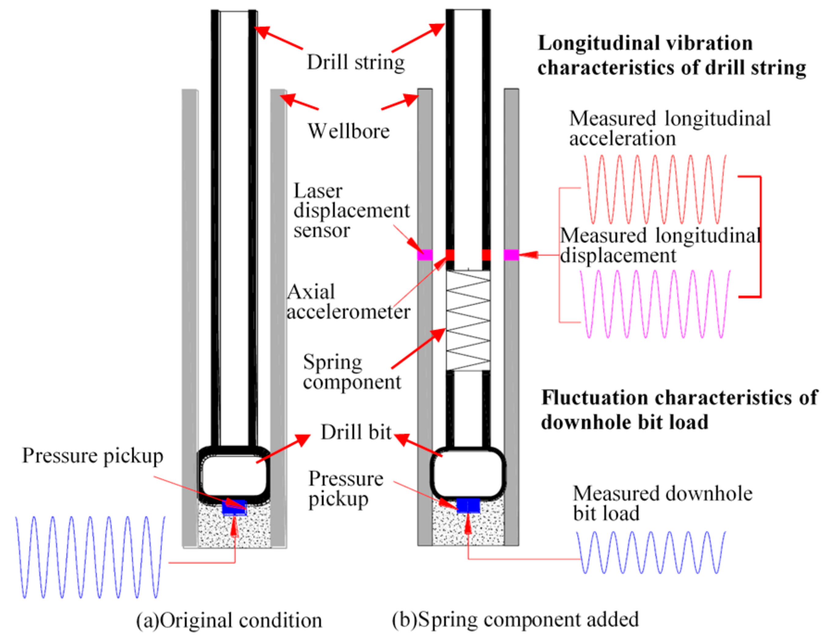
A physical model and its experimental principles were established, as shown in Figure 1, in order to study the characteristics of drill string vibration and downhole bit load and to analyze the energy conversion efficiency of drill string vibration energy to elastic potential energy.
The physical model consists of a wellbore, drill string, drill bit, and spring component. The location of the spring component can be changed according to experimental needs. Figure 1a,b show the original condition with no spring component and the condition with a spring component respectively. When the drill string rotates, the interaction between the drill bit and the downhole rock results in the longitudinal vibration of the drill string.
To measure the variations of drill string vibration and downhole bit load under different conditions (locations of spring component, drilling parameters, et al.), several sensors were designed in the experiment. Laser displacement sensor was installed in the inner wall of the wellbore and was used for the measurement of longitudinal displacement of drill string. The axial accelerometer was installed in the drill string to monitor the acceleration variation during the drilling process. The above two sensors can help to study the characteristics of longitudinal vibration of drill string. The pressure pickup was installed at the bottom of wellbore and was used for the measurement of bit load. It can help to study the fluctuation characteristics of downhole bit load.
2.2. Experimental Device
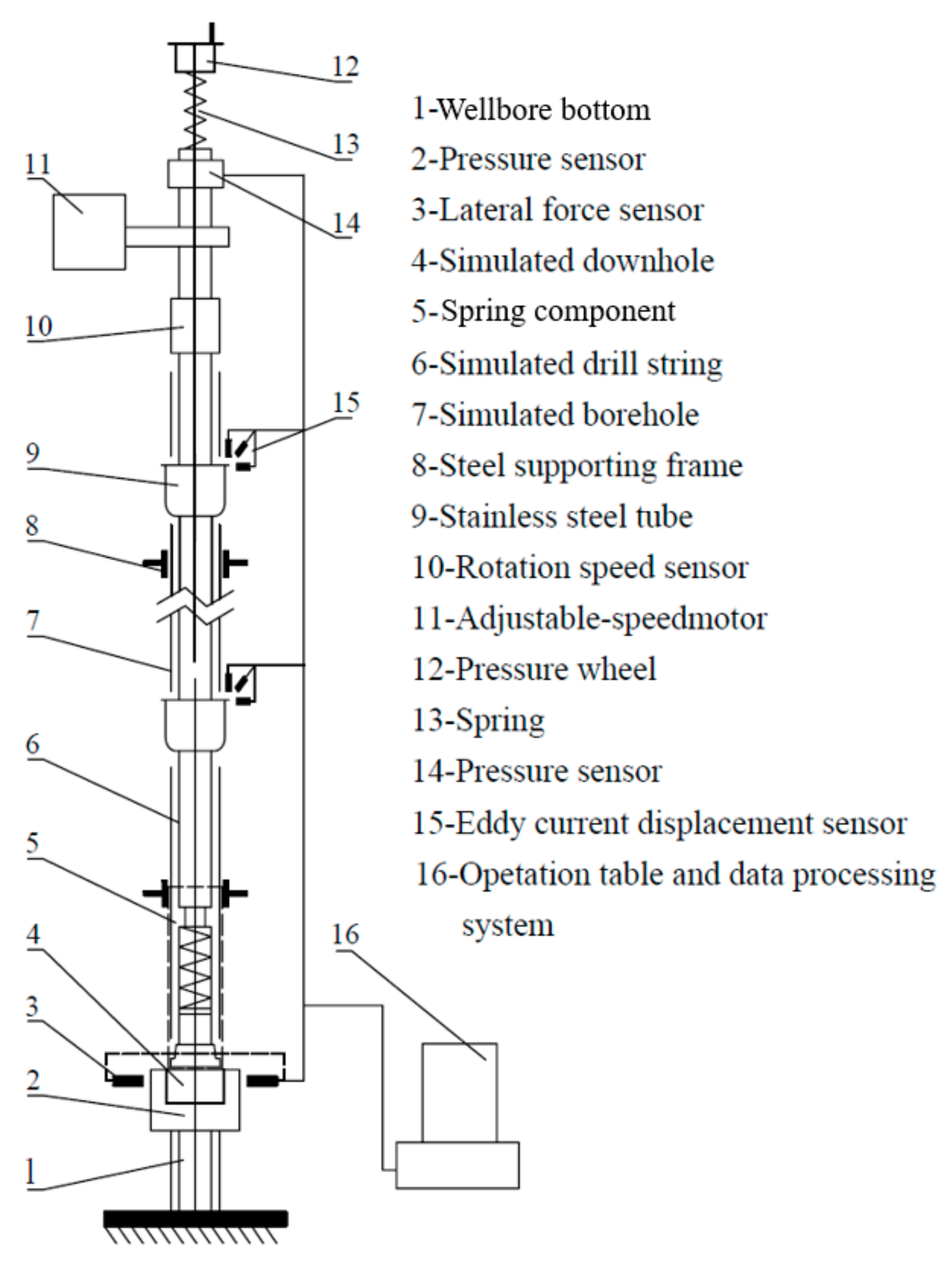
To achieve the purpose as shown in Section 2.1, the drill string simulated in the experiment needs to have the same dynamic characteristics as the actual drill string [21]. In our previous work, the simulated drill string experimental device has been established and designed to have the same dynamic characteristics as the actual ones [8]. The general structure of the experimental device is shown in Figure 2 and a photo is shown in Figure 3.
As is shown in Figure 3, the experimental device consists of two main parts: the vertical part and the horizontal part. In this paper [22], based on the similarity criterion, the experimental parameters were determined, and the vertical part of the device was used to study the vertical drilling process.
The onsite parameters of the wellbore and drill string are as follows:
The inner diameter of the wellbore is 215 mm; bottom hole assembly: φ215 mm Bit + φ178.8 mm Drill Collar × 2 + φ214 mm Stabilizer + φ178.8 mm Drill Collar × 4 + φ178.8 mm Drill Collar × 6 + φ127 mm Drill Pipe.
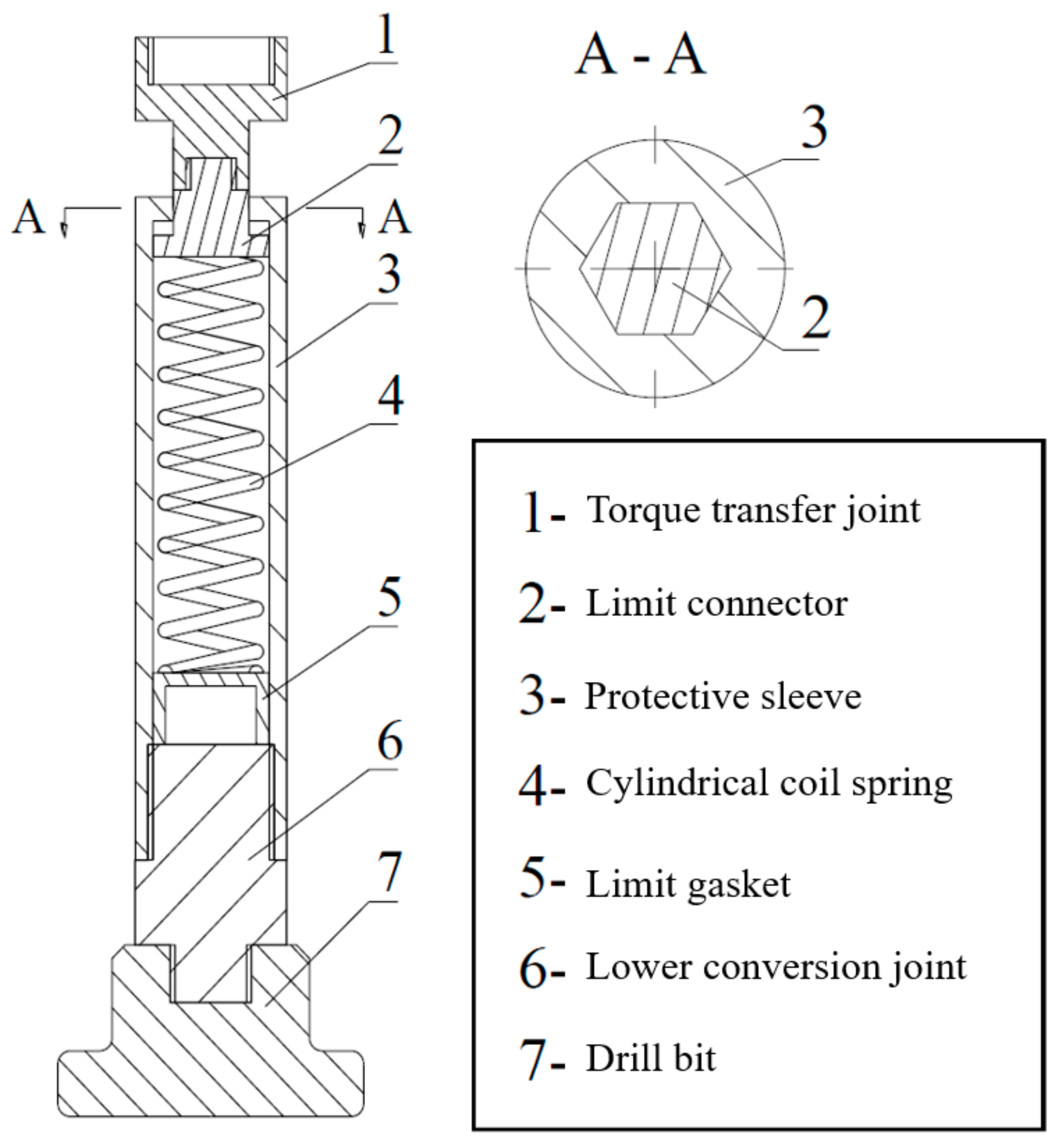
The device was designed according to similarity criterion and was built in 1 to 10 scale penetrates (model to prototype). It was 15 m high in total and had a 13-m high wellbore and drill string. The wellbore was fixed on the steel supporting frame by adjustable nuts, and the drill string was installed in the wellbore by connecting the upper end to the adjustable speed motor and the lower end to the wellbore bottom. The adjustable speed motor can drive the drill string to rotate, and the speed range of the motor can be 0–378 r/min. The material of wellbore was plexiglass, which was transparent, and its inner diameter was 24 mm. The outer diameter of the drill string was 18 mm and its material was ABS plastic whose stress-strain properties are similar to actual drill pipe materials. Specifically, the density of this material is 1.10 g/cm3 and the modulus of elasticity is 2.3 GPa. The diagram of the spring component is shown in Figure 4.
The spring component is a key part of the experimental device. It should have the function of transmitting the bit load, transmitting torque and converting the longitudinal vibration energy of the drill string to the spring elastic potential energy during the simulated drilling process. The length of the spring component was designed to be 0.4 m, and its outer diameter was 18 mm. The torque transfer joint was used to connect the upper drill string and transfer torque through the protective sleeve to the lower drill string. The protective sleeve and the torque transfer joint can reciprocate up and down and the cylindrical coil spring was used to absorb the longitudinal vibration energy of drill string. The lower conversion joint was used to connect the lower drill string.
2.3. Experimental Parameters
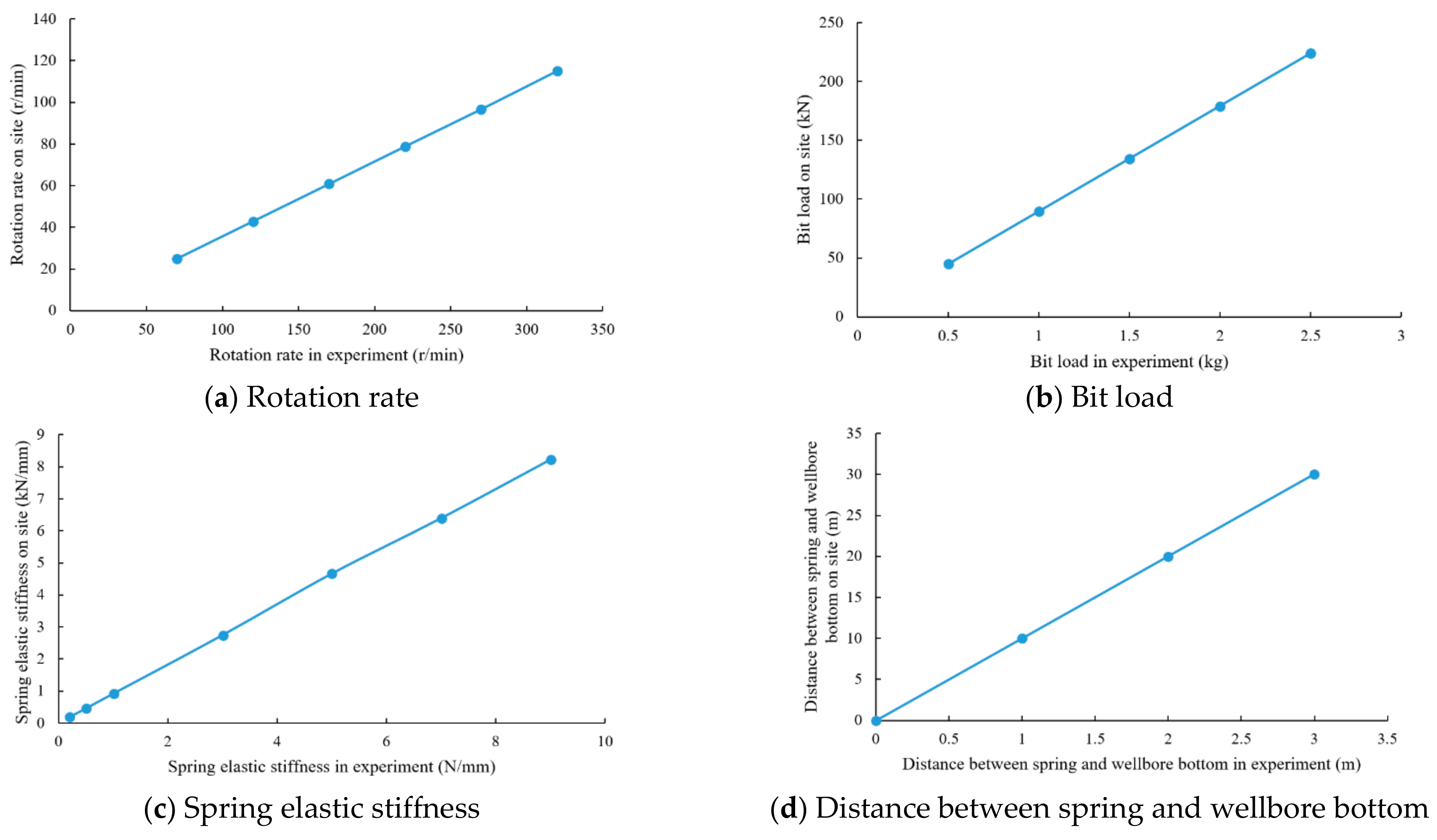
The determination of experimental parameters directly affects the kinematic similarity between the experimental simulation and the real condition. In our previous work, the relationship between experimental parameters and actual onsite parameters was obtained, which is shown in Figure 5.
In the experiment, the parameters can be determined according to the relationship shown in Figure 5.
3. Results and Discussion
3.1. Analysis of Fluctuation Characteristics of Downhole Bit Load
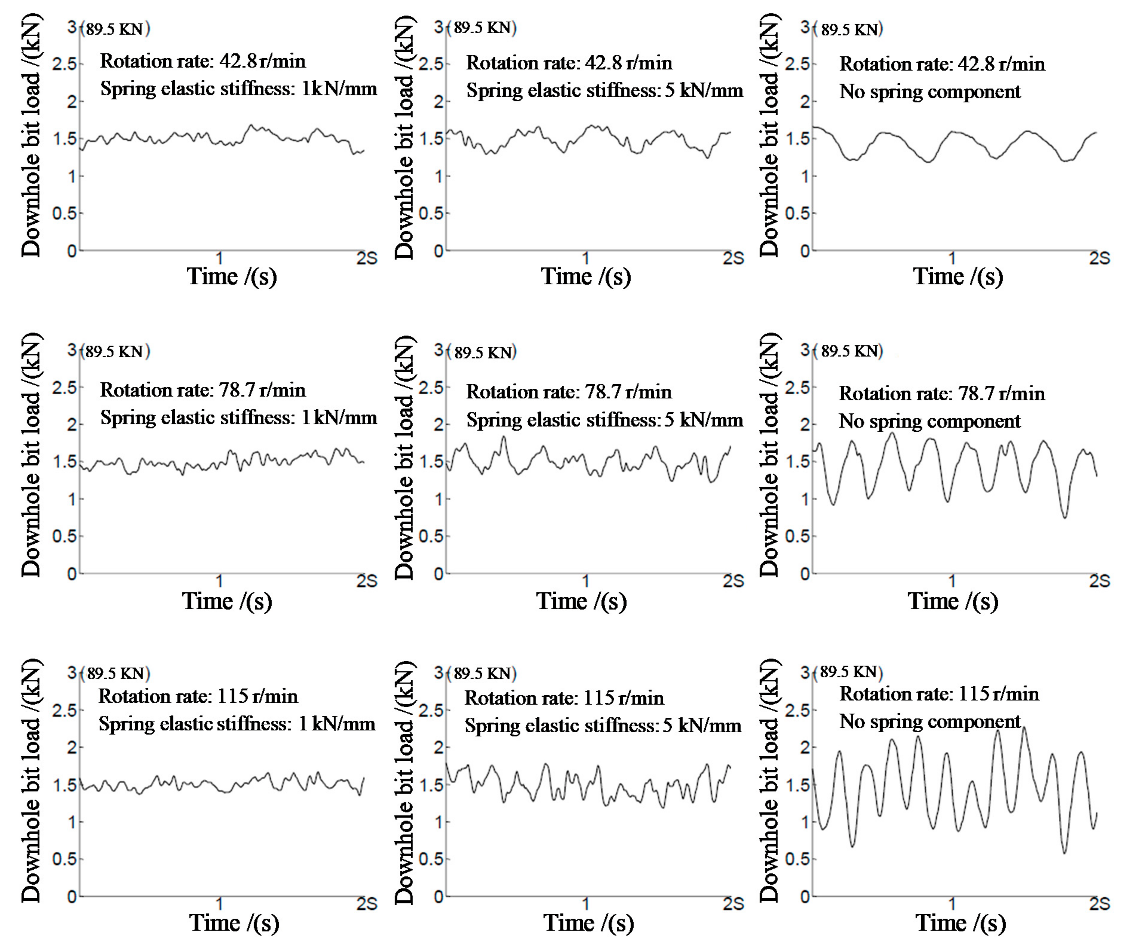
Since the current vibration absorption and hydraulic supercharging tools are usually installed at the bottom hole assembly, so when the spring component is installed near the drill bit, the fluctuation characteristics of the downhole bit load should be studied first. And then, the influence of the position of the spring component on the fluctuation characteristics of the bit load are also be analyzed. Using the experimental device established in Section 2, the variation of the downhole bit load under different conditions of rotation rate, spring elastic stiffness with or with no spring component was tested. The results are shown in Figure 6.
In the experiment, the bit load was set as 134.45 kN and the spring component was installed near the drill bit. According to the analysis, the fluctuation characteristics of the bit load were significantly different in the two conditions of installing and not installing the spring component. When the spring component was not installed, the fluctuation of the bit load was 68–163 kN. In another condition, when the spring component was installed near the drill bit, the fluctuation of bit load reduced to 16–66 kN. Only in the condition of low rotation rate and high spring elastic stiffness (R1N7W3L0), can the fluctuation amplitude of the drill load of two states (with or without spring component) be similar. Under other experimental conditions, the fluctuation amplitude of the bit load was reduced by 10%–90% after the spring component was added. Therefore, the factors such as rotation rate and spring elastic stiffness have a significant influence on the fluctuation characteristics of downhole bit load. It is necessary to further analyse the specific influence law of each parameter.
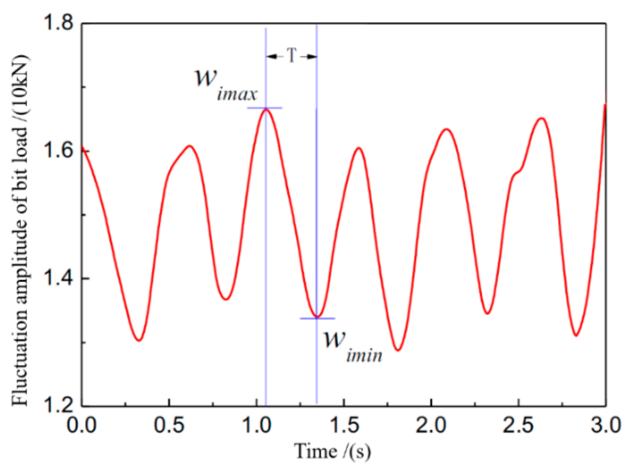
To effectively evaluate the severity of downhole bit load fluctuation in different experimental parameters, the average fluctuation amplitude was defined to measure the severity of the fluctuation. As shown in Figure 7, assuming that there are N cycles of bit load fluctuation in a fixed period of time (3 s), the difference between the maximum and minimum of the bit load in any cycle is defined as the amplitude of bit load fluctuation in that cycle. Then the average bit load fluctuation in a fixed period of time is as follows:
where, is the maximum of bit load in the i cycle, N; is the minimum of bit load in the i cycle, N.
To analyse the decrease of the fluctuation amplitude of bit load after installing the spring component, the ratio of the fluctuation amplitude of bit load under two conditions was defined as the damping coefficient SA:
where, ws is the fluctuation amplitude of bit load when the spring component is installed, N; wns is the fluctuation amplitude of bit load when the spring component is not installed, N.
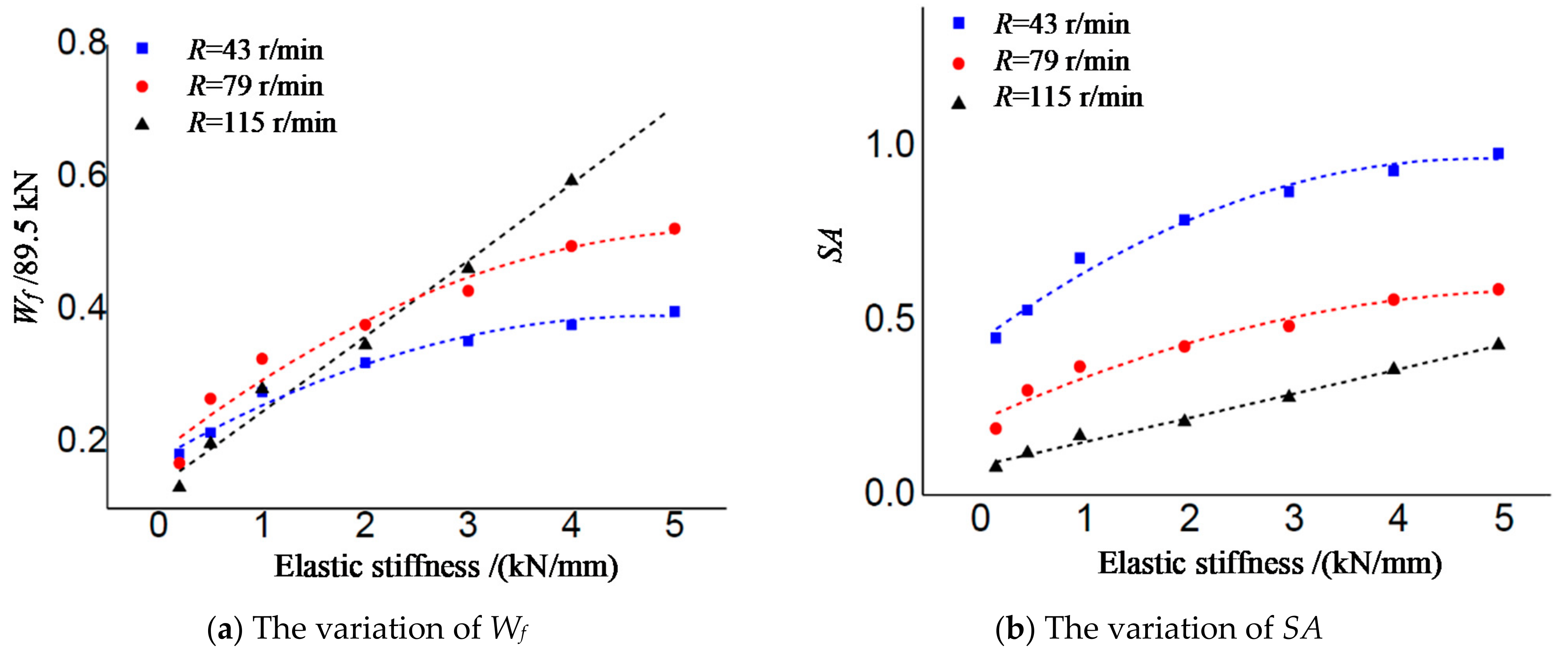
3.1.1. The Influence of Spring Elastic Stiffness
As shown in Figure 8, both Wf and SA rose with the increasing of elastic stiffness of spring under different rotation rates. When the rotation rate was at a low level (43 r/min), the variations of Wf and SA with elastic stiffness were similar. However, when the rotation rate was at a high level (115 r/min), Wf rose dramatically with the increase of elastic stiffness. The small elastic stiffness was conductive to control the downhole bit load fluctuation.
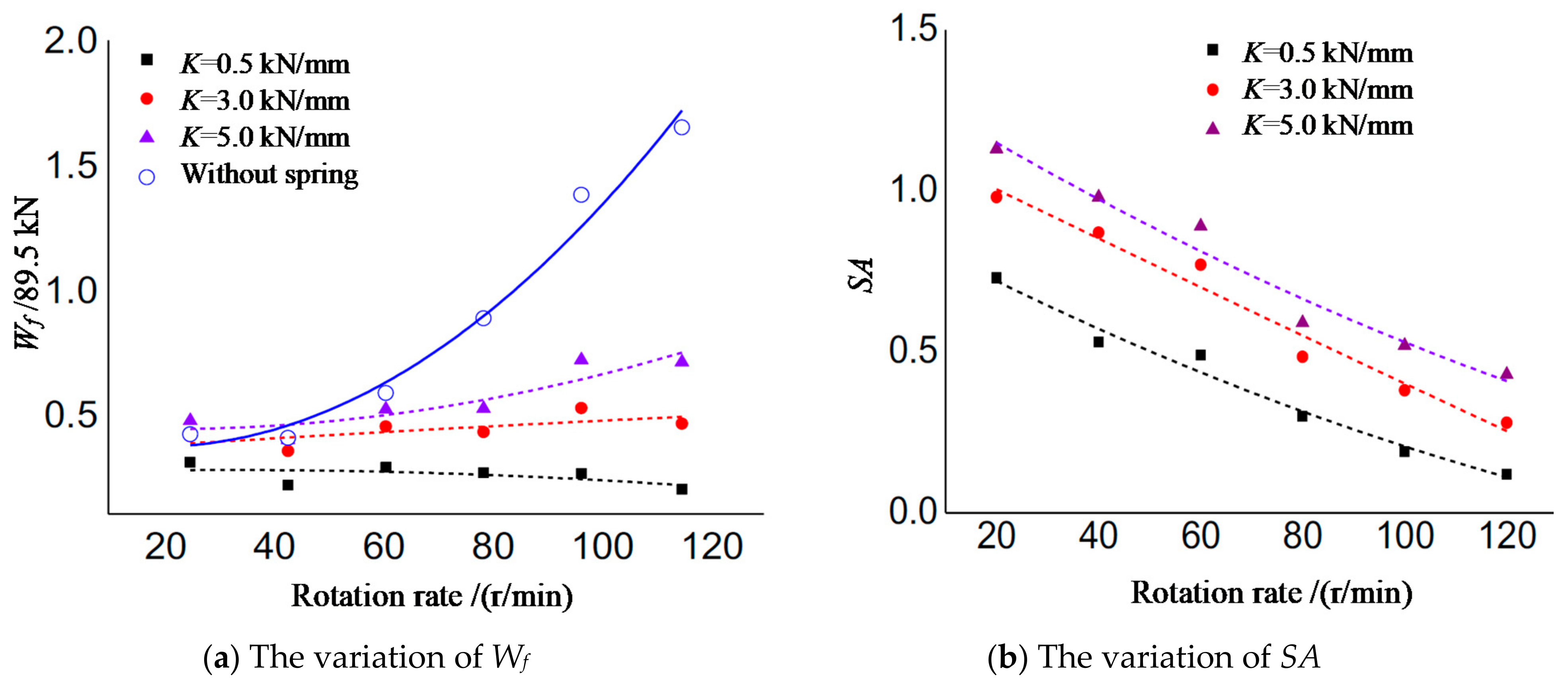
3.1.2. The Influence of Rotation Rate
As shown in Figure 9, Wf rose slightly with the increasing of rotation rate under the condition of great elastic stiffness (N = 3 kN and N = 5 kN). Wf decreased slightly with the increase of rotation rate under the condition of small elastic stiffness (N = 0.5 kN). However, Wf rose dramatically with the increasing of rotation rate when there was no spring component. It can be seen that the spring component can reduce the fluctuation of downhole bit load effectively especially under high rotation rate.
SA decreased linearly with the increasing of rotation rate under different elastic stiffness. More specifically, when the elastic stiffness was great (N = 5 kN/mm), SA was more than 1 under conditions when the rotation rates were less than 42.9 r/min. It indicates that the fluctuation amplitude of bit load became greater when the spring component with high elastic stiffness (N = 5 kN/mm) was installed under the condition of low rotation rate (less than 42.9 r/min).
To summarize, the relatively great rotation rate is beneficial to improve the damping performance of the spring component. Spring with great elastic stiffness is not recommended when the rotation rate is under 42.9 r/min.
3.1.3. The Influence of Downhole Bit Load
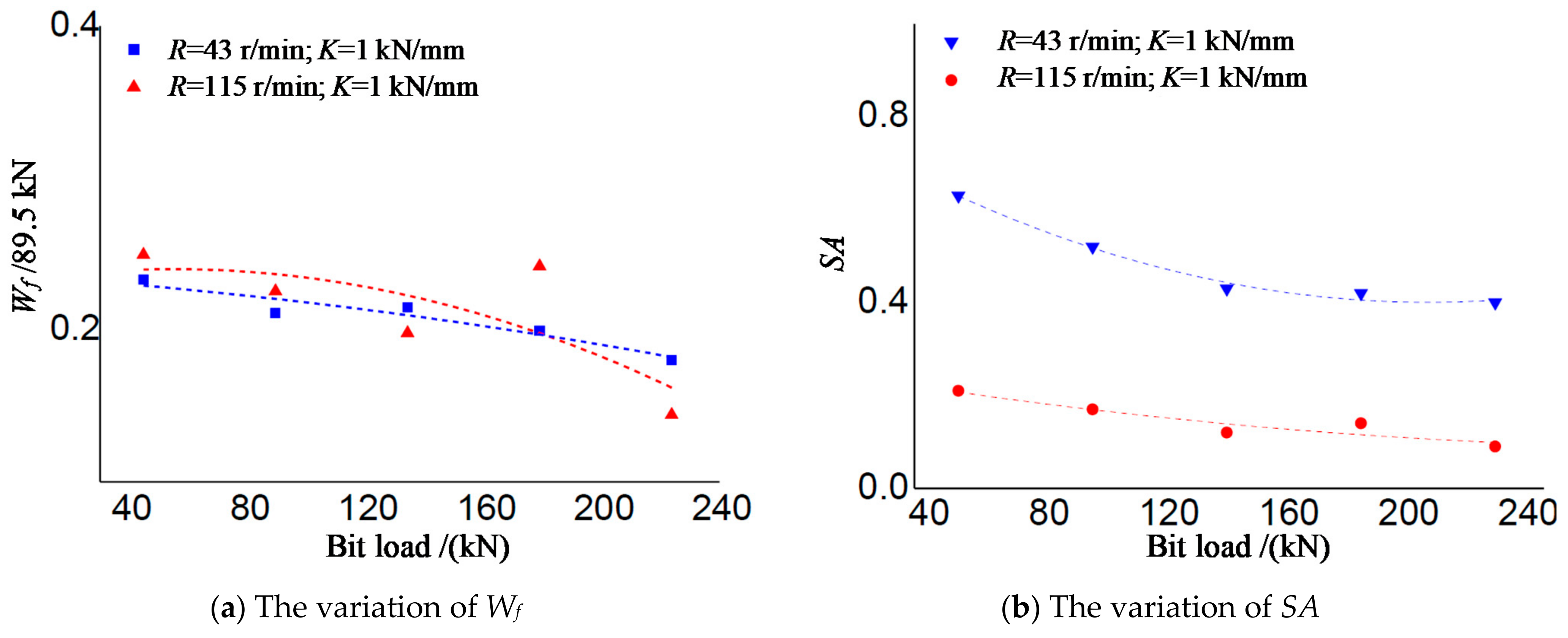
As shown in Figure 10, both Wf and SA gradually decreased gradually with the increasing of bit load, which means that greater bit load is beneficial to reduce the fluctuation of downhole bit load.
3.1.4. The Influence of the Position of Spring Component
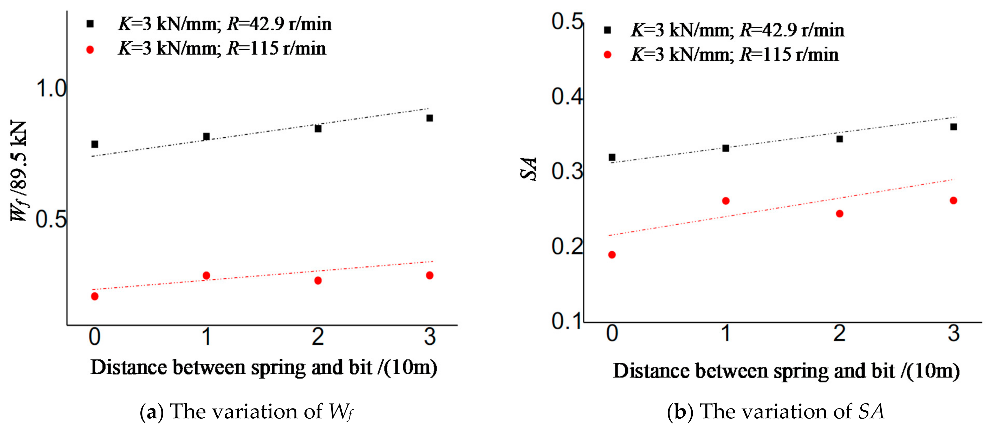
As shown in Figure 11, both Wf and SA gradually rose with the increasing of distance between the spring component and drill bit. It can be seen that installing the spring component near the drill bit is beneficial to control the fluctuation of downhole bit load.
3.2. Analysis of Longitudinal Vibration Characteristics of the Drill String
3.2.1. The Influence of Elastic Stiffness of the Spring Component
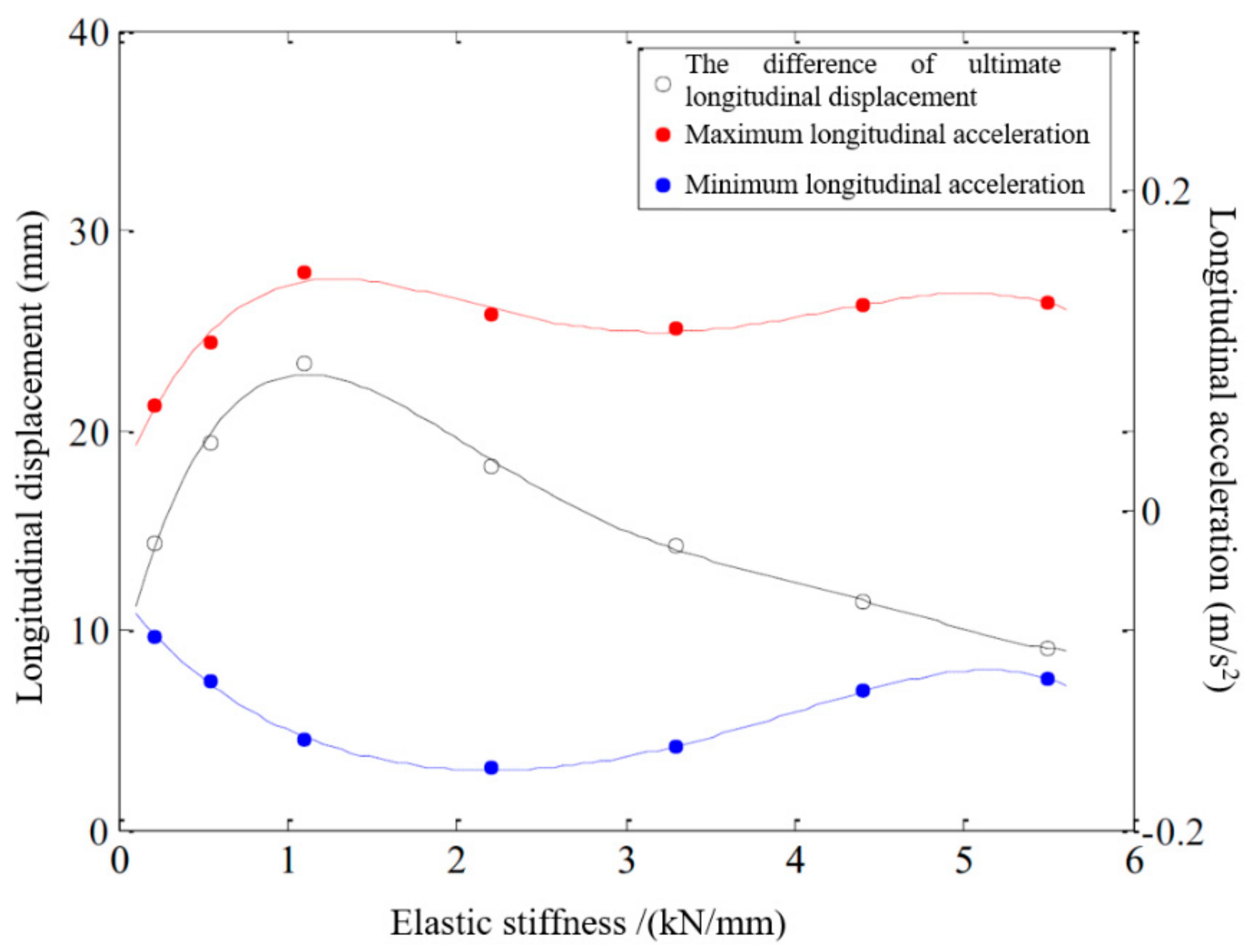
Taking the experimental data as an example, which is under the condition of 134.25 kN bit load, 115 r/min rotation rate and installing spring near the bit. The variation of longitudinal motion amplitude and ultimate acceleration of drill string with elastic stiffness can be obtained, as shown in Figure 12.
According to Figure 12, the longitudinal motion of the drill string had the following characteristics under different elastic stiffness conditions:
The fluctuation amplitude of longitudinal displacement of the drill string increasing first and then decreased with the increase of elastic stiffness. When the elastic stiffness of spring was small (0.2 kN/mm), the spring component absorbed most of the energy of the longitudinal
Vibration of the drill string, and the longitudinal vibration amplitude of drill string was small, about 14 mm. Under the condition of large elastic stiffness (5 kN/mm), the downward movement resistance of the upper drill string was large, which limited the longitudinal movement range of the drill string and kept the longitudinal movement amplitude of the drill string at a low level, about 10 mm. The longitudinal displacement of drill string varied between 10–23 mm under different elastic stiffness conditions. When the elastic stiffness was 1 kN/mm, the longitudinal displacement of the drill string was the largest, about 23 mm.
The absolute acceleration of drill string moving upward and downward increased firstly and then decreased with the increasing of elastic stiffness. When the elastic stiffness was 1 kN/mm, the longitudinal acceleration of the drill string was the largest, the downward longitudinal acceleration of the drill string was about 0.15 g m/s2, and the upward longitudinal acceleration of the drill string was about 0.14 g m/s2.
Under different elastic stiffness conditions, the longitudinal motion of the drill string was quite different. At high rotation rate (115 r/min), when the elastic stiffness was 1 kN/mm, the longitudinal displacement amplitude and acceleration of drill string showed extreme values.
3.2.2. The Influence of Rotation Rate
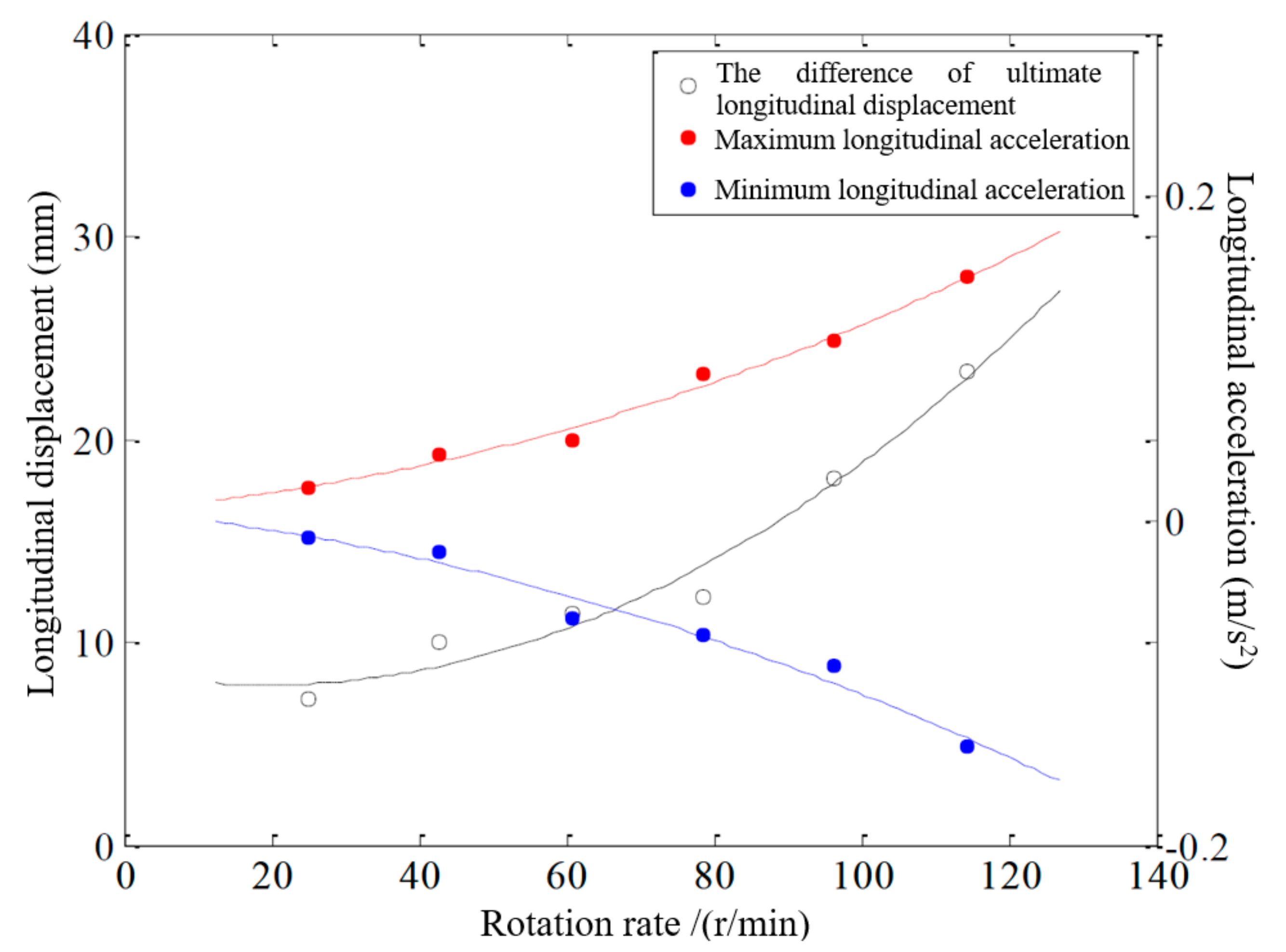
Taking the experimental data which is under the condition of 134.25 kN bit load, 1 kN/mm elastic stiffness and installing spring near the bit as an example. The variation of longitudinal motion amplitude and ultimate acceleration of drill string with rotation rates are shown in Figure 13.
According to Figure 13, the longitudinal motion of the drill string had the following characteristics under different rotation rates conditions:
The longitudinal motion amplitude of drill string rose with the increasing of rotation rate. It was about 10 mm at low rotation rate (42.9 r/min) and reached 23 mm at high rotation rate (115 r/min).
The absolute acceleration of drill string moving upward and downward increased with the increasing of rotation rate.
The longitudinal vibration frequency of drill string was only related to the rotation rate, about 2.77 times of the actual rotation rate, which was consistent with the rotation rate in the simulation experiment.
Rotation rate had a significant effect on the longitudinal movement of the drill string. The higher the rotation rate, the more severe the longitudinal vibration of the drill string above the spring component was.
3.2.3. The Influence of Bit Load
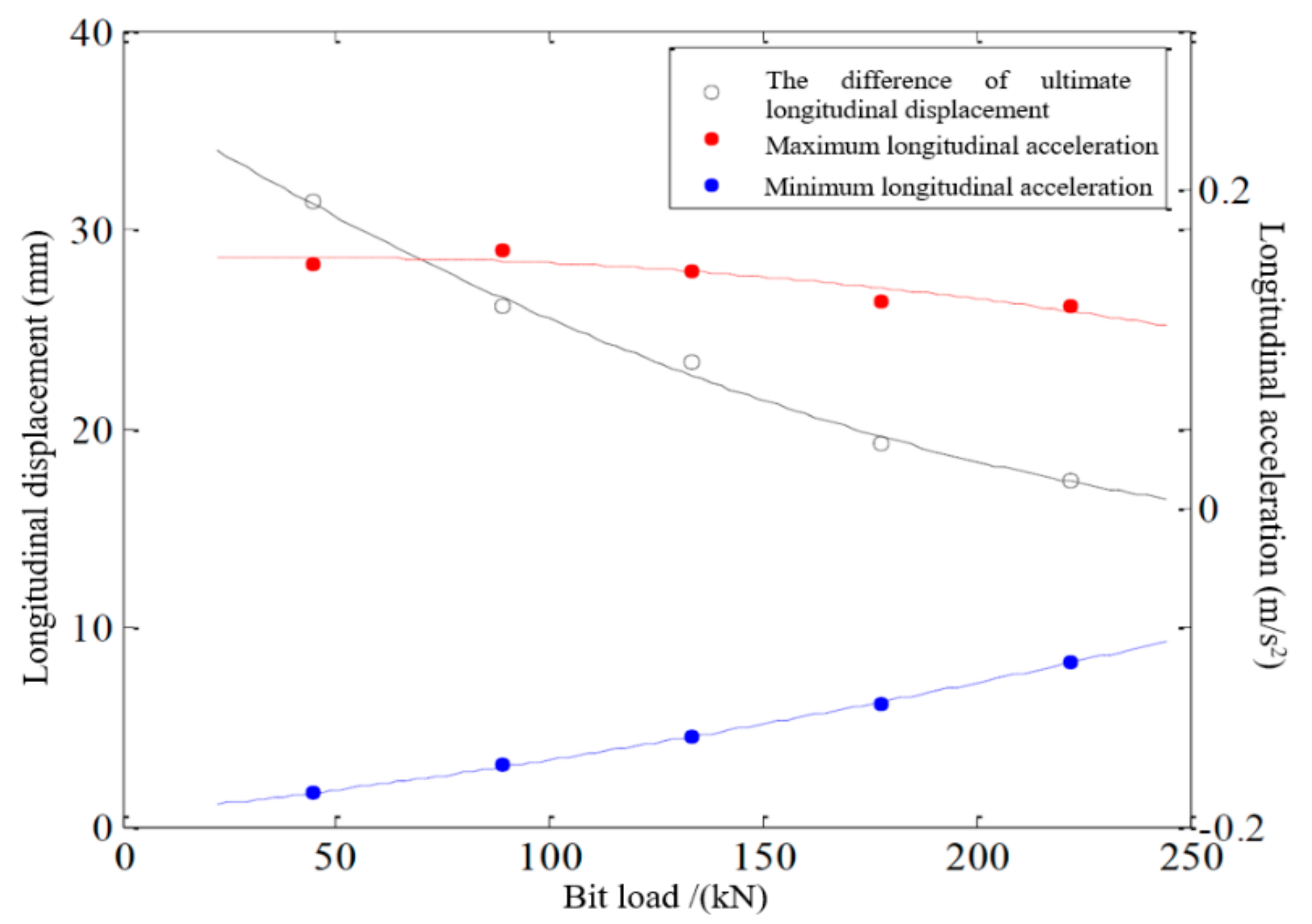
Taking the experimental data, which is under the condition of 1 kN/mm elastic stiffness, 115 r/min rotation rate and installing spring near the bit as an example. The variation of longitudinal motion amplitude and ultimate acceleration of drill string with bit load are shown in Figure 14.
According to Figure 14, the longitudinal motion of the drill string had the following characteristics under different bit loads conditions:
The longitudinal motion amplitude of drill string decreased with the increasing of bit load. It was about 31 mm at low bit load (44.74 kN) and decreased to 17 mm at high bit load (223.75 kN).
The absolute acceleration of the drill string decreased with the increasing of bit load.
The influence of bit load on the longitudinal acceleration of the drill string was relatively small, but it had a large influence on the longitudinal displacement amplitude. In general, increasing the bit load will inhibit the severity of the longitudinal vibration of the drill string above the spring component.
3.2.4. The Influence of the Spring Component Position
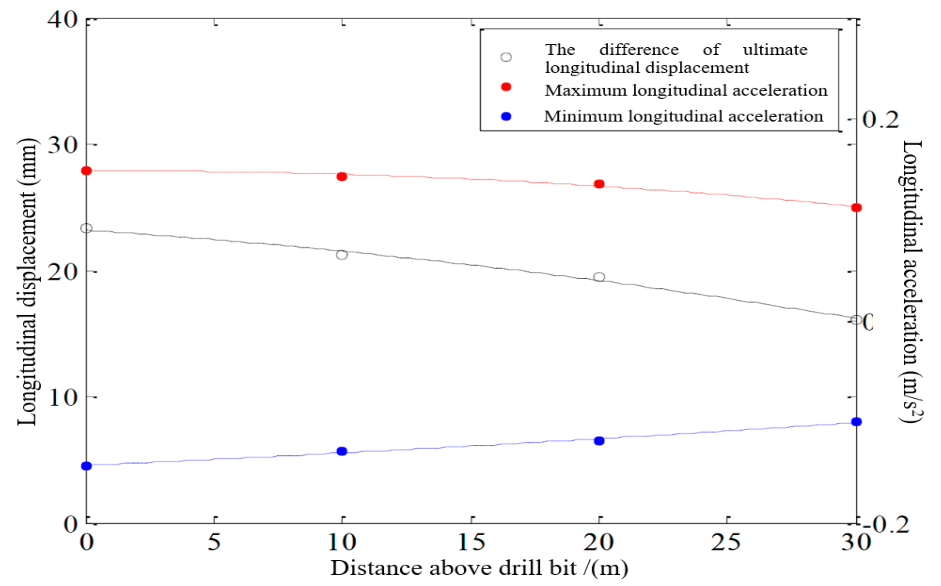
Taking the experimental data, which is under the condition of 134.25 kN bit load, 115 r/min rotation rate and 1 kN/mm elastic stiffness, as an example. The variation of longitudinal motion amplitude and ultimate acceleration of the drill string with spring locations can be obtained, as shown in Figure 15.
According to Figure 15, the longitudinal motion of drill string had the following characteristics under different spring location conditions:
The longitudinal motion amplitude of drill string decreased gradually with the upward of spring component. It was about 23 mm when the spring component was installed near the bit and decreased to 16 mm when the spring component was installed 30 m above the bit.
The absolute acceleration of drill string moving upward and downward gradually decreased with the upward of spring component.
The influence of spring location on the longitudinal acceleration of the drill string above the spring was relatively small.
3.3. Analysis Method of Conversion Efficiency of Drill String Vibration Energy to Elastic Potential Energy
3.3.1. Equivalent Evaluation Method
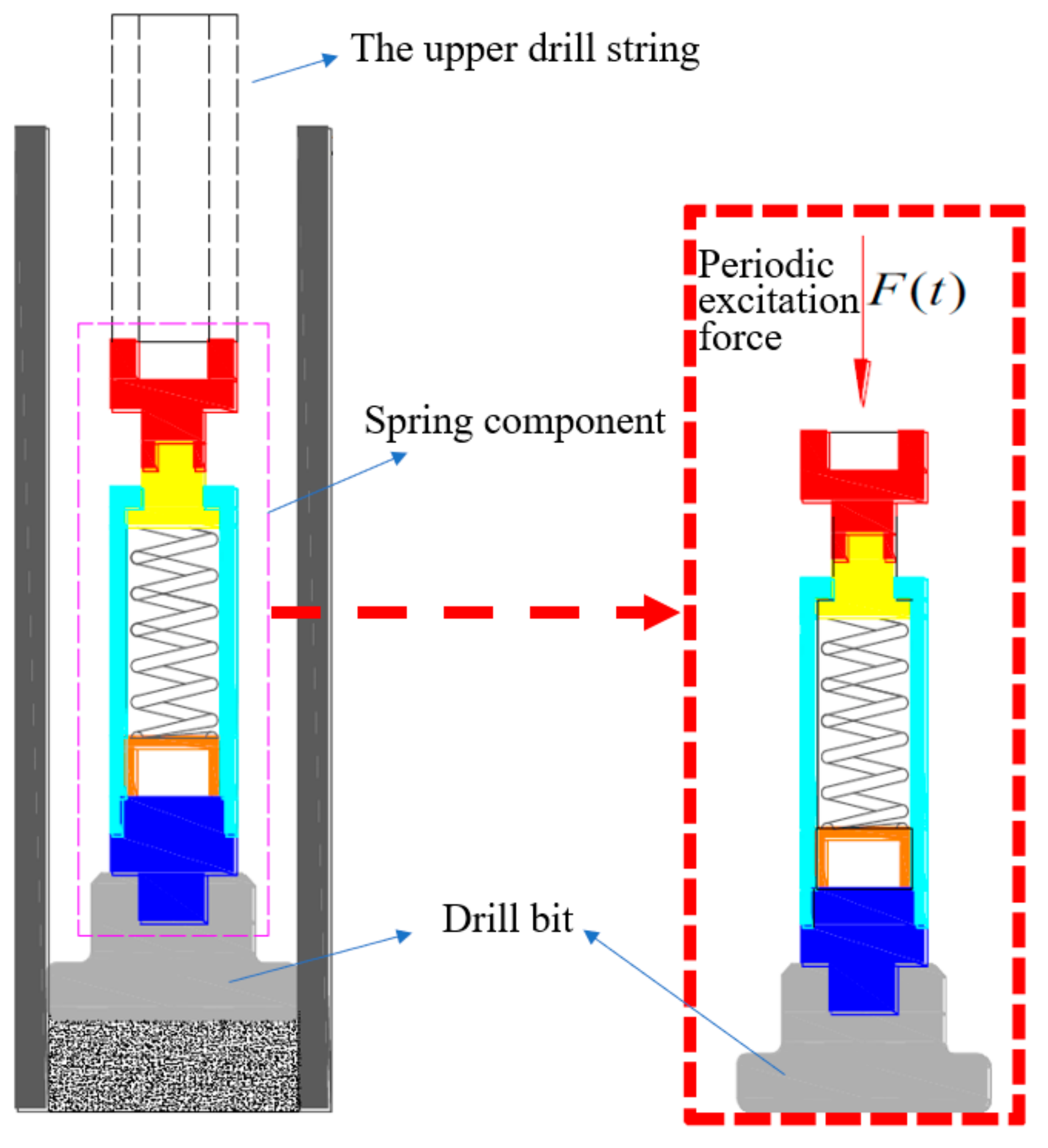
Through the experiment, the influence of spring elastic stiffness, installation position and other drilling parameters on the longitudinal movement characteristics of the drill string can be intuitively recognized, but it is difficult to quantitatively evaluate the effect of the longitudinal vibration of the upper drill string on the spring component, i.e., the energy conversion efficiency. Therefore, this paper simplified the spring component and its lower drill string and drill bit into a single-degree-of-freedom elastic system. The effect of the upper drill string vibration on the spring component was equivalent to the periodic excitation force applied to the spring, as shown in Figure 16. By calculating the magnitude of the equivalent excitation force and its work power to the spring component, the purpose of quantitatively evaluating the effect of the upper drill string on the spring component during the longitudinal vibration was achieved.
The simplified elastic system satisfies the dynamic balance equation:
where, F(t) represents the equivalent periodic excitation force, N; M a represents the mass of the drill string below the neutral point, but does not include the mass of the drill string and drill bit below the spring component, kg; C represents the damping value of spring, dimensionless; K represents the elastic stiffness of the spring, N/m; represents the measured longitudinal acceleration of the upper drill string of spring component, m/s2; represents the longitudinal movement speed of the upper drill string of the spring component (calculated by the differential method based on the measured longitudinal displacement data of the drill string), m/s; represents the measured longitudinal displacement of the upper drill string of the spring component, m.
Each set of experimental data had the same sampling frequency of 1000 Hz using linear interpolation. Equation (3) can be used to calculate the equivalent excitation force under different experimental parameters. Combined with the measured longitudinal displacement data of the drill string, the work power of the equivalent excitation force to the spring component can be calculated, thereby quantitatively evaluating the effect of the longitudinal vibration of the upper drill string on the spring component.
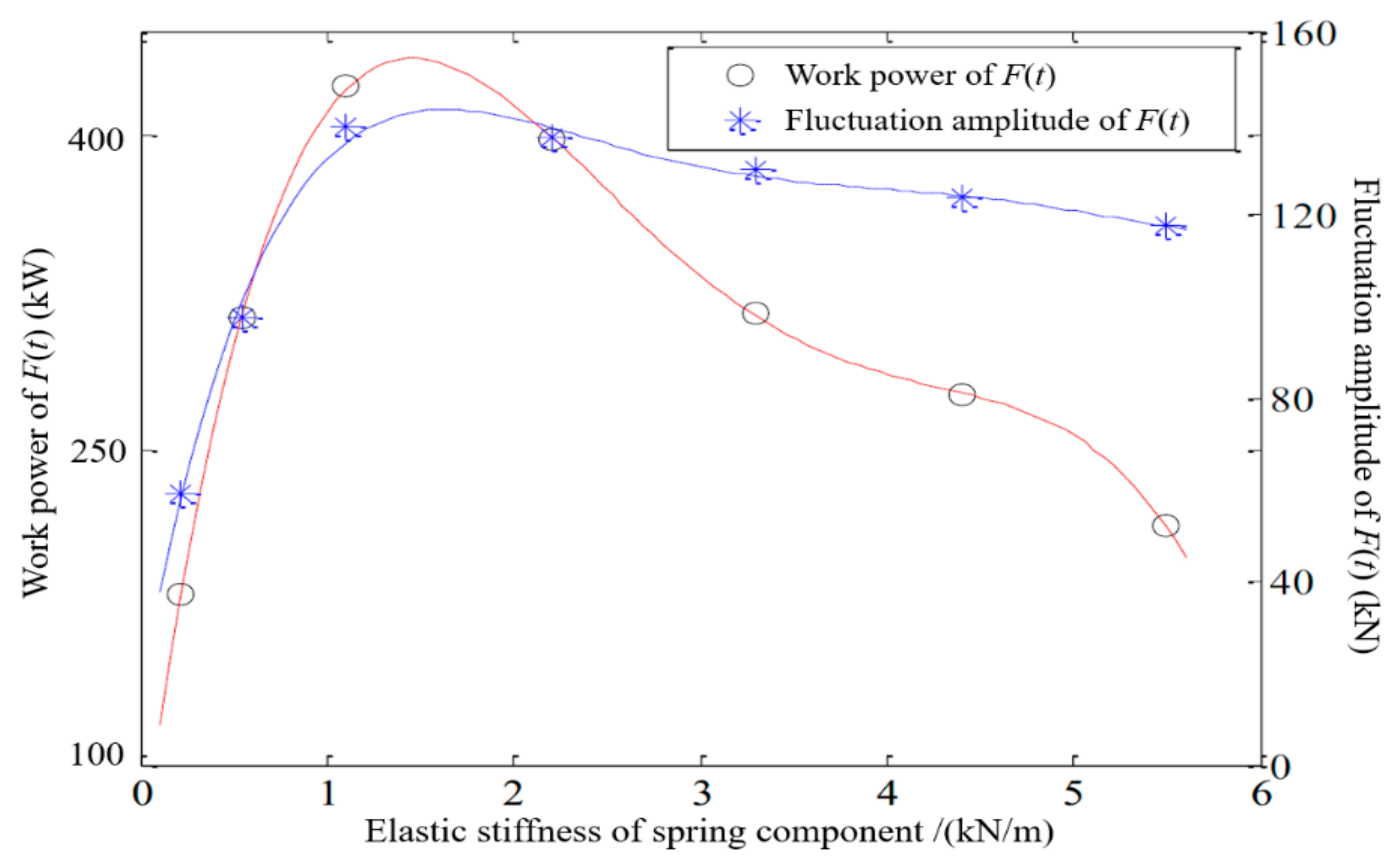
3.3.2. The Influence of Elastic Stiffness on the Energy Conversion Efficiency
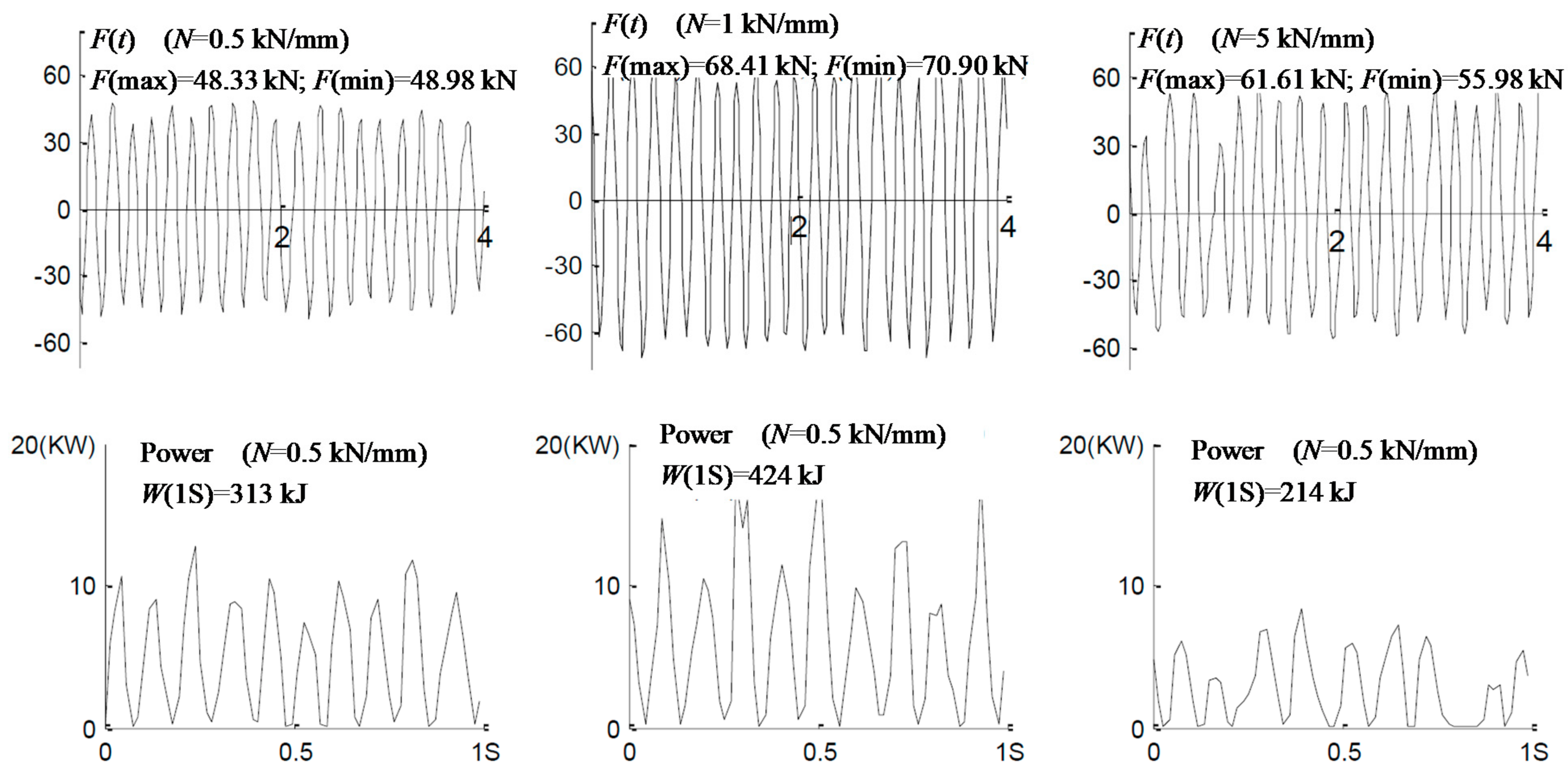
Taking the experimental data in Section 3.2.1 as an example, the time-domain diagrams of equivalent excitation force and its work power to the spring component were calculated by the method described in Section 3.3.1, as shown in Figure 17.
According to Figure 17 and Figure 18, the effect of the longitudinal vibration of the drill string on the spring component had the following characteristics under different elastic stiffness conditions:
The fluctuation amplitude of F(t) increased sharply at fist and then decreased slowly with the increasing of elastic stiffness. When the elastic stiffness was 1 kN/mm, the F(t) varied from −68 kN to 70 kN. At this time, the amplitude of F(t) was the largest, about 138 kN.
The work power of F(t) to the spring component increased sharply at fist and then decreased with the increasing of elastic stiffness. When the elastic stiffness was between 1 kN/mm and 2 kN/mm, the equivalent excitation force had the largest working power for the spring component, above 400 kW.
To achieve the purpose of best energy conversion effect, the elastic stiffness should range from 1 kN/mm to 2 kN/mm. Within this range of elastic stiffness, the work power of the longitudinal vibration of the upper drill string to the spring component was the greatest.
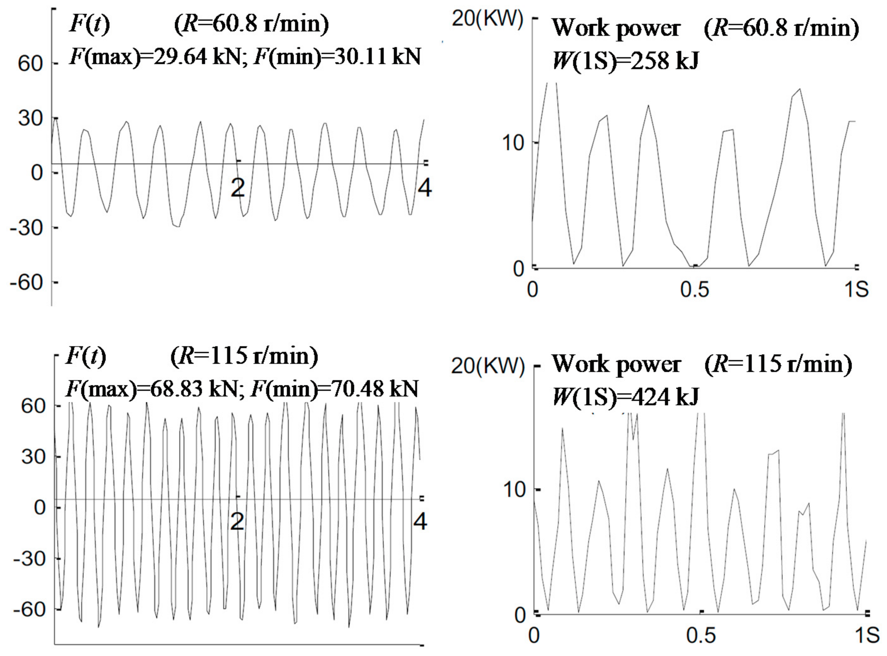
3.3.3. The Influence of Rotation Rate on the Energy Conversion Efficiency
Taking the experimental data in Section 3.2.2 as an example, the time-domain diagrams of equivalent excitation force and its work power to the spring component were calculated by the method described in Section 3.2.1, as shown in Figure 19.
According to Figure 19 and Figure 20, the effect of the longitudinal vibration of the drill string on the spring component had the following characteristics under different rotation rate conditions:
The fluctuation amplitude of F(t) increased linearly with the increasing of rotation rate. Under low rotation rate (60.8 r/min), F(t) varied between −30 kN and 20 kN, and the fluctuation amplitude range was about 50 kN. Under high rotation rate (115 r/min), F(t) varied between—68 kN and 70 kN, and the fluctuation amplitude was about 138 kN.
The work power of F(t) to the spring component increased linearly with the increasing of rotation rate. It increased from 254 kW at a low rotation rate (60.8/min) to 424 kW at a high rotation rate (115 r/min).
The greater the rotation rate, the more work power of the longitudinal vibration of the upper drill string to the spring component was.
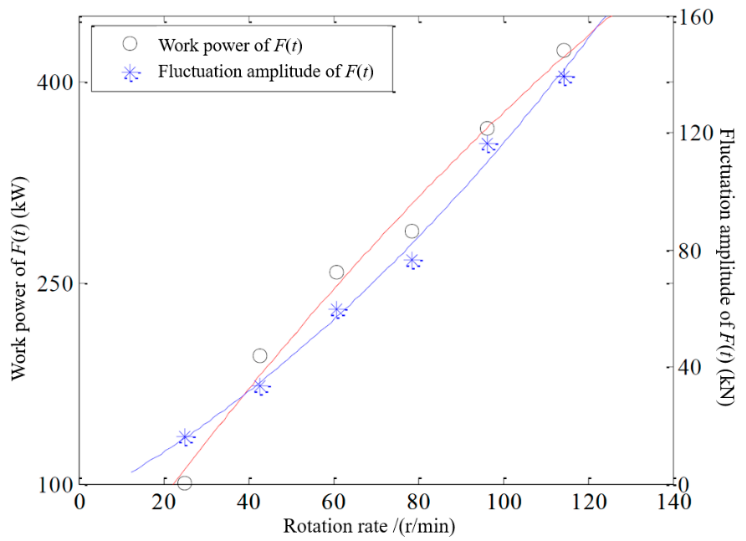
3.3.4. The Influence of Bit Load on the Energy Conversion Efficiency
Taking the experimental data in Section 3.2.3 as an example, the time-domain diagrams of equivalent excitation force and its work power to the spring component were calculated by the method described in Section 3.3.1, as shown in Figure 21.
According to Figure 21 and Figure 22, the effect of the longitudinal vibration of the drill string on the spring component had the following characteristics under different bit load conditions:
The fluctuation amplitude of F(t) gradually rose with the increasing of bit load and tended to be stable.
The work power of F(t) to the spring component increased slowly fist and then decreased with the increasing of bit load. It reached the greatest value at about 424 kW when the bit load was 134.25 kN.
Increasing the bit load was not conducive to the energy conversion of the drill string vibration. The bit load lower than 134.5 kN can ensure the better energy conversion effect of the drill string vibration.
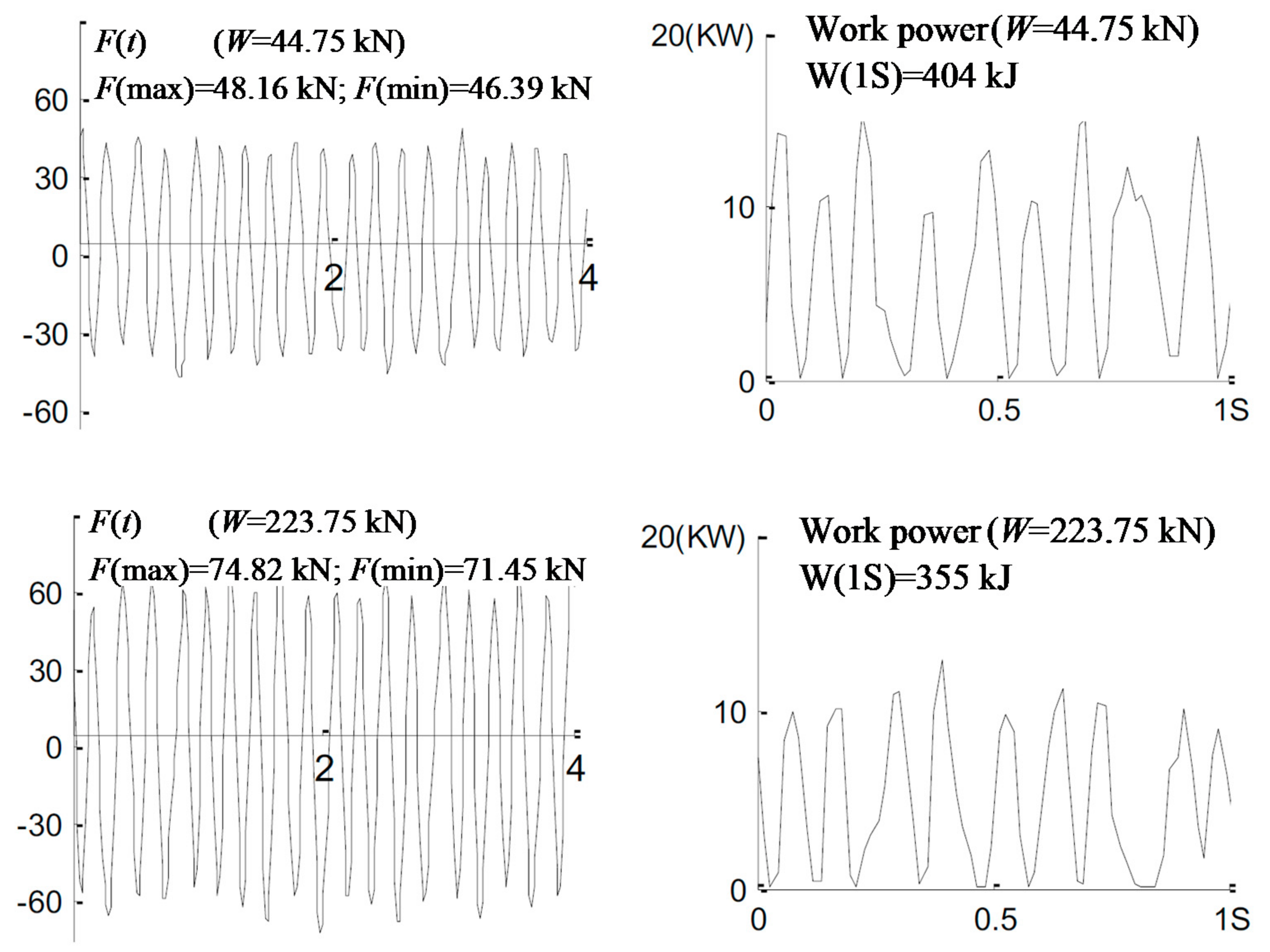
3.3.5. The Influence of Spring Position on the Energy Conversion Efficiency
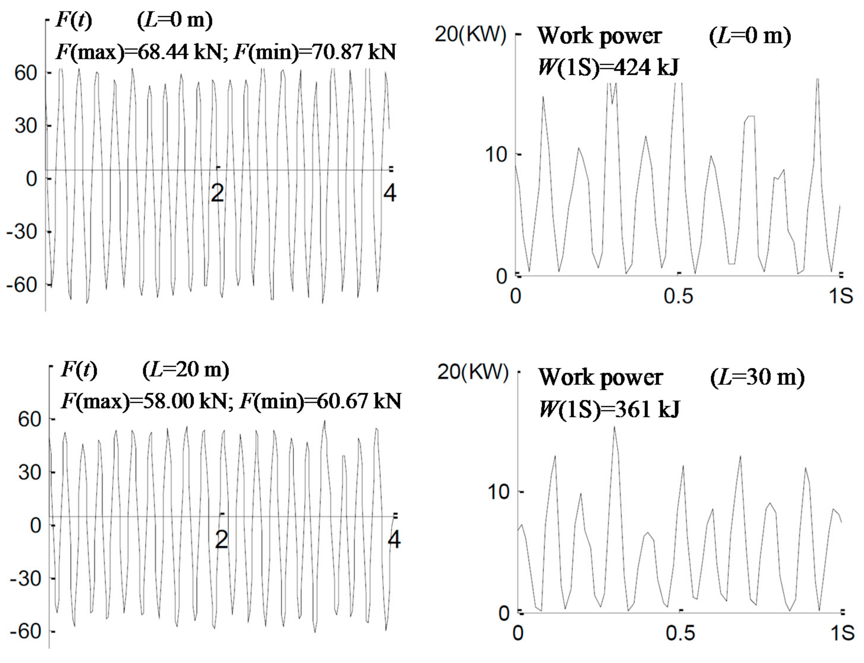
Taking the experimental data in Section 3.2.4 as an example, the time-domain diagrams of equivalent excitation force and its work power to the spring component were calculated by the method described in Section 3.3.1, as shown in Figure 23.
According to Figure 23 and Figure 24, the effect of the longitudinal vibration of the drill string on the spring component had the following characteristics under different bit load conditions:
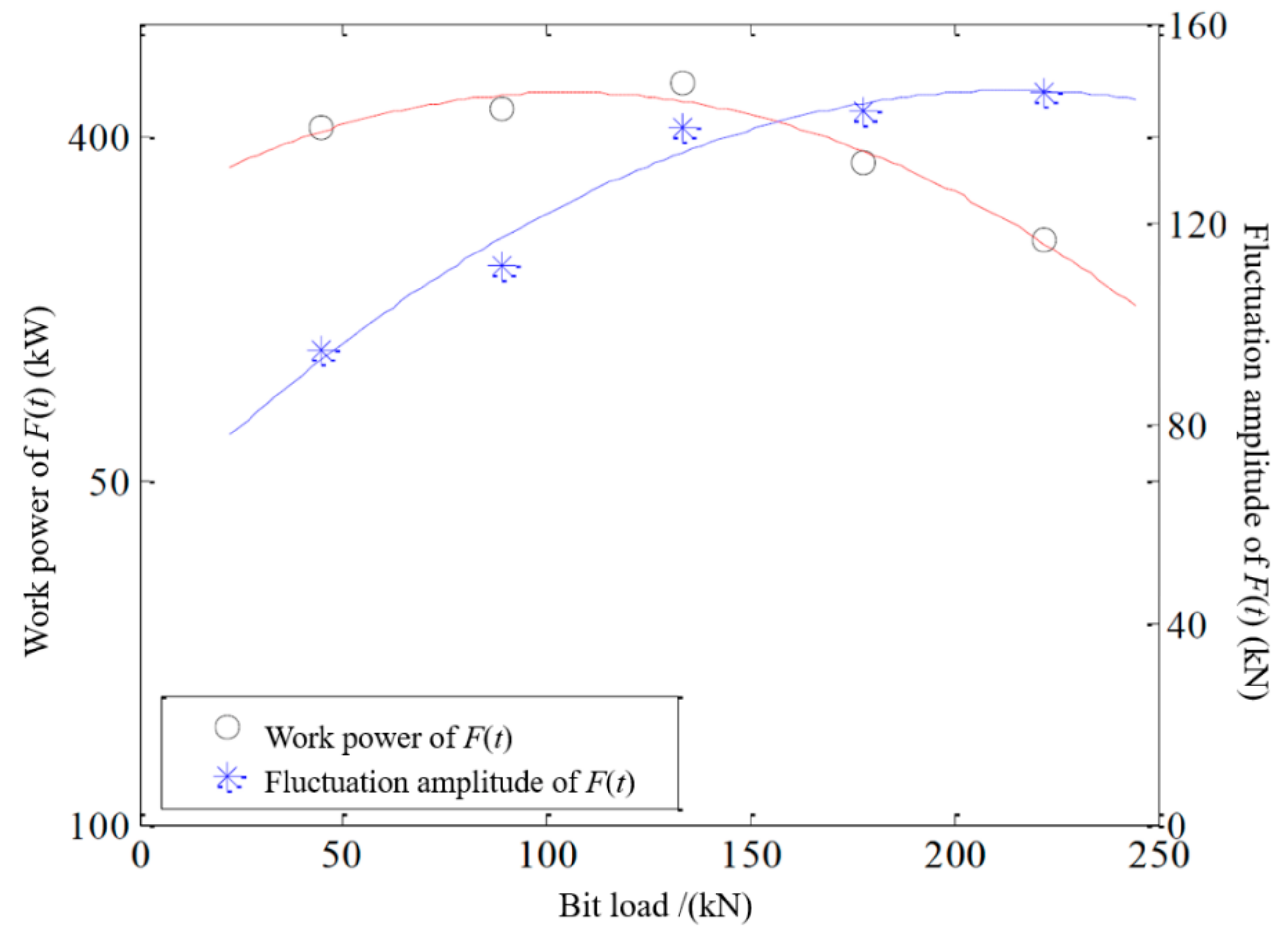
The fluctuation amplitude of F(t) decreased linearly with the increasing of distance between spring and bit.
The work power of F(t) to the spring component decreased linearly with the increasing of distance between spring and bit. It started from 424 kW of the distance of 0 and decreased to 361 kW of the distance of 30 m.
The best way to convert the vibration energy of the drill string is to adopt the method of installing the spring component near the drill bit
4. Conclusions
- The characteristics of fluctuation of downhole bit load and longitudinal vibration of drill string under different drilling parameters, spring performances, and installation positions were studied by experimental research.
- The experimental analysis shows that the fluctuation of the downhole bit load was reduced by 10%–90% after the spring component was installed in the bottom hole assembly. The rotation rate and the spring elastic stiffness had a significant and positive influence on the fluctuation amplitude of the downhole bit load, while the impact of the bit load and the spring position on the fluctuation amplitude of downhole bit load was relatively small.
- The relationship between drilling parameters, spring elastic stiffness and its installation positions, and the longitudinal motion of drill string was analysed. The research shows that the longitudinal movement amplitude and acceleration of the drill string increased at first and then decreased with the increasing of elastic stiffness. The longitudinal vibration amplitude and acceleration of the drill string reached their maximum value when the elastic stiffness was 1 kN/mm; The closer the spring position to the drill bit or the higher the rotation rate, the more severe the longitudinal vibration of the drill string above the spring component was; Increasing the bit load suppressed the severity of the longitudinal vibration of the drill string above the spring component.
- The evaluation method of energy conversion efficiency from drill string vibration to spring potential energy was established. The research shows that: the available mechanical energy range of the drill string longitudinal vibration during drilling is about 200–420 kW. The influence of drilling parameters, elastic stiffness and its installation position on the vibration energy conversion effect of the drill string was analyzed. The work power of the drill string vibration to the spring component increased sharply at first and then decreased with the increasing of elastic stiffness. When the elastic stiffness was between 1 kN/mm and 2 kN/mm, the energy conversion efficiency from drill string vibration to spring potential energy reached the optimum value. Increasing the rotation rate, keeping the bit load below 134.5 kN and installing the spring component near the drill bit all contribute to the improvement of the energy conversion efficiency of drill string vibration.
Author Contributions
Y.X. did the methodology, writing review and editing; H.Z. did the experiment and analysis, writing review and editing; Z.G. did the supervision, resources and review. All authors have read and agreed to the published version of the manuscript.
Funding
National Natural Science Foundation of China (No. 52074326).
Institutional Review Board Statement
Not applicable.
Informed Consent Statement
Not applicable.
Data Availability Statement
Not applicable.
Acknowledgments
The authors would like to acknowledge the academic and technical supports of China University of Petroleum (East China). This paper is supported by the National Natural Science Foundation of China (No. 52074326).
Conflicts of Interest
The authors declare no conflict of interest.
References
- Ghasemloonia, A.; Rideout, D.G.; Butt, S.D. A review of drillstring vibration modeling and suppression methods. J. Pet. Sci. Eng. 2015, 131, 150–164. [Google Scholar] [CrossRef]
- Dong, G.; Chen, P. A Review of the Evaluation, Control, and Application Technologies for Drill String Vibrations and Shocks in Oil and Gas Well. Shock. Vib. 2016, 2016, 1–34. [Google Scholar] [CrossRef] [Green Version]
- Liu, Y.; Guan, Z.; Zhang, H. Research status and prospect of ROP-enhancing technology based on drill string vibration. China Offshore Oil Gas 2017, 4, 131–137. [Google Scholar]
- Chen, P.; Gao, D.; Wang, Z.; Huang, W. Study on aggressively working casing string in extended-reach well. J. Pet. Sci. Eng. 2017, 157, 604–616. [Google Scholar] [CrossRef]
- Zeng, Q.; Yao, J.; Shao, J. An extended finite element solution for hydraulic fracturing with thermo-hydro-elastic–plastic coupling. Comput. Methods Appl. Mech. Eng. 2020, 364, 112967. [Google Scholar] [CrossRef]
- Zhao, D.Y.; Yang, H.B.; Yang, Y.B. Analysis and research of vertical vibration law of deep well drill tool. Drill. Prod. Technol. 2002, 25, 14–16. [Google Scholar]
- Al Dushaishi, M.F. Investigation of Drillstring Vibration Reduction Tools. Master’s Thesis, Missouri University of Science and Technology, Rolla, MO, USA, 2012. [Google Scholar]
- Zhang, H.; Guan, Z.; Liu, Y.; Liang, D.; Xu, Y. A novel tool to improve the rate of penetration by transferring drilling string vibration energy to hydraulic energy. J. Pet. Sci. Eng. 2016, 146, 318–325. [Google Scholar] [CrossRef]
- Guan, Z.; Liu, Y.; Wei, W.; Guan, B.; Shi, Y.; Zhang, H. Method and System for Improving Drilling Speed by Using Drill Speed Vibration. U.S. Patent No. 9,540,881, 1 October 2017. [Google Scholar]
- Chen, P.; Miska, S.Z.; Ren, R.; Yu, M.; Ozbayoglu, E.; Takach, N. Poroelastic modeling of cutting rock in pressurized condition. J. Pet. Sci. Eng. 2018, 169, 623–635. [Google Scholar] [CrossRef]
- Guan, Z.; Zhang, H.; Zhang, W.; Liu, Y.; Liang, D. Equipment and technique for improving penetration rate by the transformation of drill string vibration to hydraulic pulsating jet. Pet. Explor. Dev. 2014, 41, 678–683. [Google Scholar] [CrossRef]
- Kapitaniak, M.; Hamaneh, V.V.; Chávez, J.P.; Nandakumar, K.; Wiercigroch, M. Unveiling complexity of drill–string vibrations: Experiments and modelling. Int. J. Mech. Sci. 2015, 101, 324–337. [Google Scholar] [CrossRef]
- Jianhong, F.; Kexiong, S.; Zhi, Z.; Dezhi, Z.; Fei, L.; Xin, X.; Xin, Z. Stress Analysis on Drilling String Vibration in Gas Drilling. Energy Procedia 2012, 16, 1264–1268. [Google Scholar] [CrossRef] [Green Version]
- Guan, Z.C.; Jin, Y.X.; Wang, Y.F. Experimental research on motion behavior of bottom drill string in straight hole. Acta Pet. Sin. 2003, 24, 102–106. [Google Scholar]
- Khulief, Y.; Al-Naser, H. Finite element dynamic analysis of drillstrings. Finite Elem. Anal. Des. 2005, 41, 1270–1288. [Google Scholar] [CrossRef]
- Hu, Y.B.; Di, Q.F.; Wang, W.C.; YAO, J.L.; YAO, Y.H. Influence of rotary table speed on the dynamic characteristics of drillsting in inclined straight hole. Eng. Mech. 2010, 27, 184–190. [Google Scholar]
- Hu, Y.; Di, Q.; Zhu, W.; Chen, Z.; Wang, W. Dynamic characteristics analysis of drillstring in the ultra-deep well with spatial curved beam finite element. J. Pet. Sci. Eng. 2012, 82, 166–173. [Google Scholar] [CrossRef]
- Liao, M.; Liu, Y.; Chávez, J.P.; Chong, A.S.; Wiercigroch, M. Dynamics of vibro-impact drilling with linear and nonlinear rock models. Int. J. Mech. Sci. 2018, 46, 200–210. [Google Scholar] [CrossRef]
- Liao, M.; Ing, J.; Sayah, M.; Wiercigroch, M. Dynamic method of stiffness identification in impacting systems for percussive drilling applications. Mech. Syst. Signal Process. 2016, 80, 224–244. [Google Scholar] [CrossRef] [Green Version]
- Liao, M.; Su, Y.; Zhou, Y. Oscillation Reconstruction and Bifurcation Analysis of a Drillbit–Rock Vibro-Impact System. Int. J. Bifurc. Chaos 2017, 27, 1750013. [Google Scholar] [CrossRef]
- Gel’Fand, B.E.; Takayama, K. Similarity Criteria for Underwater Explosions. Combust. Explos. Shock Waves 2004, 40, 214–218. [Google Scholar] [CrossRef]
- Zhang, H.; Guan, Z.; Wang, H. Experimental Study of Downhole Shock Absorber Based on the Similarity Theory. Adv. Pet. Explor. Dev. 2015, 9, 98–102. [Google Scholar]
Figure 1.
Physical model and its experimental principles.

Figure 2.
The general structure of the experimental device.

Figure 3.
A photo of the experimental device.

Figure 4.
The diagram of spring component.

Figure 5.
The relationship between experimental parameters and actual parameters.

Figure 6.
The variation of the downhole bit load under different conditions.

Figure 7.
Diagram of fluctuation amplitude of bit load in a period time.

Figure 8.
The variation of Wf and SA with spring elastic stiffness.

Figure 9.
The variation of Wf and SA with rotation rate.

Figure 10.
The variation of Wf and SA with bit load.

Figure 11.
The variation of Wf and SA with the distance between spring and bit.

Figure 12.
The variation of longitudinal motion amplitude and ultimate acceleration of drill string with elastic stiffness.
Figure 12.
The variation of longitudinal motion amplitude and ultimate acceleration of drill string with elastic stiffness.

Figure 13.
The variation of longitudinal motion amplitude and ultimate acceleration of drill string with rotation rates.
Figure 13.
The variation of longitudinal motion amplitude and ultimate acceleration of drill string with rotation rates.

Figure 14.
The variation of longitudinal motion amplitude and ultimate acceleration of drill string with bit loads.
Figure 14.
The variation of longitudinal motion amplitude and ultimate acceleration of drill string with bit loads.

Figure 15.
The variation of longitudinal motion amplitude and ultimate acceleration of drill string with spring locations.
Figure 15.
The variation of longitudinal motion amplitude and ultimate acceleration of drill string with spring locations.

Figure 16.
Schematic diagram of the equivalent excitation force of the longitudinal vibration of the upper drill string of the spring component.
Figure 16.
Schematic diagram of the equivalent excitation force of the longitudinal vibration of the upper drill string of the spring component.

Figure 17.
The time−domain diagrams of equivalent excitation force and its work power to the spring component under different elastic stiffness.
Figure 17.
The time−domain diagrams of equivalent excitation force and its work power to the spring component under different elastic stiffness.

Figure 18.
The variation of work power and fluctuation amplitude of F(t) with elastic stiffness.

Figure 19.
The time−domain diagrams of equivalent excitation force and its work power to the spring component under different rotation rate.
Figure 19.
The time−domain diagrams of equivalent excitation force and its work power to the spring component under different rotation rate.

Figure 20.
The variation of work power and fluctuation amplitude of F(t) with rotation rate.

Figure 21.
The time−domain diagrams of equivalent excitation force and its work power to the spring component under different bit load.
Figure 21.
The time−domain diagrams of equivalent excitation force and its work power to the spring component under different bit load.

Figure 22.
The variation of work power and fluctuation amplitude of F(t) with bit load.

Figure 23.
The time−domain diagrams of equivalent excitation force and its work power to the spring component under different spring position.
Figure 23.
The time−domain diagrams of equivalent excitation force and its work power to the spring component under different spring position.

Figure 24.
The variation of work power and fluctuation amplitude of F(t) with spring position.

Publisher’s Note: MDPI stays neutral with regard to jurisdictional claims in published maps and institutional affiliations. |
© 2021 by the authors. Licensee MDPI, Basel, Switzerland. This article is an open access article distributed under the terms and conditions of the Creative Commons Attribution (CC BY) license (http://creativecommons.org/licenses/by/4.0/).
Share and Cite
MDPI and ACS Style
Xu, Y.; Zhang, H.; Guan, Z. Dynamic Characteristics of Downhole Bit Load and Analysis of Conversion Efficiency of Drill String Vibration Energy. Energies 2021, 14, 229. https://doi.org/10.3390/en14010229
AMA Style
Xu Y, Zhang H, Guan Z. Dynamic Characteristics of Downhole Bit Load and Analysis of Conversion Efficiency of Drill String Vibration Energy. Energies. 2021; 14(1):229. https://doi.org/10.3390/en14010229
Chicago/Turabian StyleXu, Yuqiang, Hongning Zhang, and Zhichuan Guan. 2021. "Dynamic Characteristics of Downhole Bit Load and Analysis of Conversion Efficiency of Drill String Vibration Energy" Energies 14, no. 1: 229. https://doi.org/10.3390/en14010229
Note that from the first issue of 2016, this journal uses article numbers instead of page numbers. See further details here.