An Overview of Flow Assurance Heat Management Systems in Subsea Flowlines


INSA Centre Val de Loire, Université Orléans, PRISME EA 4229, F-18020 Bourges, France
*
Author to whom correspondence should be addressed.
Energies 2021, 14(2), 458; https://doi.org/10.3390/en14020458
Submission received: 30 November 2020
/
Revised: 28 December 2020
/
Accepted: 6 January 2021
/
Published: 16 January 2021
(This article belongs to the Section J: Thermal Management)
Abstract
:The enormous cost of handling the challenges of flow assurance in subsea wells, flowlines, and risers, especially in deepwater applications, has necessitated a proactive approach to prevent their risk of occurrence. To ensure that transportation of the hydrocarbon is economical and efficient from the subsea wellhead to the processing units, a flow assurance heat management system is relevant in the design and planning of a fluid transport system. Consequently, the advancement of new technologies to serve the increasing need by exploring the technologically challenging and hostile subsea fields is of great importance. A comparative study on heat management systems in flowlines was conducted from the top five publishers (Elsevier, Springer, Taylor & Francis, Wiley, and Sage) based on the number of publications to determine the level of work done by researchers in the last decade, the figures from the study showed the need for scientific research in the field of active heating. Additionally, a review was implemented to ascertain the likely advantages and drawbacks of each technique, its limitations concerning field applications and then recommend suitable cost-effective technique(s). The active heating system gives the most cost-effective solution for subsea deepwater fields.
1. Introduction
Petroleum industry investments are capital intensive and can only be justified by the optimal exploitation of oil and gas at a minimum cost. The industry is driven by technological innovations with enormous resources committed to discovering ways of mitigating production problems. Best practices regarding reservoir management, production surveillance, environmental management, and operations safety are evolving, all driven by the quest for competitive advantage and profit maximization [1]. However, production problems present enormous challenges for field operators owing to the prohibitive cost of mitigation, opportunity loss cost for downtime, and startup problems. Routine wax cutting, scale treatment, depressurization for hydrate removal, foam, and emulsion treatment are disincentives to any production system. In subsea operations where process conditions are unfavorable, flow assurance challenges have become a global issue. There is a need for a proactive production surveillance system for monitoring and timely detection of production problems and also for problem characterization [2,3].
Effective production surveillance system requires knowledge of changes in basic production parameters like temperature and pressure evolution, flow rate, Gas–Oil Ratio (GOR), fluid characteristics, Basic Sediment and Water (BS & W), sand production, etc. Among these variables, temperature and pressure evolution conveys a lot of information on what is happening down-hole or along flowlines. This information if duly analyzed can provide timely insight on developing oilfield problems for control purposes. However, accurate prediction of temperature and pressure is difficult owing to the complexity of multiphase flow typical of oilfields operations.
1.1. Gathering Systems
Gathering systems consist primarily of flowlines, valves, and fittings necessary to convey well effluent from the wellhead to the separating facilities at the flow station [4,5]. Depending on the distance of distribution, the system may contain one or more lines or a separate line to each well. Accessory equipment may include gross production metering devices, corrosion inhibitors, and chemical injectors connected automatically to the valves and chokes. Free gas may be removed from the gathering manifold or casing head into a field gas gathering system. The gathering manifold can be more complex if a fluid injection is done in the field. From the gathering manifold, fluid may be routed to a High-Pressure (HP) or Low-Pressure (LP) test header to separators or a common well test line. In terms of design, there is no difference in the calculations of a pipeline or a flowline and the two terms are synonymous. In the industry, it is commonly understood that a flowline refers to an inter- or intra-field multiphase line transporting oil, gas, and water coming from production wellheads to the manifold [6,7]. Flowlines do also carry gas for gas-lift, gas for disposal, or injection water. The diameters of the flowline vary from 2” up to 12” to 14”, whereas a pipeline means a pipe connecting the offshore field(s) to onshore facilities for oil or gas export, and with larger-diameter pipes, carrying single-phase hydrocarbon fluids.
1.2. Flow Assurance
Flow assurance is the capacity to generate multiphase fluids from the reservoirs to processing plants in a technically and economically viable way throughout the field’s life [8]; the production goal seeks to guarantee the most favorable flow rates at an anticipatable condition in all production equipment carrying produced fluids beginning at the reservoir–wellbore to the treatment/refinery facility [9]. In recent years, flow assurance is seen as the most critical task in the subsea energy production and systems operation [10,11,12] that causes financial losses based on production interference and destruction in flowline or surface facilities due to solid deposits [13,14]. It is employed to the petroleum flow path during all stages of production, including system selection, surveillance, detailed design, operation troubleshooting, increased late-life recovery, etc. [15,16]. In subsea systems, the flowline usually comes before a riser that connects from the sea bottom to the production topsides [11]. The production riser system becomes longer as the water depth increases resulting in a higher operating flowline pressure because of the hydrostatic riser’s head [11]. Therefore, it is easier for hydrates to be formed in fluids with the same temperature and a higher pressure [11,17].
The flow assurance targets or areas of interest in industrial oil production include wax (paraffinic deposition), asphaltene deposition, hydrate formation, erosion, emulsion, heat issue, multiphase flow, corrosion, and sand ingress. These occur as a result of temperature and pressure drop [18] and they tend to block/foul off production equipment during normal hydrocarbon production or transportation. At reservoir conditions, involving high temperatures (70–150 °C) and high pressures (50–100 MPa), paraffin solubility in oil is sufficiently high to completely dissolve the wax molecules in the oil, and the crude oil with low viscosity act as a Newtonian fluid [19,20]. As the crude oil production progresses, the oil leaving the reservoir is transported through subsea tubing-flowlines having cold surfaces, heat is swiftly lost to water if the pipe wall is not protected with a good insulation layer [11]. Additionally, when production fluid temperature inside the flowline gets too low because of loss of heat, hydrocarbon, and water could form hydrates to plug fluid flow. In addition, wax begins to precipitate and settles on the flowline wall if the fluid temperature becomes too low [11,21,22]. In the following, some of the major flow assurance issues and solutions are explained.
1.2.1. Waxes
Wax is a higher molecular weight and saturated organic substance [23], which is moderately soluble in the condensate and black oils liquid phase [24]. Wax mainly consists of hydrocarbon normally between C18H38 and C70H142 [25,26,27]. When the waxy crude oil temperature decreases to below its solubility limit in oil, the Wax Appearance Temperature (WAT) or cloud point might be reached [28,29]. Pour point is simply the minimum temperature that the fluid stops to flow and the crude oil becomes “frozen solid” [17,30], and the waxy crude oil properties increase with the wax content [31]. Oil in the flowline cools quiescently during unplanned and planned shutdown operations to the ambient temperature which is less than the pour point [31].
Based on this, the waxy crude oil undergoes a transformation of phase from a liquid state exhibiting Newtonian behavior to a gel-like shape showing non-Newtonian flow behavior [32,33,34,35]. The notable wax prevention and remediation techniques are active heating, passive insulation, wax inhibitors, Pour Point Depressants (PPDs), dispersants, cold flow, wax eater, choke cooling, and mechanical method.
1.2.2. Hydrates
Hydrates are ice-like crystals that consist of light hydrocarbons (methane, ethane, propane, carbon dioxide, hydrogen sulfide, nitrogen, etc.) and water [11,36,37,38]. Hydrate is formed from hydrocarbon fluids and water that can plug the flowline if untreated. The formation of hydrates is at a relatively low temperature and high pressure and the hydrates’ physical properties are close to those of ice [39,40,41]. When a plug is created, urgent action is needed to remedy the situation that may visibly cause production downtime. Therefore, it is significant to operate and design a subsea flowline system to successfully manage the risk of hydrate [42,43,44]. The common solutions are heat management (active heating, passive insulation), Thermodynamic Hydrates Inhibitor-THI.
(Mono Ethylene Glycol—MEG, Methanol—MeOH), Low Dosage Hydrate Inhibitor- LDHI (Kinetic Hydrates Inhibitor—KHI, Anti-Agglomerants—AAs), mechanical method, dead oil circulation, cold flow, and depressurization.
1.2.3. Asphaltene
Asphaltene is a class of compound in crude oil that is soluble in light aromatic but are insoluble in n-heptane [25,45,46]. Asphaltene contains the majority of the inorganic component of hydrocarbon fluid [25,26], which includes nitrogen and sulfur, and metals such as vanadium and nickel [25,26]. All hydrocarbon crude contains a certain level of asphaltene and it only becomes an issue during production when they are not stable [25,26]. The stability of Asphaltene is dependent on the ratio of asphaltene to stabilizing factors like resins and aromatics in the crude oil [25]. Pressure has the biggest impact on asphaltene stability [25] and Asphaltene Onset Pressure (AOP) is the pressure at which asphaltene begins to settle out in the flowline [46]. Asphaltene can be unsettled by the introduction of some kind of acid or completion fluids and by elevated temperature observed during the refining activities of crude oil [25,26].
1.2.4. Scales
Scales are solid mineral deposit normally form from produced saltwater. The inorganic scale is a stick, hard mineral precipitate from a brine solution [23]. Scales are also crystals deposited from the available concentration of brine in the reservoir due to pressure, pH, and temperature variation in the fluid production system [23]. There exists a large variety of these solids, which may form anywhere from the reservoir to the production system [23]. Methods for scales prevention are chemical inhibition squeeze treatment and Downhole Chemical Injection (DHCI); other methods of injection is by Nanoparticles [47,48].
Figure 1 summarizes the flow assurance’s solution flowchart for wax, hydrates, and asphaltene.
1.3. Heat Management Systems
Heat management systems is a practice of maintaining the fluid temperature inside the flowline well above the Hydrates Formation Temperature and WAT [49,50]. The heat management system is regarded as very valuable in flow assurance solutions due to its cost-effectiveness [50]. As the oil and gas fields progress into deep water [51], there is an increasing demand for a heat management system to stop the formation of hydrates and wax in the subsea systems [51]. Therefore, a good heat management plan is selected based on the needed cooldown time, water depth, U-value, and temperature range [51]. The heat management systems consist of active heating and passive insulation. The active heating system uses external heat sources like hot water, direct electrical, and electrically heat-traced flowline to warm the produced fluid [49] while the passive insulation system utilizes material like Mineral wool and Polyurethane with a low thermal conductivity to lower heat loss to the environment [49]. A heat management system flowchart is seen in Figure 2 below.
In the last ten years, the design and operation of flowline heat management systems are increasing in preventing impediments caused by hydrates and wax deposition [49]. The flow efficiency in flowline insulation is affected by the distinctive issue of heat transfer [52]. Consequently, the hydraulic behavior of the subsea flowline fluid controls the thermal or heat performance of the production system [51,53]. Conversely, it indirectly influences the hydraulic design through the effect of temperature on the properties of the fluid such as viscosity, GOR, and density [51,53,54]. One of the most significant aspects of flowline design is in the prediction of temperature profile along the flowline during the thermal design process [51,55,56]. This is because temperature details are needed for flowline analyses including corrosion protection, lateral or upheaval buckling, expansion analysis, wax deposition, and hydrate prediction analysis [51,57,58,59,60,61]. Often, the solids deposit (wax, asphaltene, hydrate, and scales) determines the conditions of thermal and hydraulic designs [62,63,64]. To preserve a minimal fluid temperature above the wax and hydrates depositional temperatures in the flowline, layers of insulation are included in the flowline [11,51,53]. The thermal design comprises of both transient state and steady-state transfer analyses [51]. Therefore, the temperature profile in the subsea flowline system must be higher than the conditions for HFT and WAT [51]. To confirm the effectiveness of the active heating device and insulation coating that suits all operational scenarios, it is very important to study both transient state and steady-state analyses [51,53,65].
1.4. Methodology
In light of the above, the objective is to conduct a detailed study to discover the level of work done by researchers globally on heat management systems in flowlines from the last decade and to also review the heat management techniques in the subsea flowline. Reviewing the heat management technique is to compare their advantages and drawbacks, identifies their limitations to field applications, i.e., water depth, and then recommends suitable cost-effective techniques.
The study on heat management systems was done to evaluate and validate the popularity of the subject by researchers, data were collected in the last ten years (2010–2020) from the databases of the top five publishers (Elsevier, Springer, Taylor & Francis, Wiley, Sage) of the largest toll-access publishers [59,66] using two keywords (Heat AND Flowline, Thermal AND Flowline). The top five publishers in the largest toll-access publishers were assessed based on their number of publications. After data collection using keywords, screening, and elimination of duplicates were done to determine the relevant articles, and subsequently, one hundred and twenty-five (125) relevant articles were finally screened, selected, and classified into passive insulation and active heating as seen in the workflow of Figure 3a. A comparison of the heat management systems from Figure 3b below shows that approximately 42% (52 articles) of the total work done by researchers was in active heating while 88% (110 articles) in passive insulation. This number is low for active heating when compared with passive insulation. Thus, the need for more technical efforts and scientific research in the area of active heating as the quest for hydrocarbon move into deeper water.
2. Passive Insulation
The new boundaries for subsea petroleum exploitation are the ultra-deepwater (about 3000 m) [53]. This demands pipes in the end (around 25 years) that can withstand the hostile environmental and mechanical request [53]. One important ingredient for passive insulation is to evade the hydrates and wax deposition in flowlines [53]. Hydrocarbon fluid flow preservation and the capacity to start over the production system during subsea deepwater oil and gas production is a major concern [53,67]. Heat management of the hydrocarbon effluent has been observed in the past 5–10 years as the most accustomed tool for curbing obstruction in the flowlines [53].
Passive insulation in the operation and design of subsea flowlines is very important because of the unfavorable low temperature and high-pressure conditions; such an environment creates stringent needs for optimal insulation [68,69,70,71]. The passive insulation system of heat management is flowline insulation with materials of low thermal conductivity like polypropylene, polyethylene, polyurethane, extruded polystyrene, fiberglass, mineral wool, rubber, glass-reinforced plastic, Vacuum Insulation Panels (VIPs), and aerogel [50,72,73,74], to control and reduce the loss of heat from the crude oil to the surrounding [50,75,76]. Some insulation types are dry and wet insulations, flowline burial, Pipe-In-Pipe (PIP), and others [50,77,78] (Figure 4a). With separated flowline operating conditions, aside from installation approaches and cost, the option of insulation materials is reliant on the material properties like density, mechanical strength, thermal conductivity, water absorption, flexibility, aging, and corrosion resistance [65,79,80,81,82]. The usual thermal insulation is mostly manufactured in few format types like composite syntactic, brown foam, and syntactic [81,83,84,85,86].
Results from the study on passive insulation systems for the past ten years compared the different insulation systems as seen in Figure 4b. It showed 58 % (66 articles) effort for wet and dry insulation, 19% (20 articles) for flowline burial, and 23% (24 articles) for others that included pipe in pipe, bundle, vacuum systems, phase-change materials, and multilayered insulation.
2.1. Wet Insulation
The insulation of subsea flowline with wet insulating material does not require external protection to stop the entering of water or water entrance is very small and so cannot affect the properties of insulation [82]. Wet insulation employs materials such as polypropylene, syntactic polyurethane, polyurethane, multilayered, and syntactic polypropylene with low heat transfer coefficients of about 2 W/m2 K [82,87]. Deepwater insulation mostly uses polypropylene and polyurethane materials [82]. Additionally, plastic or glass matrix enhances the insulation properties of syntactic materials for appreciable depth capacities [88,89]. Finally, it is appropriate for coating insulation material with additional materials [9,82,90,91]. Table 1 lists the properties of wet insulations.
2.2. Dry Insulation
Dry insulation materials are polyurethane foam and mineral with better heat transfer coefficients of around 1 W/ m2 K are widely deployed for onshore and shallow water applications [50,87,93]. With dry insulation, the loss of heat to the environment is low and the hydrocarbon temperature is adequately maintained to reduce depositional issues [49]. Nevertheless, water ingress worsens the dry insulation performance [49] or degrades the insulation properties, and hence the need for a PIP system (Figure 5).
2.3. Flowline Burial
Flowline burial is simply a heat insulation system where the flowline is buried or having rocks, grits, or seabed material placed over them below the mudline [50,51]. Flowlines are usually buried in subsea deepwater fields for on-bottom stability, thermal insulation, and also safeguarding from trawling and dropped objects [49]. In flow assurance heat management systems, flowline burial is considered one of the best cost-effective heat management techniques for onshore, shallow and deep water [50,51,87]. Flowline burial is particularly selected for a project and is dependent on soil properties, geological hazards, Pressure Volume and Temperature (PVT) characteristics, and basic structures [49,94,95]. Even if subsea soil provides good insulation, the porous materials like grits, seabed materials, and rocks only give little or no insulation due to water ingress into the spaces thereby allowing heat transfer by convection to the surroundings [51]. The subsea flowline burial is either fully or partially buried [51,96]. Comparing both methods, a partially buried flowline offers less insulation effect to the fully buried flowline [51,97,98]. Additionally, the partially buried flowline (trenched flowline) encounters lower heat loss than the bared flowline but greater than the buried flowline [51,99,100].
Flowline burial has the edge of utilizing the soil good heat capacity that acts as both heat storage and sinks [50]. Therefore, a buried insulated flowline has a greater heat capacity than a PIP system with extended cooldown time [49] while the installation cost of a buried insulated flowline is roughly 35–50% higher than that of a PIP technique [49,101,102]. In the course of the shutdown time before the advent of hydrates nucleation or gelling of wax, a buried flowline has four times higher retention capacity for heat than a PIP system [50,103,104]. This can be an important reduction in the overall project for long flowline systems [49]. Some other merits of flowlines burial system include more option on installation vessels and contractors, more options on the vendor for the fabrication of flowline, when compared to PIP system gives a slower cooldown time during shutdown and a likelihood of single flowline repair [49], and also provide a reduced time and enhanced schedule for first oil [49,105,106]. Oh et al. [107] carried out laboratory experiments to ratify some numerical and analytical models [50,108,109,110,111]. Figure 6 shows the comparison between burial depth and U-value for both bared and a coated polypropylene foam flowline [51]. It is also important that challenges like upheaval buckling and seafloor buckling are examined during the design of a good scouring depth for flowline burial [51,112,113].
2.4. Others
The other insulation systems being deployed for insulation or currently undergoing development are:
2.4.1. PIP Insulation
PIP insulation is a single-insulated inner flowline centrally located inside an outer protective pipe [49], between the protective outer pipe and inner pipe, there is an annular space for insulation to prevent heat losses from the flowing fluid [115]. Different insulation materials like aerogel, mineral wool, vacuum or inert gas, and Polyurethane Foam (PUF), etc. occupy the annulus connecting the pipes [82], as seen in Figure 7. The PIP insulation is an upgrade of the dry insulation to stop the ingress of water into the insulation layer for superior performance [49,50,116,117].
The PIP systems are well-known solutions to flow assurance issues [49]; for this reason, several works are described on the different outlook of bundled flowlines and PIP systems [49,118]. The need for thermal insulation and mechanical load is important as the depth of water increases [49]. Consequently, the demand for thicker insulating material to ensure the integrity and durability of the flowline due to the hostile environmental conditions [49]. PIP insulation system is a technique of achieving a U-value of 1 W/m2 K or less [51,72] and hence partial vacuum is added to decrease the heat transfer coefficients to around 0.5 W/m2 K [50,87,119], producing an effective system for fluid flow management [50,120]. Flowlines in PIP configurations were essentially constructed in the Gulf of Mexico to obtain high heat insulation for flow assurance purposes [72]. Having the internal fluid warm helps to reduce paraffin deposition and stop the formation of a hydrate plug, which can compel the production flow. Table 2 gives the materials’ insulation for the PIP system, its U-values, insulation thickness, and properties [72].
2.4.2. Bundle Insulation
Bundles are mainly applied for combined flowlines installation inside a carrier pipe or outer jacket [51]. The bundle systems are akin to the PIP systems other than that bundles contain several pipes [85,122,123,124]. Figure 8 shows the flowline bundle configuration. Bundle systems give appealing solutions to a broad scope of the issues of flow assurance by presenting a cost-effective technique and also the likelihood of circulating a medium for heating [51]. The additional benefits are as follows: it allows for multiple flowlines installation into a single pipe design [51]; the outer pipe is utilized to withstand subsea hydrostatic pressure in deepwater [51]; finally, bundles permit the introduction of monitoring devices and heated pipes [72]. The bundles’ drawbacks are its length limit (shallow water installations) and the demand for a comfortable launch and fabrication location [72].
The first known installation of the PIP technique was by the Indonesian Pertamina offshore in 1973 [72]. Until 2000, 103 miles of PIPs and bundles were built in the North Sea, which is about 1% of the total flowline population; The Gulf of Mexico has so far utilized 64 miles of bundles and PIPs [72,125]. Nearly 50 flowline bundles are installed in the North Sea by a Controlled Depth Tow Method (CDTM) [72], and the earliest installation was at Murchison field in 1980 [72].
2.4.3. Vacuum Systems
Vacuum Insulated Tubing (VIT) was initiated in the search to enhance better heat retention [50]. The VIT or Vacuum Insulated Panels systems are upgrades of the PIP methods [50], having a slim space kept at a vacuum state to decrease the transfer of heat from the hydrocarbon to the surroundings [50,126]. The VIT is identified with a low U-value of 0.008 to 0.36 W/m2 K [50,126,127]. VITs were successfully used in the Gulf of Mexico deepwater fields to prevent hydrate plugging and wax deposition and to manage annular pressure buildup during the crude oil transport process [127,128]. The Norman and Alaska production fields deployed the VIT techniques to control the issues of flow assurance [50,126,129,130,131]. They are seen as expensive when compared to other passive insulation techniques [50,126,131,132,133] but might be favorable in areas like the Gulf of Mexico with a high cloud-point temperature [50,127]. Table 3 provides the vacuum insulation properties.
2.4.4. Insulation Modules
Insulation modules are made up of manufactured segments of insulations that are connected to the insulation structure without being joined to it directly [85]. The composite syntactic and syntactic foams are the most commonly applied materials for the insulation technique [85,134,135]. One advantage of this technique for riser application is geometry modifications to suit both riser and additional lines [85]. Insulation is commonly fastened by straps or bolts and can be disconnected during the life span [85]. Insulation is normally joined by constructing various molded segments of materials all over the structures for most riser tower subsea applications [85,136,137].
2.4.5. Multilayer Insulation
The multilayer insulation system is a sub-units of the integral insulation technique [85] and comprises various insulation layers [85,138,139]. The usual designs have syntactic foam layer, blown foam layer, and solid layer [76], and individual layer conduct a particular role [85,140].
The layer straight above the corrosion protective layer is comprised of the solid layers that resist temperature [85], syntactic layers supply fine insulation properties and hydrostatic support [85,141,142], and the blown foam layers are the outside layers with the finest properties of insulation [85]. The blown foam is usually exposed to a pronounced lesser temperature than the internal layers due to thermal gradient across the pipes [85]. The other types of layers frequently added in the multilayer insulation system is the adhesive layer that assists in joining and strengthening layers which preserve the outside layer from destruction [85,143,144,145]. The advantage of multilayer insulation is that the density and thickness of the individual layer may be adjusted to match the specific application [85,146,147,148].
2.4.6. Phase Change Material Systems
Phase Change Material (PCM) is a material that delivers latent heat during a phase change transformation [149]. The PCM is seen between the insulation material and flowline, to ensure it is above the temperature of phase change during system operation [149]. Material external insulation thickness gives the system’s Overall Heat Transfer Coefficient (OHTC) [149,150], and for this reason, a high insulation material performance must be selected to restrict the thickness of the layers to reduce the increase of the outer pipe diameter [149,150]. During a shutdown operation, the latent heat release will increase the normal cooldown period from 3–5 days [149]. Nonetheless, where there is a very long period of shutdown above the cooldown time performance, a flowline restart may result in a big problem [149]. Since the system is capable of storing and releasing a large quantity of heat, the system would as well demand to recover the same energy quantity to reach steady-state conditions [149,151,152].
To improve PCM systems, PCM multilayer insulation was used and it is the addition of PCM– or PCM–matrix composite material in multilayered flowline [8,81]. PCM can keep a large quantity of latent heat at a liquid state and liberate it during a phase change process [81]. By this special quality, it has captivated further concerns in the evolution of novel insulation solution [81]. Alawadhi [153,154] discovered that the heat loss in the flowline can be notably decreased for an insulation system with PCM because of the latent heat released during phase change [81]. An integration of convention insulating layers and PCM can give the best design [155,156]. Despite showing better insulation features, PCM application is limited by a likely liquid phase escape to the surroundings [81]. This gives difficulty during installation and to subdue these problems [81], a structured plan centered on PCM–matrix composite material was suggested [81]. The PCM–matrix composite comprises a matrix of polymer material and Microencapsulated PCM (MicroPCM) fragments distributed in spheres’ form in the matrix [81,157]. It is also described as a unique porous media with composite heat transfer properties [81].
Figure 9 shows the application of passive insulation systems for PIP, wet, flexible, and bundles. The towed bundles are constructed in water depth below 500 m [72] whereas the PIP and wet insulation can be used for water depths of up to 2000 m [72]; the U-value of the PIP flowline is relevant to most required U-values [72]. Table 4 compares the different passive insulation systems.
3. Active Heating
Oil and gas production is inherently a risky business and how this risk is managed will effectively determine its success. Flow assurance issues are part of these risks and with most of the conventional fields already being produced, operators are facing in the past 15 years increasing issues in developing fields that have changed from stand-alone host structures and largely concentrated resources to scattered ones with tie architectures to existing facilities or shores [160]. In the last 10 years [161], the numbers of long tie-backs doubled [162]. Truly, long tie-backs to existing infrastructures (higher than 10 miles for oil fields and 30 miles for gas fields) are planned, from a cost perspective, as they give entry to far reserves circumventing new topside installation [161]. By venturing further and into deeper subsea, together with growing flow assurance issues associated with fluid characteristics (hydrates, wax, high viscosity, pour point) as well as flowing conditions (temperature, pressure, flow rate), have expanded conventional flow assurance methods wax and hydrate prevention which included passive insulation to its limits, forcing the use of conventional or hybrid loop architecture (e.g., depressurization, dead oil circulations, and chemical injection to its limits) at elevated costs [160].
In this situation, active heating looks good enough as a cost-effective alternative for both subsea in-field and long tie-back developments [160]. From a technical viewpoint, the use of active heating permits transient and steady-state operations simplification of highly complex fluids by managing wax, hydrates, high viscosity and pour point issues with continuous or discontinuous heating [160]. The conservation and line start over by active heating method permit the change to a single line framework that presents significant cost gains through a reduction in the number of flowlines from a conventional circuit system with chemical injection and dead oil circulation [160,163,164,165]. The active heating system involves the external addition of heat to the production flowline by an electrical heat source or circulated hot water [166,167]. The active heating technique is an attractive, economical, and effective solution for flowline heat management systems particularly in subsea deepwater fields where flowline pressure and temperature conditions are unfavorable [49,50]. For most fields, the goal is to stay above the region of 15 to 40 °C [161]. Therefore, the active heating method is used for many situations in flowlines [49,76], such as the prevention of cooldown and warming up of non-flowing systems like (e.g., during shutdown or startup) [49,168], sustaining and increasing temperature while flowing [49]; decreasing the need for chemical injection [49,76]
Compared to passive insulation, active heating can sustain the hydrocarbon fluid temperature beyond the hydrates and wax formations temperatures over long periods [49,76]. Three heating systems exist; Hot Water Circulation (HWC), Electrically Heat-Traced Flowline (EHTF), and Direct Electrical Heating (DEH) as shown in Figure 10a. A study on active heating systems in the last decade compared the different heating systems as shown in Figure 10b. There is 48% (25 articles) research work on Hot Water Circulation (HWC)-PIP and Bundle, 46% (24 articles) for Direct Electrical Heating (DEH)-Wet DEH and DEH PIP and 6% (three articles) for Electrically Heat-Traced Flowline (EHTF)-EHTF Bundle (IPB) and EHTF PIP.
3.1. Wet Insulated Hot Water Pipe in Pipe
The Hot water circulation technique is a field-proven technology for flowline heating mostly employed for deepwater operations [49]. For this type of system, the production fluid becomes heated by the hot water that goes round in a little heating pipe through a conduction and convection process [49,50]. The heating technology depends on the circulation of hot water (fluid) in a close region to the production flowline in the annular space (Hot Water PIP) [160]. Hot water circulation systems usually operate in a loop as the water needs to be recirculated back to the topsides [160]. Generally, the hot water technique uses heat exchangers with an extended secured tube having production fluid on the inner part and the heating medium on the outer part of the tube [48,49,160,169] (Figure 11); also the water may be injected into the well at the extremity of the system but creates a constraining coupling between the production and injection systems [170]. The heater located near the subsea wellhead or over the processing facility on the surface heats the hot water [49].
3.2. Hot Water Bundle (Direct or Indirect)
A hot water bundle is a carrier pipe within which any combination of individual flowlines and umbilical components are carried and there is hot water distribution in close vicinity to the production flowline in an assigned line [160]. Bundles with dry insulation having U-values of 0.5 W/m2 K are highly efficient insulation systems [161]. Two types of Bundle HWC used in shallow waters are direct heating by annulus circulation and indirect heating circulation through dedicated hot water lines (Figure 12a,b).
The direct HWC systems incorporate the production flowline contain in an insulated sleeve pipe with hot water flowing in the annulus [161]. The hot water can either be injected into water injection wells or returned to the topsides through a separate return line [161]. The indirect HWC system operates through the use of heat supplied by dedicated hot water supply and return flowlines to maintain the temperature in the production flowlines [161]. The production and hot water lines are inside the insulation layer that is filled with a low-pressure gas such as nitrogen [161,172].
Comparing both solutions, direct hot water heating is more efficient in terms of heat transfer [161]. Nonetheless, other criteria are less favorable [161]. Among others, the volume of water is greater with direct heating and thus tank size required at the topside in addition to pumping requirement [161]. The indirect hot water-heated bundle also has the multipurpose heating lines as an advantage that can be used for water injection or produced water re-injection [161].
Hot water circulation technology was used in Conoco Phillips’ Britannia fields and Statoil’s Gullfak [50,167]. Brown et al. [174] narrated the design and execution of the UK North Sea, Britannia 15 km subsea hot water heated bundle project [49]; regarded as the finest solution for preventing the formation of hydrates and wax [49]. Zhang et al. [166] discussed the problems associated with hot water heated production flowline bundle designs [49], by two case studies of offshore West African developments [49]. The authors analyzed and compared two key design possibilities such as direct and indirect heating [49]. It was concluded that direct heating gives a better heat transfer than indirect heating while indirect heating provides reduced heat loss to the surrounding [49]. In terms of cost, the indirect heating bundle has the edge of a smaller bundle size and lower cost [59]. To reduce the flow rate limit because of a high-pressure drop, the flowline size has the flexibility to be increased for indirect heating than for direct heating [49]. Girassol field development was another West Africa installation of production bundle located offshore Angola in 1400m of water reported by [49,161,175], and stringent operating requirements observed because of the need for adaptability and issues of flow assurance [50]. The advantages and drawbacks of hot water circulation systems for wet insulated and bundle systems is highlighted in Table 5.
3.3. Direct Electrical Heating-Wet Insulated Flowline (Wet-DEH)
DEH is based on the principle of direct circulation of single-phase alternating current, at a typical frequency of 50–60 Hz, in limited flowlines wall thickness due to skin effect and returned through a piggyback cable [100,160]. With the DEH system, the heated flowline in a single-phase Alternating Current (AC) loop is the active conductor and with a forward conductor powered cable [176], placed side by side near the pipe being heated as shown in Figure 13 below [176,177,178]. The system of heating is provided from the power supply located at the topsides [176]. Electrical heating does not require storage facilities like the hot water circulation heating systems and applies to small size flowline such as PIP or wet insulation flowlines [71,149]. In general, heat is generated by the Joule effect from the current circulating in the flowline wall [49,179,180].
The DEH circuits are normally designed to work as an open system to mitigate AC corrosion risk, therefore a significant part of the injected current flows through seawater instead of the steel pipe [160,176].
The DEH system was initially established in 1996–1997 by a Joint Industry Project, JIP (Sintef Energy Research and Nexans Norway) found on the patent of Statoil [176]. To sustain the needed temperature of the production fluid, DEH up until now has been employed in almost twenty different projects in the Norwegian North Sea [160,176]. The technique had recorded successes with validated laboratory tests and simulated results [176]. Also successfully installed the Chevron Lianzi project on a 43 km flowline in 1070 m water depth [161]. The DEH wet insulated system advantages and drawbacks for the flowline are explained in Table 6.
Lastly, the heating efficiency of the wet-DEH system is small due to the small electrical efficiency of the pipe (energy lost mostly due to power lost in seawater and Joule effect in the DEH piggyback cable) and low thermal insulation capacity which is calculated to be 30–60% [160,176]. Such systems for uninterrupted heating solutions are not the best bet for a large amount of power required from the topside [176]. But the idea of the system is robust, field-proven, and is used for lengthy and big diameter flowline installation [176].
3.4. Direct Electrical Heating-Pipe-In-Pipe (DEH-PIP)
DEH-PIP works on the same principle as Wet-DEH except that current is supplied at the middle of the flowline and returned through the carrier pipe instead of a piggyback cable [176] (Figure 14). The DEH for PIP was initially developed for hydrates remediation means nonetheless the tool is as well used for flowline heating in the course of fields’ development, i.e., continuous heating and/or field production shutdown [172,176,181].
When compared to the Wet-DEH insulation system, this solution gives a higher power efficiency due to [176], no links to the seawater, credit for skin effects and proximity; PIP insulation decreases thermal losses.
3.5. Electrically Heat-Traced Flowline-Pipe-In-Pipe (EHTF-PIP)
The EHTF- PIP technique was developed in the last decade. The inner pipe in the PIP assembly is installed with three-phase insulated heat-traced wires and it terminates in a star end socket [176], consequently avoiding the desire to return the current back to the topside power generation equipment [160]. The production/inner flowline receives heat by conduction through the Joule resistive effect from the three-phase cord [176].
EHTF-PIP combines the heat trace cable’s higher efficiency with the reeled subsea PIP’s higher thermal performance for both preservation and continuous heating during production [71,160], as seen in Figure 15.
Heat tracing cables are directly laid on the flowline, below the insulation layer, providing a very high heating efficiency. Fiber Optic Cable (FOC) is also incorporated in the system to permanently monitor the internal fluid and cables temperature all along the flowline through a Distributed Temperature Sensing (DTS) system [160]. The application of EHTF-PIP for maximum size flowlines (ID 12 inch) is currently restricted to just a small distance (about 25 km) and low-medium voltage (1–3.6 kV) used cords [176]. The EHTF-PIP is presently qualified for only installation requiring towing and reel lay technique [176]. The installation method is very important for the technology used during heating as the amount of field wire slices is reduced [176]. However, the reel lay is permitted for only restricted pipe inner diameters of about 12”, therefore bigger production or inner flowlines installation will demand other installation techniques [176].
3.6. Electrically Heat-Traced Flowline-Bundle or Integrated Production Bundle (IPB)
The IPB is a certified adaptable assemblage of risers that depends on the Integrated Service Umbilical (ISU) field-proven technology and further technologies patent [149]. IPB combines passive insulation, gas lift hoses, and active heating [149]. It is a concept based on elements construction with different roles all over a big production bore at the center that is a usual ultra-deepwater adaptable riser structure [149], as seen in Figure 16. IPB is employed in adaptable pipes for static and dynamic riser flowline application to give solutions to the flow assurance issues [160]. Syntactic polypropylene foam is the insulation material [149]. The layers of insulation are either composed of spiraled strips or thick fillers joined all over the core structure in S–Z [149]. The S–Z insulation technique is a field-proven technology [149]. IPB has been used with steel tubes to provide hot gas lift injection at the riser base, and electrical tracing cables to heat the internal fluid and optical fibers for temperature monitoring through DTS [160].
Two IPB installation projects for TOTAL West Africa were successfully delivered by Technip [160]. Another IPB deepwater Papa Terra project in Brazil has been manufactured and is currently being installed and commissioned [160]. Ansart et al. [160] shows the advantages and drawbacks which are summarized in Table 9.
IPB gives an efficient solution for active heating using electrical tracing, extending over most of the application envelope of flexible pipe for infield production lines in both flowlines and risers application [160].
4. Discussion
There is a need for heat management systems as hydrocarbon exploitation approaches the next frontiers. Solutions to paraffin and hydrates are not limited to flowlines, the whole system is considered for heating requirement [161]. Active heating or passive insulation system is needed to evade paraffin plug and hydrates formation inside the flowline. The preservation of fluid flow during the steady and transient state is the main worry during the subsea hydrocarbon production system operation.
A general study on heat management systems in subsea flowlines from the top five publishers based on numbers of publications in the last decade was done. The result showed that 42 % (52) of the total papers published by researchers were in active heating while 88% (110) in passive insulation. This figure indicates a low research effort in active heating when compared with passive insulation.
The review of the heat management systems for the conventional passive insulation showed that wet insulation has U-values of 2 W/m2 K [49,82,87]. The dry insulation gives a superior U-value of 1 W/m2 K [49,50,87,93], but water ingress deteriorates its performance and degrades insulation properties, and hence the need for a PIP system. Due to the limitations of the use of dry insulation in subsea flowlines, PIP systems are deployed to stop water from entering the insulation for a better insulation performance [50]. The flowlines burial is regarded as one of the best heat management cost-effective technologies in solutions for issues of flow assurance [50,87] but is less effective down deepwater [50]. The buried flowlines have a better heat capacity than a PIP system with an extended cooldown time [49] while the installation cost for buried insulated flowlines is roughly 35–50% higher than that of a PIP technique [49,101,102]. Throughout shutdown time, buried flowlines provide four times higher retention capacity for heat than the PIP systems [50,103,104]. Some other benefits of flowlines burial system include more option on installation vessels and contractors, more options on the vendor for the fabrication of flowline, when compared to PIP system gives a slower cooldown time during shutdown and a likelihood of single flowline repair [49], and also provide a reduced time and enhanced schedule for first oil [49].
Bundle systems give an appealing solution to a large span of the challenges of flow assurance by supplying a cost-effective technique [51], and also its ability to circulate a medium for heating [51]. Further benefits are; allowing for multiple flowlines installation in a single pipe design [51], and the outer pipe is used to withstand subsea hydrostatic pressure in deep water [51], and bundles allow the introduction of monitoring devices and heated pipes [72]. The bundle’s drawbacks its length limit (shallow water) and the desire for a comfortable launch and fabrication location [72].
In the search to enhance heat retention, VIT is established [50]. VIT is a remodeled PIP design system with an annulus at vacuum conditions that reduce the transfer of heat from the crude oil to the environment [50,126]. The VITs are regarded as expensive when compared to other passive insulation systems [50,126,131,132,133] but are favorable in regions where crude oil has a high cloud point [50]. The advantage of the insulation modules for flow line applications is geometry modifications to suit both riser and additional lines [85]. Multilayer systems have the advantage that the density and thickness of individual layers may be adjusted to fit the specific purpose [85]. For PCM systems, during shutdown operation, latent heat release will increase cooldown times by 3 to 5 days [149]. However, where there is a very long period of shutdown above the cooldown time performance, a flowline start over may result in a big problem [149].
For active heating, technologies are done with HWC and DEH flowline systems, benefiting from substantial track record and maturity [160]. The diameter and water depth of HWC-PIP are limited by installation vessel capabilities and are also prone to thermal expansion and lateral buckling due to hot water circulation in the annulus [160]. HWC-bundle combines high-performance thermal insulation and limited thermal expansion with low risk of lateral buckling as well as good resistance to accidental impacts [160]. Comparing HWC-bundle solutions, Direct HWC-bundle is more efficient than the indirect HWC-bundle in terms of heat transfer [161], but other conditions are less favorable [161] such as the volume of water that is higher with direct heating and therefore the size of the needed tanks at topsides level as well as pumping requirement [161]. Additionally, the indirect hot water heated bundle has the multipurpose heating lines as an edge which is used for water injection or produced water re-injection [161]. For Wet-DEH system, it has low heating efficiency due to the pipe’s low electrical efficiency and low thermal insulation capacity [160,176]. Therefore, the system is not the better choice for continual heating solutions in high power demands on the topside [176]. The DEH-PIP was developed for hydrated remediation, but the technology is also used for flowline heating during field development [172,176,181]. DEH-PIP compared to Wet-DEH insulation system gives a higher power efficiency [176] because there is no link with the seawater and the PIP insulation decreases thermal losses. However, DEH-PIP requires designed components like bulkheads that are limited to medium lengths because longer lengths result in large annulus width and higher voltage for electrical isolation reasons [176,182]. New technologies were evolved on heat tracings components for rigid EHTF-PIP or flexible EHTF-Bundle (IPB) flowlines active heating based on operational experience from HWC and DEH systems and feed-back to enhance overall heating performances of the active system [160].
This improved efficiency and the fact that the tracing cables heating system is disconnected from the flowline itself contrary to the DEH system, allows better control and adjustment of the power supplied to the fluid and hence greatly clarifies operations and reduces related production costs [160]. Additionally, EHTF-PIP and IPB technologies can be integrated to efficiently heat the fluid from the subsea wellheads to topsides, thereby solving likely cold spot issues [170]. The likelihood of continuous heating the production fluid all along its path with EHTF systems and a low power consumption gives the flexibility and chance to choose different field architecture and operating philosophy of single line architecture rather than the conventional loop systems [160].
This single line architecture lowers chemical injection and power requirements, causing a cost reduction in the overall operating and capital expenditures of the flowlines [160,176]. Disconnection of the heating apparatus and the production flowline gives a high level of robustness and redundancy to the system [160]. The reliability of the system is additionally increased by the chance of constantly monitoring the temperature of the fluid through an optical fiber, both during transient and steady-state conditions [160].
In closing, conventional passive insulation systems are not the most suitable cost-effective techniques for subsea deepwater long-distance transportation of crude oil and it would demand additional supporting methods to convey hydrocarbon at short downtime [50]. Active heating systems are the game-changer within the subsea deepwater industry that has opened doors to various field architectures and operating philosophies leading to a global cost reduction [161].
5. Conclusions
Subsea deepwater and ultra-deepwater hydrocarbon field development have increased several flow assurance problems. The extension of the operating procedures and application is practically not suitable from subsea shallow to ultra-deep water. Good flow assurance technique is necessary during the designing and development phase of the subsea field projects to mitigate and manage hydrates and wax issues in the flowline systems. The trend from the study showed the need for technical efforts and scientific research in the field of active heating as the production exploration of the petroleum energy fields advances into deep water.
Based on the review, some key conclusions were highlighted:
- Both passive insulation and active heating systems are field-proven technologies to sustain fluid temperature well above the HFT and WAT of the hydrocarbon.
- There is no single technology or architecture that suits all fields, the best solution is based on data analysis and a specific company’s objectives, constraints, and philosophy. Therefore, it is necessary to have an established fit for purpose heat management systems.
- The passive insulation systems though not most suitable for long-distance deepwater operations are always combined with the active heating system to prevent excessive heat loss. However, combining two or more heat management technologies is found to be very effective for flow assurance management in the industry.
- From a cost perspective, active heating systems are the most cost-effective for subsea deepwater fields because it can cause a cost reduction in capital and operating expenditures due to the use of a single line architecture instead of a conventional loop which consequently lowers chemical injection and power requirement.
Finally, there is an ongoing effort to develop a model for thermo-hydraulic analysis in the flowline. This would give its user the choice of multiphase models to use for pressure and temperature distribution predictions and the accuracy of the predicted data generated is subject to the built PVT models. In the end, will aid field operators in carrying out proactive production surveillance that will save the company considerable cost.
Author Contributions
Conceptualization, K.C. and N.G.; Methodology, K.C. and N.G; Software, N.S.; Investigation, K.C., N.S. and A.S. Resources, N.S. Writing-Original Draft Preparation, N.S.; Writing-Review & Editing, N.S., K.C., N.G. and A.S.; Supervision, K.C.; N.G. and A.S. All authors have read and agreed to the published version of the manuscript.
Funding
This research received no external funding.
Informed Consent Statement
Not applicable.
Acknowledgments
The authors express deep appreciation to the Petroleum Technology Development Fund (PTDF) for funding the Ph.D. thesis at PRISME Laboratory INSA Centre Val de Loire, Bourges—France.
Conflicts of Interest
The authors declare no conflict of interest.
Abbreviations
| DEH | Direct Electrical Heating |
| DTS | Distributed Temperature Sensing |
| EHTF | Electrically Heat Traced Flowline |
| FOC | Fiber Optic Cable |
| GOR | Gas–Oil Ratio |
| HFT | Hydrate Formation Temperature |
| HWC | Hot Water Circulation |
| IPB | Integrated Production Bundle |
| KHI | Kinetic Hydrates Inhibitor |
| LDH | Low-Dosage Hydrate Inhibitor |
| MEG | Mono Ethylene Glycol |
| MeOH | Methanol |
| OHTC | Overall Heat Transfer Coefficient |
| OPEX | Operating Expenditure |
| PCM | Phase Change Material |
| PIP | Pipe In Pipe |
| PPD | Pour Point Depressant |
| PPF | Polypropylene Foam |
| PUF | Polyurethane Foam |
| PVT | Pressure Volume Temperature |
| THI | Thermodynamic Hydrates Inhibitors |
| VIT | Vacuum insulation Tubing |
| WAT | Wax Appearance Temperature |
References
- Kaiser, M.J. Offshore Overview. In The Offshore Pipeline Construction Industry; Elsevier: Amsterdam, The Netherlands, 2020; pp. 3–38. ISBN 978-0-12-820288-3. [Google Scholar]
- Lakehal, D. Advanced simulation of transient multiphase flow & flow assurance in the oil & gas industry. Can. J. Chem. Eng. 2013, 91, 1201–1214. [Google Scholar] [CrossRef]
- Pedrosa, N.; Szczepanski, R.; Zhang, X. Integrated equation of state modelling for flow assurance. Fluid Phase Equilibria 2013, 359, 24–37. [Google Scholar] [CrossRef]
- Bai, Y.; Bai, Q. Subsea Pipelines. In Subsea Engineering Handbook; Elsevier: Amsterdam, The Netherlands, 2019; pp. 919–940. ISBN 978-0-12-812622-6. [Google Scholar]
- Bai, Y.; Bai, Q. Subsea Pipelines. In Subsea Engineering Handbook; Elsevier: Amsterdam, The Netherlands, 2010; pp. 891–914. ISBN 978-1-85617-689-7. [Google Scholar]
- Bai, Y.; Bai, Q. Subsea Trees. In Subsea Engineering Handbook; Elsevier: Amsterdam, The Netherlands, 2019; pp. 697–729. ISBN 978-0-12-812622-6. [Google Scholar]
- Bai, Y.; Bai, Q. Subsea System Engineering. In Subsea Engineering Handbook; Elsevier: Amsterdam, The Netherlands, 2010; pp. 331–347. ISBN 978-1-85617-689-7. [Google Scholar]
- Wang, H.; An, C.; Duan, M.; Su, J. Transient thermal analysis of multilayer pipeline with phase change material. Appl. Eng. 2020, 165, 114512. [Google Scholar] [CrossRef]
- Hernandez, A. Fundamentals of Gas Lift Engineering: Well Design and Troubleshooting; Gulf Professional Publishing: Houston, TX, USA, 2016. [Google Scholar]
- Bai, Y.; Bai, Q. Subsea Engineering Handbook; Gulf Professional Publishing: Houston, TX, USA, 2018. [Google Scholar]
- Guo, B.; Song, S.; Ghalambor, A.; Lin, T.R. Flow Assurance. In Offshore Pipelines; Elsevier: Amsterdam, The Netherlands, 2014; pp. 179–231. ISBN 978-0-12-397949-0. [Google Scholar]
- Kak, A.; Meng, W.; Carnahan, N.F. Flow Assurance. Encycl. Marit. Offshore Eng. 2017, 1–15. [Google Scholar] [CrossRef]
- Bai, Y.; Bai, Q. Subsea System Engineering. In Subsea Engineering Handbook; Elsevier: Amsterdam, The Netherlands, 2019; pp. 299–313. ISBN 978-0-12-812622-6. [Google Scholar]
- Bai, Y.; Bai, Q. Subsea Field Development. In Subsea Engineering Handbook; Elsevier: Amsterdam, The Netherlands, 2019; pp. 23–53. ISBN 978-0-12-812622-6. [Google Scholar]
- Kaiser, M.J. Flow Assurance Issues. In The Offshore Pipeline Construction Industry; Elsevier: Amsterdam, The Netherlands, 2020; pp. 39–60. ISBN 978-0-12-820288-3. [Google Scholar]
- Yang, F. Practical Challenges that Flow Assurance Engineers Face during Engineering Design and Field Operations. Encycl. Marit. Offshore Eng. 2017, 1–11. [Google Scholar] [CrossRef]
- Luong, H.L.; Nguyen, H.T.; Truong, M.H.; Tai, P.H. Pipepline Flow Assurance: A Case Study of Oil with High Paraffin Concentration in Vietnam. In Proceedings of the Vietnam Symposium on Advances in Offshore Engineering, Hanoi, Vietnam, 1–3 November 2018; Springer: Singapore, 2018; pp. 257–262. [Google Scholar]
- Carducci, F.; Del Monaco, A.; Giacchetta, G.; Leporini, M.; Marchetti, B. Development and application of an innovative tool to automate the process of results extraction from the thermo-hydraulic simulator Olga. Petroleum 2015, 1, 164–168. [Google Scholar] [CrossRef] [Green Version]
- Bai, Y.; Bai, Q. Hydraulics. In Subsea Engineering Handbook; Elsevier: Amsterdam, The Netherlands, 2010; pp. 349–399. ISBN 978-1-85617-689-7. [Google Scholar]
- Sloan, E.D., Jr. Hydrate Engineering (Digital Edition); Society of Petroleum Engineers: Richardson, TX, USA, 2000. [Google Scholar]
- Kaiser, M.J. Offshore Pipeline Construction Cost Estimation. In The Offshore Pipeline Construction Industry; Elsevier: Amsterdam, The Netherlands, 2020; pp. 209–228. ISBN 978-0-12-820288-3. [Google Scholar]
- Struchkov, I.A.; Rogachev, M.K. The challenges of waxy oil production in a Russian oil field and laboratory investigations. J. Pet. Sci. Eng. 2018, 163, 91–99. [Google Scholar] [CrossRef]
- Jamaluddin, A.K.M.; Kabir, C.S. Flow assurance: Managing flow dynamics and production chemistry. J. Pet. Sci. Eng. 2012, 100, 106–116. [Google Scholar] [CrossRef]
- Owodunni, O.L.; Ajienka, J.A. Use of thermal insulation to prevent hydrate and paraffin wax deposition. In Proceedings of the Nigeria Annual International Conference and Exhibition, Abuja, Nigeria, 6–8 August 2007. [Google Scholar]
- Bai, Y.; Bai, Q. Wax and Asphaltenes. In Subsea Engineering Handbook; Elsevier: Amsterdam, The Netherlands, 2019; pp. 435–453. ISBN 978-0-12-812622-6. [Google Scholar]
- Bai, Y.; Bai, Q. Wax and Asphaltenes. In Subsea Engineering Handbook; Elsevier: Amsterdam, The Netherlands, 2010; pp. 483–504. ISBN 978-1-85617-689-7. [Google Scholar]
- Sadeghazad, A.; Christiansen, R.L.; Sobhi, G.A.; Edalat, M. The prediction of cloud point temperature: In wax deposition. In Proceedings of the SPE Asia Pacific Oil and Gas Conference and Exhibition, Brisbane, Australia, 16–18 October 2000. [Google Scholar]
- Mehrotra, A.K.; Ehsani, S.; Haj-Shafiei, S.; Kasumu, A.S. A review of heat-transfer mechanism for solid deposition from “waxy” or paraffinic mixtures. Can. J. Chem. Eng. 2020, cjce.23829. [Google Scholar] [CrossRef]
- Zakarian, E.; Larrey, D. A Systematic Investigation of Girassol Deepwater Field Operational Data to Increase Confidence in Multiphase Simulation. In Proceedings of the International Petroleum Technology Conference, Dubai, United Arab Emirates, 4–6 December 2007. [Google Scholar]
- Amin, A.; Smedstad, E.; Riding, M. Role of Surveillance in Improving Subsea Productivity. In Proceedings of the SPE Annual Technical Conference and Exhibition, Houston, TX, USA, 26–29 September 2004; Society of Petroleum Engineers: Richardson, TX, USA, 2004. [Google Scholar]
- Karan, K.; Ratulowski, J.; German, P. Measurement of waxy crude properties using novel laboratory techniques. In Proceedings of the SPE Annual Technical Conference and Exhibition, Dallas, TX, USA, 1–4 October 2000; Society of Petroleum Engineers: Richardson, TX, USA, 2000. [Google Scholar]
- Sousa, A.L.; Matos, H.A.; Guerreiro, L.P. Preventing and removing wax deposition inside vertical wells: A review. J. Pet. Explor. Prod. Technol. 2019, 9, 2091–2107. [Google Scholar] [CrossRef]
- Biron, M. Future Prospects for Thermoplastics and Thermoplastic Composites. In Thermoplastics and Thermoplastic Composites; Elsevier: Amsterdam, The Netherlands, 2018; pp. 1083–1126. ISBN 978-0-08-102501-7. [Google Scholar]
- Góes, M.R.R.T.; Teixeira, R.G.D.; Tavares, F.W.; Secchi, A.R. Wax appearance and prevention in two-phase flow using the multi-solid and drift-flux model. J. Pet. Sci. Eng. 2019, 177, 374–383. [Google Scholar] [CrossRef]
- Phillips, D.A.; Forsdyke, I.N.; McCracken, I.R.; Ravenscroft, P.D. Novel approaches to waxy crude restart: Part 1: Thermal shrinkage of waxy crude oil and the impact for pipeline restart. J. Pet. Sci. Eng. 2011, 77, 237–253. [Google Scholar] [CrossRef]
- Norris, B.W.E.; Zerpa, L.E.; Koh, C.A.; Johns, M.L.; May, E.F.; Aman, Z.M. Rapid assessments of hydrate blockage risk in oil-continuous flowlines. J. Nat. Gas Sci. Eng. 2016, 30, 284–294. [Google Scholar] [CrossRef]
- Sa, J.-H.; Zhang, X.; Sum, A.K. Hydrate Management in Deadlegs: Hydrate Deposition in Pipes with Complex Geometry. Fuel 2020, 269, 117440. [Google Scholar] [CrossRef]
- Cochran, S. Hydrate control and remediation best practices in deepwater oil developments. In Proceedings of the Offshore Technology Conference, Houston, TX, USA, 5–8 May 2003. [Google Scholar]
- Guo, Y.; Sun, B.; Zhao, K.; Zhang, H. A prediction method of natural gas hydrate formation in deepwater gas well and its application. Petroleum 2016, 2, 296–300. [Google Scholar] [CrossRef] [Green Version]
- Wang, Y.; Koh, C.A.; Dapena, J.A.; Zerpa, L.E. A transient simulation model to predict hydrate formation rate in both oil- and water-dominated systems in pipelines. J. Nat. Gas Sci. Eng. 2018, 58, 126–134. [Google Scholar] [CrossRef]
- Zhang, X.; Sa, J.-H.; Sum, A.K. Hydrate management in Deadlegs: Effect of water vapor content on hydrate deposition. Fuel 2020, 273, 117714. [Google Scholar] [CrossRef]
- Bai, Y.; Bai, Q. Hydrates. In Subsea Engineering Handbook; Elsevier: Amsterdam, The Netherlands, 2019; pp. 409–434. ISBN 978-0-12-812622-6. [Google Scholar]
- Bai, Y.; Bai, Q. Hydrates. In Subsea Engineering Handbook; Elsevier: Amsterdam, The Netherlands, 2010; pp. 451–481. ISBN 978-1-85617-689-7. [Google Scholar]
- Stewart, M.I. Hydrate Prediction and Prevention. In Surface Production Operations; Elsevier: Amsterdam, The Netherlands, 2014; pp. 215–258. ISBN 978-0-12-382207-9. [Google Scholar]
- Al-Safran, E. Prediction of asphaltene precipitation risk in oil wells using coupled thermohydraulics model. J. Pet. Sci. Eng. 2018, 167, 329–342. [Google Scholar] [CrossRef]
- Khanna, A.; Patwardhan, S. Integrating, Predicting and Preventing Flow Assurance Issues—A Review. In Proceedings of the Fourth International Conference in Ocean Engineering (ICOE2018); Murali, K., Sriram, V., Samad, A., Saha, N., Eds.; Lecture Notes in Civil Engineering; Springer: Singapore, 2019; Volume 22, pp. 941–954. ISBN 9789811331183. [Google Scholar]
- Ghorbani, N.; Tjomsland, T.; Wilhelms, A. Method for Controlling Scale Formation. U.S. Patent No. 10,457,849, 29 October 2019. [Google Scholar]
- Huminic, G.; Huminic, A. Application of nanofluids in heat exchangers: A review. Renew. Sustain. Energy Rev. 2012, 16, 5625–5638. [Google Scholar] [CrossRef]
- Thant, M.M.M.; Sallehud-Din, M.T.M.; Hewitt, G.; Hale, C.; Quarini, J. Mitigating flow assurance challenges in deepwater fields using active heating methods. In Proceedings of the SPE Middle East Oil and Gas Show and Conference, Manama, Bahrain, 25–28 September 2011; Society of Petroleum Engineers: Richardson, TX, USA, 2011. [Google Scholar]
- Aja, O.C.; Ramasamy, M. Thermal management of flow assurance challenges in offshore fields—A review. ARPN J. Eng. Appl. Sci. 2006, 11, 6415–6422. [Google Scholar]
- Bai, Y.; Bai, Q. Heat Transfer and Thermal Insulation. In Subsea Engineering Handbook; Elsevier: Amsterdam, The Netherlands, 2019; pp. 363–408. ISBN 978-0-12-812622-6. [Google Scholar]
- Guo, B.; Duan, S.; Ghalambor, A. A simple model for predicting heat loss and temperature profiles in insulated pipelines. Spe Prod. Oper. 2006, 21, 107–113. [Google Scholar] [CrossRef]
- Bahadori, A. Thermal Insulation for Offshore Installations in Deep Water. In Thermal Insulation Handbook for the Oil, Gas, and Petrochemical Industries; Elsevier: Amsterdam, The Netherlands, 2014; pp. 323–354. ISBN 978-0-12-800010-6. [Google Scholar]
- Reda, A.; Sultan, I.A.; Howard, I.M.; Forbes, G.L.; McKee, K.K. Pipeline walking and anchoring considerations in the presence of riser motion and inclined seabed. Int. J. Press. Vessel. Pip. 2018, 162, 71–85. [Google Scholar] [CrossRef]
- Reda, A.; Howard, I.M.; Forbes, G.L.; Sultan, I.A.; McKee, K.K. Design and installation of subsea cable, pipeline and umbilical crossing interfaces. Eng. Fail. Anal. 2017, 81, 193–203. [Google Scholar] [CrossRef]
- Reda, A.; McKee, K.K.; Howard, I.M.; Sultan, I.A. When is a subsea anchor required for a short pipeline/SCR system? Int. J. Press. Vessel. Pip. 2019, 171, 278–298. [Google Scholar] [CrossRef]
- Binazir, A.; Karampour, H.; Gilbert, B.P.; Guan, H. Bending Capacity of Pipe-in-Pipe Systems Subjected to External Pressure. In ACMSM25; Springer: Singapore, 2020; pp. 657–666. [Google Scholar]
- Bomba, J.G. Offshore Pipeline Design Technology. Encycl. Marit. Offshore Eng. 2017. [Google Scholar] [CrossRef]
- Wang, Z.; Chen, Z.; Liu, H. On lateral buckling of subsea pipe-in-pipe systems. Int. J. Steel Struct. 2015, 15, 881–892. [Google Scholar] [CrossRef]
- Zhao, T.; Duan, M. Upheaval buckling of in-service cased insulated flowline. Ships Offshore Struct. 2017, 12, 706–714. [Google Scholar] [CrossRef]
- Reda, A.; Forbes, G. Investigation into the dynamic effects of lateral buckling of high temperature/high pressure offshore pipelines. In Proceedings of the Acoustics 2012, Fremantle, Australia, 21–23 November 2012. [Google Scholar]
- Makogon, T.Y. Hydraulic and thermal analysis. In Handbook of Multiphase Flow Assurance; Elsevier: Amsterdam, The Netherlands, 2019; pp. 67–93. ISBN 978-0-12-813062-9. [Google Scholar]
- O’Donnell, J.R.; Zeng, Q. Pipe Manufacture and Fabrication. In Encyclopedia of Maritime and Offshore Engineering; 2017; pp. 1–17. [Google Scholar]
- Reda, A.; Forbes, G.; McKee, K.; Howard, I. Vibration of a curved subsea pipeline due to internal slug flow. In Proceedings of the 43rd International Congress on Noise Control Engineering, Melbourne Australia, 16–19 November 2014. [Google Scholar]
- Yang, J.; Lourenço, M.I.; Estefen, S.F. Thermal insulation of subsea pipelines for different materials. Int. J. Press. Vessel. Pip. 2018, 168, 100–109. [Google Scholar] [CrossRef]
- Lawson, S. Fee waivers for open access journals. Publications 2015, 3, 155–167. [Google Scholar] [CrossRef] [Green Version]
- Lucas, E.F.; Spinelli, L.S.; Khalil, C.N. Polymers applications in petroleum production. Encycl. Polym. Sci. Technol. 2002, 1–50. [Google Scholar] [CrossRef]
- Bai, Y.; Bai, Q. Subsea Production Risers. In Subsea Engineering Handbook; Elsevier: Amsterdam, The Netherlands, 2010; pp. 853–890. ISBN 978-1-85617-689-7. [Google Scholar]
- Bai, Y.; Bai, Q. Subsea Manifolds. In Subsea Engineering Handbook; Elsevier: Amsterdam, The Netherlands, 2010; pp. 571–632. ISBN 978-1-85617-689-7. [Google Scholar]
- Bruschi, R.; Vitali, L.; Marchionni, L.; Parrella, A.; Mancini, A. Pipe technology and installation equipment for frontier deep water projects. Ocean Eng. 2015, 108, 369–392. [Google Scholar] [CrossRef]
- Guo, B.; Liu, X.; Tan, X. Gas Hydrate Control. In Petroleum Production Engineering; Elsevier: Amsterdam, The Netherlands, 2017; pp. 649–662. ISBN 978-0-12-809374-0. [Google Scholar]
- Bai, Q.; Bai, Y. Pipe-in-Pipe and Bundle Systems. In Subsea Pipeline Design, Analysis, and Installation; Elsevier: Amsterdam, The Netherlands, 2014; pp. 405–433. ISBN 978-0-12-386888-6. [Google Scholar]
- Bai, Q.; Bai, Y.; Ruan, W. Flexible Pipes: Advances in Pipes and Pipelines; John Wiley & Sons: Hoboken, NJ, USA, 2017. [Google Scholar]
- Lahiri, A.K. Material Selection and Performance in Oil and Gas Industry. In Applied Metallurgy and Corrosion Control; Springer: Singapore, 2017; pp. 269–347. [Google Scholar]
- El-Reedy, M.A. Subsea pipeline design and installation. In Offshore Structures; Elsevier: Amsterdam, The Netherlands, 2020; pp. 609–647. ISBN 978-0-12-816191-3. [Google Scholar]
- Morgan, J.E.P. Flow Assurance; Sut Subsea Awareness Course: Kuala Lumpur, Malaysia, 2007. [Google Scholar]
- Guo, B.; Liu, X.; Tan, X. Transportation Systems. In Petroleum Production Engineering; Elsevier: Amsterdam, The Netherlands, 2017; pp. 275–325. ISBN 978-0-12-809374-0. [Google Scholar]
- Holman, J.P. Heat Transfer; McGrawHill: New York, NY, USA, 2002. [Google Scholar]
- Bai, Y.; Bai, Q. Subsea Tree Design. In Subsea Engineering Handbook; Elsevier: Amsterdam, The Netherlands, 2019; pp. 731–767. ISBN 978-0-12-812622-6. [Google Scholar]
- Wang, Z.; Yu, J.; Zhang, J.; Liu, S.; Gao, Y.; Xiang, H.; Sun, B. Improved thermal model considering hydrate formation and deposition in gas-dominated systems with free water. Fuel 2019, 236, 870–879. [Google Scholar] [CrossRef]
- Wang, H.; Duan, M.; An, C.; Su, J. Investigation of thermal behavior of long-distance multilayer pipeline with MicroPCM particles. Int. J. Heat Mass Transf. 2020, 153, 119605. [Google Scholar] [CrossRef]
- Guo, B.; Song, S.; Ghalambor, A.; Lin, T.R. Pipeline Insulation. In Offshore Pipelines; Elsevier: Amsterdam, The Netherlands, 2014; pp. 113–124. ISBN 978-0-12-397949-0. [Google Scholar]
- Heidersbach Materials. In Metallurgy and Corrosion Control in Oil and Gas Production; John Wiley & Sons, Inc.: Hoboken, NJ, USA, 2010; pp. 36–74. ISBN 978-0-470-92578-2.
- Heidersbach, R. Metallurgy and Corrosion Control in Oil and Gas Production; John Wiley & Sons: Hoboken, NJ, USA, 2018. [Google Scholar]
- Grealish, F.; Roddy, I. State-of-the-art on deep water thermal insulation systems. In Proceedings of the International Conference on Offshore Mechanics and Arctic Engineering, Oslo, Norway, 23–28 June 2002; Volume 36134, pp. 339–347. [Google Scholar]
- Biron, M. Future Prospects for Thermosets and Composites. In Thermosets and Composites; Elsevier: Amsterdam, The Netherlands, 2014; pp. 475–501. ISBN 978-1-4557-3124-4. [Google Scholar]
- Lee, J. Design and installation of deepwater petroleum pipelines. In Proceedings of the World Congress of Korean and Korean Ethnic Scientists and Engineers, Seoul, Korea, 8–13 July 2002. [Google Scholar]
- Gibson, A.G.; Arun, S. Composite Materials in the Offshore Industry. In Reference Module in Materials Science and Materials Engineering; Elsevier: Amsterdam, The Netherlands, 2016; ISBN 978-0-12-803581-8. [Google Scholar]
- Walsh, T. The Plastic Piping Industry in North America. In Applied Plastics Engineering Handbook; Elsevier: Amsterdam, The Netherlands, 2011; pp. 585–602. ISBN 978-1-4377-3514-7. [Google Scholar]
- Kozma, I.; Zsoldos, I. CT-based tests and finite element simulation for failure analysis of syntactic foams. Eng. Fail. Anal. 2019, 104, 371–378. [Google Scholar] [CrossRef]
- Vedeld, K.; Sollund, H.A.; Fyrileiv, O.; Collberg, L.; Aamlid, O. Effective axial force in multi-layered cylinders with applications to insulated offshore pipelines. Eng. Struct. 2018, 172, 55–65. [Google Scholar] [CrossRef]
- McKechnie, J.G.; Hayes, D.T. Pipeline insulation performance for long distance subsea tie-backs. In Proceedings of the Long Distance Subsea Tiebacks Conference, Amsterdam, The Netherlands, 26–28 November 2001; pp. 26–28. [Google Scholar]
- Stewart, M. Piping system design. In Surface Production Operations; Elsevier: Amsterdam, The Netherlands, 2016; pp. 639–730. ISBN 978-1-85617-808-2. [Google Scholar]
- Bai, Q.; Bai, Y. Thermal Expansion Design. In Subsea Pipeline Design, Analysis, and Installation; Elsevier: Amsterdam, The Netherlands, 2014; pp. 187–220. ISBN 978-0-12-386888-6. [Google Scholar]
- Firmansyah, T.; Rakib, M.A.; George, A.; Al Musharfy, M.; Suleiman, M.I. Transient cooling simulation of atmospheric residue during pipeline shutdowns. Appl. Therm. Eng. 2016, 106, 22–32. [Google Scholar] [CrossRef]
- Liu, R.; Li, C.; Peng, B. Axial pipe-soil interaction during pipeline-walking analysis of pipelines placed on Bohai sand. Appl. Ocean Res. 2020, 99, 102133. [Google Scholar] [CrossRef]
- Randolph, M.F.; Gaudin, C.; Gourvenec, S.M.; White, D.J.; Boylan, N.; Cassidy, M.J. Recent advances in offshore geotechnics for deep water oil and gas developments. Ocean Eng. 2011, 38, 818–834. [Google Scholar] [CrossRef] [Green Version]
- White, D.; Bransby, F. Pipe–Seabed Interaction. Encycl. Marit. Offshore Eng. 2017, 1–25. [Google Scholar] [CrossRef]
- Hong, Z.; Xu, B.; Liu, W. Theoretical method to calculate pipeline thermal transient-induced walking rate considering nonlinear time-dependent soil resistance. Mar. Georesour. Geotechnol. 2020, 1–13. [Google Scholar] [CrossRef]
- Stewart, M.; Arnold, K. Hydrate Prediction and Prevention. In Gas Dehydration Field Manual; Elsevier: Amsterdam, The Netherlands, 2011; pp. 1–53. ISBN 978-1-85617-980-5. [Google Scholar]
- Bai, Y.; Bai, Q. Subsea Pipelines and Risers; Elsevier: Amsterdam, The Netherlands, 2005. [Google Scholar]
- Bay, Y.; Bai, Q. Subsea Production Risers. In Subsea Engineering Handbook; Gulf Professional Publishing: Boston, MA, USA, 2012; pp. 853–890. [Google Scholar]
- Bai, Q.; Bai, Y. Upheaval Buckling. In Subsea Pipeline Design, Analysis, and Installation; Elsevier: Amsterdam, The Netherlands, 2014; pp. 255–281. ISBN 978-0-12-386888-6. [Google Scholar]
- Konuk, I. Coupled lateral and axial soil-pipe interaction and lateral buckling Part II: Solutions. Int. J. Solids Struct. 2018, 132–133, 127–152. [Google Scholar] [CrossRef]
- McCarron, W.O. Subsea flowline buckle capacity considering uncertainty in pipe–soil interaction. Comput. Geotech. 2015, 68, 17–27. [Google Scholar] [CrossRef]
- Zhao, T.; Duan, M.; Jia, X.; Jiao, B. In-service shear check of heated cased insulated flowlines. Pet. Sci. 2012, 9, 527–531. [Google Scholar] [CrossRef] [Green Version]
- Oh, D.-W.; Park, J.M.; Lee, K.H.; Zakarian, E.; Lee, J. Effect of buried depth on steady-state heat-transfer characteristics for pipeline-flow assurance. Spe J. 2014, 19, 1–162. [Google Scholar] [CrossRef]
- King, T.; Phillips, R.; Johansen, C. Pipeline routing and burial depth analysis using GIS software. In Proceedings of the OTC Arctic Technology Conference, Houston, TX, USA, 7–9 February 2011. [Google Scholar]
- Morud, J.C.; Simonsen, A. Heat transfer from partially buried pipes. In Proceedings of the 16th Australasian Fluid Mechanics Conference, Crown Plaza, Gold Coast, Australia, 2–7 December 2007. [Google Scholar]
- Ovuworie, C. Steady-state heat transfer models for fully and partially buried pipelines. In Proceedings of the International Oil and Gas Conference and Exhibition in China, Beijing, China, 8–10 June 2010; Society of Petroleum Engineers: Richardson, TX, USA, 2010. [Google Scholar]
- Zakarian, E.; Holbeach, J.; Morgan, J.E.P. A holistic approach to steady-state heat transfer from partially and fully buried pipelines. In Proceedings of the Offshore Technology Conference, Houston, TX, USA, 30 April–3 May 2012. [Google Scholar]
- Bruton, D.A. Pipeline Technology—Expansion and Global Buckling. Encycl. Marit. Offshore Eng. 2017, 1–12. [Google Scholar] [CrossRef]
- Westgate, Z.J.; Randolph, M.F.; White, D.J.; Li, S. The influence of sea state on as-laid pipeline embedment: A case study. Appl. Ocean Res. 2010, 32, 321–331. [Google Scholar] [CrossRef]
- Loch, K. Flowline burial: An economic alternative to pipe-in-pipe. In Proceedings of the Offshore Technology Conference, Houston, TX, USA, 1–4 May 2000. [Google Scholar]
- Tough, G.; Denniel, S.; Al Sharif, M.; Hutchison, J. Nile-Design and Qualification of Reeled Pipe in Pipe for Deepwater. In Proceedings of the Offshore Technology Conference, Houston TX, USA, 30 April–3 May 2001. [Google Scholar]
- Hansen, A.B.; Delesalle, A. Cost-effective Thermal Insulation Systems for Deep-water West Africa in Combination with Direct Heating. In Proceedings of the Offshore West Africa 2000 Conference and Exhibition, Abidjan, Cote d’Ivoire, 21–23 March 2000; pp. 1–8. [Google Scholar]
- Woodyard, A.H. An Insulated Offshore Oil Pipeline for Deep Water. In Proceedings of the Offshore Technology Conference, Houston, TX, USA, 7–10 May 1978. [Google Scholar]
- Seyfipour, I.; Walker, A.; Kimiaei, M. Local buckling of subsea pipelines as a walking mitigation technique. Ocean Eng. 2019, 194, 106626. [Google Scholar] [CrossRef]
- Easton, S.; Sathananthan, R. Enhanced flow assurance by active heating within towed production systems. Offshore (ConroeTex.) 2002, 62, 46–81. [Google Scholar]
- Carmicheal, R.; Fang, J.; Tam, C.K.W. Pipe-In-Pipe Systems for Deepwater Developments. In Proceedings of the Deepwater Pipeline Technology Conference, New Orleans, LA, USA, 1–5 May 1999. [Google Scholar]
- Rubel, M.T.; Broussard, D.H. Flowline insulation thermal requirements for deepwater subsea pipelines. In Proceedings of the SPE Annual Technical Conference and Exhibition; Society of Petroleum Engineers: Richardson, TX, USA, 1994. [Google Scholar]
- Fiorenza de Lima, H.; Vaz, M.A.; Ferreira da Costa, M.; Gomez, A.A.; Lima de Oliveira, G. Creep behavior of in-service flexible flowline polyamide 11. Polym. Test. 2020, 81, 106205. [Google Scholar] [CrossRef]
- Guo, B.; Song, S.; Ghalambor, A.; Lin, T.R. Introduction to Flexible Pipelines. In Offshore Pipelines; Elsevier: Amsterdam, The Netherlands, 2014; pp. 125–132. ISBN 978-0-12-397949-0. [Google Scholar]
- Papavinasam, S. Materials. In Corrosion Control in the Oil and Gas Industry; Elsevier: Amsterdam, The Netherlands, 2014; pp. 133–177. ISBN 978-0-12-397022-0. [Google Scholar]
- McBeth, R. An overview of pipeline configuration alternatives. Presented at the Alaskan Arctic Pipeline Workshop, Anchorage, AK, USA, 8–9 November 1999. [Google Scholar]
- Feeney, S. Vacuum-Insulated Tubing for Subsea Completions. J. Pet. Technol. 1997, 49, 802–803. [Google Scholar] [CrossRef]
- Bunton, M.A. Vacuum jacketed tubing: Past, present, and future. In Proceedings of the SPE Western Regional Meeting; Society of Petroleum Engineers: Richardson, TX, USA, 1999. [Google Scholar]
- Azzola, J.H.; Tselepidakis, D.P.; Pattillo, P.D.; Richey, J.F.; Tinker, S.J.; Miller, R.A.; Segreto, S.J. Application of vacuum insulated tubing to mitigate annular pressure buildup. In Proceedings of the SPE Annual Technical Conference and Exhibition; Society of Petroleum Engineers: Richardson, TX, USA, 2004. [Google Scholar]
- Singh, P.; Walker, J.; Lee, H.S.; Gharfeh, S.; Thomason, B.; Blumer, D. An Application of Vacuum Insulation Tubing (VIT) for Wax Control in an Arctic Environment. In Proceedings of the Offshore Technology Conference; Offshore Technology Conference, Houston, TX, USA, 1–4 May 2006. [Google Scholar]
- Singh, P.; Walker, J.A.; Lee, H.S.; Gharfeh, S.G.; Thomason, W.; Blumer, D. An application of vacuum insulation tubing for wax control in an arctic environment. Spe Drill. Completion 2007, 22, 127–136. [Google Scholar] [CrossRef]
- Purdy, I.L.; Cheyne, A.J. Evaluation of vacuum-insulated tubing for paraffin control at Norman Wells. In Proceedings of the International Arctic Technology Conference; Society of Petroleum Engineers: Richardson, TX, USA, 1991. [Google Scholar]
- Davalath, J.; Barker, J.W. Hydrate inhibition design for deepwater completions. Spe Drill. Completion 1995, 10, 115–121. [Google Scholar] [CrossRef]
- Wang, X.; Qu, Q.; Javora, P.H.; Pearcy, R.G. New Trend in Oilfield Flow-Assurance Management: A Review of Thermal Insulating Fluids. Spe Prod. Oper. 2009, 24, 35–42. [Google Scholar] [CrossRef]
- Didierjean, S.; Jónsson, H. Nonmetallic materials—Coupling of multiphysics for ageing rate prediction. In Trends in Oil and Gas Corrosion Research and Technologies; Elsevier: Amsterdam, The Netherlands, 2017; pp. 787–803. ISBN 978-0-08-101105-8. [Google Scholar]
- Zhang, S.; Zhang, Y.; Li, A.; Chen, Q.; Shi, X.; Huang, J.; Hu, Z. Carbon composites. In Composite Materials Engineering, Volume 2; Springer: Berlin/Heidelberg, Germany, 2018; pp. 531–617. [Google Scholar]
- Byrnes, T. Pipeline coatings. In Trends in Oil and Gas Corrosion Research and Technologies; Elsevier: Amsterdam, The Netherlands, 2017; pp. 563–591. ISBN 978-0-08-101105-8. [Google Scholar]
- Tianfeng, Z.; Xianhong, F. Upheaval buckling solution for submarine pipelines by segmented ditching and hot water flushing. Ocean Eng. 2015, 102, 129–135. [Google Scholar] [CrossRef]
- Martin, R.H. Degradation of Polymer Matrix Composites. In Shreir’s Corrosion; Elsevier: Amsterdam, The Netherlands, 2010. [Google Scholar]
- Guz, I.A.; Menshykova, M.; Paik, J.K. Thick-walled composite tubes for offshore applications: An example of stress and failure analysis for filament-wound multi-layered pipes. Ships Offshore Struct. 2017, 12, 304–322. [Google Scholar] [CrossRef] [Green Version]
- Bai, Y.; Bai, Q. Pipeline Ends and In-Line Structures. In Subsea Engineering Handbook; Elsevier: Amsterdam, The Netherlands, 2019; pp. 613–638. ISBN 978-0-12-812622-6. [Google Scholar]
- Gibson, A.G.; Linden, J.M.; Elder, D.; Leong, K.H. Non-metallic pipe systems for use in oil and gas. Plast. Rubber Compos. 2011, 40, 465–480. [Google Scholar] [CrossRef]
- Marsh, G. Thermoplastic composite solution for deep oil and gas reserves. Reinf. Plast. 2013, 57, 26–29. [Google Scholar] [CrossRef]
- Adewole, J.K.; Jensen, L.; Al-Mubaiyedh, U.A.; von Solms, N.; Hussein, I.A. Transport properties of natural gas through polyethylene nanocomposites at high temperature and pressure. J. Polym. Res. 2012, 19, 9814. [Google Scholar] [CrossRef]
- Biron, M. Future Prospects for Thermoplastics and Thermoplastic Composites. In Thermoplastics and Thermoplastic Composites; Elsevier: Amsterdam, The Netherlands, 2013; pp. 985–1025. ISBN 978-1-4557-7898-0. [Google Scholar]
- Biron, M. Plastics Rush Into Digitalization Through Industry 4.0. In Thermoplastics and Thermoplastic Composites; Elsevier: Amsterdam, The Netherlands, 2018; pp. 1039–1082. ISBN 978-0-08-102501-7. [Google Scholar]
- Biron, M. Composites. In Thermosets and Composites; Elsevier: Amsterdam, The Netherlands, 2013; pp. 299–473. ISBN 978-1-4557-3124-4. [Google Scholar]
- Le Gac, P.Y.; Choqueuse, D.; Melot, D. Description and modeling of polyurethane hydrolysis used as thermal insulation in oil offshore conditions. Polym. Test. 2013, 32, 1588–1593. [Google Scholar] [CrossRef] [Green Version]
- Roseman, M.; Martin, R.; Morgan, G. Composites in offshore oil and gas applications. In Marine Applications of Advanced Fibre-Reinforced Composites; Elsevier: Amsterdam, The Netherlands, 2016; pp. 233–257. ISBN 978-1-78242-250-1. [Google Scholar]
- Denniel, S.; Perrin, J.; Felix-Henry, A. Review of Flow Assurance Solutions for Deepwater Fields. In Proceedings of the Offshore Technology Conference, Houston, TX, USA, 3–6 May 2004. [Google Scholar]
- Taheri, F. Advanced fiber-reinforced polymer (FRP) composites for the manufacture and rehabilitation of pipes and tanks in the oil and gas industry. In Advanced Fibre-Reinforced Polymer (FRP) Composites for Structural Applications; Elsevier: Amsterdam, The Netherlands, 2013; pp. 662–704. ISBN 978-0-85709-418-6. [Google Scholar]
- An, C.; Duan, M.; Toledo Filho, R.D.; Estefen, S.F. Collapse of sandwich pipes with PVA fiber reinforced cementitious composites core under external pressure. Ocean Eng. 2014, 82, 1–13. [Google Scholar] [CrossRef]
- Sinha, V.; Ahmed, R.; Akhtar, T.; Shah, S.; Amani, M. Rheology and hydraulics of polymer-based foams at elevated temperatures. J. Pet. Sci. Eng. 2019, 180, 330–346. [Google Scholar] [CrossRef]
- Alawadhi, E.M. Thermal analysis of a pipe insulation with a phase change material: Material selection and sizing. Heat Transf. Eng. 2008, 29, 624–631. [Google Scholar] [CrossRef]
- Alawadhi, E.M. Thermal insulation for a pipe using phase change material. Heat Transf. Eng. 2005, 26, 32–40. [Google Scholar] [CrossRef]
- Parsazadeh, M.; Duan, X. Numerical study of a hybrid thermal insulation with phase change material for subsea pipelines. In Proceedings of the ASME International Mechanical Engineering Congress and Exposition, Phoenix, AZ, USA, 11–17 November 2016; American Society of Mechanical Engineers: New York, NY, USA, 2016; Volume 50626, p. V008T10A060. [Google Scholar]
- Parsazadeh, M.; Duan, X. Thermal insulation with latent energy storage for flow assurance in subsea pipelines. In Proceedings of the International Conference on Offshore Mechanics and Arctic Engineering; American Society of Mechanical Engineers: New York, NY, USA, 2015; Volume 56529, p. V05BT04A003. [Google Scholar]
- Hong, H.; Pan, Y.; Sun, H.; Zhu, Z.; Ma, C.; Wang, B.; Liang, W.; Yang, B.; Li, A. Superwetting polypropylene aerogel supported form-stable phase change materials with extremely high organics loading and enhanced thermal conductivity. Sol. Energy Mater. Sol. Cells 2018, 174, 307–313. [Google Scholar] [CrossRef]
- Watson, I.; Peter, W. Bundle Pipeline Systems & Shell FRAM Development. XP055119792. 2012. Available online: https://docplayer.net/21489056-Bundle-pipeline-systems-shell-fram-development-iain-watson-peter-walker.html (accessed on 18 January 2021).
- Horn, C.; Lively, G. A New Insulation Technology: Prediction vs. Results From the First Field Installation. In Proceedings of the Offshore Technology Conference, Houston TX, USA, 30 April–3 May 2001. [Google Scholar]
- Ansart, B.; Marret, A.; Parenteau, T.; Rageot, O. Technical and Economical Comparison of Subsea Active Heating Technologies. In Proceedings of the Offshore Technology Conference-Asia, Kuala Lumpur, Malaysia, 25–28 March 2014. [Google Scholar]
- Louvet, E.; Giraudbit, S.; Seguin, B.; Sathananthan, R. Active Heated Pipe Technologies for Field Development Optimisation. In Proceedings of the Offshore Technology Conference Asia, Kuala Lumpur, Malaysia, 22–25 March 2016. [Google Scholar]
- Barton, C.; Hambling, H.; Albaugh, E.K.; Mahlstedt, B.; Davis, D. Deepwater solutions & records for concept selection, going deeper with production technology. Poster May Offshore Mag. Inset 2015, 1. [Google Scholar]
- Bai, Q.; Bai, Y. Åsgard Flowlines Design Examples. In Subsea Pipeline Design, Analysis, and Installation; Elsevier: Amsterdam, The Netherlands, 2014; pp. 537–555. ISBN 978-0-12-386888-6. [Google Scholar]
- Bai, Y.; Bai, Q. Hydraulics. In Subsea Engineering Handbook; Elsevier: Amsterdam, The Netherlands, 2019; pp. 315–361. ISBN 978-0-12-812622-6. [Google Scholar]
- Bai, Y.; Bai, Q. Subsea Production Risers. In Subsea Engineering Handbook; Elsevier: Amsterdam, The Netherlands, 2019; pp. 885–918. ISBN 978-0-12-812622-6. [Google Scholar]
- Aman, Z.M.; Di Lorenzo, M.; Kozielski, K.; Koh, C.A.; Warrier, P.; Johns, M.L.; May, E.F. Hydrate formation and deposition in a gas-dominant flowloop: Initial studies of the effect of velocity and subcooling. J. Nat. Gas Sci. Eng. 2016, 35, 1490–1498. [Google Scholar] [CrossRef]
- Fleyfel, F.; Hernandez, O.; Sturgis, R.; Meng, W. Evaluation of pipeline configurations with active heating for export of waxy crude oil. In Proceedings of the SPE Annual Technical Conference and Exhibition; Society of Petroleum Engineers: Richardson, TX, USA, 2004. [Google Scholar]
- Esaklul, K.A.; Fung, G.; Harrison, G.; Perego, R. Active heating for flow assurance control in deepwater flowlines. In Proceedings of the Offshore Technology Conference, Houston, TX, USA, 5–8 May 2003. [Google Scholar]
- Chen, X.; Han, H.; Lee, K.-S.; Li, B.; Zhang, Y. Turbulent heat transfer enhancement in a heat exchanger using asymmetrical outward convex corrugated tubes. Nucl. Eng. Des. 2019, 350, 78–89. [Google Scholar] [CrossRef]
- An, C.; Su, J. Lumped models for transient thermal analysis of multilayered composite pipeline with active heating. Appl. Therm. Eng. 2015, 87, 749–759. [Google Scholar] [CrossRef]
- Basilio, L.P.; Drumond, F.G.; Mendes, P.L.; França, A.; Prado, M.P.; Ribeiro, J. Flow Assurance With Water Heated Pipe-in-Pipe in Fields with High Gas Oil Ratio and High Wax Appearance Temperature. In Proceedings of the International Conference on Offshore Mechanics and Arctic Engineering; American Society of Mechanical Engineers: New York, NY, USA, 2013; Volume 55362, p. V04AT04A016. [Google Scholar]
- McMullen, N. How Hydrate Plugs Are Remediated. In Natural Gas Hydrates in Flow Assurance; Elsevier: Amsterdam, The Netherlands, 2011; pp. 49–86. ISBN 978-1-85617-945-4. [Google Scholar]
- Zhang, J.J.; Chen, M.J.; Wang, X.; Chacko, J. Thermal Analysis and Design of Hot Water Heated Production Flowline Bundles. In Proceedings of the Offshore Technology Conference, Houston, TX, USA, 6–9 May 2002. [Google Scholar]
- Brown, L.D.; Clapham, J.; Belmear, C.; Harris, R.; Loudon, A.; Maxwell, S.; Stott, J. Design of Britannia’s Subsea Heated Bundle for a 25 Year Service Life. In Proceedings of the Offshore Technology Conference, Houston, TX, USA, 3–6 May 1999. [Google Scholar]
- Rouillon, J. Girassol-The Umbilicals and Flowlines-Presentation and challenges. In Proceedings of the Offshore Technology Conference, Houston, TX, USA, 6–9 May 2002. [Google Scholar]
- Candelier, C.; Durica, S. Subsea Pipeline Electrical Heat Trace (Eht)—“Active” Heating—Application for a Deep Water Brown Field Development. Presented at the Offshore Mediterranean Conference and Exhibition, Ravenna, Italy, 25–27 March 2015; p. 37. [Google Scholar]
- Bouchonneau, N.; Sauvant-Moynot, V.; Choqueuse, D.; Grosjean, F.; Poncet, E.; Perreux, D. Experimental testing and modelling of an industrial insulated pipeline for deep sea application. J. Pet. Sci. Eng. 2010, 73, 1–12. [Google Scholar] [CrossRef]
- Krol, M.M.; Johnson, R.L.; Sleep, B.E. An analysis of a mixed convection associated with thermal heating in contaminated porous media. Sci. Total Environ. 2014, 499, 7–17. [Google Scholar] [CrossRef]
- Demur, R.; Oukmal, J.; Luu, G.; Mousset, C.; Leman, M.; Villares, G.; Kerdraon, M.; Sullivan, M.; Harrison, C. Bubble nucleation and dissolution in multicomponent fluids near a phase boundary using a rapid heat pulse. Int. J. Heat Mass Transf. 2017, 110, 172–192. [Google Scholar] [CrossRef]
- Demur, R.; Oukmal, J.; Luu, G.; Mousset, C.; Leman, M.; Villares, G.; Kerdraon, M.; Sullivan, M.; Harrison, C. Anomalous nucleation near a fluid phase boundary created by a rapid heat pulse. Fluid Phase Equilibria 2016, 412, 218–227. [Google Scholar] [CrossRef]
- Bhagwat, S.M.; Ghajar, A.J. Experimental investigation of non-boiling gas-liquid two phase flow in downward inclined pipes. Exp. Therm. Fluid Sci. 2017, 89, 219–237. [Google Scholar] [CrossRef]
- Wang, F. Effective design of submarine pipe-in-pipe using Finite Element Analysis. Ocean Eng. 2018, 153, 23–32. [Google Scholar] [CrossRef]
- Nebell, F.; De Naurois, H.J.; Parenteau, T.; Decrin, M.-K. Flow assurance modeling using an Electrical Trace Heated Pipe-In-Pipe: From Qualification to Offshore Testing. In Proceedings of the Offshore Technology Conference, Houston, TX, USA, 6–9 May 2013. [Google Scholar]
Figure 1.
Flow assurance solutions for subsea flowlines.

Figure 2.
The heat management system in the subsea flowlines.

Figure 3.
(a) Workflow for screened papers. (b) Number of publications for heat management in flowline from the top five publishers.
Figure 3.
(a) Workflow for screened papers. (b) Number of publications for heat management in flowline from the top five publishers.

Figure 4.
(a) Passive insulation system in the subsea flowline. (b) Number of publications for passive insulation from the top five publishers.
Figure 4.
(a) Passive insulation system in the subsea flowline. (b) Number of publications for passive insulation from the top five publishers.

Figure 5.
Schematic view of a dry insulation system.

Figure 6.
Compares flowline U-values for coated two-inch polypropylene foam against burial depth [114].
Figure 6.
Compares flowline U-values for coated two-inch polypropylene foam against burial depth [114].

Figure 7.
Pipe-in-pipe (PIP)-insulated systems [121].
Figure 7.
Pipe-in-pipe (PIP)-insulated systems [121].

Figure 8.
Flowline bundle configuration (adapted from Bai et al. [72]).
Figure 8.
Flowline bundle configuration (adapted from Bai et al. [72]).

Figure 9.
Passive insulation system applicability (adapted from Watson et al. [158]).
Figure 9.
Passive insulation system applicability (adapted from Watson et al. [158]).

Figure 10.
(a) Active heating system for subsea flowline. (b) Number of publications for active heating systems from the top five publishers.
Figure 10.
(a) Active heating system for subsea flowline. (b) Number of publications for active heating systems from the top five publishers.


Figure 11.
Wet insulated Hot Water PIP (adapted from Basilio et al. [171]).
Figure 11.
Wet insulated Hot Water PIP (adapted from Basilio et al. [171]).

Figure 12.
Hot water insulated flowline bundle system with (a) direct heating (b) indirect heating (adapted from Zhang et al. [173]).
Figure 12.
Hot water insulated flowline bundle system with (a) direct heating (b) indirect heating (adapted from Zhang et al. [173]).

Figure 13.
Configuration of Wet-DEH system.

Figure 14.
Subsea DEH-PIP system (adapted from Candelier et al. [176]).
Figure 14.
Subsea DEH-PIP system (adapted from Candelier et al. [176]).

Figure 15.
EHTF-PIP subsea systems.

Figure 16.
A schematic view of IPB Structure.


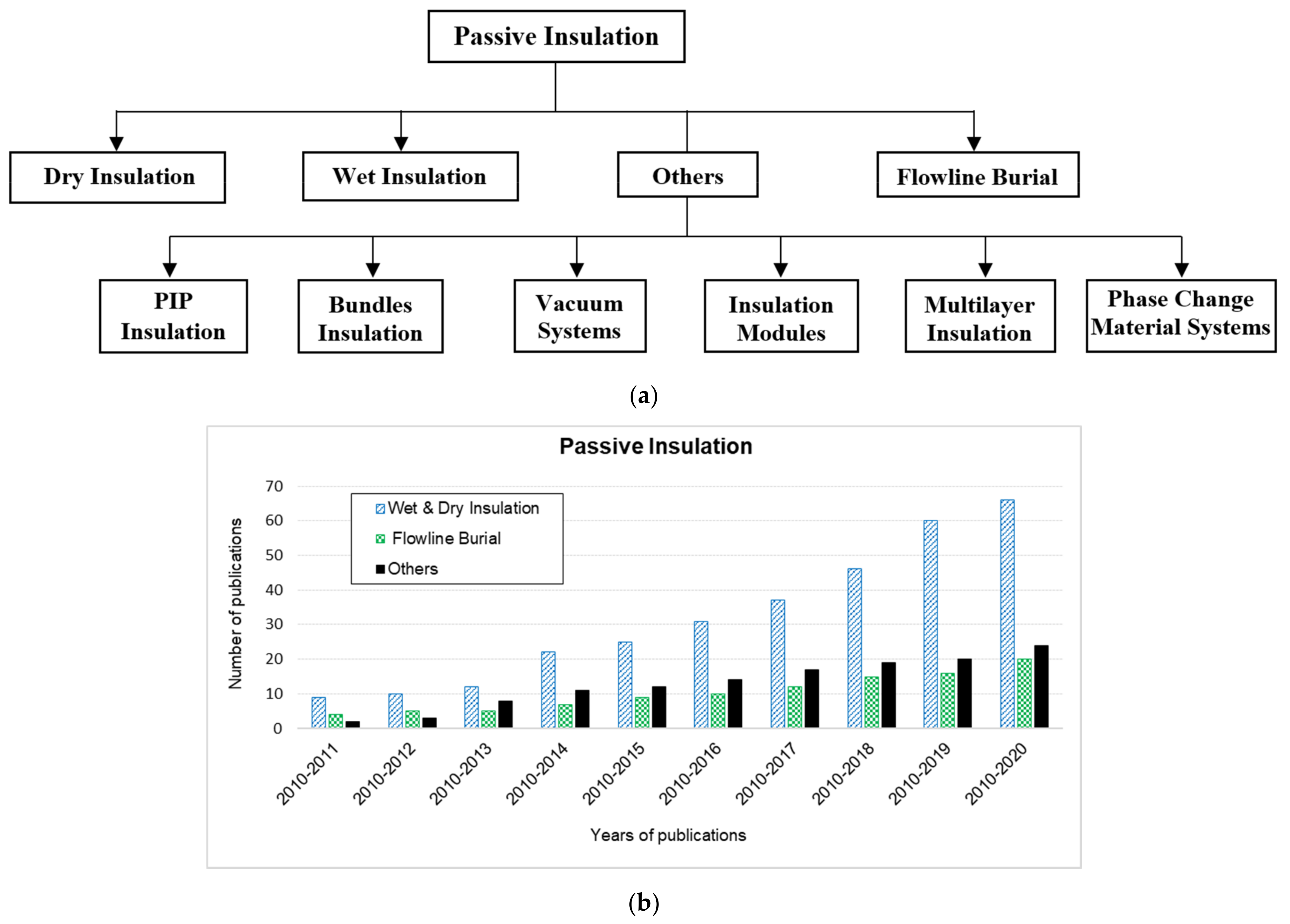
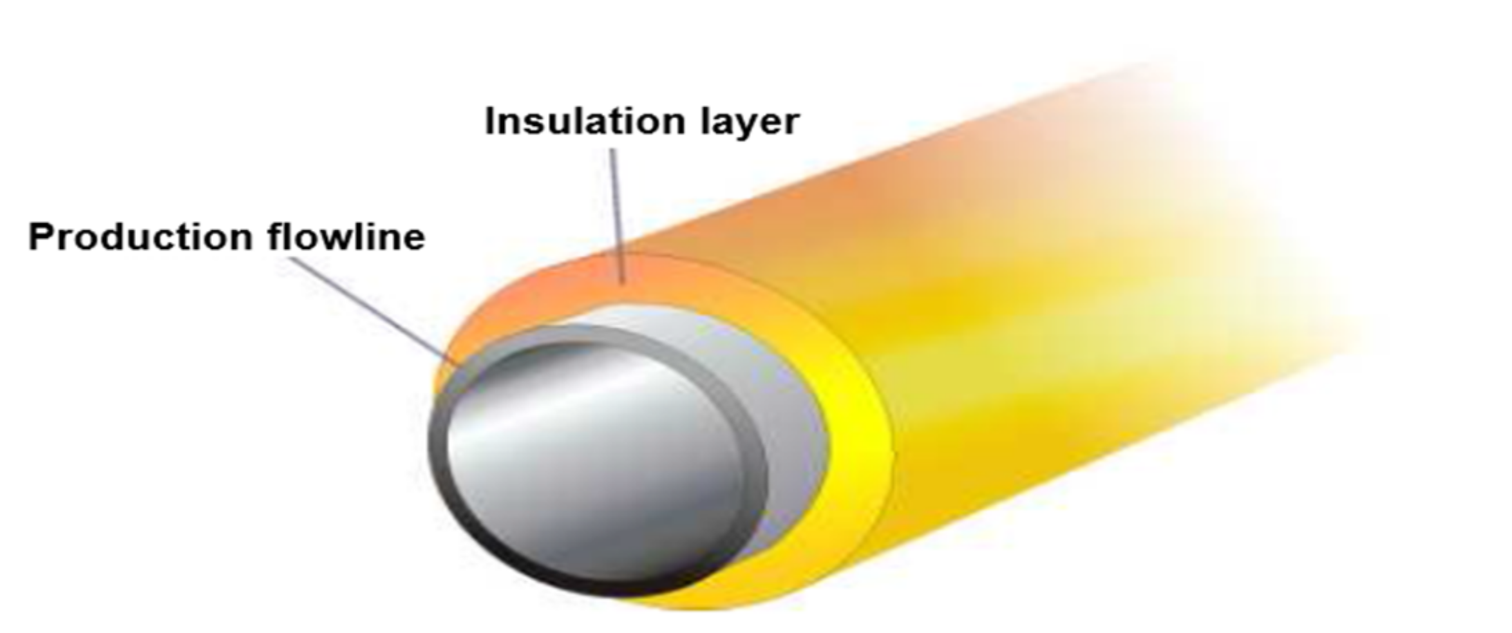
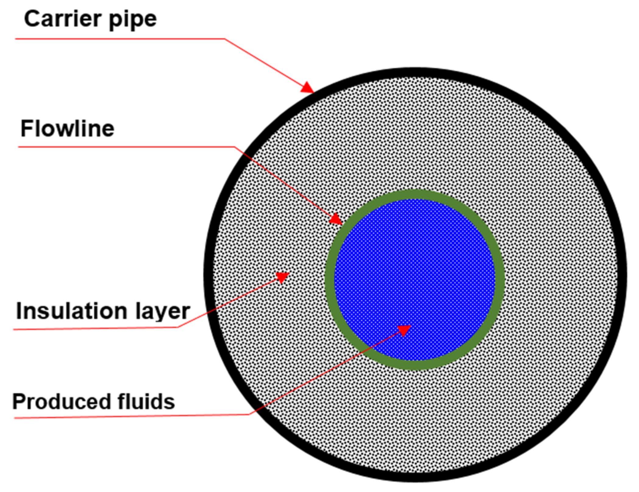
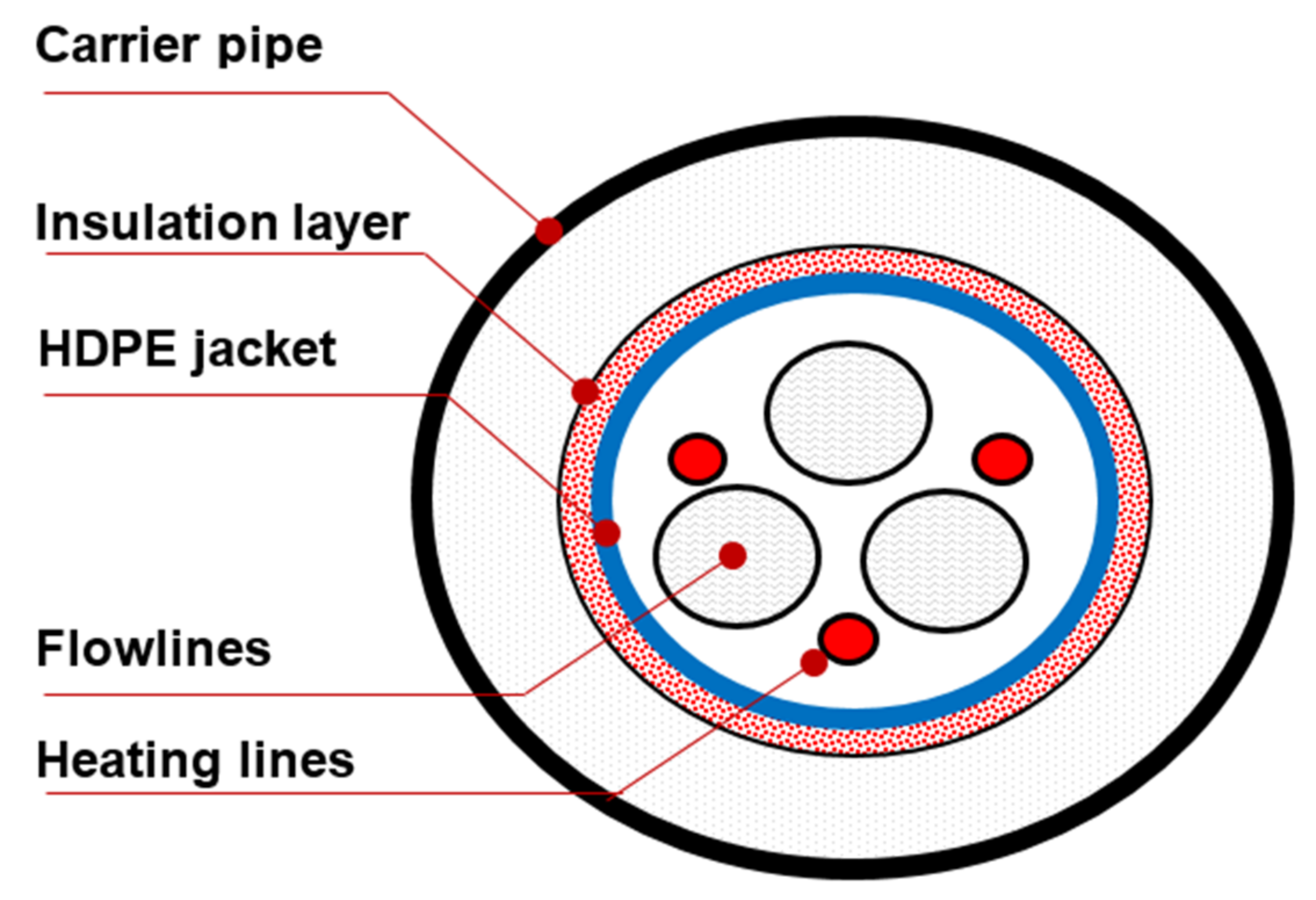
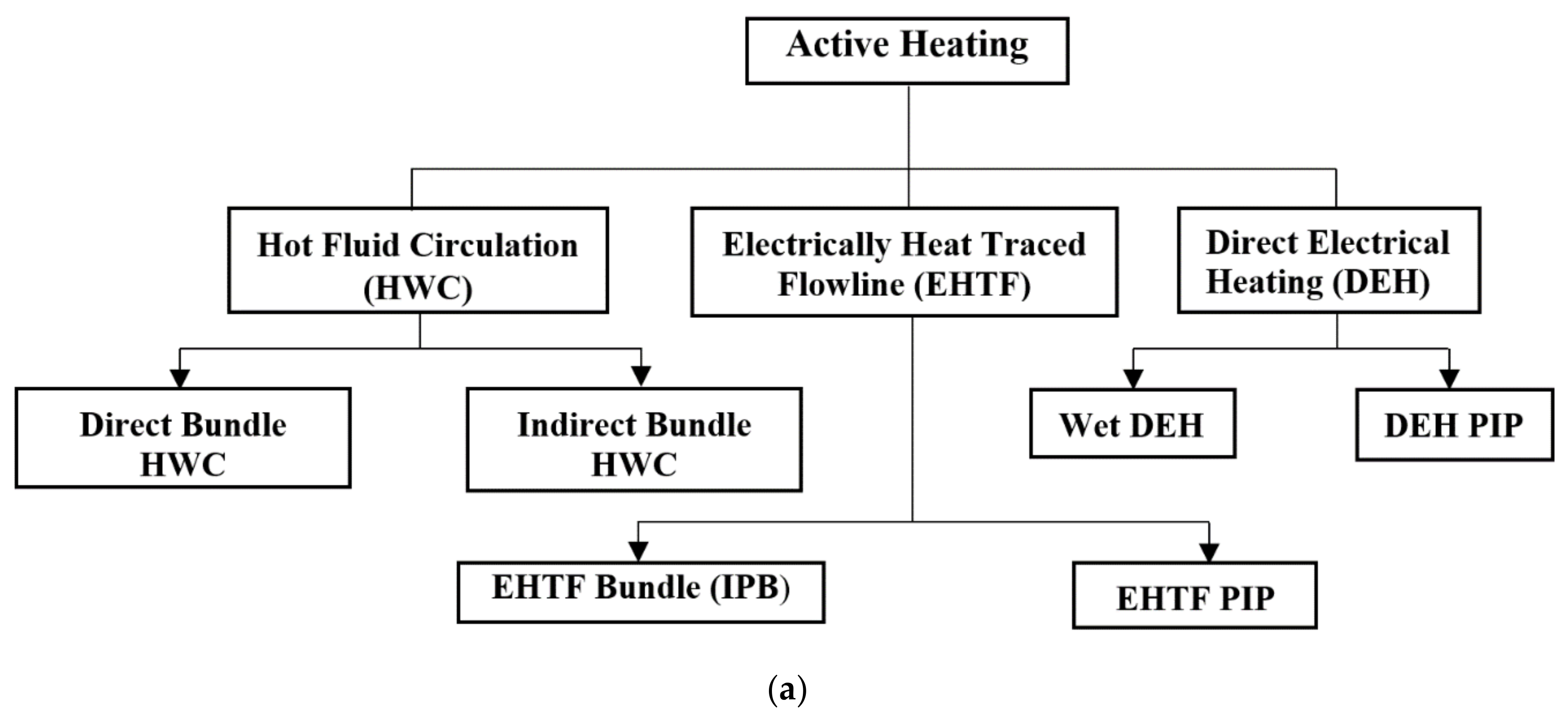
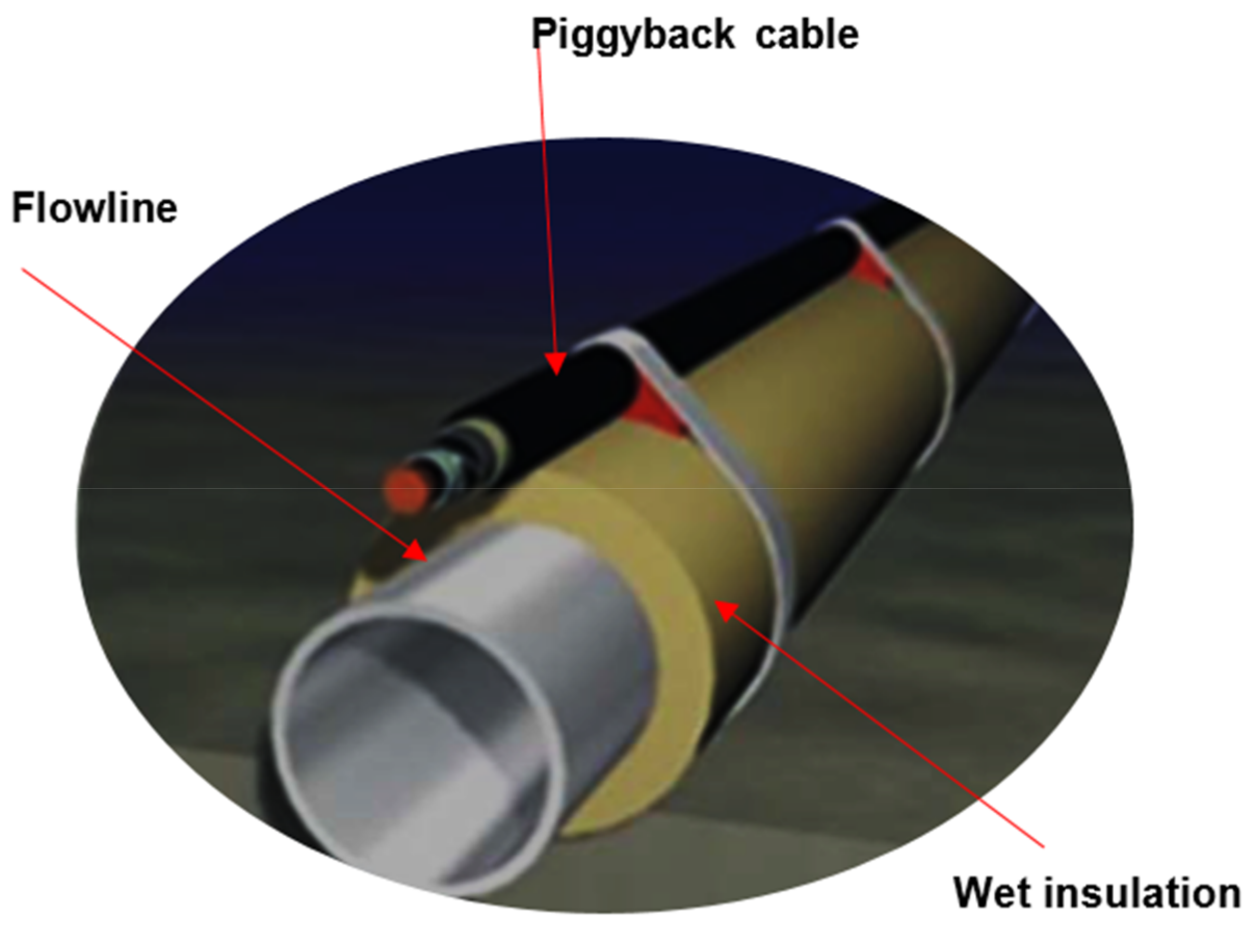
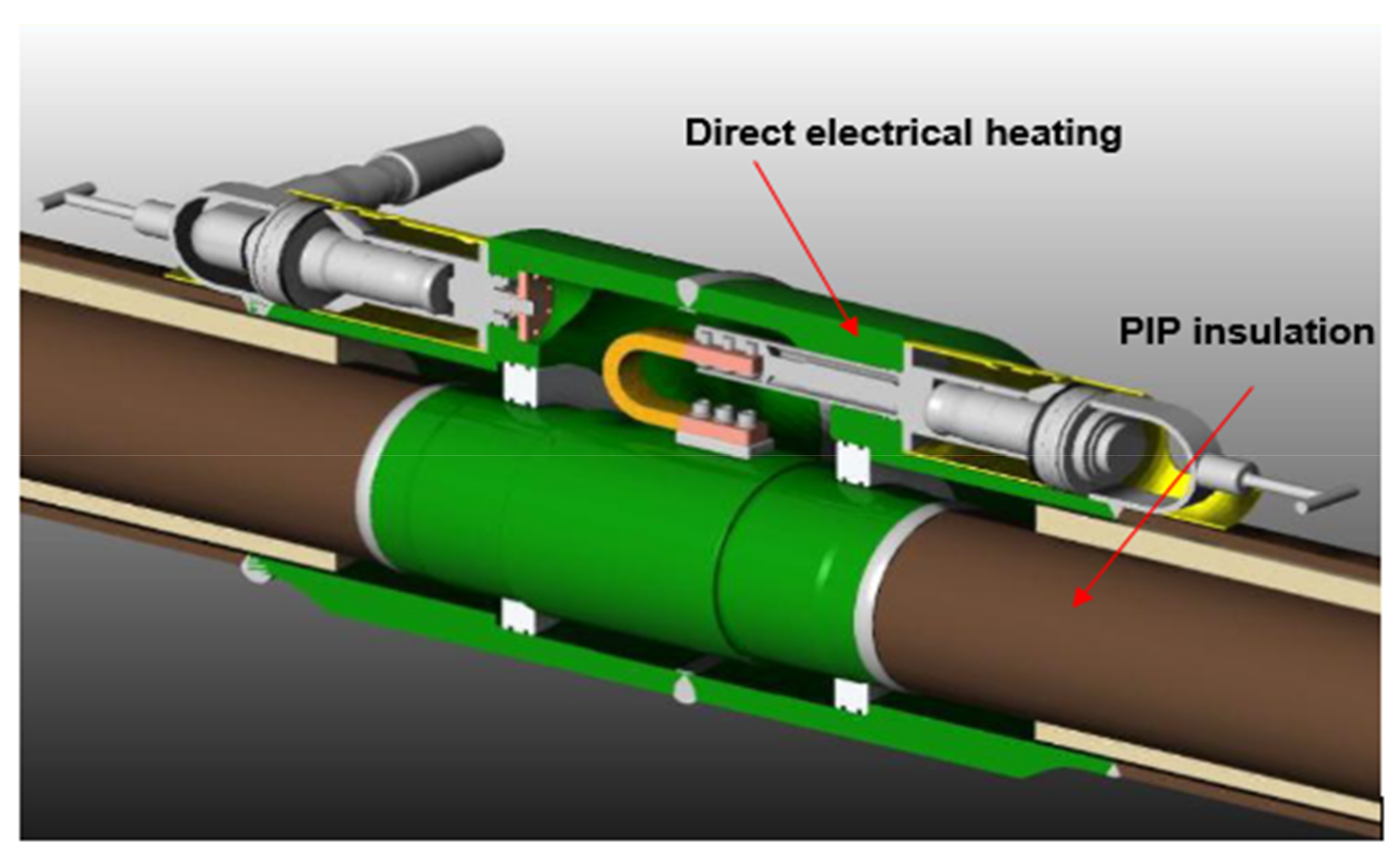
Table 1.
Summary of wet insulation properties.
| Insulation Material | U-Value W/m2 K | Density (kg/ m3) | Water Depth (m) | Service Temperature (°C) | Citations |
|---|---|---|---|---|---|
| Polyurethane (PU)—Solid. | 0.20 | 1153.33 | 115.60 | [82] | |
| Polypropylene (PP)—Solid | 0.22 | 897.03 | 2743.20 | 143.30 | |
| Syntactic PU | 0.12–0.15 | 608.70–848.98 | 91.40–2743.20 | 55–115.60 | |
| Syntactic PP | 0.13–0.22 | 592.68–800.92 | 115.60 | ||
| Syntactic Phenolic | 0.08 | 496.57 | 200 | ||
| Syntactic Epoxy | 0.10–0.14 | 592.68–720.83 | 1828.80–2743.20 | 71.11–100 | |
| Polypropylene (PP)—Solid | 0.22 | 900 | 3000 | 145 | [51,92] |
| Polypropylene (SPP)—syntactic PPF (e.g., carizite) | 0.13–0.22 | 600–800 | - | 115 | |
| Polypropylene (RPPF)—ReinforcedFoam combination | 0.16–0.18 | 600–800 | 600–3000 | 115–140 | |
| Polyurethane (PU)—Solid | 0.19–0.20 | 1150 | 115 | ||
| Polyurethane (SPU)—Syntactic (plastic beads) | 0.12–0.15 | 750–780 | 100 at 115 °C 300 at 90 °C | 70–115 | |
| Polyurethane (GSPU)-Glass Syntactic | 0.12–0.17 | 610–830 | 2000–3000 | 55–90 | |
| Polyurethane(RPUF)—Reinforced Foamcombination | 0.08 | 448 | - | - | |
| Phenolic Syntactic | 0.08 | 500 | - | 200 | |
| Epoxy Syntactic | 0.10–0.14 | 590–720 | 2000–3000 | 75–100 | |
| Epoxy Syntactic with Mini Spheres | 0.12 | 540 | - | 75 |
Table 2.
Thermal Properties of Pipe-In-Pipe Insulation Materials.
| Insulation Material | Density (Kg/m3) | Thermal Conductivity (W/m K) | U-Value (W/m2 K) | Annulus Gap (if any) | Maximum Temperature (° C) | Comments | Citations |
|---|---|---|---|---|---|---|---|
| Mineral Wool | 140 | 0.037 | 1.60 | Clearance | 700 | Rockwood or Glava, always combine with reflective Mylar film. | [51,72,92] |
| Aluminum Silicate Microsphere | 390–420 | 0.1 | 3.90 | None | 1000+ | Commonly known as fly ash, introduce to charge the annulus. | |
| Thermal Cement | 900–1200 | 0.26 | - | None | 200 | Presently been studied by a Joint Industry Project, to have collapse resistance with a decrease in pipe wall thickness. | |
| LD PU Foam | 60 | 0.030 | 0.76 | None | 147 | Prefabricated as a double-jointed or single system for the replacement project of Erskine. | |
| HS PU foam | 150 | 0.04 | 1.20 | None | 147 | ||
| Microporous Silica Blanket | 200–400 | 0.02 | 0.40 | Clearance | 900 | Cotton blanket, glass, titanium fibers and calcium-based powder. | |
| Closed-Cell Polyurethane Foam (CCPUF) | 48.06–96.11 | - | - | - | - | - | [82] |
| Open-Cell Polyurethane Foam (OCPUF) | 32.03–64.07 | - | - | - | - | - | |
| Polyisocyanurate Foam (PIF) | 28.83–32.03 | - | 1.08 | - | −182.78–148.89 | - | |
| Extruded Polystyrene | 96.11 | - | 1.47 | - | −182.78–73.88 | - | |
| Fiberglass | 56.06–88.10 | - | 1.36 | - | −17.78–454.44 | - | |
| Mineral Wool | 139.36 | - | 1.42 | - | 700 | - |
Table 3.
Thermal properties of vacuum systems.
| Insulation Material | Density (Kg/m3) | Thermal Conductivity (W/m K) | U-Value (W/m2 K) | Annulus Gap (if any) | Maximum Temperature (° C) | Comments | Citations |
|---|---|---|---|---|---|---|---|
| Vacuum Insulation Panels (VIPs) | 60–15 | 0.016–0.008 | 0.26 | Clearance | 160 | The foam of the shells is made with aluminum foil under the condition of vacuum and utilizes gas absorbing “getter” pills for free gas. | [51,72,92] |
| Vacuum Insulation Panels (VIPs) | 59.27–144.17 | - | 0.20–0.31 | - | 160 | - | [82] |
Table 4.
Comparison of the different passive insulation systems.
| Heat Management Technique | Advantages | Drawbacks | U-Value (W/m2 K) | Citations |
|---|---|---|---|---|
| External Integral Insulation (Multilayer Insulation included) |
|
| 1.7–5.0 | [51,85] |
| Insulation Bundle/ Module Systems |
|
| 2.0–8.00 | |
| PIP Insulation |
|
| 0.3–1.5 | |
| Vacuum Systems |
|
| <0.01 | |
| Burial Trenching |
|
| Insulation layers + soil insulation | |
| Thin Film/Multilayer[159] |
|
| Applied in Shell Oregano and Serrano, BP Marlin. | |
| Conventional Insulation |
|
| - | [50] |
| PIP Insulation |
|
| - | |
| Flowline Burial |
|
| - | |
| Phase Change Material (PCM) |
|
| [149] |
Table 5.
Advantages and drawbacks of Wet and Bundle HWC.
| Advantages | Drawbacks | Citations | |
|---|---|---|---|
| Design |
|
| [160] |
| Fabrication |
|
| |
| Installation |
|
| |
| System Efficiency/ Reliability |
|
|
Table 6.
DEH wet insulated flowline advantages and drawbacks.
| Advantages | Drawbacks | Citations | |
|---|---|---|---|
| Design |
|
| [176] |
| Fabrication |
|
| |
| Installation |
|
| |
| System Efficiency |
|
| |
| Reliability/ Reparability |
|
| |
| Design |
| [160] | |
| Fabrication |
|
| |
| Installation |
|
| |
| System Efficiency |
|
| |
| Reliability/Reparability |
|
|
Table 7.
Advantages and drawbacks of DEH-PIP compared to Wet-DEH.
| Advantages | Drawbacks | Citations | |
|---|---|---|---|
| Design |
|
| [176] |
| Fabrication |
|
| |
| Installation |
|
| |
| System Efficiency |
|
| |
| Reliability/ Reparability |
|
| |
| Design |
|
| [160] |
| Fabrication/ Installation |
|
| |
| System Efficiency/Reliability |
|
|
Table 8.
Advantages and drawbacks of EHTF-PIP.
| Advantages | Drawbacks | Citations | |
|---|---|---|---|
| Design |
|
| [176] |
| Fabrication |
|
| |
| Installation |
|
| |
| System Efficiency |
|
| |
| Reliability/ Reparability |
|
| |
| Design |
|
| [160] |
| Fabrication/ Installation |
| ||
| System Efficiency |
| – | |
| Reliability/Reparability |
|
|
Table 9.
Advantages and drawbacks of IPB.
| Advantages | Drawbacks | Citations | |
|---|---|---|---|
| Design/Fabrication/Installation |
|
| [160] |
| System Efficiency |
|
| |
| Reliability/Reparability |
|
|
Publisher’s Note: MDPI stays neutral with regard to jurisdictional claims in published maps and institutional affiliations. |
© 2021 by the authors. Licensee MDPI, Basel, Switzerland. This article is an open access article distributed under the terms and conditions of the Creative Commons Attribution (CC BY) license (http://creativecommons.org/licenses/by/4.0/).
Share and Cite
MDPI and ACS Style
Sunday, N.; Settar, A.; Chetehouna, K.; Gascoin, N. An Overview of Flow Assurance Heat Management Systems in Subsea Flowlines. Energies 2021, 14, 458. https://doi.org/10.3390/en14020458
AMA Style
Sunday N, Settar A, Chetehouna K, Gascoin N. An Overview of Flow Assurance Heat Management Systems in Subsea Flowlines. Energies. 2021; 14(2):458. https://doi.org/10.3390/en14020458
Chicago/Turabian StyleSunday, Nsidibe, Abdelhakim Settar, Khaled Chetehouna, and Nicolas Gascoin. 2021. "An Overview of Flow Assurance Heat Management Systems in Subsea Flowlines" Energies 14, no. 2: 458. https://doi.org/10.3390/en14020458
Note that from the first issue of 2016, this journal uses article numbers instead of page numbers. See further details here.