The Beneficial Effect of the Addition of Fly Ash on Reduction of the Size of Microcracks in the ITZ of Concrete Composites under Dynamic Loading


Department of Structural Engineering, Faculty of Civil Engineering and Architecture, Lublin University of Technology, Nadbystrzycka 40 str., 20-618 Lublin, Poland
Energies 2021, 14(3), 668; https://doi.org/10.3390/en14030668
Submission received: 4 January 2021
/
Revised: 25 January 2021
/
Accepted: 25 January 2021
/
Published: 28 January 2021
(This article belongs to the Section B: Energy and Environment)
Abstract
:The paper presents results of tests on the effect of the addition of fly ash (FA) in the amounts of 0%, 20%, and 30% by weight of cement on the interfacial microcracks in concrete composites subjected to dynamic loads. The analyses were carried out based on the results of the microstructural tests using a scanning electron microscope (SEM). The average width of the microcracks (Wc) in the interfacial transition zone (ITZ) of coarse aggregate with cement matrix was evaluated. During the studies beneficial effect of the addition of FA on reduction of the size of Wc in the ITZ of concrete composites under dynamic loading were observed. Based on obtained test results, it was found that using the 20% FA additive causes favorable changes in the microstructure of mature concrete. In this composite, the average value of Wc was lower by more than 40% compared to the result obtained for the reference concrete. In contrast, concrete containing 30% FA additive had greater microcracks in the ITZ area by over 60% compared to the material without additive. In all analyzed composites, an increase in the Wc value by almost 70% to over 110% in the case of occurrence of dynamic loads was also observed. This was the most evident in the case of concrete with a higher content of FA.
1. Introduction
Among the extensive activities promoting the development of sustainable construction, special attention is paid to replacing ordinary Portland cement (OPC) with other mineral components in the composition of the concrete mix. Such proposals are primarily aimed at reducing the negative effects associated with the burning of Portland clinker, from which OPC is later produced. Particularly adverse effects associated with the production processes of traditional cement binder are significant emission of greenhouse gases (GHG), mainly CO2, e.g., [1]; their excessive energy consumption, e.g., [2]; and relatively high production costs, e.g., [3].
Therefore, fly ash (FA) and ground granulated blast-furnace slag (GGBS) are currently used all over the world in significant amounts as a substitute for a part of the cement binder. These materials are the industrial by-products [4]. However, due to the fact that FA is generated as a waste in the heat and electricity generation processes in coal-fired power plants—which are still the dominant branch of the energy industry in many countries—this material is now considered as the most often used substitute for OPC [5,6,7,8,9,10].
Currently, 800 millions tonnes of the FA is produced in the world each year [11]. In 2031–2032, this quantity is expected to increase to 2100 million tonnes [12]. In Poland, approx. 20 million tonnes of FA is produced each year [13].
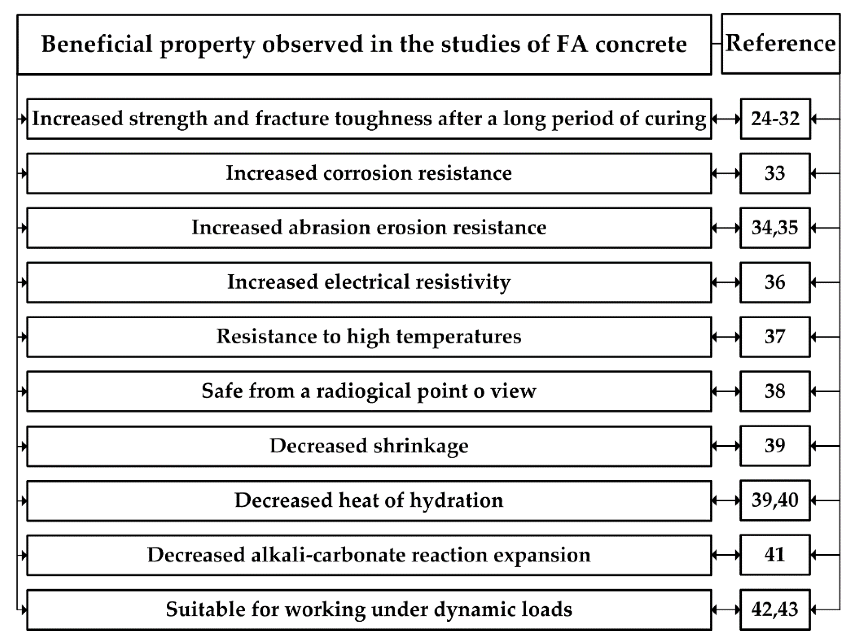
The use of FA as an active mineral additive to concrete results in an environmental and financial benefits related to, e.g., reduction in emission of harmful GHG to the atmosphere, reduction of heat and electricity consumption, as well as the reduction of the price of a modified binder [14,15,16,17,18,19,20]. Based on numerous studies to date—conducted on composites with FA for almost 90 years—it has also been proven that these materials have numerous advantages compared to traditional concretes. The main benefits of using FA in concrete are given in Figure 1. Furthermore, other relevant directions of recycling of FA are also presented in [21,22,23], and the examples are the use of FA for aluminum extraction, synthesis of geopolymers, and production of zeolites.
The beneficial properties of concretes with the addition of FA are mainly related to the grain structure of these materials and their high pozzolanic reactivity. The composition of FA is dominated by spherical, fine-grained particles with a well-developed surface. Their characteristic examples are shown in papers [2,38,44].
It should be noted that such morphology of FA grains causes their faster reaction during the processes of formation of the cement matrix structure, which implies numerous advantages for the mature composite (see Figure 1). One of the distinct advantages of using this pozzolanic additive in the composition of the concrete mix is the possibility to limit the development of the negative effects of dynamic loads in concrete structures. Dynamic loads acting both in an impact and cyclical manner cause faster initiation and more rapid propagation of microcracks in the concrete. This applies primarily to the weakest spots in the material structure, i.e., contact layers between the various phases of the composite. Therefore, it is very important to properly select the composition of the concrete mix in order to obtain the most homogeneous structure of cured concrete. This should apply to the cement matrix and its interfacial transition zones (ITZ) with the coarse aggregate grains. The papers [42,43] present the results of the research, which reveal that the width of the microcracks (Wc) among FA grains and the cement paste are several times smaller than the damages occurring in the ITZ area of coarse aggregate. Therefore, it has been shown that concretes with such a composition are a favorable material for use in dynamically loaded concrete structures.
However, it should be noted that the destruction of concrete structures subject to static and dynamic effects is determined by the quality of ITZ in the area of coarse aggregate grains [45,46,47,48,49,50]. It was proved in paper [50] that Wc in this zone is lower by almost 35% in the case of concretes modified with 20% FA additive. Increasing the amount of this microfiller in the binder composition by 10% causes negative effects in the form of an increase in the width of microcracks in the ITZ zone by more than 60%. However, the results presented in [50] relate to concretes subjected to static loads only. However, it should be emphasized that the situations when it is necessary to take into account dynamic loads in the analyses of concrete structures are numerous, e.g., [51,52,53,54,55,56,57,58,59,60,61]. Their summary is presented in detail in Section 2. Moreover, there are no studies in the literature that would present the microcrack test results in the area of ITZ of FA modified concretes, which would be the result of dynamic loads. In order to fill this gap in the literature, tests were carried out that assessed Wc occurring at the interface of coarse aggregate with the cement matrix. The presented experiments were conducted for the impact loads. The research investigated the changes in the size of microcracks occurring in the ITZ zone for concretes with two amounts of FA and unmodified composite. The results were compared with Wc values obtained for the same concretes under static load. The aim of the article was to demonstrate the benefits of using FA in the composition of the concrete mix in relation to structures in which intra-material damages may occur as a result of the action of dynamic loads. The proposed solutions are aimed at limiting the negative effects caused by dynamic actions in concrete and reinforced concrete structures by proposing an appropriate modification of the binder composition in the concrete mix.
2. Dynamic Loads in Concrete Structures
Modern building concrete and reinforced concrete structures more and more often require designers to include both static and dynamic loads in the calculations, e.g., [51]. Dynamic effects can be generated in a deterministic way, e.g., through the operation of machines or cranes and taken into account when designing dynamically loaded foundations, support structures, and crane beams [43,62,63,64,65,66,67]. Moreover, dynamic loads may also be the result of non-deterministic impacts such as wind gusts, which are important in the dynamic analysis of skyscrapers, earthquakes, road traffic, explosions in quarries, the impact of sea waves, and vibrations resulting from wheeled and railway vehicles [67,68,69].
The number and variety of dynamic loads acting on buildings and caused by both human activities and factors independent of human activity are significant [42,67,69]. However, two main criteria can be identified in the scope of building construction dynamics, mutually interpenetrating and complementing, based on which the breakdown takes place.
Dynamic influences in the civil engineering industry are conventionally divided into:
- (a)
- natural—independent of man, resulting from forces of nature. Such forces are transferred to the building through the ground or air in the form of wave and they constitute a kinetic extortion. Therefore, they include rapid changes in the air pressure (wind action) or ground movements (seismic actions).
- (b)
- civilization—resulting from intentional human activity. These forces depend on humans, but they are not always under their control. Such loads are transferred similarly as in the case of natural influences through the air and ground.
- (c)
- occurring inside buildings—normally associated with the operation of machines and equipment. This group includes forces that may cause motion excitation of structural elements, e.g., ceilings, walls, foundations, or other building’s components. The source of these loads can be clearly located and fully identified (e.g., fan installed inside the building) or accidental and not always precisely known (e.g., vibrations from the operation of the installation or caused by moving people in the building).
Depending on the source, vibrations can be divided into:
- (a)
- seismic—caused by rapid earth movements (earthquakes), which propagate from the Earth’s interior to the surface and then disperse over it,
- (b)
- paraseismic—caused by human dependent sources.
The above mentioned dynamic loads occurring in concrete structures may have very different origins. They were characterized in detail in [42]. These loads may also have a negative impact on the operation of concrete and reinforced concrete structures to a varying degree.
Therefore, in order to assess possible risks that may arise as a result of the occurrence of dynamic loads, a thorough dynamic diagnostics of such structures is needed [46,57,70,71]. After its completion, appropriate guidelines and operating conditions for such structures should be proposed. Their compliance should guarantee the safe use of a building.
There are four basic conditions for dynamically loaded concrete structures, i.e.,:
- strength,
- stiffness,
- structural,
- technological.
At this point, it should be noted that there are also other dynamic criteria to protect concrete structures from the harmful effects of this type of load. Such examples can be found in [72]. Nevertheless, the specificity of concrete structures is related to the occurrence of cracks in their structure. These discontinuities, under the influence of dynamic loads, may propagate in an uncontrolled manner, which could pose a risk of sudden failure or even a construction disaster. The deterioration of concrete structures usually begins when complex stress states occur in the structure. This implies the development of microcracks in the material structure under Mode I, Mode II, and Mode III fracture [73,74]. In such cases, mixed mode loading may also dominate [75,76]. From the above reasons, the structural condition seems to be the most crucial. This is due to the fact that structural condition supplements conditions resulting from serviceability requirements. These requirements include conditions of the limited crack openings, impermeability condition, condition of tensile stress absence, condition of not exceeding expansion joints openings, and condition of cracks or flaking plaster. These conditions have been formulated for specific types of structures or entire classes of structures. They depend to a large extent on the material and binders used. These issues are thoroughly discussed in [69].
Taking the above into account, the article analyzes how the material modification of the concrete with the use of pozzolan-active FA has an effect on the size of microcracks in the ITZ zone between the coarse aggregate and the cement matrix in the case of dynamic loads.
During the studies, new experiments in the evaluation of Wc of concrete composites with FA additives, which were subjected to dynamic loads, were applied. In order to emphasize the novelty of this research, it should be noted that various methods have been proposed so far to investigate nature of microcracks in concrete elements. The following methods were used for the theoretical, experimental, and numerical purposes. However, measurements of Wc with the use of precise Scanning Electron Microscopy (SEM) technique conducted on concrete specimens containing FA, which resulted from the impact of dynamic loads, have not been carried out and presented in the literature so far. Therefore, the proposed solution allowed for a more detailed understanding of cracking processes occurring in FA modified concretes subjected to dynamic loads. In addition, the compressive strength (fcm) of analyzed concrete composites were investigated.
3. Experimental Procedure
3.1. Materials
The tests were conducted with three types of concretes with different FA additives, i.e.,
- without the FA additive (FA-00),
- with 20% FA additive (FA-20),
- with 30% FA additive (FA-30).
Moreover, it should be noted that FA-00 concrete was treated as a reference. The methodology used to determine the composition of mixtures involved a replacement of a suitable amount of the cement volume (the weight volume content) in the mixture with a corresponding amount of the FA to ensure that the total amount of binding material is always constant. All mixtures had the same water/binding ratio w/B = 0.4.
The materials were taken from different sources in Poland. The following materials were used in order to prepare concrete mixes:
- ordinary Portland cement CEM I (OPC), from cement plant in Chełm,
- siliceous fly ash (FA) of class F with 85.09% of SiO2 + Al2O3 + Fe2O3, 0.65% of SO3, and 3.2% of Loss of Ignition (LOI), meeting the requirement of ASTM C618 standard from Puławy Power Station; moreover, there are (in addition to glass) four major crystalline components in the phase composition of the FA: quartz (SiO2), mullite (Al6Si2O13), magnetite (Fe3O4), and hematite (Fe2O3); the size of FA particles was fine grading with well-developed surfaces, whereas their average particle diameter was 102.035.
- pit sand 0–2 mm as fine aggregate, from natural deposit in Markuszów,
- natural gravel 2–8 mm as coarse aggregate, from natural deposit in Las Suwalski,
- plasticizer Basf Liquol BV-18,
- the laboratory pipeline water.
- The composition of prepared concrete mixes is shown in Table 1.
3.2. Compressive Strength Analysis
The uniaxial compression strengths were tested with the use of the following:
- a compression machine (Walter + Bai ag, type NS19/PA1; Löhningen, Switzerland) with a maximum load of 3000 kN,
- six cube specimens for each series of concrete with a side length of 150 mm,
- the loading rate of specimens between 0.5 MPa/s and 0.8 MPa/s.
3.3. Experiment with the Use of Dynamical Loads
The methodology of the conducted dynamic experiments was as follows:
- tests were carried out on the MTS 810 servo-hydraulic testing machine,
- during the experiment, a displacement controlled type of test with the MTS head velocity equal to 800 mm/s with a force equal to 80 kN was applied—this damaged the concrete specimen in a sudden manner similar to the tests on the impact tower; dynamic load conditions were in accordance with standards [77,78],
- after fracture toughness tests, fragments obtained from destruction zones of specimens for SEM examinations were gathered.
3.4. Microstructural Studies
The stages of microstructural studies and their main assumptions were as follows [42]:
- the microstructural testing was carried out using the electron scanning microscope (SEM). The equipment used was the FEI QUANTA 250 FEG scanning microscope, which was additionally equipped with a chemical composition analysis system based on energy dispersion scattering—the EDS EDAX.
- magnifications from 200 to 80.000 times were used,
- the specimens with dimensions of 10 × 10 × 3 mm were prepared,
- specimens were adhered to special holders with a two-sided carbon conductive tape; the tape’s task was to discharge electrical charges from the specimens while taking pictures and to achieve specimen surface conductivity; holders with the specimens were then placed on the microscope table, which had been placed in a microscope chamber, before the tests started,
- the specimens for testing were taken as raw, which means that the specimens before the test were not polished or prepared in any other way,
- however, the tests were performed in both the low and high vacuum; prior to testing in a high vacuum, the specimens were dried for one hour at the temperature of 70 ℃, and then they were sprayed with carbon or alloy of gold and palladium in a high vacuum sputter coater Q 150 E, the thickness of the coated layer was approx. 50 nm; the specimens tested in low vacuum did not require drying and spraying before the tests,
- six specimens were prepared from each series of concrete,
- 30 pictures were taken for each specimen (180 images were taken for each series of concrete),
- from 180 images the representative pictures were selected,
- pictures for all analyzed materials were taken at the same magnifications,
- approx. 3000 mm2 of each concrete batch area was observed in total,
- the captured pictures were images showing distinct damages in the ITZ area,
- during selection of pictures the attention was mainly drawn to the size of microcracks occurring in the ITZ area,
- the microcracks occurring in the ITZ area were measured to the nearest thousandth,
- for each specimen, microcracks were measured and shown in two magnifications, i.e., 1000 and 10,000 times,
- the SEM observation of microcracks in the tested specimens allowed for assessment of the average Wc for each type of concrete,
- average value of the Wc was calculated after observations of 30 representative SEM images.
- other characteristic spots, such as pores, cavities created after separating the FA grains from the matrix or cracks in the matrix, were also evaluated during microscopic examinations.
4. Results and Discussion
4.1. Analysis of Compressive Strength Test Results
Table 2 shows the average results of the compressive strength of FA concretes with statistic parameters (standard deviation—s and coefficient of variation—v). Based on the obtained results, it can be concluded that 20% FA additive causes an increase in fcm after 28 days of curing by 3.1%, while 30% FA additive causes a drop of this parameter by 5.1% (Table 2).
4.2. Evaluation of Macroscopic Cracks
An in-depth analysis of the macroscopic damages in the specimens was carried out before starting the assessment of the microstructure of concretes. It should be noted that such tests are an important element preceding the microstructural analyses [79,80,81,82,83,84]. The observed cracks were caused by the impact loads. As a result of this, the image of formation of damages in the specimens and the manner of their destruction, already at the stage of the evaluation of the obtained results, looked different from the case when the same cubes were tested under static load [28,54,73]. The following were analyzed:
- the size and appearance of cracks that formed on the surface of the specimens,
- characteristic cases of the destruction of cubes,
- macroscopic damages in sections of specimens.
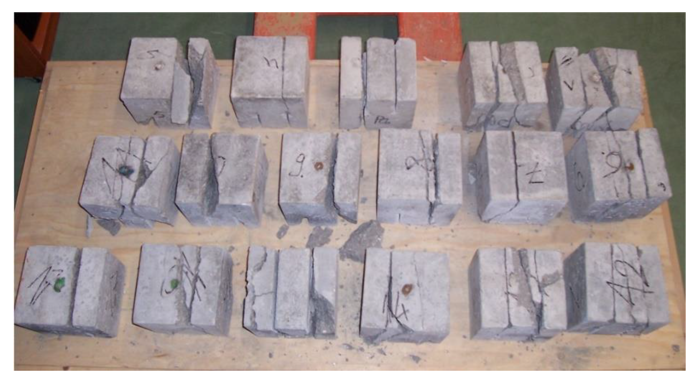
Figure 3 shows a batch of specimens after the conducted fracture toughness test as a result of the occurrence of dynamic loads. It can be seen that almost all cubes were significantly damaged and most of them were almost completely destroyed (see Figure 4). The specimens usually cracked suddenly on the extension of the initial cracks. Often there was a detachment of the sides of the cubes. In most cases, numerous surface defects were also observed in other parts of the specimens (Figure 3).
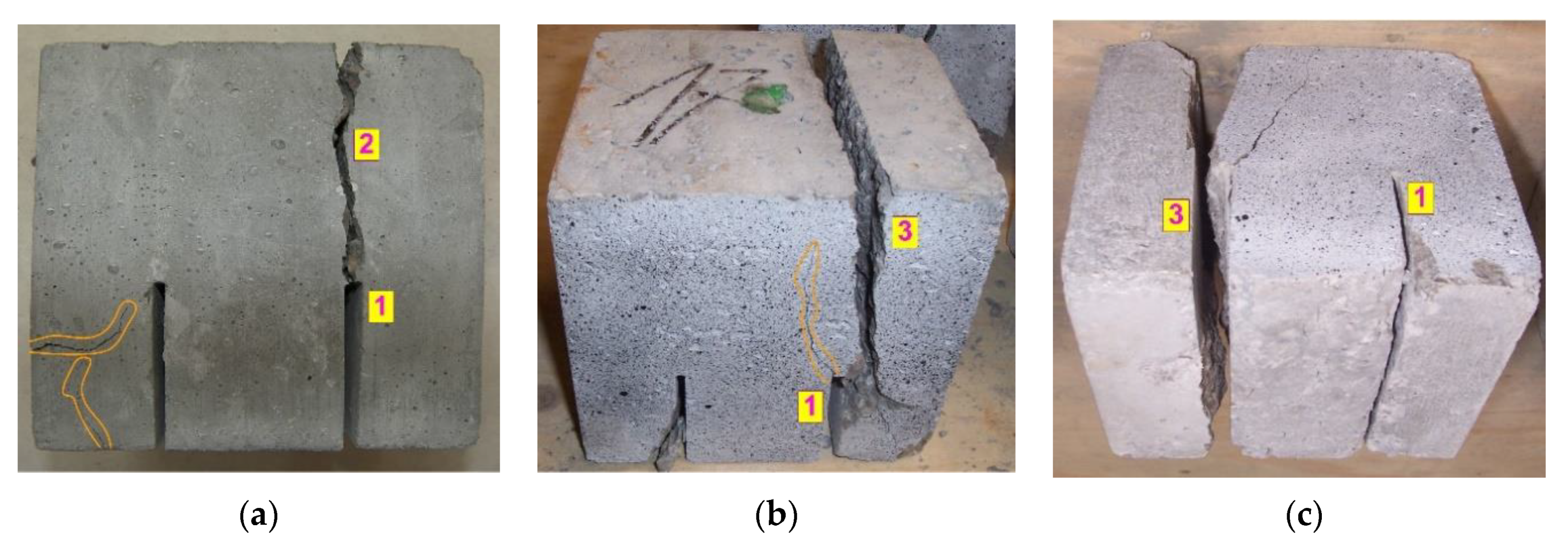
Figure 4 shows the view of three specimens from various perspectives with characteristic damages resulting from the impact loads. Furthermore, additional damages formed in various zones of the specimens as a result of strong dynamic actions are marked in orange in this figure. The characteristic images observed in the research were as follows:
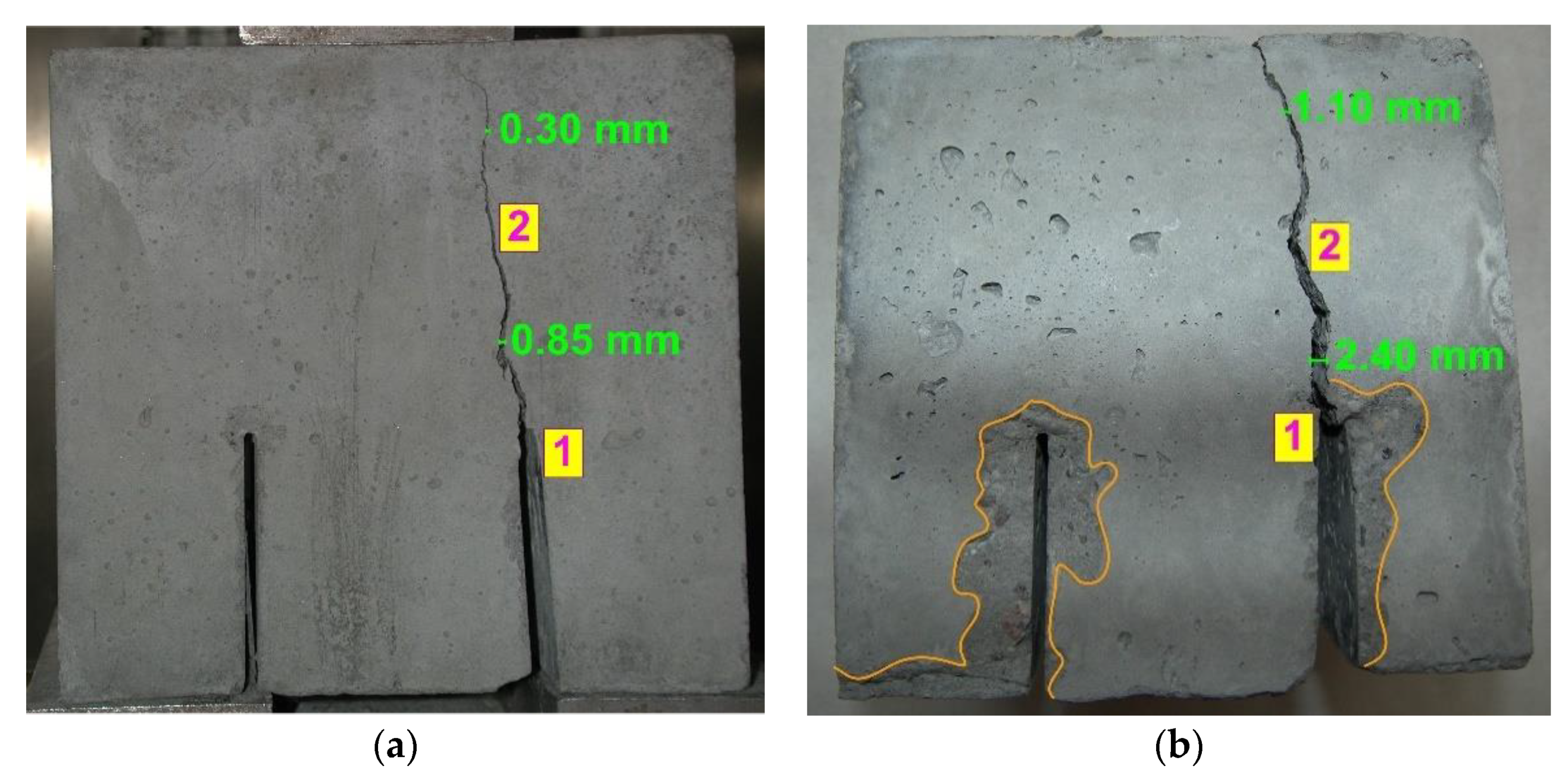
In order to more accurately illustrate the differences that occur in the macroscopic images of the destruction of specimens, after the conducted fracture toughness tests, under static and dynamic loads, Figure 5 shows a view of two cubes of FA-30 concrete with crack widths measured on their surfaces. The figure shows the cubes with very similar shapes of the surface cracks. Nevertheless, it can be seen that both cases are clearly different from each other. First of all, the crack width in the specimen after the impact test, shown in Figure 4b, is much greater in the lower part in the area of the tip of the initial crack and in the upper part, at the end of its propagation. The differences in the measured crack widths are approx. three times greater in the case of the cube shown in Figure 4b. Additionally, numerous other surface damages were observed for the cube visible on the right side (marked in orange) (Figure 5b). Such defects are not visible on the specimen tested under static load (Figure 5a).
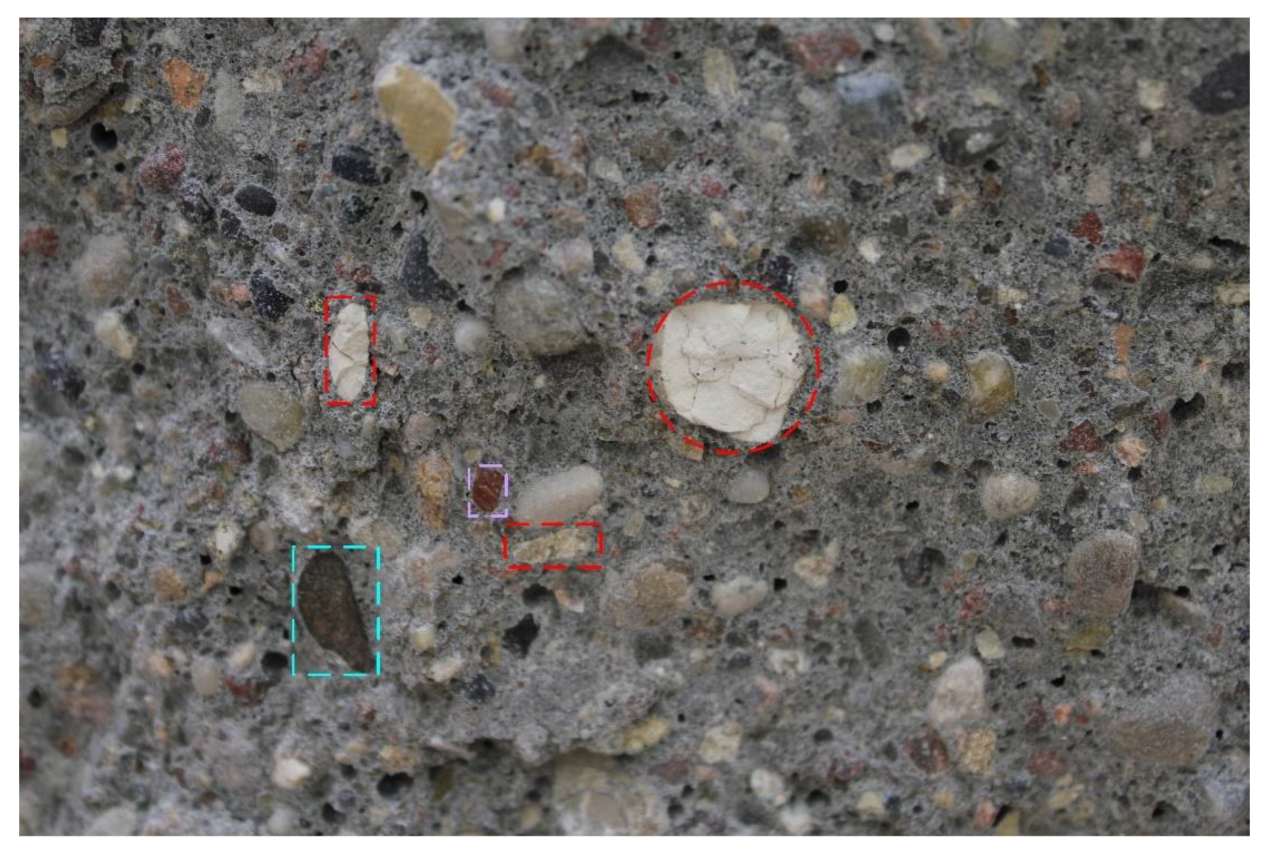
The inspection of concrete sections was carried out at the last stage of the macroscopic assessment of damages in the tested specimens. Figure 6 shows a characteristic example of damages occurring in the concrete structures exposed to dynamic actions. It shows that the most of the aggregates sheared as a result of strong dynamic actions. This is also confirmed by the research presented in paper [42]. Figure 6 shows the colors of different types of aggregates that underwent sharp-edged damages during the tests. As the gravel aggregate used to prepare the specimens was a mixture of minerals from different types of rocks, each color refers to a different type of filler, i.e., red—limestone, blue—basalt, and violet—dolomite.
On the basis of the cross-section view shown in Figure 6, it is clearly visible that the damages due to shear concerned fillers from all types of separated rocks. The defects affected limestone aggregates with low strength parameters and basalt aggregates with very good mechanical characteristics. On this basis, it could be predicted that the microscopic images would also show significant damages in the ITZ area between the coarse aggregate and the cement matrix.
4.3. Analysis of Microcrack Width (Wc) in the ITZ Area
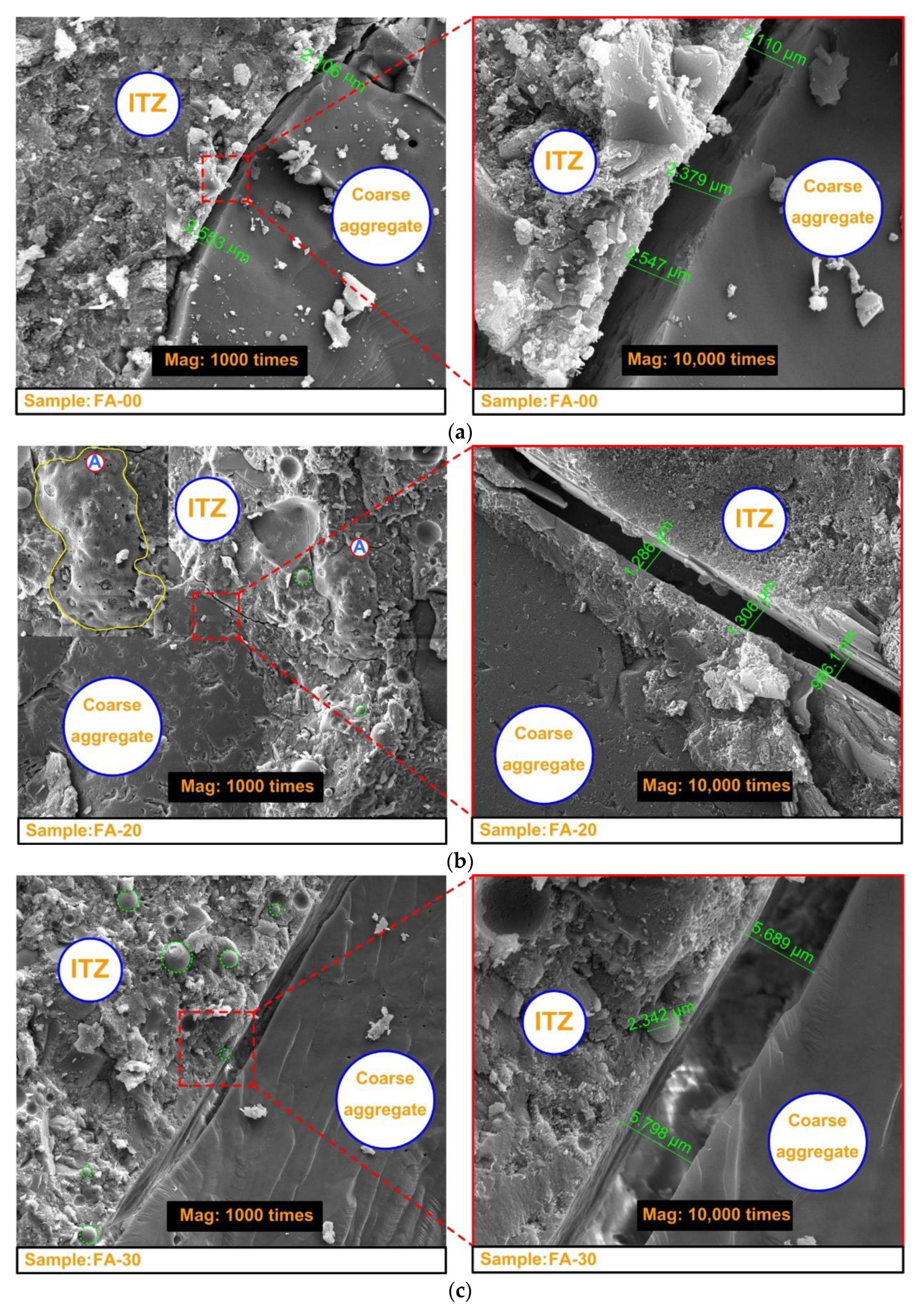
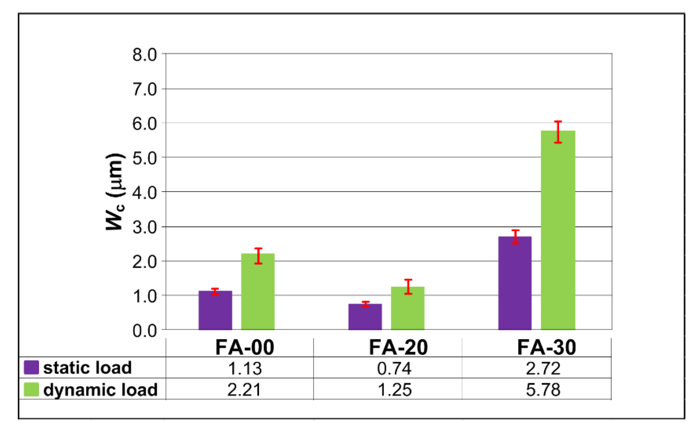
The sample representative SEM images made for all types of analyzed composites are presented in Figure 7, whereas the observed average Wc with error bars are shown in Figure 8. For comparison, Figure 8 also presents the results of measurements of microcracks in the ITZ area, made for concretes subjected to static loads. Furthermore, in order to show the obtained research results even more precisely, Table 3 presents the percentage increases of analyzed parameter, i.e., Wc in relation to the values that were obtained for the reference concrete. As comparison values, representing 100%, the results for FA-00 were assumed. The results obtained for modified concrete were characterized by a decrease or increase of given parameters in relation to the base value. The values obtained for both static and dynamic loads were taken into account (Table 3).
When analyzing the SEM images shown in Figure 7, it should be stated that in all of the assessed concretes, the damages in the ITZ area were characteristic for the case of dynamic loads. They were also consistent with the macroscopic images of the damaged grains shown in Figure 6. In each of the composites, sharp-edged damages of coarse aggregate grains (Figure 7) and microcracks of much larger sizes were observed than in the case of damages caused by static loads (Figure 8). The lowest Wc values were recorded for FA-20 concrete, while the highest werein the composites with 30% FA additive. Therefore, such results were qualitatively consistent with the results obtained when measuring microcracks that formed under static loads (Figure 8) [50].
Furthermore, 20% FA additive caused a distinct strengthening of the concrete structure in the ITZ area due to the intensive pozzolanic reactions. This phenomenon was observed in the picture shown in Figure 7b, detail “A”. The structure of the matrix in this material was compact, which meant that in this composite, under static and dynamic loads, microcracks in the ITZ area were the smallest (Figure 8). The highest Wc values were recorded for FA-30 concrete. Additionally, numerous unreacted FA grains in this composite (green border in Figure 7c) and spots after the separation of FA grains from the matrix were visible. This resulted in a weakening of its structure.
In all analyzed concretes, the microcracks were greater in the case of dynamic loads. The values Wc increased most clearly in FA-30 concrete by over 110%, while to the smallest extent in FA-20 concrete, only by less than 70%. In the reference concrete, an increase in Wc by less than 100% was recorded (Figure 8).
Additionally, the relative changes in Wc compared to the values obtained for the reference concrete were more pronounced in the case of dynamic loads in the concrete specimens. It was observed that Wc value for FA-20 concrete decreased by more than 40% (more by 10% than in the case of static loads), while for FA-30 concrete it increased by over 160% (more by 20% than in the case of static loads) (Table 3).
Therefore, the tests showed that siliceous FA as active filing material has beneficial effect on the delay of the destructive processes in the material subjected to dynamic loads (Table 3) and on the increase of the material’s compressive strength (Table 2).
Therefore, it can be concluded that concrete with 20% FA additive is—due to the reduction of intra-material cracks—an ideal material to be used in structures subjected to both static and dynamic loads. On the other hand, it is not recommended to use concretes containing 30% FA in structures exposed to dynamic loads.
5. Conclusions
Based on the obtained test results, the following conclusions can be drawn:
- the siliceous FA as an active additive in the amount of 20% and 30% changes the microcrack widths (Wc) of concrete composites subjected to dynamic loads,
- composite with 20% FA are characterized by smallest microcrack width in the ITZ in comparison to the unmodified concrete,
- the greatest microcrack width in the ITZ area in concrete containing 30% FA were observed,
- the average values Wc were qualitatively consistent with the results obtained when measuring microcracks caused by static loads (Figure 8),
- in all analysed concretes, the microcracks were greater in the case of dynamic loads when compared to Wc values obtained under static loads (Figure 8),
- sharp-edged damages of the coarse aggregate grains occur (Figure 6) under dynamic loads in the sections of concrete elements,
- concrete with 20% fly ash additive is an ideal material to be used in structures subjected to both static and dynamic loads,
- it is not recommended to use concretes containing 30% fly ash in structures exposed to dynamic loads,
- it should be mentioned that experiments of concretes with the siliceous fly ash gave the results presented in this article; composites containing calcareous fly ash may give different results; therefore, it is also planned to conduct similar tests on concretes modified with calcareous fly ash.
Funding
This research received no external funding.
Institutional Review Board Statement
Not applicable.
Informed Consent Statement
Not applicable.
Data Availability Statement
No new data were created or analyzed in this study. Data sharing is not applicable to this article.
Acknowledgments
This work was financially supported by Ministry of Science and Higher Education of Poland within the statutory research number FN15/ILT/2021.
Conflicts of Interest
The author declare no conflict of interest.
References
- Abolhasani, A.; Nazarpour, H.; Dehestani, M. Effects of silicate impurities on fracture behavior and microstructure of calcium aluminate cement concrete. Eng. Fract. Mech. 2021, 242, 107446. [Google Scholar] [CrossRef]
- Golewski, G.L. Energy savings associated with the use of fly ash and nanoadditives in the cement composition. Energies 2020, 13, 2184. [Google Scholar] [CrossRef]
- Szostak, B.; Golewski, G.L. Effect of nano admixture of CSH on selected strength parameters of concrete including fly ash. IOP Conf. Ser. Mater. Sci. Eng. 2018, 416, 012105. [Google Scholar] [CrossRef]
- Giergiczny, Z. Fly ash and slag. Cem. Concr. Res. 2019, 124, 105826. [Google Scholar] [CrossRef]
- Zhang, P.; Gao, Z.; Wang, J.; Guo, J.; Hu, S.; Ling, Y. Properties of fresh and hardened fly ash/slag based geopolymer concrete: A review. J. Clean. Prod. 2020, 270, 122389. [Google Scholar] [CrossRef]
- Zhang, R.; Guo, F.; Xia, Y.; Tan, J.; Xing, Y.; Gui, X. Recovering unburned carbon from gasification fly ash using saline water. Waste Manag. 2019, 98, 29–36. [Google Scholar] [CrossRef]
- Golewski, G.L.; Gil, D.M. Studies of fracture toughness in concretes containing fly ash and silica fume in the first 28 days of curing. Materials 2021, 14, 319. [Google Scholar] [CrossRef]
- Kovacik, J.; Marsavina, L.; Linul, E. Poisson’s ratio of closed-cell aluminum foams. Materials 2018, 11, 1904. [Google Scholar] [CrossRef] [Green Version]
- Raheel, M.; Rahman, F.; Ali, Q. A stoichiometric approach to find optimum amount of fly ash needed in cement concrete. SN Appl. Sci. 2020, 2, 1100. [Google Scholar] [CrossRef]
- Chen, Y.-G.; Guan, L.-L.; Zhu, A.-Y.; Chen, W.-J. Foamed concrete containing fly ash: Properties and application to backfilling. Constr. Build. Mater. 2021, in press. [Google Scholar]
- Belviso, C. State-of-the-art applications of fly ash from coal and biomass: A focus on zeolite synthesis processes and issues. Progr. Ener. Combus. Sci. 2018, 65, 109–135. [Google Scholar] [CrossRef]
- Hemalatha, T.; Ramaswamy, A. A review on fly ash characteristics—Towards promoting high volume utilization in developing sustainable concrete. J. Clean. Prod. 2017, 147, 546–559. [Google Scholar] [CrossRef]
- Kurdowski, W. Cement and Concrete Chemistry; Springer: New York, NY, USA; London, UK, 2014. [Google Scholar]
- Suchorab, Z.; Franus, M.; Barnat-Hunek, D. Properties of fibrous concrete made with plastic fibers from E-Waste. Materials 2020, 13, 2414. [Google Scholar] [CrossRef]
- Zhang, P.; Han, S.; Golewski, G.L.; Wang, X. Nanoparticle-reinforced building materials with applications in civil engineering. Advanc. Mech. Eng. 2020, 12, 1–4. [Google Scholar] [CrossRef]
- Szeląg, M. Development of cracking patterns in modified cement matrix with microsilica. Materials 2018, 11, 1928. [Google Scholar] [CrossRef] [PubMed] [Green Version]
- Szcześniak, A.; Zychowicz, J.; Stolarski, A. Influence of fly ash additive on the properties of concrete with slag cement. Materials 2020, 13, 3265. [Google Scholar] [CrossRef] [PubMed]
- Sadowski, T.; Golewski, G.L. A failure analysis of concrete composites incorporating fly ash during torsional loading. Compos. Struct. 2018, 183, 527–535. [Google Scholar] [CrossRef]
- Li, H.; Sun, H.; Tian, J.; Yang, Q.; Wan, Q. Mechanical and ultraconic testing of self-compacting concrete. Energies 2019, 12, 2187. [Google Scholar] [CrossRef] [Green Version]
- Li, H.; Sun, H.; Zhang, W.; Gou, H.; Yang, Q. Study on mechanical properties of self-compacting concrete and its filled in-line multi-cavity steel tube bundle shear wall. Energies 2019, 12, 3466. [Google Scholar] [CrossRef] [Green Version]
- Valeev, D.; Kunilova, I.; Shoppert, A.; Salazar-Concha, C.; Kondratiev, A. High-pressure HCl leaching of coal ash to extract Al into a chloride solution with further use as a coagualnt for water treatment. J. Clean. Prod. 2020, 276, 123206. [Google Scholar] [CrossRef]
- Amran, M.; Debbarma, S.; Ozbakkaloglu, T. Fly ash-based aco-friendly geopolymer concrete: A critical review of the long-term durability properties. Constr. Build. Mater. 2021, 270, 121857. [Google Scholar] [CrossRef]
- Ameh, A.E.; Eze, C.P.; Antunes, E.; Cornelius, M.-L.U.; Musyoka, N.M.; Petrik, L.F. Stability of fly ash-based BEA-zeolite in hot liquid phase. Catal. Tod. 2020, 357, 416–424. [Google Scholar] [CrossRef]
- Golewski, G.L.; Sadowski, T. A study of mode III fracture toughness in young and mature concrete with fly ash additive. Solid State Phenom. 2016, 254, 120–125. [Google Scholar] [CrossRef]
- Gil, D.M.; Golewski, G.L. Potential of siliceous fly ash and silica fume as a substitute of binder in cementitious concrete. E3S Web Conf. 2018, 49, 00030. [Google Scholar] [CrossRef] [Green Version]
- Gil, D.M.; Golewski, G.L. Effect of silica fume and siliceous fly ash addition on the fracture toughness of plain concrete in mode I. IOP Conf. Ser. Mater. Sci. Eng. 2018, 416, 012065. [Google Scholar] [CrossRef]
- Golewski, G.L. An analysis of fracture toughness in concrete with fly ash addition, considering all models of cracking. IOP Conf. Ser. Mater. Sci. Eng. 2018, 416, 012029. [Google Scholar] [CrossRef] [Green Version]
- Golewski, G.L.; Sadowski, T. Experimental investigation and numerical modeling fracture processes in fly ash concrete at early age. Solid State Phenom. 2012, 188, 158–163. [Google Scholar] [CrossRef]
- Golewski, G.L. Effect of fly ash addition on the fracture toughness of plain concrete at third model of fracture. J. Civ. Eng. Manag. 2017, 23, 613–620. [Google Scholar] [CrossRef] [Green Version]
- Golewski, G.L.; Sadowski, T. The fracture toughness the KIIIC of concretes with fly ash (FA) additive. Constr. Build. Mater. 2017, 143, 444–454. [Google Scholar] [CrossRef]
- Golewski, G.L. Generalized fracture toughness and compressive strength of sustainable concrete including low calcium fly ash. Materials 2017, 10, 1393. [Google Scholar] [CrossRef] [Green Version]
- Golewski, G.L. Effect of curing time on the fracture toughness of fly ash concrete composites. Compos. Struct. 2018, 185, 105–112. [Google Scholar] [CrossRef]
- Chindaprasirt, P.; Rukzon, S. Strength, porosity and corrosion resistance of ternary blend Portland cement, rice husk ash and fly ash mortar. Constr. Build. Mater. 2008, 22, 1601–1606. [Google Scholar] [CrossRef]
- Cai, X.; He, Z.; Tang, S.; Chen, X. Abrasion erosion characteristics of concrete made with moderate heat Portland cement, fly ash and silica fume using sandblasting test. Constr. Build. Mater. 2016, 127, 804–814. [Google Scholar] [CrossRef]
- Malazdrewicz, S.; Sadowski, Ł. An intelligent model for the prediction of the depth of the wear of cementitious composite modified with high-calcium fly ash. Compos. Struct. 2020, 113234. [Google Scholar] [CrossRef]
- Jingjing, L.; Fusheng, Z.; Long, X.; Bo, K.; Xiaohui, T.; Yongfeng, D.; Chengbin, Y. Mechanisms of stabilized/solidified heavy metal contaminated soils with cement-fly ash based on electrical resistivity measurements. Measurement 2019, 141, 85–94. [Google Scholar]
- Nadeem, A.; Memon, S.A.; Lo, T.Y. The performance of fly ash and metakaolin concrete at elevated temperatures. Constr. Build. Mater. 2014, 62, 67–76. [Google Scholar] [CrossRef]
- Golewski, G.L. Studies of natural radioactivity of concrete with siliceous fly ash addition. Cem. Wapno Beton 2015, 2, 106–114. [Google Scholar]
- Hu, X.; Shi, C.; Shi, Z.; Tong, B.; Wang, D. Early age shrinkage and heat of hydration of cement-fly ash-slag ternary blends. Constr. Build. Mater. 2017, 153, 857–865. [Google Scholar] [CrossRef]
- Szostak, B.; Golewski, G.L. Improvement of strength parameters of cement matrix with the addition of siliceous fly ash by using nanometric C-S-H seeds. Energies 2020, 13, 6734. [Google Scholar] [CrossRef]
- Joshaghani, A. The effect of trass and fly ash in minimizing alkali-carbonate reaction in concrete. Constr. Build. Mater. 2017, 150, 583–590. [Google Scholar] [CrossRef]
- Golewski, G.L. A novel specific requirements for materials used in reinforced concrete composites subjected to dynamic loads. Compos. Struct. 2019, 223, 110939. [Google Scholar] [CrossRef]
- Golewski, G.L. A new principles for implementation and operation of foundations for machines: A review of recent advances. Struct. Eng. Mech. 2019, 71, 317–327. [Google Scholar]
- Golewski, G.L. Changes in the fracture toughness under mode II loading of low calcium fly ash (LCFA) concrete depending on ages. Materials 2020, 13, 5241. [Google Scholar] [CrossRef] [PubMed]
- Li, Y.; Fu, T.; Wang, R.; Li, Y. An assessment of microcracks in the interfacial transition zone of recycled concrete aggregates cured by CO2. Constr. Build. Mater. 2020, 236, 117543. [Google Scholar] [CrossRef]
- Congro, M.; Roehl, D.; Mejia, C. Mesoscale computational modeling of the mechanical behavior of cement composite materials. Compos. Struct. 2020, 113137. [Google Scholar] [CrossRef]
- Li, X.; Zhang, Q.; Mao, S. Investigation of the bond strength and microstructure of the interfacial transition zone between cement paste and aggregate modified by Bayer red mud. J. Hazard. Mater. 2021, 403, 123482. [Google Scholar] [CrossRef] [PubMed]
- Gao, Y.; Jing, H.; Zhou, Z.; Shi, X.; Li, L.; Fu, G. Roles of carbon nanotubes in reinforcing the interfacial transition zone and permeability of concrete under different water-to-cement ratios. Constr. Build. Mater. 2020, in press. [Google Scholar]
- Wu, K.; Hu, Y.; Zhang, L.; Su, Y.; Han, J.; Yang, Z.; De Shutter, G. Quantitative evaluation of interfacial transition zone of sustainable concrete with recycled and steel slag as aggregate. Struct. Concr. 2020, 2020, 1–13. [Google Scholar]
- Golewski, G.L. The influence of microcrack width on the mechanical parameters in concrete with the addition of fly ash: Consideration of technological and economical benefit. Constr. Build. Mater. 2019, 197, 849–861. [Google Scholar] [CrossRef]
- Soroushian, P.; Choi, K.-B.; Alhamad, A. Dynamic constitutive behavior of concrete. ACI J. 1986, 83, 251–259. [Google Scholar]
- Stolarski, A.; Cichorski, W.; Szcześniak, A. Non-classical model of dynamic behaviour of concrete. Appl. Sci. 2019, 9, 2590. [Google Scholar] [CrossRef] [Green Version]
- Szcześniak, A.; Stolarski, A. Dynamic relaxation method for load capacity analysis of reinforced concrete elements. Appl. Sci. 2018, 8, 396. [Google Scholar] [CrossRef] [Green Version]
- Kim, H.-G.; Kim, B.-J. Design optimization of conical concrete support structure for offshore wind turbine. Energies 2020, 13, 4876. [Google Scholar] [CrossRef]
- Yang, X.; Sotiropoulos, F. A review on the meandering of wind turbine wakes. Energies 2019, 12, 4725. [Google Scholar] [CrossRef] [Green Version]
- Magnusson, J.; Hallgren, M.; Ansell, A. Shear in concrete structures subjected to dynamic loads. Struct. Concr. 2014, 15, 55–65. [Google Scholar] [CrossRef]
- Zhang, B.; Zhang, X.; Zhong, Y.; Li, X.; Hao, M.; Liu, J. Dynamic inversion analysis of structural layer modulus of semirigid base pavement considering the influence of temperature and humidity. Adv. Civ. Eng. 2020, 2020, 8899888. [Google Scholar]
- Li, J.; Du, Z.-W.; Guo, Z.-P.; Ai, D.-C. Research on the size effect of unstable fracture toughness by the modified maximum tangential stress (MMTS) criterion. Adv. Civ. Eng. 2020, 2020, 3986367. [Google Scholar] [CrossRef]
- Supriyadi, B.; Siswosukarto, S.; Paulinus, C.; Effi, Y.P. The behavior semi-precast slab under dynamic load. Proc. Eng. 2017, 171, 1204–1213. [Google Scholar] [CrossRef]
- Soleimani, S.M.; Roudsari, S.S. Analytical study of reinforced concrete beams tested under quasi-static and impact loadings. Appl. Sci. 2019, 9, 2838. [Google Scholar] [CrossRef] [Green Version]
- Yan, Q.; Sun, B.; Liu, X.; Wu, J. The effect of assembling location on the performance of precast concrete beam under impact load. Adv. Struct. Eng. 2017, 1–12. [Google Scholar] [CrossRef]
- Zhao, W.; Qian, J. Dynamic response and shear demand of reinforced concrete beams subjected to impact loading. Inter. J. Struct. Stab. Dyn. 2019, 19, 1950091. [Google Scholar] [CrossRef]
- Bhandari, P.K.; Sengputa, A. Dynamic analysis of machine foundation. Int. J. Innov. Res. Sci. Eng. Technol. 2014, 3, 169–176. [Google Scholar]
- Mehta, P. Analysis and design of machine foundation. Indn. J. Res. 2013, 3, 70–72. [Google Scholar]
- Golewski, G.L. Measurement of fracture mechanics parameters of concrete containing fly ash thanks to use of Digital Image Correlation (DIC) method. Measurement 2019, 135, 96–105. [Google Scholar] [CrossRef]
- Pasternak, H.; Rozmarynowski, B.; Wei, Y.-K. Crane looad modelling. Struct. Saf. 1996, 17, 205–224. [Google Scholar] [CrossRef]
- Kappos, A.J. Dynamic Loading and Design of Structures; Spon Press: London, UK; New York, NY, USA, 2002. [Google Scholar]
- Wu, R.Y.; Pentelides, C.P. Rapid repair and replacement of earthquake -damaged concrete columns using plastic hinge relocation. Compos. Struct. 2017, 180, 467–483. [Google Scholar] [CrossRef]
- Meyer, C. Modelling and Analysis of Reinforced Concrete Structures for Dynamic Loading; Spon Press: London, UK; New York, NY, USA, 1998. [Google Scholar]
- Craciun, E.M. Energy criteria for crack propagation in prestresses elastic composites. Sol. Mech. Appl. 2008, 154, 193–237. [Google Scholar]
- Fakoor, M.; Rafiee, R.; Zare, S. Equivalent reinforcement isotropic model for fracture investigation of orthotropic materials. Steel Compos. Struct. 2019, 30, 1–12. [Google Scholar]
- Stolarski, A. Dynamic strength criterion for concrete. J. Eng. Mech. 2014, 130, 1428–1435. [Google Scholar] [CrossRef]
- Golewski, G.; Sadowski, T. Fracture toughness at shear (mode II) of concretes made of natural and broken aggregates. Brittle Matrix Compos. 2006, 8, 537–546. [Google Scholar]
- Golewski, G.L. Determination of fracture toughness in concretes containing siliceous fly ash during mode III loading. Struct. Eng. Mech. 2017, 62, 1–9. [Google Scholar] [CrossRef]
- Berto, F.; Ayatollahi, M.; Marsavina, L. Mixed mode fracture. Theoret. Appl. Fract. Mech. 2017, 91, 1. [Google Scholar] [CrossRef]
- Aliha, M.R.M.; Linul, E.; Bahmani, A.; Marsavina, L. Experimental and theoretical fracture toughness investigation of PUR foams under mixed mode I+III loading. Pol. Test. 2018, 67, 75–83. [Google Scholar] [CrossRef]
- EN 1991-1-1 Eurocode 1. 2004: Actions on Structures-Part 1-1: General Actions Densities, Self-Weight, Imposed Loads for Buildings; European Committee for Standarization: Brussels, Belgium, 2004. [Google Scholar]
- ISO 10137. 2007: Bases for Design of Structures—Serviceability of Buildings and Walkways against Vibrations; Technical Committee ISO/TC 98/SC 2 Relability of Structures; ISO: Geneva, Switzerland, 2007. [Google Scholar]
- Golewski, G.L.; Sadowski, T. Macroscopic evaluation of fracture processes in fly ash concrete. Solid State Phenom. 2016, 254, 188–193. [Google Scholar] [CrossRef]
- Golewski, G. Estimation of the optimum content of fly ash in concrete composite based on the analysis of fracture toughness tests using various measuring systems. Constr. Build. Mater. 2019, 213, 142–155. [Google Scholar] [CrossRef]
- Sadowski, L.; Hola, J.; Czarnecki, L.; Mathia, T.G. New paradigm in the metrology of concrete surface morphology: Methods, parameters and applications. Measurement 2020, 169, 108497. [Google Scholar] [CrossRef]
- Rahmani, E.; Kazem Sharbatdar, M.; Beygi, M.H.A. The effect of water -to-cement ratio on the fracture behaviors and ductility of Roller Compacted Concrete Pavement (RCCP). Teor. Appl. Fract. Mech. 2020, 109, 102753. [Google Scholar] [CrossRef]
- Golewski, G.L. An assessment of microcracks in the Interfacial Transition Zone of durable concrete composites with fly ash additives. Compos. Struct. 2018, 200, 515–520. [Google Scholar] [CrossRef]
- Li, H.; Yan, P.; Sun, H.; Yin, J. Axial compression performance and ultrasonic testing of multicavity concrete-filled steel tube shear wall under axial load. Adv. Civ. Eng. 2020, 2020, 8877282. [Google Scholar]
Figure 1.
Beneficial properties of concretes with the addition of FA [24,25,26,27,28,29,30,31,32,33,34,35,36,37,38,39,40,41,42,43].

Figure 2.
View of specimen with: (a) axonometric projection and loading conditions; (b) dimensions; F—force.
Figure 2.
View of specimen with: (a) axonometric projection and loading conditions; (b) dimensions; F—force.

Figure 3.
View of batch of specimens after conducted tests.

Figure 4.
Examples of macroscopic damages in the tested specimens: (a) crack with a large width; (b,c) total shear of the specimen: 1—initial crack, 2—crack with a large width, 3—total shear of the side of the specimen.
Figure 4.
Examples of macroscopic damages in the tested specimens: (a) crack with a large width; (b,c) total shear of the specimen: 1—initial crack, 2—crack with a large width, 3—total shear of the side of the specimen.

Figure 5.
View of exemplary specimens after fracture toughness tests: (a) under static load; (b) under dynamic load.
Figure 5.
View of exemplary specimens after fracture toughness tests: (a) under static load; (b) under dynamic load.

Figure 6.
The sample of cross-section of a concrete specimen after destruction, as a result of dynamic load, with visible damaged different types of aggregate grains (description in the text).
Figure 6.
The sample of cross-section of a concrete specimen after destruction, as a result of dynamic load, with visible damaged different types of aggregate grains (description in the text).

Figure 7.
Examples of SEM pictures of analyzed concretes showing microcracks in the ITZ area: (a) FA-00; (b) FA-20; (c) FA-30, “A”—FA grain during pozzolanic reaction.
Figure 7.
Examples of SEM pictures of analyzed concretes showing microcracks in the ITZ area: (a) FA-00; (b) FA-20; (c) FA-30, “A”—FA grain during pozzolanic reaction.

Figure 8.
Average values of microcrack width Wc of analysed concretes.


Table 1.
Concrete mix design (kg/m3).
| Concrete Series | OPC | FA | wt. % FA | Sand | Gravel | Water | Plasticizer |
|---|---|---|---|---|---|---|---|
| FA-00 | 352 | 0 | 0 | 676 | 1205 | 141 | 2 |
| FA-20 | 282 | 70 | 20 | 676 | 1205 | 141 | 2 |
| FA-30 | 246 | 106 | 30 | 676 | 1205 | 141 | 2 |
Table 2.
Compressive strength of concretes.
| Concrete Series | fcm (MPa) | s (MPa) | ν (%) |
|---|---|---|---|
| FA-00 | 47.51 | 2.55 | 4.58 |
| FA-20 | 48.96 | 3.02 | 7.53 |
| FA-30 | 45.10 | 3.25 | 7.87 |
Table 3.
Relative changes of microcracks of analysed composites in relation to reference concrete depending on the type of load.
Table 3.
Relative changes of microcracks of analysed composites in relation to reference concrete depending on the type of load.
| Concrete Series | The Values of Analysed Parameters Compared to FA-00 (%) | |
|---|---|---|
| Wc (Static Load) | Wc (Dynamic Load) | |
| FA-00 | 100 | 100 |
| FA-20 | 65.5 | 56.6 |
| FA-30 | 240.7 | 261.5 |
Publisher’s Note: MDPI stays neutral with regard to jurisdictional claims in published maps and institutional affiliations. |
© 2021 by the author. Licensee MDPI, Basel, Switzerland. This article is an open access article distributed under the terms and conditions of the Creative Commons Attribution (CC BY) license (http://creativecommons.org/licenses/by/4.0/).
Share and Cite
MDPI and ACS Style
Golewski, G.L. The Beneficial Effect of the Addition of Fly Ash on Reduction of the Size of Microcracks in the ITZ of Concrete Composites under Dynamic Loading. Energies 2021, 14, 668. https://doi.org/10.3390/en14030668
AMA Style
Golewski GL. The Beneficial Effect of the Addition of Fly Ash on Reduction of the Size of Microcracks in the ITZ of Concrete Composites under Dynamic Loading. Energies. 2021; 14(3):668. https://doi.org/10.3390/en14030668
Chicago/Turabian StyleGolewski, Grzegorz Ludwik. 2021. "The Beneficial Effect of the Addition of Fly Ash on Reduction of the Size of Microcracks in the ITZ of Concrete Composites under Dynamic Loading" Energies 14, no. 3: 668. https://doi.org/10.3390/en14030668
Note that from the first issue of 2016, this journal uses article numbers instead of page numbers. See further details here.