
Review of Flow-Control Devices for Wind-Turbine Performance Enhancement


Department of Mechanical Engineering, United Arab Emirates University, Al Ain 15551, United Arab Emirates
*
Author to whom correspondence should be addressed.
Energies 2021, 14(5), 1268; https://doi.org/10.3390/en14051268
Submission received: 18 January 2021
/
Revised: 6 February 2021
/
Accepted: 22 February 2021
/
Published: 25 February 2021
(This article belongs to the Section A3: Wind, Wave and Tidal Energy)
Abstract
:It is projected that, in the following years, the wind-energy industry will maintain its rapid growth over the last few decades. Such growth in the industry has been accompanied by the desirability and demand for larger wind turbines aimed at harnessing more power. However, the fact that massive turbine blades inherently experience increased fatigue and ultimate loads is no secret, which compromise their structural lifecycle. Accordingly, this demands higher overhaul-and-maintenance (O&M) costs, leading to higher cost of energy (COE). Introduction of flow-control devices on the wind turbine is a plausible solution to this issue. Flow-control mechanisms feature the ability to effectively enhance/suppress turbulence, advance/delay flow transition, and prevent/promote separation, leading to enhancement in aerodynamic and aeroacoustics performance, load alleviation and fluctuation suppression, and eventually wind turbine power augmentation. These flow-control devices are operated primarily under two schemes: passive and active control. Development and optimization of flow-control devices present the potential for reduction in the COE, which is a major challenge against traditional power sources. This review performs a comprehensive and up-to-date literature survey of selected flow-control devices, from their time of development up to the present. It contains a discussion on the current prospects and challenges faced by these devices, along with a comparative analysis centered on their aerodynamic controllability. General considerations and conclusive remarks are presented after the discussion.
1. Introduction
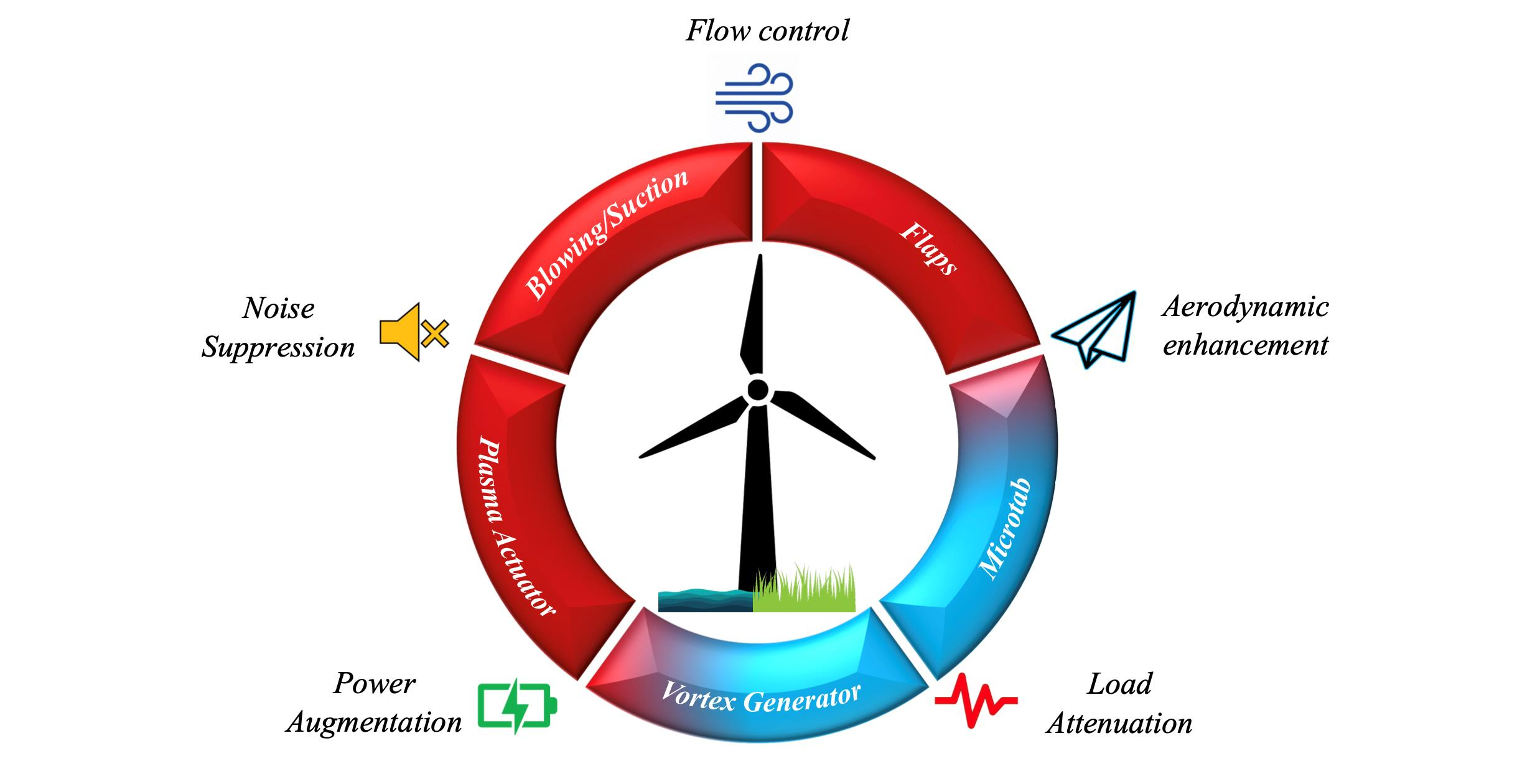
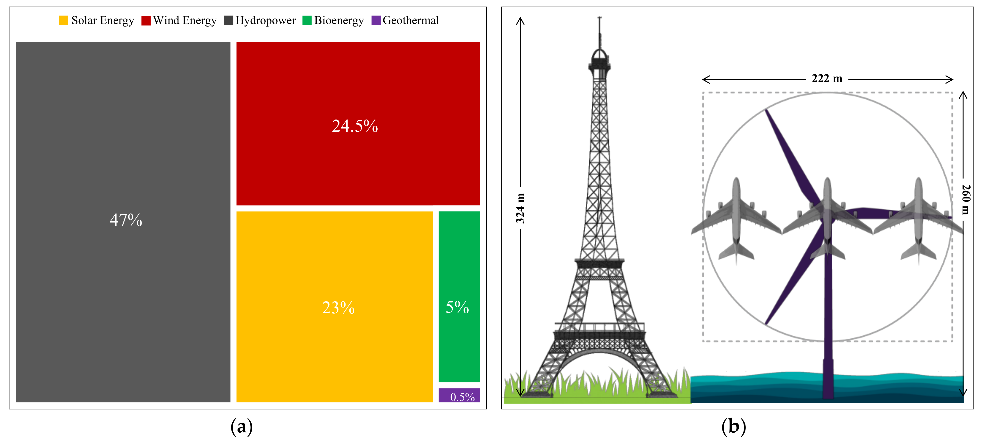
The last few decades were marked with a sharp depletion in global fossil-fuel reserves and a rise in environmental concerns. Consequently, the focus shifted toward eco-friendly and renewable sources for global energy security. The development and optimization of renewable energy sources, i.e., hydro, solar, wind, bioenergy, geothermal, etc., hold the key to achieving sustainable power production. According to the International Renewable Energy Agency (IRENA), the Global Renewable Energy (GRE) capacity at the end of 2019 amounted to 2537 GW, which is equivalent to 34.7% of the Net Global Energy (NGE) capacity [1], and this represents a growth of 7.4% (176 GW) from 2018, in which 2.5% was contributed by wind energy [1]. The share of various renewable energy sources in the GRE capacity is presented in Figure 1a, whereas the steady contribution of wind energy over the last decades is depicted in Figure 2. Accordingly, at the end of 2019, the Global Wind Energy Council (GWEC) reported an increase of 10% in the Global Wind Energy (GWE) capacity, which could be expected to maintain an average growth of 9.2% over the next five years [2]. Such a forecast in the growth of wind energy has been seen to be corresponded by the demand for larger turbines. The modern multi-MW wind turbines feature diametric size of more than 200 m with the projected power generation of up to 15 MW [3]. Some of the world’s most powerful wind turbines include General Electric’s Haliade-X (12–14 MW), Siemen Gamesa’s SG 14–222 DD (14–15 MW), etc. Figure 1b illustrates a comparison of the size of Boeing’s Airbus 380 and the Eiffel Tower with a state-of-the-art offshore wind turbine (SG 14–222 DD), exhibiting a rotor diameter of 222 m with a rated capacity of 14 MW, scheduled to be commissioned in 2024 by Siemens Gamesa [3].
Enlargement in the wind turbine size causes concerns in terms of the ultimate and fatigue loads experienced by the blades. For instance, these multi-MW wind turbine blades operate in the atmosphere several hundred meters above the ground, and they are more likely to experience increased turbulence, local gust-induced fluctuations, wind shear (horizontal and vertical), blade-tower interference, and yaw/tilt misalignment, among others. Moreover, the massive size of blade attracts gravity-induced periodic structural loads. These shortcomings can be compensated by a control mechanism of load alleviation and fluctuation damping to efficiently harness wind energy, while ensuring safety from blade operation. For one, achieving flow control around the blade enhances the aerodynamic and aeroacoustics performance of the blade while mitigating extreme and fatigue loads [4], and this could be done by advancing/delaying transition, enhancing/suppressing turbulence, and promoting/preventing separation. In total, two schemes mainly applied for flow control exist: passive and active. On one hand, the passive mechanism employs geometric shaping and grooving and fixed mechanical-structures, among others, to manipulate pressure gradients for enhanced aerodynamic response and flow control [5]. Conversely, active control employs sensors distributed along the blade profile to capture local variations in the flow conditions and the subsequent adverse blade loading. In both schemes, microprocessors are employed to process sensor-feedback and apply integrated control algorithms to command local actuators, enhancing the system response [6]. However, the fact that flow-control induced enhancements are not mutually exclusive is worth noting; therefore, the selection of flow-control devices may be case-specific to achieve performance goal with minimal tradeoffs.
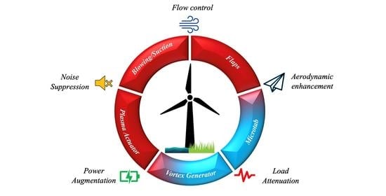
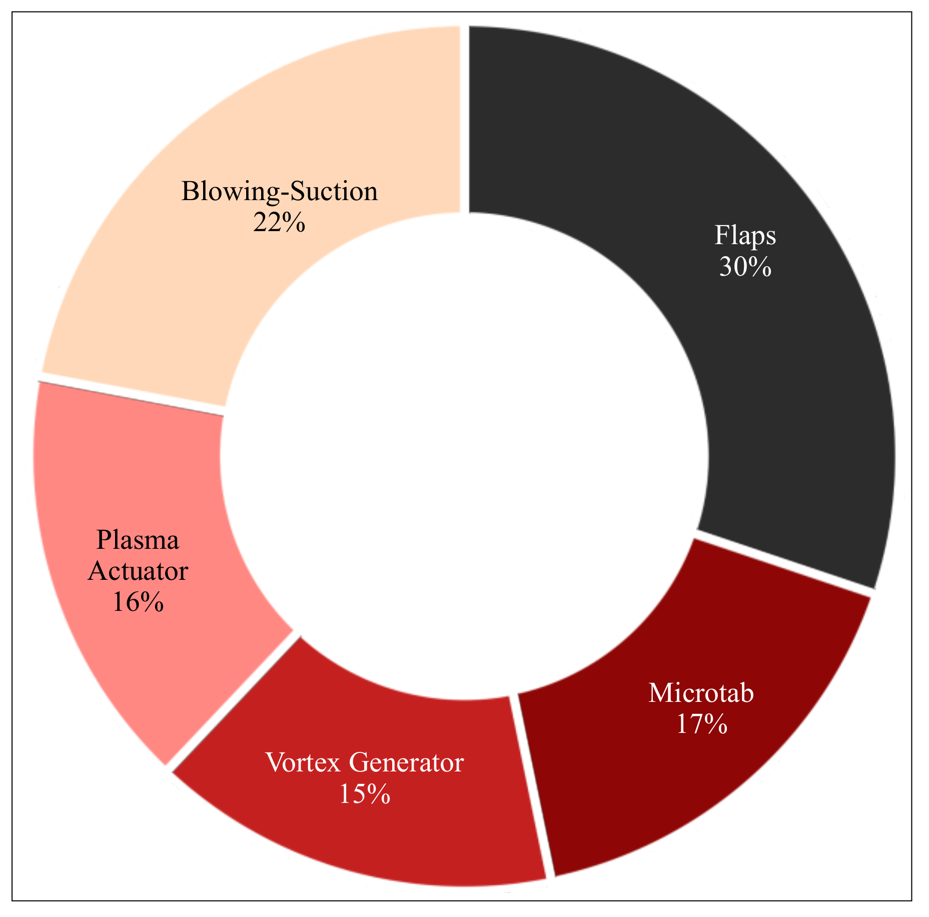
This article presents a state-of-the-art review of various flow-control devices used for wind turbine performance enhancement, such as flaps (rigid, flexible/ATEG,, and gurney), microtabs (tabs and trailing-edge effectors and MiTE), vortex generators (passive, smart, and micro vortex generators), plasma actuators, and blowing-suction mechanisms (steady and pulsed-blowing/suction, circulation control, and vortex generator jets). A summary of the share of the reviewed flow-control devices in the presented literature is given in Figure 3. The review presents a comprehensive and up-to-date progress in each flow-control device, along with detailed discussions of the associated prospects and challenges toward wind turbine applications.
It also includes a comparative analysis of the aerodynamic enhancement (lift controllability) potential and current state of these devices (Technology Readiness Level, TRL). The review ends with a summary of the main conclusions.
2. Performance Enhancement Devices
2.1. Flaps
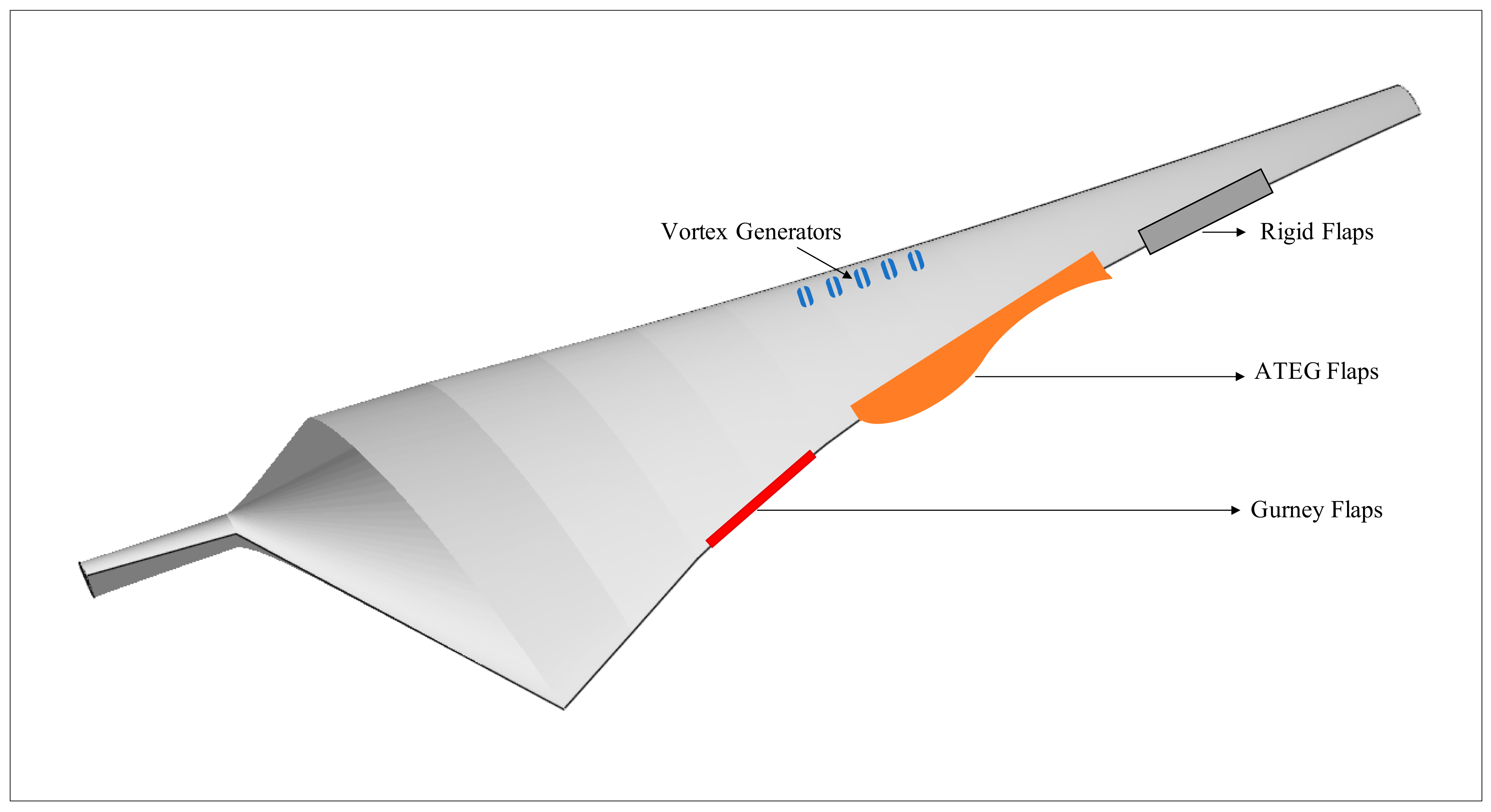
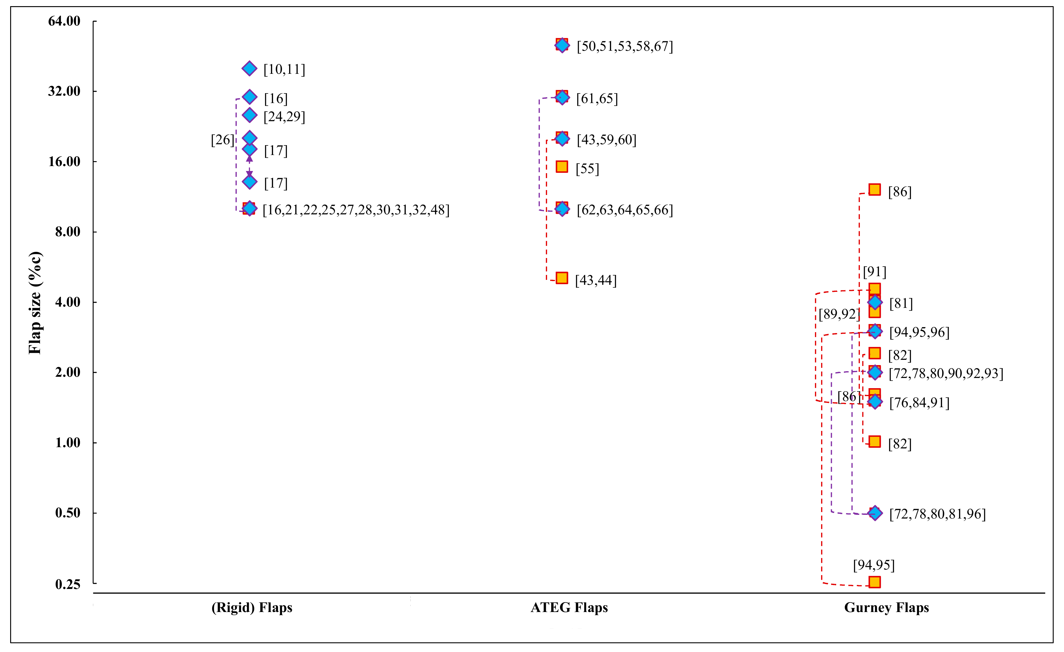
Flaps refer to the movable surfaces hinged on a blade/wing to tailor the aerodynamic performance by varying the aerofoil camber. These surfaces effectively enhance the lift by modifying the chordwise pressure distribution [7]. The idea of employing flaps dates back to the 1930s, and, since then, they were broadly employed in two variants based on the torsional stiffness of the blade/wing [8]. Flaps being mounted on torsionally stiff blades exhibit increments and decrements in the aerodynamic load, respectively, based on the deflection toward the pressure and suction-sides, whereas flaps being mounted on torsionally soft blades experience pitching moment and subsequent blade-twisting toward the flap-deflection side. An illustration of rigid flaps is presented in Figure 4. Figure 5 shows a plot of the literature survey of flap size as a function of chord length (%c).
As early as the 1990s, research on flap-based control systems for wind turbines aimed at achieving performance enhancement was initiated by the National Renewable Energy Laboratory (NREL). The studies centered around flap-assisted power regulation and aerodynamic braking [9,10,11] and delaying flow transition [12,13].
Flaps were employed in wind turbines primarily for load control. Stuart et al. numerically analyzed their effectiveness in alleviating blade load in wind turbines, demonstrating specifically their potential for load control and power augmentation [14,15]. Lee et al., 2014 [16] and Castaignet et al., 2014 [17] conducted similar investigations, reporting nearly 20–50% and 14% reductions in root load, respectively, whereas the potential of using segmented flaps for enhanced gust (local) and load control was detailed in [18,19,20].
Ng et al., 2014, 2016 [21,22] carried out extensive numerical studies on the dynamic load alleviation of flaps on the NREL 5-MW turbine, which successfully displayed corresponding reductions of 12 and 20% in blade-root bending moment and tip deflection. Reference [23] suggested harmonic pitch action targeting 1P load, which further enhanced the alleviation to 23 and 36% in root-bending moment and fatigue, respectively. Moreover, a synergy of individual pitch control with active flap deflection for load control [24] alleviated loads not only on the blade, but also on the rotor hub and tower. Further, novel flap-control concepts/strategies of employing local inflow-condition feedback [25] and sinusoidal flap deflection [26] also enhanced the load alleviation.
Flaps potentially effective in power augmentation [27], in the reduction in the levelized cost of energy (LCOE) [28], and load alleviation (after optimization), while maintaining steady power generation [29]. In the studies cited, root-bending moment (power spectral density) was reduced by 87% to 97% at 1P frequency, where the average decrement in power (standard deviation) ranged from 8 to 42%.
Flap mechanisms introduced as of late employ passive activation. These include an inertial-driven flap [30] and a mechanical-driven one comprising springs, dampers, and inverters that collectively sense the angular velocity of the flap to generate actuation torque [31]. These mechanisms were shown to be effective in the significant suppression of load and tip and tower-top (fore-aft) deflection.
2.1.1. Adaptive Trailing Edge Geometry (ATEG)
An efficient camber control by smooth deformation of the aft-portion of the aerofoil generates an adaptive trailing edge geometry (ATEG) [32], and this concept modifies the Kutta condition for airfoil flow and circulation by morphing the camberline, which enhances the lift and aerodynamic efficiency, particularly in off-design operation conditions [33]. ATEG concept is illustrated in Figure 4. Next, several ATEG concepts were developed and tested extensively over the years, including the multi-link design mechanism (DLR) [34], belt-rib concept (DLR and others) [35,36], mechanical/hydraulic concept (SAAB) [37], serrated rib mechanism (Boeing) [38], SMA-based system (DARPA/AFRL/NASA/NGC) [39,40], and piezoelectric actuated system (RISØ and TU Delft) [41,42].
ATEGs research aim to tailor the aerodynamic response of wind turbines under steady and dynamic operations [43,44]. Based on experimental investigations, these mechanisms yield 0.1–0.13 ΔCL-increment and 80% ΔCL fluctuation-reduction, under static and dynamic operations, respectively [44].
Two-dimensional (2D) unsteady-aerodynamic numerical analyses of ATEG-equipped aerofoils were modeled after various potential flow analytical methods [45,46] and analytical expressions [47]. For example, several studies were performed to enhance the aeroelastic response of flaps by load-control optimization [32,48,49]. A 2D aeroelastic model of the ATEG-equipped airfoil was developed and validated to gain insight of the aerodynamic load reductions [32]. The model was analyzed using a proportional-derivative (PD) controller to actively deflect the trailing edge geometry of the airfoil. The load attenuation was computed by acquiring the displacement fluctuations of the airfoil. Likewise, a 2D aeroservoelastic system, coupling the aerodynamic and elastic models was investigated [48]. It was simulated by suspending a 2D airfoil equipped with 10% adaptive trailing edge, using spring-damper system. Consequently, ATEG-equipped 2D aerofoils were reported to gain up to 80 and 95% reduction in normal-force excursion when subjected to steady and turbulent-flow conditions, respectively [48]. Similar aeroelastic model has also been applied on the wind turbine blades using PD control strategy for flapwise deformation [49]. A significant reduction of 60% in the flapwise blade-root moment was achieved with tests on the Vestas-V66 wind turbine [49]. Moreover, Hulskamp et al. [50,51] experimentally demonstrated reductions of 60 to 95% in the blade-root strains.
ATEG application on smart rotors is aimed at load alleviation [52,53] and stall control [54,55]. Several aeroelastic codes were developed for active load control on MW-scale turbines [56,57,58]. Indeed, the load-control effectiveness of ATEGs on wind turbines were reflected in numerous studies [59,60,61,62,63,64,65,66,67].
Comparatively speaking, ATEGs are superior to conventional flaps [59,60], as it requires 30% less of the deflection required to achieve equal lift enhancements. Parametric studies of ATEGs for unsteady and fatigue-load control [61,62] suggest that the decrement in the fatigue load could be attributed to alteration in the flow-blade interactions changing from in-phase to anti-phase at the main load frequencies, thereby damping the interactions and attenuating fatigue loads [62]. Vortex shedding from the deflected ATEG-flap was observed to be detrimental for load control, for instance, the 3D flow effects on a 10-MW wind turbine exhibited 35% deterioration in performance due to vorticity [65].
Accordingly, the introduction of ATEGs on the NREL 5-MW reference turbine resulted in 13% reduction in blade-root bending moment, accompanied by reductions of 15 to 24% in the standard deviation [63]. Reference [64] reported similar results, with the reduction range of 5–15% in the other wind turbine components-shaft, nacelle, and tower. Furthermore, the application of ATEGs on a floating NREL 5-MW turbine led to the successful suppression of the fluctuating load or relative motion of critical components by 25–40% (standard deviation) [66].
2.1.2. Gurney Flaps
Gurney flaps are flat plates mounted perpendicular to the profile on either side of the trailing edge, mainly for performance enhancement and load alleviation, as shown in Figure 4. These plates are named after Dan Gurney, who documented its principle in late 1970s [68]. The working principle involves formation of counterrotating wake vortices that energizes the boundary layer and mitigates flow separation. Next, separation-delay shifts the stagnation point downstream of the trailing edge, thereby enhancing the lift performance of the aerofoil [69]. The optimal size of gurney flaps ranges from 0.5 to 2.0% of the chord length, which is comparable to the (local) boundary-layer thickness, to ensure minimal drag penalty [70]. Gurney flaps are also practically used in active flow-control devices, thus the term microflaps [71].
Gurney flaps were initially applied in the 1970s as flow-control devices in aerodynamic analyses [70]. Practically, they modify air circulation by pronouncing a flow curvature at the trailing edge that augments the lift. Enhancement of lift, with respect to flow curvature, was quantified [72,73,74,75], numerically simulated [76], and experimentally verified [77].
Synthesis of gurney flap and vortex generator controls was also explored to exhibit significant aerodynamic enhancement [73,78]. Flow-control effectiveness of gurney flaps under static and dynamic loadings exhibited significant improvements in coefficients for lift and pitching moment, for both stalled and un-stalled cases [79].
Maughmer and Bramesfeld [80] explored the influence of size and location on the flow-control effectiveness of gurney flaps. Here they observed that the lift enhancement is linearly dependent on the chordwise location and the sizing of flap, which were further complemented by the findings in [81]. Moreover, the influence of aerofoil profile on the effectiveness of gurney flaps was asserted in [82].
Following the results in [83], the scope of serrated and slit gurney flaps was determined in [84,85] aimed at curtailing vibration and noise arising from the solid tab vorticity. The aerodynamic and wake-flow analysis of perforated gurney flaps exhibited an enhanced glide ratio due to uneven deterioration in the aerodynamic loads [86].
As mentioned earlier, gurney flaps are also essential for load alleviation. Active flow control using gurney flaps can demonstrate 70% reduction in dynamic lift [87] and blade load alleviation of up to 35.8% [88]. An extensive study of the influence of active flow control on aerodynamic loading and its dependency on wake-vorticity [89] recommended finite flap deployment for reduced load excursions, which was further established by simulating active gurney flaps on a 5-MW NREL wind turbine [90].
Suggestive explorations of the potential of gurney flaps for power control showed successful improvements in startup performance [90], and power output and efficiency maximization [91]. Gurney flaps applications in diffuser-augmented wind turbines and in the NREL 5-MW turbine enhanced the power coefficient [92] and output power [93], respectively. In addition, parametric investigations for the optimal sizing and positioning of gurney flaps occurred to achieve enhanced aerodynamic performance [94,95], with the numerical analysis [94] on an S810 aerofoil exhibiting up to 70% increment in the glide ratio. Recently, the multi-layer perceptron back-propagation (MLP-BP) was employed to determine the flap sizing for the maximum glide ratio to optimize power output and turbine efficiency [96].
2.2. Microtabs
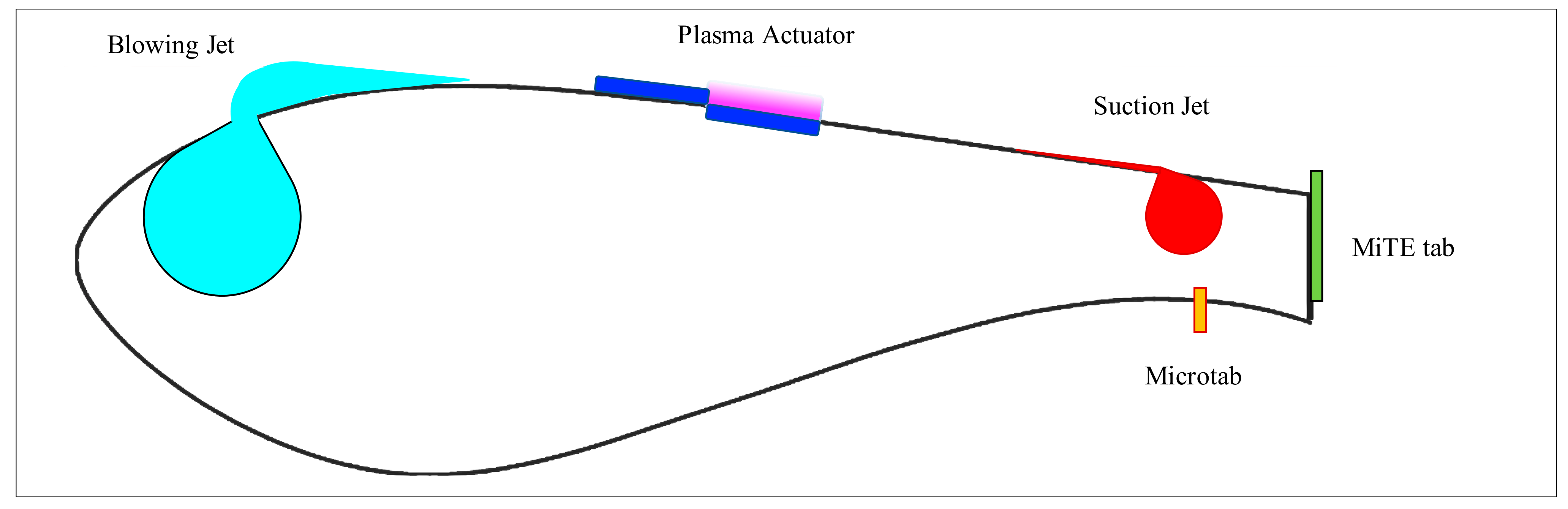
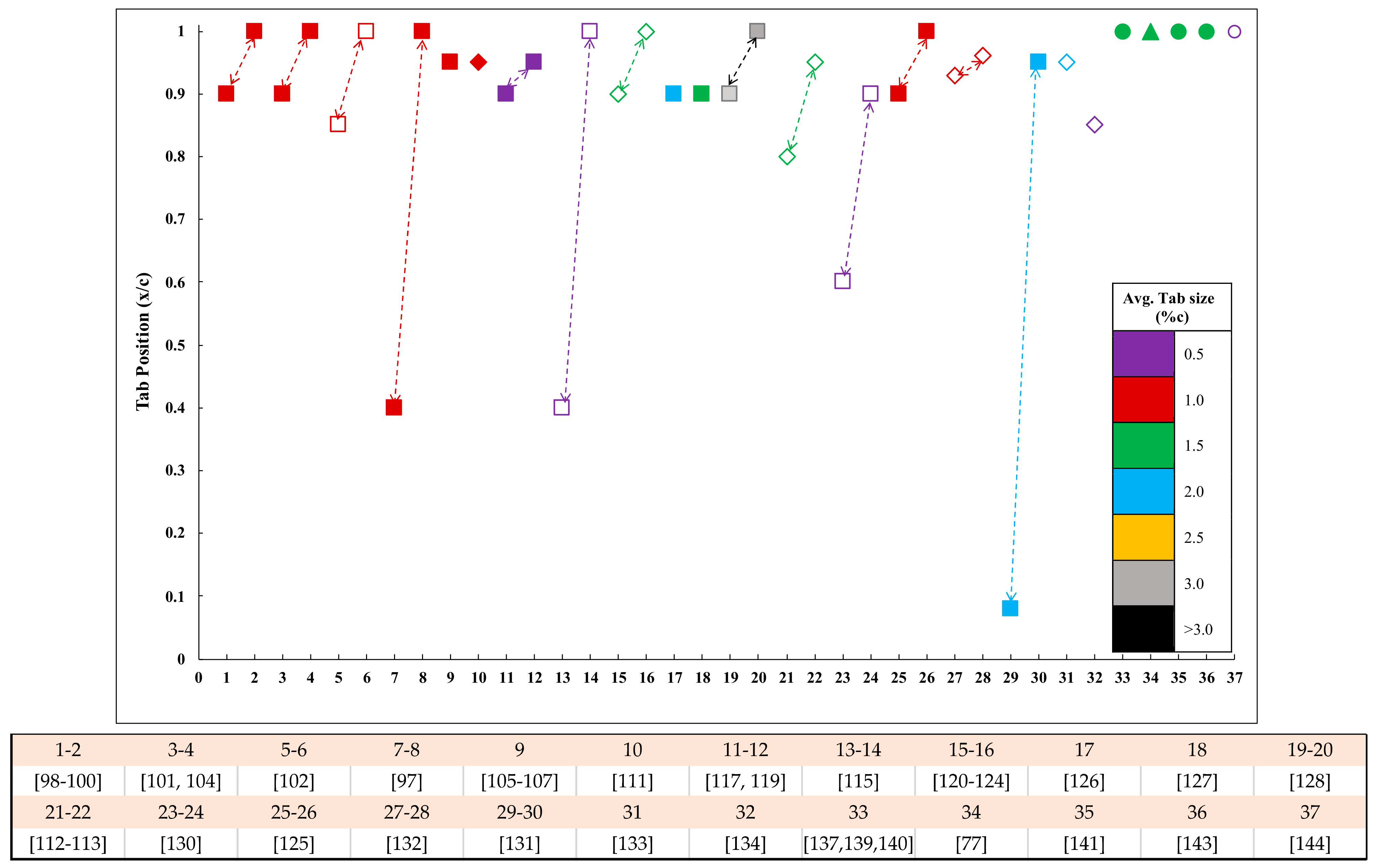
Microtabs are small translational tabs deployed approximately perpendicular to the profile, slightly upstream of the trailing edge on either side of the aerofoil/blade. The microtab height is usually 1–2% of the chord length, comparable to the boundary-layer thickness, as illustrated in Figure 6. The microtab deployment modifies the trailing edge circulation (Kutta condition) by effectively altering the camber, thereby shifting the stagnation point [69]. By capturing the streamline, deployment on the pressure side enhances lift, thus, leaving the suction side into a recirculation zone in the tab-wake [84]. ∆CL enhancements of up to 0.5 were achieved under moderate angle of attack (AOA), characterized by attached flow conditions [97]. Alternatively, deployment of a microtab on the suction side promotes lift mitigation. Lift reduction is further obtained by placing microtabs in the vicinity of pressure-recovery onset, thereby inducing flow separation. Microtabs may be designed as modular assemblies of the micro-electro-mechanical (MEM) tabs comprising micro dovetail slider-joints actuated by integrated electronic circuits. The literature survey of the microtabs as a function of the chordwise position (x/c) is shown in Figure 7.
Microtabs as aerodynamic devices was initially proposed by van Dam [98]. The earliest studies focused at load enhancements, which successfully demonstrated up to 50% increment in CL [99]. Next, further studies concentrated on the load enhancement performance of active microtabs by spanwise array actuation [100].
Subsequently, a large number of studies hinted the potential of applying microtabs for load control. To verify this experimentally, the tabs were installed on both sides of the trailing edge [97,101,102]. A parametric analysis on the optimal sizing and positioning of microtabs reported that suction-surface tabs effectively alleviated loads only in the linear-lift region, and eventually, they became ineffective over high AOAs [103].
Also, the relationship between a microtab-gap and load control was investigated using 3D computational modeling [104], the results of which suggested that the tab-gap could be detrimental to load enhancement because of the global-pressure alteration triggered by the flow passage. Nevertheless, tab-gaps were shown to significantly improve the glide ratio.
The dynamic behavior of microtabs during deployment and subsequent transient response of lift and drag was comprehensively examined in [105,106,107], describing that transient response is dictated by the tab-deployment speed, that is, a quicker deployment would generate a larger adverse-overshoot. However, the presence of minor transient effects during the experiment was observed to have promoted the microtabs actuation as “on/off” devices. Subsequently, this investigation was pursued on wind turbines using 3D simulations [108,109]. Based on the results, the rapid deployment of microtabs averted any noticeable effects on the blade, because of the shorter adverse-lift response time compared to the structural response time. Additionally, the results highlighted the negligible effect of microtab dynamic response on the load-control potential.
In the case of the analysis of blade loading under the influence of microtab [110], its deployment on the NREL controls advanced research turbine (CART) emphasized an increase in the blade-root bending moment with noticeable increment in blade loads and deflections. This finding was applied for profiling the tabs, resulting in up to 70% reduction in the peak root-bending moments and reduced tip deflections [111]. For aeroelastic control and blade loading, the dynamic performance of microtabs are detailed in [112,113]. Specifically, these studies showed the highly effective load alleviation potential of active microtabs.
In the aeroacoustics studies on wind turbines equipped with microtabs [114,115], the microtabs were identified to be a source of noise, further amplified under gapped-configuration [114]. Porous microtabs were recommended for noise mitigation while targeting the maximum glide ratio [115].
Investigations of the unsteady aerodynamics of microtabs can quantify the phase-lag between tab-deployment and the resulting aerodynamic response, due to vortex shedding [116]. This highlights the potential for tailoring sectional performance by applying a high-frequency deployment scheme. Further analyses of the aerodynamic response of microtabs on wind turbines under dynamic loading are described in [117,118,119], which reported their effective suppression of lift-excursions by up to 91%, whereas their sequential deployment is preferred for sectional lift-adjustments [119]. Moreover, regarding the influence of microtabs on wind turbine aeroelastic control [119,120], active microtabs were observed to be highly effective in unsteady load alleviation over a wide range of frequencies.
Microtabs on wind turbines can also aid in flutter control. For instance, an adaptive-control design based on the Beddoes-Leishman model successfully showed flutter suppression in open/closed loops [120,121,122]. Aside from flutter suppression, the divergence abilities of microtabs could be achieved with larger deployment and longer control time [123]. Furthermore, microtabs exhibit the potential for moderate and deep stall-flutter control [124]. Similar findings were reported in [125], with recommendation of increasing the tab-height and forward positioning to amplify the microtab effectiveness.
Finite-width microtabs were reported to be effective in enhancing aerodynamic performance [126,127,128]. For instance, the finite-tab system could be potentially employed for adaptable load control, based on designed tab height, aspect ratio, and solidity ratio [128].
The tab-height is a critical parameter in microtab performance, which is restricted by its linear actuation. A novel 4-bar linkage mechanism design in [129] was able to increase the tab-height by 70%, which subsequently enhanced the load-control performance.
Reference [130] details an analysis of the potential of microtabs for shock-oscillation suppression and buffet-load alleviation. In the results, the microtabs considerably limited the shock oscillating range and buffet-load fluctuation frequency, by reducing the shock traversing speed and altering the wake-flow velocity behavior.
Microtabs mounted close to the trailing edge become ineffective near stall angles as they get drowned in the separated flow. The load-control effectiveness of microtabs mounted in the fore and mid sections, explored in [131], demonstrate superb load alleviation at both locations, with a slight increment in unsteady forces in the fore section.
The potential of microtabs for power augmentation was explored in [132,133,134]. Accordingly, power enhancement went to as high as 12.5% [133], while the increment in power coefficient was approximately 21% [134]. The tab height was found to promote thrust but deteriorative for output power (by protrusion off the boundary layer) [134].
Located at the trailing edge of the aerofoil/blade are miniature trailing-edge effectors (MiTE), which are mini translational flaps whose size varies from 1 to 5% c (chord length), as shown in Figure 6. Specifically, they are installed on blunt trailing-edge aerofoils and are deployed in three positions: up, down, or neutral (retracted). These control devices aid flow detachment upstream their position and shed a pair of counterrotating vortices downstream, thereby modifying the trailing-edge Kutta condition. In particular, upward deployment of MiTEs results in lift reduction, while downward deployment enhances the lift response.
MiTEs as active load-control devices were first realized in 1998 at the Stanford University [135]. Later, in 2008, a patent was awarded to Lee, Bieniawski, and Kroo for their MiTEs concept [136]. Lee and Kroo extensively studied the load-control effectiveness and aerodynamic response of MiTEs [137,138,139], mainly exhibiting effective flutter suppression [137] and load-control potential [138], while the accompanying steady and unsteady aerodynamics investigations indicated that the lift coefficient increases with the MiTE height [139].
A particle image velocimetry (PIV) analysis on the wake physics of MiTEs [77] allowed the visualization of two vortex-shedding modes constituting the von Kármán vortex street and the intermittent tip-vortex shedding (downstream and upstream of the tab). Besides camber-increment, lift enhancement was attributed to the interaction between the shedding modes. The secondary shedding improved fluid circulation and subsequent lift, by inducing a net-negative velocity on the wake structure. These findings were complemented by [140], who associated the shedding frequencies and amplitudes to the net trailing-edge thickness.
2.3. Vortex Generators
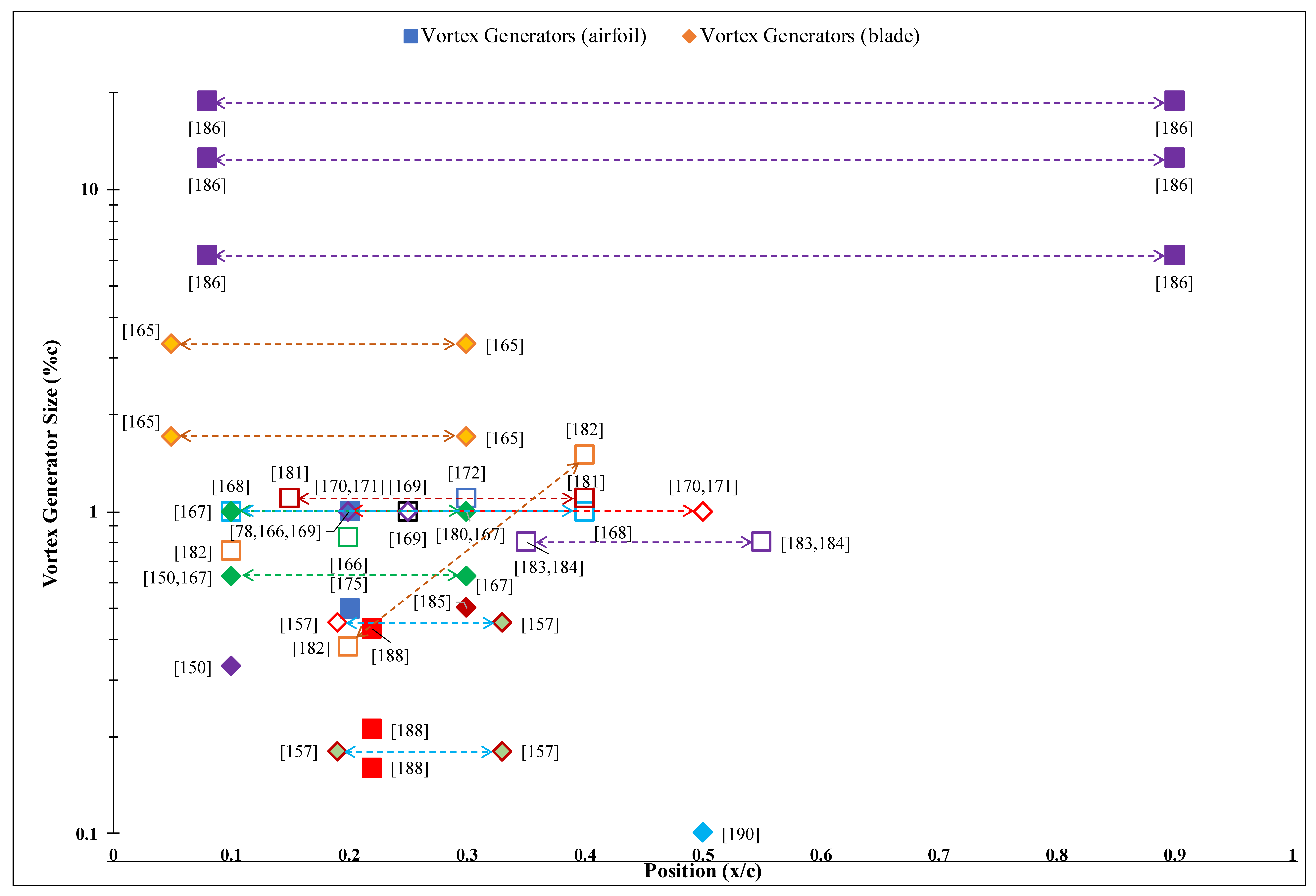
Vortex generators (VG) are usually triangular or rectangular small vanes mounted on the suction-surface incident to the incoming flow. By carrying momentum from the free stream into the inner-flow zone, VGs generate trailing vortices that essentially modify fluid-movement and reenergize the boundary layer, which delay flow separation and enhance the overall lift coefficient [145]. Separation of the boundary layer occurs when the section nearest the wall or leading-edge witnesses flow reversal. Under stall conditions, the separation point is characterized by null/negligible shear stress. The vortices produced by VGs were experimentally observed to possess helical symmetry [146]. VGs are installed as co-rotating and counterrotating arrays to exploit their natural alignment by promoting fluid-entrainment into the boundary layer from the free stream and profile-surface, respectively. An array of VG is illustrated in Figure 4. The counterrotating VGs are more efficient as they advect comparatively higher-momentum fluid into the boundary layer, thereby strengthening the surface flow and making it more resistant to the adverse pressure gradient [147]. Figure 8 displays a plot of the literature survey of vortex generators as a function of size (%c) and position (x/c), relative to the chord.
Next, in the late 1940s, the development of VGs was initiated by Taylor [148,149]. Their application on wind turbines was first set out in the early 1980s, which resulted in an increment of 20% in the Annual Energy Production (AEP) of Mod-2 [150,151] and Mod-0 [152] wind turbines. Subjected to under-rated conditions, an increment of 15.2% in AEP was attained for a 2.5-MW (Mod-2) wind turbine [150]. Another study on an Elkraft wind turbine subject revealed an increase in the maximum power output from 800 kW to nearly 1 MW [153].
A good demonstration of VGs applied in flow control can be found in Lin et al. [145,154,155,156,157], which highlighted the application of miniature VGs for separation control. Although these micro VGs exhibited a fraction of the boundary-layer height, they were equally effective in turbulent-flow conditions. A detailed description of these micro VGs is presented in the next sections. The effect of VGs on the aerodynamic performance of various aerofoils was reported in [75,158]; aerofoils mounted with VGs showed significant enhancements in lift coefficient (CL,max). Further, the interaction of streamwise VG vortices with the crosswise dynamic-stall vortex (DSV) [159] revealed that under dynamic-stall operations, VGs restrain the negative pitching moment to curtail the net drag force and mitigate flow separation.
Because of the miniature size of VGs, when conducting a numerical analysis, a very detailed mesh profiling is essential. Nevertheless, the alternative approach is to model their influence on the boundary layers by considering the generated body forces and boundary-conditions. The BAY model was introduced by Bender et al. [160] to simulate the vane vortex generators. Further developed by the application of the lifting force theory, it was renamed into the jBAY model by Jirasek [161]. A detailed comparative study of VG models, i.e., traditional meshed-VG, AcVG (based on [160]), experimental ([162]), and analytical-modeling of the primary vortex, is presented in [163]. Eventually, the AcVG model was validated and recommended for its practicality in terms of the computational effort and time.
Also, numerous investigations occurred on the application of VGs for aerodynamic performance enhancement. In [78], a 25% increment in lift coefficient (CLmax) was achieved for a stall delay of 6°. Moreover, counterrotating VGs demonstrated superior aerodynamic performance over the co-rotating ones under post-stall conditions [164]. A detailed parametric study on VGs recommended that an optimal adjacent-spacing of 5H (VG height) and a positioning of x/c = 0.15–0.2 enhance the aerodynamic response and post-stall lift behavior, respectively [165]. In terms of size, smaller VGs were observed to outperform their larger counterparts, which is consistent to the findings for a study on the VG-equipped DU97-W-300 blunt trailing-edge aerofoil [166]. Particularly, the drag showed more sensitivity to VG height than the lift, leading to a decrement in the glide ratio with the size-increment. This research was extended by performing parametric investigations on different wind turbine aerofoils [167], using double-row VGs for lift increments at large AOAs, subject to careful sizing and positioning. The superior aerodynamic response of double-row VGs was further demonstrated with comparatively severe boundary-layer suppression and greater stall delays using an S809 aerofoil [168].
Several studies exist investigating the potential of VGs for power augmentation of wind turbines. For instance, researchers found that the power-output increment on a VG-equipped DTU 10-MW turbine in the presence of blade surface roughness could go as high as 10% [169], although such an augmentation was nearly negligible for a turbine with clean blades [170]. This research was extended to the study of the radial dependance of VGs for the desired turbine performance, which concluded that they may be detrimental on the lift increment at high AOAs due to 3D effects [171]. Meanwhile, the practicality of VGs for blade soiling mitigation on wind turbines was explored in [172]. Here, the presence of VGs on the NREL 5-MW turbine mitigated separation and blade soiling, thereby enhancing the AEP from a 6.6% loss to a 1% gain. Moreover, along with a gurney flap, VGs could exhibit overall power generation increments of up to 10.5% on a 5-MW wind turbine [93]. A joint academic-industry study was recently conducted to assess the efficient methods for estimating and quantifying the impact of vortex generators on wind turbine power generation [173].
To gain insights into the wake structure of VGs and its effects, wake visualization using PIV [174,175] and a study of wake evolution [176] were conducted. The wake physics was particularly investigated for CFD modeling and validation using the experimental results [177]. Reference [178] centered on the primary characteristics of the vortex, including its formation, sizing, and trajectory. Eventually, a prediction formula was devised to represent the evolution of vortex size in the wake of VGs. To elucidate the vortex evolution, the wake physics of the primary vortex was recently simulated by performing parametric analysis employing the spanwise velocity, normalized vorticity, and turbulence kinetic energy fields in the VG wake [179].
Accordingly, abundant research exists detailing the effectiveness of VGs for separation control and stall suppression. Experimentally, the NTUA-t18 aerofoil exhibited significant stall delays (up to 5°) and lift enhancements (up to 44%) with negligible drag increment (0.002) in the pre-stall regime [180], which was supported by [181] with recommendations for double-row VGs. Specifically, double-row VGs were shown to successfully eliminate flow separation by accelerating the near-wall flow and overcoming adverse pressure gradient; thus, they are highly effective for dynamic-stall control and separation control on a pitching aerofoil [181,182].
A novel rod vortex generator (RVG) was proposed by Suarez et al., 2016 [183] for separation control. A feasibility analysis performed on S809 aerofoil exhibited 11% increment in glide ratio and separation suppression till the AOA of 12.2°, and these RVGs were further installed on an NREL phase-VI rotor exhibiting 0.54 and 0.67% increments in torque and thrust values, respectively [184]. Meanwhile, aerodynamic-VGs based on CLARK-Y aerofoil (11.7% thickness) [185] demonstrated an increment of nearly 4% in the glide ratio (max) with the potential for up to 25% enhancement in the performance with variations in the flow incident angle (β).
2.3.1. Smart Vortex Generators (VGs)
By enabling active flow control, smart VGs could tailor lift enhancement and stall delay in real-time [186]. They were experimentally demonstrated to produce an increment of 0.16 in the lift coefficient and a stall delay of 1.8° [186]. The adjustable height of Smart VGs enhances the glide ratio by 42% with negligible (0.1%) drag-amplification, under post-stall regime [186]. Further, they may be favored for un-stalling aerofoils with their activation under post-stall conditions [186].
2.3.2. Miniature Vortex Generators (MVGs)
Miniature VGs (10–50%) of the boundary layer, also referred to as micro vortex generators (MVG), can effectively delay separation under certain flow conditions, especially at low speeds [145]. The primary advantage of MVGs is the reduced parasitic drag associated to their tiny size. However, the vortices they generate are comparatively weaker, and therefore, they need to be strategically placed to generate the desired response. Earliest studies involving MVGs were aimed at evaluating separation-control effectiveness [187]. Experimental evaluations involving different orientations and sizes of VGs and MVGs demonstrated the latter’s capability to mitigate flow separation by up to 90% [157].
Various low-Reynolds-number (Re < 106) aerofoils are characterized by a separation bubble in the pre-stall region. This bubble is witnessed in the vicinity (downstream) of the maximum suction pressure point [145] and triggers separation, which creates an unstable shear layer and drastically affects drag. The experimental studies in [188], performed to eliminate the separation bubbles using VGs and MVGs [188], demonstrated the superior drag-reduction capability of MVGs at 38%, against 30% in the case of VGs.
Next, a comparative study of MVGs with varying height and aspect ratios being qualitatively and quantitively analyzed considering the vortex parameters, i.e., trajectory, peak vorticity, and streamwise boundary-layer profiles, is presented in [179]. The vortex trajectory paths for all MVGs were laterally coincident but vertically farther for bigger MVGs. Moreover, the bigger MVGs shed larger primary vortex and greater wall shear stress in the wake, thereby transferring greater energy leading to enhanced stall delay and separation control.
2.3.3. High-Frequency Micro Vortex Generators (HiMVGs)
Similar to smart VGs, high-frequency micro vortex generators (HiMVG) oscillate at high frequencies to produce periodic vortices. The pioneering research on HiMVGs focused fundamentally on flow-separation control [189]. Osborn et al. [190] investigated the separation control potential of HiMVGs over flaps under turbulent-flow conditions. The results showed that that unlike traditional VGs, HiMVGs mitigate flow separation with their dynamic deployment being more effective than static operation.
2.4. Plasma Actuators
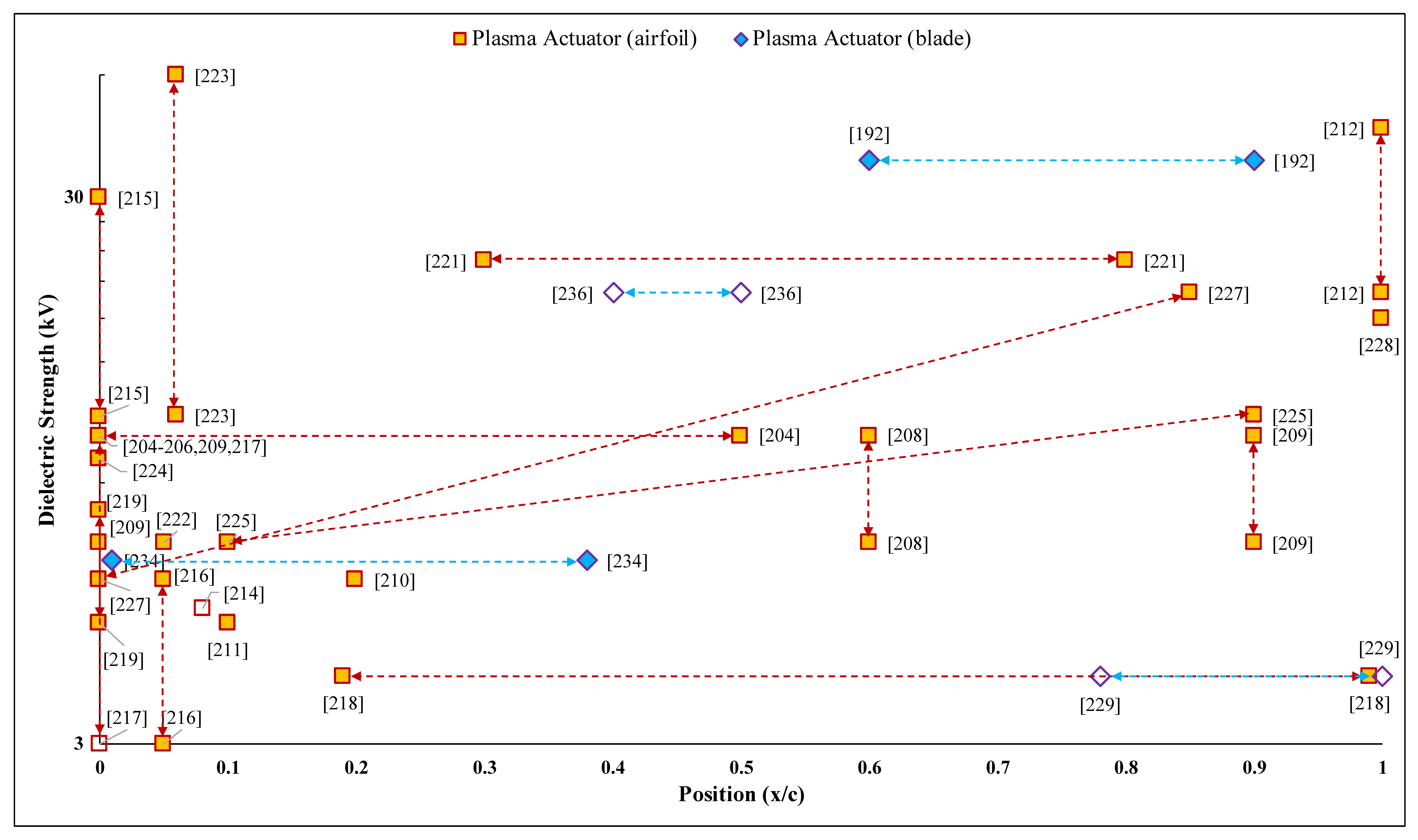
Plasma actuators consist of two electrodes, anode and cathode, wired at large voltage-difference to generate electric field and induce “plasma-wind” near the surface, as shown in Figure 6. The “wind” is generated by the impact forces in the electrode gap area of collisive plasma ions and neutral particles (air) [191]. Accordingly, the induced wind acts as a body force and pushes the surrounding fluid, thereby generating the zero-net mass flux (ZNMF) jet, which modifies the airflow profile on the boundary layer and postpone the separation. The plasma-induced jet adds momentum to the boundary layer, and thus, it results in flow instabilities that alter the boundary-layer properties [85,192,193,194]. The actuator’s performance depends on geometrical (electrode shape and thickness, distance gaps, etc.) and electrical parameters (voltage, shape of wave and frequency while AC, etc.), ambient air characteristics (temperature, heat, humidity, wind velocity, etc.), and the dielectric surface design [191,195,196,197]. Plasma actuators are designed with various configurations, some of the primary ones include devices with DC surface corona discharge, AC surface dielectric barrier discharge, sliding discharge, and wall jet [85,191,193,198]. Figure 9 shows a plot of the literature survey of plasma actuators with the dielectric strength (kV) as a function of the chordwise position (x/c).
Plasma actuators were initially developed by Velkoff and Ketchman [199] in the late 1960s, while their application as flow-control devices was first investigated in the 1990s [200,201,202]. Over the years, numerous investigations concerning flow-separation control and aerodynamic enhancement using plasma actuation surfaced [203,204,205,206,207,208,209,210,211,212,213,214,215,216,217,218]. The actuation was reportedly comparable to a minor camber-increment effect, which exhibits increments in aerodynamic forces [203], whereas an aerodynamic analysis of which demonstrated glide-ratio enhancement of 400% and stall delay of 8° [204,205,206]. The effect of unsteady plasma actuation on aerodynamic characteristics is shown in [208], revealing that actuation is comparable to flap-enhancements, without the demerits of form-drag and reduced actuation-power requirement of 10%. The above analyses were extended to actuator-arrays generating a jet-wall effect that induced glide-ratio enhancements of up to 340% [209]. With regards to the influence of actuation symmetry and arrangement [210], up to 67% augmentation in lift coefficient and 63% drag-coefficient reduction were observed with symmetrical actuation, thus delivering better flow control, while streamwise actuation was stressed to be superior to spanwise actuation. These results were backed by a comparative study between micro straight and curved-type plasma actuators [211], in which the superior flow controllability of curved-actuator was attributed to the formation of streamwise vortices. As demonstrated in [212], plasma-actuation-aided circulation control successfully augments the lift coefficient by 0.1 [212], where flow controllability was observed to subside over stall-approach and increment in stream velocity. Thus, unsteady actuation was recommended for enhanced circulation control and load alleviation on wind turbine blades. Plasma actuation on a pitching aerofoil [213] enhanced aerodynamic performance in the dynamic flow field during pitch-up at high AOAs, where the lift enhancement was accredited to the vortex-induced flow entrainment into the boundary-layer preventing separation, and this result was consistent with that reported for the dynamic-stall control [214,219], with corresponding lift-coefficient enhancement (7.1%), stall delay (1.3°), and reductions in hysteresis-loop region (4.5%) and drag-coefficient (44.5%) [214]. An alternating-current (AC) DBD actuator [215], employed in steady and unsteady AC plasma actuations, led to an average CLmax augmentation of up to 120%, with 5° stall delay. Meanwhile, flow control under burst-mode plasma actuation aimed at exploring the optimal burst-frequency for separation suppression [216] revealed that flow controllability is established at light and deep stall angles by the turbulent transition produced by high-burst frequencies (F+ = 6–10) and shear-layer vortex shedding, respectively.
Burst actuation was found effective in controlling stall hysteresis [217], where flow and sectional-lift control could be achieved within the hysteresis region with short actuation-bursts. Accordingly, plasma excitation on flow control using single and dual excitation modes [218] could result to 37 and 127% enhancements in lift coefficient and glide ratio, respectively. Note that in the latter study, all the actuator excitation modes obviously influenced the shear-layer instabilities and wake structures. Besides weakening the trailing edge vortices, the excitations also successfully broke down the upper-surface shear layer.
The optimal positioning of plasma actuators could be achieved ideally at the flow-separation point [197,220], in agreement with [221], at a note that being a function of angle of attack and Reynolds number, the separation point is subject to migration.
Asada et al., 2015 [222] investigated the transient effects arising from plasma actuation, revealing three distinct stages of the flow-physics: (a) flow entrainment into the boundary layer and shear-layer reattachment (aided by spanwise vortices), (b) lift augmentation, and (c) eventual bleeding of the spanwise vortices by fine 3D-vortices to enhance local flow control.
The option of applying a periodic-pulsed nanosecond DBD plasma actuator for flow control is described in [223]. Here, the DBD actuator generates thermal shock by executing rapid energy transfer to the boundary layer, accompanied by heating (nearly 8K/nanosecond). This is followed by pulse-periodic vortices that reenergize the boundary layer and suppress separation, in addition to significantly improving the aerodynamic and aeroacoustics performance. The wake-physics analysis of this actuator revealed similar phenomena, indicating a series of quasi-planar and spherical compression waves, followed by spanwise vortices in the post-stall regime [224]. Moreover, the flow controllability of a nanosecond discharge plasma actuator (NDPA) [225] could be described with impressive aerodynamic enhancements of stall delay (6°), lift augmentation (30%), and drag reduction (22%), which make it superior over micro discharge actuators, as signified by the supremacy of the remarkable shock-effect over the momentum-effect. Additionally, NDPA is effective for dynamic-stall control [226], with steady lift and moment growth accompanying flow reattachment at high Strouhal number (Ste > 2) excitation. In particular, at high excitations, the dynamic-stall vortex is weakened by the bleeding of the leading-edge vortices, due to the induced large-scale structures, and then eventually suppressed at Ste ≈ 10.
For load-control applications, actuation-arrays in various combinations exhibited load controllability over low free-stream velocities [227]. In addition, such load alleviation was attempted through circulation control using multiple-DBD actuators on a wind turbine blade [228], which showed effective load tailoring based on the jet flow direction. Nevertheless, micro-DBD plasma actuators were found effective in load alleviation and stability control [229], where a combination of actuators excited in different modes successfully mitigated aerodynamic load and improved flow stability, thereby alleviating blade fatigue and enhancing aeroelasticity.
Vortex-shedding suppression is among the unique applications of plasma actuators. In [230], effective vortex-suppression from blunt trailing edge demonstrated energy reductions (by a factor of 6) in the shed Von-Kármán modes. Alternatively, plasma actuators can act as vortex generators. DBD actuators were found to produce comparatively stronger vortices than vane-type VGs, to effectively control the rotating stall of a wind turbine [231]. Furthermore, plasma actuators were also shown to be practical in anti/deicing operations on wind turbine blades [232].
In the perspective of using plasma actuation for enhancement of wind turbine performance, the revolution-averaged torque can be augmented by 11–14% [233]. For stall control and power augmentation in off-rated conditions [234], plasma actuation can effectively mitigate the rotating stall by countering Coriolis-induced radial flow and aiding quasi-2D flow reattachment over outboard blade section, which yields to 22% torque-reduction (due to drag) and stall suppression. A field test on a 1.75-MW turbine [235] indicated that actuators can effectively suppress flow separation, resulting in the power augmentation of nearly 5% and expansion of operational wind envelope. For power augmentation under-rated wind conditions, such as that for a 5-MW offshore wind turbine [236], a rotor power enhancement of up to 0.85% was achieved, with a recommendation for actuator-placement in the inboard blade-region to maximize the aerodynamic forces, rotor torque, and power. Furthermore, a theoretical modeling of wind turbine regulation in off-rated conditions using plasma actuation can yield up to 25% enhancement [237], the regulating effect of which was validated by experimental investigations performed at NREL (Denver).
2.5. Blowing-Suction Control
The mechanism of blowing and suction-flow control relates to re-energizing the boundary layer to sustain adverse pressure gradient and delay stall [238]. This is performed by injecting high-momentum air or extracting low-momentum fluid, to and from the boundary layer to postpone separation. Aerodynamic surfaces produce skin-friction that reduces the kinetic energy of the flow. Blowing mass into the flow-stream reverses the boundary-layer friction deceleration and delays separation, thereby extending stall and improving lift performance [239,240]. Sucking low-momentum fluid susceptible to separation prompts replenishment by free stream and energization of the boundary layer, leading to reduced friction, delayed separation, and enhanced performance [7,239,241]. The blowing and suction mechanism are illustrated in Figure 6.
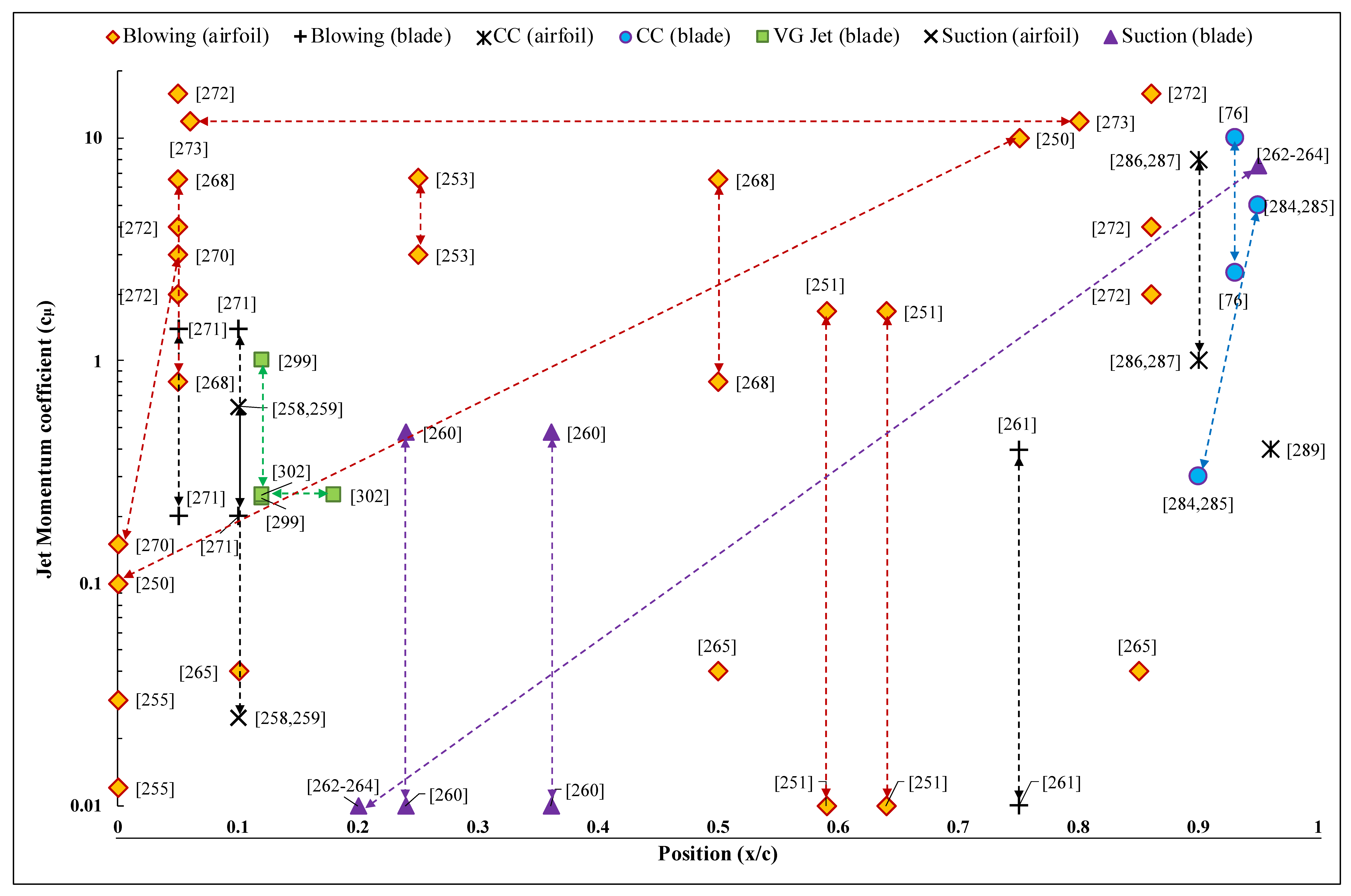
This flow control requires slots/holes in the profile where air can be blown or sucked. These holes are to be placed upstream of the separation point, which itself traverses with the AOA. Therefore, a combined actuation at the leading and trailing edge is desired. However, the presence of multiple slots on the aerofoil surface modifies the effective profile and augments drag, which become prominent at high AOAs. Figure 10 displays a plot of the literature survey of the blowing-suction flow-control, in terms of the jet-momentum coefficient (Cµ) as a function of the chordwise position (x/c).
Prandtl [242] is accredited to introduce the idea of tailoring the boundary-layer characteristics for the desired aerodynamic performance. Since then, blow-suction-flow control was explored for numerous applications [85,241,243,244]. The blow-type control is popular in aviation for stall-extension and landing-speed reduction, as it shortens the runway requirement [245]. Likewise, suction-type control holds promise for sustaining laminar flow over the wings, which reduces the skin-friction drag and improves the fuel economy of the aircraft [244,246].
The blowing mechanism was modified for regulated pulsed blowing to establish control with lesser mass-flow. The fluid-actuators are designed to be triggered by external pressure differential via feeding channels, to produce tangential air jets. The frequency and amplitude of the jet-sweep is dictated by the pressure differential or actuator geometry [247,248,249]. An extensive description of the potential of pulsed blowing for flow control and stall delay is presented in [250,251,252,253,254,255,256]. The effectiveness of periodic blowing is reported to be dependent on slot-location, jet-momentum coefficient, jet pulsed frequency, and the aerofoil profile [250]. Moreover, pulsed blowing was shown to be superior to steady blowing in terms of enhanced performance [250,253,254]. However, in terms of dynamic-stall control [253], its flow-control effectiveness was found to deteriorate upon increment in reduced frequency (F+) and mean oscillatory angles. Meanwhile, the pulsating jets are characterized by a pair of streamwise out-of-phase counterrotating vortices, which empower them for maximum pressure recovery and flow control [254]. A detailed parametric study on pulsation frequency (F+) and momentum coefficient (Cµ) focused toward flow control using pulsating jets, can be found in [255]. Based on the study results, it is ascertained that F+ of unity kerbs the oscillatory amplitude and improves mean load response, whereas Cµ increment is recommended for massively detached flow conditions. The application of pulsed blowing extends to wind turbines [256], demonstrating up to 60% lift enhancement, with stall-extension and significant drag mitigation.
A comparison of the potential of the blowing mechanism against rigid tabs for aerodynamic enhancement is stressed in [257]. Besides attracting lower maintenance, the blow-type control facilitated flexible and rapid actuation compared to the mechanical systems. For the micro-jet, it enhanced lift and moment, with reduced drag and adverse transient lift [257].
Meanwhile, the potential of suction-flow control for aerodynamic enhancement was explored in several studies, such as the parametric study in [258] tackling the influence of suction amplitude, jet coefficient, and jet width. In the result, researchers determined that suction amplitude governs lift and drag enhancement, whereas jet width improves the glide ratio. The enhancement in glide ratio was also achieved with increment in the suction jet length [259]. Suction-control applications extend as well to wind turbines [260], where the enhancement in power coefficient could rise to 2.4 times that in a 0.5-kW wind turbine, owing to flow reattachment and improved aerodynamic efficiency.
Blowing-suction-flow-control is also applicable in aeroacoustics noise mitigation. Noise suppression of up to 16 dB was achieved by blowing steady-jets into the wake vortices [261]. Here, researchers concluded that blow-jets render the wake into smaller vortices that are blown farther by jet momentum. They ultimately lose negative vorticity due to recirculation, leading to reduced noise-levels. Suction-flow control may also render aeroacoustics noise attenuation of up to 3.5 dB [262], which is attributable to the thinning of the boundary layer that leads to reduction in the characteristic length scales of intrinsic eddies. Its application on an NREL 5-MW wind turbine may result in a 2.5-dB noise suppression with net turbine power enhancement of 2% [263]. Nevertheless, the noise attenuation (max 3.2 dB) was shown to be detrimental to the turbine performance. Eventually, the outcomes were tested on N117 industrial wind turbine [264], which revealed aeroacoustics noise suppression of nearly 3.6 dB with 4.75% enhancement in total turbine power. Moreover, a cross-over reduction level of 5 dB was obtained, beyond which the turbine performance degraded due to hardware limitations (pump: collector duct, in particular).
Applying the blowing mechanism for aerodynamic load control is also feasible. In [265], the application of pulsating jets reduced the root mean-square (RMS) of the fluctuating load of wind turbine blades by up to 12%. Moreover, load alleviation induced by a suction or pulsed-blowing coupled mechanism [266] is attributable to boundary-layer extraction (suction) and energizing (blowing), unsteady shear-layer excitation, thrust generation and streamwise vortices. Adaptive blowing (regulated steady blowing) was also credited with load-excursion elimination, by controlling boundary-layer separation using jet-momentum flux [267], with a successful demonstration of the eradication of dynamic-stall vortex using jet momentum under deep stall conditions. Next, dynamic blowing was also successfully applied for lift-excursions and dynamic-stall suppression, to achieve nearly constant phase-averaged lift or mitigated unsteady-aerodynamic loads [268], whereas passive adaptive blowing may be ideal for load alleviation and reduced blade-root bending and tip deflections [269]; mainly, this self-regulatory mechanism is governed by pressure-differential feedback obtained from control-ports on either side of the aerofoil/blade.
An alternative is the use of the counter-flow blow technique, which injects low-energy tangential-jets against the global flow, from the pressure side of the aerofoil near the leading-edge stagnation point. The delay in separation and stall control is attributed to boundary-layer enhancement and virtual-shaping effect [270]. The former is triggered by turbulence-increment away from the wall, which prompts the transfer of high-energy outer flow inwards, whereas the latter makes the aerofoil aerodynamically thicker at high AOAs.
Another flow-control technique employs an alternating jet (blowing/sucking) to obtain a zero, mean air-mass transfer over each sinusoidal oscillatory period. The flow-control effectiveness was reported to be dependent on the oscillatory-jet momentum, frequency, and incident angle [271], and it demonstrated lift-coefficient enhancement of up to 20% in the blade stall region [271].
Simultaneously applying a co-flow jet (CFJ) with the blowing-suction mechanism, featuring injection and extraction ports near the leading and trailing edge, respectively, is more effective than individual blowing/sucking flow control, and it produces lift enhancements of 40–100% over high AOAs [272]. Similar findings were reported by [273], highlighting improved lift, stall margin, and drag mitigation.
2.5.1. Circulation Control
A variant of the conventional blow-type control mechanism, circulation control (CC), works on the Coanda effect [274,275]. It tangentially injects high-momentum air into the boundary layer, particularly at the curved/rounded trailing edge of aerofoil. The authority of high-velocity jet shifts the stagnation point toward the pressure side thereby, improving the overall aerofoil circulation and sectional lift coefficient [76].
Extensive numerical [76,276,277,278,279,280] and experimental [276,281,282,283] research was conducted on CC. One of the concepts involves increasing the trailing-edge curvature to intensify the CC-effectiveness; however, this attracts a huge drag penalty in the absence of a CC-jet [281]. Therefore, the trailing-edge curvature is flattened on the pressure side to improve aerodynamic performance [281].
Accordingly, several studies centered on the design and applicability of Coanda jets in wind turbines exist. For example, the implementation of CC on an NREL Phase-VI wind turbine led to enhanced circulation with the increment in Cµ [76], although the effect was lost at higher wind speeds due to shifting of separation point upstream of the jet. Extensive parametric studies on CC-jets showed the potential of enhancing glide ratio by careful rounding of the trailing edge, along with tailoring of Coanda-jet thickness and momentum coefficient [284,285]. A comparative study on the feasibility of applying CC on a wind turbine presented in [286] reported significant enhancements in lift and drag by separation control and super-circulation. In particular, the lift enhancement was governed by increasing Cµ and/or decreasing slot-height; nevertheless, the performance of the modified aerofoil was degraded in the absence of CC-actuation, (as compared to the reference aerofoil). Therefore, a partial-CC (PCC) flow-control design was proposed as an effective, efficient, and reliable flow control for blunt trailing-edge wind turbines [287], generating higher lift increments with slightly increased drag, at lesser Coanda-actuation power. However, unlike CC, PCC does not degrade performance in the absence of actuation. Moreover, PCC outperformed CC in terms of the aerodynamic figure of merit (AFM) and control efficiency.
The CC-control was successfully implemented for 2D stall suppression, while appreciably improving the effectiveness of CC at high AOAs [280]. Moreover, the jet-momentum requirement to achieve specified flow-control performance was halved in the presence of the Coanda extension, which considerably reduced the actuation-power demand [288]. A comparative study on the effectiveness of CC, triggered by plasma actuators and blowing, reported the superiority of the latter, by generating twice enhancement in the lift coefficient [289].
2.5.2. Vortex Generator Jet (VGJ)
A vortex generator jet (VGJ) is airstream-projected into the crossflow through the aerofoil/blade profile to generate streamwise vortices, and these vortices are dominantly embedded in the boundary layer and lead to entrainment of high-momentum flow toward the surface, thereby controlling flow separation [290]. Besides separation control, a VGJ also augments the lift coefficient and delays stall [291].
In the late 1950s, the concept of VGJs was first proposed by Wallis [292]. Based on extensive research, beside their ability to eliminate drag penalty, VGJs are deemed equally effective as traditional VGs [155]. The separation-control effectiveness of VGJ-arrays is documented in [293], whereas a detailed study [294] asserts that the characteristics of the vortices produced by VGs and VGJs are similar, except that those of VGJs decay faster.
A modified version of the VGJs, referred to as pulsed vortex generator jet (PVGJs), is aimed at the production of pulsed airstreams. PVGJs are highly efficient for stall control, as they induce stronger crossflow vortices while requiring lower mass-flow due to the reduced duty-cycle (usually 10–50%) [250,295,296,297]. Further, PVGJs may be optimized to generate coherent structures, by tailoring-pulsing frequency, jet-velocity ratio, and duty-cycle.
The stall-controllability of VGJs is effective, with significant enhancements in coefficients of lift (+10%) and drag (−50%) [298]. The performance of VGJs is said to improve with Cμ. A passive-VGJ mechanism governed by pressure differential was investigated to exhibit separation delay and stall suppression, besides enhancement in aerodynamic performance [299]. PVGJs also demonstrated separation control, while enhancing lift by up to 20% and limiting the net pressure-loss to 40% [300]. Further, VGJs exhibited effective separation and stall control, induced by shockwaves in transonic flow [301]. For the potential of VGJs for flow control on wind turbines [302], they were reported to demonstrate significant lift enhancement and stall delay, aside from their potential for improving the power output (especially in under-rated conditions).
3. Discussion
3.1. Prospects
The above literature survey of flow-control devices reflects the great prospects of performance enhancement in wind turbines. Flaps are among the most reliable, effective, and low-maintenance aerodynamic enhancement devices. The ATEG-flaps employ minor surface-deflections to generate significant aerodynamic enhancements. Practically, the low surface-inertia of ATEGs facilitates high-frequency operations to tackle extreme and fatigue loads with quick local spanwise-deflections. Gurney flaps offer the benefits of being installed as a retrofit device, without drastic aerodynamic penalties for the blade [83,303]. Next, the minute size of gurney flaps facilitates rapid actuation for effective load control, besides being economical in power and cost demand. Microtabs offer effective load control comparable to flaps, without considerable drag penalty. Moreover, microtabs feature small size and low inertia, allowing rapid deployment and control at slight actuation power, and they can be integrated as arrays or modules to attain global aerodynamic effects. Additionally, the small size of vortex generators allows them to be distributed over the profile to exhibit excellent separation delay and stall suppression with aerodynamic enhancements. Plasma actuators offer ultralight, compact, and robust mechanical architecture, which is economical in terms of actuation power and costs. Plasma actuators operate over a wide range of flow-control modes generating significant aerodynamic enhancements. Blowing-suction-flow-control is quite effective in separation and stall suppression, even at high operational angles. They also exhibit potential for load alleviation and aeroacoustics noise suppression.
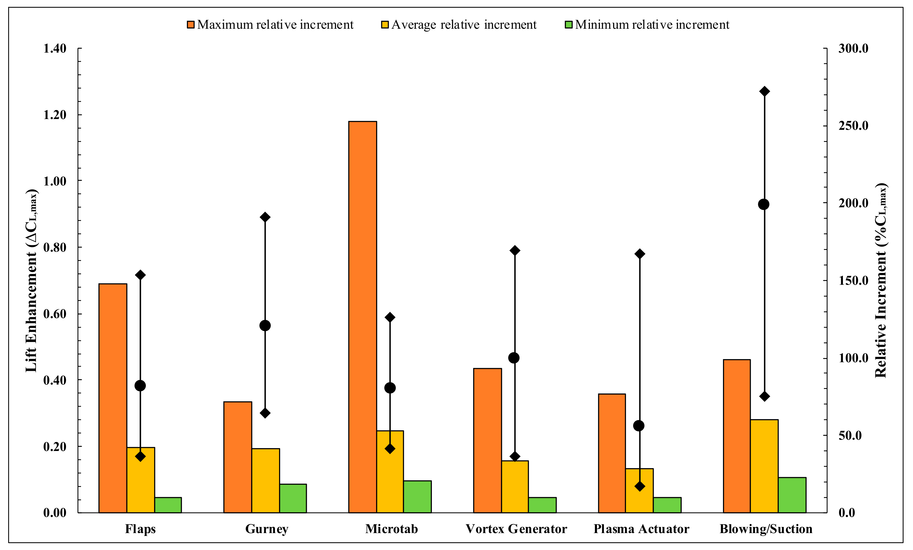
Figure 11 displays a comprehensive comparison of the aerodynamic performance of the flow-control devices. The survey conducted in this review was used for data compilation of the lift controllability of the devices in terms of ΔCLmax and relative enhancement (%CLmax). The former parameter signifies enhancement in the maximum lift coefficient, while the latter depicts the relative increment (%) of the same. The data is extracted particularly from wind turbine specific studies covered in the survey. The observation exists that the highest ΔCLmax was reflected in the co-flow (blowing-suction) jet mechanism, whereas the average lift controllability (ΔCLmax) was delivered best in the case of blowing-suction, followed by gurney flaps. The maximum and average lift enhancement by flaps, microtabs, vortex generators and plasma actuators are comparable. In general, the lift controllability by vortex generators, plasma actuators, and blowing-suction-flow-control are superior at high AOAs, due to their excellent stall-extension capabilities. However, at lower AOAs (pre-stall) the enhancements are comparatively less lucrative, except for CC (blowing) and co-flow (blowing-suction) jets.
3.2. Challenges
Definite shortcomings exist with the application of the above-discussed advanced flow-control mechanisms on wind turbines. For example, the aerodynamic performance of the rigid-flaps is dependent on size, which draws drag penalty and adds weight. Additionally, the flap size exhibits a scale-down limitation of being higher than the boundary layer to maintain effectiveness at high AOAs. Moreover, they cannot be operated at extreme deployments, as sharp changes in the camber exhibit a detrimental effect on the glide ratio [7]. Besides, the flaps need segregation to adjust the local blade deflections and prevent spanwise-bending of the blade, which increases complexity, weight, and cost. Other concerns involve mechanical wear/tear and aeroacoustics noise. The deployment of ATEGs exhibits a high-energy requirement, aside from the fatigue concerns for the skin. The durability and reliability of the compliant structure and components are still being investigated.
Essentially, ATEGs may be prone to creep and degradation over long-term applications, which could limit the system performance. Gurney flaps can generally be used as a supplementary performance enhancement device. The application of gurney-arrays for global flow control over the wind turbine blades is still being researched. Shortcomings associated with microtabs circles around flow leakage, aeroacoustics noise, and complex integration. The tab-gaps drastically affect load controllability besides increasing vulnerability to dust, moisture, and rain. Further, MiTEs require blunt-edge blades/aerofoils, which exhibit poor aerodynamic performance when MiTEs are not activated. Aeroacoustics noise was also found to be higher in the case of blunt-edge aerofoils/blades [304]. The primary disadvantage of VGs is the increment of parasitic drag, under attached flow conditions. This is highly undesirable for blade performance and aeroelastic response. Smart VGs effectively delay stall but fail to tailor the overall lift response of blade, which is more crucial for control mechanism. Further, Smart VGs and HiMVGs require slots in the blade geometry, which are major concern for performance deterioration and noise generation. The primary limitation of plasma actuators is their sensitivity to the flow characteristics, with them becoming completely ineffective beyond Re = 105 [305]. Another challenge is the maintenance of a stable electric-wind in all the operational conditions. Thus, the reliability of plasma actuators under rain, snow, hail, dust, lightening, etc., needs to be investigated thoroughly [306,307]. Lastly, the energy conversion process is inefficient with high thermal losses, which need refinement to enhance the power efficiency [195]. The challenge with the blowing-suction mechanism is the incorporation of the actuation system into the blade, which requires major redesigning to reduce the complexity, weight, and cost, while ensuring structural strength and integrity. Next, the drilling of slots in the blade profile undermines strength, and the slots are susceptible to blockages (by ice, dust, water, etc.), which may generate hazardous vibrations and loads due to degraded performance. Rapid flow control requires valves to be housed near slots, creating accessibility issues for repair and maintenance, while exposing the electrical system to lightning strikes. The arrangement of hub-based compressors/pumps and air-tubes passing through the rotating hub-blade joint pose another massive assignment. Furthermore, the induction of compressed air-jet into the cross-stream poses as a noise threat.
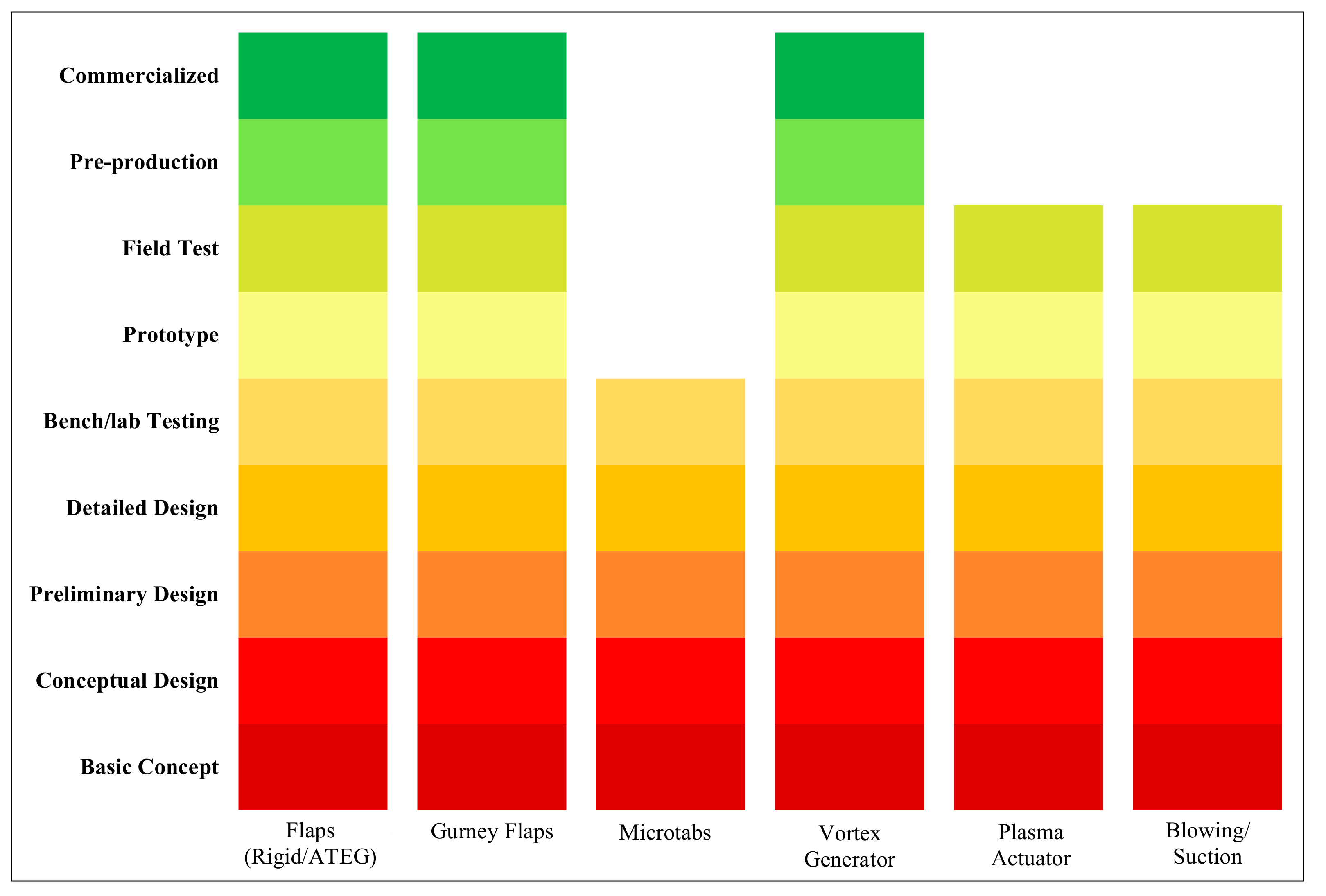
The Technical Readiness Level (TRL) of the discussed flow-control device is presented in Figure 12.
Conclusively, most of the devices received rigorous testing in the form of prototypes and field tests (TRL 6–7), to establish their feasibility in terms of reliability, control, and safety. The potential of some, such as flaps (rigid/ATEG), gurney flaps, and vortex generators, were proven, leading to their current commercialization (TRL 9). In addition, they are popular as power-augmentation upgrades in the industry. Flaps and vortex generators were employed under the Energy Thrust program by Siemens Gamesa, to attain 3–5% increment in the AEP [308]. Likewise, Power Plus program by Vestas offers up to 5% AEP enhancement, by installing vortex generators and gurney flaps as aerodynamic upgrades to the wind turbines [309]. Other flow-control devices, i.e., microtabs, plasma actuation, and blowing-suction control, still need to be assessed under pre-production for manufacturability and overall costs (production and operations) of the wind turbine, prior to commercialization.
3.3. Outlook
Flow-control devices hold great potential for wind turbine performance enhancement by tailoring aerodynamic response and load control. The design and development of such devices is still under investigation, with the need to identify the critical parameters and to evade design restrictions to ensure their manufacturability and subsequent commercialization. Further, to obtain the ideal response, these devices are governed by advanced control schemes. Optimization of such control strategies will dictate the scaling of wind turbine size in the future, and thus, essentiates efforts toward their development, based on the accumulated knowledge on unsteady aerodynamics, aeroelastic response, fluid-structure interactions, and advanced dynamics and control. The requirement for multi-scale models to further enhance understanding of interactions between the environment and the wind turbine also exists, such as in the case of reduction in COE and eventual growth of the wind industry, which are being challenged by scale-up limitations. Therefore, a combined effort in fundamental and industrial research is desirable to bring forth wind technology to the advanced stage, that is, of “outsmarting” the scaling laws.
4. Conclusions
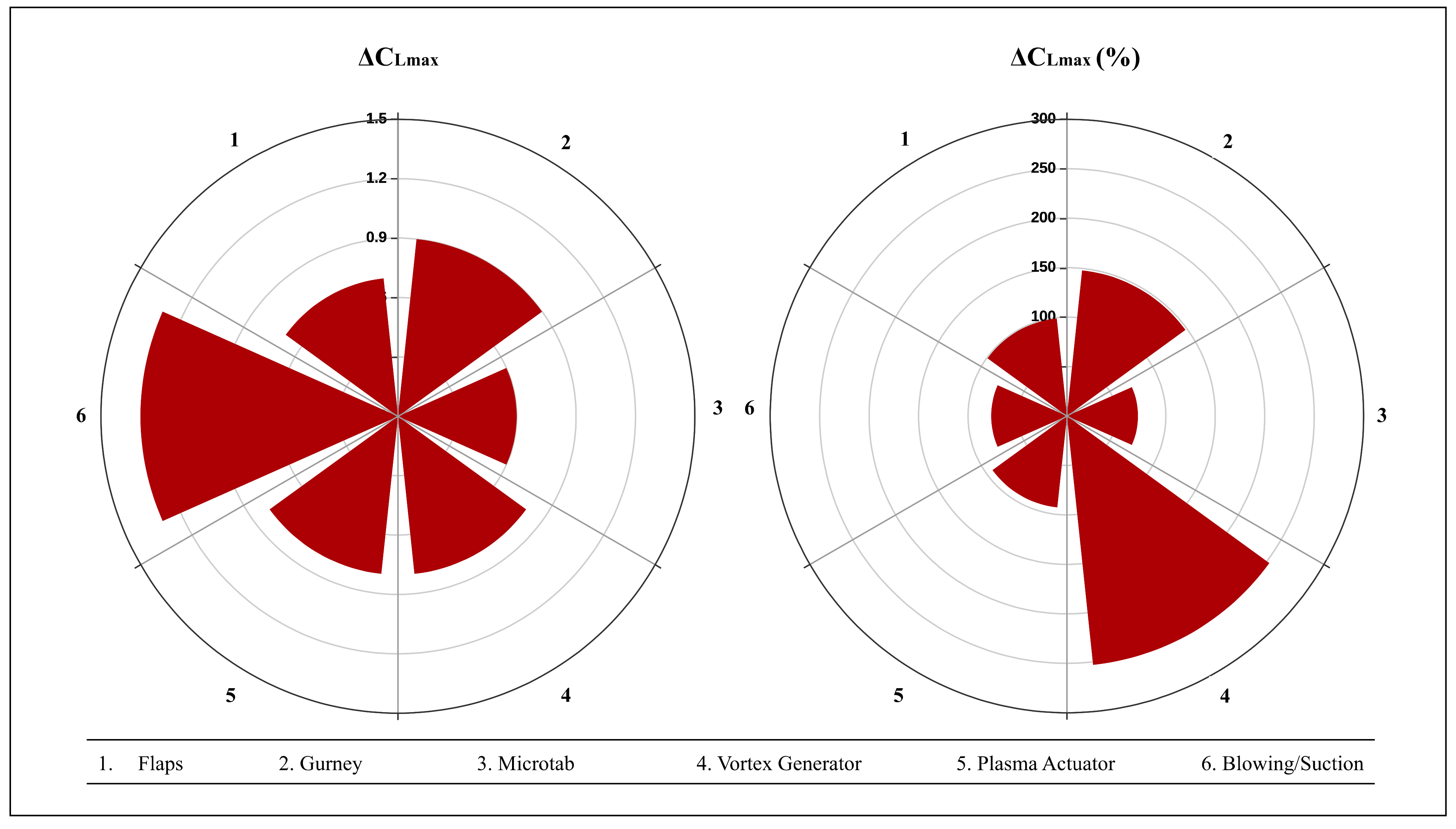
The rapidly growing wind-energy industry has been accompanied with the demand for larger wind turbines. Accordingly, the massive blades feature of multi-MW turbines is prone to fatal extreme and fatigue loads and vibrations. Additionally, these blades face intensified turbulence, local gust-induced fluctuations, wind shear, blade-tower interference, and yaw or tilt misalignment, among others, which drastically affect the structural lifecycle and adversely affect the overall COE. In order to compete with traditional power sources, the COE associated with wind energy needs to be reduced. Flow-control devices offer the potential of significant load alleviation and vibration suppression, aside from improved overall aerodynamic response and wind turbine power output. This study-review of flow-control devices attests their aerodynamic controllability for performance enhancement. As shown in Figure 13, the maximum lift enhancement (ΔCLmax) ranges from 0.6–1.3, with impressive relative enhancements (%CLmax) of 72 to 253%. Most of these devices cleared field tests (TRL 7) and are presently at different stages toward commercialization (TRL 9), while flaps and vortex generators are already popular as upgrades in the industry for AEP enhancements of 3 to 5% on multi-MW wind turbines.
As such, this review aimed to present state-of-the-art flow-control devices that hold the potential of contributing exceptionally toward wind turbine performance enhancement.
Author Contributions
Resources, formal analysis, visualization, writing—original draft preparation M.Z.A.; Conceptualization, writing—review and editing, supervision F.K.O. All authors have read and agreed to the published version of the manuscript.
Funding
This research received no external funding.
Institutional Review Board Statement
Not applicable.
Informed Consent Statement
Not applicable.
Data Availability Statement
The data presented in this study are available on request from the corresponding author.
Conflicts of Interest
The authors declare no conflict of interest.
Nomenclature
| AEP | Annual Energy Production |
| AOA | Angle of Attack |
| ATEG | Adaptive Trailing-edge Geometry |
| CC | Circulation Control |
| COE | Cost of Energy |
| DBD | Dielectric Barrier Discharge |
| GW | Gigawatts |
| HiMVG | High-Frequency Micro Vortex Generator |
| MiTE | Mini Trailing-edge Effectors |
| MVG | Micro Vortex Generator |
| MW | Megawatts |
| NREL | National Renewable Energy Laboratory |
| TRL | Technology Readiness Level |
| VG | Vortex Generator |
| VGJ | Vortex Generator Jet |
References
- IRENA. Renewable Energy Statistics 2020; International Renewable Energy Agency: Abu Dhabi, United Arab Emirates, 2020. [Google Scholar]
- GWEC. Global Wind Report 2019; Global Wind Energy Council: Brussels, Belgium, 2020. [Google Scholar]
- Offshore Wind Turbine SG 14-222 DD I Siemens Gamesa. Available online: https://www.siemensgamesa.com/en-int/products-and-services/offshore/wind-turbine-sg-14-222-dd (accessed on 13 July 2020).
- Gad-el-Hak, M. Overview of Turbulence Control Research in U.S.A. In Proceedings of the Symposium on Smart Control of Turbulence, Tokyo, Japan, 2–3 December 1999; pp. 1–20. [Google Scholar]
- Kral, L.D. Active Flow Control Technology. In ASME Fluids Engineering Technical Brief; Washington University: St. Louis, MO, USA, 1998. [Google Scholar]
- Chopra, I. Review of State of Art of Smart Structures and Integrated Systems. AIAA J. 2002, 40, 2145–2187. [Google Scholar] [CrossRef]
- Abbott, I.H.; von Doenhoff, A.E. Theory of Wing Sections; Courier Corporation: New York, NY, USA, 1959. [Google Scholar]
- Berg, D.E.; Zayas, J.R.; Lobitz, D.W.; van Dam, C.P.; Chow, R.; Baker, J.P. Active Aerodynamic Load Control of Wind Turbine Blades; American Society of Mechanical Engineers Digital Collection; American Society of Mechanical Engineers: New York, NY, USA, 2009; pp. 1119–1127. [Google Scholar] [CrossRef] [Green Version]
- Migliore, P.G.; Miller, L.S.; Quandt, G.A. Wind Turbine Trailing Edge Aerodynamic Brakes; National Renewable Energy Laboratory: Golden, CO, USA, 1995.
- Miller, S.; Migliore, P.G.; Quandt, G.A. An Evaluation of Several Wind Turbine Trailing-Edge Aerodynamic Brakes. J. Sol. Energy Eng. 1996, 118, 198–203. [Google Scholar] [CrossRef]
- Miller, L.S. Experimental Investigation of Aerodynamic Devices for wind Turbine Rotational Speed Control: Phase, I.I.; National Renewable Energy Laboratory: Golden, CO, USA, 1996. [CrossRef] [Green Version]
- Somers, D.M. Effect of Flap Deflection on Section Characteristics of S813 Airfoil; Period of Performance: 1993–1994; National Renewable Energy Laboratory: Golden, CO, USA, 2005. [CrossRef] [Green Version]
- Ramsay, R.; Janiszewska, J.; Gregorek, G. Wind tunnel testing of an S809 spoiler flap model. In Proceedings of the 35th Aerospace Sciences Meeting and Exhibit, Reno, NV, USA, 6–9 January 1997; American Institute of Aeronautics and Astronautics: Reston, VA, USA. [Google Scholar] [CrossRef]
- Stuart, J.G.; Wright, A.D.; Butterfield, C.P. Considerations for an Integrated Wind Turbine Controls Capability at the National Wind Technology Center: An Aileron Control Case Study for Power Regulation and Load Mitigation; National Renewable Energy Laboratory: Golden, CO, USA, 1996. [CrossRef] [Green Version]
- Stuart, J.; Wright, A.; Butterfield, C. Wind turbine control systems—Dynamic model development using system identification and the FAST structural dynamics code. In Proceedings of the 35th Aerospace Sciences Meeting and Exhibit, Reno, NV, USA, 6–9 January 1997; American Institute of Aeronautics and Astronautics: Reston, VA, USA, 1997. [Google Scholar] [CrossRef] [Green Version]
- Lee, J.-W.; Han, J.-H.; Shin, H.-K.; Bang, H.-J. Active load control of wind turbine blade section with trailing edge flap: Wind tunnel testing. J. Intell. Mater. Syst. Struct. 2014, 25, 2246–2255. [Google Scholar] [CrossRef]
- Castaignet, D.; Barlas, T.; Buhl, T.; Poulsen, N.K.; Wedel-Heinen, J.J.; Olesen, N.A.; Bak, C.; Kim, T. Full-scale test of trailing edge flaps on a Vestas V27 wind turbine: Active load reduction and system identification. Wind Energy 2014, 17, 549–564. [Google Scholar] [CrossRef]
- Fischer, J.; Eisele, O.; Pechlivanoglou, S.; Vey, S.; Nayeri, C.N.; Paschereit, C.O. Development of a medium scale research hawt for inflow and aerodynamics research in the large wind tunnel of TU berlin wind tunnel. In Proceedings of the 12th German Wind Energy Conference (DEWEK), Bremen, Germany, 19–20 May 2015. [Google Scholar]
- Vey, S.; Marten, D.; Pechlivanoglou, G.; Nayeri, C.; Paschereit, C.O. Experimental and Numerical Investigations of a Small Research Wind Turbine. In Proceedings of the 33rd AIAA Applied Aerodynamics Conference, Dallas, TX, USA, 22–26 June 2015; American Institute of Aeronautics and Astronautics: Reston, VA, USA, 2015. [Google Scholar] [CrossRef]
- Plumley, C.; Leithead, W.; Jamieson, P.; Bossanyi, E.; Graham, M. Comparison of individual pitch and smart rotor control strategies for load reduction. J. Phys. Conf. Ser. 2014, 524, 012054. [Google Scholar] [CrossRef] [Green Version]
- Ng, B.F.; Hesse, H.; Kerrigan, E.C.; Palacios, R.; Graham, J.M.R. Efficient aeroservoelastic modeling and control using trailing-edge flaps of wind turbines. In Proceedings of the 2014 UKACC International Conference on Control (CONTROL), Loughborough, UK, 9–11 July 2014; pp. 1–6. [Google Scholar] [CrossRef]
- Ng, B.F.; Palacios, R.; Kerrigan, E.C.; Graham, J.M.R.; Hesse, H. Aerodynamic load control in horizontal axis wind turbines with combined aeroelastic tailoring and trailing-edge flaps. Wind Energy 2016, 19, 243–263. [Google Scholar] [CrossRef]
- Lackner, M.A.; van Kuik, G. A comparison of smart rotor control approaches using trailing edge flaps and individual pitch control. Wind Energy 2010, 13, 117–134. [Google Scholar] [CrossRef] [Green Version]
- Ungurán, R.; Kühn, M. Combined individual pitch and trailing edge flap control for structural load alleviation of wind turbines. In Proceedings of the 2016 American Control Conference (ACC), Boston, MA, USA, 6–8 July 2016; pp. 2307–2313. [Google Scholar] [CrossRef]
- Fischer, A.; Madsen, H.A. Investigation of the theoretical load alleviation potential using trailing edge flaps controlled by inflow data. Wind Energy 2016, 19, 1567–1583. [Google Scholar] [CrossRef]
- Oltmann, N.-C.; Sobotta, D.; Hoffmann, A. Load reduction of wind turbines using trailing edge flaps. Energy Procedia 2017, 136, 176–181. [Google Scholar] [CrossRef]
- Smit, J.; Bernhammer, L.O.; Navalkar, S.T.; Bergami, L.; Gaunaa, M. Sizing and control of trailing edge flaps on a smart rotor for maximum power generation in low fatigue wind regimes. Wind Energy 2016, 19, 607–624. [Google Scholar] [CrossRef]
- Chen, Z.J.; Stol, K.A.; Mace, B.R. Wind turbine blade optimisation with individual pitch and trailing edge flap control. Renew. Energy 2017, 103, 750–765. [Google Scholar] [CrossRef]
- Zhang, W.; Bai, X.; Wang, Y.; Han, Y.; Hu, Y. Optimization of sizing parameters and multi-objective control of trailing edge flaps on a smart rotor. Renew. Energy 2018, 129, 75–91. [Google Scholar] [CrossRef]
- Montinari, P.; Gualdoni, F.; Croce, A.; Bottasso, C.L. Ultimate and fatigue load mitigation by an inertial-driven passive flap, using a geometrically exact multibody formulation. J. Wind Eng. Ind. Aerodyn. 2018, 175, 169–178. [Google Scholar] [CrossRef]
- Wei, X.; Ng, B.F.; Zhao, X. Aeroelastic load control of large and flexible wind turbines through mechanically driven flaps. J. Frankl. Inst. 2019, 356, 7810–7835. [Google Scholar] [CrossRef]
- Basualdo, S. Load Alleviation on Wind Turbine Blades Using Variable Airfoil Geometry. Wind Eng. 2005, 29, 169–182. [Google Scholar] [CrossRef]
- Jacob, J.D. On the Fluid Dynamics of Adaptive Airfoils. In Proceedings of the 1998 ASME International Mechanical Engineering Congress and Exposition Anaheim, Anaheim, CA, USA, 15–20 November 1988. [Google Scholar]
- Monner, H.P. Realization of an optimized wing camber by using formvariable flap structures. Aerosp. Sci. Technol. 2001, 5, 445–455. [Google Scholar] [CrossRef]
- Kota, S.; Hetrick, J.A. Adaptive Compliant Wing and Rotor System. CA2518080C, 5 February 2014. [Google Scholar]
- Campanile, L.F.; Anders, S. Aerodynamic and aeroelastic amplification in adaptive belt-rib airfoils. Aerosp. Sci. Technol. 2005, 9, 55–63. [Google Scholar] [CrossRef]
- Berry, P. Segmented Flap with Variable Camber for Aircraft Wing. WO1997044238A1, 27 November 1997. [Google Scholar]
- Brown, S.T. Variable Camber Flap End Seal. US4427169A, 24 January 1984. [Google Scholar]
- Kudva, J.; Appa, K.; Martin, C.; Jardine, A.; Sendeckyj, G.; Harris, T.; McGowan, A.; Lake, R. Design, fabrication, and testing of the DARPA/Wright Lab “smart wing” wind tunnel model. In Proceedings of the 38th Structures, Structural Dynamics, and Materials Conference, Kissimmee, FL, USA, 7–10 April 1997; American Institute of Aeronautics and Astronautics: Reston, VA, USA, 1997. [Google Scholar]
- Bartley-Cho, J.D.; Wang, D.P.; Martin, C.A.; Kudva, J.N.; West, M.N. Development of High-rate, Adaptive Trailing Edge Control Surface for the Smart Wing Phase 2 Wind Tunnel Model. J. Intell. Mater. Syst. Struct. 2014, 15, 279–291. [Google Scholar] [CrossRef]
- Straub, F.K.; Ngo, H.T.; Anand, V.; Domzalski, D.B. Development of a piezoelectric actuator for trailing edge flap control of full scale rotor blades. Smart Mater. Struct. 2001, 10, 25–34. [Google Scholar] [CrossRef]
- Straub, F.K.; Merkley, D.J. Design of a servo-flap rotor for reduced control loads. Smart Mater. Struct. 1996, 5, 68–75. [Google Scholar] [CrossRef]
- Troldborg, N. Computational Study of the Risø-B1-18 Airfoil with a Hinged Flap Providing Variable Trailing Edge Geometry. Wind Eng. 2005, 29, 89–113. [Google Scholar] [CrossRef]
- Bak, C.; Gaunaa, M.; Andersen, P.B.; Buhl, T.; Hansen, P.; Clemmensen, K.; Moeller, R. Wind Tunnel Test on Wind Turbine Airfoil with Adaptive Trailing Edge Geometry. In Proceedings of the 45th AIAA Aerospace Sciences Meeting and Exhibit, Reno, NV, USA, 8–11 January 2007. [Google Scholar]
- Theodorsen, T. General Theory of Aerodynamic Instability and the Mechanism of Flutter; National Advisory Committee for Aeronautics: Washington DC, USA, 1949.
- Leishman, J.G. Unsteady lift of a flapped airfoil by indicial concepts. J. Aircr. 1994, 31, 288–297. [Google Scholar] [CrossRef]
- Gaunaa, M. Unsteady 2D Potential-Flow Forces and a Thin Variable Geometry Airfoil Undergoing Arbitrary Motion; Risoe National Laboratory Wind Energy Department: Roskilde, Denmark, 2006.
- Buhl, T.; Gaunaa, M.; Bak, C. Potential Load Reduction Using Airfoils with Variable Trailing Edge Geometry. J. Sol. Energy Eng. 2005, 127, 503–516. [Google Scholar] [CrossRef]
- Andersen, P.B.; Gaunaa, M.; Buhl, T. Load Alleviation on Wind Turbine Blades using Variable Airfoil Geometry. In Proceedings of the 2006 European Wind Energy Conference & Exhibition, Athens, Greece, 27 February–2 March 2006. [Google Scholar]
- Hulskamp, A.W.; Beukers, A.; Bersee, H.E.N.; van Wingerden, J.W.; Barlas, T. Design of a wind tunnel scale model of an adaptive wind turbine blade for active aerodynamic load control experiments. In Proceedings of the ICCM 16: 16th International Conference on Composite Materials, Kyoto, Japan, 8–13 July 2007. [Google Scholar]
- Barlas, T.; van Wingerden, J.W.; Hulskamp, A.; van Kuik, G. Closed-Loop Control Wind Tunnel Tests on an Adaptive Wind Turbine Blade for Load Reduction. In Proceedings of the 46th AIAA Aerospace Sciences Meeting and Exhibit, Reno, NV, USA, 7–10 January 2008; American Institute of Aeronautics and Astronautics: Reston, VA, USA, 2008. [Google Scholar] [CrossRef] [Green Version]
- Barlas, T.K.; van Kuik, G.A.M. State of the art and prospectives of smart rotor control for wind turbines. J. Phys. Conf. Ser. 2007, 75, 012080. [Google Scholar] [CrossRef]
- van Wingerden, J.W.; Hulskamp, A.W.; Barlas, T.K.; Marrant, B.; van Kuik, G.A.M.; Molenaar, D.P.; Verhaegen, M. On the proof of concept of a ‘Smart’ wind turbine rotor blade for load alleviation. Wind Energy 2008, 11, 265–280. [Google Scholar] [CrossRef]
- Cairns, D.S.; Blockey, J.C.; Ehresman, J. Design and Feasibility of Active Control Surfaces on Wind Turbine Blade Systems. In Proceedings of the 46th AIAA Aerospace Sciences Meeting and Exhibit, Reno, NV, USA, 7–10 January 2008; American Institute of Aeronautics and Astronautics: Reston, VA, USA, 2008. [Google Scholar] [CrossRef]
- Pechlivanoglou, G.; Wagner, J.; Nayeri, C.; Paschereit, C. Active Aerodynamic Control of Wind Turbine Blades with High Deflection Flexible Flaps. In Proceedings of the 48th AIAA Aerospace Sciences Meeting Including the New Horizons Forum and Aerospace Exposition, Orlando, USA, 4–7 January 2010; American Institute of Aeronautics and Astronautics: Reston, VA, USA, 2010. [Google Scholar] [CrossRef]
- Andersen, P.B. Advanced Load Alleviation for Wind Turbines Using Adaptive Trailing Edge Flaps: Sensoring and Control. Ph.D. Thesis, National Laboratory for Sustainable Energy Risø, D.T.U., Roskilde, Denmark, 2010. [Google Scholar]
- Andersen, P.B.; Henriksen, L.; Gaunaa, M.; Bak, C.; Buhl, T. Deformable trailing edge flaps for modern megawatt wind turbine controllers using strain gauge sensors. Wind Energy 2010, 13, 193–206. [Google Scholar] [CrossRef]
- Barlas, T.K.; van Wingerden, J.W.; Hulskamp, A.W.; van Kuik, G.A.M.; Bersee, H.E.N. Smart dynamic rotor control using active flaps on a small-scale wind turbine: Aeroelastic modeling and comparison with wind tunnel measurements. Wind Energy 2013, 16, 1287–1301. [Google Scholar] [CrossRef]
- Daynes, S.; Weaver, P.M. A morphing trailing edge device for a wind turbine. J. Intell. Mater. Syst. Struct. 2012, 23, 691–701. [Google Scholar] [CrossRef]
- Daynes, S.; Weaver, P.M. Design and testing of a deformable wind turbine blade control surface. Smart Mater. Struct. 2012, 21, 105019. [Google Scholar] [CrossRef]
- Wolff, T.; Ernst, B.; Seume, J.R. Aerodynamic behavior of an airfoil with morphing trailing edge for wind turbine applications. J. Phys. Conf. Ser. 2014, 524, 012018. [Google Scholar] [CrossRef] [Green Version]
- Zhang, M.; Tan, B.; Xu, J. Parameter study of sizing and placement of deformable trailing edge flap on blade fatigue load reduction. Renew. Energy 2015, 77, 217–226. [Google Scholar] [CrossRef]
- Bergami, L.; Poulsen, N.K. A smart rotor configuration with linear quadratic control of adaptive trailing edge flaps for active load alleviation. Wind Energy 2015, 18, 625–641. [Google Scholar] [CrossRef] [Green Version]
- Bernhammer, L.O.; van Kuik, G.A.M.; De Breuker, R. Fatigue and extreme load reduction of wind turbine components using smart rotors. J. Wind Eng. Ind. Aerodyn. 2016, 154, 84–95. [Google Scholar] [CrossRef]
- Jost, E.; Lutz, T.; Krämer, E. A Parametric CFD Study of Morphing Trailing Edge Flaps Applied on a 10 MW Offshore Wind Turbine. Energy Procedia 2016, 94, 53–60. [Google Scholar] [CrossRef] [Green Version]
- Zhang, M.; Li, X.; Xu, J. Smart control of fatigue loads on a floating wind turbine with a tension-leg-platform. Renew. Energy 2019, 134, 745–756. [Google Scholar] [CrossRef]
- Zhuang, C.; Yang, G.; Zhu, Y.; Hu, D. Effect of morphed trailing-edge flap on aerodynamic load control for a wind turbine blade section. Renew. Energy 2020, 148, 964–974. [Google Scholar] [CrossRef]
- Liebeck, R.H. Design of Subsonic Airfoils for High Lift. J. Aircr. 1978, 15, 547–561. [Google Scholar] [CrossRef]
- Liu, T.; Montefort, J. Thin-Airfoil Theoretical Interpretation for Gurney Flap Lift Enhancement. J. Aircr. 2007, 44, 667–671. [Google Scholar] [CrossRef]
- Liebeck, R. On the design of subsonic airfoils for high lift. In Proceedings of the 9th Fluid and PlasmaDynamics Conference, San Diego, CA, USA, 14–16 July 1976; American Institute of Aeronautics and Astronautics: Reston, VA, USA, 1976. [Google Scholar] [CrossRef]
- Greenblatt, D.; Vey, S.; Paschereit, O.C.; Meyer, R. Flap Vortex Management Using Active Gurney Flaps. AIAA J. 2009, 47, 2845–2856. [Google Scholar] [CrossRef]
- Storms, B.L.; Jang, C.S. Lift enhancement of an airfoil using a Gurney flap and vortex generators. J. Aircr. 1994, 31, 542–547. [Google Scholar] [CrossRef] [Green Version]
- Myose, R.; Papadakis, M.; Heron, I. Gurney Flap Experiments on Airfoils, Wings, and Reflection Plane Model. J. Aircr. 1998, 35, 206–211. [Google Scholar] [CrossRef]
- Li, Y.; Wang, J.; Zhang, P. Effects of Gurney Flaps on a NACA0012 Airfoil. Flow Turbul. Combust. 2002, 68, 27. [Google Scholar] [CrossRef]
- Timmer, W.A.; van Rooij, R.P.J.O.M. Summary of the Delft University Wind Turbine Dedicated Airfoils. J. Sol. Energy Eng. 2003, 125, 488–496. [Google Scholar] [CrossRef]
- Tongchitpakdee, C.; Benjanirat, S.; Sankar, L.N. Numerical Studies of the Effects of Active and Passive Circulation Enhancement Concepts on Wind Turbine Performance. J. Sol. Energy Eng. 2006, 128, 432–444. [Google Scholar] [CrossRef]
- Troolin, D.R.; Longmire, E.K.; Lai, W.T. Time resolved PIV analysis of flow over a NACA 0015 airfoil with Gurney flap. Exp. Fluids 2006, 41, 241–254. [Google Scholar] [CrossRef]
- Fuglsang, P.; Bak, C. Development of the Risø wind turbine airfoils. Wind Energy 2004, 7, 145–162. [Google Scholar] [CrossRef]
- Tang, D.; Dowell, E.H. Aerodynamic Loading for an Airfoil with an Oscillating Gurney Flap. J. Aircr. 2007, 44, 1245–1257. [Google Scholar] [CrossRef]
- Maughmer, M.D.; Bramesfeld, G. Experimental Investigation of Gurney Flaps. J. Aircr. 2008, 45, 2062–2067. [Google Scholar] [CrossRef]
- Jain, S.; Sitaram, N.; Krishnaswamy, S. Computational Investigations on the Effects of Gurney Flap on Airfoil Aerodynamics. Int. Sch. Res. Not. 2015, 2015, e402358. [Google Scholar] [CrossRef] [Green Version]
- Cole, J.A.; Vieira, B.A.O.; Coder, J.G.; Premi, A.; Maughmer, M.D. Experimental Investigation into the Effect of Gurney Flaps on Various Airfoils. J. Aircr. 2013, 50, 1287–1294. [Google Scholar] [CrossRef]
- Bechert, D.; Meyer, R.; Hage, W. Drag reduction of airfoils with miniflaps—Can we learn from dragonflies? In Proceedings of the Fluids 2000 Conference and Exhibit, Denver, CO, USA, 19–22 June 2000; American Institute of Aeronautics and Astronautics: Reston, VA, USA, 2000. [Google Scholar] [CrossRef] [Green Version]
- Van Dam, C.P.; Chow, R.; Zayas, J.R.; Berg, D.E. Computational Investigations of Small Deploying Tabs and Flaps for Aerodynamic Load Control. J. Phys. Conf. Ser. 2007, 75, 012027. [Google Scholar] [CrossRef] [Green Version]
- Van Dam, C.P.; Berg, D.E.; Johnson, S.J. Active Load Control Techniques for Wind Turbines; Sandia National Laboratories: Albuquerque, NM, USA, 2008. [CrossRef] [Green Version]
- Lee, T. Aerodynamic Characteristics of Airfoil with Perforated Gurney-Type Flaps. J. Aircr. 2009, 46, 542–548. [Google Scholar] [CrossRef]
- Eisele, O.; Pechlivanoglou, G.; Nayeri, C.N.; Paschereit, C.O. Experimental investigation of dynamic load control strategies using active microflaps on wind turbine blades. In Proceedings of the EWEA 2011, Brussels, Belgium, 14–17 March 2011. [Google Scholar]
- Weinzierl, G.; Pechlivanoglou, G.; Nayeri, C.N.; Paschereit, C.O. Performance Optimization of Wind Turbine Rotors With Active Flow Control: Part 2—Active Aeroelastic Simulations; American Society of Mechanical Engineers Digital Collection; American Society of Mechanical Engineers: Copenhagen, Denmark, 2013; pp. 915–927. [Google Scholar] [CrossRef]
- Bach, A.B.; Pechlivanoglou, G.; Nayeri, C.; Paschereit, C.O. Wake Vortex Field of an Airfoil Equipped with an Active Finite Gurney Flap; American Institute of Aeronautics and Astronautics: Kissimmee, FL, USA, 2015. [Google Scholar] [CrossRef]
- Holst, D.; Bach, A.B.; Nayeri, C.N.; Paschereit, C.O.; Pechlivanoglou, G. Wake Analysis of a Finite Width Gurney Flap. J. Eng. Gas Turbines Power 2016, 138. [Google Scholar] [CrossRef]
- Xie, Y.H.; Jiang, W.; Lu, K.; Zhang, D. Numerical investigation into energy extraction of flapping airfoil with Gurney flaps. Energy 2016, 109, 694–702. [Google Scholar] [CrossRef]
- Dighe, V.V.; Avallone, F.; Tang, J.; van Bussel, G. Effects of Gurney Flaps on the Performance of Diffuser Augmented Wind Turbine. In Proceedings of the 35th Wind Energy Symposium, Grapevine, TX, USA, 9–13 January 2017; American Institute of Aeronautics and Astronautics: Reston, VA, USA, 2017. [Google Scholar] [CrossRef]
- Fernandez-Gamiz, U.; Zulueta, E.; Boyano, A.; Ansoategui, I.; Uriarte, I. Five Megawatt Wind Turbine Power Output Improvements by Passive Flow Control Devices. Energies 2017, 10, 742. [Google Scholar] [CrossRef] [Green Version]
- Fernandez-Gamiz, U.; Gomez-Mármol, M.; Chacón-Rebollo, T. Computational Modeling of Gurney Flaps and Microtabs by POD Method. Energies 2018, 11, 2091. [Google Scholar] [CrossRef] [Green Version]
- Aramendia, I.; Fernandez-Gamiz, U.; Zulueta, E.; Saenz-Aguirre, A.; Teso-Fz-Betoño, D. Parametric Study of a Gurney Flap Implementation in a DU91W(2)250 Airfoil. Energies 2019, 12, 294. [Google Scholar] [CrossRef] [Green Version]
- Saenz-Aguirre, A.; Fernandez-Gamiz, U.; Zulueta, E.; Ulazia, A.; Martinez-Rico, J. Optimal Wind Turbine Operation by Artificial Neural Network-Based Active Gurney Flap Flow Control. Sustainability 2019, 11, 2809. [Google Scholar] [CrossRef] [Green Version]
- Baker, J.P.; Standish, K.J.; van Dam, C.P. Two-Dimensional Wind Tunnel and Computational Investigation of a Microtab Modified Airfoil. J. Aircr. 2007, 44, 563–572. [Google Scholar] [CrossRef]
- Yen, D.; van Dam, C.; Braeuchle, F.; Smith, R.; Collins, S. Active load control and lift enhancement using MEM translational tabs. In Proceedings of the Fluids 2000 Conference and Exhibit, Denver, CO, USA, 9–20 June 2000; American Institute of Aeronautics and Astronautics: Reston, VA, USA. [Google Scholar]
- Yen, D.; van Dam, C.; Smith, R.; Collins, S. Active load control for wind turbine blades using MEM translational tabs. In Proceedings of the 20th 2001 ASME Wind Energy Symposium, Reno, NV, USA,, 11–14 January 2001; American Institute of Aeronautics and Astronautics: Reston, VA, USA, 2001. [Google Scholar] [CrossRef]
- Nakafuji, D.T.Y.; van Dam, C.P.; Smith, R.L.; Collins, S.D. Active Load Control for Airfoils using Microtabs. J. Sol. Energy Eng. 2001, 123, 282–289. [Google Scholar] [CrossRef]
- Yen Nakafuji, D.T.; van Dam, C.P.; Michel, J.; Morrison, P. Load Control for Turbine Blades: A Non-Traditional Microtab Approach; American Society of Mechanical Engineers Digital Collection; American Society of Mechanical Engineers: New York, NY, USA, 2002; pp. 321–330. [Google Scholar] [CrossRef]
- Standish, K.J.; van Dam, C.P. Computational Analysis of a Microtab-Based Aerodynamic Load Control System for Rotor Blades. J. Am. Helicopter Soc. 2005, 50, 249–258. [Google Scholar] [CrossRef]
- Somers, D.M. Design and Experimental Results for the S809 Airfoil; National Renewable Energy Laboratory: Golden, CO, USA, 1997. [CrossRef] [Green Version]
- Mayda, E.A.; van Dam, C.P.; Nakafuji, D. Computational Investigation of Finite Width Microtabs for Aerodynamic Load Control. In Proceedings of the 43rd AIAA Aerospace Sciences Meeting and Exhibit, Reno, NV, USA, 10–13 January 2005; American Institute of Aeronautics and Astronautics: Reston, VA, USA, 2005. [Google Scholar] [CrossRef]
- Chow, R.; van Dam, C.P. Unsteady Computational Investigations of Deploying Load Control Microtabs. J. Aircr. 2006, 43, 1458–1469. [Google Scholar] [CrossRef] [Green Version]
- Chow, R.; van Dam, C. Computational Investigations of Deploying Load Control Microtabs on a Wind Turbine Airfoil. In Proceedings of the 45th AIAA Aerospace Sciences Meeting and Exhibit, Reno, NV, USA, 8–11 January 2007; American Institute of Aeronautics and Astronautics: Reston, VA, USA, 2007. [Google Scholar] [CrossRef]
- Chow, R.; van Dam, C.P. On the temporal response of active load control devices. Wind Energy 2010, 13, 135–149. [Google Scholar] [CrossRef]
- Bæk, P.; Gaunaa, M.; Sørensen, N.N.; Fuglsang, P. A Comparison of Two Devices for Distributed Active Load Control of Wind Turbine Blades. In Torque 2010: The Science of Making Torque from Wind; European Wind Energy Association (EWEA): Brussels, Belgium, 2010; pp. 611–617. [Google Scholar]
- Baek, P.; Gaunaa, M. Modeling the Temporal Response of a Microtab in an Aeroelastic Model of a Wind Turbine. In Proceedings of the 49th AIAA Aerospace Sciences Meeting including the New Horizons Forum and Aerospace Exposition, Orlando, FL, USA, 4–7 January 2001; American Institute of Aeronautics and Astronautics: Reston, VA, USA, 2011. [Google Scholar] [CrossRef]
- Zayas, J.R.; van Dam, C.P.; Chow, R.; Baker, J.P.; Mayda, E.A. Active Aerodynamic Load Control of Wind Turbine Blades. In Proceedings of the Fluids Engineering Division Summer Meeting, Athens, Greece, 30 July–2 August 2006. [Google Scholar]
- Wilson, D.G.; Berg, D.E.; Lobitz, D.W.; Zayas, J.R. Optimized Active Aerodynamic Blade Control for Load Alleviation on Large Wind Turbines. In Proceedings of the American Wind Energy Association (AWEA) Windpower 2008 Conference & Exhibition, Houston, TX, USA, 1–4 June 2008; p. 7. [Google Scholar]
- Macquart, T.; Maheri, A.; Busawon, K. Microtab dynamic modelling for wind turbine blade load rejection. Renew. Energy 2014, 64, 144–152. [Google Scholar] [CrossRef] [Green Version]
- Macquart, T.; Maheri, A. Integrated aeroelastic and control analysis of wind turbine blades equipped with microtabs. Renew. Energy 2015, 75, 102–114. [Google Scholar] [CrossRef] [Green Version]
- Migliore, P.; Oerlemans, S. Wind Tunnel Aeroacoustics Tests of Six Airfoils for Use on Small Wind Turbines. J. Sol. Energy Eng. 2004, 126, 974–985. [Google Scholar] [CrossRef]
- Qiu, S.; Song, W.; Liu, H. Multi-objective Optimization of Airfoil Trailing Edge Noise with Three Different Measures. In Proceedings of the 18th AIAA/CEAS aeroacoustics conference (33rd AIAA Aeroacousticss Conference), Colorado Springs, CO, USA, 4–6 June 2012; American Institute of Aeronautics and Astronautics: Reston, VA, USA, 2012. [Google Scholar] [CrossRef]
- Kinzel, M.P.; Maughmer, M.D.; Duque, E.P.N. Numerical Investigation on the Aerodynamics of Oscillating Airfoils with Deployable Gurney Flaps. AIAA J. 2010, 48, 1457–1469. [Google Scholar] [CrossRef]
- Cooperman, A.; Chow, R.; Johnson, S.; van Dam, C. Experimental and Computational Analysis of a Wind Turbine Airfoil with Active Microtabs. In Proceedings of the 49th AIAA Aerospace Sciences Meeting including the New Horizons Forum and Aerospace Exposition, Orlando, FL, USA, 4–7 January 2011; American Institute of Aeronautics and Astronautics: Reston, VA, USA, 2011. [Google Scholar] [CrossRef]
- Cooperman, A.; Brunner, M.; Van Dam, C. Wind Tunnel Testing of Jets and Tabs for Active Load Control of Wind Turbine Blades. In Proceedings of the 50th AIAA Aerospace Sciences Meeting including the New Horizons Forum and Aerospace Exposition, Nashville, TN, USA, 9–12 January 2012; American Institute of Aeronautics and Astronautics: Reston, VA, USA, 2012. [Google Scholar] [CrossRef]
- Cooperman, A.M.; Chow, R.; van Dam, C.P. Active Load Control of a Wind Turbine Airfoil Using Microtabs. J. Aircr. 2013, 50, 1150–1158. [Google Scholar] [CrossRef]
- Li, N.; Balas, M.J. Flutter Suppression of Rotating Wind Turbine Blade Based on Beddoes-Leishman model using Microtabs. In Proceedings of the AIAA Modeling and Simulation Technologies (MST) Conference, Boston, MA, USA, 19–22 August 2013; American Institute of Aeronautics and Astronautics: Reston, VA, USA, 2013. [Google Scholar] [CrossRef]
- Li, N.; Balas, M.J. Aeroelastic Control of a Wind Turbine Blade Using Microtabs Based on UA97W300-10 Airfoil. Wind Eng. 2013, 37, 501–516. [Google Scholar] [CrossRef]
- Li, N.; Balas, M.J. Direct Periodic Adaptive Control of the aerodynamic loads of a rotating wind turbine blade using microtabs. In Proceedings of the 2014 American Control Conference, Portland, OR, USA, 4–6 June 2014; pp. 4428–4433. [Google Scholar] [CrossRef]
- Li, N.; Balas, M.J.; Yang, H.; Jiang, W.; Magar, K.T. Numerical Investigation of Flapwise-Torsional Vibration Model of a Smart Section Blade with Microtab. Shock Vib. 2015, 2015, 136026. [Google Scholar] [CrossRef] [Green Version]
- Li, N.; Balas, M.J.; Nikoueeyan, P.; Yang, H.; Naughton, J.W. Stall Flutter Control of a Smart Blade Section Undergoing Asymmetric Limit Oscillations. Shock Vib. 2016, 2016, 5096128. [Google Scholar] [CrossRef] [Green Version]
- Lennie, M.; Bach, A.; Pechlivanoglou, G.; Nayeri, C.; Paschereit, C.O. The Unsteady Aerodynamic Response of an Airfoil with Microtabs and it’s Implications for Aerodynamic Damping. In Proceedings of the 34th Wind Energy Symposium, San Diego, CA, USA, 4–8 January 2016; American Institute of Aeronautics and Astronautics: Reston, VA, USA, 2016. [Google Scholar] [CrossRef]
- Holst, D.; Bach, A.B.; Nayeri, C.N.; Paschereit, C.O. Influence of a Finite Width Micro-Tab on the Spanwise Lift Distribution. In ASME Turbo Expo 2013: Turbine Technical Conference and Exposition; American Society of Mechanical Engineers Digital Collection; American Society of Mechanical Engineers: New York, NY, USA, 2013. [Google Scholar] [CrossRef]
- Bach, A.B.; Holst, D.; Nayeri, C.N.; Paschereit, C.O. Transitional Effects of Active Micro-Tabs for Wind Turbine Load Control. In Turbo Expo: Power for Land, Sea, and Air; American Society of Mechanical Engineers Digital Collection; American Society of Mechanical Engineers: New York, NY, USA, 2013. [Google Scholar] [CrossRef]
- Bach, A.B.; Lennie, M.; Pechlivanoglou, G.; Nayeri, C.N.; Paschereit, C.O. Finite micro-tab system for load control on a wind turbine. J. Phys. Conf. Ser. 2014, 524, 012082. [Google Scholar] [CrossRef]
- Tsai, K.-C.; Pan, C.-T.; Cooperman, A.M.; Johnson, S.J.; Van Dam, C.P. An Innovative Design of a Microtab Deployment Mechanism for Active Aerodynamic Load Control. Energies 2015, 8, 5885–5897. [Google Scholar] [CrossRef] [Green Version]
- Liu, J.; Yang, Z. Numerical study on transonic shock oscillation suppression and buffet load alleviation for a supercritical airfoil using a microtab. Eng. Appl. Comput. Fluid Mech. 2016, 10, 529–544. [Google Scholar] [CrossRef] [Green Version]
- Heathcote, D.J.; Gursul, I.; Cleaver, D.J. Aerodynamic Load Alleviation Using Minitabs. J. Aircr. 2018, 55, 2068–2077. [Google Scholar] [CrossRef]
- Fernandez-Gamiz, U.; Zulueta, E.; Boyano, A.; Ramos-Hernanz, J.A.; Lopez-Guede, J.M. Microtab Design and Implementation on a 5 MW Wind Turbine. Appl. Sci. 2017, 7, 536. [Google Scholar] [CrossRef]
- Ebrahimi, A.; Movahhedi, M. Wind turbine power improvement utilizing passive flow control with microtab. Energy 2018, 150, 575–582. [Google Scholar] [CrossRef]
- Zhang, Y.; Ramdoss, V.; Saleem, Z.; Wang, X.; Schepers, G.; Ferreira, C. Effects of root Gurney flaps on the aerodynamic performance of a horizontal axis wind turbine. Energy 2019, 187, 115955. [Google Scholar] [CrossRef]
- Kroo, I. Aerodynamic concepts for future aircraft. In Proceedings of the 30th Fluid Dynamics Conference, Norfolk, VA, USA, 28 June–1 July 1999; American Institute of Aeronautics and Astronautics: Reston, VA, USA. [Google Scholar] [CrossRef]
- Lee, H.-T.; Bieniawski, S.R.; Kroo, I.M. Miniature Trailing Edge Effector for Aerodynamic Control. US7410133B2, 12 August 2008. [Google Scholar]
- Lee, H.-T.; Kroo, I.; Bieniawski, S. Flutter Suppression for High Aspect Ratio Flexible Wings Using Microflaps. In Proceedings of the 43rd AIAA/ASME/ASCE/AHS/ASC Structures, Structural Dynamics, and Materials Conference, Denver, CO, USA, 22–25 April 2002; American Institute of Aeronautics and Astronautics: Reston, VA, USA, 2002. [Google Scholar] [CrossRef] [Green Version]
- Lee, H.-T.; Kroo, I. Computational Investigation of Wings with Miniature Trailing Edge Control Surfaces. In Proceedings of the 2nd AIAA Flow Control Conference, Portland, OR, USA, 28 June–1 July 2004; American Institute of Aeronautics and Astronautics: Reston, VA, USA, 2004. [Google Scholar] [CrossRef] [Green Version]
- Lee, H.-T.; Kroo, I. Computational Investigation of Airfoils with Miniature Trailing Edge Control Surfaces. In Proceedings of the 42nd AIAA Aerospace Sciences Meeting and Exhibit, Reno, NV, USA, 5–8 January 2004; American Institute of Aeronautics and Astronautics: Reston, VA, USA, 2004. [Google Scholar]
- Lee, H.-T.; Kroo, I. Two Dimensional Unsteady Aerodynamics of Miniature Trailing Edge Effectors. In Proceedings of the 44th AIAA Aerospace Sciences Meeting and Exhibit, Reno, NV, USA, 9–12 January 2006; American Institute of Aeronautics and Astronautics: Reston, VA, USA, 2006. [Google Scholar]
- Matalanis, C.G.; Eaton, J.K. Wake Vortex Control Using Static Segmented Gurney Flaps. AIAA J. 2007, 45, 321–328. [Google Scholar] [CrossRef]
- Vieira, B.O.; Kinzel, M.; Maughmer, M. Unsteady Aerodynamics of Miniature Trailing-Edge Effectors Based on Indicial Methods. In Proceedings of the 49th AIAA Aerospace Sciences Meeting including the New Horizons Forum and Aerospace Exposition, Orlando, FL, USA, 4–7 January 2011; American Institute of Aeronautics and Astronautics: Reston, VA, USA, 2011. [Google Scholar] [CrossRef]
- Richter, K.; Rosemann, H. Steady Aerodynamics of Miniature Trailing-Edge Devices in Transonic Flows. J. Aircr. 2012, 49, 898–910. [Google Scholar] [CrossRef]
- Gunasekaran, S.; Curry, D. On the Wake Properties of Segmented Trailing Edge Extensions. Aerospace 2018, 5, 89. [Google Scholar] [CrossRef] [Green Version]
- Lin, J.C. Review of research on low-profile vortex generators to control boundary-layer separation. Prog. Aerosp. Sci. 2002, 38, 389–420. [Google Scholar] [CrossRef]
- Velte, C.M.; Hansen, M.O.L.; Okulov, V.L. Helical structure of longitudinal vortices embedded in turbulent wall-bounded flow. J. Fluid Mech. 2009, 619, 167–177. [Google Scholar] [CrossRef] [Green Version]
- Godard, G.; Stanislas, M. Control of a decelerating boundary layer. Part 1: Optimization of passive vortex generators. Aerosp. Sci. Technol. 2006, 10, 181–191. [Google Scholar] [CrossRef]
- Taylor, H.D. The Elimination of Diffuser Separation by Vortex Generators; United Aircraft Corporation: Hartford, CT, USA, 1947. [Google Scholar]
- Taylor, H.D. Summary Report on Vortex Generators; United Aircraft Corporation: Hartford, CT, USA, 1950. [Google Scholar]
- Miller, G.E. Comparative Performance Tests on the Mod-2, 2.5-mW Wind Turbine with and without Vortex Generators; DASCON Engineering: Cleveland, OH, USA, 1995. [Google Scholar]
- Sullivan, T.L. Effect of Vortex Generators on the Power Conversion Performance and Structural Dynamic Loads of the Mod-2 Wind Turbine; National Aeronautics and Space Administration: Cleveland, OH, USA, 1984.
- Corrigan, R.D.S. Vortex Generators as a Means for Increasing Rotor Performance; National Aeronautics and Space Administration: Cleveland, OH, USA, 1985.
- Oye, S. The Effect of Vortex Generators on the Performance of the Elkraft 1000 kW Turbine. 9th Symposium on Aerodynamics of Wind Turbines, Stockholm, Sweden, 11–12 December 1995. [Google Scholar]
- Lin, J.; Howard, F.; Selby, G. Turbulent flow separation control through passive techniques. In Proceedings of the 2nd Shear Flow Conference, Tempe, AZ, USA, 13–16 March 1989; American Institute of Aeronautics and Astronautics: Reston, VA, USA, 1989. [Google Scholar] [CrossRef]
- Lin, J.; Howard, F.; Bushnell, D.; Selby, G. Investigation of several passive and active methods for turbulent flow separation control. In Proceedings of the 21st Fluid Dynamics, Plasma Dynamics and Lasers Conference, Seattle, WA, USA, 18–20 June 1990; American Institute of Aeronautics and Astronautics: Reston, VA, USA, 1990. [Google Scholar] [CrossRef]
- Lin, J.; Howard, F.; Selby, G. Exploratory study of vortex-generating devices for turbulent flow separation control. In Proceedings of the 29th Aerospace Sciences Meeting, Reno, NV, USA, 7–10 January 1991; American Institute of Aeronautics and Astronautics: Reston, VA, USA, 1991. [Google Scholar] [CrossRef]
- Lin, J. Control of turbulent boundary-layer separation using micro-vortex generators. In Proceedings of the 30th Fluid Dynamics Conference, Norfolk, VA, USA, 28 June–1 July 1999; American Institute of Aeronautics and Astronautics: Reston, VA, USA, 1999. [Google Scholar] [CrossRef]
- Bragg, M.B.; Gregorek, G.M. Experimental study of airfoil performance with vortex generators. J. Aircr. 1987, 24, 305–309. [Google Scholar] [CrossRef]
- Mai, H.; Dietz, G.; Geißler, W.; Richter, K.; Bosbach, J.; Richard, H.; de Groot, K. Dynamic Stall Control by Leading Edge Vortex Generators. J. Am. Helicopter Soc. 2008, 53, 26–36. [Google Scholar] [CrossRef]
- Bender, E.E.; Anderson, B.H.; Yagle, P.J. Vortex Generator Modeling for Navier-Stokes Codes; American Society of Mechanical Engineers: San Francisco, CA, USA, 1999. [Google Scholar]
- Jirasek, A. Vortex-Generator Model and Its Application to Flow Control. J. Aircr. 2005, 42, 1486–1491. [Google Scholar] [CrossRef]
- Velte, C.M.; Okulov, V.L.; Hansen, M.O.L. Alteration of helical vortex core without change in flow topology. Phys. Fluids 2011, 23, 051707. [Google Scholar] [CrossRef] [Green Version]
- Fernández, U.; Rethore, P.E.; Sorensen, N.N.; Velte, C.M.; Zahle, F.; Egusquiza, E. Comparison of four different models of vortex generators. In Proceedings of the EWEA 2012—European Wind Energy Conference & Exhibition, Copenhagen, Denmark, 16–19 April 2012. [Google Scholar]
- Johansen, J.; Sørensen, N.; Reck, M.; Hansen, M.O.L.; Stuermer, A.; Ramboer, J.; Hirsch, C.; Ekaterinaris, J.; Voutsinas, S.; Perivolaris, Y. Rotor Blade Computations with 3D Vortex Generators; Risø National Laboratories: Roskilde, Denmark, 2005.
- Mueller-Vahl, H.; Pechlivanoglou, G.; Nayeri, C.N.; Paschereit, C.O. Vortex Generators for Wind Turbine Blades: A Combined Wind Tunnel and Wind Turbine Parametric Study. In Turbo Expo: Power for Land, Sea, and Air; American Society of Mechanical Engineers Digital Collection; American Society of Mechanical Engineers: New York, NY, USA, 2013; pp. 899–914. [Google Scholar] [CrossRef]
- Gao, L.; Zhang, H.; Liu, Y.; Han, S. Effects of vortex generators on a blunt trailing-edge airfoil for wind turbines. Renew. Energy 2015, 76, 303–311. [Google Scholar] [CrossRef]
- Zhang, L.; Li, X.; Yang, K.; Xue, D. Effects of vortex generators on aerodynamic performance of thick wind turbine airfoils. J. Wind Eng. Ind. Aerodyn. 2016, 156, 84–92. [Google Scholar] [CrossRef]
- Wang, H.; Zhang, B.; Qiu, Q.; Xu, X. Flow control on the NREL S809 wind turbine airfoil using vortex generators. Energy 2017, 118, 1210–1221. [Google Scholar] [CrossRef]
- Skrzypiński, W.; Gaunaa, M.; Bak, C. The Effect of Mounting Vortex Generators on the DTU 10MW Reference Wind Turbine Blade. J. Phys. Conf. Ser. 2014, 524, 012034. [Google Scholar] [CrossRef]
- Troldborg, N.; Sørensen, N.N.; Zahle, F.; Réthoré, P.-E. Simulation of a MW rotor equipped with vortex generators using CFD and an actuator shape model. In Proceedings of the 53rd AIAA Aerospace Sciences Meeting, Kissimmee, FL, USA, 5–9 January 2015; American Institute of Aeronautics and Astronautics: Reston, VA, USA, 2015. [Google Scholar] [CrossRef] [Green Version]
- Troldborg, N.; Zahle, F.; Sørensen, N.N. Simulations of wind turbine rotor with vortex generators. J. Phys. Conf. Ser. 2016, 753, 022057. [Google Scholar] [CrossRef] [Green Version]
- Tian, Q.Q.; Corson, D.; Baker, J.P. Application of Vortex Generators to Wind Turbine Blades. In Proceedings of the 34th Wind Energy Symposium, San Diego, CA, USA, 4–8 January 2016; American Institute of Aeronautics and Astronautics: Reston, VA, USA, 2016. [Google Scholar] [CrossRef]
- Hwangbo, H.; Ding, Y.; Eisele, O.; Weinzierl, G.; Lang, U.; Pechlivanoglou, G. Quantifying the effect of vortex generator installation on wind power production: An academia-industry case study. Renew. Energy 2017, 113, 1589–1597. [Google Scholar] [CrossRef]
- Velte, C.M.; Hansen, M.O.L.; Cavar, D. Flow analysis of vortex generators on wing sections by stereoscopic particle image velocimetry measurements. Environ. Res. Lett. 2008, 3, 015006. [Google Scholar] [CrossRef]
- Velte, C.M.; Hansen, M.O.L. Investigation of flow behind vortex generators by stereo particle image velocimetry on a thick airfoil near stall. Wind Energy 2013, 16, 775–785. [Google Scholar] [CrossRef]
- Rey, G.Z.; Garro, B.; Gamiz, U.F.; Guerrero, E.Z. A Computational Study of the Variation of the Incidence Angle in a Vortex Generator. DYNA New Technol. 2015, 2. [Google Scholar] [CrossRef]
- Fernández-Gámiz, U.; Marika Velte, C.; Réthoré, P.-E.; Sørensen, N.N.; Egusquiza, E. Testing of self-similarity and helical symmetry in vortex generator flow simulations. Wind Energy 2016, 19, 1043–1052. [Google Scholar] [CrossRef]
- Martínez-Filgueira, P.; Fernandez-Gamiz, U.; Zulueta, E.; Errasti, I.; Fernandez-Gauna, B. Parametric study of low-profile vortex generators. Int. J. Hydrogen Energy 2017, 42, 17700–17712. [Google Scholar] [CrossRef]
- Fernandez-Gamiz, U.; Errasti, I.; Gutierrez-Amo, R.; Boyano, A.; Barambones, O. Computational Modelling of Rectangular Sub-Boundary-Layer Vortex Generators. Appl. Sci. 2018, 8, 138. [Google Scholar] [CrossRef] [Green Version]
- Manolesos, M.; Voutsinas, S.G. Experimental investigation of the flow past passive vortex generators on an airfoil experiencing three-dimensional separation. J. Wind Eng. Ind. Aerodyn. 2015, 142, 130–148. [Google Scholar] [CrossRef] [Green Version]
- Zhu, C.; Chen, J.; Wu, J.; Wang, T. Dynamic stall control of the wind turbine airfoil via single-row and double-row passive vortex generators. Energy 2019, 189, 116272. [Google Scholar] [CrossRef]
- Zhu, C.; Wang, T.; Wu, J. Numerical Investigation of Passive Vortex Generators on a Wind Turbine Airfoil Undergoing Pitch Oscillations. Energies 2019, 12, 654. [Google Scholar] [CrossRef] [Green Version]
- Suarez, J.M.; Flaszyński, P.; Doerffer, P. Streamwise vortex generator for separation reduction on wind turbine profile. J. Phys. Conf. Ser. 2016, 760, 012018. [Google Scholar] [CrossRef] [Green Version]
- Suarez, J.M.; Flaszyński, P.; Doerffer, P. Application of rod vortex generators for flow separation reduction on wind turbine rotor. Wind Energy 2018, 21, 1202–1215. [Google Scholar] [CrossRef]
- Hansen, M.O.L.; Velte, C.M.; Øye, S.; Hansen, R.; Sørensen, N.N.; Madsen, J.; Mikkelsen, R. Aerodynamically shaped vortex generators. Wind Energy 2016, 19, 563–567. [Google Scholar] [CrossRef]
- Barrett, R.; Farokhi, S. Subsonic aerodynamics and performance of a smart vortex generator system. J. Aircr. 1996, 33, 393–398. [Google Scholar] [CrossRef]
- Lin, J.C.; Robinson, S.K.; McGhee, R.J.; Valarezo, W.O. Separation control on high-lift airfoils via micro-vortex generators. J. Aircr. 1994, 31, 1317–1323. [Google Scholar] [CrossRef]
- Kerho, M.; Hutcherson, S.; Blackwelder, R.F.; Liebeck, R.H. Vortex generators used to control laminar separation bubbles. J. Aircr. 1993, 30, 315–319. [Google Scholar] [CrossRef]
- Lisy, F.; Schmidt, R. Large Throw, Imbedded Microactuators for Drag Reduction; Wright-Patterson, A.F.B., Ed.; U.S. Air Force Research Laboratory: Dayton, OH, USA, 1995. [Google Scholar]
- Osborn, R.F.; Kota, S.; Hetrick, J.A.; Geister, D.E.; Tilmann, C.P.; Joo, J. Active Flow Control Using High-Frequency Compliant Structures. J. Aircr. 2001, 41, 603–609. [Google Scholar] [CrossRef]
- Moreau, E. Airflow control by non-thermal plasma actuators. J. Phys. Appl. Phys. 2007, 40, 605–636. [Google Scholar] [CrossRef]
- Nelson, R.; Corke, T.; Othman, H.; Patel, M.; Vasudevan, S.; Ng, T. A Smart Wind Turbine Blade Using Distributed Plasma Actuators for Improved Performance. In Proceedings of the 46th AIAA Aerospace Sciences Meeting and Exhibit, Reno, NV, USA, 7–10 January 2008; American Institute of Aeronautics and Astronautics: Reston, VA, USA, 2008. [Google Scholar] [CrossRef] [Green Version]
- Enloe, C.L.; McLaughlin, T.E.; VanDyken, R.D.; Kachner, K.D.; Jumper, E.J.; Corke, T.C. Mechanisms and Responses of a Single Dielectric Barrier Plasma Actuator: Plasma Morphology. AIAA J. 2004, 42, 589–594. [Google Scholar] [CrossRef]
- Corke, T.C.; Post, M.L.; Orlov, D.M. SDBD plasma enhanced aerodynamics: Concepts, optimization and applications. Prog. Aerosp. Sci. 2007, 43, 193–217. [Google Scholar] [CrossRef]
- Simms, D.; Schreck, S.; Hand, M.; Fingersh, L.J. NREL Unsteady Aerodynamics Experiment in the NASA-Ames Wind Tunnel: A Comparison of Predictions to Measurements; National Renewable Energy Laboratory: Golden, CO, USA, 2001.
- Fingersh, L.; Simms, D.; Hand, M.; Jager, D.; Cotrell, J.; Robinson, M.; Schreck, S.; Larwood, S.M. Wind tunnel testing of NREL’s unsteady aerodynamics experiment. In Proceedings of the 20th 2001 ASME Wind Energy Symposium, Reno, NV, USA, 11–14 January 2001; American Institute of Aeronautics and Astronautics: Reston, VA, USA, 2001. [Google Scholar] [CrossRef]
- Moreau, E.; Artana, G.; Touchard, G. Surface corona discharge along an insulating flat plate in air applied to electrohydrodynamically airflow control: Electrical properties. In Electrostatics 2003; Conference Series-Institute of Physics; Institute of Physics: Philadelphia, PA, USA, 2008. [Google Scholar] [CrossRef]
- Orlov, D.M.; Font, G.I.; Edelstein, D. Characterization of Discharge Modes of Plasma Actuators. AIAA J. 2008, 46, 3142–3148. [Google Scholar] [CrossRef]
- Velkoff, H.R.; Ketcham, J. Effect of an electrostatic field on boundary-layer transition. AIAA J. 1968, 6, 1381–1383. [Google Scholar] [CrossRef]
- Jukes, T.; Choi, K.-S.; Johnson, G.; Scott, S. Turbulent Boundary-Layer Control for Drag Reduction Using Surface Plasma. In Proceedings of the 2nd AIAA Flow Control Conference, Portland, OR, USA, 28 June – 1 July 2004; American Institute of Aeronautics and Astronautics: Reston, VA, USA, 2004. [Google Scholar] [CrossRef]
- El-Khabiry, S.; Colver, G.M. Drag reduction by dc corona discharge along an electrically conductive flat plate for small Reynolds number flow. Phys. Fluids 1997, 9, 587–599. [Google Scholar] [CrossRef]
- Mendes, R.V.; Dente, J.A. Boundary-layer control by electric fields: A feasibility study. arXiv 1997, arXiv:physics/9705020. [Google Scholar]
- Corke, T.; Jumper, E.; Post, M.; Orlov, D.; McLaughlin, T. Application of weakly-ionized plasmas as wing flow-control devices. In Proceedings of the 40th AIAA Aerospace Sciences Meeting & Exhibit, Reno, NV, USA, 14–17 January 2002; American Institute of Aeronautics and Astronautics: Reston, VA, USA, 2002. [Google Scholar] [CrossRef]
- Post, M.L.; Corke, T.C. Separation Control on High Angle of Attack Airfoil Using Plasma Actuators. AIAA J. 2004, 42, 2177–2184. [Google Scholar] [CrossRef]
- Post, M.; Corke, T. Separation Control using Plasma Actuators—Stationary & Oscillating Airfoils. In Proceedings of the 42nd AIAA Aerospace Sciences Meeting and Exhibit, Reno, NV, USA, 5–8 January 2004; American Institute of Aeronautics and Astronautics: Reston, VA, USA, 2004. [Google Scholar] [CrossRef]
- Post, M.L.; Corke, T.C. Separation Control Using Plasma Actuators: Dynamic Stall Vortex Control on Oscillating Airfoil. AIAA J. 2006, 44, 3125–3135. [Google Scholar] [CrossRef]
- Corke, T.; Post, M. Overview of Plasma Flow Control: Concepts, Optimization, and Applications. In Proceedings of the 43rd AIAA Aerospace Sciences Meeting and Exhibit, Reno, NV, USA, 10–13 January 2005; American Institute of Aeronautics and Astronautics: Reston, VA, USA, 2005. [Google Scholar] [CrossRef]
- Corke, T.; Mertz, B.; Patel, M. Plasma Flow Control Optimized Airfoil. In Proceedings of the 44th AIAA Aerospace Sciences Meeting and Exhibit, Reno, NV, USA, 9–12 January 2006; American Institute of Aeronautics and Astronautics: Reston, VA, USA, 2006. [Google Scholar] [CrossRef]
- He, C.; Corke, T.C.; Patel, M.P. Plasma Flaps and Slats: An Application of Weakly Ionized Plasma Actuators. J. Aircr. 2009, 46, 864–873. [Google Scholar] [CrossRef]
- Jukes, T.N.; Segawa, T.; Furutani, H. Flow Control on a NACA 4418 Using Dielectric-Barrier-Discharge Vortex Generators. AIAA J. 2013, 51, 452–464. [Google Scholar] [CrossRef]
- Aono, H.; Yamakawa, S.; Iwamura, K.; Honami, S.; Ishikawa, H. Straight and curved type micro dielectric barrier discharge plasma actuators for active flow control. Exp. Therm. Fluid Sci. 2017, 88, 16–23. [Google Scholar] [CrossRef]
- Kotsonis, M.; Pul, R.; Veldhuis, L. Influence of circulation on a rounded-trailing-edge airfoil using plasma actuators. Exp. Fluids 2014, 55, 1772. [Google Scholar] [CrossRef]
- Fukumoto, H.; Aono, H.; Watanabe, T.; Tanaka, M.; Matsuda, H.; Osako, T.; Nonomura, T.; Oyama, A.; Fujii, K. Control of dynamic flowfield around a pitching NACA633−618 airfoil by a DBD plasma actuator. Int. J. Heat Fluid. Flow 2016, 62, 10–23. [Google Scholar] [CrossRef]
- Guoqiang, L.; Weiguo, Z.; Yubiao, J.; Pengyu, Y. Experimental investigation of dynamic stall flow control for wind turbine airfoils using a plasma actuator. Energy 2019, 185, 90–101. [Google Scholar] [CrossRef]
- Kelley, C.L.; Bowles, P.O.; Cooney, J.; He, C.; Corke, T.C.; Osborne, B.A.; Silkey, J.S.; Zehnle, J. Leading-Edge Separation Control Using Alternating-Current and Nanosecond-Pulse Plasma Actuators. AIAA J. 2014, 52, 1871–1884. [Google Scholar] [CrossRef]
- Sekimoto, S.; Nonomura, T.; Fujii, K. Burst-Mode Frequency Effects of Dielectric Barrier Discharge Plasma Actuator for Separation Control. AIAA J. 2017, 55, 1385–1392. [Google Scholar] [CrossRef]
- Batlle, E.C.; Pereira, R.; Kotsonis, M. Airfoil Stall Hysteresis Control with DBD Plasma actuation. In Proceedings of the 55th AIAA Aerospace Sciences Meeting, Grapevine, TX, USA, 9–13 January 2017; American Institute of Aeronautics and Astronautics: Reston, VA, USA, 2017. [Google Scholar] [CrossRef]
- Ebrahimi, A.; Hajipour, M. Flow separation control over an airfoil using dual excitation of DBD plasma actuators. Aerosp. Sci. Technol. 2018, 79, 658–668. [Google Scholar] [CrossRef]
- Mitsuo, K.; Watanabe, S.; Atobe, T.; Kato, H.; Tanaka, M.; Uchida, T. Lift Enhancement of a Pitching Airfoil in Dynamic Stall by DBD Plasma Actuators. In Proceedings of the 51st AIAA Aerospace Sciences Meeting including the New Horizons Forum and Aerospace Exposition, Grapevine, TX, USA, 7–10 January 2013; American Institute of Aeronautics and Astronautics: Reston, VA, USA, 2013. [Google Scholar] [CrossRef]
- Moreau, E.; Benard, N.; Jolibois, M.; Touchard, G. Airflow Control by Plasma Actuators: Last Significant Results at the University of Poitiers. In Proceedings of the European Conference for Aerospace Sciences (EUCASS), Brussels, Belgium, 1–6 July 2007. [Google Scholar]
- Jolibois, J.; Forte, M.; Moreau, E. Separation Control along a NACA 0015 Airfoil Using a Dielectric Barrier Discharge Actuator. In IUTAM Symposium on Flow Control and MEMS; Morrison, J.F., Birch, D.M., Lavoie, P., Eds.; Springer: Dordrecht, The Netherlands, 2008; pp. 175–181. [Google Scholar] [CrossRef]
- Asada, K.; Nonomura, T.; Aono, H.; Sato, M.; Okada, K.; Fujii, K. LES of transient flows controlled by DBD plasma actuator over a stalled airfoil. Int. J. Comput. Fluid. Dyn. 2015, 29, 215–229. [Google Scholar] [CrossRef]
- Roupassov, D.V.; Nikipelov, A.A.; Nudnova, M.M.; Starikovskii, A.Y. Flow Separation Control by Plasma Actuator with Nanosecond Pulsed-Periodic Discharge. AIAA J. 2009, 47, 168–185. [Google Scholar] [CrossRef]
- Little, J.; Takashima, K.; Nishihara, M.; Adamovich, I.; Samimy, M. Separation Control with Nanosecond-Pulse-Driven Dielectric Barrier Discharge Plasma Actuators. AIAA J. 2012, 50, 350–365. [Google Scholar] [CrossRef]
- Hua, L.; Shangen, C.; Shengzhi, Z.; Junxing, B. Experimental Investigation of Airfoil Suction Side Flow Separation Control by Spanwise Nanosecond Actuation. In Proceedings of the 2011 Third International Conference on Measuring Technology and Mechatronics Automation, Shanghai, China, 6–7 January 2011; Volume 2, pp. 108–111. [Google Scholar] [CrossRef]
- Singhal, A.; Castañeda, D.; Webb, N.; Samimy, M. Control of Dynamic Stall over a NACA 0015 Airfoil Using Plasma Actuators. AIAA J. 2018, 56, 78–89. [Google Scholar] [CrossRef]
- Meijerink, J.; Hoeijmakers, H. Plasma Actuators for Active Flow Control on Wind Turbine Blades. In Proceedings of the 29th AIAA Applied Aerodynamics Conference, Honolulu, HI, USA, 27–30 June 2011; American Institute of Aeronautics and Astronautics: Reston, VA, USA, 2011. [Google Scholar] [CrossRef]
- Baleriola, S.; Leroy, A.; Loyer, S.; Devinant, P.; Aubrun, S. Circulation control on a rounded trailing-edge wind turbine airfoil using plasma actuators. J. Phys. Conf. Ser. 2016, 753, 052001. [Google Scholar] [CrossRef]
- De Giorgi, M.G.; Motta, V.; Suma, A. Influence of actuation parameters of multi-DBD plasma actuators on the static and dynamic behaviour of an airfoil in unsteady flow. Aerosp. Sci. Technol. 2020, 96, 105587. [Google Scholar] [CrossRef]
- Nati, G.; Kotsonis, M.; Ghaemi, S.; Scarano, F. Control of vortex shedding from a blunt trailing edge using plasma actuators. Exp. Therm. Fluid. Sci. 2013, 46, 199–210. [Google Scholar] [CrossRef]
- Jukes, T.N.; Choi, K.-S. On the formation of streamwise vortices by plasma vortex generators. J. Fluid. Mech. 2013, 733, 370–393. [Google Scholar] [CrossRef] [Green Version]
- Cai, J.; Tian, Y.; Meng, X.; Han, X.; Zhang, D.; Hu, H. An experimental study of icing control using DBD plasma actuator. Exp. Fluids 2017, 58, 102. [Google Scholar] [CrossRef]
- Aono, H.; Abe, Y.; Sato, M.; Yakeno, A.; Okada, K.; Nonomura, T.; Fujii, K. Flow control using a DBD plasma actuator for horizontal-axis wind turbine blades of simple experimental model. In Proceedings of the 11th World Congress on Computational Mechanics (WCCM) 2014, 5th European Conference Computational Mechanics (ECCM) 2014, 6th European Conference on Computational Fluid Dynamics (ECFD) 2014, Barcelona, Spain, 20–25 July; International Center for Numerical Methods in Engineering: Barcelona, Spain, 2014; pp. 5193–5204. [Google Scholar]
- Jukes, T.N. Smart control of a horizontal axis wind turbine using dielectric barrier discharge plasma actuators. Renew. Energy 2015, 80, 644–654. [Google Scholar] [CrossRef]
- Matsuda, H.; Tanaka, M.; Osako, T.; Yamazaki, K.; Shimura, N.; Asayama, M.; Oryu, Y. Plasma Actuation Effect on a MW class Wind Turbine. Int. J. Gas Turbine Propuls. Power Syst. 2017, 9, 6. [Google Scholar]
- Ebrahimi, A.; Movahhedi, M. Power improvement of NREL 5-MW wind turbine using multi-DBD plasma actuators. Energy Convers Manag. 2017, 146, 96–106. [Google Scholar] [CrossRef]
- Udalov, S.N.; Achitaev, A.A.; Tarbill, R.D. Increasing the regulating ability of lift force in the power-limited mode of wind turbines based on plasma technology. Wind Eng. 2017, 41, 91–100. [Google Scholar] [CrossRef]
- Greenblatt, D.; Wygnanski, I.J. The control of flow separation by periodic excitation. Prog. Aerosp. Sci. 2000, 36, 487–545. [Google Scholar] [CrossRef]
- Schlichting, H.; Gersten, K. Boundary-Layer Theory, 9th ed.; Springer: Berlin, Germany, 2016. [Google Scholar]
- Houghton, E.L.; Carpenter, P.W. Aerodynamics for Engineering Students, 5th ed.; Elsevier: Amsterdam, The Netherlands, 2003. [Google Scholar]
- Mises, R.V. Theory of Flight; Dover Publications: New York, NY, USA, 1959. [Google Scholar]
- Prandtl, L. Ueber Fluessigkeitsbewegungen bei Sehr Kleiner Reibung; Springer: Heidelberg, Germany, 1904; pp. 3–7. [Google Scholar]
- Hinton, S.H. Application of Boundary Layer Control to Rotor Blades. J. Am. Helicopter Soc. 1957, 2, 36–64. [Google Scholar] [CrossRef]
- Huang, L.; Huang, P.G.; LeBeau, R.P.; Hauser, T. Numerical Study of Blowing and Suction Control Mechanism on NACA0012 Airfoil. J. Aircr. 2004, 41, 1005–1013. [Google Scholar] [CrossRef]
- Sorenson, J. Influence of boundary layer blowing on the low-speed aerodynamic performance of a 45 degree swept-wing airplane. In Proceedings of the 10th Annual Meeting and Technical Display, Washington, DC, USA, 28–30 January 1974; American Institute of Aeronautics and Astronautics: Reston, VA, USA, 1974. [Google Scholar] [CrossRef]
- Braslow, A.L. A History of Suction-type Laminar-flow Control with Emphasis on Flight Research; NASA History Division, Office of Policy and Plans, NASA Headquarters: Washington, DC, USA, 1999.
- Raghu, S. Fluidic oscillators for flow control. Exp. Fluids 2013, 54, 1455. [Google Scholar] [CrossRef]
- Ostermann, F.; Woszidlo, R.; Nayeri, C.N.; Paschereit, C.O. Phase-Averaging Methods for the Natural Flowfield of a Fluidic Oscillator. AIAA J. 2015, 53, 2359–2368. [Google Scholar] [CrossRef] [Green Version]
- Woszidlo, R.; Ostermann, F.; Nayeri, C.N.; Paschereit, C.O. The time-resolved natural flow field of a fluidic oscillator. Exp. Fluids 2015, 56, 125. [Google Scholar] [CrossRef] [Green Version]
- Seifert, A.; Bachar, T.; Koss, D.; Shepshelovich, M.; Wygnanski, I. Oscillatory Blowing: A Tool to Delay Boundary-Layer Separation. AIAA J. 1993, 31, 2052–2060. [Google Scholar] [CrossRef]
- Seifert, A.; Pack, L. Active control of separated flows on generic configurations at high Reynolds numbers. In Proceedings of the 30th Fluid Dynamics Conference, Norfolk, VA, USA, 28 June–1 July 1999; American Institute of Aeronautics and Astronautics: Reston, VA, USA, 1999. [Google Scholar] [CrossRef]
- Seifert, A.; Greenblatt, D.; Wygnanski, I.J. Active separation control: An overview of Reynolds and Mach numbers effects. Aerosp. Sci. Technol. 2004, 8, 569–582. [Google Scholar] [CrossRef]
- Weaver, D.; McAlister, K.; Tso, J. Suppression of dynamic stall by steady and pulsed upper-surface blowing. In Proceedings of the 16th AIAA Applied Aerodynamics Conference, Albuquerque, MX, USA, 15–18 June 1998; American Institute of Aeronautics and Astronautics: Reston, VA, USA, 1998. [Google Scholar] [CrossRef] [Green Version]
- Koklu, M.; Owens, L.R. Flow Separation Control Over a Ramp Using Sweeping Jet Actuators. In Proceedings of the 7th AIAA Flow Control Conference, Atlanta, GA, USA, 16–20 June 2014; American Institute of Aeronautics and Astronautics: Reston, VA, USA, 2014. [Google Scholar] [CrossRef]
- Ekaterinaris, J.A. Prediction of active flow control performance on airfoils and wings. Aerosp. Sci. Technol. 2004, 8, 401–410. [Google Scholar] [CrossRef]
- Cerretelli, C.; Wuerz, W.; Gharaibah, E. Unsteady Separation Control on Wind Turbine Blades using Fluidic Oscillators. AIAA J. 2010, 48, 1302–1311. [Google Scholar] [CrossRef]
- Blaylock, M.; Chow, R.; van Dam, C.P. Comparison of Microjets with Microtabs for Active Aerodynamic Load Control. In Proceedings of the 5th Flow Control Conference, Chicago, MA, USA, 28 June–1 July 2010; American Institute of Aeronautics and Astronautics: Reston, VA, USA, 2010. [Google Scholar] [CrossRef]
- Yousefi, K.; Saleh, S.R.; Zahedi, P. Numerical Investigation of Suction and Length of Suction Jet on Aerodynamic Characteristics of the NACA 0012 Airfoil. Int. J. Mater. Mech. Manuf. 2013, 1, 136–142. [Google Scholar] [CrossRef] [Green Version]
- Yousefi, K.; Saleh, R. Three-dimensional suction flow control and suction jet length optimization of NACA 0012 wing. Meccanica 2015, 50, 1481–1494. [Google Scholar] [CrossRef]
- Chawla, J.S.; Suryanarayanan, S.; Puranik, B.; Sheridan, J.; Falzon, B.G. Efficiency improvement study for small wind turbines through flow control. Sustain Energy Technol. Assess 2014, 7, 195–208. [Google Scholar] [CrossRef]
- Koop, L.; Ehrenfried, K.; Dillmann, A. Reduction of Flap Side-Edge Noise: Passive and Active Flow Control. In Proceedings of the 10th AIAA/CEAS Aeroacoustics Conference, Manchester, UK, 10–12 May 2004; American Institute of Aeronautics and Astronautics: Reston, VA, USA, 2004. [Google Scholar] [CrossRef]
- Wolf, A.; Lutz, T.; Würz, W.; Krämer, E.; Stalnov, O.; Seifert, A. Trailing edge noise reduction of wind turbine blades by active flow control. Wind Energy 2015, 18, 909–923. [Google Scholar] [CrossRef]
- Arnold, B.; Lutz, T.; Krämer, E. Design of a boundary-layer suction system for turbulent trailing-edge noise reduction of wind turbines. Renew. Energy 2018, 123, 249–262. [Google Scholar] [CrossRef]
- Arnold, B.; Lutz, T.; Krämer, E.; Rautmann, C. Wind-Turbine Trailing-Edge Noise Reduction by Means of Boundary-Layer Suction. AIAA J. 2018, 56, 1843–1854. [Google Scholar] [CrossRef]
- Wang, G.; Lewalle, J.; Glauser, M.; Walczak, J. Investigation of the benefits of unsteady blowing actuation on a 2D wind turbine blade. J. Turbul. 2013, 14, 165–189. [Google Scholar] [CrossRef]
- Schatzman, D.; Wilson, J.; Arad, E.; Seifert, A.; Shtendel, T. Drag-Reduction Mechanisms of Suction-and-Oscillatory-Blowing Flow Control. AIAA J. 2014, 52, 2491–2505. [Google Scholar] [CrossRef]
- Mueller-Vahl, H.; Nayeri, C.; Paschereit, C.O.; Greenblatt, D. Control of Unsteady Aerodynamic Loads Using Adaptive Blowing. In Proceedings of the 32nd AIAA Applied Aerodynamics Conference, Atlanta, GA, USA, 16–20 June 2014; American Institute of Aeronautics and Astronautics: Reston, VA, USA, 2014. [Google Scholar] [CrossRef]
- Müller-Vahl, H.F.; Nayeri, C.N.; Paschereit, C.O.; Greenblatt, D. Dynamic stall control via adaptive blowing. Renew. Energy 2016, 97, 47–64. [Google Scholar] [CrossRef]
- Niether, S.; Bobusch, B.; Marten, D.; Pechlivanoglou, G.; Navid Nayeri, C.; Oliver Paschereit, C. Development of a Fluidic Actuator for Adaptive Flow Control on a Thick Wind Turbine Airfoil. J. Turbomach. 2015, 137. [Google Scholar] [CrossRef]
- Wake, B.; Tillman, G.; Ochs, S.; Kearney, J. Control of High-Reynolds-Number Turbulent Boundary Layer Separation Using Counter-Flow Fluid Injection. In Proceedings of the 3rd AIAA Flow Control Conference, San Francisco, CA, USA, 5–8 June 2006; American Institute of Aeronautics and Astronautics: Reston, VA, USA, 2006. [Google Scholar] [CrossRef]
- Hong, L.; Fupeng, H.; Zuoyi, C. Analysing and Optimizing the Aerodynamic Performance of Wind Turbine Blades Using Injected-Air Jets at Variable Frequency and Amplitude for Flow Control. Wind Eng. 2005, 29, 331–339. [Google Scholar] [CrossRef]
- Chng, T.L.; Rachman, A.; Tsai, H.M.; Zha, G.-C. Flow Control of an Airfoil via Injection and Suction. J. Aircr. 2009, 46, 291–300. [Google Scholar] [CrossRef]
- Xu, H.; Xing, S.; Ye, Z. Numerical Simulation of the Effect of a Co-flow Jet on the Wind Turbine Airfoil Aerodynamic Characteristics. Procedia Eng. 2015, 126, 706–710. [Google Scholar] [CrossRef] [Green Version]
- Metral, A.R. On the Phenomenon of Fluid Veins and their Application, the Coanda Effect, AF Translation, F-TS-786-RE. 1939.
- Djojodihardjo, H. Progress and Development of Coandă Jet and Vortex Cell for Aerodynamic Surface Circulation Control—An Overview. SIJ Trans. Adv. Space Res. Earth Explor. 2013, 1, 14–24. [Google Scholar] [CrossRef]
- Englar, R.J.; Smith, M.J.; Kelley, S.M.; Rover, R.C. Application of circulation control to advanced subsonic transport aircraft. Part II—Transport application. J. Aircr. 1994, 31, 1169–1177. [Google Scholar] [CrossRef]
- Shrewsbury, G.; Sankar, L. Dynamic stall of circulation control airfoils. In Proceedings of the 28th Aerospace Sciences Meeting, Reno, NV, USA, 8–11 January 1990; American Institute of Aeronautics and Astronautics: Reston, VA, USA, 1990. [Google Scholar] [CrossRef]
- Liu, Y.; Sankar, L.; Englar, R.; Ahuja, K. Numerical simulations of the steady and unsteady aerodynamic characteristics of a circulation control wing airfoil. In Proceedings of the 39th Aerospace Sciences Meeting and Exhibit, Reno, NV, USA, 8–11 January 2001; American Institute of Aeronautics and Astronautics: Reston, VA, USA, 2001. [Google Scholar] [CrossRef]
- Liu, Y.I.; Sankar, L.; Englar, R.; Ahuja, K.; Gaeta, R. Computational Evaluation of the Steady and Pulsed Jet Effects on the Performance of a Circulation Control Wing Section. In Proceedings of the 42nd AIAA Aerospace Sciences Meeting and Exhibit, Reno, NV, USA, 5–8 January 2004; American Institute of Aeronautics and Astronautics: Reston, VA, USA, 2004. [Google Scholar] [CrossRef] [Green Version]
- Liu, Y. Numerical Simulations of the Aerodynamic Characteristics of Circulation Control Wing Sections. Ph.D. Thesis, Georgia Institute of Technology, Atlanta, GA, USA, 2003. [Google Scholar]
- Englar, R.J.; Huson, G.G. Development of advanced circulation control wing high-lift airfoils. J. Aircr. 1984, 21, 476–483. [Google Scholar] [CrossRef]
- Englar, R. Circulation control pneumatic aerodynamics: Blown force and moment augmentation and modification—Past, present and future. In Proceedings of the Fluids 2000 Conference and Exhibit, Denver, CO, USA, 19–22 June 2000; American Institute of Aeronautics and Astronautics: Reston, VA, USA, 2000. [Google Scholar] [CrossRef]
- Englar, R.; Smith, M.; Kelley, S.; Richard Rover, I. Development of circulation control technology for application to advanced subsonic transport aircraft. In Proceedings of the 31st Aerospace Sciences Meeting, Reno, NV, USA, 11–14 January 1993; American Institute of Aeronautics and Astronautics: Reston, VA, USA, 1993. [Google Scholar] [CrossRef]
- Djojodihardjo, H.; Hamid, M.F.A.; Basri, S.; Rmli, F.I.; Majid, D.L.A. Numerical Simulation And Analysis Of Coanda Effect Circulation Control For Wind-Turbine Application Considerations. IIUM Eng. J. 2011, 12. [Google Scholar] [CrossRef]
- Djojodihardjo, H.; Abdul Hamid, M.F.; Jaafar, A.A.; Basri, S.; Romli, F.I.; Mustapha, F.; Mohd Rafie, A.S.; Abdul Majid, D.L.A. Computational Study on the Aerodynamic Performance of Wind Turbine Airfoil Fitted with Coandă Jet. J. Renew. Energy 2013, 2013, e839319. [Google Scholar] [CrossRef] [Green Version]
- Xu, H.-Y.; Qiao, C.-L.; Yang, H.-Q.; Ye, Z.-Y. Active Circulation Control on the Blunt Trailing Edge Wind Turbine Airfoil. AIAA J. 2018, 56, 554–570. [Google Scholar] [CrossRef]
- Xu, H.-Y.; Dong, Q.-L.; Qiao, C.-L.; Ye, Z.-Y. Flow Control over the Blunt Trailing Edge of Wind Turbine Airfoils Using Circulation Control. Energies 2018, 11, 619. [Google Scholar] [CrossRef] [Green Version]
- Koklu, M. Effect of a Coanda Extension on the Performance of a Sweeping-Jet Actuator. AIAA J. 2016, 54, 1131–1134. [Google Scholar] [CrossRef]
- Leroy, A.; Braud, C.; Baleriola, S.; Loyer, S.; Devinant, P.; Aubrun, S. Comparison of flow modification induced by plasma and fluidic jet actuators dedicated to circulation control around wind turbine airfoils. J. Phys. Conf. Ser. 2016, 753, 022012. [Google Scholar] [CrossRef] [Green Version]
- Selby, G.V.; Lin, J.C.; Howard, F.G. Control of low-speed turbulent separated flow using jet vortex generators. Exp. Fluids 1992, 12, 394–400. [Google Scholar] [CrossRef]
- Johnston, J.P. Pitched and Skewed Vortex Generator Jets for Control of Turbulent Boundary Layer Separation: A Review. In Proceedings of the 3rd ASME/JSME Joint Fluids Engineering Conference, San Francisco, CA, USA, 18–23 July 1999. [Google Scholar]
- Wallis, R.A. A Preliminary Note on a Modified Type of Air Jet for Boundary Layer Control; Aeronautical Research Council: London, UK, 1960. [Google Scholar]
- Johnston, J.P.; Nishi, M. Vortex generator jets—Means for flow separation control. AIAA J. 1990, 28, 989–994. [Google Scholar] [CrossRef]
- Compton, D.A.; Johnston, J.P. Streamwise vortex production by pitched and skewed jets in a turbulent boundary layer. AIAA J. 1992, 30, 640–647. [Google Scholar] [CrossRef]
- McManus, K.; Legner, H.; Davis, S. Pulsed vortex generator jets for active control of flow separation. In Proceedings of the Fluid Dynamics Conference, Colorado Springs, CO, USA, 20–23 June 1994; American Institute of Aeronautics and Astronautics: Reston, VA, USA, 1994. [Google Scholar] [CrossRef]
- Wygnanski, I.; Seifert, A. The control of separation by periodic oscillations. In Proceedings of the 25th Plasmadynamics Lasers Conference, Colorado Springs, CO, USA, 20–23 June 1994; American Institute of Aeronautics and Astronautics: Reston, VA, USA, 1994. [Google Scholar] [CrossRef]
- Johari, H.; McManus, K. Visualization of pulsed vortex generator jets for active control of boundary layer separation. In Proceedings of the 28th Fluid Dynamics Conference, Snowmass Village, CO, USA, 29 June–2 July 1997; American Institute of Aeronautics and Astronautics: Reston, VA, USA, 1997. [Google Scholar] [CrossRef]
- Tensi, J.; Bourgois, S.; Bonnet, J.P.; Siauw, W.L.; Breux, J.M. Airfoil Performance enhancement using fluidic actuators. In Proceedings of the 2nd European Conference for Aero-Space Sciences, Laboratoire d’Etudes Aérodynamiques, Brussels, Belgium, 1–7 July 2007. [Google Scholar]
- Prince, S.A.; Khodagolian, V.; Singh, C.; Kokkalis, T. Aerodynamic Stall Suppression on Aerofoil Sections Using Passive Air-Jet Vortex Generators. AIAA J. 2009, 47, 2232–2242. [Google Scholar] [CrossRef] [Green Version]
- Volino, R.J.; Ibrahim, M.B. Separation control on high lift low-pressure turbine airfoils using pulsed vortex generator jets. Appl. Therm. Eng. 2012, 49, 31–40. [Google Scholar] [CrossRef] [Green Version]
- Tejero, F.; Doerffer, P.; Szulc, O. Shock Wave Induced Flow Separation Control by Air-Jet and Rod Vortex Generators. Task Q 2015, 19, 167–180. [Google Scholar]
- Prince, S.A.; Badalamenti, C.; Regas, C. The application of passive air jet vortex-generators to stall suppression on wind turbine blades. Wind Energy 2017, 20, 109–123. [Google Scholar] [CrossRef]
- Wang, J.J.; Li, Y.C.; Choi, K.-S. Gurney flap—Lift enhancement, mechanisms and applications. Prog. Aerosp. Sci. 2008, 44, 22–47. [Google Scholar] [CrossRef]
- Baker, J.P.; Mayda, E.A.; van Dam, C.P. Experimental Analysis of Thick Blunt Trailing-Edge Wind Turbine Airfoils. J. Sol. Energy Eng. 2006, 128, 422–431. [Google Scholar] [CrossRef]
- Eisele, O.; Pechlivanoglou, G.; Nayeri, C.N.; Paschereit, C.O. Flow Control Using Plasma Actuators at the Root Region of Wind Turbine Blades. In Proceedings of the 10th German Wind Energy Conference DEWEK 2010, Bremen, Germany, 17–18 November 2010. [Google Scholar]
- Fu, X.; Li, Y.; Li, B.; Kwok, D.Y. Drag force reduction on an airfoil via glow discharge plasma-based control. Eur. Phys. J. Spec. Top. 2009, 171, 195–204. [Google Scholar] [CrossRef]
- Pechlivanoglou, G. Passive and Active Flow Control Solutions for Wind Turbine Blades; Technical University of Berlin: Berlin, Germany, 2013. [Google Scholar] [CrossRef]
- Siemens Gamesa. Energy Thrust—Energy Output Upgrade. 2014. Available online: https://www.siemensgamesa.com/ (accessed on 15 July 2020).
- Vestas. PowerPlus—Pure Performance. 2015. Available online: https://www.vestas.com/powerplus#! (accessed on 15 July 2020).
Figure 1.
(a). Distribution of global renewable energy (2019). (b). Size comparison of the largest wind turbine (SG 14–222 DD) with Boeing Airbus A380 and the Eiffel tower.
Figure 1.
(a). Distribution of global renewable energy (2019). (b). Size comparison of the largest wind turbine (SG 14–222 DD) with Boeing Airbus A380 and the Eiffel tower.

Figure 2.
Five-year Global Wind Energy (GWE) capacity forecast. Offshore and Onshore terminologies refer to the installation of wind turbines in the water (ocean and sea), and on land, respectively.
Figure 2.
Five-year Global Wind Energy (GWE) capacity forecast. Offshore and Onshore terminologies refer to the installation of wind turbines in the water (ocean and sea), and on land, respectively.

Figure 3.
Literature share of the reviewed flow-control devices.

Figure 4.
Wind turbine blade illustrating various flow control devices.

Figure 5.
Literature survey of rigid, adaptive (ATEG), and gurney flaps. (The empty and filled markers correspond to the numerical and experimental investigations, respectively. The arrows indicate the range of investigation.).
Figure 5.
Literature survey of rigid, adaptive (ATEG), and gurney flaps. (The empty and filled markers correspond to the numerical and experimental investigations, respectively. The arrows indicate the range of investigation.).

Figure 6.
A wind turbine airfoil equipped with various flow control mechanisms.

Figure 7.
Literature survey of microtabs and miniature trailing-edge effectors (MiTE). (The empty and filled markers correspond to the numerical and experimental investigations, respectively. The arrows indicate the range of investigation.).
Figure 7.
Literature survey of microtabs and miniature trailing-edge effectors (MiTE). (The empty and filled markers correspond to the numerical and experimental investigations, respectively. The arrows indicate the range of investigation.).

Figure 8.
Literature survey of vortex generators. (Empty and filled markers denote numerical and experimental investigations, respectively. Arrows denote the range of investigation.).
Figure 8.
Literature survey of vortex generators. (Empty and filled markers denote numerical and experimental investigations, respectively. Arrows denote the range of investigation.).

Figure 9.
Literature survey of plasma actuators. (The empty and filled markers correspond to the numerical and experimental investigations, respectively. The arrows correspond to the range of investigation.).
Figure 9.
Literature survey of plasma actuators. (The empty and filled markers correspond to the numerical and experimental investigations, respectively. The arrows correspond to the range of investigation.).

Figure 10.
Literature survey of blowing-suction control. (The empty and filled markers correspond to the numerical and experimental investigations, respectively. The arrows correspond to the range of investigation.).
Figure 10.
Literature survey of blowing-suction control. (The empty and filled markers correspond to the numerical and experimental investigations, respectively. The arrows correspond to the range of investigation.).

Figure 11.
A comparative plot indicating maximum, average, and minimum lift enhancements (∆CLmax) and relative lift increments (%CLmax) achieved by different flow-control devices.
Figure 11.
A comparative plot indicating maximum, average, and minimum lift enhancements (∆CLmax) and relative lift increments (%CLmax) achieved by different flow-control devices.

Figure 12.
Technology Readiness Level (TRL) of various flow-control devices.

Figure 13.
Maximum lift-enhancement ΔCLmax and relative enhancement %CLmax of the reviewed flow-control devices.
Figure 13.
Maximum lift-enhancement ΔCLmax and relative enhancement %CLmax of the reviewed flow-control devices.

Publisher’s Note: MDPI stays neutral with regard to jurisdictional claims in published maps and institutional affiliations. |
© 2021 by the authors. Licensee MDPI, Basel, Switzerland. This article is an open access article distributed under the terms and conditions of the Creative Commons Attribution (CC BY) license (http://creativecommons.org/licenses/by/4.0/).
Share and Cite
MDPI and ACS Style
Akhter, M.Z.; Omar, F.K. Review of Flow-Control Devices for Wind-Turbine Performance Enhancement. Energies 2021, 14, 1268. https://doi.org/10.3390/en14051268
AMA Style
Akhter MZ, Omar FK. Review of Flow-Control Devices for Wind-Turbine Performance Enhancement. Energies. 2021; 14(5):1268. https://doi.org/10.3390/en14051268
Chicago/Turabian StyleAkhter, Md Zishan, and Farag Khalifa Omar. 2021. "Review of Flow-Control Devices for Wind-Turbine Performance Enhancement" Energies 14, no. 5: 1268. https://doi.org/10.3390/en14051268
Note that from the first issue of 2016, this journal uses article numbers instead of page numbers. See further details here.