
Opportunities for the State-of-the-Art Production of LIB Electrodes—A Review
by
 , and
, and
Silje Nornes Bryntesen
1, 
Anders Hammer Strømman
1,
Ignat Tolstorebrov
1,
Paul R. Shearing
1,2,
Jacob J. Lamb
1,3 and
and
Odne Stokke Burheim
1,* 1
Department of Energy and Process Engineering & ENERSENSE, NTNU, 7491 Trondheim, Norway
2
The Electrochemical Innovation Lab, Department of Chemical Engineering, UCL, London WC1E 6BT, UK
3
Department of Electronic Systems & ENERSENSE, NTNU, 7491 Trondheim, Norway
*
Author to whom correspondence should be addressed.
Energies 2021, 14(5), 1406; https://doi.org/10.3390/en14051406
Submission received: 27 December 2020
/
Revised: 19 February 2021
/
Accepted: 24 February 2021
/
Published: 4 March 2021
(This article belongs to the Special Issue Advanced Technology to Improve Energy Efficiency and Storage)
Abstract
:A sustainable shift from internal combustion engine (ICE) vehicles to electric vehicles (EVs) is essential to achieve a considerable reduction in emissions. The production of Li-ion batteries (LIBs) used in EVs is an energy-intensive and costly process. It can also lead to significant embedded emissions depending on the source of energy used. In fact, about 39% of the energy consumption in LIB production is associated with drying processes, where the electrode drying step accounts for about a half. Despite the enormous energy consumption and costs originating from drying processes, they are seldomly researched in the battery industry. Establishing knowledge within the LIB industry regarding state-of-the-art drying techniques and solvent evaporation mechanisms is vital for optimising process conditions, detecting alternative solvent systems, and discovering novel techniques. This review aims to give a summary of the state-of-the-art LIB processing techniques. An in-depth understanding of the influential factors for each manufacturing step of LIBs is then established, emphasising the electrode structure and electrochemical performance. Special attention is dedicated to the convection drying step in conventional water and N-Methyl-2-pyrrolidone (NMP)-based electrode manufacturing. Solvent omission in dry electrode processing substantially lowers the energy demand and allows for a thick, mechanically stable electrode coating. Small changes in the electrode manufacturing route may have an immense impact on the final battery performance. Electrodes used for research and development often have a different production route and techniques compared to those processed in industry. The scalability issues related to the comparison across scales are discussed and further emphasised when the industry moves towards the next-generation techniques. Finally, the critical aspects of the innovations and industrial modifications that aim to overcome the main challenges are presented.
1. Introduction
The global average temperature is expected to exceed a 1.5 °C increase from preindustrial times within the current decade unless we drastically reduce greenhouse gas (GHG) emissions by 2030 [1,2]. Although there has been an increase in low-GHG energy in the European Union (EU) in all sectors except the transport sector [3], substantial changes are still required. Electric vehicles (EVs) are the most compelling option that is becoming a prerequisite for transforming the transport sector into a low-carbon sector. Lithium-ion batteries (LIBs) are the storage technology of choice in state-of-the-art EVs, leading to a substantial growth in global LIB production shown in Figure 1. Asia is currently leading the large-scale LIB industry, but Europe plans to invest more in this industry [4,5,6,7,8]. Like most other technological revolutions, the decarbonization of the energy sector will accelerate inversely proportional to the technology’s costs. In addition, the electrification of the transport sector will only be GHG-effective if the energy required for battery production is reduced [9,10,11,12] and if the LIBs are charged with power supplied from renewable energy sources [13,14,15,16,17].The predicted LIB growth is therefore heavily dependent on improving the costs [18,19,20,21,22,23,24,25,26], energy efficiency [27,28], and sustainability [3,9,13,15,29,30] of LIB production.
The priority within the battery technology has been aimed at achieving higher LIB energy capacities to compete with Internal Combustion Engine (ICE) vehicles. Comprehensive studies are conducted on the electrode materials’ challenges to achieve high energy densities [31,32,33,34,35,36]. Armand et al. [37] reviewed the state-of-the-art and next-generation chemistries and their ability to meet particular high energy and power density application demands. A special focus has also been on integrating LIBs into grid storage [38,39] and automotive [35,40,41] applications. The production of LIBs, shown in Figure 1, has received more attention the recent years [27,31]; however, significant research and development remain to be conducted within this field. A series of life cycle analyses (LCA) [17,30,42] reveal that the energy usage during production strongly influences the LIB’s cost and carbon footprint. In fact, the production energy accounts for 9–20% of the total battery production costs [25,43]. Furthermore, the CO2-equivalents for a specific chemistry (LiNixCoyMnzO2; NMCXYZ cathode) can range between 35 and 240 gCO2 eq./Wh for each LIB manufactured [44,45,46,47]. The variation in costs and emissions is heavily dependent on the energy demand and the energy source used for the manufacturing process. In fact, by replacing the fossil-derived energy sources with renewable energy technologies, the environmental impact of electrode manufacturing can be reduced by up to 85% [44,45,46,47].
The LIB production is shown in Figure 2, and starts with the formation of a slurry including a binder, an active material (AM; usually NMC, LCO, or LFP in cathodes, and graphite in anodes), a conductive additive (usually carbon black; CB), and a solvent (NMP or water). This slurry is then coated onto a current collector, usually aluminum (Al) for the cathode and Copper (Cu) for the anode. The solvent is removed through drying, and the dried coated layer is calendered or compressed down to a specific thickness or density, before cutting it into the desired shape and assembling the electrodes into cells of a particular geometrical shape. The electrolyte is eventually filled inside a dry room with strict humidity conditions. The manufacturing of electrodes is one of the most energy-requiring steps during LIB production and greatly determines the electrode performance [28]. Substantial research has been conducted each of these electrode production steps and will be this article’s main focus.
The total production energy demand (Wh) for a LIB varies from 34.3 to 106.2 Wh (50) depending on the final production volume. The energy consumption for 1 Wh of cell energy in four different LIB production lines are presented in Figure 3 [48]. Common for these is that the cathode manufacturing requires severe amounts of energy compared to other manufacturing steps [28]. In fact, for a Nissan Leaf battery (cathode/anode, LiMn2O4/graphite), up to around 39% of the total energy consumption is related to the production of the cathode. At a factory that produces 1450 cells annually, the drying step accounts for 82% of the total energy consumption [28]. Although the drying step’s energy efficiency increases with the production volume, 19% of the total energy consumption is associated with this step for an annual production volume of 50 million cells.
The drying energy is attributed to the wet-slurry production route, where N-Methyl-2-pyrrolidone (NMP) is used as the solvent [52]. In order to reduce this energy consumption in LIB production, Bresser et al. [53] and Chou et al. [54] recently revised the effect of different binder systems to replace the standard polyvinylidene fluoride (PVDF) binder and NMP. Hawley et al. [55] reviewed the challenges that come with the standard wet-electrode processing, with particular focus on optimising wet slurry properties, the expensive recovery of NMP solvent, and the microstructural defects during solvent drying processes. Like Hawley et al. [55], Wenzel et al. [56] and Verteuyen et al. [57] also discussed the state-of-the-art mixing and coating techniques. The effect of a high coating thickness [58] and electrode porosity [59] on electrochemical performance has also been reviewed. Kwon et al. [60] reviewed the possibilities for implementing carbon additives to the cathode material. There is a lack of reviews that assess the energy reduction methods’ influence on the electrode performance. Few have reviewed research conducted on the interconnection between alternative solvent systems beyond NMP and water, the wide variety of techniques existing on different scales (laboratory scale and industrial scale), and the impact of drying parameters such as temperature, drying rate, and air-flow on the electrode performance. These parameters determine the electrode drying kinetics, which influence the electrode microstructure and are an important consideration when optimising the drying step to produce electrodes with high electrochemical performance.
This review article systematically presents the literature associated with the production steps of a LIB electrode. It emphasises how electrode performance is affected by the slurry production, the coating techniques, drying, and calendering. Each step is also specified according to its production scale since the techniques and conditions usually vary substantially throughout the electrode processing route. The effect of such production variations on the final electrode performance is often overlooked. The first two sections will focus on the conventional wet slurry processing, different slurry chemistries, and the effect of replacing the NMP-based production with an aqueous production. The critical drying parameters and their effect on the electrode microstructure in state-of-the-art convection drying are viewed in the third section. The next-generation processing techniques are presented in the fourth section, before finishing with a critical analysis of the industrial operation set-up. The primary focus of all sections is to explore the production conditions and their influence on electrode microstructure and electrochemical performance. The key properties that should be considered for an optimal electrode are summed up in Table 1.
2. Electrode Processing
The slurry chemistry, composition ratio, mixing method, sequence of production steps, and mixing rate should be carefully considered to obtain an optimal slurry viscosity and rheology for coating. The optimal viscosity varies with the slurry chemistry and will ease the mixing and coating step in making a homogenous product [61]. Since several other researchers have reviewed the active materials [35,62], this article will draw attention to the other slurry components, such as the binder, conductive additives (CA), and solvent.
2.1. The Binder Material
Although only being present in 2–5% of the electrode’s total mass, the binder strongly influences battery cost, environmental friendliness, and recycling/disposability of the battery pack. The binder agent is usually an electrochemically inert component but is vital for the mechanical strength of the final electrode; hence, it increases the battery cyclability at the expense of energy density. Binders are selected according to their ability to form a complex network with the AM and CA, sustainability, and cost. Additionally, some researchers claim that the conversion to water-processable environmentally benign F-free polymer binders can reduce the production costs by a factor of two to three [53].
A summary of the general requirements for a binding agent is presented by Bresser et al. [53]. It should ensure:
- (1)
- A suitable cohesion between the NMC and the other additives;
- (2)
- Strong adhesion between the electrode coating and current collector;
- (3)
- Facile electrode processing;
- (4)
- Compatibility with the electrolyte, demanding insolubility and minimal electrolyte swelling;
- (5)
- A high chemical, thermal, and electrochemical stability;
- (6)
- A minimal detrimental effect on the transport of electrons and ions in the composite;
- (7)
- A low cost and low environmental impact.
Binders can be categorised according to their processability (water and/or ethanol processable), chemical composition (F-free), and natural abundance (bio-polymers and derivatives) shown in Table 2 (56). For cathode materials, fluoropolymers such as Polyvinylidene difluoride (PVDF), Fluoro acrylic polymer (TRD202A), and Polytetra fluor etylene (PTFE) are most applicable, low-cost and environmentally friendly. However, certain decomposition products form when these react with nitrogen gas (N2), which advances the disposal process for fluoropolymers.
Lignin is a by-product from the paper and pulp industry and most is consumed as a fuel for the production of energy and chemical reactants. Only about 2% of the 70 million tons of lignin obtained from the cellulose extraction process is being utilised as concrete additives, surfactants, or dispersants [86]. The aromatic structure contains up to 60% carbon and has been explored as a raw material to prepare graphite-based anode materials [87,88], as a precursor for separators, as electrolytes [51], and as binders in LIBs [83]. Nirmale et al. [83] reviewed the possibilities for implementing cellulose and lignin electrode production. Lu et al. [89] successfully produced lignin-based LFP cathodes and graphite anodes, with a specific discharge capacity of 148 and 305 mAh/g at 0.1 C. While this LFP cathode obtained a relatively high performance compared to others (155 mAh/g) [90], higher capacities (around 360 mAh/g) [91] are usually expected for the graphite anode. A pre-treatment of lignin was crucial as this removed the low molecular weight (MW) lignin that could be dissolved in the electrolyte [91].
Comprehensive research has reported that the binder’s molecular weight [92], quantity [93] and distribution are the most critical factors for a binder material to assure high mechanical strength. Haselrieder et al. [94] saw an increase in the coating’s mass loading and a decrease in binder chain length, i.e., low molecular weight (MW), leading to lower adhesion strength. Binders with high MW tend to diffuse less and establish more complex PVDF binder networks. Additionally, aqueous binders (such as CMC and SBR) require a high MW to obtain a high adhesion in electrodes.
2.2. The Slurry Solvent
According to MacKeen [95], the most important factors to be considered when finding a new solvent are (1) its impact on rheology/viscosity of coating, (2) evaporation rate and vapor pressure (i.e., boiling point), (3) solubility of polymers, (4) dispersion stability, (5) surface tension, (6) flashpoint (i.e., flammability limit) and safety, and (7) cost and toxicity. The N-Methyl-2-pyrrolidone (NMP), Dimethylformamide (DMF), Dimethylacetamide (DMAC), and Dimethyl sulfoxide (DMSO) are potent solvents that can easily dissolve the polymer binders used in electrode processing. These polar solvents cannot hydrogen-bond with themselves as they do not contain O–H or N–H groups [95]. Their physical and chemical properties are shown in Table 3 and compared to water, which is the most favourable solvent for any process.
Aqueous Processing of Electrodes
Water has been extensively used as a solvent in both anode and cathode production at both industrial and laboratory scales [18,30,53,67,97,98]. The anode production uses CMC as the binder with high water miscibility, whereas cathode production mainly utilises NMP solvent and a PVDF binder with a poor water miscibility. NMP is not only flammable, which introduces additional production and safety restrictions (i.e., high air velocity during drying), it also comes with potential health hazards and toxicity issues, and industries are obliged to implement an expensive NMP recovery step after evaporation. This has caused extensive research on the aqueous processing of different cathode materials and binders; some are summarised in Table 4.
The main problems related to aqueous processing of cathode materials have been (1) the leaching of Li-metal [117], (2) poor wetting of hydrophobic carbon [80,118], (3) corrosion of the Al current collector [26,53], (4) reactions with Ni, and (5) agglomerations. As mentioned in Table 1, the essential properties for a slurry suspension are rheology (or viscosity), homogeneity, and CB particle agglomeration. The solvent chemistry and amount strongly determine all of these. Water-based suspensions tend to form stronger attractive interactions between colloidal particles than NMP-based suspensions. This causes agglomerations of CB particles which induce reproducibility issues [43,101]. A way of avoiding the formation of agglomerates is by using proper amounts of solvents, dispersant agent [101,102], thickening agents, multiple binders, or changing the mixing method or mixing sequence [80,118].
Aqueous production of the Ni-free graphite anodes and the carbon-coated LFP cathodes are already successfully implemented in the industry [74,75,80,90,99,100,101,102,103,104,117,119,120,121,122]. The LFP cathodes pose fewer problems in contact with water due to their protective carbon coating, and their olivine structures which enables re-intercalation of leached Li-metal [117]. The literature presented on such aqueous-processed LFP cathodes in Table 4 mainly investigates different binder systems or additives for improving the slurry’s rheological properties. Lee et al. [75] and Cai et al. [99] investigated the effect of using PAA as a dispersion agent and binder, respectively. The PAA dispersion agent significantly decreased the LFP slurry’s viscosity, allowing more solid active LFP material. The aqueous-processed LFP using PAA binder improved the cyclability compared to those processed using NMP and PVDF. The PAA binder reduced the resistances of the SEI layer, reduced the charge transfer of Li-ion, and formed a more compact electrode. Other dispersion agents such as (poly(4-styrene sulfonic acid) (PSSA) [100] and polyethylene imine (PEI) [101,102] have been used successfully in the aqueous LFP production. Both PSSA and PEI improved the slurry dispersion, the homogeneity, and the electrochemical performance of the final electrodes compared to agent-free LFP cathodes. The optimal content for both was at 2 wt% of the LFP material.
The commercialised LFP particles are typically carbon-coated (1–5 wt%) to increase the conductivity. Tsai et al. [104] found that a poorly distributed coating (1.07 wt% carbon) promoted the formation of an unfavourable gel-like 3D-network between the slurry components, which declined the electrochemical performance [104]. Tsai et al. [103] reported that the gelation of LFP was caused by the CMC binder’s functional groups (-COOH and -OH). Furthermore, phosphoric acid (PA) has also been tested as a pH controller and improved the electrochemical performance of aqueous-processed LFP cathodes. In fact, pH controllers have proven to be useful for enabling an aqueous production of the Ni-containing NMC cathodes.
NMC111 and NMC532 have been successfully processed using water, with a performance comparable to those using NMP solvent [54,67,109,110]. An essential aspect of this successful water-based processing is to avoid the alkalinisation effect of the active NMC material with water, which causes corrosion of the Al foil. This has been performed by carbon coating the active NMC particles [109], the Al foil [67], or by lowering the pH by using pH modifiers such as amphoteric oxides (Al2O3 and SiO2) [110] or PA [64]. A recent study conducted by Bauer et al. [111] on the addition of various acids revealed that PAA pH modifiers could decrease the adhesion strength and eventually decrease the long-term cyclability of NMC111 cells. They found that the best electrode properties were obtained at pH 9–10, above the Al foil’s stability region [111].
Proper wetting of the substrate is vital to ensure an evenly distributed coating and is determined by the surface energy between the slurry and the current collector. Water has a high surface tension (72.8 mN/m at 25 °C) compared to NMP (41.0 mN/m at 25 °C) [43]. For an aqueous slurry (including the AM, CB, and a polymer binder), the surface tension is still high (65 mN/m) [119]. Therefore, the Al and Cu current collector foils with a lower surface energy (~35–40 mN/m) are poorly wetted by these water-based slurries. Du et al. [113] found that the high surface tension of water-induced high residual stress on NMC523 cathodes resulted in an accumulation of capillary pressure during drying and was eventually observed as cracks in an optical microscope. The surface tension could be lowered by adding isopropyl alcohol (IPA). The critical cracking thickness increased with higher IPA concentrations, before reaching an optimal water/IPA ratio of 80/20 wt% [113].
Several aspects remain difficult for the aqueous processing of Ni-rich cathodes, such as NMC622 and NMC811 [18,26,53]. The Ni reacts with water and produces carbonates on the electrode surface and water and hydroxyl groups at the particle surfaces [112]. These side reactions cause stochiometric instabilities and hinder intercalation. Through water exposure and the use of pH control, Wood et al. [114] recently overcame these issues and demonstrated aqueous processing of NMC811 cathodes that could cycle 1000 cycles in full pouch cells with excellent capacity retention (~70%)—comparable to the cells processed with NMP (~76%).
Although the amount of solvent usually controls the optimal slurry viscosity, the AM/binder/CB mass ratio variation may also have an impact [123]. Marks et al. [124] investigated different masses of NMP solvent in order to produce the appropriate cathode slurry viscosity when varying the mass ratios between solid components AM (NMC or Tronox L-210 LMO) (100 − x), PVDF (x/2), and CB (x/2). Independent of the weight of the dry coated layer (i.e., mass loading), the optimal mass of NMP decreased when the content of NMC increased [124].
2.3. Mass Ratios between the Solid AM/binder/CB Component
The weight ratio between the AM/binder/CB components should be considered to ensure a homogeneous electrode with high electrochemical performance. Firstly, the AM content should be high (up to 96%) to obtain a high specific capacity. Secondly, the ratio between the AM and the conducting additive (CA) should be high enough to avoid inactive sections in the structure and to assure a proper contact area (i.e., low electrical resistance) [125,126,127]. Thirdly, a high degree of polymer binder should be adsorbed on CB agglomerates to provide high mechanical strength. As the binder and conductive additive are electrochemically inactive, these should be kept in a low ratio to the AM to reach high specific capacities. Meanwhile, a low binder content can increase the number of closed pores, inhibit the penetration of electrolyte throughout the electrode, slow down the diffusion of Li-ions, and limit the rate capability [124].
Extensive research has been conducted on the AM/CB/binder ratio for anodes and cathodes, to find the optimal electrode morphology, capacity and mechanical strength. Lee [128] presented an integrated prediction method to find a proper ratio of solid components for an LMO cathode using different active material loadings (85 to 95%) and different ratios of CB:PVDF (1:1 to 0.4:1). Despotopoulou et al. [93] investigated the optimal CB:PVDF ratio for a graphite anode. More recent studies have focused on the electrode formulation for processing Li-sulphur batteries [129] and flexible LCO cathodes and anodes [130]. For more details on the electrode formulation and its effect on morphology, the reader is directed to a comprehensive review by Kraytsberg et al. [61].
Generally, the binder and CB constituents create a matrix in which AM particles should be homogeneously distributed. Dreger et al. [131] suggested that cathode recipes should not solely focus on the volume or weight ratio between AM/binder/CB, but rather on the surfaces of the AM and CB and their ratio to the binder’s surface. The surface area can vary significantly even though the individual AM/binder/CB components remain constant. Therefore, this represents the actual contact area between the CB binder matrix and the AM. This contact area is optimal at high values and obtained by a calendering step or through a thorough mixing process [131].
2.4. Slurry Mixing Techniques
The anode and cathode slurries contain solid particles of multiple chemicals, component ratios, particle sizes and shapes that should be mixed carefully to obtain a homogeneous distribution [61]. A homogenous dispersion of active particles results in reliable, high-performance electrodes with lower charge transfer resistance and contact resistance, meaning less polarization, better intercalation, and improved cyclability [74,75,100,132].
The mixing parameters such as speed and mixing time influence the particle sizes, surface area, particle size distribution, and ultimately the coating’s electrochemical performance. The type of mixer used for electrode production is shown in Table 5, and the technique usually depends on the production scale. Economically, the mixing step is 2 to 10 times less expensive than drying and coating [21]; however, sufficient mixing is often the bottleneck for fast battery production. Attention has been drawn towards finding a time-efficient mixing method that does not compromise homogeneity.
The turbine stirrers and ball mill are conventional mixers that mechanically blend the slurry and decrease the viscosity with time before reaching a stable level [133]. These are suited for preparing anode slurries only as they break down the complex structure of AM in cathodes. A structural breakdown can be avoided with mixers that utilise g-forces instead of mechanical mixing [133]. On the contrary, the milling of particles could be advantageous to assure uniformity in cases where large variations (in structure or particle size) exist between samples. Uniformity could be of interest for AMs that originate from biological materials, such as anode materials made of silica originating from microalgae or bio-derived carbons.
The addition sequence of slurry components also plays a crucial role in creating optimal homogeneity and particle distribution. There are two main alternative addition procedures: the one-step method and the multi-step method. The former mixes all the dry particles and the binder, followed by adding the solvent in one step [134], whereas the latter either mixes the solvent and binder in a second step [135] or adds the solvent in sequential steps. A variety of subsequent mixing methods have been tested on several electrodes, such as LCO, [136], NMC111 and graphite [94,137], and aqueous-processed LFP cathodes [80]. All showed a more uniform dispersion with less agglomeration for sequence mixing methods. This is necessary for high reproducibility and a uniform coating layer.
2.5. Coating Techniques: The Electrode Thickness and Its Mechanical Strength
The volumetric energy density of modern LIB cells has reached 550 Wh/L compared to 200 Wh/L in the late 1990s [138]. This is partly performed by increasing the volume ratio of Ams from about 20% of early LIBs to 45% for the modern cells [125,139]. Another practical approach to achieve the energy density and low-cost demands is to thicken the electrode coating while producing thinner separators and current collectors [39,125]. During the coating step, the slurry is applied with a fixed thickness onto an Al foil or Cu foil for cathodes or anodes, respectively. However, a high thickness can lower the cohesion strength between particles and the adhesion strength between the current collector and coated layer [140]. Finding a balance between thickness and mechanical integrity is crucial for obtaining a high-capacity electrode with high cycling stability.
The electrode coating techniques differ depending on the processing scale; the most common for the industrial and laboratory scale are shown in Table 6. At the industrial scale, a continuous slot-die coater is preferred for low production costs, but high speed may cause a non-uniform print shape and thickness at the start and finish of each coating compromising yield. The coating process usually consists of a discontinuous tape-caster at laboratory scale to make rectangular sheets of 10 × 20 cm2 [124]. Each coating technique requires unique slurry properties, and these variations ultimately affect the properties of the coated layer.
The advantage of high material loading can also be offset by cell polarization and underutilization of the AM at high cycling rates [125,143]. Singh et al. [144] tested the energy delivered by NMC111/graphite cells and NMC111 half-cells, with a thickness of 70 and 320 μm. All cell configurations had a significant capacity loss at C-rates of 0.5 C. The thin NMC111 half-cells had a 6% capacity loss at 0.1 C, but for higher C-rates at 0.5 C, the thick electrodes had a higher capacity loss (37%) than the thin electrodes (8%). For the thin and thick full-cell NMC111/graphite pouch cells (5 × 5 cm2) cycled at 0.5 C, a more substantial decline was observed as only 85%, and 45% of the initial capacity was obtained, respectively. The same was reported by Du et al. [125] in the mathematical model applied on NCA/graphite cell stacks ranging from 60 to 240 µm. At a given C-rate, the energy density reached a maximum point depending on the electrode thickness. At low currents up to 0.2 C, the discharge capacity did not vary with electrode thickness [125]. Xu et al. [143] reported the same trends for NMC111 half-cells with thicknesses ranging from 30 to 120 µm. A clear trend showed that at higher thickness (>75 µm) and high discharge rates (from 1 to 5 C), the rate performance decreased due to transport limitation and electrolyte polarization [143]. Zheng et al. [145] also studied NMC111 and LFP cathodes with different electrode loadings and agreed that higher electrode loadings promoted a significant power density loss and deteriorated long-term cycling. Lower mechanical integrity explained the lower cyclability. The decreasing power density was attributed to Li-diffusion limitations in the electrode since the thick electrodes pose longer diffusion paths in the liquid electrolyte due to deeper pores which cause higher resistance. Several other scientists [146,147] agree that the higher thickness causes transport limitations for liquid electrolytes. The coated layer thickness must be altered to minimise transport limitations and maximise the power density while optimising the energy density by using a high AM volume ratio [26].
2.6. Calendering
The compaction process of an electrode is called calendering and takes place after the electrode drying. A constant compressive load is applied to control and decrease the coated electrode layer’s final thickness and porosity. The optimal calendering parameters diverge with the cathode or anode chemistry and the electrode’s processing route.
Haselrieder et al. [148] investigated the impact of the compression rate on the pore structure of wet-processed graphite anodes. The calendering rate affected the long term cyclability by changing the pore size distribution, particle deformation (at the surfaces), and overall pore volume reduction. For these graphite anodes, a 10% compression rate was preferred, giving 50.8% porosity and a thickness of 84 µm. These negative graphite anodes were more sensitive to the calendering than cathodes reported by Zheng et al. [149]. They reported the optimal porosity between 30 and 40% for a thick 137 µm (30 mg/cm2) NMC111 cathode (with a ratio of 85:8:7 AM:PVDF:Acetylene black), after calendering. For these electrodes with 20–50% porosity, a reversible capacity of ca. 175 mAh/g was obtained at 0.1 C after 25 cycles (between 3 and 4.5 V). Meyer et al. [150] also created a process model to predict the minimum coating porosity (i.e., compaction behaviour) for different spherical active cathode materials (NMC and NCA) and a variety of mass loadings.
Kang et al. [151] investigated the geometry of NMC111 particles (94:3:3 AM:Binder:CB) after calendering at four different calendering densities. The particles were crushed, and the density of 3.0 g/cm3 showed the best cycling performance of 125 and 85 mAh/g at 0.1 C and 1 C, respectively (between 3.0 and 4.2 V). Similar discharge capacities were reported by Ebner et al. [152] for NMC111 densities from 2.2 to 2.8 g/cm3, but without any sign of crushed particles.
Meyer et al. [153] investigated graphite anodes’ and NMC111 cathodes’ response to compression and found that the porosity structures, formulations, and AM materials were more important than the compression rate. They concluded that the higher hardness of NMC111 particles and their spherical shape made them less sensitive to the compaction process than the flaked graphite.
Davoodabadi et al. [154] studied how the solvent’s porosity was affected by different graphite anodes and NMC532 cathodes and for different levels of calendering. The solvent drastically changed the cathode structure’s porosity, and the NMP-processed graphite anodes showed a higher wettability compared to the aqueous processed anodes. A higher degree of calendering gave a lower porosity, hence a lower wettability. Westphal et al. [155] investigated the effect of dry mixing and calendering on the resistivity of such NMC cathodes and graphite anodes. Dreger et al. [131] studied the effect of extrusion mixing on CB agglomerates and the calendering step for the same electrodes. The mixing processing and calendering step strongly influence the mechanical structure (i.e., the adhesion strength) and, therefore, the electrodes’ long-term performance.
The distribution of compressive forces within the porous network and their linkage to the electrochemical performance is not yet fully understood. One explanation can be that the techniques used to characterise an electrode’s complex 3D structures are often based on 2D models. An alternative 4D characterization method using X-ray nano-computed tomography to map the strain evolution during uniaxial compressing was presented by Shearing et al. [156]. This can reveal microstructural changes at the nanoscale and obtain a better understanding of the effect of calendering.
Another factor affected by the calendering is the pore structures and the tortuosity. According to Delattre [157], a low tortuosity is preferred as this increases the Li-diffusion and results in a high rate capability. On the other hand, the calendering increases the tortuosity, which induces a trade-off between rate capability and electrode thickness [157]. Chung et al. [158] reported that Li-ion diffusion increased if the pore network’s lowest tortuosity is aligned perpendicular to the current collector, as this is the primary transport direction. However, the tortuosity values vary significantly (between 2.5 and 30 [55,159]), indicating a weakness in the measuring techniques and the need for improvements.
This chapter has presented extensive research conducted on the formulation strategies for slurry production, mixing and calendering. Replacing the solvent is the easiest way of reducing costs for the already established electrode production lines, and research is usually aimed at aqueous processing. The use of pH controllers has played a critical role in the commercialisation of aqueous processed Ni-based cathodes, such as the NMC811. These have obtained electrochemical performances close NMP-processed cathodes. For the mixing steps, a sequenced procedure generally obtains a more homogeneous distribution of components. The sequence depends on the slurry components’ ability to absorb and interact. The techniques used in the mixing step varies greatly across scales, giving different slurry rheology and homogeneity. A higher coating thickness gives higher energy density; meanwhile, the performance deteriorates at high C-rates. The porosity in the calendering process is more strongly influenced by the slurry components and pressure, rather than the type of calendering technique.
3. Electrode Drying
3.1. General Overview of Electrode Drying
The purpose of drying is to fix the coating on the substrate’s surface, and the consolidation and final structure formation for the desired cell performance. This is achieved by removing the solvent from the slurry. The challenges of electrode drying are related to heat and mass transfer within this thin multi-phase particulate film. There are four main parameters to be considered when drying electrodes: the electrode thickness, the electrode composition, the drying temperature, and the hot air flow (i.e., air velocity).
Convective drying by hot air is the predominant method for electrode drying [26]. For laboratory small-scale electrode production, this is used in one stage with no air-flow, whereas the continuous industrial multistage web coating is shown in Figure 4. These classical convective drying processes consist of three periods, as introduced in Figure 5. These periods are used to study the drying kinetics and used to optimise the drying conditions for a specific system. In the initial period, the sample is heated by the hot air. The constant drying rate period is characterised by relatively constant temperature and solvent removal (kg/m2 s). The liquid film spans across the entire network, and is satisfied when the external mass transfer controls the drying rather than the internal diffusional mass transport [160]. The falling rate period takes place when capillary forces and solvent diffusion phenomena reduce the internal mass flux. The substrate (i.e., web) temperature increases at lower evaporation rates; it increases at low solvent contents as less energy is used for evaporation. The length of these periods depends on the drying air’s product geometry and parameters (e.g., temperature, air velocity, and relative humidity). There is a consensus that changes to these drying process parameters greatly affect the electrode’s microstructure, and consequently its electrochemical and mechanical properties [161].
The initial drying period can be decreased by several radiative-type preheating methods such as infrared (IR), microwave, and radiofrequency heating [163]. During the constant rate drying period, the formation of the electrode structure occurs. Additionally, the film thickness is constantly decreased, and slurry particles migrate. The structure formation is shown in Figure 6. The constant drying rate is maintained until the electrode film’s liquid fraction reaches around 10% [71]. Susarla et al. [97] revealed that removing the last 10% of the solvent from a 150-µm-thick electrode might take half of the total drying time due to mass transfer limitations in the porous structure. The falling rate period involves evaporation of solvent from micropores and microcapillaries, and the redistribution of conductive additive and binder which eventually defines the final electrode structure [164]. The falling rate period of drying can take a much longer time than the constant-rate period due to a dominant Fickian diffusion.
Post-drying is needed for the electrodes and the separator to ensure that the moisture content is below a critical level before cell assembly. In industry, this is performed using infrared radiators and drying fans, while the components are transported on large belt dryers. These are then transported directly into large dry rooms (with dew point below 37 °C) [166].
Research has been conducted to understand the effect of post-drying techniques on the electrochemical performance of anodes and cathodes [166,167]. Stich et al. [167] investigated the post drying of several electrode materials (graphite, LiFePO4, LiMn2O4, LiCoO2, and NMC), and reported a varying drying and moisture sorpiton behaviour between the electrode materials. Huttner et al. [166] used graphite and NMC622 cells. Interestingly, they reported that an ideal electrochemical performance is not only dependent on low water content in the electrode structure but is also as a result of gradual drying. The cells that underwent extreme post-drying (96 h at 120 °C) obtained the lowest water content (136 ppm). However, the high temperatures destructed electrode microstructure, causing the worst electrochemical performance. A short post-drying (in argon at 20 °C) lead to high water reduction of 77%, compared to the non-post-dried cells (326 ppm). Although cells dried at low temperature had a higher water content than the other post-dried electrodes, they obtained a better electrochemical performance [166]. They suggested that a gentle post-drying of the electrodes is important to maintain the electrode microstructure. There is a lack of research on the post drying of cell components and this should be addressed in future research to avoid cell degradation and safety risks.
3.2. The Convective Drying Parameters and the Resulting Electrochemical Performance.
The dried electrode should obtain a homogeneous distribution of particles within the thickness of the dried film. Several research groups have shown that high drying rates and temperatures lead to binder accumulation at the electrode surface [71,98,168,169], and a corresponding depletion at the interface between the current collector and coated layer [71,98,168]. As a result, decreasing adhesion of the cathode increased electrical resistivity [168], and decreased cell capacity is observed [71]. The drying parameters such as the temperature and drying rate should be optimised and are influenced by the electrode coating composition, thickness, and mass loading.
A high drying rate reduces energy consumption during production and can be achieved by excessive air-flow and high air temperatures [97]. These conditions give a high concentration gradient that can be observed for binder and CB within the electrode. Susarla et al. [97] modelled different temperatures and air-velocities and observed their effect on drying time and energy efficiency for an NMC532 cathode. As the temperature of the hot air increases, the drying of the electrode accelerates significantly. The drying times (i.e., the time when 99.9% of the solvent is removed from the coating) were 133 s, 54 s, 24 s, and 12 s for the air temperatures of T = 75 °C, 95 °C, 115 °C, and 135 °C, respectively. They reported an increased chance of finding defects caused by stress with increased temperatures resulting from the solvent’s high flux.
Hagiwara et al. [169] found that a higher concentration of binder at the structure surface of graphite anodes dried at high temperatures (150 °C) and high air-flow, compared to those dried at room temperature (20 °C). Jaiser et al. [165] found that drying anodes (graphite, PVDF, and NMP) at 76.5 °C with a drying rate of 1.2 gNMP/m2 s resulted in a high concentration of binder on the electrode’s surface and a low concentration in the delamination plane (i.e., the interface between the current collector and graphite). The low adhesive force is used as an indirect measure for the binder concentration in the delamination plane.
A hypothesis where the initiation of pore emptying could be concurrent with the end of film shrinkage has also been investigated [165]. This hypothesis was refuted when observing the pore emptying behaviour by adding an optical brightener in the slurry [170]. Small particles or high drying rates initiated a premature pore emptying. The pore emptying was heterogeneous, meaning that the surface pores remained filled by liquid. These findings were in agreement with the pronounced constant rate period [170].
The influence of temperature on electrode quality has shown a non-linear trend. Westphal et al. [171] reported that a low drying temperature of 80 °C does not provide significant internal mass flow, and a small binder gradient is observed. Other authors reported that the temperature increase (between 75 and 130 °C) negatively influences the binder distribution in electrodes [164,168]. Baunach et al. [98] reported that for 85-µm-thick graphite anodes, lower drying temperatures (55 °C) were favoured over higher drying temperatures (110 and 195 °C) and concluded that superior current collector adhesion and particle cohesion was achieved partly due to a preferable binder distribution. Contrary to this, other research has observed an adhesion force peak when drying anodes at 155 °C [93] and 110 °C [171]. The same inversely proportional trend between adhesion strength and drying rate is reported for cathodes [97], and the migration of components during drying has been studied extensively within the last decade [52,54,97,164,172]. Gören et al. [172] found that carbon-coated LFP cathodes obtained a homogenious binder distribution and good electrochemical performance when the coating are dried between 80 and 100 °C. The non-linear temperature trends can be explained by differences in slurry preparation and the electrode film’s properties, such as the thickness of the coating layer [168].
It has been observed that during drying, thick electrode films obtain a higher gradient of binder distributions when compared with thin films [164]. The mechanisms taking place during drying differ between thin and thick electrodes, and as a result, thick electrodes incur larger binder gradients with current industrial drying rates (>1.5 g/m2 s). Rollag et al. [79] studied the cracking of aqueous-processed NMC111 cathodes for drying temperatures (20, 45, and 70 °C) and electrodes of normal (200 μm, dry mass loading of ~11 mg/cm2), medium (300 μm, ~15 mg/cm2), and high thickness (400 μm, ~23 mg/cm2). The cracking phenomena worsened with increased cathode loading (up to 20–23 mg/cm2 or ~4 mAh/cm2). The cells were cycled at low (0.1 C) and medium (0.5 C) C-rates. The maximum delivered reversible specific capacity decreased with increasing thickness, regardless of drying temperature and C-rate. A high temperature and C-rate caused an apparent decrease in capacity retention. The electrode with standard mass loading (11 mg/cm2) dried at 20 °C showed the highest electrochemical performance, with a delivered specific capacity of 132 mAh/g during discharge at 0.1 C [79].
Westphal et al. [171] found that, under certain conditions, the time required for segregation within the slurry is shorter than the drying time. The fast-drying process provides faster solidification than the time required for a substantial binder diffusion towards the substrate surface; therefore, a low binder gradient is attained. However, a significant increase in mass loading (up to 12 mg/cm2) neglects the positive influence of very high temperatures [171]. Kumberg et al. [140] studied drying rates (from 0.75 to 15.5 g/m2 s) and compared state-of-the-art anode coating thicknesses (75 µm) or mass loadings (2.2 mAh/cm2) to those of higher thickness or loadings (300 µm or 9.35 mAh/cm2). Drying rates up to 3 g/m2 s were possible without cracking even for anodes six times thicker (450 µm) than the state-of-the-art (75 µm), although binder diffusion was still a problem. These experiments showed a weaker adhesion force at higher drying rates for thin and thick electrodes, whereas a lower adhesion force was generally reported for thicker anodes. The different adhesion levels are explained by the binder “back diffusion” phenomenon. The diffusional path inside the coating increases inversely with the electrode’s thickness and prevents the reverse diffusion of the solid additives for thick electrodes. Even though thick electrodes dry in-part due to the solvent diffusion through the microstructure, their primary drying mechanism is capillary transport.
Jaiser et al. [165] suggested a strategy to reduce the drying time while simultaneously maintaining small variations in the binder distribution for graphite anodes by applying a period of a high drying rate initially and decreasing the drying rate towards the end. Font et al. [161] supported this “transition drying time” approach by manipulating the drying rates. The low drying rate would then equilibrate the binder gradient by reverse diffusion [165]. This was achieved via a combination of a low drying rate at 25 °C for 16 h, followed by a high drying rate at 70 or 120 °C. This resulted in an even distribution of PVDF and carbon black, with a binder concentration on the surface and bottom of 6 and 11%, respectively [165].
When moving from NMP to water solvents, the change in behaviour during drying may cause a poor binder distribution, corrosion of the current collector, and increased cracking. Li and co-workers [107] reported that organically processed LCO cathodes obtain a more non-uniform binder distribution during drying than water-processed LCO cathodes. Poor binder distributions gave weaker adhesion and higher electrical resistance. Wood et al. [43] investigated in 2018 the effect of water and NMP on electrochemical performance by comparing NMP- and water-based processing of pouch cells (1.5 Ah) made of NMC532 and graphite electrodes. The pouch cells were cycled between 2.5 and 4.2 V and showed similar capacity retention (86%) when discharged at 1C (1.5 A) at 25 °C. Considering the water-processed NMC532 and graphite electrodes cycled at higher C-rates (0.33 C/−0.33 C at 30 °C), the long term cyclability (79.5% after 886 cycles) was comparable or even better than the NMP-processed that was cycled at low rates (0.2 C/−0.2 C at 25°C). However, this was at medium cycling rates compared to commercialised batteries that will typically be charged at ca. 1 C.
As seen in Table 2, the surface tension of water is higher than for NMP, and higher capillary pressure is therefore expected when drying out water in initial stages. Since crack initiation and propagation are related to a capillary pressure that builds up under the drying process, the aqueous-based coating causes more cracking [113]. The residual moisture in water-processed electrodes also needs to be kept low. Li et al. [112] reported that a secondary drying (T = 100–120 °C for 2 h) was needed for aqueous-processed NMC532 coin cells to keep the residual moisture level below 50 ppm (i.e., to reach a similar level to the NMP-processed cathodes). After being cycled from 0.2–5 C and then at 0.2 C for 100 cycles, the Coulombic efficiency and capacity (83.2% and 140 mAh/g, respectively) of the cells using water were almost identical to those using NMP as solvent (84.2% and 140 mAh/g). However, Daniel et al. [163] investigated the drying protocol’s effect on LFP cathodes and graphite anodes made into pouch cells (1.5 Ah). A fast capacity degradation was found for a moisture content ten times that reported above (i.e., 500 ppm). An important fact was pointed out by Li et al. [112] when explaining these contradictory findings. Coin cells are irregular in long term cycling (>400 cycles), and 1.5 Ah pouch cell formats give more reliable data due to a higher surface area and fewer variations between cells.
The abovementioned researcher agrees that higher drying rates and thicknesses generally decrease electrode homogeneity and the final electrochemical performance. This becomes especially clear when the temperature exceeds 80 °C and the thickness increases to above 150 μm. The trend also differs depending on the electrode chemistry (AM, CB, binder, and solvent). Some of the key findings for each electrode chemistry and their final performances are summarised in Table 7.
3.3. Energy Aspects of Drying
Extensive studies have been conducted on aqueous slurry production of cathodes, mainly due to the high energy demand and cost related to the use of NMP as a solvent. The main contributing factors are the drying step of NMP, the recovery step, and the raw materials costs of NMP [133]. The benefits of drying water over NMP are explained by their chemical properties. First, a large air flow is needed for safety reasons to keep NMP vapour concentration below 25% of the lower flammability limit (approx. 1.1%) after the drying chamber [52]. The air flow is maintained at a high rate due to the safety requirements, significantly increasing the operational costs [26,52]. Second, the saturation vapour pressure of water is 35 times higher than NMP, and solvents with low vapour pressures are less volatile and generally require higher temperatures (i.e., more energy) to evaporate [97]. On the other hand, NMP offers an advantage over water with its higher specific heat capacity and lower latent heat of evaporation [43]. Therefore, the energy required to induce a liquid-to-gas phase transition for water is 4 times higher than for NMP on a mass basis; however, water still evaporates 4.5 times faster than NMP and offers shorter drying times, lowering the total drying energy by a factor of 10 [97]. Bresser et al. [53] observed the same. On the contrary, a recent simulation by Wood et al. [43] predicted that water and NMP systems have similar costs per kWh when only considering the drying step.
The air-flow and temperature of the drying chamber should be at a minimum value at all times for optimal energy efficiency without compromising the coating structure. The optimal drying air flow for a drying system is a function of the drying temperature, saturation pressure, and flammability limit of the solvent to be removed. The saturation pressure (or maximum amount of solvent vapour the air can hold) increases exponentially with drying temperature, as shown for water and NMP in Figure 7. Implementing a low-pressure chamber may utilise this correlation to reduce the energy and time needed for drying. Depending on the mechanism, the drying will happen in two stages. The first step is limited by the evaporation of solvent from the surface (i.e., energy), whereas the second step is limited by the diffusion (i.e., time). In the first step, the boiling point is reduced when lowering the chamber’s total pressure, whereas the vaporization enthalpy remains unchanged. The energy used to heat the air is lowered even though there is no significant effect on the evaporation energy. In the second step, a lower pressure initiates faster evaporation of the solvent and causes an expansion inside the pores. This expansion may drive the solvent faster out of capillaries through advection, compared to the diffusion control.
Another aspect to consider regarding the air flow is the flammability limit. The constant removal of the evaporated NMP solvent above the sample is needed for continuous solvent evaporation and to avoid an explosion. The flammability limit is directly dependent on the Gibbs free energy of the substance, which is related to the partial pressure of the solvent, the partial pressure of oxygen, and the air temperature. The use of oxygen-depleted air will lower the partial pressure of oxygen and allow a lower air flow. A low drying temperature also lowers the reaction rate which may increase the substance’s flammability limit.
Ahmed et al. [52] have performed detailed research of the energy use for cathode production. They concluded that the recovery process demands around 10 kWh/kgNMP solvent, 45 times higher than the energy required to vaporise the NMP. Economically, excessive air flow and NMP recovery account for 3.4%, or around 11 USD/kWh, of the battery pack’s total cost (assuming 100,000 10 kWh-battery packs are produced each year, and the energy demand is ~5900 kW) [52]. Although being energy intensive, the recovery step saves 2.1 USD/kgNMP on replacement purchase, assuming a 10 kWh-battery pack requires ~420 kWh to evaporate and recover NMP.
The classical cathode production system presented by Ahmed et al. [52] utilised an energy recovery heat exchanger and a gas burner to provide an air temperature of 143 °C for drying. The condensation of NMP vapour occurred at 6 °C, and the air was heated up again via a recovery heat exchanger and gas burner. The total amount of electrical and thermal energy exceeded 5900 kW for the plant producing 100,000 battery packs per year for 10 kWh plug-in hybrid vehicles (PHEV). Remarkably, the energy recovery occurs at a low-temperature level, heating the air from 6 to 68 °C [43,52].
The high-temperature heat pump application can efficiently replace air heating by heat recovery at temperatures up to 70–75 °C. CO2 trans-critical heat pumps are widely used for this purpose. The temperature glide of CO2 in the gas cooler during trans-critical operation allows high-temperature lifts to be obtained and can provide a temperature of up to 90 °C [173,174]. Preliminary calculations based on the data introduced by Ahmed et al. [52] revealed that the utilization of the trans-critical CO2 heat pump instead of the standard refrigeration unit for NMP condensation would reduce the total energy use for evaporation of 1 kg of NMP from 10.2 to 4.1 kWh; the total power of the plant will not exceed 2400 kW. That is assuming that the isentropic efficiency of a CO2 heat pump is 0.7 and that the temperature difference at the inlet and outlet of the heat exchangers was 10 K.
Until now, the aim of increasing energy efficiency has been directed to the processing methods; however, efficiency is also relevant to how the energy is produced. Energy for heating can come from electric heating, heat pumps, district (waste) heat, combustion, or a combination of these (e.g., district heating and heat pumps). A higher temperature lowers the drying time and energy. The need for electric work (W) to drive a heat pump increases with the temperature lift [175]. The ratio of electricity (W) per added heat as a function of temperature is given by the hot and cold temperatures, Th and Tc, respectively, and a Carnot relative coefficient, k, as in the following equation [175]:
From Equation (1), one can see that a higher temperature lift leads to higher electricity (W) demand; however, using waste/district heat (at temperature Tc) can be beneficial. This relation needs further consideration depending on the local facilities nearby battery factory sites. In many industrial areas, such district heating is readily integrated with existing power-intensive processes [175].
In conclusion, the energy efficiency of electrode drying strongly depends on the type of solvent; the use of cheap solvents, which do not require a recovery step, will be beneficial. It will allow for a decrease in drying temperatures and reduce the air flow rate due to the absence of restrictions to solvent consternation in the air. The heat pump-assisted drying application for NMP-based electrodes can provide NMP condensation on the heat pump’s cold side and subsequent medium temperature lift of the air up to 70–80 °C on the hot side. It should be noted that industrial drying of electrodes requires temperatures over 120 °C. However, the higher temperature lift, provided by heat pumps, requires a medium temperature energy source to maintain the high energy efficiency of the drying process and new equipment which can tolerate high temperatures (130 °C and higher). The most promising option is implementing the trans-critical CO2 heat pump with subsequent drying air temperature lift by energy recovery from the dryer.
4. Next-Generation Electrode Processing
The next generation processing of electrodes should reduce the costs and eliminate the toxicity to meet future battery production demands. Some of the most promising alternatives for the current wet slurry processing mentioned in literature are shown in Table 8, including solvent reduction, alternative solvent recovery methods, water-based processing [90,176,177], and dry electrode processing [73,178,179,180,181,182,183,184,185]. Among future generations battery technologies, both new electrode chemistries and solid-state electrolyte (SSE) concepts have emerged. Different processing routes might follow these new concepts; however, further elaboration on these techniques can be found elsewhere [186].
4.1. Solvent Reduction
Several scientists have researched the consequence of solvent reduction on the energy consumption and cost during drying [18,21,26,55,73,178,179,180,181,185,200]. Solvent reduction can be executed efficiently without affecting the electrochemical performance using extrusion mixing or implementing a curing technology after coating. An extruder is easy to scale and reduces the solvent amount by up to 50% compared to standard planetary mixers. This is due to the controlled addition of solvents [200], and the reduced dead zones during mixing due to the small distance between the rotational screw and the extrusion chamber. Accordingly, the constant drying rate period is reduced by 50% [200]. In addition, the solvent reduction method is also dependent on having a coating step capable of coating solvent reduced suspension.
The well-established Electron Beam (EB) curing or Ultraviolet (UV) curing methods have also been tested for reduced solvent-electrode fabrication [55,187]. These methods employ electrons or UV light to cross-link (i.e., cure) low molecular weight (MW) polymer binders. Such cross-linking transforms low MW polymers into high MW polymers and is beneficial since a lower amount of solvent is needed to dissolve low MW binders. Du et al. [187] demonstrated the EB curing as a promising strategy for NMC523 cathodes on a laboratory scale and industrial scale (using coating speeds of 150 m/min) by dissolving a new type of binder (acrylate polyurethane oligomer) in water. The electrical performance of the cathode with cured high MW oligomers was comparable to those made with the conventional NMP/PVDF chemistry [187].
One can argue to what extent the solvent reduction will be economically beneficial. Less solvent will cause shorter drying times, and less energy is needed for evaporation. However, the drying only takes a few seconds, and most of the drying time goes to drying out the last 10% of the solvent. Reducing the amount of NMP will not eliminate the recovery step, unlike water-based processing [90,176,177] or dry processing [73,178,179,180,181,182,183,184,185]. A more efficient way of saving energy and costs during cathode fabrication is eliminating the NMP solvent (i.e., the recovery step).
4.2. Alternative Solvent Recovery Methods
Industries have introduced the recovery of solvents due to toxicity, safety issues, and cost savings. While the recovery step makes the process more economical, it does require energy and a large capital investment [52,55,176]. The solvent evaporated from the web is first recovered in a condenser, then a zeolite wheel, and then finally scrubbed out of the exhaust [43]. The NMP condensate consists of water and other hydrocarbons which are separated by vacuum distillation. Alternative recovery methods of NMP are rarely studied. To the best of our knowledge, instead of drying out the NMP and recovering it through the condensation step, implementing a “washing agent” could replace the NMP with another liquid that is more easily dried out. The NMP could then be recovered as a liquid rather than a gas. Such washing agents should be a liquid which:
- (i)
- Can dissolve the solvent (NMP);
- (ii)
- Is inert with respect to the active compound and polymeric binder (PVDF);
- (iii)
- Has a high evaporation pressure, to ensure high volatility and straight-forward removal;
- (iv)
- Will easily separate from the liquid NMP in the recovery of NMP.
The idea would be to choose a volatile liquid as a washing agent for easy removal. Liquids that may fulfil the requirements as a washing agent are shown in Table 9. Water has a high evaporation pressure and lower MW than NMP, meaning that although water requires more energy during a phase transition, it is more easily removed during drying. Principally, acetone has a higher evaporation pressure than NMP and should thus be a thermodynamically suitable washing agent. Acetone is a latent solvent for the polymer binder (PVDF) but will cause swelling of the polymers around 60 °C [201].
In order to replace the NMP recovery step with a washing agent, a comparison of the energy consumption for the two processes should be made. If we consider a liquid (i.e., Liquid A), as a replacement for NMP, and that this liquid has the same threshold safety limits in air (i.e., content of flammability), and otherwise similar drying conditions, the primary energy reduction factor (f1) for drying will be given by the vaporization enthalpies of the liquid relative to that of NMP [175]:
For a first-order approximation, this is the most important influence in terms of energy reduction in. Secondly, we can consider that washing agent (Liquid A) can be dried at a lower temperature giving the same drying rate and electrode quality with the air being heated using a heat pump. If so, the secondary energy reduction factor (f2) is given by the ratio of the energy needed for heating the air (if a heat pump is again used to heat the air). This is a more complex analysis because of the linearities for heat pumps and coefficient of performance. Then, the energy needed for a given amount of heat is the inverse of the heat pump efficiency (Equation (1)) [175]. The ratio between them is now:
These non-linearities can be plotted as the heat pump temperature benefit with the upper temperature limit of NMP in air at 120 °C as a reference, as shown in Figure 8. One can then see that an energy reduction in heating drying air with a heat pump only drying air to 80 °C instead of 120 °C lowers the energy requirement by a third. This second improvement considers that the heat pump isentropic efficiency does not change with temperature, which is reasonable for this analysis and temperature range [175].
4.3. Infrared Radiation and Microwave Radiation
Infrared radiation (IR), or infrared light, is a type of electromagnetic radiation. In the LIB industry, IR is used for drying in combination with other drying methods to increase the process energy efficiency. The IR is a surface layer treatment method, where a heating element emits electromagnetic energy waves. Microwaves are also a form of electromagnetic radiation; however, microwaves will not induce heating at the surface but will create homogenous heating from the inside out. This will increase the solvent’s internal pore diffusion rate and therefore induce a faster drying [202]. New challenges are introduced when adapting to such a process for a layered electrode, especially regarding the current collectors. These are made of metal, which reflects microwaves so well that they erratically deflect the waves from the electrode layer, potentially damaging the oven.
Near-Infrared Drying
Near-infrared drying, or laser-drying, is a promising, low-cost method concerning the economic aspect for drying conventional battery electrodes. The laser radiation must be absorbed directly into the wet coating to keep the ambient heat losses small. Vedder et al. [195] and Hawelka et al. [196] successfully developed a laser-induced drying process for water-based graphite anode and LFP cathode films. They avoided high temperatures (>240 °C) when drying 50–100 µm-thick films by applying a fibre laser (with an average maximum power of 450 W) operating at a wavelength of 1070 nm. They compared these laser dried electrodes to those dried by a conventional oven process and found similar residual moisture, electrode morphology, and film adhesion to the current collector and electrochemical performance. Pfleging et al. [197] presented a thorough review based on laser drying for LIB electrodes. Although they reported many promising methods, the lasers did not meet the industrial speed requirements. The current typical coating speeds for 52 Ah cells (footprint area 21 cm × 24 cm) are around 30 m/min. This will require a laser processing speed approximately 21 times faster (1050 cm2/s) than the current options (50 cm2/s) [197]. Günther et al. [198] reported that rapid IR drying could separate the active particles and the NMP or binder, which eventually affect the electrodes’ adhesion and cohesion strength.
4.4. Solvent-Free Manufacturing
Dry electrode mixing and coating would be revolutionary for large-scale LIB production. The dry coating will ultimately reduce the slurry preparation and mixing step, lower drying times, and eliminate the toxic volatile fumes from NMP, solvent recovery, and recycling systems [73]. Compared to wet-processed materials, it is cost efficient and environmentally benign. Further, the dry electrode process may improve energy and power density by enabling unique dense high loading electrode microstructures [203].
The pulsed laser deposition is an alternative method used to produce LCO cathodes for solid-state batteries [190,204]. Pulse laser deposition needs a high vacuum (10−6 Torr) and high annealing temperatures (>600 °C) which are impractical for large-scale fabrication [73]. An alternative method that needs lower temperature substrates (350 °C) is the radio frequency magnetron sputtering [205]; however, the need of inert atmospheres and expensive instrumentation again generates difficulties for large-scale industrial applications [73]. A more easily scalable dry-coating method that is easy to implement on the existing roll to roll (R2R) battery production lines is the electrostatic spray deposition (ESD) shown in Figure 9 [73].
ESD is based on the potential between the surface being painted and the electrostatic gun. An electrical charge is applied to the coated material to create a voltage difference between the spray gun and the target surface. These are now oppositely charged and separated by an electric field. The electrostatic forces within this field will transfer the charged coating material from the spray gun to the target surface with high transfer efficiency. The thermal activation time for increasing the mechanical bonding between the thermoplastic polymer and AM is reduced to a few seconds. There is, however, an issue regarding scalability efficiency, since the fabrication of an 18 mm × 25 mm electrode sheet takes around one minute [73]. The solid particles (binder, graphite and AM) are usually dry mixed before being sprayed onto the current collector. Various dry coated battery electrodes made by dry R2R production and EDS, including the electrochemical performance, are summed up in Table 10.
Al-Shroofy et al. [73] dry coated NMC111, CB, and PVDF onto an Al foil using EDS, and showed that battery performance and cycle life could be improved by pre-heating the cathodes (in air for 1 h at 170 °C) before calendering at ambient temperature. Charge/discharge cycling the Li-ion half-cells at 0.5 C between 3.0 V and 4.3 V yielded a discharge specific capacity of 155 mAh/g and 80% capacity retention after 300 cycles. The superior cycle life and higher mechanical strength compared to wet coated electrodes could be explained by the elimination of the drying step (i.e., binder migration), although at high discharge rates the dry coated electrodes performed worse than the wet coated electrodes.
Ludwig et al. [178] manufactured LCO cathodes using EDS to coat the completely dry material onto an Al foil, followed by hot-rolling treatment to control the thickness (40–130 µm) and porosity (30%). The dry processed Li-ion half-cells cycled between 2.5 and 4.2 V vs. Li/Li+ at 0.5 C had an initial capacity of 114 mAh/g, which decreased to 80 mAh/g after 50 charge/discharge cycles (70% capacity retention). For the conventional wet-processed electrode, only 58% of the initial capacity was retained [178]. Similar processed NMC111 had approximately the same initial capacity (138 mAh/g), but delivered higher capacity retention (87%) after 50 cycles, compared to the conventional wet-processed NMC111 cathodes (84%) [178]. Additionally, the surface energies of the various powders of the PVDF binder distributions revealed that the bonding strength between the current collector and the dry-deposited particles increased (148.8 kPa) relative to the slurry-cast electrodes (84.3 kPa) [178].
Later, Ludwig et al. [181], reported that spray-dried LCOs with 1% binder had lower mechanical strength (93.8 kPa), but higher specific capacity at low currents (134 mAh/g at 0.1 C, 98.1% of the theoretical capacity, and 75 mAh/g at 3 C, 54.7% of the theoretical capacity) opposed to the abovementioned which are spray-dried LCOs using 5% binder [181]. Although the mechanical strength decreased with lower binder contents, the capacity retention of dry-processed electrodes of 1% binder had higher capacity retention (77% after 100 cycles at 0.5 C) [181], compared to another study of dry-painted ones with 5% binder (70% after 50 cycles at 0.5 C) [178]. In comparison, the conventional LCO using 5% binder only retained 58% of its initial capacity after 50 cycles at 0.5 C [178].
The MW should also be considered in solvent-free electrode manufacturing. Wang et al. [68] analysed PVDF binders of different MWs and thermal activation in NMC111 cathodes by dry coating with ESD. The PVDF with a high MW gave the microstructure with the highest porosities (30%) and decreased the electrode’s interfacial resistance. A high porosity will give good permeability, but often induces a trade-off related to binding strength; however, this was not the case when dry coating the high MW PVDF binder. In fact, the capacity retention increased from 17 to 50% for cathodes with high MW, without decreasing the binding strength [68].
4.5. Spray Drying
Spray drying is a continuous powder production method in four stages shown in Figure 10 [57]. The slurry is first introduced into a nozzle and atomised to droplets. When entering the drying chamber, the wet droplets are in contact with a heated gas. Then, the droplets dry to form solid particles that will separate from the moist exhaust air by gravity (large particles) or bag filters (fine particles) [206]. This drying method is fast and cost-efficient, resulting in a dry uniform spherical product with uniform particle size and good flowability. The research conducted on spray drying electrodes for LIBs has more than tripled in the last decade. The spray-drying of active cathode materials have been tested with organic or partially organic suspensions such as ethanol, ethanol-water, or alcohol-water. From a sustainability point of view, this technique only has limited improvements since it does not attain complete solvent removal. For more information on the LIB chemistries fabricated with this technique and the resulting electrochemical performances, the reader is directed to the paper by Vertruyen et al. [57].
4.6. Freeze-Coating and Freeze-Drying
Freeze-drying, or lyophilization, is a batch process often applied in the pharmaceutical and food industry. The technique does not extract the moisture from the structure in its liquid phase as with traditional drying methods, but freezes the moisture in the electrode, which is placed under vacuum to undergo sublimation [206].The unfrozen water is eliminated by desorption in a secondary drying step. Freeze-drying allows complicated porous materials to maintain their structures, which may encounter the problems with evaporation migration and structural collapse that comes with convection drying in conventional electrode processing. The growth of snow crystals depends on the temperature and water vapour supersaturation at a specific pressure, as presented by Du et al. [207]. The pore morphology is a replica of solidified solvent and may be altered with the fabrication parameters (pressure, temperature, time, and freeze rate), particle size, composition loading, freezing direction, freezing conditions, solvent type, and additives.
Hierarchically porous ceramics with aligned and directional pores were recently made using freeze-casting and freeze-drying, particularly for the fabrication of solid oxide fuel cells [194]. An aqueous-processed LFP cathode for LIBs has also been made using freeze-spraying and freeze-drying [90]. Further, freeze-casted (−150 °C) Mo-doped LTO cathodes (F-MoLTO) for LIBs was made and compared to normal tape-casted (N-MoLTO) [191]. Both the F-MoLTO of different mass loadings (4.5 and 8.8 mg/cm2, or thickness of 80 and 150 µm, respectively) showed a low-capacity loss at high C-rates (169 and 171 mAh/g at 0.2 C, respectively, and 150 and 152 mAh/g at 0.5 C, respectively). Meanwhile, the N-MoLTO (with a mass loading of 4.5 mg/cm2 or a 30 µm thickness) obtained a lower specific capacity and a higher loss at increased C-rates (150 mAh/g at 0.2 C and 120 mAh/g at 0.5 C). The F-MoLTO freeze-casted at −150 °C also obtained a significantly higher specific capacity (165 mAh/g) at 0.2 C than those casted at −130 °C (143 mAh/g) and −170 °C (136 mAh/g). The porosity did not change with the mass loading; however, it increased from 35% for N-MoLTO to 74% for the F-MoLTO.
Freeze-casting could be an alternative method for optimising Li-ion diffusion in cathodes for LIBs by decreasing the tortuosity while controlling the porosity. Delattre et al. [157] successfully freeze-casted NCA electrodes with a higher thickness (330 µm), and investigated the relationship between tortuosity and porosity in conventional and freeze-casted electrodes. Electrochemical experiments revealed that by increasing the cooling rate from 5 °C/min to 10 °C/min, the porosity remained constant (43%), while the tortuosity increased. However, the tortuousity was significantly lower than the conventional electrodes proposed by Thorat et al. [159].
Hwa et al. [192] recently coated a three-dimensional (3D) aligned sulphur/graphene oxide onto conventional Al foil using the directional freeze tape-casting method shown in Figure 11. Growth in the vertical direction formed the ice template, and the templates continued growing along the casting direction towards the cold zone (< 0 °C). Eventually, the ice template was removed, and the freeze-casted electrodes demonstrated only 4% specific capacity decay over 200 cycles [192]. They also reported three to four orders of magnitude higher area-specific capacity than a typical composite electrode; these results highlight impact of tortuosity on electrode kinetics.
Additionally, it should be mentioned that a sintering step are often needed for production of additive-free electrodes. Such high-temperature sintering might be a concern for the large-scale production [55].
Another way of maintaining the electrode structure’s integrity is by using a low-temperature direct writing (LTDW)-based 3D printing followed by freeze-drying [193]. There are some challenges when it comes to the freezing rate. The freezing rate is a crucial parameter during printing and is achieved by undercooling the solvent. The undercooling of NMP is problematic as it has a low freezing point (−24 °C), which causes challenges when using LTDW on Ni-containing cathodes. The freezing point can be increased by adding a freezing agent, such as 1.4 dioxane, with a relatively high freezing point (11.8 °C) and a low specific heat capacity (36.0 cal/molK). By mixing 1.4 dioxane with CMC binder and deionised water, LFP cathodes were successfully produced. A drawback of LTDW processing is that the slurry composition ratios from conventional cathode production is non-applicable and requires new optimisation [193]. It is also a high cost and time-consuming method relative to other drying techniques [157].
4.7. Semi-Solid Electrode Processing
The semi-solid electrode processing is a non-traditional method for manufacturing electrochemical cells that eliminate the binder agents, casting, drying, and calendering altogether. This decreases the scale-up cost for LIBs due to the elimination of inactive materials. The battery configuration is shown next to a conventional LIB in Figure 12. A standard 18650 LIB configuration cell with the highest energy density (2.8–2.9 Ah and >600 Wh/L), has less than 50 vol% AM [208]. Duduta et al. [209] presented the so-called semi-solid flow battery (SSFB) by suspending typical cathode AM (LCO, LFP, and LMNO) in an electrolyte. Reports on other intercalation chemistries can be found elsewhere [208].
For the semi-solid LIBs, the AM and CB are mixed to form a catholyte and an anolyte suspension using the electrolyte as the slurry solvent. These are then filled and sealed to a cathode and an anode compartment, respectively, defined in part by a current collector and a separator [210]. This approach comes with certain benefits, such as simplified manufacturing, enabling thicker anode and cathode (i.e., 250 to 2000 µm). However, the storage tanks needed for such batteries are known to decrease the overall energy density [209]. The semi-solid anode includes about 50–70 wt% active material, 0.5–2 wt% of a conductive material, and 20–40 wt% of a non-aqueous liquid electrolyte. The semi-solid cathode includes about 60–80 wt% active material, about 1–6 wt% conductive material, and about 20–40 wt% non-aqueous liquid electrolyte. Such binder-less material allows for higher loading of active materials, decreases the mass and volume, reduces the tortuosity, and increases electrode conductivity [211]. The electronic conductivity is countering the high internal impedance of thick conventional electrode, opening the possibilities for a higher rate capability and charge capacity. It also increases the total salt available for ion diffusion, which counters the salt depletion effect that appears at high cycling rates in conventional thick electrodes. In fact, when cycling at a C-rate of 0.25, 0.5, 1, 2, or 5 C, the area-specific discharge capacity of the cell is at least about 10, 9, 7, 5, or 2 mAh/cm2, respectively [211].
4.8. Digitalisation of LIB Production Processes
The LIB industry has a large volume of data being produced during the production process. Many different methods have been established in a variety of manufacturing processes that require data to be used to enhance the manufacturing processes and manufacturing structures in relation to specified goals and quality assurance [212]. A positive solution is introducing software sensors into the manufacturing process which provides an online state calculation for correct process status determination, in particular by measuring non-measured and critical variables [213]. They are also critical in promoting a plan for closed-loop management. The device sensor is a way to assimilate online plant real-time results, combine them with the theoretical knowledge of processes contained in a complex mathematical model, and ultimately predict variables that are not measurable or only accessible at low sampling frequencies. There are different software sensor design strategies that rely on model accuracy, sensor details, reliability, and sampling frequency.
Integrating cyber-physical systems (CPS) are another promising approach [214]. CPS systems are virtual systems that can interact with the physical world and humans through computational modalities. For these systems, guidelines and frameworks have been developed extensively in recent years for various industries [215,216,217,218]. Such CPS can optimise manufacturing toward defined targets [219], which could substantially improve the LIB production efficiency by minimizing the time for cell testing and failure recognition. Data-driven approaches have been applied to ageing characteristics, LIB performance, and cycling performance estimation [220]. Additional models have focused on the early identification of the production of low-quality LIBs [221,222]. Despite this, such systems have not been used to their full potential in LIB production to date. Although approaches to applying such data mining on LIB production have been explained, there is still a substantial requirement for whole LIB production data acquisition to strengthen the approach.
This chapter presented an overview of the most promising wet-slurry processing methods. Alternative solvent recovery methods are compared to the liquid recovery of NMP by using washings agents. Although it is energetically feasible relative to the state-of-the-art gas condensation recovery, the need for a washing agent presents new costs and sustainability issues. As explained in Chapter 3, the drying step’s optimisation is vital for a sustainable and energy-efficient state-of-the-art process. Some next-generation drying techniques, such as IR drying, NIR-drying, freeze-drying, and spray drying, are explained and compared. Details regarding dry-processed electrodes are also presented, particularly the electrochemical results from the promising DR2R and EDS manufacturing methods.
5. Outlook and Conclusions
Most battery research today focuses on electrode materials, although the interest in LIB production has proliferated in recent years. LIB production should be made cheap and environmentally friendly to meet the evident future demand. This can be performed by decreasing energy consumption during production. Measures have been taken to find alternatives to the standard wet slurry electrode production. The most straightforward alternative for modern-day production is to replace the NMP solvent with water, which eliminates the energy-demanding NMP recovery step, but the energy inefficient drying step remains. The drying step should be fast to reduce the costs; however, we have seen how this may change the electrode porosity, tortuosity, mechanical strength, and eventually, the electrochemical performance. The optimal temperature, drying time and air flow can vary significantly with the manufacturing route and coated layer’s thickness, as these factors influence the drying kinetics. The drying kinetics and the underlying by mass and heat transport mechanisms are not yet adequately understood. Since few models are made for kinetics during electrode drying, those from other disciplines should be implemented in the production of LIBs. The literature also presents multiple alternative solvent and binder systems. Different alternative solvent systems have not yet been compared systematically regarding drying methods, energy consumption, and GHG emissions.
The alternative next generation electrode manufacturing methods are often expensive, lower the electrode performance, or are hard to scale-up for industrial production. One option is to reduce the solvent during the slurry mixing. An extruder can reduce the solvent by 50%; however, since half of the drying time is used to remove the last 10% due to transportation limitations, the energy reduction would be minimal. Freeze-drying provides excellent structural control, but this method is not yet scalable or cost efficient. Spray-drying is another promising method; however, it only eliminates the solvent during coating. The most efficient way of reducing energy consumption in electrode production is to eliminate the NMP solvent and implement dry electrode processing. Two of the most promising next-generation processing methods are the multi-step dry mixing followed by the electrostatic dry coating (ESD) and the direct semi-solid electrode process. Both methods offer high energy density electrodes, manufactured in a sustainable, low-cost, and energy-efficient way.
The presented research emphasises that a small variation in the production steps significantly influence the coated electrode and its electrochemical performance. In fact, the microstructure may differ so severely that the electrode evaluations should be carefully presented in a standardised manner for different manufacturing recipes. The manufacturing route and techniques also vary greatly when comparing electrodes from different scales. Industries tend to use more advanced equipment such as state-of-the-art slot-die coaters, where both sides are normally coated with a lower thickness (75 µm) than those fabricated using tape-casting at lab scale (100–200 µm). This has a significant effect when comparing the electrochemical performance, as higher mass loadings (i.e., the electrode coating thickness) increase the capacity at the expense of mechanical strength. A way of optimising thickness and strength is by electrode densification, particularly calendering. Calendering is essential for industrial production, while it has a more sporadic appearance in the small-scale production of coin cells for R&D. The reduction in thickness poses a major influence on the microstructure (e.g., the porosity), which induces unknown errors under a potential up-scaling procedure. At the laboratory scale, electrode drying is often not considered a crucial step. At the industrial scale, the electrodes are dried by advanced multi-stage convection ovens of air flows up to 25 m/s, combined with other drying methods such as IR and vacuums. The air flow, temperature, and drying time are set to optimise the energy efficiency and drying rate. Further care should be taken when comparing the coin cells produced at laboratory scale to the prismatic cells produced at industrial scale. The unknown effect of size and geometry on the electrode performance may also pose unknown errors that should be accounted for.
Further reduction in energy consumption for electrode production can be established by digitalising the production processes and complex simulations. The implementation of sensors allows for more data points and correct status determination. The electrode architecture is closely related to the transport mechanisms occurring during manufacturing, which can be investigated through experimental results from R&D and complex simulations. This can help find a linkage between electrode architectures produced at the laboratory scale and the electrochemical performance and enable a more energy-efficient and reproducible electrode production. Results can later be scaled up to meet industry standards, given that the differences between scales are considered.
Funding
This research was funded by the InnoEnergy and FREYR project.
Acknowledgments
S.N.B., J.J.L., O.S.B., I.T., A.H.S. and P.R.S. acknowledge the support from the ENERSENSE research initiative.
Conflicts of Interest
The authors declare no conflict of interest.
References
- Dimitrov, R.S. The Paris Agreement on Climate Change: Behind Closed Doors. Glob. Environ. Politics 2016, 16, 1–11. [Google Scholar] [CrossRef] [Green Version]
- UNFCCC. Adoption of the Paris Agreement; Report No. FCCC/CP/L.9/Rev.1; UNFCCC: Rio de Janeiro, Brazil, 2015. [Google Scholar]
- European Environmental Agency. Total Greenhouse Gas Emission Trends and Projections in Europe. Available online: https://www.eea.europa.eu/data-and-maps/indicators/greenhouse-gas-emission-trends-6/assessment-3 (accessed on 5 November 2020).
- Lutsey, N.; Grant, M.; Wappelhorst, S.; Zhou, H. Power Play: How Governments Are Spurring the Electric Vehicle Industry; White Paper; ICCT: Washington, DC, USA, 2018. [Google Scholar] [CrossRef]
- Preisinger, I.; Bryan, V. China’s CATL to Build Its First European EV Battery Factory in Germany—Reuters. Available online: https://www.reuters.com/article/us-bmw-catl-batteries-idUSKBN1JZ11Y (accessed on 18 April 2020).
- Felix, B.; Mallet, B.; Guillaume, G. France’s Saft Targets New Generation Battery Production from 2020—Reuters. Available online: https://www.reuters.com/article/autos-batteries-saft-idINL5N1VX4TZ (accessed on 28 December 2020).
- Lima, P. LG Chem to Triple EV Battery Production in Poland—PushEVs. Available online: https://pushevs.com/2018/03/12/lg-chem-to-triple-ev-battery-production-in-poland/ (accessed on 18 November 2020).
- Lebedeva, N.; Di Persio, F.; Boon-Brett, L. Lithium Ion Battery Value Chain and Related Opportunities for Europe; European Commission: Petten, The Netherlands, 2016. [Google Scholar]
- Majeau-Bettez, G.; Hawkins, T.R.; StrØmman, A.H. Life cycle environmental assessment of lithium-ion and nickel metal hydride batteries for plug-in hybrid and battery electric vehicles. Environ. Sci. Technol. 2011. [Google Scholar] [CrossRef]
- Ellingsen, L.A.; Majeau-Bettez, G.; Singh, B.; Srivastava, A.K.; Valøen, L.O.; Strømman, A.H. Life cycle assessment of a lithium-ion battery vehicle pack. J. Ind. Ecol. 2014, 18, 113–124. [Google Scholar] [CrossRef] [Green Version]
- Dunn, J.B.; Gaines, L.; Kelly, J.C.; James, C.; Gallagher, K.G. The significance of Li-ion batteries in electric vehicle life-cycle energy and emissions and recycling’s role in its reduction. Energy Environ. Sci. 2015, 8, 158–168. [Google Scholar] [CrossRef]
- Kim, H.C.; Wallington, T.J.; Arsenault, R.; Bae, C.; Ahn, S.; Lee, J. Cradle-to-gate emissions from a commercial electric vehicle Li-ion battery: A comparative analysis. Environ. Sci. Technol. 2016, 50, 7715–7722. [Google Scholar] [CrossRef]
- Notter, D.A.; Gauch, M.; Widmer, R.; Wager, P.; Stamp, A.; Zah, R.; Althaus, H.-J. Contribution of Li-ion batteries to the environmental impact of electric vehicles. Environ. Sci. Technol. 2010, 44, 6550–6556. [Google Scholar] [CrossRef] [PubMed]
- Faria, R.; Marques, P.; Moura, P.; Freire, F.; Delgado, J.; de Almeida, A.T. Impact of the electricity mix and use profile in the life-cycle assessment of electric vehicles. Renew. Sustain. Energy Rev. 2013, 24, 271–287. [Google Scholar] [CrossRef]
- Hawkins, T.R.; Singh, B.; Majeau-Bettez, G.; Strømman, A.H. Comparative Environmental Life Cycle Assessment of Conventional and Electric Vehicles. J. Ind. Ecol. 2013, 17, 53–64. [Google Scholar] [CrossRef]
- Bauer, C.; Hofer, J.; Althaus, H.J.; Del Duce, A.; Simons, A. The environmental performance of current and future passenger vehicles: Life Cycle Assessment based on a novel scenario analysis framework. Appl. Energy 2015, 157, 871–883. [Google Scholar] [CrossRef]
- Dai, Q.; Kelly, J.C.; Gaines, L.; Wang, M. Life cycle analysis of lithium-ion batteries for automotive applications. Batteries 2019, 5, 48. [Google Scholar] [CrossRef] [Green Version]
- Wood, D.L.; Li, J.; Daniel, C. Prospects for reducing the processing cost of lithium ion batteries. J. Power Sources 2015. [Google Scholar] [CrossRef] [Green Version]
- Carlson, S. Innovative Manufacturing and Materials for Low Cost Lithium Ion Batteries, Pittsburgh, PA, USA; Morgantown, WV, USA. 2015. Available online: http://www.osti.gov/servlets/purl/1261827/ (accessed on 16 March 2020).
- Nelson, P.A.; Ahmed, S.; Gallagher, K.G.; Dees, D.W. Cost savings for manufacturing lithium batteries in a flexible plant. J. Power Sources 2015, 283, 506–516. [Google Scholar] [CrossRef] [Green Version]
- Schunemann, J.-H.; Dreger, H.; Bockholt, H.; Kwade, A. Smart Electrode Processing for Battery Cost Reduction. ECS Trans. 2016, 73, 153–159. [Google Scholar] [CrossRef]
- Ahmad, I.; Zhang, P. Advanced Drying Process for Lower Manufacturing Cost of Electrodes, Pittsburgh, PA, USA; Morgantown, WV, USA. 2016. Available online: http://www.osti.gov/servlets/purl/1261827/ (accessed on 16 March 2020).
- Berckmans, G.; Messagie, M.; Smekens, J.; Omar, N.; Vanhaverbeke, L.; Mierlo, J. Van Cost projection of state of the art lithium-ion batteries for electric vehicles up to 2030. Energies 2017, 10, 1314. [Google Scholar] [CrossRef] [Green Version]
- Curry, C. Lithium-ion Battery Costs and Market. Bloom. Technol. 2017, 5, 4–6. [Google Scholar] [CrossRef]
- Tsiropoulos, I.; Tarvydas, D.; Lebedeva, N. Li-Ion Batteries for Mobility and Stationary Storage Applications—Scenarios for Costs and Market. Growth; Publications Office of the European Union: Luxembourg, 2018. [Google Scholar]
- Li, J.; Du, Z.; Ruther, R.E.; An, S.J.; David, L.A.; Hays, K.; Wood, M.; Phillip, N.D.; Sheng, Y.; Mao, C.; et al. Toward Low-Cost, High-Energy Density, and High-Power Density Lithium-Ion Batteries. JOM 2017, 69, 1484–1496. [Google Scholar] [CrossRef] [Green Version]
- Raugei, M.; Winfield, P. Prospective LCA of the production and EoL recycling of a novel type of Li-ion battery for electric vehicles. J. Clean. Prod. 2019, 213, 926–932. [Google Scholar] [CrossRef] [Green Version]
- Yuan, C.; Deng, Y.; Li, T.; Yang, F. Manufacturing energy analysis of lithium ion battery pack for electric vehicles. Cirp Ann. Manuf. Technol. 2017, 66, 53–66. [Google Scholar] [CrossRef]
- Gaines, L.L.; Dunn, J.B. Lithium-Ion Battery Environmental Impacts. In Lithium-Ion Batteries: Advances and Applications; Newnes: Boston, MA, USA, 2014; ISBN 9780444595133. [Google Scholar]
- Larcher, D.; Tarascon, J.M. Towards greener and more sustainable batteries for electrical energy storage. Nat. Chem. 2015, 7, 19–29. [Google Scholar] [CrossRef] [PubMed]
- Zubi, G.; Dufo-López, R.; Carvalho, M.; Pasaoglu, G. The lithium-ion battery: State of the art and future perspectives. Renew. Sustain. Energy Rev. 2018, 89, 292–308. [Google Scholar] [CrossRef]
- Xu, B.; Qian, D.; Wang, Z.; Meng, Y.S. Recent progress in cathode materials research for advanced lithium ion batteries. Mater. Sci. Eng. R Rep. 2012, 73, 51–65. [Google Scholar] [CrossRef]
- Scrosati, B.; Garche, J. Lithium batteries: Status, prospects and future. J. Power Sources 2010, 195, 2419–2430. [Google Scholar] [CrossRef]
- Nitta, N.; Wu, F.; Lee, J.T.; Yushin, G. Li-ion battery materials: Present and future. Mater. Today 2015, 18, 252–264. [Google Scholar] [CrossRef]
- Ding, Y.; Cano, Z.P.; Yu, A.; Lu, J.; Chen, Z. Automotive Li-Ion Batteries: Current Status and Future Perspectives. Electrochem. Energy Rev. 2019, 2, 1–28. [Google Scholar] [CrossRef]
- Goodenough, J.B.; Park, K.S. The Li-ion rechargeable battery: A perspective. J. Am. Chem. Soc. 2013, 135, 1167–1176. [Google Scholar] [CrossRef]
- Armand, M.; Tarascon, J.M. Building better batteries. Nature 2008, 451, 652–657. [Google Scholar] [CrossRef] [PubMed]
- Dunn, B.; Kamath, H.; Tarascon, J.M. Electrical energy storage for the grid: A battery of choices. Science 2011, 334, 928–935. [Google Scholar] [CrossRef] [PubMed] [Green Version]
- Yang, Z.; Zhang, J.; Kintner-Meyer, M.C.W.; Lu, X.; Choi, D.; Lemmon, J.P.; Liu, J. Electrochemical energy storage for green grid. Chem. Rev. 2011, 111, 3577–3613. [Google Scholar] [CrossRef]
- Kwade, A.; Haselrieder, W.; Leithoff, R.; Modlinger, A.; Dietrich, F.; Droeder, K. Current status and challenges for automotive battery production technologies. Nat. Energy 2018, 3, 290–300. [Google Scholar] [CrossRef]
- Andre, D.; Kim, S.J.; Lamp, P.; Lux, S.F.; Maglia, F.; Paschos, O.; Stiaszny, B. Future generations of cathode materials: An automotive industry perspective. J. Mater. Chem. A 2015, 3, 6709–6732. [Google Scholar] [CrossRef]
- Liu, J.; Bao, Z.; Cui, Y.; Dufek, E.J.; Goodenough, J.B.; Khalifah, P.; Li, Q.; Liaw, B.Y.; Liu, P.; Manthiram, A.; et al. Pathways for practical high-energy long-cycling lithium metal batteries. Nat. Energy 2019, 4, 180–186. [Google Scholar] [CrossRef]
- Wood, D.L.; Quass, J.D.; Li, J.; Ahmed, S.; Ventola, D.; Daniel, C. Technical and economic analysis of solvent-based lithium-ion electrode drying with water and NMP. Dry. Technol. 2018, 36, 234–244. [Google Scholar] [CrossRef]
- Peters, J.F.; Weil, M. Providing a common base for life cycle assessments of Li-Ion batteries. J. Clean. Prod. 2018, 171, 704–713. [Google Scholar] [CrossRef]
- Peters, J.F.; Baumann, M.; Zimmermann, B.; Braun, J.; Weil, M. The environmental impact of Li-Ion batteries and the role of key parameters–A review. Renew. Sustain. Energy Rev. 2017, 67, 491–506. [Google Scholar] [CrossRef]
- Ambrose, H.; Kendall, A. Effects of battery chemistry and performance on the life cycle greenhouse gas intensity of electric mobility. Transp. Res. Part. D Transp. Environ. 2016, 47, 182–194. [Google Scholar] [CrossRef] [Green Version]
- Ellingsen, L.A.-W.; Singh, B.; Strømman, A.H. The size and range effect: Lifecycle greenhouse gas emissions of electric vehicles. Environ. Res. Lett. 2016, 11, 54010. [Google Scholar] [CrossRef]
- Pettinger, K.-H.; Dong, W. When Does the Operation of a Battery Become Environmentally Positive? J. Electrochem. Soc. 2017, 164, A6274–A6277. [Google Scholar] [CrossRef]
- Thomitzek, M.; Von Drachenfels, N.; Cerdas, F.; Herrmann, C.; Thiede, S. Simulation-based assessment of the energy demand in battery cell manufacturing. Procedia Cirp 2019, 80, 126–131. [Google Scholar] [CrossRef]
- Schünemann, J.-H. Modell zur Bewertung der Herstellkosten von Lithiumionenbatteriezellen. Sierke. 2015. Available online: https://www.researchgate.net/publication/322224024_Modell_zur_Bewertung_der_Herstellkosten_von_Lithiumionenbatteriezellen (accessed on 16 March 2020).
- Gong, S.D.; Huang, Y.; Cao, H.J.; Lin, Y.H.; Li, Y.; Tang, S.H.; Wang, M.S.; Li, X. A green and environment-friendly gel polymer electrolyte with higher performances based on the natural matrix of lignin. J. Power Sources 2016, 307, 624–633. [Google Scholar] [CrossRef]
- Ahmed, S.; Nelson, P.A.; Gallagher, K.G.; Dees, D.W. Energy impact of cathode drying and solvent recovery during lithium-ion battery manufacturing. J. Power Sources 2016, 322, 169–178. [Google Scholar] [CrossRef] [Green Version]
- Bresser, D.; Buchholz, D.; Moretti, A.; Varzi, A.; Passerini, S. Alternative binders for sustainable electrochemical energy storage-the transition to aqueous electrode processing and bio-derived polymers. Energy Environ. Sci. 2018, 11, 3096–3127. [Google Scholar] [CrossRef] [Green Version]
- Chou, S.-L.; Pan, Y.; Wang, J.-Z.; Liu, H.-K.; Dou, S.-X. Small things make a big difference: Binder effects on the performance of Li and Na batteries. Phys. Chem. Chem. Phys. 2014, 16, 20347. [Google Scholar] [CrossRef] [PubMed]
- Hawley, W.B.; Li, J. Electrode manufacturing for lithium-ion batteries—Analysis of current and next generation processing. J. Energy Storage 2019, 25, 100862. [Google Scholar] [CrossRef]
- Wenzel, V.; Nirschl, H.; Nötzel, D. Challenges in Lithium-Ion-Battery Slurry Preparation and Potential of Modifying Electrode Structures by Different Mixing Processes. Energy Technol. 2015, 3, 692–698. [Google Scholar] [CrossRef]
- Vertruyen, B.; Eshraghi, N.; Piffet, C.; Bodart, J.; Mahmoud, A.; Boschini, F. Spray-drying of electrode materials for lithium- and sodium-ion batteries. Materials 2018, 11, 1076. [Google Scholar] [CrossRef] [Green Version]
- Kuang, Y.; Chen, C.; Kirsch, D.; Hu, L. Thick Electrode Batteries: Principles, Opportunities, and Challenges. Adv. Energy Mater. 2019, 9, 1901457. [Google Scholar] [CrossRef]
- Vu, A.; Qian, Y.; Stein, A. Porous electrode materials for lithium-ion batteries-how to prepare them and what makes them special. Adv. Energy Mater. 2012, 2, 1056–1085. [Google Scholar] [CrossRef]
- Kwon, N.; Mouck-Makanda, D.; Fromm, K. A Review: Carbon Additives in LiMnPO4- and LiCoO2-Based Cathode Composites for Lithium Ion Batteries. Batteries 2018, 4, 50. [Google Scholar] [CrossRef] [Green Version]
- Kraytsberg, A.; Ein-Eli, Y. Conveying Advanced Li-ion Battery Materials into Practice The Impact of Electrode Slurry Preparation Skills. Adv. Energy Mater. 2016, 6, 1600655. [Google Scholar] [CrossRef]
- Miao, Y.; Hynan, P.; Von Jouanne, A.; Yokochi, A. Current li-ion battery technologies in electric vehicles and opportunities for advancements. Energies 2019, 12, 1074. [Google Scholar] [CrossRef] [Green Version]
- Tanabe, T.; Gunji, T.; Honma, Y.; Miyamoto, K.; Tsuda, T.; Mochizuki, Y.; Kaneko, S.; Ugawa, S.; Lee, H.; Ohsaka, T.; et al. Preparation of Water-Resistant Surface Coated High-Voltage LiNi0.5Mn1.5O4 Cathode and Its Cathode Performance to Apply a Water-Based Hybrid Polymer Binder to Li-Ion Batteries. Electrochim. Acta 2017, 224, 429–438. [Google Scholar] [CrossRef]
- Kazzazi, A.; Bresser, D.; Birrozzi, A.; Von Zamory, J.; Hekmatfar, M.; Passerini, S. Comparative Analysis of Aqueous Binders for High-Energy Li-Rich NMC as a Lithium-Ion Cathode and the Impact of Adding Phosphoric Acid. ACS Appl. Mater. Interfaces 2018, 10. [Google Scholar] [CrossRef]
- Wang, X.; Wen, L.; Zheng, Y.; Liu, H.; Liang, G. Facile synthesis and electrochemical properties of high tap density LiFePO4/C. Ionics 2019, 25, 4589–4596. [Google Scholar] [CrossRef]
- Wang, Y.B.; Zhao, J.P. 3D Printing of Flexible Electrodes Towards Wearable Lithium Ion Battery. Cailiao Gongcheng J. Mater. Eng. 2018, 46, 13–21. [Google Scholar] [CrossRef]
- Doberdò, I.; Löffler, N.; Laszczynski, N.; Cericola, D.; Penazzi, N.; Bodoardo, S.; Kim, G.T.; Passerini, S. Enabling aqueous binders for lithium battery cathodes—Carbon coating of aluminum current collector. J. Power Sources 2014, 248, 1000–1006. [Google Scholar] [CrossRef]
- Wang, M.; Hu, J.; Wang, Y.; Cheng, Y.T. The influence of polyvinylidene fluoride (PVDF) binder properties on LiNi0.33Co0.33Mn0.33O2 (NMC) electrodes made by a dry-powder-coating process. J. Electrochem. Soc. 2019, 166, A2151–A2157. [Google Scholar] [CrossRef]
- Spreafico, M.A.; Cojocaru, P.; Magagnin, L.; Triulzi, F.; Apostolo, M. PVDF latex as a binder for positive electrodes in lithium-ion batteries. Ind. Eng. Chem. Res. 2014, 53, 9094–9100. [Google Scholar] [CrossRef]
- Xu, J.; Chou, S.L.; Gu, Q.F.; Liu, H.K.; Dou, S.X. The effect of different binders on electrochemical properties of LiNi 1/3Mn1/3Co1/3O2 cathode material in lithium ion batteries. J. Power Sources 2013, 225, 172–178. [Google Scholar] [CrossRef]
- Müller, M.; Pfaffmann, L.; Jaiser, S.; Baunach, M.; Trouillet, V.; Scheiba, F.; Scharfer, P.; Schabel, W.; Bauer, W. Investigation of binder distribution in graphite anodes for lithium-ion batteries. J. Power Sources 2017, 340. [Google Scholar] [CrossRef]
- Kuratani, K.; Ishibashi, K.; Komoda, Y.; Hidema, R.; Suzuki, H.; Kobayashi, H. Controlling of Dispersion State of Particles in Slurry and Electrochemical Properties of Electrodes. J. Electrochem. Soc. 2019, 166, A501–A506. [Google Scholar] [CrossRef]
- Al-Shroofy, M.; Zhang, Q.; Xu, J.; Chen, T.; Kaur, A.P.; Cheng, Y.T. Solvent-free dry powder coating process for low-cost manufacturing of LiNi1/3Mn1/3Co1/3O2 cathodes in lithium-ion batteries. J. Power Sources 2017, 352, 187–193. [Google Scholar] [CrossRef] [Green Version]
- Li, C.-C.; Wang, Y.-H.; Yang, T.-Y. Effects of Surface-coated Carbon on the Chemical Selectivity for Water-Soluble Dispersants of LiFePO4. J. Electrochem. Soc. 2011. [Google Scholar] [CrossRef]
- Lee, J.H.; Kim, J.S.; Kim, Y.C.; Zang, D.S.; Paik, U. Dispersion properties of aqueous-based LiFePO4 pastes and their electrochemical performance for lithium batteries. Ultramicroscopy 2008, 108, 1256–1259. [Google Scholar] [CrossRef]
- Kasinathan, R.; Marinaro, M.; Axmann, P.; Wohlfahrt–Mehrens, M. Influence of the Molecular Weight of Poly-Acrylic Acid Binder on Performance of Si-Alloy/Graphite Composite Anodes for Lithium-Ion Batteries. Energy Technol. 2018, 6, 2256–2263. [Google Scholar] [CrossRef]
- Hiroya, A.; Akira, K.; Makio, N.; Masayuki, Y. Electrostatic Spray Deposition for Fabrication of Li-ion Batteries. Trans. JWRI 2015, 44, 9–12. [Google Scholar]
- Yamamoto, M.; Terauchi, Y.; Sakuda, A.; Takahashi, M. Binder-free sheet-type all-solid-state batteries with enhanced rate capabilities and high energy densities. Sci. Rep. 2018, 8, 41598. [Google Scholar] [CrossRef] [Green Version]
- Rollag, K.; Juarez-Robles, D.; Du, Z.; Wood, D.L.; Mukherjee, P.P. Drying Temperature and Capillarity-Driven Crack Formation in Aqueous Processing of Li-Ion Battery Electrodes. ACS Appl. Energy Mater. 2019, 2, 4464–4476. [Google Scholar] [CrossRef]
- Li, C.C.; Lin, Y.S. Interactions between organic additives and active powders in water-based lithium iron phosphate electrode slurries. J. Power Sources 2012, 220, 413–421. [Google Scholar] [CrossRef]
- Courtel, F.M.; Niketic, S.; Duguay, D.; Abu-Lebdeh, Y.; Davidson, I.J. Water-soluble binders for MCMB carbon anodes for lithium-ion batteries. J. Power Sources 2011, 196, 2128–2134. [Google Scholar] [CrossRef]
- Norgren, M.; Edlund, H. Lignin: Recent advances and emerging applications. Curr. Opin. Colloid Interface Sci. 2014, 19, 409–416. [Google Scholar] [CrossRef]
- Nirmale, T.C.; Kale, B.B.; Varma, A.J. A review on cellulose and lignin based binders and electrodes: Small steps towards a sustainable lithium ion battery. Int. J. Biol. Macromol. 2017, 103, 1032–1043. [Google Scholar] [CrossRef]
- Tenhaeff, W.E.; Rios, O.; More, K.; McGuire, M.A. Highly robust lithium ion battery anodes from lignin: An abundant, renewable, and low-cost material. Adv. Funct. Mater. 2014. [Google Scholar] [CrossRef]
- Drofenik, J.; Gaberšček, M.; Dominko, R.; Bele, M.; Pejovnik, S. Carbon anodes prepared from graphite particles pretreated in a gelatine solution. J. Power Sources 2001, 94, 97–101. [Google Scholar] [CrossRef]
- Zhu, J.; Yan, C.; Zhang, X.; Yang, C.; Jiang, M.; Zhang, X. A sustainable platform of lignin: From bioresources to materials and their applications in rechargeable batteries and supercapacitors. Prog. Energy Combust. Sci. 2020, 76, 100788. [Google Scholar] [CrossRef]
- Chatterjee, S.; Saito, T. Lignin-Derived Advanced Carbon Materials. ChemSusChem 2015, 8, 3941–3958. [Google Scholar] [CrossRef]
- He, Z.W.; Yang, J.; Lü, Q.F.; Lin, Q. Effect of structure on the electrochemical performance of nitrogenand oxygen-containing carbon micro/nanospheres prepared from lignin-based composites. ACS Sustain. Chem. Eng. 2013, 1, 334–340. [Google Scholar] [CrossRef]
- Lu, H.; Cornell, A.; Alvarado, F.; Behm, M.; Leijonmarck, S.; Li, J.; Tomani, P.; Lindbergh, G. Lignin as a Binder Material for Eco-Friendly Li-Ion Batteries. Materials 2016, 9, 127. [Google Scholar] [CrossRef] [Green Version]
- Orlenius, J.; Lyckfeldt, O.; Kasvayee, K.A.; Johander, P. Water based processing of LiFePO 4/C cathode material for Li-ion batteries utilizing freeze granulation. J. Power Sources 2012. [Google Scholar] [CrossRef]
- Asenbauer, J.; Eisenmann, T.; Kuenzel, M.; Kazzazi, A.; Chen, Z.; Bresser, D. The success story of graphite as a lithium-ion anode material-fundamentals, remaining challenges, and recent developments including silicon (oxide) composites. Sustain. Energy Fuels 2020, 4, 5387–5416. [Google Scholar] [CrossRef]
- Carvalho, D.; Loeffler, N.; Kim, G.-T.; Marinaro, M.; Wohlfahrt-Mehrens, M.; Passerini, S. Study of Water-Based Lithium Titanate Electrode Processing: The Role of pH and Binder Molecular Structure. Polymers 2016, 8, 276. [Google Scholar] [CrossRef] [PubMed] [Green Version]
- Haselrieder, W.; Westphal, B.; Bockholt, H.; Diener, A.; Höft, S.; Kwade, A. Measuring the coating adhesion strength of electrodes for lithium-ion batteries. Int. J. Adhes. Adhes. 2015, 60, 1–8. [Google Scholar] [CrossRef]
- Despotopoulou, M.; Burchill, M.T. Coatings for electrochemical applications. Prog. Org. Coat. 2002, 45, 119–126. [Google Scholar] [CrossRef]
- McKeen, L.W. Solvent Systems. In Fluorinated Coatings and Finishes Handbook; Elsevier: Amsterdam, The Netherlands, 2016; pp. 107–118. [Google Scholar]
- Murov, S. Properties of Solvents Used in Organic Chemistry. 2020. Available online: http://murov.info/orgsolvsort.htm (accessed on 7 July 2020).
- Susarla, N.; Ahmed, S.; Dees, D.W. Modeling and analysis of solvent removal during Li-ion battery electrode drying. J. Power Sources 2018. [Google Scholar] [CrossRef]
- Baunach, M.; Jaiser, S.; Schmelzle, S.; Nirschl, H.; Scharfer, P.; Schabel, W. Delamination behavior of lithium-ion battery anodes: Influence of drying temperature during electrode processing. Dry. Technol. 2016, 34, 462–473. [Google Scholar] [CrossRef]
- Cai, Z.P.; Liang, Y.; Li, W.S.; Xing, L.D.; Liao, Y.H. Preparation and performances of LiFePO4 cathode in aqueous solvent with polyacrylic acid as a binder. J. Power Sources 2009, 189, 547–551. [Google Scholar] [CrossRef]
- Li, C.C.; Peng, X.W.; Lee, J.T.; Wang, F.M. Using poly(4-styrene sulfonic acid) to improve the dispersion homogeneity of aqueous-processed LiFePO4 cathodes. J. Electrochem. Soc. 2010, 157. [Google Scholar] [CrossRef]
- Li, J.; Armstrong, B.L.; Kiggans, J.; Daniel, C.; Wood, D.L. Optimization of LiFePO 4 Nanoparticle Suspensions with Polyethyleneimine for Aqueous Processing. Langmuir 2012, 28, 3783–3790. [Google Scholar] [CrossRef] [PubMed]
- Li, J.; Armstrong, B.L.; Kiggans, J.; Daniel, C.; Wood, D.L. Lithium ion cell performance enhancement using aqueous LiFePO4 cathode dispersions and polyethyleneimine dispersant. J. Electrochem. Soc. 2013, 160. [Google Scholar] [CrossRef] [Green Version]
- Tsai, J.C.; Tsai, F.Y.; Tung, C.A.; Hsieh, H.W.; Li, C.C. Gelation or dispersion of LiFePO4 in water-based slurry? J. Power Sources 2013, 241, 400–403. [Google Scholar] [CrossRef]
- Tsai, F.Y.; Jhang, J.H.; Hsieh, H.W.; Li, C.C. Dispersion, agglomeration, and gelation of LiFePO4 in water-based slurry. J. Power Sources 2016, 310, 47–53. [Google Scholar] [CrossRef]
- Li, C.C.; Chen, C.A.; Chen, M.F. Gelation mechanism of organic additives with LiFePO4 in the water-based cathode slurries. Ceram. Int. 2017. [Google Scholar] [CrossRef]
- Priyono, S.; Sari, T.D.; Subhan, A.; Prihandoko, B. Effect of polymer binders on the electrochemical Performance of Al-doped lithium titanate electrode. J. Phys. Conf. Ser. 2019, 1282, 012056. [Google Scholar] [CrossRef] [Green Version]
- Li, C.-C.; Wang, Y.-W. Binder Distributions in Water-Based and Organic-Based LiCoO2 Electrode Sheets and Their Effects on Cell Performance. J. Electrochem. Soc. 2011, 158, A1361. [Google Scholar] [CrossRef]
- Çetinel, F.A.; Bauer, W. Processing of water-based LiNi1/3Mn1/3Co1/3O2 pastes for manufacturing lithium ion battery cathodes. Bull. Mater. Sci. 2014, 37, 1685–1690. [Google Scholar] [CrossRef] [Green Version]
- Loeffler, N.; Kim, G.T.; Mueller, F.; Diemant, T.; Kim, J.K.; Behm, R.J.; Passerini, S. In Situ Coating of Li[Ni0.33Mn0.33Co0.33]O2 Particles to Enable Aqlueous Electrode Processing. ChemSusChem 2016, 9. [Google Scholar] [CrossRef] [PubMed]
- Memm, M.; Hoffmann, A.; Wohlfahrt-Mehrens, M. Water-based LiNi1/3Mn1/3Co1/3O2-cathodes with good electrochemical performance by use of additives. Electrochim. Acta 2018, 260, 664–673. [Google Scholar] [CrossRef]
- Bauer, W.; Çetinel, F.A.; Müller, M.; Kaufmann, U. Effects of pH control by acid addition at the aqueous processing of cathodes for lithium ion batteries. Electrochim. Acta 2019, 317, 112–119. [Google Scholar] [CrossRef]
- Li, J.; Daniel, C.; An, S.J.; Wood, D. Evaluation residual moisture in lithium-ion battery electrodes and its effect on electrode performance. MRS Adv. 2016, 1, 1029–1035. [Google Scholar] [CrossRef] [Green Version]
- Du, Z.; Rollag, K.M.; Li, J.; An, S.J.; Wood, M.; Sheng, Y.; Mukherjee, P.P.; Daniel, C.; Wood, D.L. Enabling aqueous processing for crack-free thick electrodes. J. Power Sources 2017, 354, 200–206. [Google Scholar] [CrossRef] [Green Version]
- Wood, M.; Li, J.; Ruther, R.E.; Du, Z.; Self, E.C.; Meyer, H.M.; Daniel, C.; Belharouak, I.; Wood, D.L. Chemical stability and long-term cell performance of low-cobalt, Ni-Rich cathodes prepared by aqueous processing for high-energy Li-Ion batteries. Energy Storage Mater. 2020, 24. [Google Scholar] [CrossRef]
- Li, J.; Klöpsch, R.; Nowak, S.; Kunze, M.; Winter, M.; Passerini, S. Investigations on cellulose-based high voltage composite cathodes for lithium ion batteries. J. Power Sources 2011, 196, 7687–7691. [Google Scholar] [CrossRef]
- Han, Z.; Zhan, H.; Zhou, Y. Preparation and performance of layered Li[Li0.182Ni 0.182Co0.091Mn0.545]O2 cathode with different binders. Mater. Lett. 2014, 114, 48–51. [Google Scholar] [CrossRef]
- Martin, J.F.; Yamada, A.; Kobayashi, G.; Nishimura, S.I.; Kanno, R.; Guyomard, D.; Dupŕ, N. Air exposure effect on LiFePO4. Electrochem. Solid-State Lett. 2008. [Google Scholar] [CrossRef]
- Zhang, W.; He, X.; Pu, W.; Li, J.; Wan, C. Effect of slurry preparation and dispersion on electrochemical performances of LiFePO4 composite electrode. Ionics 2011. [Google Scholar] [CrossRef]
- Li, J.; Kiggans, J.; Wood, D.L.; Rulison, C.; Daniel, C. Superior Performance of LiFePO4 Aqueous Dispersions via Corona Treatment and Surface Energy Optimization. J. Electrochem. Soc. 2012, 159, A1152. [Google Scholar] [CrossRef]
- Porcher, W.; Lestriez, B.; Jouanneau, S.; Guyomard, D. Optimizing the surfactant for the aqueous processing of LiFePO4 composite electrodes. J. Power Sources 2010, 195, 2835–2843. [Google Scholar] [CrossRef]
- Guerfi, A.; Kaneko, M.; Petitclerc, M.; Mori, M.; Zaghib, K. LiFePO4 water-soluble binder electrode for Li-ion batteries. J. Power Sources 2007, 163, 1047–1052. [Google Scholar] [CrossRef]
- Gören, A.; Costa, C.M.; Silva, M.M.; Lanceros-Mendez, S. Influence of fluoropolymer binders on the electrochemical performance of C-LiFePO4 based cathodes. Solid State Ion. 2016, 295, 57–64. [Google Scholar] [CrossRef]
- Ligneel, E.; Lestriez, B.; Guyomard, D. Relationships between processing, morphology and discharge capacity of the composite electrode. J. Power Sources 2007, 174, 716–719. [Google Scholar] [CrossRef]
- Marks, T.; Trussler, S.; Smith, A.J.; Xiong, D.; Dahn, J.R. A guide to Li-ion coin-cell electrode making for academic researchers. J. Electrochem. Soc. 2011, 158. [Google Scholar] [CrossRef]
- Du, Z.; Wood, D.L.; Daniel, C.; Kalnaus, S.; Li, J. Understanding limiting factors in thick electrode performance as applied to high energy density Li-ion batteries. J. Appl. Electrochem. 2017, 47, 405–415. [Google Scholar] [CrossRef]
- Barai, P.; Smith, K.; Chen, C.-F.; Kim, G.-H.; Mukherjee, P.P. Reduced Order Modeling of Mechanical Degradation Induced Performance Decay in Lithium-Ion Battery Porous Electrodes. J. Electrochem. Soc. 2015, 162, A1751. [Google Scholar] [CrossRef] [Green Version]
- Chen, C.-F.; Barai, P.; Mukherjee, P.P. Diffusion Induced Damage and Impedance Response in Lithium-Ion Battery Electrodes. J. Electrochem. Soc. 2014, 161, A2138. [Google Scholar] [CrossRef]
- Lee, Y.K. The effect of active material, conductive additives, and binder in a cathode composite electrode on battery performance. Energies 2019, 12, 658. [Google Scholar] [CrossRef] [Green Version]
- Yan, S.J.; Hao, Y.B.; Guo, J.; Zhang, M.G. Influence Mechanism of Cathode Material Mixture Ratio on Lithium-sulfur Battery Performance. Cailiao Gongcheng/J. Mater. Eng. 2018, 46, 71–76. [Google Scholar] [CrossRef]
- Gaikwad, A.M.; Arias, A.C. Understanding the Effects of Electrode Formulation on the Mechanical Strength of Composite Electrodes for Flexible Batteries. ACS Appl. Mater. Interfaces 2017, 9, 6390–6400. [Google Scholar] [CrossRef] [PubMed]
- Dreger, H.; Haselrieder, W.; Kwade, A. Influence of dispersing by extrusion and calendering on the performance of lithium-ion battery electrodes. J. Energy Storage 2019, 21, 231–240. [Google Scholar] [CrossRef]
- Chang, C.-C.; Her, L.-J.; Su, H.-K.; Hsu, S.-H.; Yen, Y. Te Effects of Dispersant on the Conductive Carbon for LiFePO4 Cathode. J. Electrochem. Soc. 2011. [Google Scholar] [CrossRef]
- Liu, D.; Chen, L.-C.; Liu, T.-J.; Fan, T.; Tsou, E.-Y.; Tiu, C. An Effective Mixing for Lithium Ion Battery Slurries. Adv. Chem. Eng. Sci. 2014, 4, 515–528. [Google Scholar] [CrossRef] [Green Version]
- Yang, C.Y.; Cheng, C.H.; Ho, S.M.; Chen, J.C.; Hurng, W.M. Performance study of the LiCoO2/graphite system. J. Power Sources 1997, 68, 440–442. [Google Scholar] [CrossRef]
- Kim, K.M.; Jeon, W.S.; Chung, I.J.; Chang, S.H. Effect of mixing sequences on the electrode characteristics of lithium-ion rechargeable batteries. J. Power Sources 1999, 83, 108–113. [Google Scholar] [CrossRef]
- Lee, G.W.; Ryu, J.H.; Han, W.; Ahn, K.H.; Oh, S.M. Effect of slurry preparation process on electrochemical performances of LiCoO2 composite electrode. J. Power Sources 2010, 195, 6049–6054. [Google Scholar] [CrossRef]
- Al-Shroofy, M.N. Understanding and Improving Manufacturing Processes for Making Lithium-Ion Battery Electrodes. Ph.D. Thesis, University of Kentucky, Lexington, KY, USA, 2017. [Google Scholar]
- Rohan, J.F.; Hasan, M.; Patil, S.; Casey, D.P.; Clancy, T. Energy Storage: Battery Materials and Architectures at the Nanoscale. In ICT-Energy-Concepts Towards Zero-Power Information and Communication Technology; InTech: Vienna, Austria, 2014; ISBN 978-953-51-1218-1. [Google Scholar]
- Moshtev, R.; Johnson, B. State of the art of commercial Li ion batteries. J. Power Sources 2000, 91, 86–91. [Google Scholar] [CrossRef]
- Kumberg, J.; Müller, M.; Diehm, R.; Spiegel, S.; Wachsmann, C.; Bauer, W.; Scharfer, P.; Schabel, W. Drying of Lithium-Ion Battery Anodes for Use in High-Energy Cells: Influence of Electrode Thickness on Drying Time, Adhesion, and Crack Formation. Energy Technol. 2019, 7. [Google Scholar] [CrossRef]
- Chen, L.C.; Liu, D.; Liu, T.J.; Tiu, C.; Yang, C.R.; Chu, W.B.; Wan, C.C. Improvement of lithium-ion battery performance using a two-layered cathode by simultaneous slot-die coating. J. Energy Storage 2016, 5, 156–162. [Google Scholar] [CrossRef]
- Schmitt, M.; Scharfer, P.; Schabel, W. Slot die coating of lithium-ion battery electrodes: Investigations on edge effect issues for stripe and pattern coatings. J. Coat. Technol. Res. 2014, 11, 57–63. [Google Scholar] [CrossRef]
- Xu, M.; Reichman, B.; Wang, X. Modeling the effect of electrode thickness on the performance of lithium-ion batteries with experimental validation. Energy 2019, 186. [Google Scholar] [CrossRef]
- Singh, M.; Kaiser, J.; Hahn, H. Thick electrodes for high energy lithium ion batteries. J. Electrochem. Soc. 2015, 162, A1196–A1201. [Google Scholar] [CrossRef]
- Zheng, H.; Li, J.; Song, X.; Liu, G.; Battaglia, V.S. A comprehensive understanding of electrode thickness effects on the electrochemical performances of Li-ion battery cathodes. Electrochim. Acta 2012, 71, 258–265. [Google Scholar] [CrossRef]
- Tjaden, B.; Cooper, S.J.; Brett, D.J.; Kramer, D.; Shearing, P.R. On the origin and application of the Bruggeman correlation for analysing transport phenomena in electrochemical systems. Curr. Opin. Chem. Eng. 2016, 12, 44–51. [Google Scholar] [CrossRef] [Green Version]
- Ogihara, N.; Itou, Y.; Sasaki, T.; Takeuchi, Y. Impedance spectroscopy characterization of porous electrodes under different electrode thickness using a symmetric cell for high-performance lithium-ion batteries. J. Phys. Chem. C 2015, 119, 4612–4619. [Google Scholar] [CrossRef]
- Haselrieder, W.; Ivanov, S.; Christen, D.K.; Bockholt, H.; Kwade, A. Impact of the Calendering Process on the Interfacial Structure and the Related Electrochemical Performance of Secondary Lithium-Ion Batteries. ECS Trans. 2013, 50, 59. [Google Scholar] [CrossRef]
- Zheng, H.; Tan, L.; Liu, G.; Song, X.; Battaglia, V.S. Calendering effects on the physical and electrochemical properties of Li[Ni 1/3Mn 1/3Co 1/3]O 2 cathode. J. Power Sources 2012, 208, 52–57. [Google Scholar] [CrossRef]
- Meyer, C.; Kosfeld, M.; Haselrieder, W.; Kwade, A. Process modeling of the electrode calendering of lithium-ion batteries regarding variation of cathode active materials and mass loadings. J. Energy Storage 2018, 18, 371–379. [Google Scholar] [CrossRef]
- Kang, H.; Lim, C.; Li, T.; Fu, Y.; Yan, B.; Houston, N.; De Andrade, V.; De Carlo, F.; Zhu, L. Geometric and Electrochemical Characteristics of LiNi1/3Mn1/3Co1/3O2 Electrode with Different Calendering Conditions. Electrochim. Acta 2017, 232, 431–438. [Google Scholar] [CrossRef] [Green Version]
- Ebner, M.; Geldmacher, F.; Marone, F.; Stampanoni, M.; Wood, V. X-ray Tomography of Porous, Transition Metal Oxide Based Lithium Ion Battery Electrodes. Adv. Energy Mater. 2013, 3, 845–850. [Google Scholar] [CrossRef]
- Meyer, C.; Bockholt, H.; Haselrieder, W.; Kwade, A. Characterization of the calendering process for compaction of electrodes for lithium-ion batteries. J. Mater. Process. Technol. 2017, 249, 172–178. [Google Scholar] [CrossRef]
- Davoodabadi, A.; Li, J.; Zhou, H.; Wood, D.L.; Singler, T.J.; Jin, C. Effect of calendering and temperature on electrolyte wetting in lithium-ion battery electrodes. J. Energy Storage 2019, 26, 101034. [Google Scholar] [CrossRef]
- Westphal, B.G.; Mainusch, N.; Meyer, C.; Haselrieder, W.; Indrikova, M.; Titscher, P.; Bockholt, H.; Viöl, W.; Kwade, A. Influence of high intensive dry mixing and calendering on relative electrode resistivity determined via an advanced two point approach. J. Energy Storage 2017, 11, 76–85. [Google Scholar] [CrossRef]
- Daemi, S.R.; Lu, X.; Sykes, D.; Behnsen, J.; Tan, C.; Palacios-Padros, A.; Cookson, J.; Petrucco, E.; Withers, P.J.; Brett, D.J.L.; et al. 4D visualisation of: In situ nano-compression of Li-ion cathode materials to mimic early stage calendering. Mater. Horiz. 2019. [Google Scholar] [CrossRef] [Green Version]
- Delattre, B.; Amin, R.; Sander, J.; De Coninck, J.; Tomsia, A.P.; Chiang, Y.M. Impact of pore tortuosity on electrode kinetics in lithium battery electrodes: Study in directionally freeze-cast LiNi0.8Co0.15Al0.05O2 (NCA). J. Electrochem. Soc. 2018, 165, A388–A395. [Google Scholar] [CrossRef] [Green Version]
- Chung, D.W.; Ebner, M.; Ely, D.R.; Wood, V.; Edwin García, R. Validity of the Bruggeman relation for porous electrodes. Model. Simul. Mater. Sci. Eng. 2013, 21. [Google Scholar] [CrossRef]
- Thorat, I.V.; Stephenson, D.E.; Zacharias, N.A.; Zaghib, K.; Harb, J.N.; Wheeler, D.R. Quantifying tortuosity in porous Li-ion battery materials. J. Power Sources 2009, 188, 592–600. [Google Scholar] [CrossRef]
- Yiotis, A.G.; Tsimpanogiannis, I.N.; Stubos, A.K.; Yortsos, Y.C. Coupling between external and internal mass transfer during drying of a porous medium. Water Resour. Res. 2007, 43. [Google Scholar] [CrossRef] [Green Version]
- Font, F.; Protas, B.; Richardson, G.; Foster, J.M. Binder Migration during Drying of Lithium-Ion Battery Electrodes: Modelling and Comparison to Experiment. J. Power Sources 2018, 393, 177–185. [Google Scholar] [CrossRef] [Green Version]
- Hoffmann, R. Drying Non-Uniform and Heat-Sensitive Products. Available online: https://www.process-heating.com/articles/92510-drying-non-uniform-and-heat-sensitive-products (accessed on 13 April 2020).
- Claus Daniel, C.; Wixom, M. Transformational Electrode Drying Process; Oak Ridge, TN (United States). 2013. Available online: http://www.osti.gov/servlets/purl/1060885/ (accessed on 22 April 2018).
- Stein, M.; Mistry, A.; Mukherjee, P.P. Mechanistic understanding of the role of evaporation in electrode processing. J. Electrochem. Soc. 2017, 164, A1616–A1627. [Google Scholar] [CrossRef] [Green Version]
- Jaiser, S.; Müller, M.; Baunach, M.; Bauer, W.; Scharfer, P.; Schabel, W. Investigation of film solidification and binder migration during drying of Li-Ion battery anodes. J. Power Sources 2016, 318, 210–219. [Google Scholar] [CrossRef]
- Huttner, F.; Haselrieder, W.; Kwade, A. The Influence of Different Post-Drying Procedures on Remaining Water Content and Physical and Electrochemical Properties of Lithium-Ion Batteries. Energy Technol. 2019, 1900245. [Google Scholar] [CrossRef]
- Stich, M.; Pandey, N.; Bund, A. Drying and moisture resorption behaviour of various electrode materials and separators for lithium-ion batteries. J. Power Sources 2017, 364, 84–91. [Google Scholar] [CrossRef]
- Westphal, B.; Bockholt, H.; Gunther, T.; Haselrieder, W.; Kwade, A. Influence of Convective Drying Parameters on Electrode Performance and Physical Electrode Properties. ECS Trans. 2015, 64, 57. [Google Scholar] [CrossRef]
- Hagiwara, H.; Suszynski, W.J.; Francis, L.F. A Raman spectroscopic method to find binder distribution in electrodes during drying. J. Coat. Technol. Res. 2014, 11, 11–17. [Google Scholar] [CrossRef]
- Jaiser, S.; Funk, L.; Baunach, M.; Scharfer, P.; Schabel, W. Experimental investigation into battery electrode surfaces: The distribution of liquid at the surface and the emptying of pores during drying. J. Colloid Interface Sci. 2017, 494, 22–31. [Google Scholar] [CrossRef]
- Westphal, B.G.; Kwade, A. Critical electrode properties and drying conditions causing component segregation in graphitic anodes for lithium-ion batteries. J. Energy Storage 2018, 18. [Google Scholar] [CrossRef]
- Gören, A.; Cíntora-Juárez, D.; Martins, P.; Ferdov, S.; Silva, M.M.; Tirado, J.L.; Costa, C.M.; Lanceros-Méndez, S. Influence of Solvent Evaporation Rate in the Preparation of Carbon-Coated Lithium Iron Phosphate Cathode Films on Battery Performance. Energy Technol. 2016, 4, 573–582. [Google Scholar] [CrossRef]
- Bamigbetan, O.; Eikevik, T.M.; Nekså, P.; Bantle, M. Review of vapour compression heat pumps for high temperature heating using natural working fluids. Int. J. Refrig. 2017, 80, 197–211. [Google Scholar] [CrossRef]
- Nekså, P. CO2 heat pump systems. Int. J. Refrig. 2002, 25, 421–427. [Google Scholar] [CrossRef]
- Moran, M.J.; Shapiro, H.N.; Boettner, D.D.; Bailey, M.B. Principles of Engineering Thermodynamics, 8th ed.; Wiley: Chichester, UK, 2015; ISBN 978-1-118-41293-0. [Google Scholar]
- Li, J.; Daniel, C.; Mohanty, D.; Wood, D.L. Thick Low-Cost, High-Power Lithium-Ion Electrodes via Aqueous Processing. Available online: https://www.energy.gov/eere/vehicles/downloads/thick-low-cost-high-power-lithium-ion-electrodes-aqueous-processing (accessed on 3 February 2020).
- Loeffler, N.; Von Zamory, J.; Laszczynski, N.; Doberdo, I.; Kim, G.T.; Passerini, S. Performance of LiNi1/3Mn1/3Co1/3O 2/graphite batteries based on aqueous binder. J. Power Sources 2014, 248, 915–922. [Google Scholar] [CrossRef]
- Ludwig, B.; Zheng, Z.; Shou, W.; Wang, Y.; Pan, H. Solvent-Free Manufacturing of Electrodes for Lithium-ion Batteries. Sci. Rep. 2016, 6, 23150. [Google Scholar] [CrossRef] [Green Version]
- Liu, J.; Ludwig, B.; Liu, Y.; Zheng, Z.; Wang, F.; Tang, M.; Wang, J.; Wang, J.; Pan, H.; Wang, Y. Scalable Dry Printing Manufacturing to Enable Long-Life and High Energy Lithium-Ion Batteries. Adv. Mater. Technol. 2017, 2, 1700106. [Google Scholar] [CrossRef]
- Shin, J.; Duong, H. Electrochemical Performance of Dry Battery Electrode. Meet Abstract. Available online: http://www.osti.gov/servlets/purl/1060885/ (accessed on 13 April 2018).
- Ludwig, B.; Liu, J.; Chen, I.M.; Liu, Y.; Shou, W.; Wang, Y.; Pan, H. Understanding Interfacial-Energy-Driven Dry Powder Mixing for Solvent-Free Additive Manufacturing of Li-Ion Battery Electrodes. Adv. Mater. Interfaces 2017. [Google Scholar] [CrossRef]
- Schälicke, G.; Landwehr, I.; Dinter, A.; Pettinger, K.H.; Haselrieder, W.; Kwade, A. Solvent-Free Manufacturing of Electrodes for Lithium-Ion Batteries via Electrostatic Coating. Energy Technol. 2020, 8, 1900309. [Google Scholar] [CrossRef]
- Stein, M.; Chen, C.F.; Robles, D.J.; Rhodes, C.; Mukherjee, P.P. Non-aqueous electrode processing and construction of lithium-ion coin cells. J. Vis. Exp. 2016, 2016. [Google Scholar] [CrossRef] [Green Version]
- Wang, Y.; Zheng, Z.; Ludwig, B.; Pan, H. Dry Powder Based Electrode Additive Manufacturing. U.S. Patent 10,547,044, 28 January 2020. [Google Scholar]
- Shin, J.; Yudi, Y.; Magsino, P.; Wong, W.; Duong, H. Dry Processed Nickel-Rich Layered Transition Metal Oxide Cathode Electrode. Meet. Available online: http://ma.ecsdl.org/content/MA2019-01/2/317.abstract (accessed on 1 April 2019).
- Schnell, J.; Günther, T.; Knoche, T.; Vieider, C.; Köhler, L.; Just, A.; Keller, M.; Passerini, S.; Reinhart, G. All-solid-state lithium-ion and lithium metal batteries—Paving the way to large-scale production. J. Power Sources 2018, 382, 160–175. [Google Scholar] [CrossRef]
- Du, Z.; Janke, C.J.; Li, J.; Daniel, C.; Wood, D.L. Electron beam curing of composite positive electrode for Li-ion battery. J. Electrochem. Soc. 2016, 163, A2776–A2780. [Google Scholar] [CrossRef]
- Lee, S.H.; Johnston, C.; Grant, P.S. Scalable, Large-Area Printing of Pore-Array Electrodes for Ultrahigh Power Electrochemical Energy Storage. ACS Appl. Mater. Interfaces 2019, 11, 2020. [Google Scholar] [CrossRef] [Green Version]
- Bao, Y.; Liu, Y.; Kuang, Y.; Fang, D.; Li, T. 3D-printed highly deformable electrodes for flexible lithium ion batteries. Energy Storage Mater. 2020, 33, 55–61. [Google Scholar] [CrossRef]
- Shiraki, S.; Oki, H.; Takagi, Y.; Suzuki, T.; Kumatani, A.; Shimizu, R.; Haruta, M.; Ohsawa, T.; Sato, Y.; Ikuhara, Y.; et al. Fabrication of all-solid-state battery using epitaxial LiCoO2 thin films. J. Power Sources 2014, 267, 881–887. [Google Scholar] [CrossRef]
- Ghadkolai, M.A.; Creager, S.; Nanda, J.; Bordia, R.K. Freeze Tape Cast Thick Mo Doped Li 4 Ti 5 O 12 Electrodes for Lithium-Ion Batteries. J. Electrochem. Soc. 2017, 164, A2603–A2610. [Google Scholar] [CrossRef]
- Hwa, Y.; Yi, E.; Shen, H.; Sung, Y.; Kou, J.; Chen, K.; Parkinson, D.Y.; Doeff, M.M.; Cairns, E.J. Three-Dimensionally Aligned Sulfur Electrodes by Directional Freeze Tape Casting. Nano Lett. 2019. [Google Scholar] [CrossRef] [Green Version]
- Liu, C.; Cheng, X.; Li, B.; Chen, Z.; Mi, S.; Lao, C. Fabrication and characterization of 3D-printed highly-porous 3D LiFePO4 electrodes by low temperature direct writing process. Materials 2017, 10, 934. [Google Scholar] [CrossRef] [Green Version]
- Du, Y.; Hedayat, N.; Panthi, D.; Ilkhani, H.; Emley, B.J.; Woodson, T. Freeze-casting for the fabrication of solid oxide fuel cells: A review. Materialia 2018, 1, 198–210. [Google Scholar] [CrossRef]
- Vedder, C.; Hawelka, D.; Wolter, M.; Leiva, D.; Stollenwerk, J.; Wissenbach, K. Laser-based drying of battery electrode layers. In Proceedings of the International Congress on Applications of Lasers & Electro-Optics, Laser Institute of America, 2019; Volume 2016, p. N501. Available online: http://aip.scitation.org/doi/abs/10.2351/1.5118636 (accessed on 19 April 2020).
- Hawelka, D. Battery production: Laser light instead of oven drying and vacuum technology. Laser Tech. J. 2015, 12, 16. [Google Scholar]
- Pfleging, W. A review of laser electrode processing for development and manufacturing of lithium-ion batteries. Nanophotonics 2017, 7, 549–573. [Google Scholar] [CrossRef]
- Günther, T.; Billot, N.; Schuster, J.; Schnell, J.; Spingler, F.B.; Gasteiger, H.A. The Manufacturing of Electrodes: Key Process for the Future Success of Lithium-Ion Batteries. Adv. Mater. Res. 2016. [Google Scholar] [CrossRef]
- Kirsch, D.J.; Lacey, S.D.; Kuang, Y.; Pastel, G.; Xie, H.; Connell, J.W.; Lin, Y.; Hu, L. Scalable Dry Processing of Binder-Free Lithium-Ion Battery Electrodes Enabled by Holey Graphene. ACS Appl. Energy Mater. 2019, 2, 2990–2997. [Google Scholar] [CrossRef]
- Dreger, H.; Bockholt, H.; Haselrieder, W.; Kwade, A. Discontinuous and Continuous Processing of Low-Solvent Battery Slurries for Lithium Nickel Cobalt Manganese Oxide Electrodes. J. Electron. Mater. 2015, 44, 4434–4443. [Google Scholar] [CrossRef]
- Bottino, A.; Capannelli, G.; Munari, S.; Turturro, A. Solubility parameters of poly(vinylidene fluoride). J. Polym. Sci. Part. B Polym. Phys. 1988, 26, 785–794. [Google Scholar] [CrossRef]
- Jiang, J.; Dang, L.; Yuensin, C.; Tan, H.; Pan, B.; Wei, H. Simulation of microwave thin layer drying process by a new theoretical model. Chem. Eng. Sci. 2017. [Google Scholar] [CrossRef]
- Duong, H.; Suszko, A.; Feigenbaum, H. Dry Electrode Process Technology. IOP Publ. 2016, 5, 475. [Google Scholar]
- Kuwata, N.; Kawamura, J.; Toribami, K.; Hattori, T.; Sata, N. Thin-film lithium-ion battery with amorphous solid electrolyte fabricated by pulsed laser deposition. Electrochem. Commun. 2004, 6, 417–421. [Google Scholar] [CrossRef]
- Chiu, K.F. Lithium cobalt oxide thin films deposited at low temperature by ionized magnetron sputtering. Thin Solid Film. 2007, 515, 4614–4618. [Google Scholar] [CrossRef]
- Broeckx, G.; Vandenheuvel, D.; Claes, I.J.J.; Lebeer, S.; Kiekens, F. Drying techniques of probiotic bacteria as an important step towards the development of novel pharmabiotics. Int. J. Pharm. 2016, 505, 303–318. [Google Scholar] [CrossRef]
- Rucci, A.; Ngandjong, A.C.; Primo, E.N.; Maiza, M.; Franco, A.A. Tracking variabilities in the simulation of Lithium Ion Battery electrode fabrication and its impact on electrochemical performance. Electrochim. Acta 2019, 312, 168–178. [Google Scholar] [CrossRef]
- Hatzell, K.B.; Boota, M.; Gogotsi, Y. Materials in Conducting Suspension (Semi-Solid) Electrodes for Water and Energy Technologies Chemical Society Review Materials for Suspension (Semi-Solid) Electrodes for Energy and Water Technologies. 2013. Available online: www.rsc.org/ (accessed on 28 September 2020).
- Duduta, M.; Ho, B.; Wood, V.C.; Limthongkul, P.; Brunini, V.E.; Carter, W.C.; Chiang, Y.M. Semi-solid lithium rechargeable flow battery. Adv. Energy Mater. 2011, 1, 511–516. [Google Scholar] [CrossRef]
- Chiang, Y.-M.; Slocum, A.; Doherty, T.; Bazzarella, R.; Cross, J.C.; Duduta, L.; Chiang, M.; Disko, J.; Yang, A.; Wilder, T.; et al. Stationary Semi-Solid Battery Module and Method of Manufacture. U.S. Patent 9,203,092, 1 December 2015. [Google Scholar]
- Chiang, Y.-M.; Duduta, M.; Holman, R.; Limthongkul, P.; Tan, T. Semi-Solid Electrodes Having High. Rate Capability; 4M Technologies, Inc.: Cambridge, MA, USA, 2017; p. 18. [Google Scholar]
- Shah, S.; Menon, S.; Ojo, O.O.; Ganji, E.N. Digitalisation in Sustainable Manufacturing: A Literature Review. In Proceedings of the IEEE Conference on Technology Management, Marrakech, Morocco, 25–27 November 2020. [Google Scholar]
- Ghosh, S.; Yang, S.; Bequette, B.W. Inferential modeling and soft sensors. In Smart Manufacturing; Elsevier: Amsterdam, The Netherlands, 2020; pp. 323–351. [Google Scholar]
- Turetskyy, A.; Thiede, S.; Thomitzek, M.; von Drachenfels, N.; Pape, T.; Herrmann, C. Toward Data-Driven Applications in Lithium-Ion Battery Cell Manufacturing. Energy Technol. 2020, 8. [Google Scholar] [CrossRef] [Green Version]
- Weyer, S.; Meyer, T.; Ohmer, M.; Gorecky, D.; Zühlke, D. Future modeling and simulation of CPS-based factories: An example from the automotive industry. IFAC Pap. 2016, 49, 97–102. [Google Scholar] [CrossRef]
- Thiede, S.; Juraschek, M.; Herrmann, C. Implementing Cyber-physical Production Systems in Learning Factories. Procedia CIRP 2016, 54, 7–12. [Google Scholar] [CrossRef] [Green Version]
- Lee, J.; Bagheri, B.; Kao, H.A. A Cyber-Physical Systems architecture for Industry 4.0-based manufacturing systems. Manuf. Lett. 2015, 3, 18–23. [Google Scholar] [CrossRef]
- Baheti, R.; Gill, H. Cyber-physical Systems. Impact Control. Technol. 2011, 12, 161–166. [Google Scholar] [CrossRef]
- Gröger, C.; Kassner, L.; Hoos, E.; Königsberger, J.; Kiefer, C.; Silcher, S.; Mitschang, B. The Data-driven Factory. In Proceedings of the 18th International Conference on Enterprise Information Systems, Rome, Italy, 25–28 April 2016; pp. 40–52. [Google Scholar]
- Ng, S.S.Y.; Xing, Y.; Tsui, K.L. A naive Bayes model for robust remaining useful life prediction of lithium-ion battery. Appl. Energy 2014, 118, 114–123. [Google Scholar] [CrossRef]
- Julien, C.M.; Mauger, A.; Zaghib, K.; Groult, H. Comparative issues of cathode materials for Li-ion batteries. Inorganics 2014, 2, 132–154. [Google Scholar] [CrossRef] [Green Version]
- Schnell, J.; Nentwich, C.; Endres, F.; Kollenda, A.; Distel, F.; Knoche, T.; Reinhart, G. Data mining in lithium-ion battery cell production. J. Power Sources 2019, 413, 360–366. [Google Scholar] [CrossRef]
Figure 1.
Past and future predictions on annual lithium battery demand [31].
Figure 1.
Past and future predictions on annual lithium battery demand [31].

Figure 2.
The production steps for a lithium-ion battery cell from the electrode manufacturing to the battery packaging.
Figure 2.
The production steps for a lithium-ion battery cell from the electrode manufacturing to the battery packaging.

Figure 3.
Energy consumption (Wh) for a 1 Wh battery cell for four different factories producing a volume of 50 million, 1 million, 0.146 million, and 1450 cells annually [28,48,49,50,51].

Figure 4.
The electrode slurry is applied onto the Al foil, going through a typical four-stage industrial convection oven with flowing hot air, and the evaporated NMP is recovered.
Figure 4.
The electrode slurry is applied onto the Al foil, going through a typical four-stage industrial convection oven with flowing hot air, and the evaporated NMP is recovered.

Figure 5.
A typical drying curve (green dots) of a web coated material with controlled moisture removal is shown, indicating the three drying periods; “heat up” (red), “constant rate” (yellow), and “falling rate” (blue). The behaviour of substrate (i.e., web) temperature, the web moisture content, and the drying air temperature are included. The curves will appear different if the sample is irregular in shape [162]. The figure is inspired by Wood et al. [43].

Figure 6.
The drying mechanism within a porous cathode during hot-air convection drying. The cathode consists of carbon black, active material, polymer binder, and solvent and is coated onto an Al foil. Inspired by Jaiser et al. [165].
Figure 6.
The drying mechanism within a porous cathode during hot-air convection drying. The cathode consists of carbon black, active material, polymer binder, and solvent and is coated onto an Al foil. Inspired by Jaiser et al. [165].

Figure 7.
The saturation pressure (kPa) for NMP and water at different temperatures (°C), including the boiling point at 50 kPa (green),100 pKa (red), and 150 kPa (yellow).
Figure 7.
The saturation pressure (kPa) for NMP and water at different temperatures (°C), including the boiling point at 50 kPa (green),100 pKa (red), and 150 kPa (yellow).

Figure 8.
The heat pump benefit (f2) plotted against the hot air temperature (TH,A).

Figure 9.
Electrostatic spray deposition set-up. A spray gun is used to atomise dry NMC powder and deposit it onto an Al foil. Inspired by Al-Shroofy et al. [73].
Figure 9.
Electrostatic spray deposition set-up. A spray gun is used to atomise dry NMC powder and deposit it onto an Al foil. Inspired by Al-Shroofy et al. [73].

Figure 10.
Schematic of a spray-dryer with a co-current configuration. Inspired by Vertruyen et al. [57].
Figure 10.
Schematic of a spray-dryer with a co-current configuration. Inspired by Vertruyen et al. [57].

Figure 11.
One step, directional freeze tape-casting of Li/C electrodes onto an Al-foil. A 3D alignment of pores is made by two thermal gradients imposed by the tape-casting slurry: one from the freezing plate () and another from the directional movement of the cast (). Inspired by Hwa et al. [192].

Figure 12.
A conventional LIB battery with layered structure (left) and a semi-solid processed LIB (right).
Figure 12.
A conventional LIB battery with layered structure (left) and a semi-solid processed LIB (right).


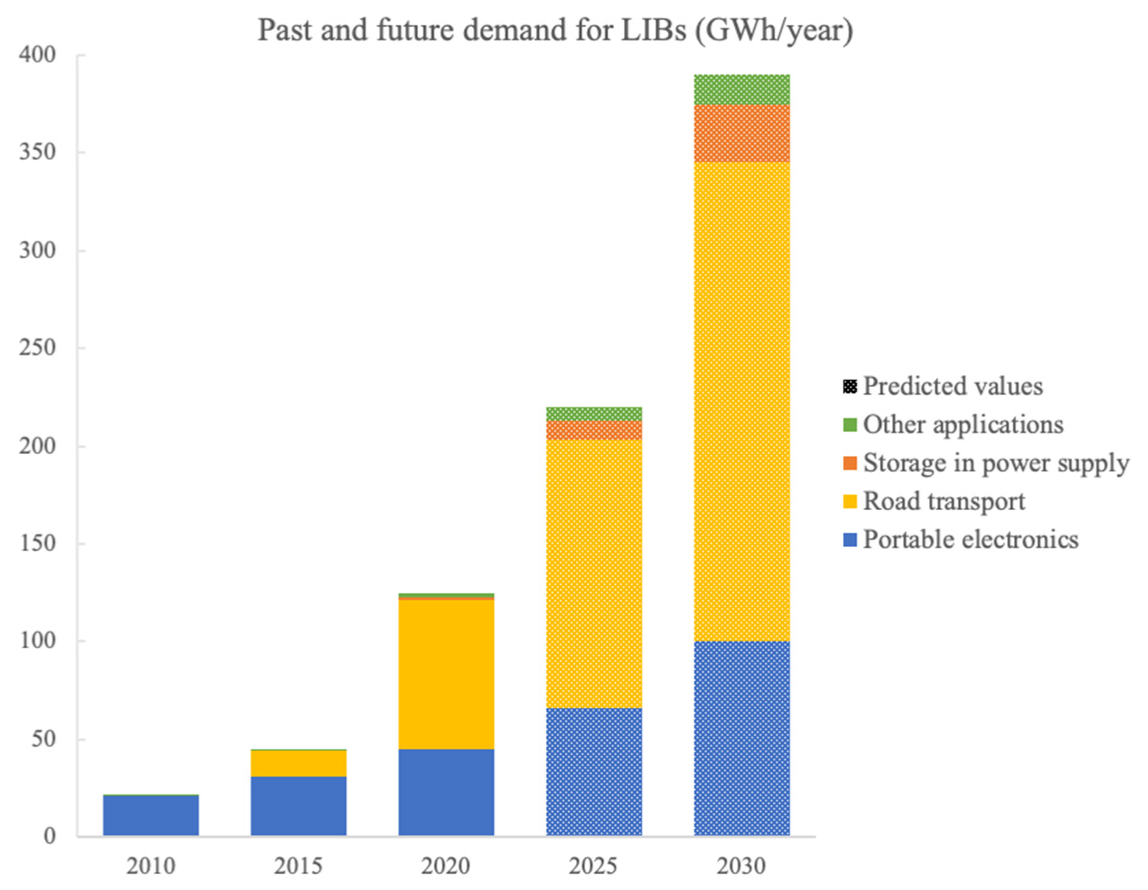
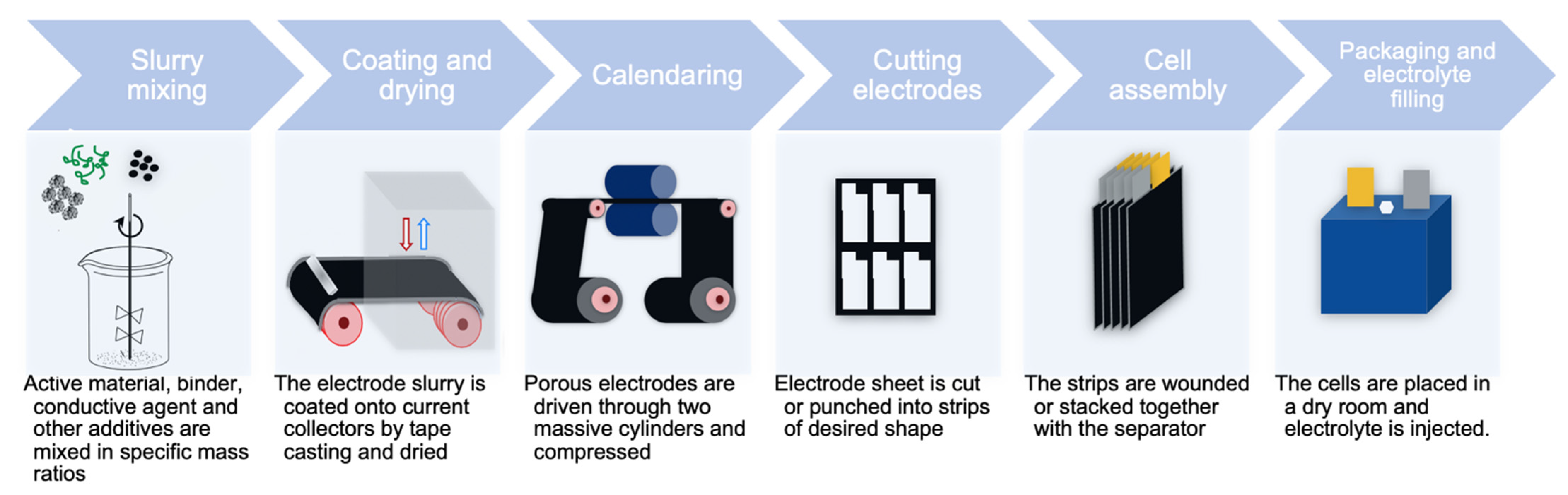
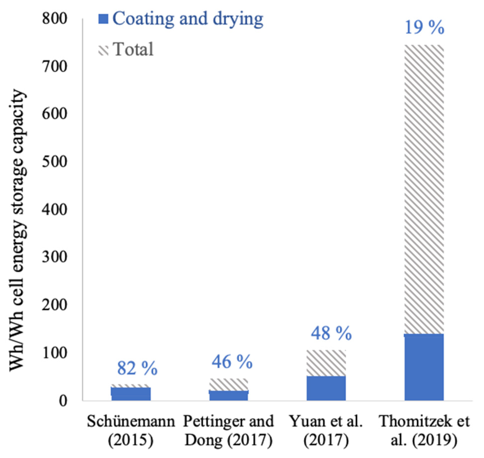
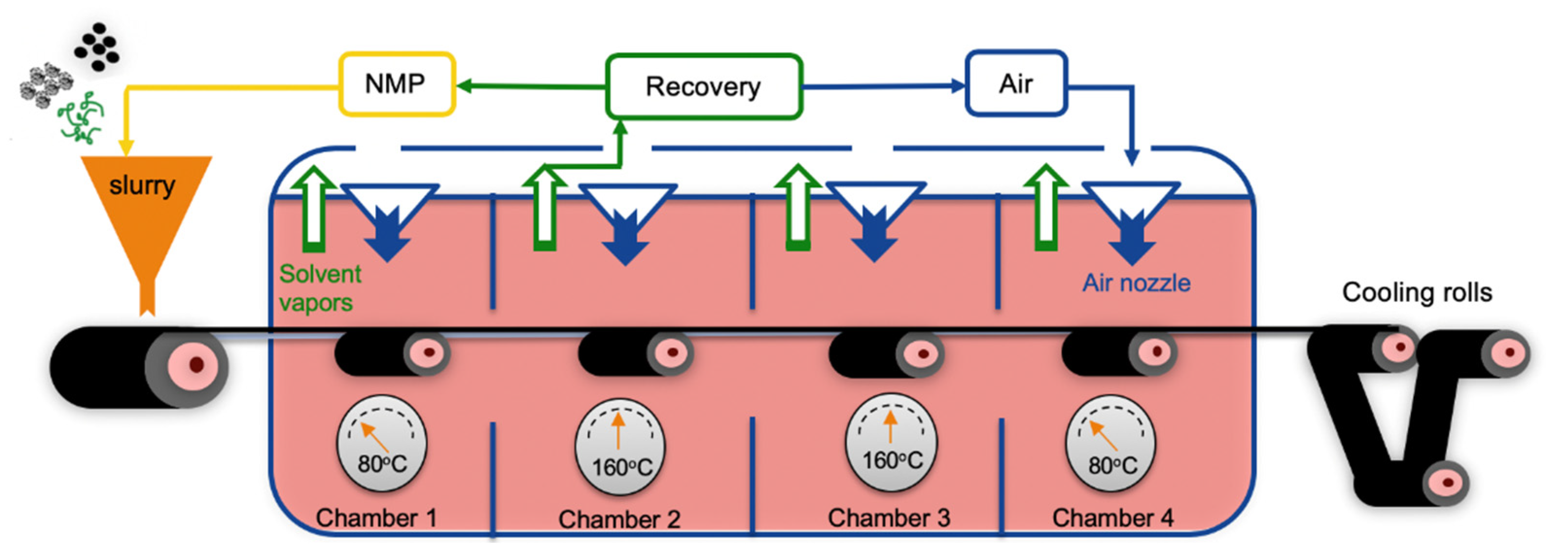
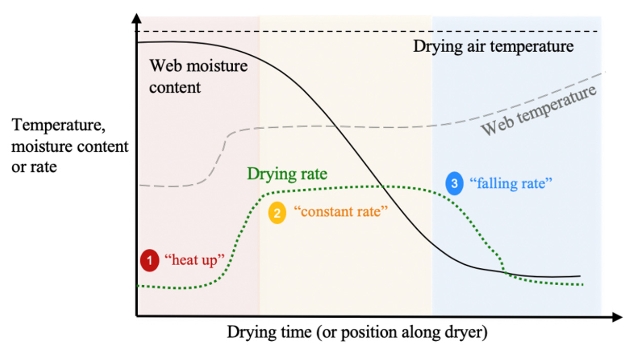
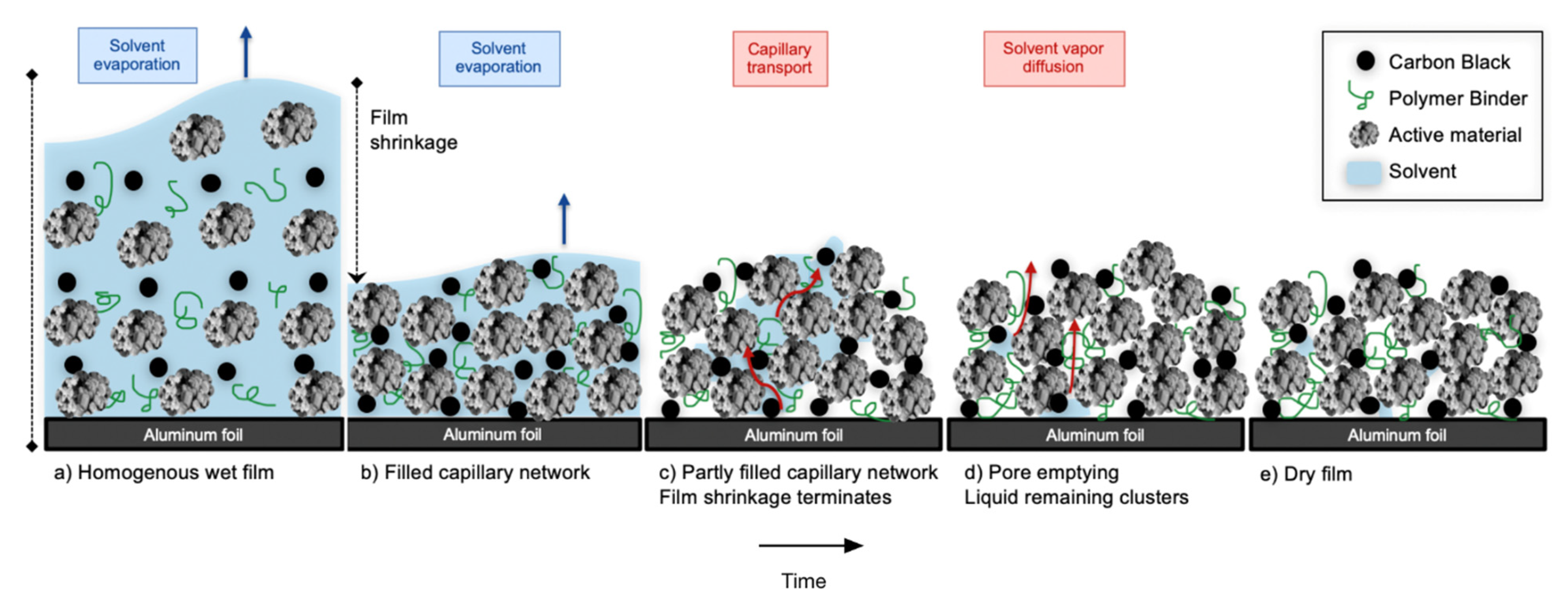
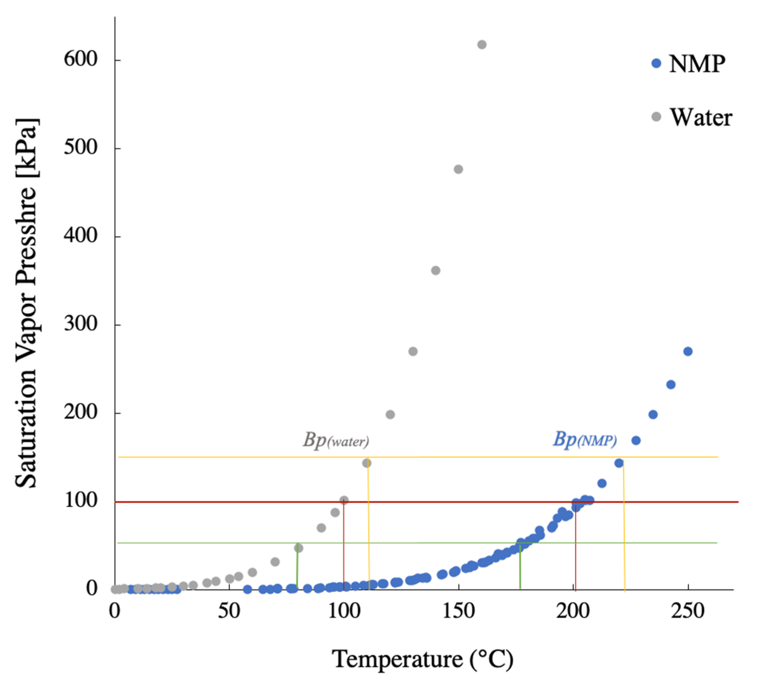
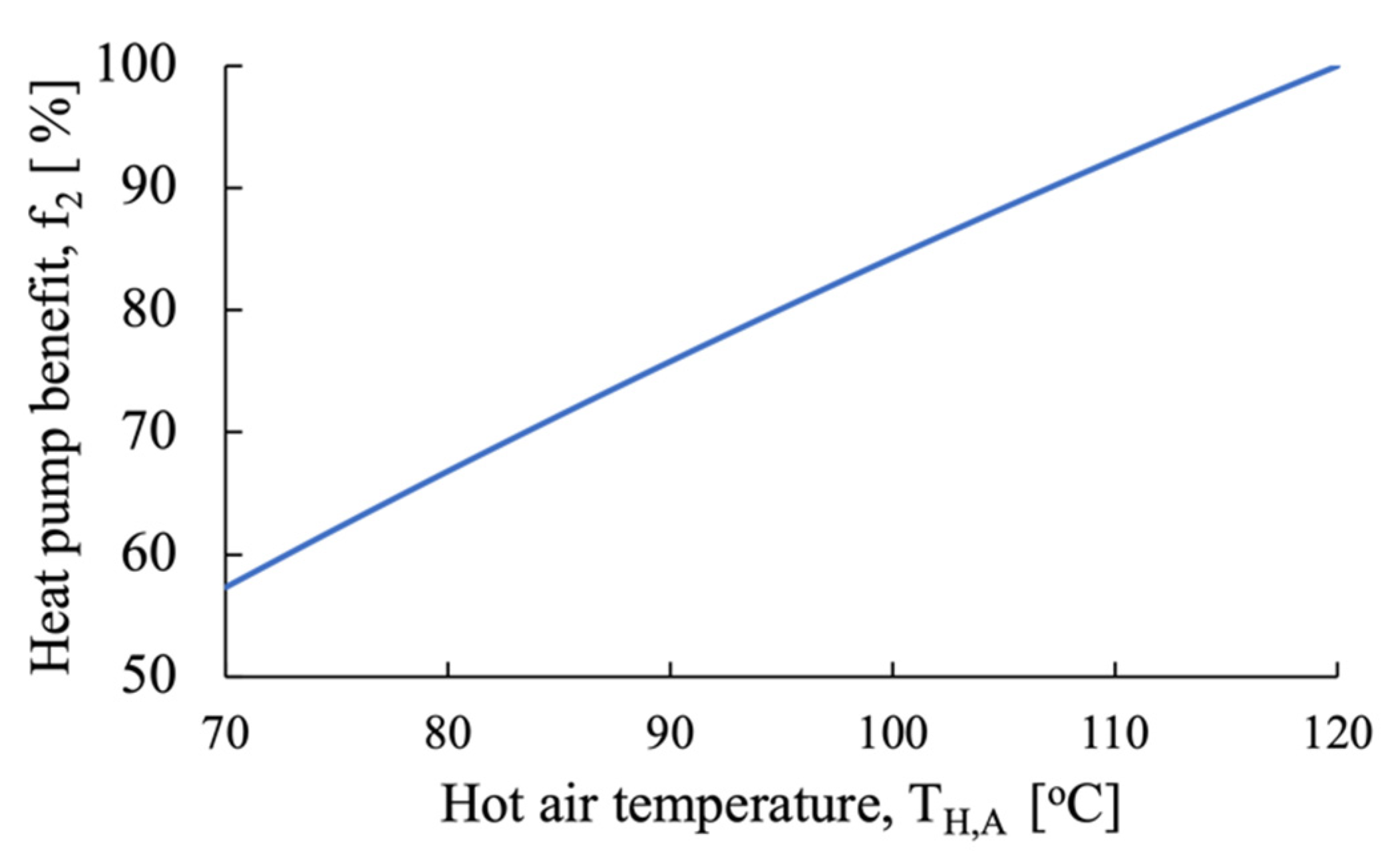
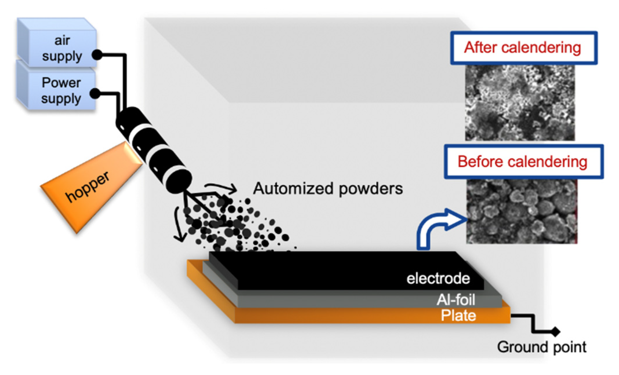
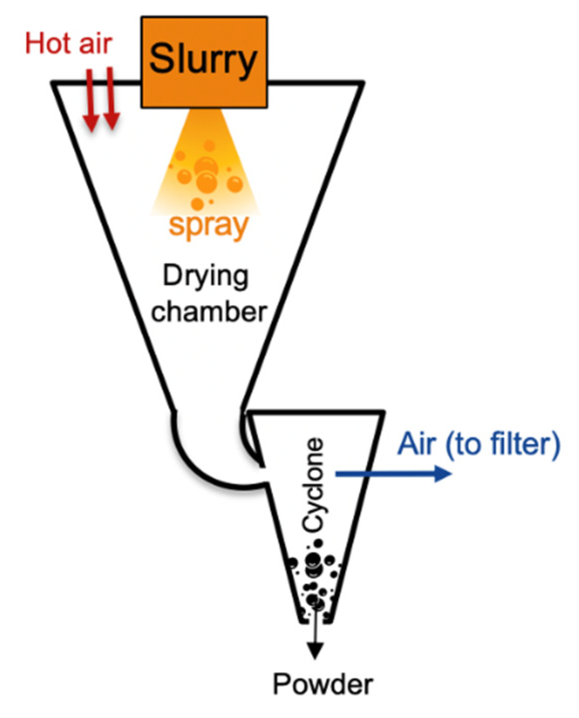
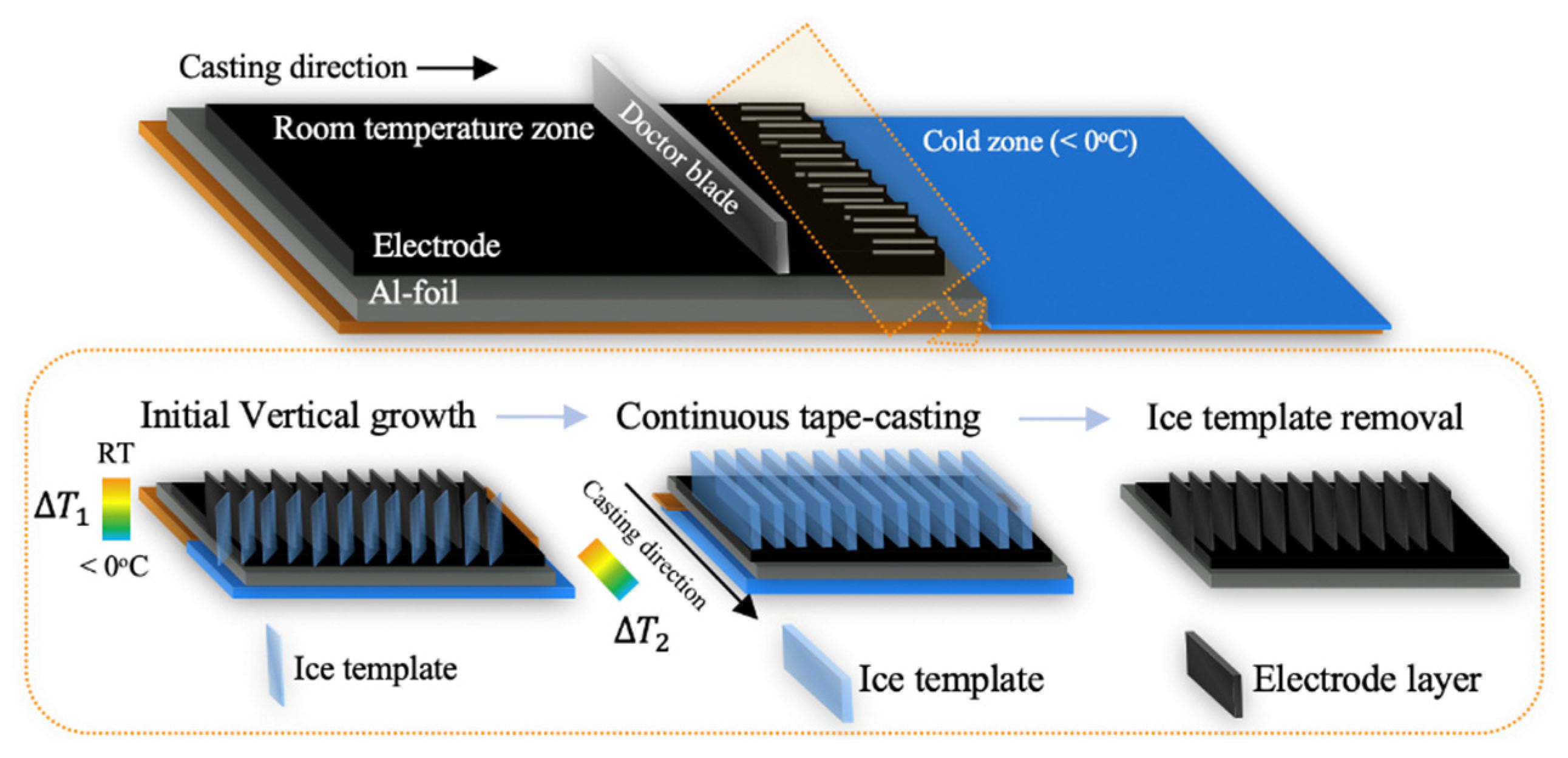
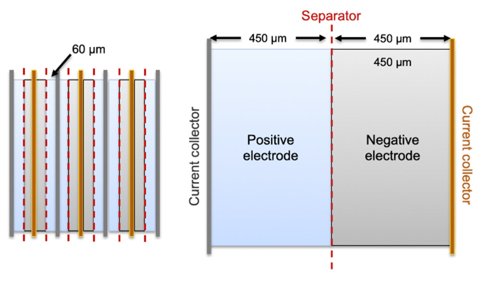
Table 1.
The fundamental properties that should be considered for the three main processing steps in electrode production, including slurry mixing, coating and drying, and the final electrochemical performance [40].
Table 1.
The fundamental properties that should be considered for the three main processing steps in electrode production, including slurry mixing, coating and drying, and the final electrochemical performance [40].
| Slurry Suspension | Dry Coated Electrode | Electrode Battery Performance |
|---|---|---|
| Homogeneity | Adhesion and particle cohesion | Low voltage, capacity, impedance variation |
| Rheology | Mechanical strength/flexibility | Uniform current density |
| Agglomeration of carbon black | Porosity | High efficiency, power and energy density |
| Tortuosity | Lifetime and cycle stability, safety |
Table 2.
Alternative binders for Li-ion batteries (LIB) electrode materials and their chemical formula, processability (water and/or ethanol processable), chemical composition (F-free), and natural available bio-polymers and derivatives [53].
Table 2.
Alternative binders for Li-ion batteries (LIB) electrode materials and their chemical formula, processability (water and/or ethanol processable), chemical composition (F-free), and natural available bio-polymers and derivatives [53].
| Binder | Formula | Water or Ethanol | F-Free | Biopolymers and Derivatives | Reference |
|---|---|---|---|---|---|
| Fluoro acrylic polymer (TRD 2020a) |  | x | [63,64] | ||
| Poly tetrafluoro ethylene (PTFE) | x | [65] | |||
| Poly vinylidene fluoride (PVDF) |  | [66,67,68,69,70,71,72,73] | |||
| Poly acrylates (PAA, PMA, PBA, PVA, PAN) |  | x | x | [74,75,76,77] | |
| Aliphatic polymers (PE, Polyisoprene, PVP, PVB) |  | x | x | [78] | |
| Aromatic polymers (PS, PU, SBR) |  | x | x | [79,80] | |
| Oligo- and polysaccharides (CMC, chitosan, alginate, pectin, amylose, starch, gums, lignin) |  | x | x | x | [64,70,81,82,83,84] |
| Proteins (gelatine, caseinate) | x | x | x | [85] |
Table 3.
Chemical and physical properties of different solvents for electrode slurry mixing [95,96] at T = 20 oC.
| Solvent | Melting Point (°C) | Boiling Point (°C) | Dipole Moment | Dielectric Constant | Density (g/cm3) | Viscosity (10−3 Pa s) | Flashpoint (°C) |
|---|---|---|---|---|---|---|---|
| Water | 0 | 100 | 1.9 | 80.1 | 1 | 0.89 | N/A |
| N-Methyl-2-pyrrolidone (NMP) | −24 | 202 | 4.1 | 32 | 1.033 | 1.85 | 96.67 |
| Dimethylformamide (DMF) | −61 | 153 | 3.8 | 37 | 0.944 | 0.80 | 58 |
| Dimethylacetamide (DMAC) | −20 | 166 | 3.7 | 38 | 0.942 | 2.14 | 63 |
| Dimethyl sulfoxide (DMSO) | 18.4 | 189 | 3.9 | 47 | 1.092 | 2.00 | 95 |
Table 4.
A summary of the research for aqueous processing of cathode materials with various binders.
Table 4.
A summary of the research for aqueous processing of cathode materials with various binders.
| Active Material | Variable (Binder or Solvent) | Investigated | Results (Initial Discharge Capacity (mAh/g), Capacity Retention (%)) | Reference |
|---|---|---|---|---|
| LFP | CMC | Dispersion properties of PAA | LFP cathode with CMC and CMC/PAA: 150 mAh/g, 50% after 35 cycles. LFP slurry viscosity: 135 mPa s (with 1.6% CMC and 0.4% PAA) and 70 mPa s (with 2% CMC). | Lee et al. [75] 2008 |
| PAA binder (water) and PVDF (NMP) | PAA as binder | PAA/aqueous: 134.4 mAh/g, 98.8% after 50 cycles. PVDF/NMP: 125.6 mAh/g, 94.9%. | Cai et al. [99] 2009 | |
| Polybutyl acrylate (PBA) latex + SCMC | Carbon-coated LFP and PSSA dispersant | 2 wt% PSSA: 144 mAh/g, >99% after 50 cycles. The PSSA free: 140 mAh/g, 98%. | Li et al. [100] 2010 | |
| SBR + SCMC | Dispersion effect of sequenced mixing of SCMC, SBRand LFP | SCMC mixed with LFP prior to SBR: 130 mAh/g, 95%. Simultaneous mixing of dry components: 121 mAh/g, 72%. | Li et al. [80] 2012 | |
| Xanthan gum | Examined the effect of PEI dispersant | Slurry with 2 wt% PEI: 165 mAh/g after 5 cycles at 0.2 C. | Li et al. [101] 2012 Li et al. [102] 2013 | |
| SBR + SCMC | Carbon coating quality LFP and gelation effect | C-LFP (1.07 wt% C) had the strongest gelation effect and 131 mAh/g at 1 C. C-LFP (2 wt% C) 140 mAh/g. | Tsai et al. [103] 2013 Tsai et al. [104] 2016 | |
| CMC | Gelation effect caused by -OH and -COO− on CMC, by testing two binders PVA (-OH) and PAA (-COO−). | Both -OH and -COOH created a H-bonding. The -COO− stabilised the slurry. | Li et al. [105] 2017 | |
| LFP and graphite | Lignin and PVDF | Lignin with PEG pre-treatment | 148 (lignin) and 305 mAh/g (graphite) at 0.1 C | Lu et al. [89] 2016 |
| LTO and NMC111 | CMC, guar gum (GG) or pectin | pH control:PA | Pectin, GG, and CMC (with PA): 174, 172, and 167 mAh/g at 1 C after 40 cycles. CMC without PA: 157 mAh/g. Full cells (NMC111/LTO) with CMC and PA: ~120 mAh/g after 190 cycles at 1 C. | Carvalho et al. [92] 2016 |
| Al-LTO | PTFE, PVA, and PVDF | Binders for AI-doped LTO electrodes | PVDF: 110 mAh/g PVA and PFTE: ~60 mAh/g | Priyono et al. [106] 2019 |
| LCO | Na-CMC + SBR (water) and PVDF (NMP) | Binder distributions | Less homogeneity in NMP-based slurry, but higher adhesion strength (569.6 g/cm) than water-based (258.3 g/cm). Both: 130 mAh/g at 0.2 C. | Li et al. [107] 2011 |
| NMC111 | CMC + TRD202A + Na-CMC | Reology affected different contents of binders, CA and liquid. | 3 wt% CB, 2 wt% Na-CMC, and 3 wt% TRD202A (21 vol% solid content) yielded proper flow behaviour. 135 (NMP) vs 125 mAh/g (water) after 50 cycles at 0.2 C. | Çetinel et al. [108] 2014 |
| CMC and PVDF | Coated-Al current collector (C-Al/CMC) compared to non-coated (Al/PVDF) | 151 (C-Al foil/CMC), 153 (Al/PVDF), and 131 (Al/CMC) mAh/g, all ~83% after 50 cycles at 1C. | Doberdò et al. [67] 2014 | |
| Na-CMC | pH control: PA and formic acid (FA) | pH 9.5. All: ~150 mAh/g. 80% (no acid), 86% (1% FA), and 91% (1% PA) after 50 cycles at 1 C. | Loeffler et al. [109] 2016 | |
| Na-CMC, SBR and PVDF (water and NMP) | pH control: Al2O3 (4.6 wt%) and SiO2 (2 wt%) additives and large (12–15 µm) and small (5 µm) particle sizes. | Additives reduce pH to <11 and prevent Al-corrosion. At 1C: 120 mAh/g, Al2O3 (12–15 µm), 112 mAh/g SiO2 (5 µm). >150 mAh/g (NMP). | Memm et al. [110] 2018 | |
| CMC, TRD2020A | pH control: polyacrylic acid (PAA) | Best performance at pH 9–10, which is above the stability region of the Al foil. | Bauer et al. [111] 2019 | |
| NMC523 | CMC (Water) and PVDF (NMP) | Residual moisture | Ni produces carbonates on the electrode surface and water and hydroxyl groups at the particle surfaces. | Li et al. [112] 2016 |
| CMC + acrylic emulsion polymer | Surface tension reduction of water using IPA | Optimal water/IPA ratio of 80/20 wt%. | Du et al. [113] 2017 | |
| NMC111, NMC523, NMC622, NMC811, graphite | CMC (water) and PVDF (NMP) | pH control and water exposure of NMC powder. | NMC811 with excellent capacity retention (~70%), comparable to NMP-processed (~76%), after 1000 cycles in full pouch cells. | Wood et al. [114] 2020 |
| Li-Rich NMC | CMC and PVDF | Investigating binders | PVDF: 250 mAh/g, 60% after 200 cycles at 1 C. CMC: 210 mAh/g, 83%. (1C = 200 mA/g) | Li et al. [115] 2011 |
| SA, CMC, and PVDF | Investigating binders | All: > 240 mAh/g. SA: 91.8% after 100 cycles at 0.1 CMC: 82.1%, PVDF: 62.1% (1C = 300 mA/g) | Han et al. [116] 2014 | |
| Cellulose, sodium alginate, and TRD202A | pH control: PA | Avoided Al corrosion. | Kazzazi et al. [64] 2018 |
Table 5.
Type of mixers used for LIB slurry production.
| Pilot-line/Industrial Production | Lab-Scale |
|---|---|
| Planetary mixer | Ball mill |
| High-speed mixer | Magnetic stirrer |
| Universal type mixer | 3D mixers |
| Static mixer | Turbine stirrers |
| Extruder | |
| Dissolver |
Table 6.
Coating types for industry and laboratory scale.
| Scale | Industry | Laboratory |
|---|---|---|
| Type | Slot-die coater | Tape caster/doctor blade |
| Cell production [40] | Fully automated, continuous, and integrated process | Small scale, discontinuous process |
| Coating speed rate (m/min) [141,142] | 25 | 0 |
| Coating thickness accuracy (µm) | ±1 | ±2 |
| Coating thickness (µm) | 2–100 | 10–200 |
| Coating width (mm) | 1500 | 100–200 |
Table 7.
The electrode performance of various electrodes made with different thicknesses and under different drying conditions.
Table 7.
The electrode performance of various electrodes made with different thicknesses and under different drying conditions.
| Electrode Chemistry (Solvent) | Thickness (μm) | Drying Conditions | Performance | Reference |
|---|---|---|---|---|
| Cathode: NMC532 | 158 | 70–135 °C 5–35 m/s | Cracking of electrodes at a high drying rates and temperature over 75 °C | Susarla et al. [97] 2018 |
| Anodes: Graphite, CMC, SBR (water) | 150 | 150 °C 2 m/s | Higher SBR concentration on electrode surface | Hagiwara et al. [169] 2014 |
| Anodes: Graphite, PVDF (NMP) | 78 | 76.5 °C High drying rate (HDR) Low drying rate (LDR) | HDR sample showed an additional loss of discharge capacity as a result of incomplete charging. 86 mAh/g vs. 115 mAh/g for LDR (3.0 °C) | Jaiser et al. [165] 2016 |
| GMS G10, PVDF, CB (NMP) | 2.7–12.0 mg/cm2 | 80, 110 and 130 °C Nozzle outlet velocity 17 m/s | High electrode resistance (over 0.25 Ω) for thickness over 10.5 mg/cm2 and drying temperature over 110 °C. Thickness does not affect electrical esistance so much, when drying at 80 °C | Westphal et al. [171] 2018 |
| Cathode: C-LiFePO4, CB, PVDF | 65 | 60–120 °C No air circulation | The best discharge capacity for drying at 80 °C: 156.4, 148.1, 124.4 mAh/g at 0.1, 0.5, and 2.0 C | Gören et al. [172] 2016 |
| Cathode: NMC111 (water) | 200, 300, 400 | 20, 45, 70 °C Vacuum oven. | Best performance drying at 20 °C, 200 μm, 132mAh/g at 0.1 C. Gradually decreasing with increasing of drying temperature and thickness | Rollag et al. [79] 2019 |
| Anode: Graphite SMEA CB, CMC, SBR (water) | 70–512 | 31–49 °C | No cracking was observed at drying rate below 3 g/m2 s for thick samples. | Kumberg et al. [140] 2019 |
Table 8.
Some alternative electrode production techniques to conventional wet slurry production and convection drying. The active materials and solvents used are specified.
Table 8.
Some alternative electrode production techniques to conventional wet slurry production and convection drying. The active materials and solvents used are specified.
| Alternative Techniques to Wet Slurry Casting and Drying | Active Material (Solvent) | Reference |
|---|---|---|
| Electron beam curing | NMC532 (NMP) | Du et al. [187] 2016 |
| Spray-printing | LFP and LTO (water/IPA) | Lee et al. [188] 2019 |
| 3D printing | Flexible LFP and LTP (NMP) | Bao et al. [189] 2020 |
| Pulsed-laser deposition | Solid-state batteries with an LCO cathode | Shiraki et al. [190] 2014 |
| Spray-drying | Review of most cathode chemistries (ethanol, water, or alcohol) | Vertruyen et al. [57] 2018 |
| Freeze-casting/Freeze-drying | LFP (water) Mo-doped LTO NCA Sulphur/graphene oxide 3D printing LFP (water) Solid oxide fuel cells | Orlenius et al. [90] 2012 Ghadkolai et al. [191] 2017 Delattre et al. [157] 2018 Hwa et al. [192] 2019 Liu et al. [193] 2017 Du et al. [194] 2018 |
| Near-infrared drying or laser drying | Graphite anode and LFP (water) | Vedder et al. [195] 2019 Hawelka et al. [196] 2015 Pfleging et al. [197] 2017 Günther et al. [198] 2016 |
| Solvent-free methods | ||
| Dry pressed R2R manufacturing | Binder-free LFP with holey graphene (solvent-free). | Kirsch et al. [199] 2019 |
| Electrostatic spray deposition | LCO, NMC111, graphite (solvent free) Elaborated in Table 9 below. | Schälicke et al. [182] 2020 Wang et al. [68] 2019 Liu et al. [179] 2017 Al-Shroofy et al. [73] 2017 Ludwig et al. [181] 2017 Ludwig et al. [178] 2016 Hiroya et al. [77] 2015 |
Table 9.
Washing agents for the alternative removal of NMP.
| Washing Agent | Vapor Pressure (kPa) at 20 °C | Molecular Weight (g/mol) | Viscosity (mPa s) at 25 °C | Flash Point (°C) | Miscible in |
|---|---|---|---|---|---|
| Acetone | 24.60 | 58.08 | 0.295 | −20 | Water, benzene, diethylether, methanol, chloroform, ethanol |
| Ethanol (95%) | 5.95 | 46.07 | 1.095 | 15.5 | Water, ethylether, acetone, chloroform, Soluble in benzene |
Table 10.
An overview of research conducted on different electrodes manufactured using solvent-free methods such as EDS and R2R manufacturing. The slurry chemistry, cell type, porosity, thickness of the coated layer, and the final electrochemical performance are specified.
Table 10.
An overview of research conducted on different electrodes manufactured using solvent-free methods such as EDS and R2R manufacturing. The slurry chemistry, cell type, porosity, thickness of the coated layer, and the final electrochemical performance are specified.
| Active Material:Binder:Conductive Additive (Ratio) | Cell Type | Porosity (%) | Thickness (µm), Mass Loading (mg/cm2) or Area Capacity (mAh/cm2) | Electrochemical Performance (Initial Discharge Capacity (mAh/g), Capacity Retention (%)) | Investigated | Reference |
|---|---|---|---|---|---|---|
| Electrostatic spray deposition | ||||||
| LCO or NMC111:PVDF:CB (90:5:5) | Li half-cells (CR2025) | 30 | 40–130 (µm) | LCO dry: 114 mAh/g, 70% LCO wet: 115 mAh/g, 58%. after 50 cycles at 0.5 C between 2.5 and 4.2 V. NMC111 dry: 138 mAh/g, 87% NMC111 wet: 138 mAh/g, 84% after 50 cycles at 0.5 C between 2.8 and 4.3 V. | EDS and hot-rolling temperature. A higher mechanical strength (148.8 kPa) compared to wet processed electrodes (84.3 kPa) | Ludwig et al. [178] 2016 |
| LCO:PVDF:CB (98:1:1) | Full cell w/graphite anode | - | - | Dry: 127.8 mAh/g, 77% after 100 cycles at 0.5 C between 2.5 and 4.2 V Mechanical strength: 93.8 kPa. | EDS and hot rolling. The effect of low binder and CB content. | Ludwig et al. [181] 2017 |
| NMC111;PVDF:CB (19:1:1 wt. ratio) | Li half-cells | 31–41 | Wet (low loading): 7.65 mg/cm2 (32.6 µm) Wet (high loading): 14.27 mg/cm2 (52 µm) Dry: 10.07 mg/cm2 (40.5 µm) | Wet (low loading): 156 mAh/g, 60% Wet (high loading): 157 mAh/g, 65% Dry: 155 mAh/g, 80% after 300 cycles when cycled between 3.0 V and 4.3 V at 0.5 C. | EDS and rolling at room temperature. Compared dry processed electrodes to two wet processed electrodes of higher and lower mass loadings. | Al-Shroofy et al. [73] 2017 |
| NMC111:PVDF:CB (90:5:5) | Full cell w/graphite anode | 29–30 | Wet and dry: 55–56 µm (2.45 mAh/cm2) Dry: 100 (5.80 mAh/cm2), 150 (6.52 mAh/cm2) and 200 µm (9.11 mAh/cm2) | Dry (55 µm): 150 mAh/g, >80% Wet (55 µm): 145 mAh/g, 65% after 500 cycles at 0.5 C. Dry (55 µm): 120 mAh/g at 3 C. Dry (100, 150, 200 µm): <20 mAh/g at 3 C. For 0.2–3 C, the thin dry processed electrodes showed better rate performance than the thick. | EDS. Compared different thicknesses of dry coated electrodes to a wet processed electrode. | Liu et al. [179] 2017 |
| NMC111:PVDF:CB (90:5:5) | Li half-cells (coil-cell) | 31 | 59 µm (2.4 mAh/cm2) | Low molecular weight PVDF: 160 mAh/g at 0.2 C, 93% after 50 cycles at 0.5 C. At 5C: 16.7% High MW: 160 mAh/g at 0.2 C, 91% after 50 cycles at 0.5 C. At 5C: 50% Cycled between 3.0 and 4.3 V. | EDS and investigated the PVDF binder’s molecular weight. | Wang et al. [68] 2019 |
| Graphite:THV or FEP:CB (86:7:7) Graphite:PVDF:CB (85:10:5) | Li half-cells (Three electrode cells) | - | Wet PVDF: 3 mAh/cm2 Dry THV: 3.5 mAh/cm2 (11 mg/cm2) Dry FEP: 2.7 mAh/cm2 | All dry powder-coated anodes: 370 mAh/g (99% of the theoretical capacity) and >345 mAh/g. after 50 cycles at 0.5 C when cycled between 0.02 and 1.5 V. | Used a modified fluidised bed system followed by hot-pressing. A two-step mixing method: first mix binders and CB into a matrix, and then add graphite. (Mixing rates: 30 m/s or 40 m/s) | Schälicke et al. [182] 2020 |
| Dry roll-to-roll technology | ||||||
| LFP and holey graphene (1:1 wt ratio) | Li half-cells (CR2032) | - | 340 µm (hydraulic pressure of 20 MPa) (11.6mg/cm2) | 163 mAh/g, 89% after 200 cycles at 0.2 C between 2.6 and 3.7 V. | Dry pressed binderless materials. at 500, 200, and 20 MPa). The LFP showed no structural changes and comparable rate capability to the traditionally produced LFP. | Kirsch et al. [199] 2019 |
| NMC111, NMC622, NMC811, NCA, LFP, LTO, graphite, sulfur/carbon and silicon composite. | Full cells w/graphite anode (pouch cell) | - | NMC111/graphite: 27 mg/ cm2 (4 mAh/cm2) and 36 mg/cm2 (5 mAh/ cm2) | Dry NMC111/graphite (4mAh/cm2): 90% after 2000 cycles at 0.5C charge/1 C between 2.7 and 4.2 V. Dry and wet NMC111/graphite (5 mAh/cm2): Identical at 0.1 C (105 mAh). At 0.5 C the dry and wet had 91% and 70% capacity retention, respectively. Between 2.8 and 4.2 V. | By Maxwell technologies. The dry processed electrodes obtained higher rate capabilities than wet processed electrodes. | Duong and Shin et al. [180] 2018 |
Publisher’s Note: MDPI stays neutral with regard to jurisdictional claims in published maps and institutional affiliations. |
© 2021 by the authors. Licensee MDPI, Basel, Switzerland. This article is an open access article distributed under the terms and conditions of the Creative Commons Attribution (CC BY) license (http://creativecommons.org/licenses/by/4.0/).
Share and Cite
MDPI and ACS Style
Bryntesen, S.N.; Strømman, A.H.; Tolstorebrov, I.; Shearing, P.R.; Lamb, J.J.; Stokke Burheim, O. Opportunities for the State-of-the-Art Production of LIB Electrodes—A Review. Energies 2021, 14, 1406. https://doi.org/10.3390/en14051406
AMA Style
Bryntesen SN, Strømman AH, Tolstorebrov I, Shearing PR, Lamb JJ, Stokke Burheim O. Opportunities for the State-of-the-Art Production of LIB Electrodes—A Review. Energies. 2021; 14(5):1406. https://doi.org/10.3390/en14051406
Chicago/Turabian StyleBryntesen, Silje Nornes, Anders Hammer Strømman, Ignat Tolstorebrov, Paul R. Shearing, Jacob J. Lamb, and Odne Stokke Burheim. 2021. "Opportunities for the State-of-the-Art Production of LIB Electrodes—A Review" Energies 14, no. 5: 1406. https://doi.org/10.3390/en14051406
Note that from the first issue of 2016, this journal uses article numbers instead of page numbers. See further details here.