
Solar Thermochemical Green Fuels Production: A Review of Biomass Pyro-Gasification, Solar Reactor Concepts and Modelling Methods


1
Processes, Materials and Solar Energy Laboratory, PROMES-CNRS, 7 Rue du Four Solaire, 66120 Font-Romeu, France
2
CEA-LITEN Solar and Thermodynamic Systems Laboratory (L2ST), F-38054 Grenoble, France
*
Author to whom correspondence should be addressed.
Energies 2021, 14(5), 1494; https://doi.org/10.3390/en14051494
Submission received: 5 February 2021
/
Revised: 1 March 2021
/
Accepted: 3 March 2021
/
Published: 9 March 2021
(This article belongs to the Special Issue Thermal Analysis of Biomass Energy Production Process)
Abstract
:This paper addresses the solar thermochemical conversion of biomass or waste feedstocks based on pyro-gasification for the clean production of high-value and energy-intensive fuels. The utilization of solar energy for supplying the required process heat is attractive to lower the dependence of gasification processes on conventional energy resources and to reduce emissions of CO2 and other pollutants for the production of high-value chemical synthetic fuels (syngas). Using concentrated solar energy to drive the endothermal reactions further allows producing more syngas with a higher gas quality, since it has not been contaminated by combustion products, while saving biomass resources. The solar-driven process is thus a sustainable and promising alternative route, enabling syngas yield enhancement and CO2 mitigation, thereby potentially outperforming the performance of conventional processes for syngas production. This review presents relevant research studies in the field and provides the scientific/technical knowledge and background necessary to address the different aspects of the solar gasification process. An overview of the available solar concentrating technologies and their performance metrics is first introduced. The solar gasifier concepts and designs that were studied from lab to industrial scale are presented, along with their main benefits and limitations. The different management strategies proposed to deal with solar energy variations are also outlined, as well as the major pilot-scale applications and large-scale system level simulations. A specific emphasis is provided on the spouted bed technology that appears promising for the gasification process. Finally, the main modeling approaches of pyro-gasification and kinetics for simulation of gasifiers are described. This study thus provides a detailed overview of the efforts made to enhance the thermochemical performance of solar-assisted biomass gasification for synthetic fuel production.
1. Introduction
Gasification reactors have been developed and commercially deployed on the market for more than a century, with current applications in chemicals, liquid fuels, and power generation. Such industrial reactors rely on partial combustion of the injected feedstock to deliver the necessary energy required to activate and carry out the strongly endothermic gasification reactions. This leads to a reduction of the overall material conversion yield and penalizes the process energy conversion efficiency. The combination of thermochemical biomass gasification with concentrated solar energy is advantageous, since it offers the possibility to take benefits of both resources. Indeed, all the biomass resource can be converted into a mixture of hydrogen and carbon monoxide (syngas), since high-temperature solar heat is advantageously exploited to provide the gasification reaction enthalpy. This is due to the fact that all the required energy for reactions is supplied by solar energy; thus, the burning of part of the feedstock can be avoided, which saves resources and avoids products’ contamination with combustion by-products. Using concentrated solar energy as the external process heat source to drive the endothermal reactions thus allows saving biomass resources and producing more syngas output per unit mass of feedstock, with a higher syngas quality (since it is not contaminated by combustion products). Solar-driven gasification promotes the utilization of biomass while it is an efficient way to store intermittent solar energy in the form of renewable, dispatchable, and storable solar fuels.
Several experimental studies addressing the allothermal solar gasification have been conducted to demonstrate the feasibility and efficiency of the process at laboratory scale [1,2]. A first solar spouted bed reactor was built and experimentally tested at the CNRS-PROMES solar furnace in Odeillo in France for the continuous steam conversion of millimetric beech wood particles at temperatures up to 1400 °C [2]. Although the experimental tests on wood validated the design and demonstrated the viability of the solar process at laboratory scale, there are still a number of obstacles and challenges to address before the solar gasification process can be scaled up for industrial application. Some examples of current issues to be addressed can be highlighted as follows:
- The biomass particles/gas flow hydrodynamics and its interaction with chemistry and radiation (coupled heat and mass transfer) need to be optimized.
- The variable nature of solar energy and its impact on the reactor operation has to be assessed for continuous process operation and stable syngas production, which requires the harnessing of intermittency (day/night cycle) and diurnal solar fluctuations (daily/seasonal variations and meteorological contingencies).
- The ability of the solar reactor design to convert varied loads and heterogeneous compositions (e.g., biomass, waste, solid waste fuels, etc.) needs to be evaluated.
- The technical feasibility of the solar process at large scale and its economic/financial viability need to be investigated.
This review is devoted to a literature survey, which presents relevant research studies in the field and provides the scientific/technical knowledge and background necessary to deal with the different aspects of the solar gasification process. The global purpose of the review is to focus on the various concepts required for the development of solar-assisted biomass gasification. The solar gasifier concepts that were studied from lab to industrial scale are presented. The survey further aims at clarifying the state-of-the-art, determining the scientific and technological challenges, and defining the main research areas to be pursued. It is organized as follows: Section 2 presents an overview about concentrated solar energy, current solar energy systems, and their performance metrics. Section 3 is organized in three parts; the first part presents the main previously studied reactor designs, their advantages, and limitations. The second part outlines the different management strategies proposed to deal with solar energy variations. The third part focuses on the scale-up of solar gasifiers. It presents a summary of pilot scale projects and recaps major large-scale system level simulations that couple the solar gasification concept with various energy and chemical processes. Section 4 introduces spouted beds technology that appears promising for the gasification process; it describes its main features and presents the previously studied spouted bed gasifiers. Finally, Section 5 tackles the main modeling approaches of pyrolysis and gasification with emphasis on relevant models that can be used in CFD (Computational Fluid Dynamics) simulation of gasifiers.
2. Concentrated Solar Energy
2.1. Overview
As solar energy is diluted, the direct solar flux received on the Earth’s surface can hardly exceed 1000 W.m−2. To capture this energy and transform it into heat, specific solar devices should be used. There are two main solar technologies that valorize the solar radiant energy into heat: flat-plate technologies [3] and concentrators [4]. The first kind is often used for domestic heating/air conditioning and in some cases, in industry for process heat generation. Due to excessive heat losses, these systems barely achieve 100–200 °C. Solar concentrators enable the delivery of energy at high temperature, which makes them crucial for many industrial and energy applications. Such technologies are based on the use of a receiver whose surface aperture is minimized (to reduce the thermal radiative losses) and optical systems, which collect and concentrate sunlight towards the receiver. There are two main areas of interest in concentrated solar energy: chemicals and power generation. Currently, power generation by concentrated solar energy (commonly referred to as concentrated solar power or CSP) is the most mature. CSP plants use the sunlight to heat a heat transfer fluid (HTF); the latter exchanges energy with water, which becomes superheated and drives a conventional steam turbine-generator. Very often, to smooth out the energy delivery on cloudy and nocturnal hours, CSP plants are also equipped with thermal energy storage (TES) units making use of an energy storage medium such as molten salt mixtures to store for several hours (e.g., 6–10 h for a majority of active CSP projects) midday surplus sensible energy [5].
2.2. CSP in the World
CSP has been commercially available since 1984, and it reached a world electrical production capacity of 5500 MW in 2018 [6]. Spain and USA are today the world leading countries in CSP, holding around 66% of the total power production capacity. Additionally, more than one third of major CSP projects are either under development or under construction, especially in China, Chile, Australia, South Africa, and the Middle East and North Africa (MENA) region, which denotes a growing interest in CSP worldwide. The commercial viability of the plants depends on a large number of criteria, including the location of the power plants. In fact, solar concentration concerns exclusively the direct component of sunlight, which needs to be as high as possible. The best locations for CSP plants are therefore corresponding to limited areas on Earth, which should guarantee a high level of DNI (direct normal irradiance) all year round. The DLR (Deutsches Zentrum fur Luft-under Raumfahrt) drew a map of potential sites, as identified within the EU-project REACCESS [7], which are auspicious for CSP. The role of Earth observation satellites in maximizing the efficiency of renewable energy production is also relevant. Satellites mapping can be helpful to identify suitable plant locations and to provide some specific data (e.g., solar irradiance, wind speed, precipitation, climate conditions, etc.) [8].
These sites are characterized by a DNI higher than 2000 kWh.m−2.year−1, by a large open area (as flat as possible) with no property nearby, and by the presence of a power distribution network and a large supply of water. Note that under these conditions, only 1% of the Sahara desert area is able to satisfy today’s world electricity demand [9].
2.3. Concentrating Solar Systems
Four CSP technologies are generally accepted and commercially available for the production of electricity (Figure 1). Each technology has its own concentration level, which is expressed by the concentration ratio (C). From an energetic point of view, this ratio can be defined as the solar radiation hitting the receiver over the flux entering the collector. However, the flux on the receiver is neither uniformly distributed, nor easily measurable. Additionally, it varies during the day. For this reason, geometrical concentration was introduced. This parameter is more convenient for practical engineering applications, as it depends on the geometry of the technology as manufactured. It is expressed as the ratio between the concentrator aperture surface and the surface of the receiver aperture.
The maximum temperature level delivered by a CSP technology depends above all on this parameter C. Parabolic trough (PT) and linear Fresnel (LF) reflectors (Figure 1a,b) are one-axis tracking and line-focusing technologies. Their operating temperature range is 250–400 °C with concentration ratios of about 50–100. Central receivers (i.e., tower configuration, Figure 1c) and parabolic dish concentrators (Figure 1d) are two-axis tracking and point-focusing technologies, and their concentration ratios can easily reach 1000 at the expense of a greater cost and complexity. This allows reaching higher temperatures at the receiver, which improves the solar-to-electric (STE) efficiency and reduces the energy costs [10,11,12]. In the four configurations, the concentration ratio (and thus the receiver temperature) can be increased by adding further optical components such as 2D and 3D CPCs (compounds parabolic collectors) [13].
Even if PT technologies dominated the market during the last two decades, tower plants show an increasing interest today. In fact, the total power capacity of tower plants under construction or development is twice that of PTs [14]. LF reflectors’ and dish collectors’ utilization remains marginal, except in some small projects worldwide.
The solar tower configuration gains attractiveness and shows a high potential for coupling with high temperature thermochemical processes at large scale [12,15]. This configuration presents various possible arrangements depending on the heliostats (i.e., tracking mirrors) layout and on the central receiver design/location (Figure 2).
Figure 2a shows an external receiver with an aperture receiving radiation all around the circumference. This concept is used in a number of large-capacity tower plants such as Noor in Morocco and Ivanpah in California. Figure 2b depicts a cavity receiver mounted on the top of a tower with a polar heliostat field. The receiver is an insulated enclosure with an aperture irradiated from one side of the tower only. The PS10 plant near Seville in Spain is the first ever built commercial solar tower plant, and it is based on this principle.
The third possible configuration shown in Figure 2c makes use of the Cassegrain optical arrangement borrowed from telescopes. The cavity receiver is set on the ground and a secondary reflector at the top of the tower redirects the impinging light towards the receiver. This significantly reduces the weight and the cost of the tower, which thus supports only the secondary reflecting component [16]. For instance, a commercial plant making use of beam-down/reflector technology was recently built in China by BCP Solar Technology (XinChen CSP).
2.4. Performance Metrics
Energy losses in CSP plants are basically of two types: optical and thermodynamic. The optical losses are due to different factors, which vary with the mirrors properties, the plant location, and the period of the year. These losses are generally classified as follows: (i) the reflection losses are due to the non-perfect specular reflection on the mirrors surface, (ii) the cosine losses are due to the angle between the incident solar rays and the mirrors normal vector, (iii) the shading losses are caused by shading induced by some solar components relative to others (e.g., solar tower/heliostat field), (iv) the blockage losses occur when some reflectors block part of the reflected solar rays especially at low sun elevation angles, (v) the spillage losses are due to a proportion of irradiation that misses the receiver aperture because of tracking inaccuracies and mirrors shape defects, and (vi) the attenuation losses are due to atmospheric scattering/absorption of radiation, especially in large tower plants where the collector/receiver distance is high. With this in mind, the plant optical efficiency (ηopt) can be written as the product of each efficiency factor, as depicted in Equation (1).
Accordingly, the optical efficiency of a solar plant is neither a fixed nor a predetermined value. It varies and decreases significantly during the day and throughout the years due to aggressive and repetitive stress factors such as temperature, humidity, saline mist, wind, and sand storms [17]. The maintenance of mirrors as well as their frequent washing is essential to guarantee good conversion efficiency in the long-term. Globally, the lifetime of solar mirrors is about 25–30 years [18].
The overall CSP plant’s efficiency (solar-to-electrical) results from the combination of the optical efficiency, the receiver absorption efficiency, and the thermodynamic efficiency of the cycle. Assuming that the solar receiver behaves like a grey body and that it only exchanges heat by radiation with outside, the efficiency of a solar receiver (or absorption efficiency) brought to the Trec temperature can be written as a function of the geometric concentration C = Amirrors/Arec, the optical efficiency ηopt, the DNI, and the receiver radiative properties (α and ε are the receiver absorptivity and emissivity) (Equation (2)).
where Qabs and Qrec represent the absorbed solar power and the solar power attaining the receiver, Arec is the receiver surface (receiving the radiation), and DNI (W.m−2) is the direct normal irradiance, a measured solar data characterizing the flux received on Earth’s surface, which is perpendicular to sunlight. σrad is the Stefan–Boltzmann constant (~5.67.10−8 W.m−2.K−4).
The theoretical (maximum) thermal-to-electrical efficiency is given by the Carnot efficiency, Equation (3). Accordingly, the overall ideal plant efficiency is given by Equation (4), where Tamb and Trec are the lower and upper temperature limits of the Carnot engine.
For thermochemical applications, the primary goal is not to produce electricity, so the coupling with a thermodynamic cycle is generally not considered. The energy efficiency of the solar system is therefore limited only by the receiver efficiency (Equation (2)).
The exergy efficiency of thermochemical processes is another interesting parameter to quantify because it gives an indication of how well solar energy is converted into chemical energy. It is defined as the ratio of the maximum work that may be extracted from output products to the solar power input that drives the process. By applying the second principle of thermodynamics, the exergy efficiency of a solar thermochemical process can be expressed in a similar way by Equation (4) [19].
Figure 3 shows the absorption, the ideal CSP, and the Carnot efficiencies of a black body receiver operating at different temperatures and concentration ratios [20]. It can be observed that the absorption efficiency is increased by higher concentration ratios. Moreover, for a given concentration ratio, the absorption efficiency decreases drastically with temperature. Indeed, the thermal radiative losses evolve with temperature to the power of 4. Furthermore, the exergy efficiency curves show that there is an optimum temperature at each concentration ratio that maximizes the conversion efficiency. Above this temperature, re-radiation losses become higher.
3. Solar Gasification
Various innovative concepts were developed to take advantage of solar energy and convert this renewable resource into added-value chemical products. Powered either by solar electricity, solar photons, or solar heat, these concepts were classified in three groups [19]: the electrochemical group converts electric power into chemicals using an electrolytic process; the photochemical and photobiological group uses the solar photons for photochemical and biological processes; the thermochemical group uses high temperature solar heat to drive endothermic chemical reactions. The latter is of particular interest, as it offers thermodynamic advantages. In this regard, a number of pioneering processes using either water, carbon dioxide, or carbonaceous resources or any combination of the three as a primary feedstock for hydrogen and syngas (i.e., a mixture of CO and H2) generation were investigated [2,15]. Within this scope, the gasification process has shown great promise and has been the subject of several research studies across the globe [1,21].
The gasification process is endothermic, and consists in converting biomass into a variety of marketable and added-value products. When based on solar energy utilization, solar gasification is a suitable means to potentially ensure the complete thermochemical conversion of biomass into syngas. Accordingly, solar energy is converted and stored in the form of gaseous species mainly composed of a mixture of hydrogen and carbon monoxide (syngas). The global theoretical gasification reaction proceeding either with steam water or CO2 can be described by the following equations (Equations (5) and (6)):
CxHyOz + (x − z)H2O(v) → xCO + (x − z + y/2)H2
CxHyOz + (x − z)CO2 → (2x − z)CO + y/2H2
The detailed process mechanism is more complex and is composed of three major reaction steps. The first one is the pyrolysis that consists of the thermal decomposition of biomass under the effect of heating at high temperatures (300 to 1000 °C), producing mainly incondensable gases, chars, and tars. The second step corresponds to the gasification of the remaining char with injection of an oxidizing agent. In a third step, different gas phase reactions occur, including the reforming or the Boudouard reactions. Regarding conventional autothermal gasification reactors, the required process heat is supplied by the combustion of at least 30% of the initial feedstock [2,21]. Using solar heat as external process heat source (allothermal process) eliminates the need for burning part of the feedstock, while it reduces CO2 and pollutants emissions and avoids syngas contamination with combustion by-products (thus potentially reducing downstream syngas post-processing costs). Hence, the utilization of solar concentrated energy to drive the endothermal pyro-gasification reactions allows saving biomass feedstock resources, while yielding more syngas output per unit mass of feedstock with an improved gas quality.
3.1. Solar Reactor Designs
Experimental laboratory-scale research studies indicated superior performance of cavity-type solar reactors where the solar cavity is at the same time the receiver and the reactor. This configuration ensures the highest temperatures, avoids the use of a heat transfer fluid (flowing between the solar receiver and the chemical reactor) and limits the heat losses. Cavity-type solar reactors can generally be classified depending on the method of heating the reactants, i.e., directly or indirectly (Figure 4).
Directly irradiated solar gasifiers generally utilize a transparent window in order to let the concentrated sunlight enter directly into the reaction chamber. Such a configuration allows achieving efficient solar energy absorption by lowering heat losses (mainly radiative), which in turn enables reaching and maintaining high operating temperatures (between 1000–1500 °C). However, the mechanical resistance and cleanness of the transparent window are limitations ascribed to inherent restraining factors regarding pressurized system operation and particles/dust/smoke soiling or deposition. Alternatively, indirectly irradiated solar reactors involve an opaque (absorbing) heat transfer wall to efficiently capture the highly concentrated incident solar radiative flux and further transfer it to the reaction chamber, thus eliminating the need for a transparent window. The type of material selected for the emitter heat transfer wall is constrained by its maximum operating temperature, resistance to thermal shocks, and suitability for transient operation, and it should further offer high radiative absorbance, thermal conductivity, and chemical inertness with reactants and products.
Different performance metrics were used in the literature for the solar conversion performance assessment. The main performance indicators are recalled here: (i) the Carbon Conversion Efficiency (CCE, Equation (7)), (ii) the Cold Gas Efficiency (CGE, Equation (8)), and (iii) the Solar-to-Fuel Efficiency (SFE, Equation (9)). The CCE quantifies the carbon conversion extent (ratio of carbon in the syngas output to the carbon in the initial feedstock) and provides an indication of the biomass conversion inside the reactor. The CGE (also called energy upgrade factor) is the ratio of the syngas calorific value to that contained in the initial feedstock. The SFE represents the ratio of the syngas calorific value to the total thermal energy entering the reactor including solar energy and biomass calorific value.
LHV of syngas/feedstock is the species Lower Heating Value (J.kg−1), mi (kg) is the converted/produced feedstock/syngas mass, and Qsolar (J) is the solar energy received by the reactor. Some authors expressed the solar-to-chemical energy conversion by another formulation, which is expressed by Equation (10) [22,23,24], with ΔHreaction the energy absorbed by the reaction.
The first solar gasifier [25] consisted of a directly irradiated L-shaped continuous fixed-bed reactor (Table 1a). It was successful to convert different carbonaceous feedstocks into syngas products, with effective storage of more than 20% of the incoming sunlight in the form of fuel calorific value contained in the gas products. Taylor et al. [24] developed a few years later a directly irradiated fixed-bed reactor for gasification of different feedstocks (including charcoal, wood, and paper) (Table 1b, left). This reactor was heated by solar irradiation coming from the upper side, and the feedstock charge was moved upwards toward the focal point with a piston while the gasification reaction progressed. The performance outputs were compared with those of a directly irradiated fluidized-bed reactor devoted to charcoal gasification using CO2. Compared to the fixed-bed counterpart (Table 1b, right), which reached a SFE (Equation (10)) of 40%, the fluidized-bed reactor only exhibited a 10% efficiency at 950 °C, arising from more pronounced radiative losses at the upper reactor side as well as supplemental sensible losses in the output gas. Piatkowski et al. [26] developed a different fixed-bed reactor operating in a batch mode (Table 1c). This reactor was composed of two cavities to minimize the heat losses; the upper one receives the solar radiation and heats the emissive plate, and the lower one is heated by the hot emitter to drive the thermochemical gasification reactions. The reactor was operated to gasify a large variety of carbonaceous waste feedstocks, including charcoal, scrap tire powder, and industrial and sewage sludges. The main reactor drawbacks were the weak conductive heat transfer rate throughout the bed, which induced significant temperature gradients, and build-up that led to slagging and sintering inside the reactor. CGE and SFE (Equation (9)) maximum values were 1.30 and 29%, respectively, and were achieved with beech charcoal feedstock. Kodama et al. [23] studied the gasification of bituminous coal using CO2 in a lab-scale fluidized-bed reactor, which was irradiated directly by a Xe lamp from the lateral side (Table 1d, left). The direct contact of the fluidized coal particles with the quartz window was detrimental to the cleanliness and mechanical integrity of the window. Therefore, in a subsequent work, the previous concept was improved via the development of a different fluidized-bed reactor irradiated from the top, thus providing a spatial gap between the window zone and the reacting fluidized particles [22] (Table 1d, middle). A maximum SFE value of 14% was achieved at optimal conditions. This fluidized-bed reactor was further modified [27], with the addition of a draft tube in the reactor center, which thereby allowed the temperature homogenization throughout the bed height (Table 1d, right) while enhancing the stirring. CCE values of up to 73% were achieved. Entrained and vortex-flow reactors were also coupled with solar energy and experimentally operated under both directly and indirectly heating modes. Z’Graggen et al. [28] investigated directly irradiated petroleum coke steam gasification (Table 1e). The vortex-flow configuration achieved a CCE up to 87% with a single pass of 1 s residence time and an SFE (Equation (10)) ranging between 5% and 9%. Similarly, Müller et al. [29] tested the gasification of charcoal/water slurry in a windowless indirectly irradiated pressurized reactor with pressure in the range 1–6 bar (Table 1f). The radiations first heated a U-shaped SiC cavity, around which the gas-particle stream flows in the form of a vortex. A CCE of more than 94% was obtained in less than 5 s with a CGE of 1.35 and an SFE (Equation (9)) of 29%. Other reactor designs were investigated, including two-zone drop-tube/packed-bed reactors [30,31], in which a porous support was settled in the reactor hot region to enhance the residence time of fed particles in the reaction zone. Molten salt reactors [32] were also developed, in which a molten salt was employed to act as both the heat transfer medium and the catalyst for the reaction.
In short, the main studied solar reactor designs were packed-bed, fluidized-bed, entrained-flow, and vortex-flow reactors. Packed-bed reactors were operated in batch and continuous modes. Because they enable long residence times, such reactors accepted a wide variety of feedstocks characterized by different shapes and sizes. In contrast, they had to cope with inherent issues and limitations related to temperature gradients across the bed height due to poor heat and mass transfer rates, potentially inducing unreacted products and high tars content. Fluidized-bed solar reactors were designed, developed, and tested to achieve homogeneous temperature distribution. They required excess steam or inert carrier gas feeding to achieve effective mixing, which reduced their net energetic performance. Entrained-flow and vortex-flow solar reactors offered excellent heat and mass transfer rates. Their drawbacks are mainly related to the short particle residence time, and particle flows necessitating finely ground particle (<1 mm) feed along with the gasifying agent.
3.2. Management of Intermittency
The significant interests and benefits of solar-driven gasification bring the need to further address the issue of solar energy intermittency to tackle variable input solar power and to warrant continuous operation. The strategies for solar gasification with continuous operation duty were pointed out and developed very early. Bruckner [33] proposed a novel high temperature approach that increases the throughput, decreases the cost of solar driven gasification, and deals with solar energy fluctuations. It consisted primarily of separating the reactor from the receiver. The receiver, placed at the top of a solar tower, was filled with molten slag and was heated to temperatures up to 1800 K. A thermal storage refractory vessel of molten slag was designed to ensure the supply of energy to the gasifier during off-sun periods for up to 16 h. The schematic of the process is displayed in Figure 5 [33].
Since then, other innovative concepts were published to overcome the discontinuous solar flux. The works that come closest to Bruckner’s study considering concentrated solar energy and gasification distinctly are those of Xiao et al. [34], Wu et al. [35], and Guo et al. [36]. Xiao et al. (2013) studied experimentally a supercritical water gasification process heated by molten salt in a drop-tube helical heat exchanger/reactor (Table 2a). The reactor consisted of two concentric tubes where the molten salt and the supercritical water/biomass mixture flow separately. The molten salt was heated in a solar receiver represented by an electrical heater and flowed in closed circuit between the storage tank, the solar receiver, the reactor, and the preheater (of biomass and water). In line with this, Wu et al. (2020) used parabolic dish collectors to generate high temperature steam, which was fed directly to a conventional gasification reactor (Table 2b). The high temperature steam served at the same time as the heat transfer fluid and the reactant of steam pyro-gasification. When the solar intensity was lower than the design point, air was injected in the gasifier to supply the reactor with the deficient process heat thanks to partial feedstock air-combustion. Guo et al. (2015) simulated a dual fluidized bed gasifier where the bed particles serve both as the heat storage media of high temperature solar heat and as bed materials for fluidization (Table 2c). In fact, the thermal energy required by steam-gasification was provided by the hot bed materials, which were heated in a solar receiver. The bed materials performed a complete loop between the warm tank, the solar receiver, the hot tank, the gasifier (which cools down the inert particles due to the endothermic nature of the reactions), and the combustor. The flow rate of the bed materials (sent to the solar receiver), the hot materials storage tank level, and the air injection in the combustor were controlled to deliver a constant gas production rate and quality despite solar energy variability.
Additionally, several studies concerning the management of solar intermittency were carried out on cavity-type reactors. This alleviates the complex interaction and control between the different systems components (including the HTF, piping, solar receiver, chemical reactor, storage units, heat exchangers, etc.), in addition to the significant energy and material savings that the configuration provides.
Hathaway and Davidson [37] proposed a novel solar reactor concept that makes use of molten salts acting as both reaction and heat storage media (Table 3a). Beyond the thermal benefits that molten salts provide regarding the stabilization of process temperature, molten salts were found to provide an effective catalytic effect on the gasification process, thereby improving the gas quality.
Alternatively, a number of system-level simulation studies on biomass and coal continuous steam solar gasification considered in-situ injection of pure O2 inside the solar cavity to overcome solar energy transients and elevate the reactor temperature [38,39,40]. Muroyama et al. [41] were the first to demonstrate experimentally on an indirectly irradiated fluidized-bed reactor the effectiveness of hybridization (i.e., combined solar gasification and oxy-combustion) to increase the reactor temperature (Table 3b).
3.3. Scale Up
3.3.1. Pilot Scale Projects
To date, only two pilot scale extrapolation projects were carried out. The Synpet project [42] concerned the study of a 500-kW solar cavity-type vortex flow reactor based on the concept of Z’Graggen et al. [28], and the Solsyn project [43] concerned the study of a 150-kW cavity-type packed-bed reactor based on the concept of Piatkowski et al., 2009 [26] (Figure 6). For the vortex flow Synpet reactor, a pneumatic conveyor supplied the reactor with petroleum coke particles from the ground. In the packed-bed Solsyn configuration, the reaction chamber was filled with the feedstock prior to the experiments in batch mode operation. It involved six carbonaceous biomass and waste feedstocks with different morphologies and heterogeneous compositions. In the Synpet project, several defects and malfunctions (cracks, breaks, etc.) were encountered during the commissioning phase. Furthermore, the reactor inner temperature during the last tests could barely achieve 1050 °C, instead of 1100–1300 °C, which are the targeted values for ideal thermo-conversion in the vortex flow reactor. Numerous points of improvement were highlighted to enhance the design, the durability, and the robustness of the reactor. This first experience was valorized within the framework of the Solsyn project, which showed very positive outcomes, with an upgrade of the calorific value of the feedstock by a factor of up to 1.3. The study demonstrated experimentally the technical feasibility of the process, its flexibility to handle several types of carbonaceous loads, and its scalability.
3.3.2. Simulation Studies
Recent simulation studies on up-scaled solar reactors focused on liquid fuels, heat, cold, and power generation. Globally, the published studies allowed quantifying the gains in materials and energy that can be achieved through solarization. The aim of this section is not to make an exhaustive inventory of research, but rather to show the main outlined integration pathways of solar gasification as well as the previously studied routes for solar-boosted syngas valorization. The most relevant studies covering the area are recalled here.
Kaniyal et al. [38] investigated the energetic and environmental performance of an integrated coal-to-liquid (CTL) process within a solar hybridized oxygen blown gasifier. The dynamic operation modeling of the solar-driven CTL system was performed with MATLAB code, assuming steady-state operation at each time step. The process incorporated an oxygen storage system to accommodate the variable solar flux through partial feedstock oxy-combustion and an upgraded syngas storage unit (H2/CO~2.26) to reduce the syngas flow fluctuations due to solar energy variation and combustion. The study of different gasification temperature scenarios showed that, under equilibrium conditions at 1400 °C and 1 bar, the total energetic output is improved by 21% (on annual average) with 30% reduction in greenhouse gases emissions in comparison with a conventional non-solar process. Furthermore, a pressurized storage of oxygen was found to significantly reduce the required capacity of the air-separation unit (ASU), and the storage of the upgraded syngas allowed operating within normal operational range. Thus, apart from the solar gasifier, none of the downstream chemical processes (especially the Fischer–Tropsch unit) required further development.
Sudiro and Bertucco [40] proposed a simultaneous process of natural gas reforming and coal gasification. The complete conversion process (including Fischer–Tropsch synthesis, hydrocracking reactor, and separation of products) from methane and coal to synthetic fuels was simulated with Aspen Plus using steady-state conditions. The results showed that the solar process leads to much less CO2 emissions (0.67 kg/kg fuel) than the CTL and coupled GTL (gas-to-liquid) processes. Moreover, its CGE, defined as the ratio of the products LHV (at process outlet, i.e., liquid fuels) over the LHV of feedstock, is not far from 100% and much higher than the one of a conventional carbon-to-liquid process.
Similarly, Li et al. [39] investigated an internal combustion engine (ICE)-combined cooling heating and power (CCHP) system driven by a solar/autothermal hybrid gasifier (SAHG) with an indirectly irradiated two-cavity reactor. A simplified steady-state zero-dimensional model was developed to unravel the influence of the oxygen-to-feedstock and steam-to-feedstock ratios on the gasification performance. Then, an energy efficiency assessment of the SAHG-CCHP plant was performed on a yearly basis assuming a period of operation from 7 a.m. to 7 p.m. each day. In this study, flow-rates of biomass, steam, and oxygen were controlled in order to both maximize the syngas calorific value and minimize the amount of steam in the reactor. The results revealed that the solar hybrid process yields a yearly average increment of 14.2% in the primary energy ratio, under the solar irradiation conditions of Singapore. Moreover, increments in heat, power, and cooling of 19.5%, 23.8%, and 4.5%, were achieved, respectively, in comparison with the autothermal (non-solar) gasification.
Finally, Wang et al. [44] studied a new CCHP system on the basis of solar-only thermochemical biomass gasification. The effects of key parameters, such as the electric load ratio and the direct normal solar irradiance in the off-design operating conditions, on the thermodynamic performance were analyzed. The study revealed that the solar thermochemical biomass gasification increased the heating value of gas products by 55.1% in comparison with autothermal processes. The biomass saving ratios reached ~9.22% and 2.02% in the cooling and heating modes, respectively.
Large-scale system-level studies thus confirmed the promising interest in solar gasification. The coupling possibilities are numerous and cover a wide variety of applications from the production of thermal energy and electricity to liquid fuels synthesis. The published studies showed that materials, energy, and environmental benefits are substantial, but process economics need to be assessed.
In the following, a focus on spouted bed reactors is provided, with emphasis on their key characteristics and their different applications in gasification. This type of reactor technology constitutes an attractive option for solar gasification [45]. Thus, their operation, design features and variants, as well as the previously developed spouted bed gasifiers are presented.
4. Spouted Bed Reactors
The previous section was devoted to an overview of the various solar reactor technologies investigated so far. In this section, a more specific emphasis is brought on the spouted bed technology, because it is particularly relevant and well adapted to the solar gasification process.
4.1. Hydrodynamics
4.1.1. Flow Regimes
With a conical–cylindrical geometry, the hydrodynamics of conventional spouted bed reactors is characterized by a cyclic motion of the solid particles (Figure 7). Indeed, at the reactor inlet, a gas jet entrains the solid particles from the bottom through the central zone to the bed peripheral surface in the form of a fountain; the particles then reach the annular zone between the inner walls and the central jet under the effect of gravity. The particles move back down towards the inlet and get re-entrained cyclically. In contrast to fluidized beds, conventional spouted bed reactors are distinguished with two zones of varying particles concentration, the dilute central zone in which the gas jet transports the particles in co-current, and the dense annular zone in which part of the jet flows in counter-current [46].
For a given reactor geometry, bed height, and gas jet velocity, hydrodynamics in spouted beds can vary, affecting heat and mass transfer. Basically, three flow regimes are generally observed, the spouting, the incoherent spouting, and the slugging regimes. Stable spouting occurs beyond a minimum inlet gas velocity (Ums: minimum spouting velocity in m.s−1). Incoherent spouting occurs when the inlet gas jet velocity is very high, which alters the cyclic operation and destabilizes the coherent mixing. Slugging takes place when the jet velocity is higher such that the central jet disappears and gas bubbles form [46].
Marowski and Kaminski [47] mentioned the possibility of operating at high speeds while maintaining a very stable cyclic flow thanks to the jet-spouting regime in dilute conical jet spouted beds (i.e., average void fraction >0.75 and a shallow bed thickness ~2 or 3 times the reactor upper diameter, Figure 8). Conical spouted bed reactors are characterized by a different bed structure and hydrodynamics. Unlike the conventional spouted beds, conical spouted beds operate with a bed of particles, which is essentially distributed in the conical zone, and the upper cylindrical zone is reduced. In the jet spouting regime (diluted regime), the cycle time is about 0.5 s compared to 100 s in conventional spouted beds. Furthermore, in contrast to conventional spouted beds in which a velocity increase alters the flow stability, higher inlet gas speed favors access to the jet spouting regime in conical spouted beds.
Flow regime patterns for both technologies, giving the possible flow regimes that may arise at a fixed initial bed height, particles properties, inlet velocity, and reactor geometry (i.e., cone angle, gas inlet diameter, cylinder diameter, etc.), were previously published as shown in Figure 8 [47,48].
4.1.2. Segregation
In comparison to fluidized bed reactors, conical spouted bed reactors are more flexible and are able to suitably handle uniform or non-uniform particles distributions, coarse particles, those of different natures (different densities), and also of non-regular texture and distributions. Indeed, low particle segregation was observed [49,50,51]. San Jose et al. [51] performed a series of experiments using a conical reactor to study the distribution of spherical glass particles in the reactor. For this purpose, diameters of 1 and 7 mm were used with a proportion of 50 wt.% of each. A peak particle concentration of 7 mm was observed at the annular zone with longitudinal segregation of the particles, which was explained by the fact that the larger particles have shorter trajectories and reach the central zone much earlier than the finer particles. Olazar et al. [48] observed that the cone angle plays a crucial role in the treatment of large particle distributions; it was concluded that the ability of the reactor to treat particles of different sizes and textures decreases as the angle increases. Compared to conventional spouted bed reactors, conical reactors have demonstrated lower segregation, which may allow them to treat particles with different textures and size distribution [52].
4.1.3. Variants
Other reactor variants were investigated. The so-called spout-fluid bed reactors have the virtue of combining the principle of spouted beds with that of fluidized beds (Table 4a). This kind of reactor is characterized by wall-to-bed heat exchange coefficients that are higher than those of the fluidized bed and conventional spouted bed reactors [53]. An auxiliary gas flow is introduced through a porous distributor at the periphery of the inlet orifice. This flow ensures a better solid/gas contact and mixing, especially in the dense annular region; moreover, it avoids possible bed agglomeration and dead zones. Furthermore, it minimizes particle sticking at the base of the cone and defluidization problems. This variant is interesting for sticky solid particles to avoid the formation of packed parcels in the annular zone and to extract a maximum of heat from the walls in case of wall-heated reactors.
Another variant consists in using a draft (Table 4b), which allows a better control of the gas residence time and the duration of particles cycle thanks to its size, its distance from the inlet and its geometry. Altzibar et al. [54] reported that the use of a draft increases bed stability and decreases pressure drop and peak pressure drop during the start-up. In addition, it was reported [55,56] that these reactors operate at lower gas flow rates than conventional ones (without a draft); thus, higher gas residence times can be achieved. In addition, the drafts can be porous, and the porosity increases the gas flow in the annular zone.
Conventional conical spouted bed reactors are characterized by their short residence times, which are an excellent feature for minimizing pyrolysis side reactions in a process aiming at producing bio-oil. However, these short residence times (~1 ms) [57] represent a major drawback for gasification, since a short gas residence time is not favorable for tar cracking and reforming reactions. In gasification, it is necessary to maximize the gas residence time and increase the direct contact with high temperature surfaces. To overcome this problem, Lopez et al. [58] proposed a new conical spouted bed reactor geometry that both increases the residence time of the gases and the gas/solid contact surface (inert bed or catalyst) (Table 4c). This geometry makes use of a non-porous draft, which minimizes the amount of gas flowing into the annular zone and facilitates access to spouting, and a confiner that confines the bed fountain. Altzibar et al. [52] first used this system in their study on ultrafine powders; the new reactor configuration allowed confining the fountain and reducing the particles entrainment through the exit by up to 70%, while enlarging the spouting stability zone. This new reactor variant makes it possible to operate with finer catalyst particles, for example in gasification, which increases the absorption surface and reduces the minimum spouting velocity (because of smaller particle sizes). As a result, the minimum spouting speed is lower, the gas residence time is longer, and the swept volume by the gas flow is greater.
4.2. Design
A summary of the main outlined design rules/recommendations for a proper spouted bed operation is provided in this section. To facilitate reading, Figure 9-left recaps the main characteristic dimensions of a spouted bed reactor.
Bilbao et al. [59] and Altzibar et al. [60] observed that the design of the gas inlet has a great influence on the stability of the bed. Thus, Olazar et al. [48] tested and analyzed the hydrodynamics of the jet for several types of inlet (Figure 9-right). It was evidenced that the flow in the reactor for inlet (a) (Figure 9-right) is very unstable, especially for particles with diameters less than 6 mm: the jet rotates and changes position constantly. In inlets (b) and (c), the tip of the injection tube protruded beyond the conical base. An accumulation of particles at the gas inlet was observed for inlet (b), although the flow was more stable compared to (a). For inlet (c) (just as in (b), the injection tube protruded from the conical base), it was highlighted that the converging geometry of the inlet pipe does not modify much the flow stability relative to (b). Inlet (d) had fixed blades; these blades led to a very small improvement in the solid/gas mixture, while inlet (e) showed a much better stability without limitation with respect to particle diameter. Finally, it was reported that the length of the gas injection tube is an important parameter to stabilize the flow. A minimum length of 5·Do was this way recommended.
Three other geometrical parameters influence the spouting in spouted beds: Do/Di, γ, and Do/dp. According to Olazar et al. [48], the Do/Di ratio must range between 1/2 and 5/6. The minimum value is due to the occurrence of dead zones at the bottom of the reactor, which have a direct effect on the mixing. The maximum value is due to observed instabilities resulting from jet distortion. The cone angle γ should range between 28° and 45° for a suitable spouting operation and a proper stability region. When the angle γ is less than 28°, cyclic motion is more difficult to reach. When γ is greater than 45°, the jet is altered and distorted, especially for small particle sizes. In studies on the drying of suspended particles [61], a cone angle of about 37° was recommended. Markowski and Kaminski [47] used this angle value to study a small-scale conical spouted bed reactor; the small-scale reactor was successfully extrapolated by simulation to industrial scale for drying applications. Furthermore, Mathur and Gishler [46] established that the Do/dp ratio should be in the order of 30 for conventional spouted beds; however, this limitation was not valid in conical reactors. Experimentally, Olazar et al. [48] did not observe any limitation for this ratio; however, they recommended a value between 1 and 80 if jet-spouting operation is targeted and between 2 and 60 for standard spouting.
Finally, several studies on spouted beds showed that the minimum spouting velocity (generally denoted Ums) increases with γ, dp, Do, and Ho (loose static bed height). Empirical and semi-empirical correlations were proposed to predict Ums for a given reactor geometry [62]. These correlations involve geometric dimensionless parameters as well as the Reynolds number (Re) and the Archimedes number (Ar). They were determined for wide range of experimental conditions including particle size/density, reactor geometry, etc. and generally at room temperature solely. The application of these equations for higher temperatures is not straightforward. In fact, Ye et al. [63] and Olazar et al. [57] showed that temperature is a sensitive factor affecting the hydrodynamics in spouted beds and generally reduces the minimum spouting gas speed. The correlation provided by Olazar et al., 2009 [57], for conical spouted beds was derived from a set of experiments carried out at temperatures of up to 600 °C. However, the aforementioned correlation can also be used at higher temperatures, as the authors observed a quasi-asymptotic behavior of the velocity around 600 °C.
4.3. Pyro-Gasification Reactors
A number of spouted bed reactors were tested for pyro-gasification. Sue-A-Quan et al. [64] studied the performance of a pressurized conventional air/steam spouted bed gasifier. Conversion characteristics for five different coals were studied based on the O2/coal ratio. The experiments were carried out over a temperature range from 620 to 900 °C (below the ash melting point). The dry ash was removed and filtered from the synthesis gas. The operating pressure was varied from 500 to 144 kPa. Generally, for subbituminous coals, the spouted bed demonstrated excellent performance with a syngas yield approaching that of thermodynamic equilibrium. The high volatile coals nevertheless entailed some difficulties in gasifier processing, and the throughput was affected. The authors concluded that if appropriate measures are taken, for example, by injecting coal into the combustion zone or using hot circulating inert bed materials to improve the gasification operation, the spouted bed can be relevant to convert the different types of coal.
In a similar vein, a series of tests was carried out by Paterson et al. [65] on an air spouted bed gasifier using a mixture of coal and sewage sludge pellets. Compared to a coal-only operation, the sewage sludge/coal co-gasification reactor showed enhanced performance. In fact, an increase in the calorific value of the synthesis gas was observed as well as a greater conversion of the raw material. It was thus concluded that sewage-based materials can be used in the spouted bed to improve the air-gasification process.
More recently, in 2015, the process of steam co-gasification of biomass and high density plastic (HDPE: high density polyethylene) was studied by Lopez et al. [66] in a conical spouted bed (Figure 10).
In this study, the reactor was placed inside a radiant oven of 1250 W. Olivine was employed as the bed material to reduce the amount of tar produced by gasification (at T~900 °C). It was observed that the methane concentration was significantly reduced by biomass/plastic co-feeding, while the CO and CO2 concentrations only slightly varied. In addition, the study showed that to achieve a significant effect on the composition of the synthesis gas, a relative quantity of plastic greater than 50 wt. % is required. A more in-depth study on the plastic (Polyethylene PE) gasification in the same reactor was carried out by Erkiaga et al. [67] with three bed materials (calcined olivine, γ-alumina, and sand). The steps of plastic gasification in the spouted bed reactor were described as follows (Figure 11).
It was reported that the unique hydrodynamics of the conical spouted bed reactors prevents particle bed agglomeration and defluidization problems, which are often encountered in conventional fluidized beds. In addition, heat transfer occurs immediately so that the PE particles melt and coat the solid particles rapidly. Promising performance was achieved with a H2:CO ratio of 2.2, a very low methane and ethylene content, and a molar fraction of tars (composed mainly of benzene) of less than 6 vol.%. Olivine was the material with the greatest effect on the reduction of tars.
Cortazar et al. [68] improved the previous design by adding a non-porous draft and a confiner to study steam gasification of biomass using olivine as a primary in-bed catalyst (Figure 12). The experiments were conducted at 850 °C and S/B (steam-to-biomass) mass ratio of two. Two bed particle diameters ranging from 250 to 333 µm and from 90 to 150 µm were compared under the same experimental conditions. While the coarser particles barely reached a standard spouting regime, the finer ones were more severely carried upwards cyclically. The results showed that the use of a confiner remarkably increases the H2 content and the carbon conversion rate. In addition, the fountain system plays an important role in minimizing the quantity of tars in the synthesis gas, in particular thanks to the increase in the olivine/gas contact surface and turbulence within the bed. The amount of tar decreased from 49.2 to 34.6 g.Nm−3 thanks to the use of the confiner, and further declined from 34.6 to 20.6 g.Nm−3 by decreasing the size of the bed particles.
In the continuity of these first pioneering results, the effects of temperature on the composition of the syngas in the same reactor (Figure 12) were investigated in another work [69]. A temperature increase was found to positively impact the reactor throughput with a carbon conversion of more than 93% at 900 °C, against around 78% at 800 °C. The H2 mass fraction was increased from 2.91% at 800 °C to 7.21% at 900 °C, and the tar fraction was reduced by 88%.
Almost all spouted bed gasifiers found in the literature operate at temperatures below the ash softening point. Ash is usually simply filtered from the synthesis gas by cyclones and filters. Kikuchi et al. [70] were the only ones to develop a spouted bed reactor that can naturally evacuate high-ash agglomerates with no simultaneous loss of coal. The reactor operates at atmospheric pressure in a temperature range of 1050–1170 °C. The interest in operating at high temperatures lies in maximizing the yield of useful gases, i.e., H2+CO, as well as improving the conversion of carbonaceous materials. The spouted bed was found to prevent clinkering thanks to its ash-agglomerating function that converts sticky ash into ash spherical agglomerates. These agglomerates get continuously expelled through the bottom of the reactor from the gas jet inlet (Figure 13). The study showed that the amount of ash recovered depends on the H2O:O2 ratio. The higher the ratio, the less agglomerate is recovered, and the lower the yield of synthesis gas is. The authors thus demonstrated the benefits of operating at higher temperatures in spouted beds and paved the way for the possibility of operating at high temperatures.
A novel solar conical spouted bed reactor (Figure 14) was conceived and experimentally studied for the first time at CNRS-PROMES [45,71]. Experiments were performed with either CO2 or H2O as oxidizing agents at temperatures of up to 1400 °C. Different types of wood particles with different diameters were investigated, ranging from 0.3 to 5 mm. The reliable operation of the solar reactor based on this new design was achieved under real concentrated radiation using a parabolic dish solar concentrator.
During the experiments, to prevent the injection tube from clogging with solid and liquid residues (such as melted ash), a bed (1.5 cm height) of packed SiC particles (2–3 mm size) was placed initially inside the reactor. This, however, might have affected to a certain extent the spouting and the overall reactor hydrodynamics. The very low ash content in wood (<0.5 wt%) allowed operating with continuous particle injection, while ash accumulation at the cavity bottom was very limited. A parametric study on the main gasification factors was carried out including temperature, reactants stoichiometry, heating method (direct or indirect), oxidant, and biomass feeding rates [72,73,74]. Delayed oxidant injection (i.e., after solar pyrolysis of feedstock) experiments were also performed to assess its impact on the products yield during the gasification phase. Very high conversion efficiencies were achieved with a CCE over 94% and a CGE of more than 1.21 thanks to solar heating. The rise of temperature and the injection of the oxidizing agents in over-stoichiometric proportion were found to improve the syngas yields.
In order to better grasp the operation of this solar reactor, simulations were performed by CFD modeling of the flow of particles and gases coupled with radiation and chemical reactions in the solar cavity [75,76]. Several steps are involved in the decomposition of the reactive particles, and several models exist to take into account the chemical reactions of pyro-gasification. Section 5 aims at providing a clear outlook on the existing models and the different approaches used in reactor modeling with CFD.
5. Pyro-Gasification: Modeling and Simulation
This section is devoted chiefly to the modeling of the chemical steps occurring during gasification. It is particularly relevant for studies dealing with solar reactors modeling (such as CFD), because the coupling with chemical kinetics is a strong requirement. First, this part describes briefly the main conversion steps of biomass, including drying, pyrolysis, and gasification. Second, it emphasizes the major kinetic approaches used in CFD modeling of gasifiers.
5.1. Drying
5.1.1. Description
The typical moisture content of freshly cut wood varies from 30% to 60% and can reach up to 90%; this moisture can be found in wood in two forms: external (outside the cell walls) and inherent (within the cell walls) [77]. At room temperature, water can escape from the porous matrix of the wood by diffusion (evaporation). Near atmospheric pressure, and at 100 °C, a pressure gradient induced by the boiling of liquid water controls the vaporization. As heating takes place, water separates from the solid and evaporates.
5.1.2. Modeling
Two approaches were widely used in gasifiers CFD modeling. The simplest method, proposed by Chan et al. [78], consists in modeling the process as a first order chemical reaction (Equation (11)), described by an Arrhenius law characterized by a specific frequency factor and an activation energy, as shown in Equation (12). This approach has the advantage of being simple to implement, but it does not describe the detailed process mechanism. The coefficients may vary with the wood type and thermodynamic and heating conditions.
The second method, named the droplet approach, uses a simple diffusion law to describe the evaporation of water for T < Tboiling (Equation (13)) [79,80,81].
where Nwater is the water flux (mol.s−1.m−2), the indices p and g denote the particle and the bulk gas surrounding the particle, and Cwater,p (mol.m−3) is deduced from the ideal gas law, assuming the partial pressure of water is equal to the saturation pressure at the particle temperature Tp. kc (m.s−1) is the convective mass transfer coefficient, deduced from the Sherwood number correlation [82].
At high Reynolds numbers, the flow of H2O that escapes from the particle to the outside becomes increasingly important (Stefan flow). An alternative formula (Equation (14)) used in [83] for modeling an air-fired entrained flow coal gasifier, and proposed by Miller et al. [84] and Sazhin [85], is more accurate to predict the mass loss.
where p and Ap are the particle density and surface, and bm is the Spalding number. It is expressed by Equation (15) with Ywater,i the mass fraction of water.
At T = Tboiling Equation (16) is applied. This law predicts the mass loss as a function of the particle’s Reynolds number. It is derived from the energy conservation applied to the particle. However, it translates the mass loss into shrinkage during drying.
where Lv is the latent enthalpy of vaporization (J.kg−1), λg, is the bulk gas thermal conductivity (W.m−1.°C−1), εp is the particle emissivity, Rep tis he particle Reynolds number (Equation (17)), and θR (K) is the radiative temperature (Equation (18)) expressed as a function of I (W.m−2.sr−1), the intensity of radiation.
5.2. Pyrolysis
5.2.1. Description
Pyrolysis occurs at temperatures between 200 and 800 °C. During this stage, biomass is thermally degraded, and volatile species consisting of light gases, water, and primary tars are released. The remaining solid is called char and is mainly composed of C atoms with a small proportion of minerals (ash).
- Char
The amount of produced char, along with its reactivity and morphology, depend significantly on the final temperature and the heating rate of the particles. Indeed, the higher the heating rate and temperature, the lower the amount of char [89,90]. Some researchers [91,92,93] associated this phenomenon by the self-gasification of char with highly reactive volatile pyrolysis products. Furthermore, while Septien et al. [94] observed that the char reactivity increases with the heating rate due to a more damaged structure, van Heek and Mühlen [95] observed that a temperature increase adversely affects the char reactivity due to a reduced number of active sites and of edge atoms. The size of particles is also a very important parameter that affects the formation of char, particularly due to higher heat transfer limitations (i.e., lower heating rates and temperature at the core of the particle) [96] and longer volatiles residence time inside the pyrolyzing solid matrix, resulting in more pronounced secondary reactions [97]. Other factors such as the material physico-chemical properties, its structural characteristics, and its moisture content also have an influence on the pyrolysis process and may strongly affect the yield of char and volatiles.
- 2.
- Volatiles
Light gases are mainly composed of H2, CO, CO2, CH4, C2H2, C2H4, C2H6, and C6H6. Primary tars are composed of hundreds of molecular species produced by the thermal decomposition of biomass macromolecules, and are compounds derived from cellulose, hemicellulose, or lignin. Secondary reactions of the primary tars (from 400 to 600 °C) can take place both inside the biomass particle and outside. These reactions produce secondary (600 to 800 °C) and tertiary (800 to 1000 °C) tars. Secondary tars are composed of phenols and alkenes. Tertiary products are characterized by aromatic compounds without oxygen substituents (Milne and Evans, 1998 [98]). The increase in the severity conditions (i.e., temperature × gas residence time) leads to two types of transformations for tars [98,99,100,101]:
1. The appearance of heavier and more stable molecules (Polycyclic Aromatic Hydrocarbons: PAH) such as naphthalene and anthracene.
2. The decomposition into lighter species by various mechanisms such as partial oxidation mechanisms (if O2 is present), thermal cracking (>1100 °C), steam reforming, dry reforming, or hydrogenation.
5.2.2. Modeling
- Major Features
To simulate the pyrolysis step, a model representative of the aforementioned phenomena is needed. Yet, there exists no model that is valid over a wide range of operating conditions, and most of existing models are often based on experimental data developed for a specific biomass feedstock under well-defined conditions [102]. A low temperature model is therefore difficult to extrapolate to higher operating temperatures.
Different classes of kinetic models were proposed for the pyrolysis of wood and other lignocellulosic materials [103]: one-stage global single reaction, one-stage multi-reactions, and two-stage semi-global. The third class considers pyrolysis as a two-stage reaction: the products of the first reaction (volatiles and gases) react to produce other species. Multi-component degradation mechanisms were also proposed. They come closer to reality but require proper biomass characterization and rigorous determination of kinetic parameters for each of these components. It is generally assumed that there are no interactions between these components. In addition, these models include an intermediate activation step that forms an active biomass component with the same chemical properties as the starting biomass but with modified physical properties such as porosity [104].
Even with progress of science and the multitude of approaches proposed for the pyrolysis process, there is still no prominent method capable of predicting char and volatile yields, since these data are highly dependent on particles type, composition, size, and operating conditions. Often, model unknowns are inferred from experiments conducted at very low residence times to minimize secondary pyrolysis reactions.
In the following, a focus on the modeling of tars and char conversion in gasifiers is made. Light volatiles (i.e., H2, CO, CO2, CH4) conversion is generally described by global chemical reactions modeled by Arrhenius laws [105].
- 2.
- Tars
The condensable phase of the pyrolysis gases is made up of a very complex mixture of chemical species; the consideration and the complete identification of the compounds constituting the tars as well as their kinetic modeling would require very large calculation times. The use of model compounds to describe their behavior can be interesting [106]. However, the choice of the model compound is not always obvious. This choice can be made either based on the most abundant compound in the vapors, or representing the major chemical family, or based on the compound with the most limiting cracking kinetics, or based on the compound with a cracking rate closer to that of real biomass vapors [100].
Because of the complexity of the problem, several CFD studies on gasification reactors did not take into account tars [80,107,108,109]. This is often related to their low concentration in the synthesis gas due to the severity of the operating conditions of the reactor. This hypothesis must systematically be verified by experimental measurements. Thus, these models assumed that all the tars were transformed into non-condensable and/or char species. A number of authors took into account the tars thanks to a model molecule called “tar”. Some considered that the tar species are inert and do not undergo any transformation [110,111]. Others took into account only the cracking reaction to produce light hydrocarbons [112], while others integrated a heterogeneous cracking reaction to produce secondary char [113]. More elaborate models were also used to consider refractory tars additionally in the mixture [114]. All these authors did not provide any information on the physico-chemical properties (molar mass, viscosity, thermal conductivity, etc.) of the tar molecules. Some researchers such as [115] modeled tars by a well-defined heavy molecule, which is expected to be largely present in the mixture during pyrolysis.
- 3.
- Char
With regard to the thermal degradation kinetics of wood, two models were mainly used. The simplest model is the one in which the mass loss of a particle follows a first-order reaction rate [116]. This approach assumes that there is a critical step with a higher activation energy representative of the complex pyrolysis mechanism (Equation (19)). This model was widely used in CFD modeling of gasification reactors and practical engineering applications [77].
The Kobayashi model is another famous model that was extensively used for coal pyrolysis simulation. In this model, the mass loss is governed by two parallel competing first-order reactions with different activation energies: one plays a dominant role at low temperatures and the other dominates the reaction at high temperatures (Luan et al., 2013; Silaen and Wang, 2010) [117,118]. Other models such as the DAEMs (distributed activation energy models) have shown high accuracy although less used in CFD simulation of gasifiers. Contrary to the previously presented kinetic models, the DAEMs assume that the activation energy of the pyrolysis reactions follows a probability density function f(Ea) [119].
5.3. Gasification
5.3.1. Description
Two types of chemical reactions are involved in gasification: heterogeneous reactions (solid–gas) and homogeneous reactions (gas–gas). Heterogeneous reactions convert char (solid carbon) into gas species (H2, CO, and CO2) under the action of an oxidant (O2, H2O, and/or CO2). The three main reactions are:
Steam gasification:
Boudouard reaction:
Char oxy-combustion:
The oxidation reaction (Equation (22)) with oxygen is the fastest. Oxidation of carbon by water vapor (Equation (20)) is 50 times slower, and oxidation of carbon by CO2 Equation (21) is 150 times slower. Homogeneous reactions (Equations (23)–(29)) are very fast and can be considered practically instantaneous at high temperatures (>1000 °C) [120].
The combustion of H2, CO, and CH4 is given by:
The water–gas shift reaction can be represented as follows:
Methane reforming reactions (Equations (28) and (29)) require longer residence times, higher temperatures, and very often the presence of catalysts. These reactions are important when a synthesis gas composed of only H2 and CO is targeted.
By considering various physico-chemical limitations (chemical kinetics and diffusion phenomena), the sizing of commercial gasifiers should provide sufficient residence time for the reactants to either disappear (except for a small amount of soot at the reactor outlet), or to reach thermodynamic equilibrium in case of balanced reactions.
5.3.2. Modeling
There are several kinetic models to simulate the gasification step. Each model describes the gasification rate by a different expression. The conversion rate is often expressed by Equation (30) [121,122]:
with X the extent of char conversion (1-mchar/minitial char), and k the rate constant. It varies with temperature and oxidant partial pressure (Pj), and it is generally expressed by Equation (31):
More elaborated models include multiple rate constants to provide a more mechanistic representation of the chemical process as in the Langmuir–Hinshelwood (LH) [123] and the Blackwood and McGrory [124] models. These models are based on adsorption/desorption theories. They account for various chemical mechanisms such as the inhibition effects related to simultaneous CO2 and H2O gasification or to the presence of H2 (even in low concentrations) [125,126,127].
F(X) in Equation (30) is the surface function, and its formulation depends on the selected physical conversion model; the best-known models are presented in detail in the review of Gómez–Barea and Leckner [128] and are recapped.
The first model is the Volumetric Model (VM) (Equation (32)), which assumes that the reaction occurs throughout the particle in a homogeneous manner, and the internal fields of species concentration and temperature are uniform throughout the conversion process. If the external resistance is small (small particles, porous morphology, etc.), this model can be applied, and the gasification rate of a particle is equal to the intrinsic chemical conversion rate of the particle (rather valid for low temperatures). Guizani et al. [129] found that for 0.2 mm wood char particles, the conversion will take place under the chemical regime (intrinsic to the particle) up to the temperature of 800 °C, and the limitations by diffusion start appearing from 900 °C.
Other surface models were proposed; they are more suitable for non-porous char particles. They consider that the reaction is very fast and takes place as soon as the reactants reach the outer surface of the particle. The reaction surface is either identical to the outer surface of the particle or to its shrinking core when the biomass contains lots of ash. In these models, the conversion rate is proportional to the external surface area of the shrinking particle/core (Equation (33) was established for spherical particles):
As described in Section 5.2, char has different properties depending on the pyrolysis conditions. This has a direct impact on the course of the gasification reactions. At the start of the conversion, the pores become larger and more open. Later, when the pores meet, a decrease in the exchange surface of the particle occurs. To account for the particle structure change, the random pore model, for which the reaction rate is expressed in Equation (34), was proposed.
Ψ is a structural dimensionless parameter related to the initial pore structure. It is often determined experimentally with the kinetic constants (A, Ea) [110,122,130].
This model can be further complexified to gain in precision, as in reality, the surface reactivity is proportional to the number of active sites available rather than to the surface area of the particle [131].
Finally, because of the complexity of the physico-chemical modeling, especially regarding the evolution of the particle’s structure and morphology, other researchers determined empirical expressions for the apparent kinetics of the char samples from detailed experimentation and validation. Polynomial regressions were usually used for this purpose [132,133,134].
6. Conclusions
This work reported a detailed review of the production of solar fuels from pyro-gasification of biomass. It first reviewed the existing background on concentrated solar energy, solar concentrating technologies, and usual performance metrics, and recalled earlier studies covering the topic of solar gasification of biomass. The main technical and scientific information regarding solar gasification reactors were provided, with emphasis on spouted bed technologies. The modeling approaches of gasifiers for describing the main conversion steps of biomass, including drying, pyrolysis, and gasification, were also detailed, while highlighting the kinetic approaches used in CFD modeling. The following conclusions can be drawn:
Today, solar technologies have reached a high degree of maturity, and their coupling with high temperature thermochemical processes such as gasification is auspicious.
Different laboratory-scale solar reactors were designed and tested. Each design has its distinctive features. The ultimate goal is to provide the best use of the solar resource thanks to optimized solar heating, minimum heat losses, and proper gas/solid contacting systems that insure bed isothermicity (enhanced heat and mass transfer), in order to reach maximum solar-to-fuel energy conversion efficiency.
Solar reactors need to be easily scalable with minimal issues and concerns during operation at large scale. Additionally, they should be robust and able to withstand the highly concentrated and variable solar flux.
Solar intermittency is a major issue in solar gasification, and continuous solar process operation should be pursued in follow-up studies [135]. For cavity-type reactors, two main solutions were proposed; the first one consists in using a heat storage medium placed inside the solar cavity to maintain the reactor temperature even in the absence of solar energy, and the second one consists in using an internal injection of O2 to increase the reactor temperature by partial oxy-combustion of the feedstock during low DNI periods [136,137,138].
Among the different designs of gasifiers, spouted beds appear as attractive technologies to achieve good gasification performance. These have shown attractive hydrodynamic and thermochemical characteristics. Generally, they operate below 900 °C. They were tested for biomass, waste, and plastics air and steam gasification. High conversion efficiencies were achieved by spouted beds, which was associated to their very specific gas-particles flow recirculations. Spouted beds operate generally at low gas residence time in comparison with packed-beds. However, conversion can chiefly be improved through the use of in-bed catalysts to enhance the gasification kinetics. The use of draft tubes and/or confiners can increase the volume swept by gas as well as the contact surface between gas, solids, and walls. Additionally, low cone angles with low inlet tube diameters and fine bed particles can significantly reduce the minimum spouting velocity, which improves gas residence time. The operation of these reactors at higher temperatures is interesting, because it improves gas quality even further. This can be achieved only through a proper management of agglomerating ashes during conversion.
Modeling approaches are available to suitably describe the different physico-chemical processes of drying, pyrolysis, and gasification with corresponding kinetics that can be included in CFD models of solar biomass gasifiers.
A sustainable transition from a fossil-fuel based economy, based on well-established models, towards green processes is still challenging given the high degree of complexity and uncertainty related to technologies’ industrialization and funding of required investment projects. Solar-driven thermochemical processes are an attractive option to ensure a smooth transition towards carbon-free or net-zero emission processes for green fuels synthesis. The introduction of solar heat into industrial processes in substitution to fossil fuels for supplying process heat is the first step to reach this ultimate goal. Current status and recent progress in solar gasification processes confirm the interest and the potential profitability of the use of solar energy for the valorization of carbonaceous resources by thermochemical gasification and the production of clean synthetic fuels. It is therefore important to pay particular attention to these innovative processes to accelerate their development and deployment at large scale.
Author Contributions
Conceptualization: H.B., S.R., and S.A.; methodology: H.B., S.R., and S.A.; validation: H.B., S.R., and S.A.; investigation: H.B., S.R., and S.A.; writing—original draft preparation: H.B., S.R., and S.A.; writing—review and editing: S.R. and S.A.; supervision: S.R. and S.A.; project administration: S.R. and S.A. All authors have read and agreed to the published version of the manuscript.
Funding
This research received no external funding.
Institutional Review Board Statement
Not applicable.
Informed Consent Statement
Not applicable.
Data Availability Statement
Data sharing not applicable.
Acknowledgments
This study was supported by ADEME (French Environment and Energy Management Agency).
Conflicts of Interest
The authors declare no conflict of interest.
References
- Loutzenhiser, P.G.; Muroyama, A.P. A Review of the State-of-the-Art in Solar-Driven Gasification Processes with Carbonaceous Materials. Sol. Energy 2017, 156, 93–100. [Google Scholar] [CrossRef]
- Chuayboon, S.; Abanades, S. An overview of solar decarbonization processes, reacting oxide materials, and thermochemical reactors for hydrogen and syngas production. Int. J. Hydrog. Energy 2020, 45, 25783–25810. [Google Scholar] [CrossRef]
- Pandey, K.M.; Chaurasiya, R. A Review on Analysis and Development of Solar Flat Plate Collector. Renew. Sustain. Energy Rev. 2017, 67, 641–650. [Google Scholar] [CrossRef]
- Helman, U. Economic and Reliability Benefits of Solar Plants. In Renewable Energy Integration, 2nd ed.; Jones, L.E., Ed.; Academic Press: Boston, MA, USA, 2017; ISBN 978-0-12-809592-8. [Google Scholar]
- Achkari, O.; El Fadar, A. Latest Developments on TES and CSP Technologies—Energy and Environmental Issues, Applications and Research Trends. Appl. Therm. Eng. 2020, 167, 114806. [Google Scholar] [CrossRef]
- Ren21 Renewables 2014 & 2019 Global Status Report. Available online: https://www.ren21.net/gsr-2014, https://www.ren21.net/gsr-2019 (accessed on 5 July 2020).
- Trieb, F.; Schillings, C.; O’Sullivan, M.; Pregger, T.; Hoyer-Klick, C. Global Potential of Concentrating Solar Power. In Proceedings of the SolarPACES Conference, Berlin, Germany, 15–18 September 2009. [Google Scholar]
- Argentiero, M.; Falcone, P.M. The Role of Earth Observation Satellites in Maximizing Renewable Energy Production: Case Studies Analysis for Renewable Power Plants. Sustainability 2020, 12, 2062. [Google Scholar] [CrossRef] [Green Version]
- Letcher, T.M. Future Energy: Improved, Sustainable and Clean Options for Our Planet; Elsevier: Amsterdam, The Netherlands, 2020; ISBN 978-0-08-102887-2. [Google Scholar]
- Fernández-García, A.; Cantos-Soto, M.E.; Röger, M.; Wieckert, C.; Hutter, C.; Martínez-Arcos, L. Durability of Solar Reflector Materials for Secondary Concentrators Used in CSP Systems. Sol. Energy Mater. Sol. Cells 2014, 130, 51–63. [Google Scholar] [CrossRef] [Green Version]
- IRENA. Renewable Power Generation Costs in 2012: An Overview. Available online: /publications/2013/Jan/Renewable-Power-Generation-Costs-in-2012-An-Overview (accessed on 5 July 2020).
- Weinstein, L.A.; Loomis, J.; Bhatia, B.; Bierman, D.M.; Wang, E.N.; Chen, G. Concentrating Solar Power. Chem. Rev. 2015, 115, 12797–12838. [Google Scholar] [CrossRef] [PubMed]
- Tian, M.; Su, Y.; Zheng, H.; Pei, G.; Li, G.; Riffat, S. A Review on the Recent Research Progress in the Compound Parabolic Concentrator (CPC) for Solar Energy Applications. Renew. Sustain. Energy Rev. 2018, 82, 1272–1296. [Google Scholar] [CrossRef] [Green Version]
- Gauché, P.; Rudman, J.; Mabaso, M.; Landman, W.A.; von Backström, T.W.; Brent, A.C. System Value and Progress of CSP. Sol. Energy 2017, 152, 106–139. [Google Scholar] [CrossRef]
- Yadav, D.; Banerjee, R. A Review of Solar Thermochemical Processes. Renew. Sustain. Energy Rev. 2016, 54, 497–532. [Google Scholar] [CrossRef]
- Yogev, A.; Kribus, A.; Epstein, M.; Kogan, A. Solar “Tower Reflector” Systems: A New Approach for High-Temperature Solar Plants. Int. J. Hydrog. Energy 1998, 23, 239–245. [Google Scholar] [CrossRef]
- Pescheux, A.-C.; Le Baron, E.; Raccurt, O. Characterization of Different Moroccan Sands to Explain Their Potential Negative Impacts on CSP Solar Mirrors. Sol. Energy 2019, 194, 959–968. [Google Scholar] [CrossRef]
- IRENA. Renewable Energy Statistics. 2017. Available online: https://www.irena.org/publications/2017/Jul/Renewable-Energy-Statistics-2017 (accessed on 5 July 2020).
- Steinfeld, A.; Meier, A. Solar Fuels and Materials. In Encyclopedia of Energy; Cleveland, C.J., Ed.; Elsevier: New York, NY, USA, 2004; pp. 623–637. ISBN 978-0-12-176480-7. [Google Scholar]
- Fletcher, E.A.; Moen, R.L. Hydrogen- and Oxygen from Water. Science 1977, 197, 1050–1056. [Google Scholar] [CrossRef]
- Puig-Arnavat, M.; Tora, E.A.; Bruno, J.C.; Coronas, A. State of the Art on Reactor Designs for Solar Gasification of Carbonaceous Feedstock. Sol. Energy 2013, 97, 67–84. [Google Scholar] [CrossRef]
- Kodama, T.; Gokon, N.; Enomoto, S.; Itoh, S.; Hatamachi, T. Coal Coke Gasification in a Windowed Solar Chemical Reactor for Beam-Down Optics. J. Sol. Energy Eng. 2010, 132. [Google Scholar] [CrossRef]
- Kodama, T.; Kondoh, Y.; Tamagawa, T.; Funatoh, A.; Shimizu, K.-I.; Kitayama, Y. Fluidized Bed Coal Gasification with CO2 under Direct Irradiation with Concentrated Visible Light. Energy Fuels 2002, 16, 1264–1270. [Google Scholar] [CrossRef]
- Taylor, R.W.; Berjoan, R.; Coutures, J.P. Solar Gasification of Carbonaceous Materials. Sol. Energy 1983, 30, 513–525. [Google Scholar] [CrossRef]
- Gregg, D.W.; Taylor, R.W.; Campbell, J.H.; Taylor, J.R.; Cotton, A. Solar Gasification of Coal, Activated Carbon, Coke and Coal and Biomass Mixtures. Sol. Energy 1980, 25, 353–364. [Google Scholar] [CrossRef]
- Piatkowski, N.; Wieckert, C.; Steinfeld, A. Experimental Investigation of a Packed-Bed Solar Reactor for the Steam-Gasification of Carbonaceous Feedstocks. Fuel Process. Technol. 2009, 90, 360–366. [Google Scholar] [CrossRef]
- Gokon, N.; Ono, R.; Hatamachi, T.; Liuyun, L.; Kim, H.-J.; Kodama, T. CO2 Gasification of Coal Cokes Using Internally Circulating Fluidized Bed Reactor by Concentrated Xe-Light Irradiation for Solar Gasification. Int. J. Hydrog. Energy 2012, 37, 12128–12137. [Google Scholar] [CrossRef]
- Z’Graggen, A.; Haueter, P.; Trommer, D.; Romero, M.; de Jesus, J.C.; Steinfeld, A. Hydrogen Production by Steam-Gasification of Petroleum Coke Using Concentrated Solar Power—II Reactor Design, Testing, and Modeling. Int. J. Hydrog. Energy 2006, 31, 797–811. [Google Scholar] [CrossRef]
- Müller, F.; Poživil, P.; Eyk, P.J.; van Villarrazo, A.; Haueter, P.; Wieckert, C.; Nathan, G.J.; Steinfeld, A. A Pressurized High-Flux Solar Reactor for the Efficient Thermochemical Gasification of Carbonaceous Feedstock. Fuel 2017, 193, 432–443. [Google Scholar] [CrossRef] [Green Version]
- Bellouard, Q.; Abanades, S.; Rodat, S.; Dupassieux, N. A High Temperature Drop-Tube and Packed-Bed Solar Reactor for Continuous Biomass Gasification. AIP Conf. Proc. 2017, 1850, 100001. [Google Scholar] [CrossRef]
- Kruesi, M.; Jovanovic, Z.R.; dos Santos, E.C.; Yoon, H.C.; Steinfeld, A. Solar-Driven Steam-Based Gasification of Sugarcane Bagasse in a Combined Drop-Tube and Fixed-Bed Reactor—Thermodynamic, Kinetic, and Experimental Analyses. Biomass Bioenergy 2013, 52, 173–183. [Google Scholar] [CrossRef]
- Hathaway, B.J.; Kittelson, D.B.; Davidson, J.H. Development of a Molten Salt Reactor for Solar Gasification of Biomass. Energy Procedia 2014, 49, 1950–1959. [Google Scholar] [CrossRef] [Green Version]
- Bruckner, A.P. Continuous Duty Solar Coal Gasification System Using Molten Slag and Direct-Contact Heat Exchange. Sol. Energy 1985, 34, 239–247. [Google Scholar] [CrossRef]
- Xiao, P.; Guo, L.; Zhang, X.; Zhu, C.; Ma, S. Continuous Hydrogen Production by Biomass Gasification in Supercritical Water Heated by Molten Salt Flow: System Development and Reactor Assessment. Int. J. Hydrog. Energy 2013, 38, 12927–12937. [Google Scholar] [CrossRef]
- Wu, H.; Liu, Q.; Bai, Z.; Xie, G.; Zheng, J.; Su, B. Thermodynamics Analysis of a Novel Steam/Air Biomass Gasification Combined Cooling, Heating and Power System with Solar Energy. Appl. Therm. Eng. 2020, 164, 114494. [Google Scholar] [CrossRef]
- Guo, P.; Saw, W.; van Eyk, P.; Ashman, P.; Nathan, G.; Stechel, E. Fischer-Tropsch liquid Fuel Production by Co-Gasification of Coal and Biomass in a Solar Hybrid Dual Fluidized Bed Gasifier. Energy Procedia 2015, 69, 1770–1779. [Google Scholar] [CrossRef] [Green Version]
- Hathaway, B.J.; Davidson, J.H. Demonstration of a Prototype Molten Salt Solar Gasification Reactor. Sol. Energy 2017, 142, 224–230. [Google Scholar] [CrossRef]
- Kaniyal, A.A.; van Eyk, P.J.; Nathan, G.J.; Ashman, P.J.; Pincus, J.J. Polygeneration of Liquid Fuels and Electricity by the Atmospheric Pressure Hybrid Solar Gasification of Coal. Energy Fuels 2013, 27, 3538–3555. [Google Scholar] [CrossRef]
- Li, X.; Shen, Y.; Kan, X.; Hardiman, T.K.; Dai, Y.; Wang, C.-H. Thermodynamic Assessment of a Solar/Autothermal Hybrid Gasification CCHP System with an Indirectly Radiative Reactor. Energy 2018, 142, 201–214. [Google Scholar] [CrossRef]
- Sudiro, M.; Bertucco, A. Synthetic Fuels by a Limited CO2 Emission Process Which Uses Both Fossil and Solar Energy. Energy Fuels 2007, 21, 3668–3675. [Google Scholar] [CrossRef]
- Muroyama, A.P.; Guscetti, I.; Schieber, G.L.; Haussener, S.; Loutzenhiser, P.G. Design and Demonstration of a Prototype 1.5 kWth Hybrid Solar/Autothermal Steam Gasifier. Fuel 2018, 211, 331–340. [Google Scholar] [CrossRef] [Green Version]
- Vidal, A.; Denk, T.; Steinfeld, A.; Zacarías, L. Upscaling of a 500 kW solar gasification plant. In Proceedings of the 18th World Hydrogen Energy Conference 2010—WHEC 2010, Essen, Germany, 16–21 May 2010; Stolten, D., Grube, T., Eds.; WHEC: Edinburgh, UK, 2010. [Google Scholar]
- Wieckert, C.; Obrist, A.; von Zedtwitz, P.; Maag, G.; Steinfeld, A. Syngas Production by Thermochemical Gasification of Carbonaceous Waste Materials in a 150 KWth Packed-Bed Solar Reactor. Energy Fuels 2013, 27, 4770–4776. [Google Scholar] [CrossRef]
- Wang, J.; Ma, C.; Wu, J. Thermodynamic Analysis of a Combined Cooling, Heating and Power System Based on Solar Thermal Biomass Gasification. Appl. Energy 2019, 247, 102–115. [Google Scholar] [CrossRef]
- Bellouard, Q.; Rodat, S.; Abanades, S.; Ravel, S.; Frayssines, P.-É. Design, Simulation and Experimental Study of a Directly-Irradiated Solar Chemical Reactor for Hydrogen and Syngas Production from Continuous Solar-Driven Wood Biomass Gasification. Int. J. Hydrog. Energy 2019, 44, 19193–19205. [Google Scholar] [CrossRef]
- Mathur, K.B.; Gishler, P.E. A Technique for Contacting Gases with Coarse Solid Particles. AIChE J. 1955, 1, 157–164. [Google Scholar] [CrossRef]
- Markowski, A.; Kaminski, W. Hydrodynamic Characteristics of Jet-Spouted Beds. Can. J. Chem. Eng. 1983, 61, 377–381. [Google Scholar] [CrossRef]
- Olazar, M.; San Jose, M.J.; Aguayo, A.T.; Arandes, J.M.; Bilbao, J. Stable Operation Conditions for Gas-Solid Contact Regimes in Conical Spouted Beds. Ind. Eng. Chem. Res. 1992, 31, 1784–1792. [Google Scholar] [CrossRef]
- Bacelos, M.S.; Freire, J.T. Flow Regimes in Wet Conical Spouted Beds Using Glass Bead Mixtures. Particuology 2008, 2, 72–80. [Google Scholar] [CrossRef]
- Olazar, M.; San Jose, M.J.; Penas, F.J.; Aguayo, A.T.; Bilbao, J. Stability and Hydrodynamics of Conical Spouted Beds with Binary Mixtures. Ind. Eng. Chem. Res. 1993, 32, 2826–2834. [Google Scholar] [CrossRef]
- San Jose, M.J.; Olazar, M.; Penas, F.J. Bilbao Segregation in Conical Spouted Beds with Binary and Ternary Mixtures of Equidensity Spherical Particles. Ind. Eng. Chem. Res. 1994, 33, 1838–1844. [Google Scholar] [CrossRef]
- Altzibar, H.; Estiati, I.; Lopez, G.; Saldarriaga, J.F.; Aguado, R.; Bilbao, J.; Olazar, M. Fountain Confined Conical Spouted Beds. Powder Technol. 2017, 312, 334–346. [Google Scholar] [CrossRef]
- Zhong, W.; Xiao, R.; Zhang, M. Experimental Study of Gas Mixing in a Spout-Fluid Bed. AIChE J. 2006, 52, 924–930. [Google Scholar] [CrossRef]
- Altzibar, H.; Lopez, G.; Bilbao, J.; Olazar, M. Operating and Peak Pressure Drops in Conical Spouted Beds Equipped with Draft Tubes of Different Configuration. Ind. Eng. Chem. Res. 2014, 53, 415–427. [Google Scholar] [CrossRef]
- Makibar, J.; Aranzazu, R.F.-A.; Diaz, L.; Gartzen, L.; Olazar, M. Pilot Scale Conical Spouted Bed Pyrolysis Reactor: Draft Tube Selection and Hydrodynamic Performance. Powder Technol. 2012, 219, 49–58. [Google Scholar] [CrossRef]
- Nagashima, H.; Ishikura, T.; Ide, M. Effect of the Tube Shape on Gas and Particle Flow in Spouted Beds with a Porous Draft Tube. Can. J. Chem. Eng. 2009, 87, 228–236. [Google Scholar] [CrossRef]
- Olazar, M.; López, G.; Altzibar, H.; Aguado, R.; Bilbao, J. Minimum Spouting Velocity under Vacuum and High Temperature in Conical Spouted Beds. Can. J. Chem. Eng. 2009, 87, 541–546. [Google Scholar] [CrossRef]
- Lopez, G.; Cortazar, M.; Alvarez, J.; Amutio, M.; Bilbao, J.; Olazar, M. Assessment of a Conical Spouted with an Enhanced Fountain Bed for Biomass Gasification. Fuel 2017, 203, 825–831. [Google Scholar] [CrossRef]
- Bilbao, J.; Olazar, M.; Romero, A.; Arandes, J.M. Design and Operation of a Jet Spouted Bed Reactor with Continuous Catalyst Feed in the Benzyl Alcohol Polymerization. Ind. Eng. Chem. Res. 1987, 26, 1297–1304. [Google Scholar] [CrossRef]
- Altzibar, H.; Lopez, G.; Aguado, R.; Alvarez, S.; San Jose, M.J.; Olazar, M. Hydrodynamics of Conical Spouted Beds Using Different Types of Internal Devices. Chem. Eng. Technol. 2009, 32, 463–469. [Google Scholar] [CrossRef]
- Markowski, A.S. Drying characteristics in a jet-spouted bed dryer. Can. J. Chem. Eng. 1992, 70, 938–944. [Google Scholar] [CrossRef]
- Cui, H.; Grace, J.R. Spouting of Biomass Particles: A Review. Bioresour. Technol. 2008, 99, 4008–4020. [Google Scholar] [CrossRef]
- Ye, B.; Lim, C.J.; Grace, J.R. Hydrodynamics of Spouted and Spout-fluidized Beds at High Temperature. Can. J. Chem. Eng. 1992, 70, 840–847. [Google Scholar] [CrossRef]
- Sue-A-Quan, T.A.; Cheng, G.; Watkinson, A.P. Coal Gasification in a Pressurized Spouted Bed. Fuel 1995, 74, 159–164. [Google Scholar] [CrossRef]
- Paterson, N.; Reed, G.P.; Dugwell, D.R.; Kandiyoti, R. Gasification Tests with Sewage Sludge and Coal/Sewage Sludge Mixtures in a Pilot Scale, Air Blown, Spouted Bed Gasifier. In Proceedings of the ASME Turbo Expo 2002: Power for Land, Sea, and Air, Amsterdam, The Netherlands, 3–6 June 2002; pp. 197–202. [Google Scholar] [CrossRef]
- Lopez, G.; Erkiaga, A.; Amutio, M.; Bilbao, J.; Olazar, M. Effect of Polyethylene Co-Feeding in the Steam Gasification of Biomass in a Conical Spouted Bed Reactor. Fuel 2015, 153, 393–401. [Google Scholar] [CrossRef]
- Erkiaga, A.; Lopez, G.; Amutio, M.; Bilbao, J.; Olazar, M. Steam Gasification of Biomass in a Conical Spouted Bed Reactor with Olivine and γ-Alumina as Primary Catalysts. Fuel Process. Technol. 2013, 116, 292–299. [Google Scholar] [CrossRef]
- Cortazar, M.; Lopez, G.; Alvarez, J.; Amutio, M.; Bilbao, J.; Olazar, M. Advantages of Confining the Fountain in a Conical Spouted Bed Reactor for Biomass Steam Gasification. Energy 2018, 153, 455–463. [Google Scholar] [CrossRef]
- Cortazar, M.; Alvarez, J.; Lopez, G.; Amutio, M.; Santamaria, L.; Bilbao, J.; Olazar, M. Role of temperature on gasification performance and tar composition in a fountain enhanced conical spouted bed reactor. Energy Convers. Manag. 2018, 171, 1589–1597. [Google Scholar] [CrossRef]
- Kikuchi, K.; Suzuki, A.; Mochizuki, T.; Endo, S.; Imai, E.; Tanji, Y. Ash-Agglomerating Gasification of Coal in a Spouted Bed Reactor. Fuel 1985, 64, 368–372. [Google Scholar] [CrossRef]
- Bellouard, Q.; Abanades, S.; Rodat, S. Biomass Gasification in an Innovative Spouted-Bed Solar Reactor: Experimental Proof of Concept and Parametric Study. Energy Fuels 2017, 31, 10933–10945. [Google Scholar] [CrossRef]
- Chuayboon, S.; Abanades, S.; Rodat, S. Insights into the Influence of Biomass Feedstock Type, Particle Size and Feeding Rate on Thermochemical Performances of a Continuous Solar Gasification Reactor. Renew. Energy 2019, 130, 360–370. [Google Scholar] [CrossRef]
- Chuayboon, S.; Abanades, S.; Rodat, S. Comprehensive Performance Assessment of a Continuous Solar-Driven Biomass Gasifier. Fuel Process. Technol. 2018, 182, 1–14. [Google Scholar] [CrossRef]
- Chuayboon, S.; Abanades, S.; Rodat, S. Experimental Analysis of Continuous Steam Gasification of Wood Biomass for Syngas Production in a High-Temperature Particle-Fed Solar Reactor. Chem. Eng. Process. Process. Intensif. 2018, 125, 253–265. [Google Scholar] [CrossRef]
- Boujjat, H.; Rodat, S.; Chuayboon, S.; Abanades, S. Experimental and CFD Investigation of Inert Bed Materials Effects in a High-Temperature Conical Cavity-Type Reactor for Continuous Solar-Driven Steam Gasification of Biomass. Chem. Eng. Sci. 2020, 228, 115970. [Google Scholar] [CrossRef]
- Boujjat, H.; Rodat, S.; Chuayboon, S.; Abanades, S. Numerical Simulation of Reactive Gas-Particle Flow in a Solar Jet Spouted Bed Reactor for Continuous Biomass Gasification. Int. J. Heat Mass Transf. 2019, 144, 118572. [Google Scholar] [CrossRef]
- Basu, P. Biomass Gasification and Pyrolysis: Practical Design and Theory; Academic Press: Cambridge, MA, USA, 2010; ISBN 978-0-08-096162-0. [Google Scholar]
- Chan, W.-C.R.; Kelbon, M.; Krieger, B.B. Modelling and Experimental Verification of Physical and Chemical Processes during Pyrolysis of a Large Biomass Particle. Fuel 1985, 64, 1505–1513. [Google Scholar] [CrossRef]
- Janajreh, I.; Al Shrah, M. Numerical and Experimental Investigation of Downdraft Gasification of Wood Chips. Energy Convers. Manag. 2013, 65, 783–792. [Google Scholar] [CrossRef]
- Ku, X.; Li, T.; Løvås, T. CFD–DEM Simulation of Biomass Gasification with Steam in a Fluidized Bed Reactor. Chem. Eng. Sci. 2015, 122, 270–283. [Google Scholar] [CrossRef] [Green Version]
- Ku, X.; Li, T.; Løvås, T. Eulerian–Lagrangian Simulation of Biomass Gasification Behavior in a High-Temperature Entrained-Flow Reactor. Energy Fuels 2014, 28, 5184–5196. [Google Scholar] [CrossRef] [Green Version]
- Ranz, W.E.; Marshsal, W.R. Evaporation from Drops, Parts I & II. Chem. Eng. Progr. 1952, 48, 141–146. [Google Scholar]
- Nakod, P. CFD Modeling and Validation of Oxy-Fired and Air-Fired Entrained Flow Gasifiers. Int. J. Chem. Phys. Sci. 2013, 2, 2319–6602. [Google Scholar]
- Miller, R.S.; Harstad, K.; Bellan, J. Evaluation of Equilibrium and Non-Equilibrium Evaporation Models for Many-Droplet Gas-Liquid Flow Simulations. Int. J. Multiph. Flow 1998, 24, 1025–1055. [Google Scholar] [CrossRef]
- Sazhin, S.S. Advanced Models of Fuel Droplet Heating and Evaporation. Prog. Energy Combust. Sci. 2006, 32, 162–214. [Google Scholar] [CrossRef]
- Kucuk, H.; Midilli, A.; Kilic, A.; Dincer, I. A Review on Thin-Layer Drying-Curve Equations. Dry. Technol. 2014, 32, 757–773. [Google Scholar] [CrossRef]
- Whitaker, S. Simultaneous Heat, Mass, and Momentum Transfer in Porous Media: A Theory of Drying. In Advances in Heat Transfer; Hartnett, J.P., Irvine, T.F., Eds.; Elsevier: Amsterdam, The Netherlands, 1977; Volume 13, pp. 119–203. [Google Scholar]
- Kharaghani, A.; Le, K.H.; Tran, T.T.H.; Tsotsas, E. Reaction Engineering Approach for Modeling Single Wood Particle Drying at Elevated Air Temperature. Chem. Eng. Sci. 2019, 199, 602–612. [Google Scholar] [CrossRef]
- Iwasaki, T.; Suzuki, S.; Kojima, T. Influence of Biomass Pyrolysis Temperature, Heating Rate and Type of Biomass on Produced Char in a Fluidized Bed Reactor. Energy Environ. Res. 2014, 4, 64. [Google Scholar] [CrossRef]
- Vigouroux, Z.R. Pyrolysis of Biomass. Ph.D. Thesis, Royal Institute of Technology, Stockholm, Sweden, 2001. [Google Scholar]
- Dall’Ora, M.; Jensen, P.A.; Jensen, A.D. Suspension Combustion of Wood: Influence of Pyrolysis Conditions on Char Yield, Morphology, and Reactivity. Energy Fuels 2008, 22, 2955–2962. [Google Scholar] [CrossRef]
- Keown, D.M.; Favas, G.; Hayashi, J.; Li, C.-Z. Volatilisation of Alkali and Alkaline Earth Metallic Species during the Pyrolysis of Biomass: Differences between Sugar Cane Bagasse and Cane Trash. Bioresour. Technol. 2005, 96, 1570–1577. [Google Scholar] [CrossRef] [PubMed]
- Williams, P.T.; Besler, S. The Influence of Temperature and Heating Rate on the Slow Pyrolysis of Biomass. Renew. Energy 1996, 7, 233–250. [Google Scholar] [CrossRef]
- Septien, S.; Escudero Sanz, F.J.; Salvador, S.; Valin, S. The Effect of Pyrolysis Heating Rate on the Steam Gasification Reactivity of Char from Woodchips. Energy 2018, 142, 68–78. [Google Scholar] [CrossRef] [Green Version]
- Van Heek, K.H.; Mühlen, H.-J. Chemical Kinetics of Carbon and Char Gasification. In Fundamental Issues in Control of Carbon Gasification Reactivity; Lahaye, J., Ehrburger, P., Eds.; NATO ASI Series; Springer: Dordrecht, The Netherlands, 1991; pp. 1–34. ISBN 978-94-011-3310-4. [Google Scholar]
- Van der Drift, A.; Boerrigter, H.; Coda, B.; Cieplik, M.K.; Hemmes, K. Entrained Flow Gasification of Biomass. Ash Behaviour. Feeding Issues. System Analyses (Technical Report)|ETDEWEB. Available online: https://www.osti.gov/etdeweb/biblio/20479502 (accessed on 6 July 2020).
- Bamford, C.H.; Crank, J.; Malan, D.H. The Combustion of Wood. Part I. Math. Proc. Camb. Philos. Soc. 1946, 42, 166–182. [Google Scholar] [CrossRef]
- Milne, T.A.; Evans, R.J.; Abatzaglou, N. Biomass Gasifier “‘Tars’”: Their Nature, Formation, and Conversion; National Renewable Energy Laboratory: Golden, CO, USA, 1998. [Google Scholar]
- Delgado, J.; Aznar, M.P.; Corella, J. Calcined Dolomite, Magnesite, and Calcite for Cleaning Hot Gas from a Fluidized Bed Biomass Gasifier with Steam: Life and Usefulness. Ind. Eng. Chem. Res. 1996, 35, 3637–3643. [Google Scholar] [CrossRef]
- Nowakowska, M. Conversion Thermique des Goudrons Provenant de la Gazéification de la Biomasse. Ph.D. Thesis, Université de Lorraine, Nancy, France, 2014. [Google Scholar]
- Xiao, Y.; Xu, S.; Tursun, Y.; Wang, C.; Wang, G. Catalytic Steam Gasification of Lignite for Hydrogen-Rich Gas Production in a Decoupled Triple Bed Reaction System. Fuel 2017, 189, 57–65. [Google Scholar] [CrossRef]
- Elfasakhany, A.; Klason, T.; Bai, X.S. Modelling of Pulverised Wood Combustion Using a Functional Group Model. Combust. Theory Model. 2008, 12, 883–904. [Google Scholar] [CrossRef]
- Di Blasi, C. Modeling and Simulation of Combustion Processes of Charring and Non-Charring Solid Fuels. Prog. Energy Combust. Sci. 1993, 19, 71–104. [Google Scholar] [CrossRef]
- Di Blasi, C. Influences of Physical Properties on Biomass Devolatilization Characteristics. Fuel 1997, 76, 957–964. [Google Scholar] [CrossRef]
- Mularski, J.; Pawlak-Kruczek, H.; Modlinski, N. A Review of Recent Studies of the CFD Modelling of Coal Gasification in Entrained Flow Gasifiers, Covering Devolatilization, Gas-Phase Reactions, Surface Reactions, Models and Kinetics. Fuel 2020, 271, 117620. [Google Scholar] [CrossRef]
- Baumlin, S. Craquage Thermique Des Vapeurs de Pyrolyse-Gazéification de La Biomasse En Réacteur Parfaitement Auto-Agité Par Jets Gazeux. Ph.D. Thesis, Vandoeuvre-les-Nancy—INPL, Nancy, France, 2006. [Google Scholar]
- Ibrahimoglu, B.; Cucen, A.; Yilmazoglu, M.Z. Numerical Modeling of a Downdraft Plasma Gasification Reactor. Int. J. Hydrog. Energy 2017, 42, 2583–2591. [Google Scholar] [CrossRef]
- Liu, H.; Elkamel, A.; Lohi, A.; Biglari, M. Effect of Char Combustion Product Distribution Coefficient on the CFD Modeling of Biomass Gasification in a Circulating Fluidized Bed. Ind. Eng. Chem. Res. 2014, 53, 5554–5563. [Google Scholar] [CrossRef]
- Myöhänen, K.; Palonen, J.; Hyppänen, T. Modelling of Indirect Steam Gasification in Circulating Fluidized Bed Reactors. Fuel Process. Technol. 2018, 171, 10–19. [Google Scholar] [CrossRef]
- Gao, X.; Zhang, Y.; Bao, F.; Li, B.; Zhao, Y.; Ke, C.; Jiang, B. CFD Modeling of Sawdust Gasification in a Lab-Scale Entrained Flow Reactor Based on Char Intrinsic Kinetics. Part 1: Model Development. Chem. Eng. Process. Process. Intensif. 2018, 125, 280–289. [Google Scholar] [CrossRef]
- Singh, R.I.; Brink, A.; Hupa, M. CFD Modeling to Study Fluidized Bed Combustion and Gasification. Appl. Therm. Eng. 2013, 52, 585–614. [Google Scholar] [CrossRef]
- Grønli, M.G.; Melaaen, M.C. Mathematical Model for Wood Pyrolysis Comparison of Experimental Measurements with Model Predictions. Energy Fuels 2000, 14, 791–800. [Google Scholar] [CrossRef]
- Ismail, T.M.; Abd El-Salam, M.; Monteiro, E.; Rouboa, A. Fluid Dynamics Model on Fluidized Bed Gasifier Using Agro-Industrial Biomass as Fuel. Waste Manag. 2018, 73, 476–486. [Google Scholar] [CrossRef]
- Xue, Q.; Fox, R.O. Multi-Fluid CFD Modeling of Biomass Gasification in Polydisperse Fluidized-Bed Gasifiers. Powder Technol. 2014, 254, 187–198. [Google Scholar] [CrossRef]
- Yu, L.; Lu, J.; Zhang, X.; Zhang, S. Numerical Simulation of the Bubbling Fluidized Bed Coal Gasification by the Kinetic Theory of Granular Flow (KTGF). Fuel 2007, 86, 722–734. [Google Scholar] [CrossRef]
- Manyà, J.J.; Velo, E.; Puigjaner, L. Kinetics of Biomass Pyrolysis: A Reformulated Three-Parallel-Reactions Model. Ind. Eng. Chem. Res. 2003, 42, 434–441. [Google Scholar] [CrossRef]
- Luan, Y.-T.; Chyou, Y.-P.; Wang, T. Numerical Analysis of Gasification Performance via Finite-Rate Model in a Cross-Type Two-Stage Gasifier. Int. J. Heat Mass Transf. 2013, 57, 558–566. [Google Scholar] [CrossRef]
- Silaen, A.; Wang, T. Effect of Turbulence and Devolatilization Models on Coal Gasification Simulation in an Entrained-Flow Gasifier. Int. J. Heat Mass Transf. 2010, 53, 2074–2091. [Google Scholar] [CrossRef]
- Xiong, Q.; Zhang, J.; Xu, F.; Wiggins, G.; Stuart Daw, C. Coupling DAEM and CFD for Simulating Biomass Fast Pyrolysis in Fluidized Beds. J. Anal. Appl. Pyrolysis 2016, 117, 176–181. [Google Scholar] [CrossRef] [Green Version]
- Boudet, N.; Marion, P.; Roy-Auberger, M. Gazéification Du Charbon; Techniques de L’ingénieur: Saint-Denis, France, 2009. [Google Scholar]
- Ahn, D.H.; Gibbs, B.M.; Ko, K.H.; Kim, J.J. Gasification Kinetics of an Indonesian Sub-Bituminous Coal-Char with CO2 at Elevated Pressure. Fuel 2001, 80, 1651–1658. [Google Scholar] [CrossRef]
- Mahinpey, N.; Gomez, A. Review of Gasification Fundamentals and New Findings: Reactors, Feedstock, and Kinetic Studies. Chem. Eng. Sci. 2016, 148, 14–31. [Google Scholar] [CrossRef]
- Gadsby, J.; Hinshelwood, C.N.; Sykes, K.W. The Kinetics of the Reactions of the Steam-Carbon System. R. Soc. 1946, 187, 1009. [Google Scholar] [CrossRef]
- Mühlen, H.-J.; van Heek, K.H.; Jüntgen, H. Kinetic Studies of Steam Gasification of Char in the Presence of H2, CO2 and CO. Fuel 1985, 64, 944–949. [Google Scholar] [CrossRef]
- Barrio, M.; Hustad, J.E. CO2 Gasification of Birch Char and the Effect of CO Inhibition on the Calculation of Chemical Kinetics. In Progress in Thermochemical Biomass Conversion; John Wiley & Sons, Ltd.: Hoboken, NJ, USA, 2008; pp. 47–60. ISBN 978-0-470-69495-4. [Google Scholar]
- Fushimi, C.; Wada, T.; Tsutsumi, A. Inhibition of Steam Gasification of Biomass Char by Hydrogen and Tar. Biomass Bioenergy 2011, 35, 179–185. [Google Scholar] [CrossRef]
- Roberts, D.G.; Harris, D.J. Char Gasification in Mixtures of CO2 and H2O: Competition and Inhibition. Fuel 2007, 86, 2672–2678. [Google Scholar] [CrossRef]
- Gómez-Barea, A.; Leckner, B. Modeling of Biomass Gasification in Fluidized Bed. Prog. Energy Combust. Sci. 2010, 36, 444–509. [Google Scholar] [CrossRef]
- Guizani, C.; Escudero Sanz, F.J.; Salvador, S. Influence of Temperature and Particle Size on the Single and Mixed Atmosphere Gasification of Biomass Char with H2O and CO2. Fuel Process. Technol. 2015, 134, 175–188. [Google Scholar] [CrossRef] [Green Version]
- Tomaszewicz, M.; Tomaszewicz, G.; Sciazko, M. Experimental Study on Kinetics of Coal Char–CO2 Reaction by Means of Pressurized Thermogravimetric Analysis. J. Anal. Calorim. 2017, 130, 2315–2330. [Google Scholar] [CrossRef] [Green Version]
- Bell, D.A.; Towler, B.F.; Fan, M. Coal Gasification and Its Applications, 1st ed.; William Andrew/Elsevier: Oxford, UK, 2011; ISBN 978-0-8155-2049-8. [Google Scholar]
- Tagutchou, J.-P. Gazéification du Charbon de Plaquettes Forestières: Particule Isolée et Lit Fixe Continu. Ph.D. Thesis, Université de Perpignan, Perpignan, France, 2008. [Google Scholar]
- Teixeira, G. Gazéification de Charbon de Granules de Bois: Comportement Thermochimique et Mécanique d’un Lit Fixe Continu. Ph.D. Thesis, Institut National Polytechnique de Toulouse, Toulouse, France, 2012. [Google Scholar]
- Van de steene, L.; Tagutchou, J.P.; Escudero Sanz, F.J.; Salvador, S. Gasification of Woodchip Particles: Experimental and Numerical Study of Char–H2O, Char–CO2, and Char–O2 Reactions. Chem. Eng. Sci. 2011, 66, 4499–4509. [Google Scholar] [CrossRef] [Green Version]
- Rodat, S.; Abanades, S.; Boujjat, H.; Chuayboon, S. On the path toward day and night continuous solar high temperature thermochemical processes: A review. Renew. Sustain. Energy Rev. 2020, 132, 110061. [Google Scholar] [CrossRef]
- Boujjat, H.; Rodat, S.; Chuayboon, S.; Abanades, S. Experimental and Numerical Study of a Directly Irradiated Hybrid Solar/Combustion Spouted Bed Reactor for Continuous Steam Gasification of Biomass. Energy 2019, 189, 116118. [Google Scholar] [CrossRef]
- Boujjat, H.; Rodat, S.; Abanades, S. Solar-hybrid thermochemical gasification of wood biomass particles and solid recovered fuel in a continuously-fed prototype reactor. Energies 2020, 13, 5217. [Google Scholar] [CrossRef]
- Boujjat, H.; Mitsuyoshi Yuki Junior, G.; Rodat, S.; Abanades, S. Dynamic simulation and control of solar biomass gasification for hydrogen-rich syngas production during allothermal and hybrid solar/autothermal operation. Int. J. Hydrog. Energy 2020, 45, 25827–25837. [Google Scholar] [CrossRef]
Figure 1.
Generally accepted CSP technology types. (a) Parabolic trough, (b) Linear Fresnel, (c) Tower, (d) Parabolic dish. Reproduced from [10], Elsevier: 2014.
Figure 1.
Generally accepted CSP technology types. (a) Parabolic trough, (b) Linear Fresnel, (c) Tower, (d) Parabolic dish. Reproduced from [10], Elsevier: 2014.

Figure 2.
Central receiver main configurations. (a) External receiver, (b) Cavity receiver, (c) Beam down receiver. Reproduced from [15], Elsevier: 2015.
Figure 2.
Central receiver main configurations. (a) External receiver, (b) Cavity receiver, (c) Beam down receiver. Reproduced from [15], Elsevier: 2015.

Figure 3.
Absorption, ideal CSP, and Carnot efficiencies of a blackbody receiver (assuming ηopt = 1.0) at different temperatures and concentration ratios.
Figure 3.
Absorption, ideal CSP, and Carnot efficiencies of a blackbody receiver (assuming ηopt = 1.0) at different temperatures and concentration ratios.

Figure 4.
Schematic of indirectly and directly heated reactors.

Figure 5.
Scheme of solar coal gasification system using molten slag as the heat transfer medium. Reproduced from [33], Elsevier: 1985.
Figure 5.
Scheme of solar coal gasification system using molten slag as the heat transfer medium. Reproduced from [33], Elsevier: 1985.

Figure 6.
Pilot-scale projects: (a) Cavity-type vortex flow (Synpet) and (b) Packed-bed (Solsyn) reactors. Reproduced from [43], ACS: 2013.
Figure 6.
Pilot-scale projects: (a) Cavity-type vortex flow (Synpet) and (b) Packed-bed (Solsyn) reactors. Reproduced from [43], ACS: 2013.

Figure 7.
Picture and scheme of a conventional spouted bed reactor. Reproduced from [46], AIChE.
Figure 7.
Picture and scheme of a conventional spouted bed reactor. Reproduced from [46], AIChE.

Figure 8.
Transition from spouting to jet spouting/fast spouting regime. Reproduced from [47], Wiley.
Figure 8.
Transition from spouting to jet spouting/fast spouting regime. Reproduced from [47], Wiley.

Figure 9.
Key dimensions in a spouted bed reactor. Reproduced from [48], ACS.
Figure 9.
Key dimensions in a spouted bed reactor. Reproduced from [48], ACS.

Figure 10.
Effect of biomass and plastic co-gasification on conversion. Reproduced from [66], Elsevier: 2015.
Figure 10.
Effect of biomass and plastic co-gasification on conversion. Reproduced from [66], Elsevier: 2015.

Figure 11.
Steps in the gasification of plastics in a conical jet reactor. Reproduced from [67], Elsevier: 2013.
Figure 11.
Steps in the gasification of plastics in a conical jet reactor. Reproduced from [67], Elsevier: 2013.

Figure 12.
Operating spouting regimes during steam gasification of biomass. Reproduced from [68], Elsevier: 2018.
Figure 12.
Operating spouting regimes during steam gasification of biomass. Reproduced from [68], Elsevier: 2018.

Figure 13.
Experimental bench of an agglomerating ash jet reactor. Reproduced from [70], Elsevier: 1985.
Figure 13.
Experimental bench of an agglomerating ash jet reactor. Reproduced from [70], Elsevier: 1985.

Figure 14.
Solar conical spouted bed reactor: (a) Detailed view of the solar spouted bed reactor; (b) scheme of the solar spouted bed reactor operation. Reproduced from [45], Elsevier: 2019.
Figure 14.
Solar conical spouted bed reactor: (a) Detailed view of the solar spouted bed reactor; (b) scheme of the solar spouted bed reactor operation. Reproduced from [45], Elsevier: 2019.


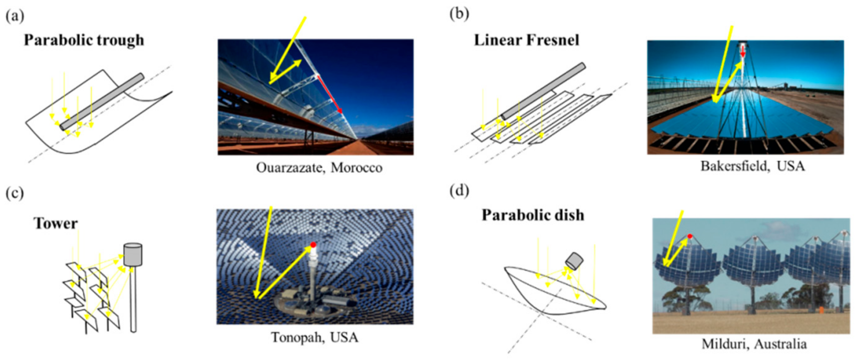
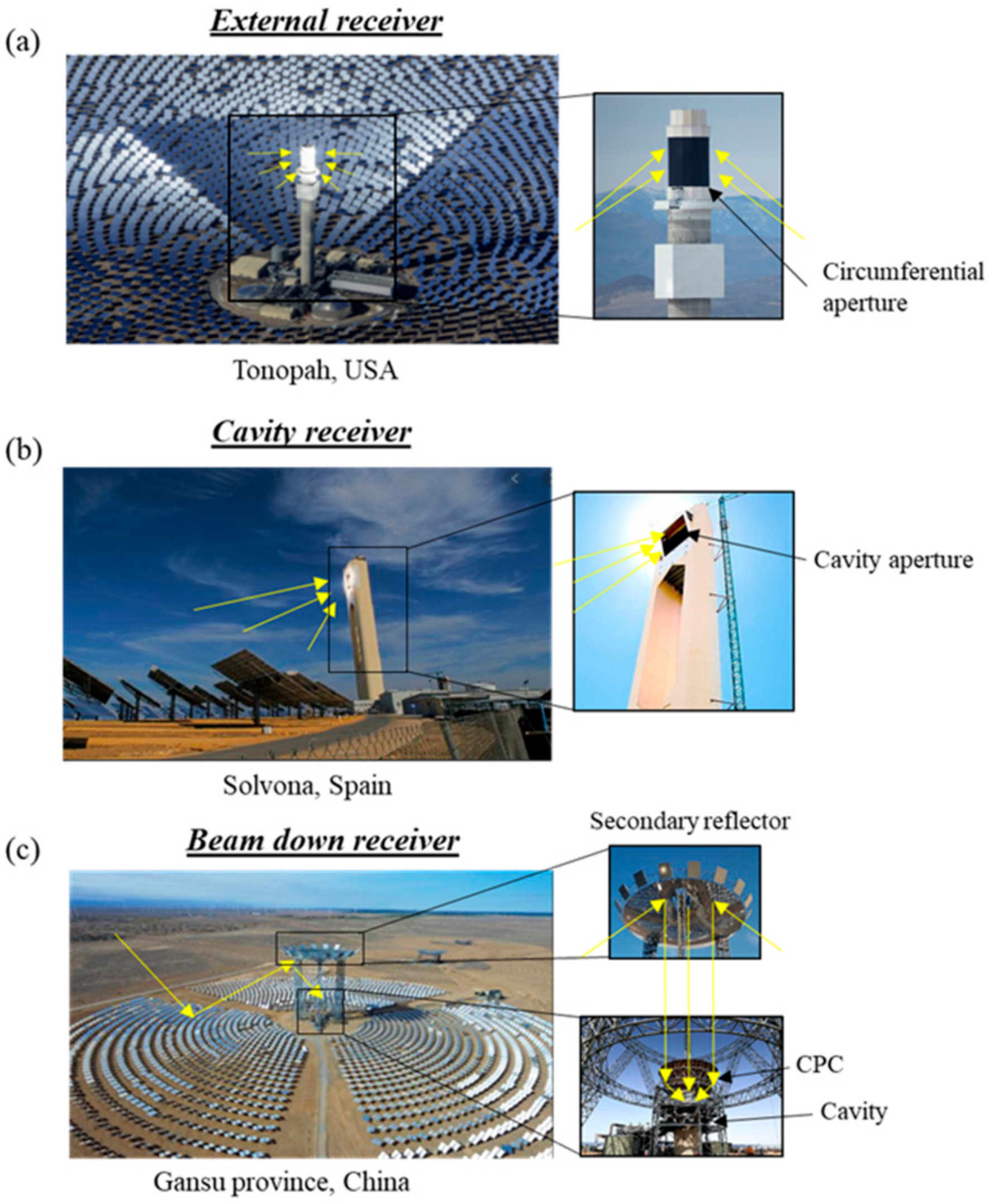
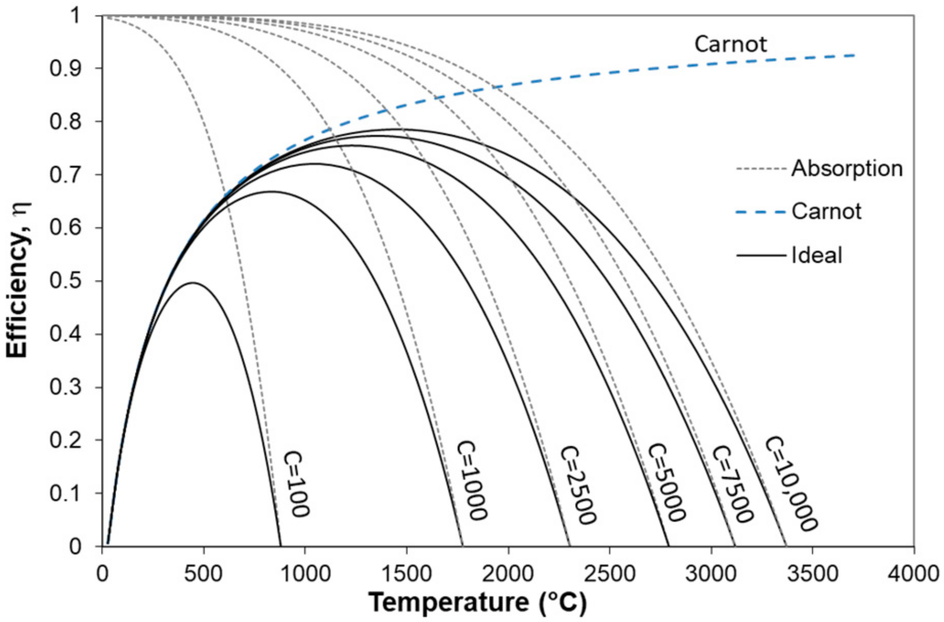
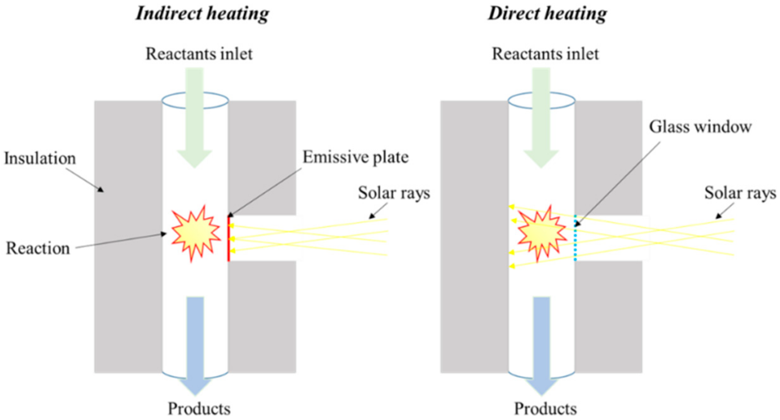
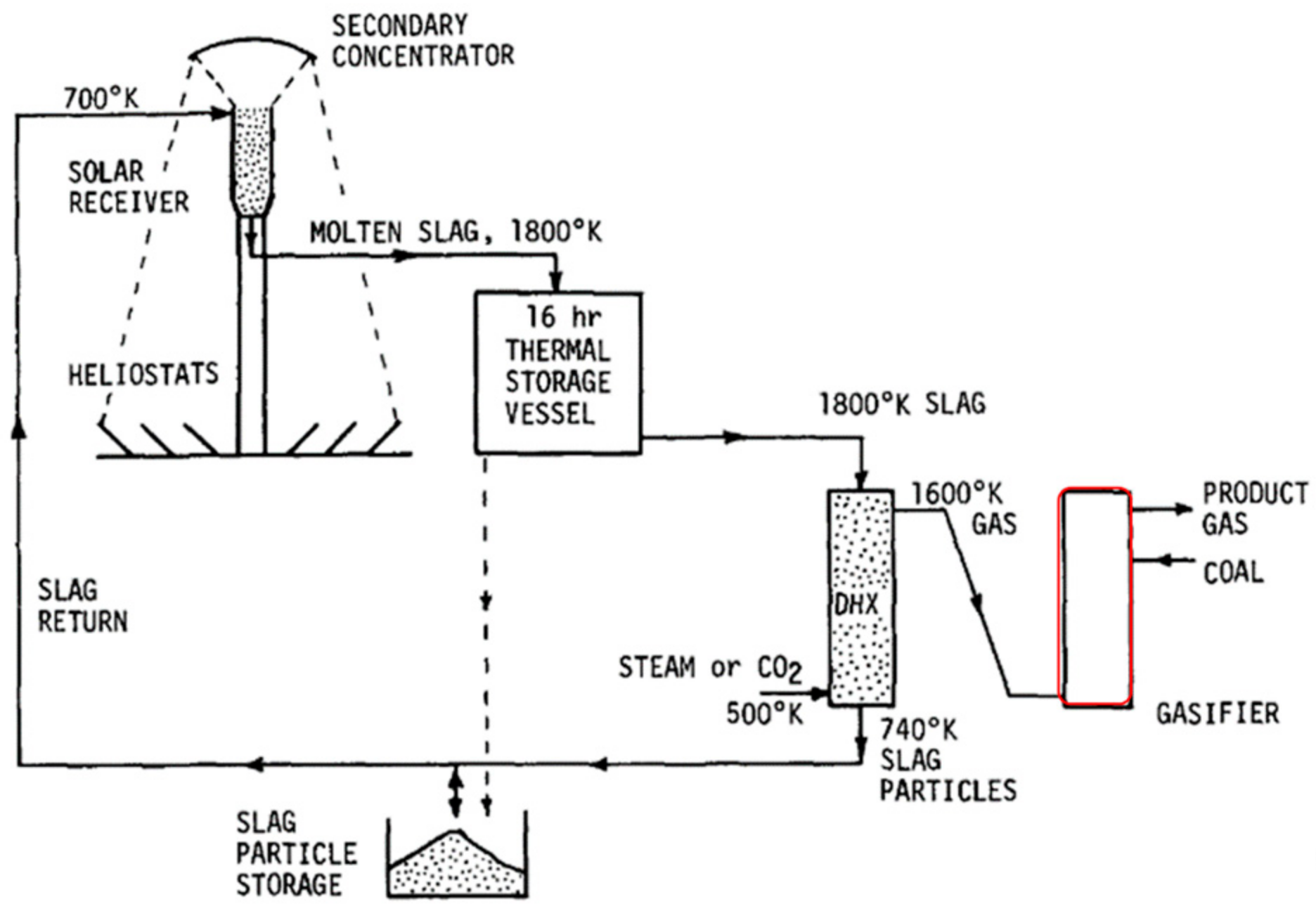
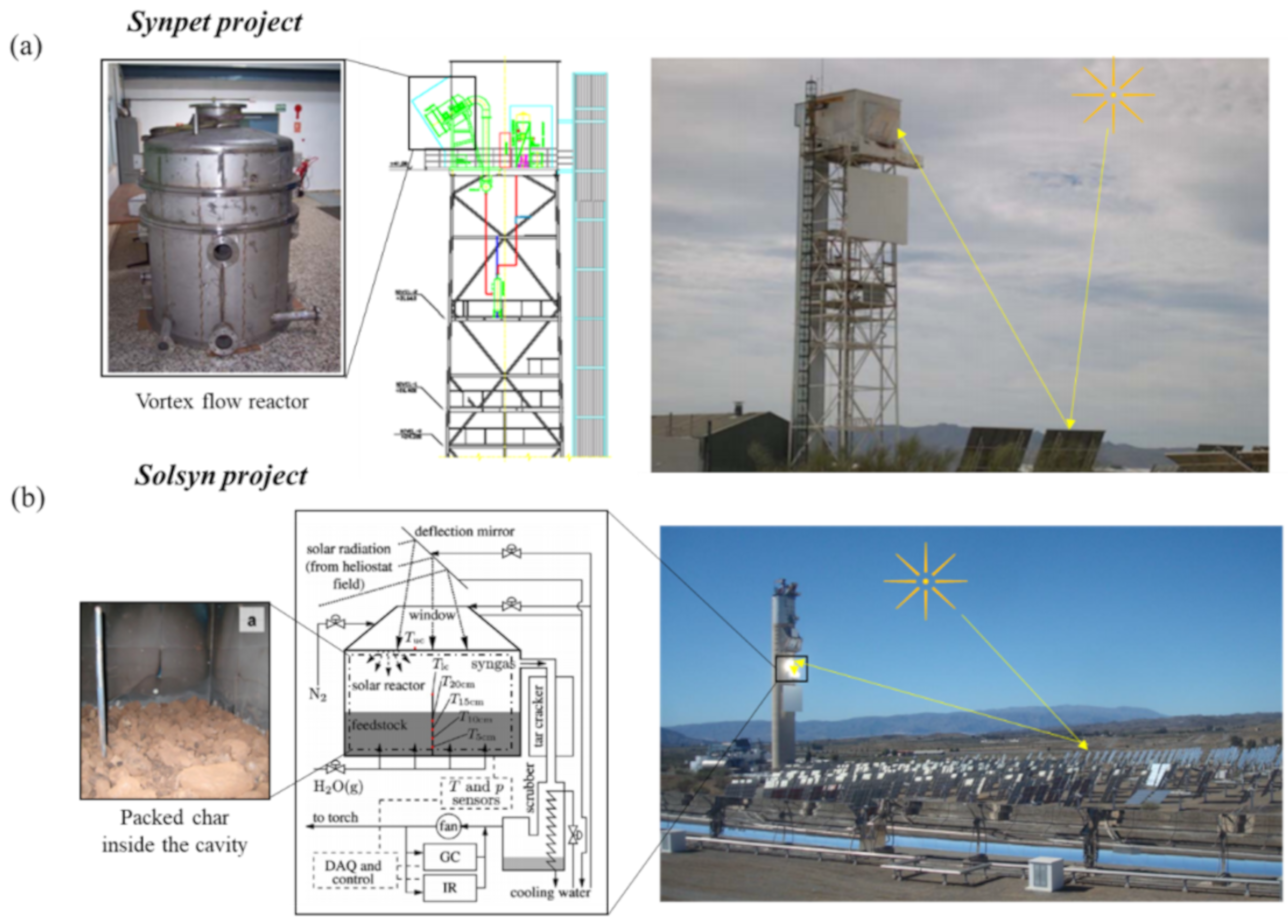
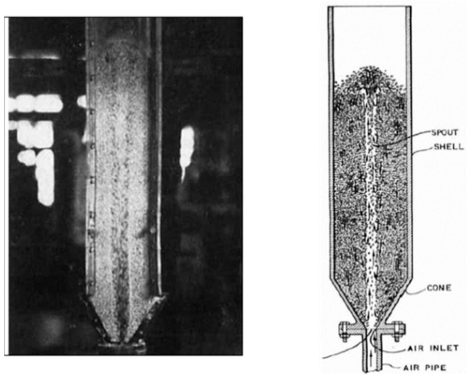
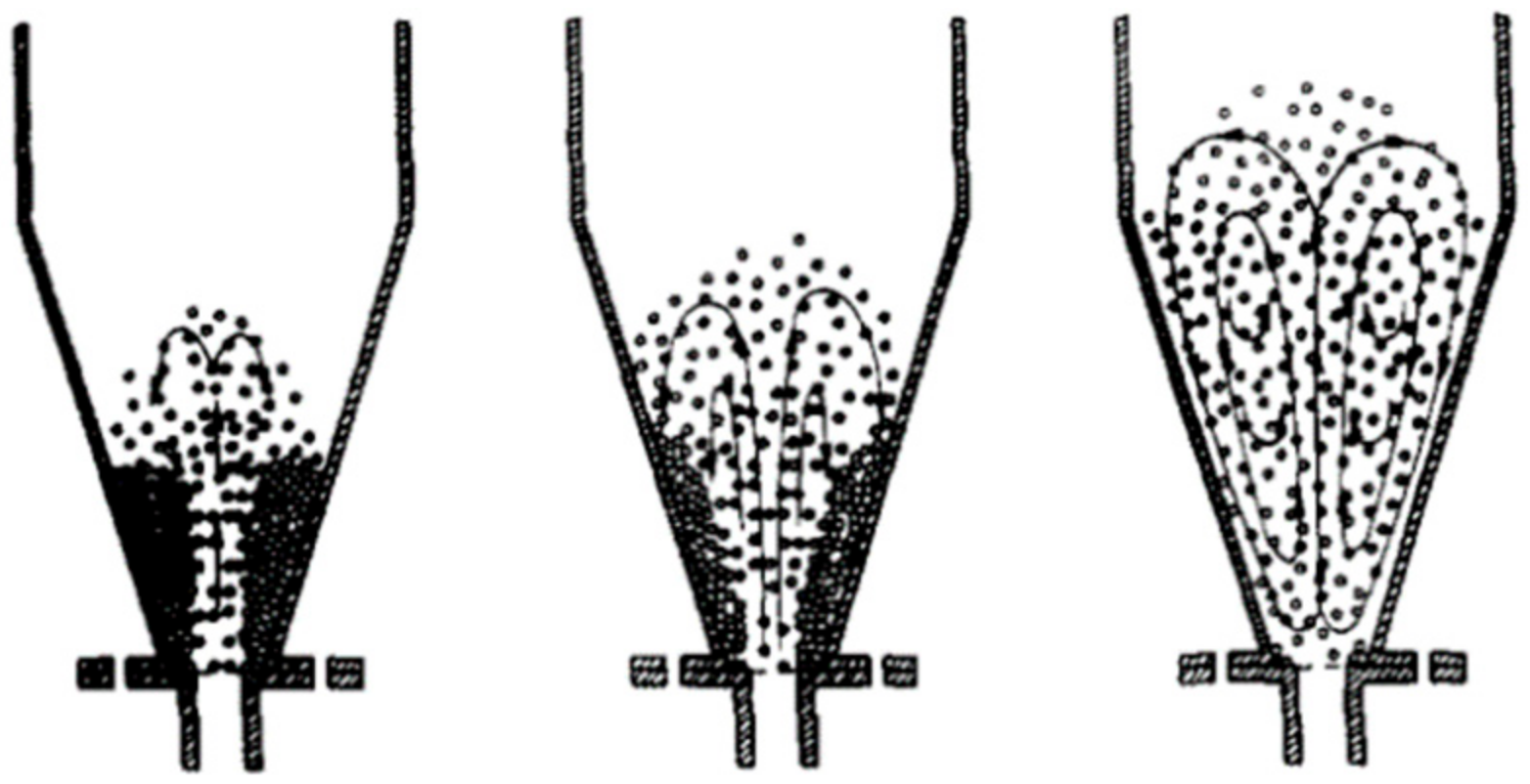
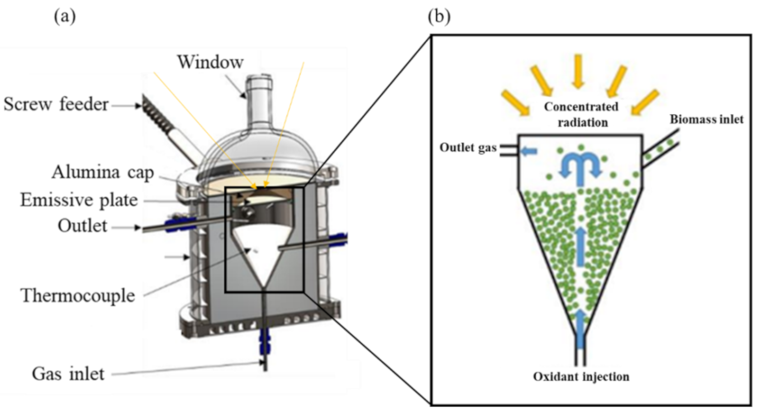
Table 1.
Summary of main previous solar reactor designs. Reproduced from [21], Elsevier: 2013.
Table 1.
Summary of main previous solar reactor designs. Reproduced from [21], Elsevier: 2013.
| (a) Gregg et al., 1980: Packed-bed reactor | (b) Taylor et al., 1983: Packed-bed (left), fluidized-bed (right) | (c) Piatkowski et al., 2009: Packed-bed reactor | |||
 |  |  |  | ||
| (d) Kodama et al., 2002, (left); Kodama et al., 2010 (middle); Gokon et al., 2012 (right): Fluidized-bed | (e) Z’Graggen et al., 2006: Directly irradiated vortex-flow reactor | (f) Müller et al., 2017: Indirectly irradiated vortex-flow reactor (windowless) | |||
 |  |  |  |  | |
Table 2.
Examples of novel approaches to deal with solar energy transients thanks to the use of an HTF or heat transfer solids (separated receiver and chemical reactor). Reproduced from [34,35], Elsevier: 2013.
| (a) Xiao et al., 2013: Molten salt | (b) Wu et al., 2020: Steam | (c) Guo et al., 2015: Bed particles |
 |  |  |
Table 3.
Cavity-type solar reactors dealing with solar energy transients. Reproduced from [37,41], Elsevier: 2017.
| (a) Hathaway et al., 2017: Molten salt reactor | (b) Muroyama et al., 2018: Hybrid solar/combustion fluidized bed reactor |
 |  |
Table 4.
Spouted bed variants. Reproduced from [58], Elsevier: 2017.
Table 4.
Spouted bed variants. Reproduced from [58], Elsevier: 2017.
| (a) Zhong et al., 2006: Spout-fluid bed | (b) Altzibar et al., 2014: Spouted bed with draft tube | (c) Lopez et al., 2017: Conical spouted bed with confiner and draft tube |
 |  |  |
Publisher’s Note: MDPI stays neutral with regard to jurisdictional claims in published maps and institutional affiliations. |
© 2021 by the authors. Licensee MDPI, Basel, Switzerland. This article is an open access article distributed under the terms and conditions of the Creative Commons Attribution (CC BY) license (http://creativecommons.org/licenses/by/4.0/).
Share and Cite
MDPI and ACS Style
Abanades, S.; Rodat, S.; Boujjat, H. Solar Thermochemical Green Fuels Production: A Review of Biomass Pyro-Gasification, Solar Reactor Concepts and Modelling Methods. Energies 2021, 14, 1494. https://doi.org/10.3390/en14051494
AMA Style
Abanades S, Rodat S, Boujjat H. Solar Thermochemical Green Fuels Production: A Review of Biomass Pyro-Gasification, Solar Reactor Concepts and Modelling Methods. Energies. 2021; 14(5):1494. https://doi.org/10.3390/en14051494
Chicago/Turabian StyleAbanades, Stéphane, Sylvain Rodat, and Houssame Boujjat. 2021. "Solar Thermochemical Green Fuels Production: A Review of Biomass Pyro-Gasification, Solar Reactor Concepts and Modelling Methods" Energies 14, no. 5: 1494. https://doi.org/10.3390/en14051494
Note that from the first issue of 2016, this journal uses article numbers instead of page numbers. See further details here.