
Resilience Assessment in Electricity Critical Infrastructure from the Point of View of Converged Security


1
Faculty of Applied Informatics, Tomas Bata University in Zlin, Nad Stranemi 4511, 760 05 Zlin, Czech Republic
2
Faculty of Safety Engineering, VSB–Technical University of Ostrava, Lumirova 13, 700 30 Ostrava, Czech Republic
*
Author to whom correspondence should be addressed.
Energies 2021, 14(6), 1624; https://doi.org/10.3390/en14061624
Submission received: 18 February 2021
/
Revised: 10 March 2021
/
Accepted: 12 March 2021
/
Published: 15 March 2021
(This article belongs to the Special Issue Critical Infrastructure Resilience Assessment and Management)
Abstract
:In terms of service provision, the electricity sector is the most important critical infrastructure sector, on the supply of which the vast majority of society and its basic vital functions depend. Extensive disruption of these supplies would have negative effects not only on basic human needs, but also on the economy and security of the state. For this reason, it is necessary to ensure permanent and comprehensive monitoring of the infrastructure elements resilience level, especially against threats with a multispectral impact on several areas of security. For this reason, the authors of the article developed the Converged Resilience Assessment (CRA) method, which enables advanced assessment of the electricity critical infrastructure elements resilience from the converged security point of view. Converged security in this case combines (converges) physical, cyber and operational security into a complementary unit. This reflects the integral determinants of resilience across related areas of security/safety. The CRA method focuses mainly on information and situation management, which integrates and correlates information (signals) from systems and sensors in order to obtain an overview of the situation and the subsequent effective management of its solution. The practical use of the proposed method is demonstrated on a selected element of the Czech Republic transmission system. The CRA method is currently embodied in a functional sample that has been piloted on several TSO elements. Further development of this method is seen mainly in fulfilling the logic of network infrastructure and reflection between elementary and intersectoral links in the context of synergistic and cascading effects in a broader context.
1. Introduction
Critical infrastructure is a comprehensive system, the essence of which is the permanent provision of services, necessary for the functioning of society [1]. The sectors that determine this system are classified into technical and socio-economic ones on the basis of functional specifics [2]. The most important technical sector of the critical infrastructure system, which is called uniquely critical on the basis of Presidential Policy Directive/PPD-21 [3], is energy. This unique criticality is especially evident in the electricity subsector, on the supply of which all other critical infrastructure sectors are depend [4]. The importance of the energy sector is also evident in critical infrastructure systems on other continents, such as Europe [5], Asia [6] or Australia [7].
The electricity sector is constantly exposed to the negative impact of security threats during the production, transmission and distribution of electricity [8,9,10]. For this reason, it is essential that its elements achieve a high level of resilience, which is defined in the critical infrastructure system as “the ability to reduce the magnitude and/or duration of disruptive events; the effectiveness of a resilient infrastructure or enterprise depends upon its ability to anticipate, absorb, adapt to, and/or rapidly recover from a potentially disruptive event” [11]. For this reason, it is necessary to constantly improve not only the tools for strengthening the resilience [12], but also the approaches to its assessment.
Current approaches to assessing resilience are based on the so-called single-issue approach. These include e.g., Assessing and Strengthening Organisational Resilience–ASOR Method [13], Critical Infrastructure Elements Resilience Assessment–CIERA Method [14], Availability-based engineering resilience metric and its corresponding evaluation methodology [15], Resilience Capacities Assessment for Critical Infrastructures Disruption: The READ Framework [16], A Quantitative Method for Assessing Resilience of Interdependent Infrastructures [17] and Guidelines for Critical Infrastructure Resilience Evaluation [18].
The disadvantage of the single-issue approach is that it allows only a separate resilience assessment in individual security areas, e.g., cyber security, physical security, process security, environmental security, organizational security. This does not consider the integral determinants of resilience across related areas. For this reason, the authors of the article created the method of Converged Resilience Assessment (CRA), which allows the electricity critical infrastructure resilience assessment from the perspective of converged security. Converged security in this case combines physical, cyber and operational security into one unit.
2. Current Approaches to Energy Critical Infrastructure Security Assessment
Within the analysis of the historical context, it can be concluded that the individual types of energy infrastructure elements security were considered as separate areas that solve only limited security problems. The most common was usually physical security [19], which extended to other infrastructure entities, possibly as needed, to other types of specific security important to them, such as personnel, administrative and others [20]. Later, with the development of database systems, information security began to be monitored and enforced, which was standardized by the group of international standards ISO/IEC 27000 [21] and relevant national certificates. With the development of packet communication, IP networks and the increasing incidence of various types of cyber-attacks, the importance of cyber security has begun to be emphasized [22]. In connection with packet network technologies such as the Internet, the concept of IT security began to appear, which referred to the association of cyber and information security into one functional unit [14,23]. At present, there is already a trend to address the security of the organization as a set of optimized solutions for all essential security types suitable for a given object and combine them into a single resulting security [24,25].
It can be stated, that recent approaches, mainly used to assess security in energy critical infrastructure, are focused on (1) risk assessment, (2) security system functions assessment, and (3) resilience indicators assessment. In the area of risk assessment, attention is paid to security assessment in the context of system vulnerabilities as a component of risk [26,27]. However, this approach does not create a logical assumption of the interconnection of individual security components, even with regard to a comprehensive assessment of the functionality and quality of the security system. Approaches focused on security system function assessment, presented e.g., in Garcia [28], Sridhar et al. [29] or Zhang et al. [30], assess the functionality of individual security aspects out of the interconnectedness and dependence of the integrated security system scope, which can be considered as grey spots of increasing security process, and thus the of critical infrastructure resilience. The third mentioned group of approaches focused on resilience indicators assessment, perceives security as an incomplete set of measures, logically unconnected components of security, divided into individual capacities or indicators of resilience [31] or from the perspective of a performance-oriented understanding of resilience [32].
It can be therefore stated, that it is recently possible to assess the energy critical infrastructure level security in in different ways. Risk assessment approaches emphasize the position of risk in the transferred meaning of critical infrastructure vulnerability, and to some extent reduce the importance and position of a comprehensive concept of individual security aspects interconnection and complementarity. In this context, in many cases only one aspect/component of security is used, which addresses only selected aspects of vulnerability for a specific limited and specific risk environment. Approaches assessing the selected group of security components functionality or functional parameters, delimit and to some extent isolate this group, without interconnection to other groups, or, conversely, there is a duplication and uncertainty level increasing in the functionality assessment process. Therefore, it can be argued that the link between cyber security and the detection function of the physical protection system is often not obvious. Approaches assessing capacity, performance or resilience indicators as an extension of critical infrastructure protection approaches in many cases include the same or similar aspects or components of security in individual resilience attributes, which is creating duplication and ambiguity of complementarity and interconnectedness.
Due to the presented shortcomings of the mentioned approaches, the authors intended to develop an approach enabling factual, logical and functional interconnection, i.e., convergence of the most important aspects and components of security, considering the critical infrastructure energy sector specifics. The following text therefore presents the framework and the methodology of converged security assessment combining physical, cyber and operational security, in the context of the electricity critical infrastructure resilience assessment process.
3. Converged Security: Principles and Solutions
Security is one of the basic attributes of modern society. The aim of security as a field is to protect reference objects (e.g., people, organizations, critical infrastructure) and especially their assets from damage, or to minimize the impacts caused by security breaches. The reference object actively ensures its security through security types [33]. The security type is a set of measures designed to ensure security in a defined part of the security environment [34]. It is a systematic and repeated solution of undesirable phenomena of certain security type breaches. In particular, due to technological development, the number of security types that the reference object must provide as part of its protection is increasing. For a manufacturing plant reference object, these security types include physical security, cyber security, administrative security, and occupational health and safety. If required or it is necessary, operational security, personnel security, environmental safety, radiation safety, safety of technical equipment, etc. can be added to them [35].
At present, the various individual security types operate independently of other security types. This way of ensuring security has a number of negatives. One of the basic disadvantages of this situation is the inability to link the unmasking symptoms of the emerging security breach, detected by sensors in individual security types of, into one unit. For example, if a company employee wants to illegally copy data from the server directly in the server room, there is currently no cyber security option to detect it by connecting data from the server room access system with data on copying data directly from the server’s USB port. Another negative of the above-mentioned conditions is the increasing costs of ensuring security, resulting from the independent provision of security individual types. This is reflected both in the technological side and especially in the personnel or organisational side. Each security type is usually provided by a separate group of experts, has its own security technologies and protection processes, its own financial budget [36].
At present, for practical reasons, it is necessary to look for ways to combine individual security types into one unit. This trend has resulted in the concept of converged security, which is a specific type of security created by merging multiple compatible types of security into one whole [37]. This security type makes it possible, thanks to the analysis of the correlation of the earlier (even at the stage of symptoms) security breaches manifestations, to detect emerging security breaches faster and better and to ensure their solution in a more targeted manner. Converged security usually includes physical security and cyber security [38]. However, the structure of the merged security types may be different. The trend of converged security is a formal cooperation between previously different security functions. In the context of the new technological concepts development, such as IoT, Industry 4.0, Smart Cities, there is a huge increase in data flow, which can be assessed only on the basis of the bulk data processing algorithms.
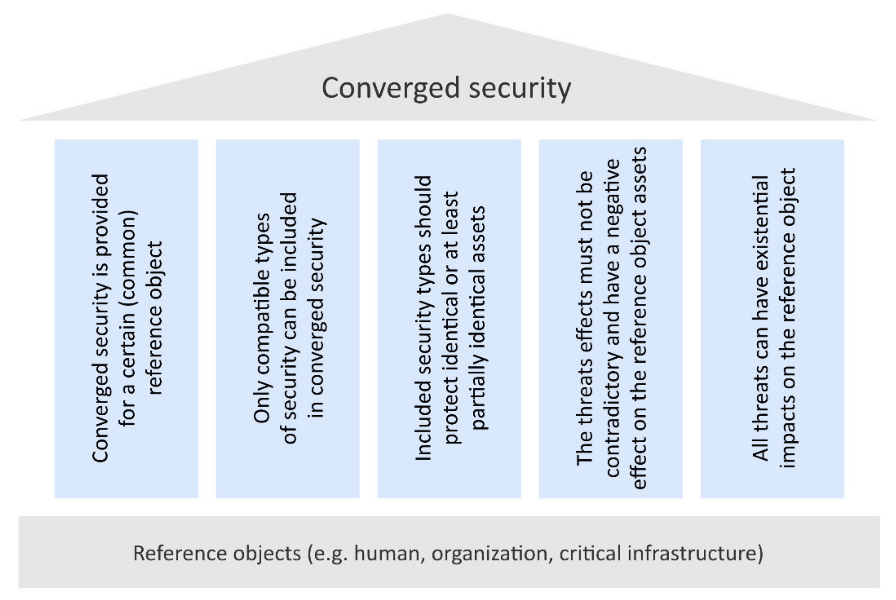
This compatibility is based primarily on the need to protect the reference object same assets. Another condition for compatibility is the temporal characteristics of the security breach manifestations, which should be approximately the same. In the above example of converged security, the manifestations will be in the seconds–minutes–hours’ time range. If the security types were merged, with one changing in minutes and the other in years, then merging into converged security would be meaningless, because the dominant role would be played by the security type with short time changes time. The basic principles on which converged security is based are presented in Figure 1.
It follows from the abovementioned principles that converged security is ensured at a common reference object. This reference object has one or more assets and all the security types are involved to contribute to ensuring their security. Converged security combines these security types into one unit [39]. This makes it possible to assess the state of the security situation as a single image, in which all partial security situations of individual security types are projected. The added value of merging previously independent security types is the possibility of perceiving the correlation of individual security breaches manifestations into one unit, faster detection of security breaches, its manner, extent and prediction of a scenario possible future course. Other significant benefits of converged security include a comprehensive and up-to-date security situation assessment. This assessment makes it possible to adequately address the security situation and thus minimize the negative effects of security breaches. From the reference object point of view, the state of the security situation is most often assessed using the resilience level of its protection system (security system), or the resilience of the reference object as such. For converged security, the resilience of the protection system is assessed [40]. The fulfilment status of the reference object target function is not assessed, but the reference object assets protection state through reference object the protection system. The protection system consists of measures taken in individual security types.
4. Basis for Resilience Assessing from the Converged Security Perspective
Resilience is one of the basic parameters that are monitored within individual security types [24]. In this context, resilience is perceived as a property of the reference object protection system, which expresses how the given unit is prepared to protect and defend the reference object and its assets, or to manage the harmful effect of individual threats [41]. Ongoing and up-to-date knowledge of the protection system resilience level enables individual security breaches to be addressed and effective remedial action to be taken. If the individual protection system parameters deteriorate due to deficiencies in the organization and security, due to technical failures or due to climatic conditions, its resilience also decreases [42]. Failure to address the decline in resilience level may, in the event of a security breach, lead to an easier overcoming of the protection system and damage to reference object assets. Real-time resilience assessments should identify such situations and allow adequate measures to be taken to protect assets, restore resilience and remedy the situation [43].
The reference object protection system resilience from the converged security point of view represents the ability of measures (implemented in individual security types included in converged security) to protect its assets and thus ensure the fulfilment of the reference object target function. The resilience assessment should reflect its current level as a reference object attribute. This attribute can be monitored by sensing manifestations or changes in external and internal factors [44].
In general, any change in resilience can be qualitatively or quantitatively reflected, and therefore the effects and impacts on the reference object resilience can be assessed. Thus, the resilience assessment can be based primarily on sensing those changes in the state of factors that are substantially reflected in the resilience changes [45]. In this case, the degree of these factors influence on the element resilience can be expressed in the form of a penalty. The penalty assesses how much the level of protection system resilience has decreased during the change of condition. In relation to certain assets, all key factors that describe changes in the protection system resilience are referred as penalty factors.
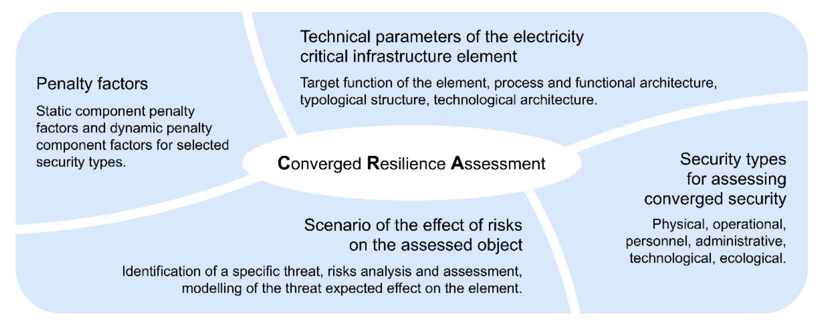
Based on the above, it can be confirmed that the specific level of protection system resilience is a function of all significant changes and manifestations, the consequences of which apply at the time and have a significant impact on the reference object in terms of damage to its assets. In this context, the authors of the article defined the framework for converged resilience assessment (see Figure 2), which is the starting point for resilience assessment from the converged security perspective.
The essence of the Converged Resilience Assessment (CRA) framework is to define the four areas necessary to ensure support for the assessment process. These areas provide not only the information needed for the assessment (i.e., the technical parameters of the electricity critical infrastructure element and the penalty factors), but also the information defining the environment in which the assessment will take place. The definition of this environment is realized by selecting specific security types for the converged resilience assessment and defining a specific risks effects scenario on the assessed element. Based on this information, it is possible to start the assessment process, the course of which is described in the following part of the article.
5. Converged Resilience Assessment in Electricity Critical Infrastructure
Based on current requirements and the need to reflect on the current security challenges of the electricity critical infrastructure sector, also due to its importance, the authors developed the Converged Resilience Assessment (CRA) method, which allows resilience assessment in critical infrastructure from a converged security perspective. Converged security in this case combines (converges) physical, cyber and operational security into one unit. It focuses mainly on information and situation management, which integrates and correlates information from systems and sensors in order to obtain an overview of the situation and the subsequent effective management of its solution. The resilience assessment can be performed for electricity critical infrastructure element individual assets as a whole. In case when is necessary to divide the element object into parts, it is possible to assess the resilience by individual parts and to obtain the resulting element resilience level by aggregating individual partial resiliencies.
5.1. Reference Object Resilience Assessment
The essence of the CRA method is to determine the electricity critical infrastructure elements protection system resilience from the converged security point of view, using the resilience index of reference object . This index expresses the extent to which the reference object assets are protected against related risks, potentially minimized by specific security types included in converged security. The resilience index in this case is a dimensionless number, the value of which ranges from 0 to 100. The value 100 expresses the maximum resilience, the value 0 the minimum resilience.
As converged security contains more than one security type and the reference object usually includes more than one asset, the resilience indices of the individual assets must first be determined for each security type. From these values, the reference object resulting resilience index for a given security type, i.e., physical, cybernetic and operational, is then determined by aggregation. This resulting reference object resilience index is calculated by the arithmetic mean of the individual security types resilience indices. The relationship between the above variables is presented in Equation (1):
where = resilience index of the reference object; = resilience index of the i-th security type; = number of converged security types; = physical security resilience index of the j-th asset; = cyber security resilience index of the j-th asset; = operational security resilience index of the j-th asset; = number of assets assessed.
Aggregation through assets is also possible. This means that the resulting resilience indices for a given security type by aggregation determine the resulting resilience index for that asset. The total converged resilience index of the reference object is then obtained by aggregating the resilience indices of all the assets that are part of the reference object. However, for this aggregation it is necessary to use the weighted arithmetic mean of the converged resilience of individual assets. The mathematical notation of this method of calculation is presented in Equation (2):
where = resilience index of the reference object; = converged resilience index of the j-th asset; = j-th normalized weight of the j-th asset; = number of assets assessed.
The resilience of the reference object is determined as an abstract value, the magnitude of which ranges from 100 to 0 points. The default resilience value is set to 100. This resilience value is achieved by a protection system that has all the required measures implemented and at the same time no penalty has been activated. In practice, such a state is difficult to achieve. The assessment itself is determined by decrementing this final value (100) according to the detected problems/incidents. The value 100 can therefore be imagined as a state of “required (absolute) resilience of the object”. And the problems just detected are understood as penalty factors that reduce this value. The lower resilience limit of the reference object is limited to 0. Achieving zero resilience represents a state where no protection system measure is working or a state where all penalty factors are activated. In practice, however, even if the protection system is overcome, such a situation usually does not occur. It follows that the resilience of the protection system usually does not decrease to 0.
5.2. Calculation of Converged Asset Resilience
Converged resilience index of the asset j is the aggregation of asset resilience indices for individual security types, i.e., , , . The value of the index also ranges from 0 to 100. The calculation of the resilience index is performed using penalty factors so that the reduction in resilience caused by penalty factors is subtracted from the default value of 100. Penalty factors are divided into static and dynamic. These factors depend on the two parts of the protection system, the static part and the dynamic part. The static part reflects the penalty obtained for the measures that the protection system should have and does not have at the given time. This is usually based on a standard that defines the structure and measures of the protection system in a given security type. Alternatively, an overview of recommended measures in the form of “best practices” can be used (the definition of penalty factors is given in Section 5.3). Key measures include security policy, physical security, mechanical barrier systems, alarm systems, anti-virus protection, etc. The dynamic part of the equation then reflects the penalty obtained by the intruder, failures, non-compliance with regime measures and dynamically corrects the value of static penalties.
Calculation of the converged resilience index of the asset according to the Equation (3) is based on arithmetic aggregation of asset resilience indices for individual security types:
where = index of asset converged resilience; = asset physical security resilience index; = asset cyber security resilience index; = asset operational security resilience index.
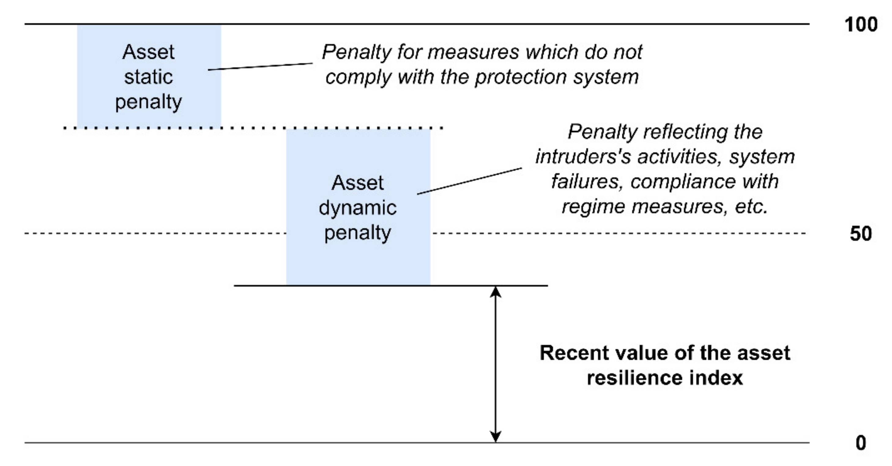
The essence of the calculation of the asset resilience index for individual security types , , is presented in Figure 3.
Based on Figure 3, it is possible to determine Equation (4) for calculating the asset resilience index for individual security types:
where = asset resilience index of a given security type (i.e., physical, cyber or operational); = asset static penalty index; = asset dynamic penalty index.
The calculation of the asset static penalty index is performed according to Equation (5):
where = asset static penalty index; = active static penalty factor in a given security type; = static penalty factor in a given security type.
The calculation of the asset dynamic penalty index is performed according to Equation (6):
where = asset dynamic penalty index; = active dynamic penalty factor in a given security type; = dynamic penalty factor in a given security type.
The following text presents an example of calculating the asset static penalty index of the type of physical security (see Table 1). At this stage of the resilience assessment, a convergent approach is already evident, the essence of which is to consider the effects of the physical security penalty (see column PS) in all three security types. A similar approach would also assess the area of cyber security (in the CS column) and the area of operational security (in the OS column).
The bold marked active physical security static penalty factors express in a figurative sense the non-fulfilment of the formulated factors found during the selected asset security assessment, which leads to their activation. In the case of dynamic penalty factors, the procedure is analogous.
5.3. Defining Penalty Factors
Penalty data (penalty) is a number generated statically or dynamically on the basis of a certain finding or change of the observed factor (agent), having or reflecting a significant effect on resilience. The amount of the penalty is directly proportional to the degree of change effect or finding on resilience.
As part of the resilience assessment process, detected problems (e.g., absence of security documentation, failures of alarm devices, intrusion detection, etc.) are considered as penalty factors that reduce this value. Penalty factors can be classified into static and dynamic.
Static factors are those effects that affect the protection system until they are eliminated, but it is a long-term effect. They do not repair/appear themselves. In this section, there are problems/incidents, which are mostly based on the absence of processes necessary to manage security, the absence of physical security elements, non-compliance with applicable legislation, missed inspections, revisions, etc.
Dynamic factors are factors that change over time as a result of changes in the security situation, and their duration is not accurately predictable. These include, for example, motion detection using a camera system, security breaches reported by intrusion detectors, failures of security systems or power outages. For these factors, it is necessary to determine the observed time action of the factor. During the period of action, the factor is identified as an incident and contributes to the reduction of the object’s resilience. After the time has elapsed, the factor is archived and the resilience of the object increases again.
Various threat lists and descriptions of protection systems are a suitable source for processing the list of penalty factors. Project documentation of alarm systems, computer networks and systems for their protection, etc. may be used to create such lists. The results of security assessments and security audits may also be used. In addition to knowledge and practical experience, the following materials in particular can be used as basic starting points for the creation of general catalogues:
- structures and requirements for intruder and hold up alarm and emergency systems, e.g., according to a number of technical standards EN 50,131 [46];
- structures and requirements for video surveillance systems, e.g., according to a number of technical standards IEC 62,676 [47];
- structures and requirements for electronic access control systems, e.g., according to a number of technical standards IEC 60,839 [48];
- structures and requirements for emergency call systems, e.g., according to a number of technical standards EN 50,134 [49];
- structures and requirements for alarm transmission systems and equipment, e.g., according to a number of technical standards EN 50,136 [50];
- results of security audits;
- common requirements for alarm systems, e.g., according to a number of technical standards EN 50,130 [54];
- standard equipment of buildings with technical equipment of buildings–heating, air conditioning, ventilation, electricity, water, etc.;
- facility management documentation;
- standard operating procedures;
- threat catalogues;
- security standards;
- organization of physical security;
- legal security requirements (fire safety, cyber security, chemical accidents, protection of classified information, construction requirements, etc.);
- requirements of insurance companies and others.
The calculation of the static penalty factor value is realized according to Equation (7):
where = static penalty factor in a given security type; = active static penalty factor value; = significance coefficient. The calculation of dynamic penalty factors is realized analogously.
Penalty of static penalty factor ranges in the interval , where the static penalty factor maximum penalty point value is in the interval and the significance coefficient is evaluated in the interval . A wider range of multicriteria methods can be used to determine the relevant point values of the penalty and the significance coefficient [55]:
- Checklist in combination with the point method,
- Multicriteria evaluation of the size of the penalty,
- Method based on expert estimation,
- Fuller’s method,
- Modified Saaty method,
- Pairwise comparison extended by ELO rating,
- Metfessel allocation.
5.4. Procedure for Reference Object Resilience Assessment
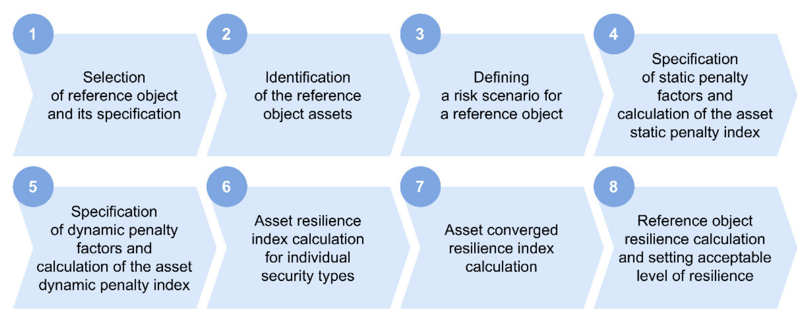
Based on the above relationships, it is possible to proceed to the definition of the procedure for reference object resilience assessment in electricity critical infrastructure (see Figure 4).
The first step in the resilience assessment procedure is the selection of the reference object and its specification (step 1). This specification focuses on the technical parameters of the element, which are mainly the element target function, process and functional architecture, typological structure and technological architecture.
The next step is to identify the reference object assets (step 2). In terms of the overall clarity of the results, it is appropriate to select only the minimum set of the most important assets that fundamentally affect the reference object security behaviour, because the reference object resilience will always be performed separately for each asset.
Following the identification of assets, it is necessary to define a risk scenario for the reference object (step 3). These include defining a specific threat, analysing and assessing risks and modelling the expected threat impact on an element.
The specification of static assets penalty factors and the calculation of the static penalty index (step 4) and the specification of dynamic assets penalty factors and the calculation of the dynamic penalty index (step 5) are implemented in a similar way. The calculation of penalty factor values is performed according to Equation (7). The calculation of static asset penalty indices is performed according to Equation (5) and the calculation of dynamic asset penalty indices is performed according to Equation (6).
The next step is the calculation of asset resilience indices for individual security types (step 6). This calculation is performed separately for each asset in the area of physical, cyber and operational security, according to Equation (4). Subsequently, the converged asset resilience index is calculated for each asset (step 7), according to Equation (3).
The first part of the last step (step 8) is the calculation of the reference object resilience, which is performed by the weighted arithmetic average of the individual assets converged resilience according to Equation (2). In the case of reference object resilience index calculation according to Equation (1), the calculation is performed using asset resilience indices for individual security types. In this case, step 7 can be omitted. The second part of this step is to set an acceptable level of resilience. The determination of this threshold may be based, for example, on approaches to assessing the reliability (or functionality) of physical protection systems [28,56].
6. Case Study of Practical Application of CRA Method
The last part of the article is intended to demonstrate the practical application of the CRA method in the form of a case study on a selected electricity critical infrastructure element. For this purpose, a real transmission system element of the Czech Republic was selected, which is referred to as a reference object. Due to the need for protection, the identification data of the selected electricity critical infrastructure element are anonymized. The resilience assessment of this element was carried out in cooperation with the security liaison officer of the relevant entity (operator) of the critical infrastructure. Three types of security, physical, cyber and operational, were selected to converged resilience assessment.
6.1. Selection of Reference Object and its Specification
Based on long-term experience in the field of transmission system network protection, a very high voltage substation 400 kV or 220 kV/110 kV was chosen as the reference object, which belongs to a selected anonymised electricity transmission system operator (TSO).
A typical substation in a transmission system usually consists of two separate buildings. In the TSO building, voltage levels of very high voltage (220 kV) and especially high voltage (400 kV) are distributed to neighbouring TSO buildings. Subsequently, it is transformed to a high voltage level (110 kV), which is then distributed to the neighbouring electricity distribution substation (DSO). Both TSO and DSO facilities cooperate with each other, but they have separate entrances and perimeter protection. The selected reference object will represent only the very high voltage part of this substation, which is the TSO property.
6.2. Identification of the Reference Object Assets
From the point of view of the overall clarity of the results, it is appropriate to select only the minimum set of the most important assets that fundamentally affect the security behaviour of the assessed reference object, because security risk assessment and reference object resilience assessment will always be performed separately for each asset. The resulting resilience of the entire reference object is obtained by aggregating the resilience indices relative to the individual assets. The assets listed in Table 2 were identified for the selected very high voltage substation reference object.
For easier clarity, the author’s team set a limitation where the reference object will be expressed only by asset A1. The calculation of the converged security index of assets A2, A3 and A4 would proceed analogously and Equation (1) would be used in the conclusion. In this context, it is necessary to state that the principle and rule of N-1 is widely applied in the Czech Republic [57]. However, in the case of the transmission system of the Czech Republic, it is primarily a line infrastructure, not a point infrastructure, as is the case with the selected critical infrastructure element. We therefore admit that in the context of redundancy, the availability of a replacement transformer can be assumed, but within the Czech Republic these are primarily transformers of 220 kV and lower.
6.3. Defining a risk Scenario for a Reference Object
In the context of the following scenario, the effect of risks is perceived as the application of a dynamic penalty in the individual stages of the scenario. Due to the application aspect of the presented methodology, four types of signals were defined, which will occur in a certain sequence and will subsequently be minimized by the measures taken:
- -
- Signal STF1–Alarm state Intruder and hold up alarm system–Violation of the interior of the building;
- -
- Signal STF10–EFS–Fire alarm;
- -
- Signal STP19–Power failure III–Partial power failure in the building;
- -
- Signal SPK12–Key infrastructure power failure–shutdown.
The set of these signals and their meaning can be modified or supplemented at any time as needed during the testing of a functional sample for a reference object. Each STx and SPx signal has two variants, namely “on” and “off”. By a suitable choice of combinations of signals STx (on, off) and SPx (on, off), the characteristic courses of changes in the reference object resilience, which could occur in practice, will be simulated for the purposes of the functional sample.
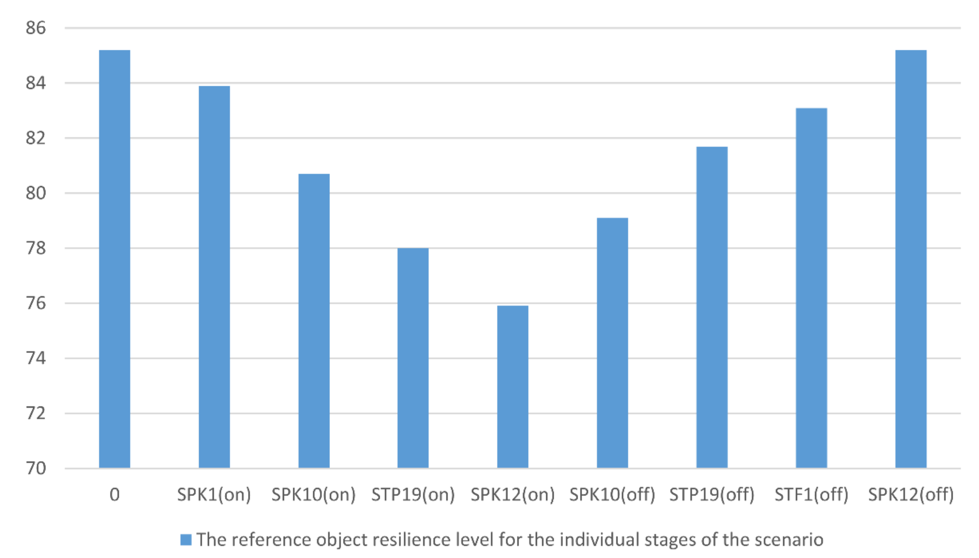
As an illustrative example, a scenario was defined including the following stages of incidents: Default state–STF1 (on)–delay–SPK10 (on)–delay–STP19 (on)–delay–SPK12 (on)–security situation resolution–delay–SPK10 (off)–delay STP19 (off)–delay–STF1 (off)–delay–SPK12 (off)–default state.
The individual stages of the scenario characterize the reference building surrounding disturbance incident, when the key information infrastructure is switched off with an unauthorized triggering of a fire alarm and a purposeful partial power failure in the building. After these events, security and technicians come to the building to investigate the incident and gradually minimalize its consequences, bringing the resilience of the reference building to its original initial state. The calculation of individual asset resilience indices presented in the following chapters.
6.4. Specification of Static Penalty Factors and Calculation of the Asset Static Penalty Index
The next step in reference object resilience assessment is the specification of static penalty factors and the calculation of the asset static penalty index. Table 3 specifies the penalties that can be applied to asset A1 (transformer) in the reference object. If “no” is given in the table, then the measures are sufficient and minimize the risks arising from the characteristics of the factor. In this case, it is not necessary to apply this penalty factor to the protected asset. If “yes” is listed in the table, the penalty factor is applied. Equation (5) is then used to calculate the asset static penalty index.
6.5. Specification of Dynamic Penalty Factors and Calculation of the Asset Dynamic Penalty Index
Similar to static factors, the specification of dynamic penalty factors and the calculation of the asset dynamic penalty index are performed in this step. Table 4 specifies the dynamic penalty factors and the calculation of the dynamic penalty index in the context of the specified course of the selected dynamic factors scenario activation. At the end of the table, the value of the selected asset dynamic penalty index for individual scenarios is calculated using equation (6).
The calculation of the asset dynamic penalty index is performed gradually according to the scenario defined in Section 6.3. First, the penalty factor “Intruder and hold up alarm system alarm state–Violation of the internal space of the object” is applied, on the basis of which the index was calculated. In the next phase of the scenario, the value of the penalty factor “Electric fire signalization–Alarm” is added to the first penalty factor and the index was calculated. Subsequent activation and then gradual deactivation of other penalty factors according to the scenario additional indices of asset dynamic penalty was calculated.
6.6. Asset Resilience Index Calculation for Individual Security Types
Based on the calculation of the static penalty index, which is constant over time, and the calculation of the dynamic penalty index, which is variable in the context of the determined scenario of selected dynamic factors activation, the asset resilience index for individual security types was calculated according to Equation (4). The resulting asset resilience indices for the individual stages of the dynamic factor activation scenario are presented in Table 5.
6.7. Asset Converged Resilience Index Calculation
As already stated, selected asset resilience index calculation according to equation (3) it is based on arithmetic aggregation of asset resilience indices for individual security types. The resilience value of the selected asset changes over time, due to the defined stages of the scenario of selected dynamic factors activation. The value of the asset converged resilience index is presented in Table 6.
6.8. Reference Object Resilience Calculation and Setting Acceptable Level of Resilience
Reference object resilience calculation it is based on the fact that converged security contains several types of security and the reference object usually includes more assets. In the previous sections of Articles 6.3 to 6.7, the procedure for asset A1 converged security index calculation according to Equation (3) was presented. The procedure would be analogous to the assets A2, A3 and A4 converged security index calculation, and then Equation (2) would be applied to calculate the reference object converged resilience. In this context, a restriction has been set for better clarity, where the reference object is expressed by only one asset A1 and thus the weighting coefficient for this the asset is equal to 1. The resulting reference object resilience value is presented in Table 7.
Figure 5 presents the progression of the asset A1 resilience within the individual stages of selected dynamic factors application. Default reference object resilience index value it is based on the value of the initial resilience (i.e., 100%) after deducting the static penalty factors average value presented in Table 3. This initial level is further reduced in the context of the individual stages of the dynamic penalty factors application scenario. After minimalization of the causes formulated in the scenario, the asset converged resilience value gradually returns to its default value.
At the end of the case study, it is necessary to set an acceptable level of resilience, which detects the moment when, for example, the physical protection system is no longer able to withstand the effects of threats. Determining this threshold for the application of the security personnel reactive function is a very complex and ambiguous process, even with regard to the spectrum of analysed literature and research activities. In the context of the case study presented above, the resilience acceptable level was set at 70%. This value was to some extent inspired by approaches to assessing the reliability (or functionality) of physical protection systems, where, for example, Garcia [28,56] states that technical reliability in the figurative sense of the reliable system function standard deviation is approximately 30%. This statement is in a sense substantiated by other professional publications, e.g., Oyeyinka et al. [58].
Based on these facts, the author’s team accepted this fact as a starting point for determining the value of the functionality required value and fulfilling the requirements of converged security individual aspects, in a figurative sense to the value of resilience acceptable level. The author’s team is aware that setting the limit of resilience acceptable level may also have an aspect of subjectivity and expertise, but it leans towards the opinion arising from the mentioned publications. Based on this, it is possible to declare that the resilience changing value of the asset A1 within the selected dynamic factors application individual stages did not exceed the limit of the resilience acceptable level. This fact is to some extent confirmed by the system return to initial state without a significant impact on the electricity critical infrastructure element functionality.
7. Conclusions
The aim of the article was to describe the CRA method, which allows the electricity critical infrastructure elements converged resilience assessment. The essence of this method lies in expressing the influence of individual events and their dynamics on the overall element’s resilience. The effect of events, referred to as penalty factors, is expressed in terms of the penalty value. The more intensive events effect on the resilience reduction, the higher penalty value. The penalty factors themselves are divided into static and dynamic. Static factors are unchanged depending on the progression of the situation and to change them it is necessary to take an active action, such as taking relevant measures. On the contrary, dynamic factors change according to the progression of the situation or event. Resilience is first assessed for individual security types, i.e., physical, cyber and operational, and then they are aggregated into the reference object resilience index resulting value.
The benefit of the CRA method is the reflection of the all events influence on the protection system converged resilience. The method focuses mainly on information and situation management, which integrates and correlates information from systems and sensors in order to obtain an overview of the situation and the subsequent effective management of its solution. The application benefit of the method is the element resilience predictive assessment, which provides the organization’s management with information on the elements ability to withstand the threats effects with a multispectral impact on multiple security types and areas.
The practical application of this method, which was demonstrated in the form of a transmission system selected element case study, demonstrated the functionality and applicability of the proposed procedure and the ability to reflect the local specifics of the electricity infrastructure selected element with its specific and unique security and protection aspects. In conclusion, it can be stated that the method is currently embodied in a functional sample, which was piloted on TSO several elements. The further development of this method is seen mainly in the fulfilment of the network infrastructure typology logic and the reflection cross-elemental and cross-sectoral links in the context of synergistic and cascading effects in a broader context. In this context, it is also worth noting that the CRA method may, after adequate modification of penalty factors, be applicable not only in the field of electricity, but also for the assessment of element resilience in related subsectors, such as gas or water infrastructures.
Author Contributions
Conceptualization, M.H. and D.R.; Methodology, M.H. and L.L.; Validation, M.H. and L.L.; Formal Analysis, M.H. and D.R.; Resources, M.H. and D.R.; Writing—Original Draft Preparation, M.H., D.R. and L.L.; Writing—Review & Editing, M.H., D.R. and L.L.; Visualization, D.R.; Supervision, M.H.; Funding Acquisition, D.R. and M.H. All authors have read and agreed to the published version of the manuscript.
Funding
This research was funded by the Ministry of the Interior of the Czech Republic, grant number VI20192022151.
Institutional Review Board Statement
Not applicable.
Informed Consent Statement
Not applicable.
Data Availability Statement
Not applicable.
Conflicts of Interest
The authors declare no conflict of interest.
References
- Setola, R. Managing the Complexity of Critical Infrastructures; Springer: Cham, Switzerland, 2016. [Google Scholar]
- Rehak, D.; Markuci, J.; Hromada, M.; Barcova, K. Quantitative evaluation of the synergistic effects of failures in a critical infrastructure system. Int. J. Crit. Infrastruct. Prot. 2016, 14, 3–17. [Google Scholar] [CrossRef] [Green Version]
- The White House. Presidential Policy Directive —Critical infrastructure Security and Resilience (PPD-21. 2013); The White House: Washington, DC, USA, 2013. [Google Scholar]
- Vichova, K.; Hromada, M. Power Outage in the Hospitals. In Proceedings of the 2019 International Conference on Intelligent Medicine and Image Processing—IMIP ’19, Bali, Indonesia, 19–22 April 2019; pp. 15–20. [Google Scholar]
- European Council. Council Directive 2008/114/EC of 8 December 2008 on the Identification and Designation of European Critical Infrastructures and the Assessment of the Need to Improve Their Protection; European Union: Brussels, Belgium, 2008. [Google Scholar]
- Han, F.; Zio, E. A multi-perspective framework of analysis of critical infrastructures with respect to supply service, controllability and topology. Int. J. Crit. Infrastruct. Prot. 2019, 24, 1–13. [Google Scholar] [CrossRef] [Green Version]
- Australian Government. Security of Critical Infrastructure Act 2018, No. 29 of 11 April 2018; Australian Government: Canberra, NSW, Australia, 2018. [Google Scholar]
- Mikellidou, C.V.; Shakou, L.M.; Boustras, G.; Dimopoulos, C. Energy critical infrastructures at risk from climate change: A state of the art review. Saf. Sci. 2018, 110, 110–120. [Google Scholar] [CrossRef]
- Ward, D.M. The effect of weather on grid systems and the reliability of electricity supply. Clim. Chang. 2013, 121, 103–113. [Google Scholar] [CrossRef]
- National Research Council. Terrorism and the Electric Power Delivery System; U.S. Department of Homeland Security: Washington, DC, USA, 2012. [Google Scholar]
- NIAC (National Infrastructure Advisory Council). Critical Infrastructure Resilience Final Report and Recommendations; U.S. Department of Homeland Security: Washington, DC, USA, 2009. [Google Scholar]
- Labaka, L.; Hernantes, J.; Sarriegi, J.M. A framework to improve the resilience of critical infrastructures. Int. J. Disaster Resil. Built Environ. 2015, 6, 409–423. [Google Scholar] [CrossRef]
- Rehak, D. Assessing and strengthening organisational resilience in a critical infrastructure system: Case study of the Slovak Republic. Saf. Sci. 2020, 123, 104573. [Google Scholar] [CrossRef]
- Rehak, D.; Senovsky, P.; Hromada, M.; Lovecek, T. Complex approach to assessing resilience of critical infrastructure elements. Int. J. Crit. Infrastruct. Prot. 2019, 25, 125–138. [Google Scholar] [CrossRef]
- Cai, B.; Xie, M.; Liu, Y.; Liu, Y.; Feng, Q. Availability-based engineering resilience metric and its corresponding evaluation methodology. Reliab. Eng. Syst. Saf. 2018, 172, 216–224. [Google Scholar] [CrossRef]
- Petrenj, B.; Trucco, P.; Kozine, I. Resilience capacities assessment for critical infrastructures disruption: The READ framework (part 1). Int. J. Crit. Infrastruct. 2018, 14, 199–220. [Google Scholar] [CrossRef]
- Nan, C.; Sansavini, G. A quantitative method for assessing resilience of interdependent infrastructures. Reliab. Eng. Syst. Saf. 2017, 157, 35–53. [Google Scholar] [CrossRef]
- Bertocchi, G.; Bologna, S.; Carducci, G.; Carrozzi, L.; Cavallini, S.; Lazari, A.; Oliva, G.; Traballesi, A. Guidelines for Critical Infrastructure Resilience Evaluation; Italian Association of Critical Infrastructures’ Experts: Roma, Italy, 2016. [Google Scholar]
- Amin, S.M. Electricity infrastructure security: Toward reliable, resilient and secure cyber-physical power and energy systems. In Proceedings of the IEEE PES General Meeting, Minneapolis, MN, USA, 25–29 July 2010; pp. 1–5. [Google Scholar]
- Deloitte Advisory. Methodology to Ensure of Critical Infrastructure Protection in the Area of Electricity Generation, Transmission and Distribution; Deloitte Advisory: Prague, Czech Republic, 2017. (in Czech) [Google Scholar]
- ISO/IEC 27000. Information Technology—Security Techniques—Information Security Management Systems—Overview and Vocabulary; International Organization for Standardization: Geneva, Switzerland, 2018. [Google Scholar]
- Rahman, S.; Mahmud, M.A.; Oo, A.M.T.; Pota, H.R. Multi-Agent Approach for Enhancing Security of Protection Schemes in Cyber-Physical Energy Systems. IEEE Trans. Ind. Infor. 2017, 13, 436–447. [Google Scholar] [CrossRef]
- Gasser, P.; Lustenberger, P.; Cinelli, M.; Kim, W.; Spada, M.; Burgherr, P.; Hirschberg, S.; Stojadinovic, B.; Sun, T.Y. A review on resilience assessment of energy systems. Sustain. Resilient Infrastruct. 2019, 1–27. [Google Scholar] [CrossRef] [Green Version]
- Kralik, L.; Malanik, D.; Matysek, M. Cyber Security Resilience Based on Static Factors as a Part of Converged Security. In Proceedings of the 2018 5th International Conference on Mathematics and Computers in Sciences and Industry (MCSI), Corfu, Greece, 25–17 August 2018; pp. 114–117. [Google Scholar]
- Luo, H.; Alkhaleel, B.A.; Liao, H.; Pascual, R. Resilience improvement of a critical infrastructure via optimal replacement and reordering of critical components. Sustain. Resilient Infrastruct. 2021, 6, 73–93. [Google Scholar] [CrossRef]
- Giannopoulos, G.; Filippini, R.; Schimmer, M. Risk Assessment Methodologies for Critical Infrastructure Protection. Part I: A State of the Art; Publications Office of the European Union: Luxembourg, 2012. [Google Scholar] [CrossRef]
- Theocharidou, M.; Giannopoulos, G. Risk Assessment Methodologies for Critical Infrastructure Protection. Part II: A New Approach; Publications Office of the European Union: Luxembourg, 2015. [Google Scholar] [CrossRef]
- Garcia, M.L. Design and Evaluation of Physical Protection Systems; Elsevier BV: Amsterdam, The Netherlands, 2008. [Google Scholar]
- Sridhar, S.; Hahn, A.; Govindarasu, M. Cyber–Physical System Security for the Electric Power Grid. Proc. IEEE 2012, 100, 210–224. [Google Scholar] [CrossRef]
- Zhang, M.; Chen, H.; Zhang, X.; Luo, A.; Liu, J. Functionality evaluation of system of systems architecture based on extended influence diagrams. J. Syst. Eng. Electron. 2018, 29, 510–518. [Google Scholar] [CrossRef] [Green Version]
- Shen, L.; Tang, L. A resilience assessment framework for critical infrastructure systems. In Proceedings of the 2015 First International Conference on Reliability Systems Engineering (ICRSE), Beijing, China, 21–23 October 2015; pp. 1–5. [Google Scholar]
- Moslehi, S.; Reddy, T.A. Sustainability of integrated energy systems: A performance-based resilience assessment methodology. Appl. Energy 2018, 228, 487–498. [Google Scholar] [CrossRef]
- Lukáš, L.; Hromada, M.; Pavlik, L. The Key Theoretical Models for the Safety and Security Ensuring. In Proceedings of the 2016 Third International Conference on Mathematics and Computers in Sciences and in Industry (MCSI), Chania, Greece, 27–29 August 2016; pp. 61–65. [Google Scholar]
- Lippert, R.K.; Walby, K.; Steckle, R. Multiplicities of corporate security: Identifying emerging types, trends and issues. Secur. J. 2013, 26, 206–221. [Google Scholar] [CrossRef] [Green Version]
- Leander, A. Commercial security practices. In The Routledge Handbook of New Security Studies; Burgess, J.P., Ed.; Routledge: London, UK, 2010; pp. 208–216. [Google Scholar]
- Chen, P.-Y.; Kataria, G.; Krishnan, R. Correlated Failures, Diversification, and Information Security Risk Management. MIS Q. 2011, 35, 397–422. [Google Scholar] [CrossRef] [Green Version]
- Tyson, D. Security Convergence: Managing Enterprise Security Risk; Butterworth-Heinemann: Oxford, UK, 2011. [Google Scholar]
- Anderson, K. Convergence: A holistic approach to risk management. Netw. Secur. 2007, 2007, 4–7. [Google Scholar] [CrossRef]
- Contos, B.T.; Crowell, W.P.; De Rodeff, C.; Dunkel, D.; Cole, E.; McKenna, R. Physical and Logical Security Convergence: Powered by Enterprise Security Management; Syngress: Burlington, MA, USA, 2007. [Google Scholar]
- Cavelty, M.D.; Kaufmann, M.; Kristensen, K.S. Resilience and (in)security: Practices, subjects, temporalities. Secur. Dialog. 2015, 46, 3–14. [Google Scholar] [CrossRef]
- Rehak, D.; Senovsky, P.; Slivkova, S. Resilience of Critical Infrastructure Elements and Its Main Factors. Systems 2018, 6, 21. [Google Scholar] [CrossRef] [Green Version]
- Hess, J.J.; Lm, S.; Knowlton, K.; Saha, S.; Dutta, P.; Ganguly, P.; Tiwari, A.; Jaiswal, A.; Sheffield, P.; Sarkar, J.; et al. Building Resilience to Climate Change: Pilot Evaluation of the Impact of India’s First Heat Action Plan on All-Cause Mortality. J. Environ. Public Heal. 2018, 2018, 1–8. [Google Scholar] [CrossRef]
- Fath, B.D.; Dean, C.A.; Katzmair, H. Navigating the adaptive cycle: An approach to managing the resilience of social systems. Ecol. Soc. 2015, 20, 24. [Google Scholar] [CrossRef] [Green Version]
- Coaffee, J.; Fussey, P. Constructing resilience through security and surveillance: The politics, practices and tensions of security-driven resilience. Secur. Dialog. 2015, 46, 86–105. [Google Scholar] [CrossRef] [Green Version]
- Argyroudis, S.A.; Mitoulis, S.A.; Hofer, L.; Zanini, M.A.; Tubaldi, E.; Frangopol, D.M. Resilience assessment framework for critical infrastructure in a multi-hazard environment: Case study on transport assets. Sci. Total. Environ. 2020, 714, 136854. [Google Scholar] [CrossRef]
- EN 50131. Alarm Systems—Intrusion and Hold-Up Systems; European Committee for Standardization: Brussels, Belgium, 2006. [Google Scholar]
- IEC 62676. Video Surveillance Systems for Use in Security Applications; International Electrotechnical Commission: Geneva, Switzerland, 2013. [Google Scholar]
- IEC 60839. Alarm and Electronic Security Systems; International Electrotechnical Commission: Geneva, Switzerland, 2013. [Google Scholar]
- EN 50134. Alarm Systems—Social Alarm Systems; European Committee for Standardization: Brussels, Belgium, 2017. [Google Scholar]
- EN 50136. Alarm Systems—Alarm Transmission Systems and Equipment; European Committee for Standardization: Brussels, Bel-gium, 2012. [Google Scholar]
- EN 1627. Pedestrian Doorsets, Windows, Curtain Walling, Grilles and Shutters—Burglar Resistance—Requirements and Classification; European Committee for Standardization: Brussels, Belgium, 2011. [Google Scholar]
- EN 1143. Secure Storage Units—Requirements, Classification and Methods of Test for Resistance to Burglary; European Committee for Standardization: Brussels, Belgium, 2019. [Google Scholar]
- EN 14450. Secure Storage Units—Requirements, Classification and Methods of Test for Resistance to Burglary—Secure Safe Cabinets; European Committee for Standardization: Brussels, Belgium, 2017. [Google Scholar]
- EN 50130. Alarm Systems; European Committee for Standardization: Brussels, Belgium, 2011. [Google Scholar]
- Triantaphyllou, E. Multi-Criteria Decision Making Methods: A Comparative Study; Springer: Berlin/Heidelberg, Germany, 2000. [Google Scholar]
- Garcia, M.L. Vulnerability Assessment of Physical Protection Systems; Elsevier Butterworth–Heinemann: Burlington, MA, USA, 2006. [Google Scholar]
- Bulat, H.; Franković, D.; Vlahinić, S. Enhanced Contingency Analysis—A Power System Operator Tool. Energies 2021, 14, 923. [Google Scholar] [CrossRef]
- Oyeyinka, O.; Dim, L.; Echeta, M.C.; Kuye, A.O. Determination of system effectiveness for physical protection systems of a nuclear energy centre. Sci. Technol. 2014, 4, 9–16. [Google Scholar] [CrossRef]
Figure 1.
Basic Principles of Converged Security.

Figure 2.
Converged Resilience Assessment Framework.

Figure 3.
The essence of the calculation of the asset resilience index for individual security types.
Figure 3.
The essence of the calculation of the asset resilience index for individual security types.

Figure 4.
Procedure for Reference Object Resilience Assessment in Electricity Critical Infrastructure.
Figure 4.
Procedure for Reference Object Resilience Assessment in Electricity Critical Infrastructure.

Figure 5.
Reference Object Resilience Progression in the Context of Individual Dynamic Penalty Factors Application stages.
Figure 5.
Reference Object Resilience Progression in the Context of Individual Dynamic Penalty Factors Application stages.


Table 1.
Example of calculating the asset physical security static penalty index.
| Static Penalty Factors | Activation of the Penalty Factor | ||||
| PS | CS | OS | |||
| Physical security area | The entrance to the inner protected area can be monitored | 80 | No | ||
| Regular functional tests are performed | 40 | No | |||
| Regular inspections of electrical equipment are carried out | 20 | No | |||
| The procedure for dealing with emergencies (security incidents, terrorist threats) is set out | 50 | Yes | |||
| The determination of responsibilities, duties and powers is implemented | 20 | No | |||
| Cyber security area | Rules for creating passwords | 30 | No | ||
| Incident reporting procedures | 45 | No | |||
| Incident detection processes | 50 | No | |||
| Incident severity assessment | 40 | No | |||
| Incident resolution processes | 30 | Yes | |||
| Operational security area | Backup power | 20 | No | ||
| Radio communication | 40 | No | |||
| Communication over the organization’s telephone network | 25 | No | |||
| Communication via public telephone network | 10 | Yes | |||
| Employee computers/laptops | 40 | No | |||
| 90 | |||||
| 540 | |||||
Legend: PS–physical security, CS–cyber security, OS–operational security.
Table 2.
Identified assets for the reference object.
| Assets Designation | Assets Catalogue (Very High Voltage Substation) |
|---|---|
| A1 | Transformer 400/220 kV |
| A2 | Central house with communication and security technologies |
| A3 | Main building with SCADA system, monitoring and local control workplace |
| A4 | Maintenance workers, fitters in the substation and on very high voltage and high voltage inlets |
Table 3.
Static penalty factors applied to reference object asset A1 and calculation of the asset static penalty.
Table 3.
Static penalty factors applied to reference object asset A1 and calculation of the asset static penalty.
| Characteristic of the Factor | Application of the Asset A1 Penalty Factor | |||
| PS | CS | OS | ||
| Static penalty factors–Asset A1–Physical security | ||||
| The entrance to the inner protected area can be monitored | 80 | 30 | 20 | No |
| Regular functional tests performed | 80 | 20 | 10 | No |
| Implemented regular inspections of electrical equipment | 70 | 20 | 10 | No |
| The procedure for dealing with emergencies (security incidents, terrorist threats) is set out | 80 | 10 | 30 | Yes |
| Evaluation of technical protection system states and response to them is realized | 80 | 20 | 10 | No |
| The determination of responsibilities, duties and powers is implemented | 60 | 30 | 40 | No |
| Defining mandatory safety training is implemented. | 70 | 70 | 70 | No |
| Response to security incidents and failures is defined. | 60 | 60 | 60 | No |
| Static penalty factors–Asset A1–Operational security | ||||
| Backup power | 30 | 50 | 40 | No |
| Communication over the organization’s telephone network | 10 | 5 | 20 | No |
| Traffic Restriction Information | 30 | 40 | 30 | Yes |
| Risk management | 10 | 30 | 30 | Yes |
| Personnel security | 10 | 20 | 20 | Yes |
| Crisis and emergency preparedness | 30 | 30 | 30 | No |
| Responsibilities and roles | 20 | 40 | 35 | No |
| Other trainings | 10 | 20 | 20 | Yes |
| Static penalty factors–Asset A1–Cyber security | ||||
| Incident response processes | 80 | 80 | 70 | No |
| Remote control is implemented | 20 | 70 | 60 | No |
| Remote administration is implemented | 20 | 70 | 50 | No |
| 140 | 120 | 130 | ||
| 850 | 715 | 655 | ||
| 0,165 | 0,168 | 0,198 | ||
Legend: PS–physical security, CS–cyber security, OS–operational security.
Table 4.
Dynamic penalty factors and calculation of the value of selected asset dynamic penalty with respect to the defined scenario.
Table 4.
Dynamic penalty factors and calculation of the value of selected asset dynamic penalty with respect to the defined scenario.
| Factor Designation | Characteristic of the Factor | Default Penalty | Application of the Asset A1 Penalty Factor | ||
|---|---|---|---|---|---|
| PS | CS | OS | |||
| Dynamic Penalty Factors–Asset A1–Physical Security | |||||
| Intruder and hold up alarm system alarm state | Violation of the interior of the building | 90 | 20 | 10 | Yes |
| Violation of subject protection | 95 | 20 | 10 | No | |
| Initialization of emergency equipment (buttons, bars, etc.) | 100 | 30 | 50 | No | |
| Other states of intruder and hold up alarm system | Intruder and hold up alarm system fault state | 70 | 10 | 10 | No |
| Intruder and hold up alarm system in a state of sabotage | 90 | 10 | 10 | No | |
| Intruder and hold up alarm system in a disarmed state | 10 | 10 | 10 | No | |
| Access system state | Alarm information (e.g., detection of multiple unsuccessful attempts to enter the object, card disagreement with the entered code, etc.) | 60 | 20 | 10 | No |
| Disorder | 80 | 20 | 20 | No | |
| Sabotage | 90 | 20 | 20 | No | |
| State of Electric fire signalisation | Alarm | 100 | 100 | 100 | Yes |
| Disorder | 80 | 70 | 80 | No | |
| Sabotage | 90 | 80 | 80 | No | |
| Off | 80 | 70 | 80 | No | |
| Entry/exit of persons | Defective control mechanism | 50 | 10 | 20 | No |
| Natural disaster | Natural disaster around the building | 30 | 30 | 30 | No |
| Influence of weather | Impaired visibility | 20 | 20 | 20 | No |
| Ordered evacuation of the building | E.g., training | 20 | 20 | 50 | No |
| Accident | Industrial accident around the building | 50 | 10 | 50 | No |
| Dynamic penalty factors–Asset A1–Operational security | |||||
| Air conditioning | Loss of communication | 5 | 15 | 15 | No |
| Disorder | 10 | 30 | 20 | No | |
| Failure | 10 | 30 | 20 | No | |
| Backup power | Disorder | 20 | 30 | 40 | No |
| Failure | 20 | 35 | 45 | No | |
| Communication over the organization’s telephone network | Loss of communication with the system | 10 | 5 | 20 | No |
| Disorder | 10 | 5 | 20 | No | |
| Failure | 10 | 5 | 20 | No | |
| Technological network | Disorder | 10 | 40 | 40 | No |
| Failure | 10 | 40 | 40 | No | |
| Control system | Disorder | 20 | 40 | 40 | No |
| Failure | 20 | 40 | 40 | No | |
| Weather information | Low temperature | 15 | 15 | 20 | No |
| Occurrence of strong wind | 20 | 20 | 5 | No | |
| Traffic Restriction Information | Short-term planned traffic restrictions | 10 | 10 | 10 | No |
| Unplanned traffic restrictions | 20 | 30 | 30 | No | |
| Information on technologies temperature | Technology high temperature technology | 20 | 30 | 30 | No |
| Technology critically high temperature | 30 | 40 | 40 | No | |
| Power failure | Territorial/Regional power outage | 90 | 90 | 90 | No |
| Complete power failure in the building | 90 | 90 | 90 | No | |
| Partial power failure in the building | 70 | 90 | 90 | Yes | |
| Ambient power failure | 70 | 70 | 70 | No | |
| IT service failure | Failure of key IT services | 20 | 70 | 40 | No |
| Device failure | Short-term failure | 30 | 40 | 40 | No |
| Long-term failure | 40 | 50 | 50 | No | |
| Dynamic penalty factor–Asset A–Cyber security | |||||
| Outdated version of SW antivirus protection | In a LAN network | 41 | 62 | 47 | No |
| In a WAN network | 48 | 73 | 55 | No | |
| In key infrastructure | 56 | 85 | 64 | No | |
| Technique with GDPR | 51 | 77 | 58 | No | |
| Password attack 4H DService detected | In a LAN network | 55 | 83 | 62 | No |
| In a WAN network | 43 | 65 | 49 | No | |
| In key infrastructure | 66 | 100 | 75 | No | |
| Technique with GDPR | 66 | 100 | 75 | No | |
| Power supply | Power failure–UPS | 26 | 40 | 30 | No |
| Key infrastructure power failure–UPS | 46 | 70 | 53 | No | |
| Power failure–shutdown | 36 | 55 | 41 | No | |
| Key infrastructure power failure–shutdown | 56 | 85 | 64 | Yes | |
| Unknown LAN traffic | Upload–Known protocol | 40 | 60 | 45 | No |
| Upload–unknown protocol | 48 | 73 | 55 | No | |
| Upload–encrypted communication | 61 | 92 | 69 | No | |
| Unknown WAN traffic | Upload–Known protocol | 48 | 72 | 54 | No |
| Upload–unknown protocol | 55 | 84 | 63 | No | |
| Upload–encrypted communication | 66 | 100 | 75 | No | |
| Exploitation of vulnerabilities | Backdoor detection | 53 | 81 | 61 | No |
| Ransomware detection | 51 | 77 | 58 | No | |
| User/password leak detection | 52 | 79 | 59 | No | |
| Detection of an unknown USB device | 44 | 67 | 50 | No | |
| 2308 | 3050 | 2737 | |||
| 0,038 | 0,006 | 0,003 | |||
| 0,082 | 0,039 | 0,040 | |||
| 0,112 | 0,069 | 0,073 | |||
| 0,137 | 0,097 | 0,096 | |||
| 0,094 | 0,064 | 0,060 | |||
| 0,063 | 0,034 | 0,027 | |||
| 0,024 | 0,028 | 0,023 | |||
| 0 | 0 | 0 | |||
Legend: PS–physical security, CS–cyber security, OS–operational security, LAN–local area network, WLAN–wireless local area network, GDPR–general data protection regulation, UPS–uninterruptible power supply.
Table 5.
Calculation of the asset resilience index for individual types of security.
| Stages of the Scenario | |||
| 80.3 | 85.1 | 86.2 | |
| 76.7 | 82.3 | 83.1 | |
| 74.1 | 79.7 | 80.2 | |
| 72.1 | 77.3 | 78.2 | |
| 75.7 | 80.2 | 81.3 | |
| 78.2 | 82.7 | 84.2 | |
| 81.5 | 83.2 | 84.5 | |
| 83.5 | 85.6 | 86.5 |
Table 6.
Asset Converged Resilience Calculation for Individual Security Types.
| Stages of the Scenario | |
| 83.9 | |
| 80.7 | |
| 78.0 | |
| 75.9 | |
| 79.1 | |
| 81.7 | |
| 83.1 | |
| 85.2 |
Table 7.
Reference Object Resilience Calculation.
| Stages of the Scenario | |
| Default state | 85.2 |
| 83.9 | |
| 80.7 | |
| 78.0 | |
| 75.9 | |
| 79.1 | |
| 81.7 | |
| 83.1 | |
| 85.2 |
Publisher’s Note: MDPI stays neutral with regard to jurisdictional claims in published maps and institutional affiliations. |
© 2021 by the authors. Licensee MDPI, Basel, Switzerland. This article is an open access article distributed under the terms and conditions of the Creative Commons Attribution (CC BY) license (http://creativecommons.org/licenses/by/4.0/).
Share and Cite
MDPI and ACS Style
Hromada, M.; Rehak, D.; Lukas, L. Resilience Assessment in Electricity Critical Infrastructure from the Point of View of Converged Security. Energies 2021, 14, 1624. https://doi.org/10.3390/en14061624
AMA Style
Hromada M, Rehak D, Lukas L. Resilience Assessment in Electricity Critical Infrastructure from the Point of View of Converged Security. Energies. 2021; 14(6):1624. https://doi.org/10.3390/en14061624
Chicago/Turabian StyleHromada, Martin, David Rehak, and Ludek Lukas. 2021. "Resilience Assessment in Electricity Critical Infrastructure from the Point of View of Converged Security" Energies 14, no. 6: 1624. https://doi.org/10.3390/en14061624
Note that from the first issue of 2016, this journal uses article numbers instead of page numbers. See further details here.