
Switched Reluctance Motors and Drive Systems for Electric Vehicle Powertrains: State of the Art Analysis and Future Trends

 ,
,  ,
,  , ,
, ,
Abstract
: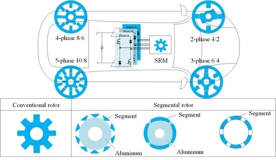
1. Introduction
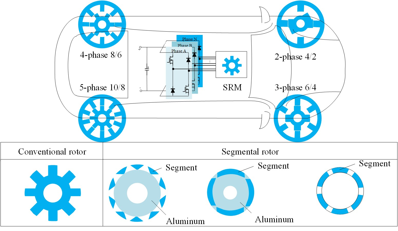
2. Conventional Switched Reluctance Motor
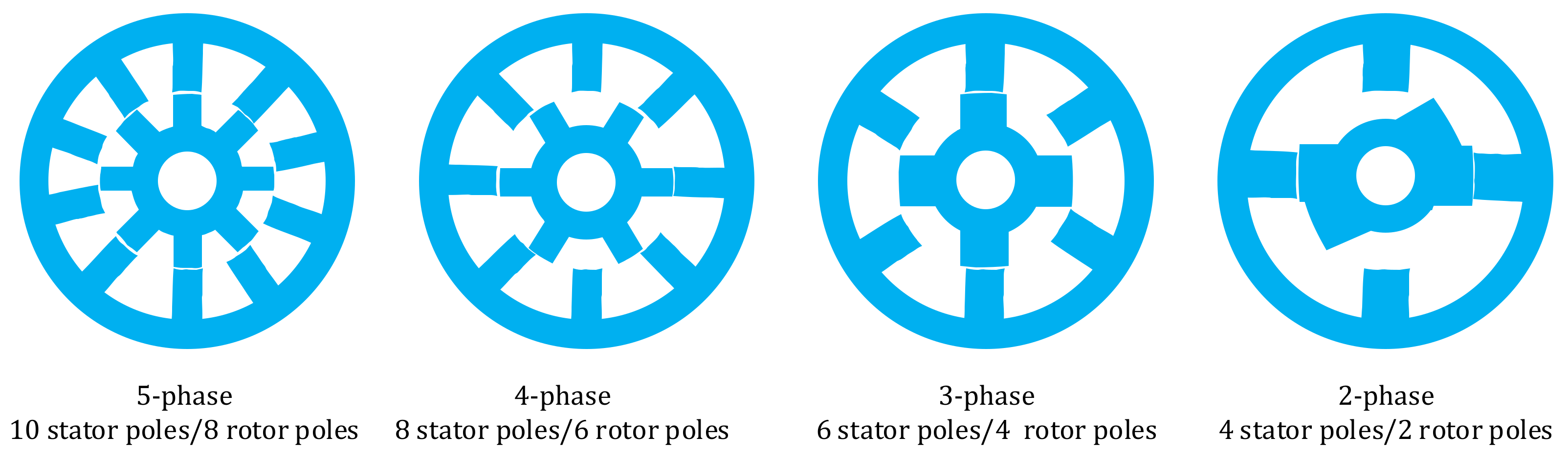
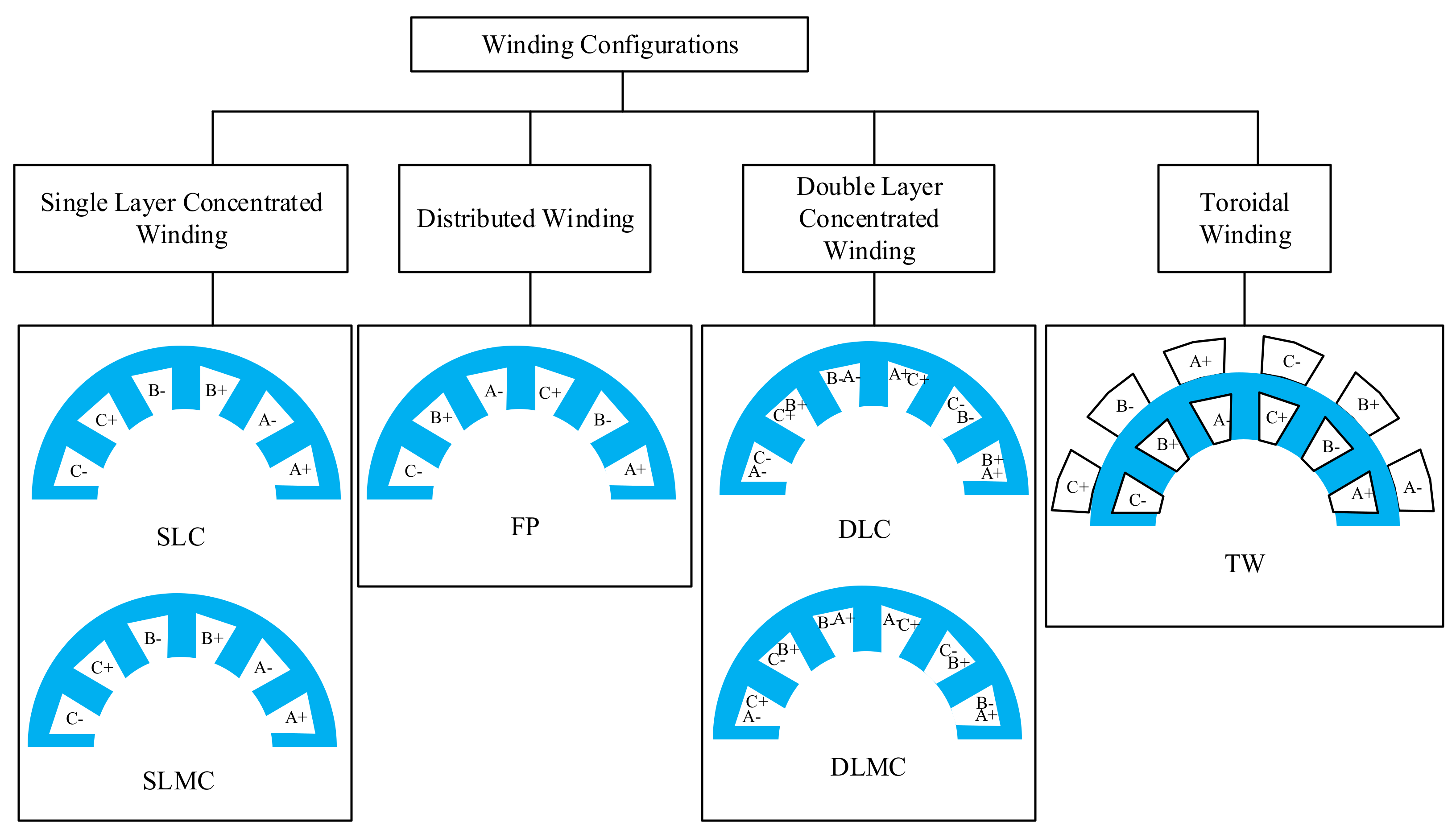
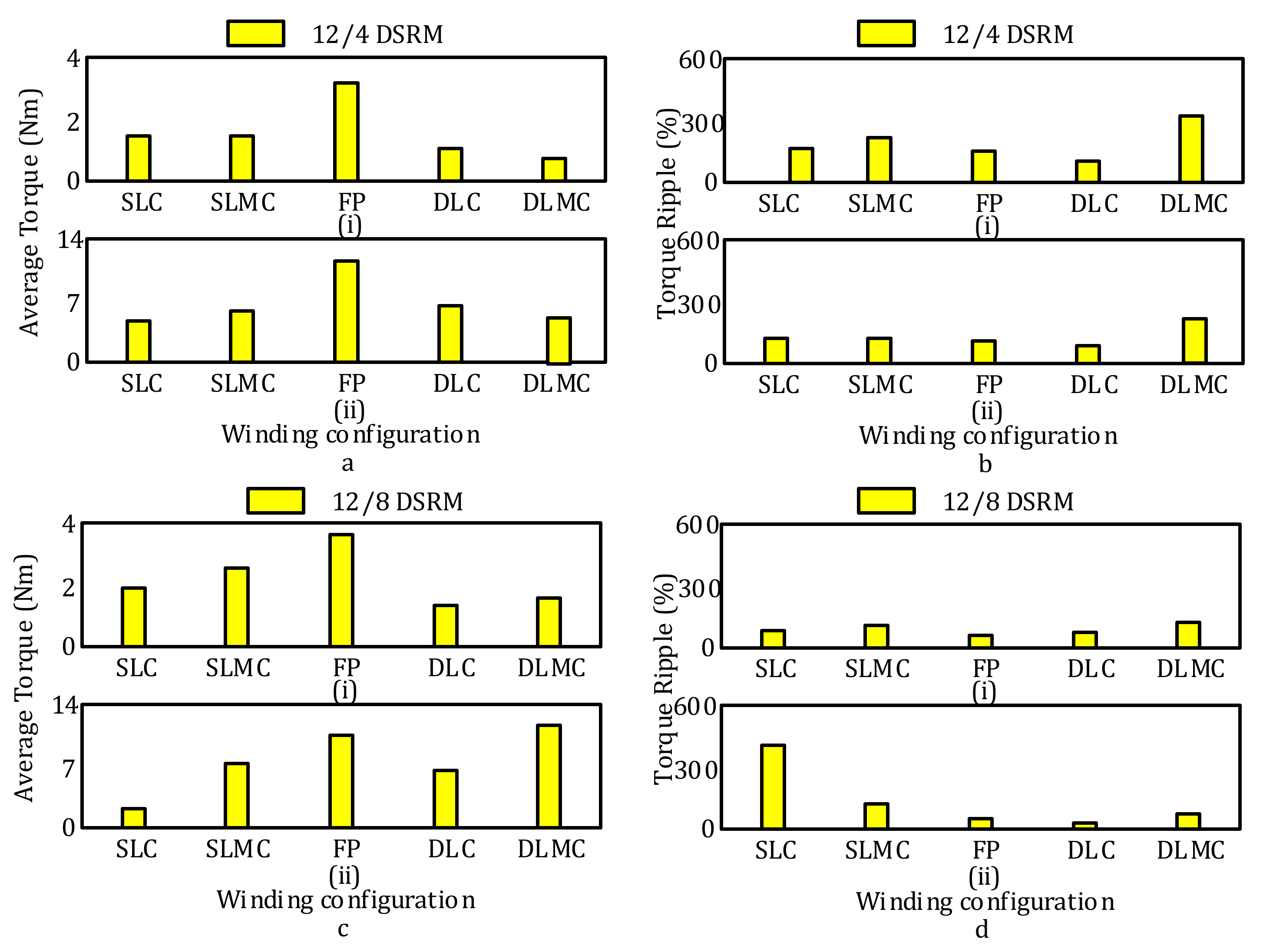
2.1. Winding Configurations
2.2. One-Stack Structure Conventional SRM
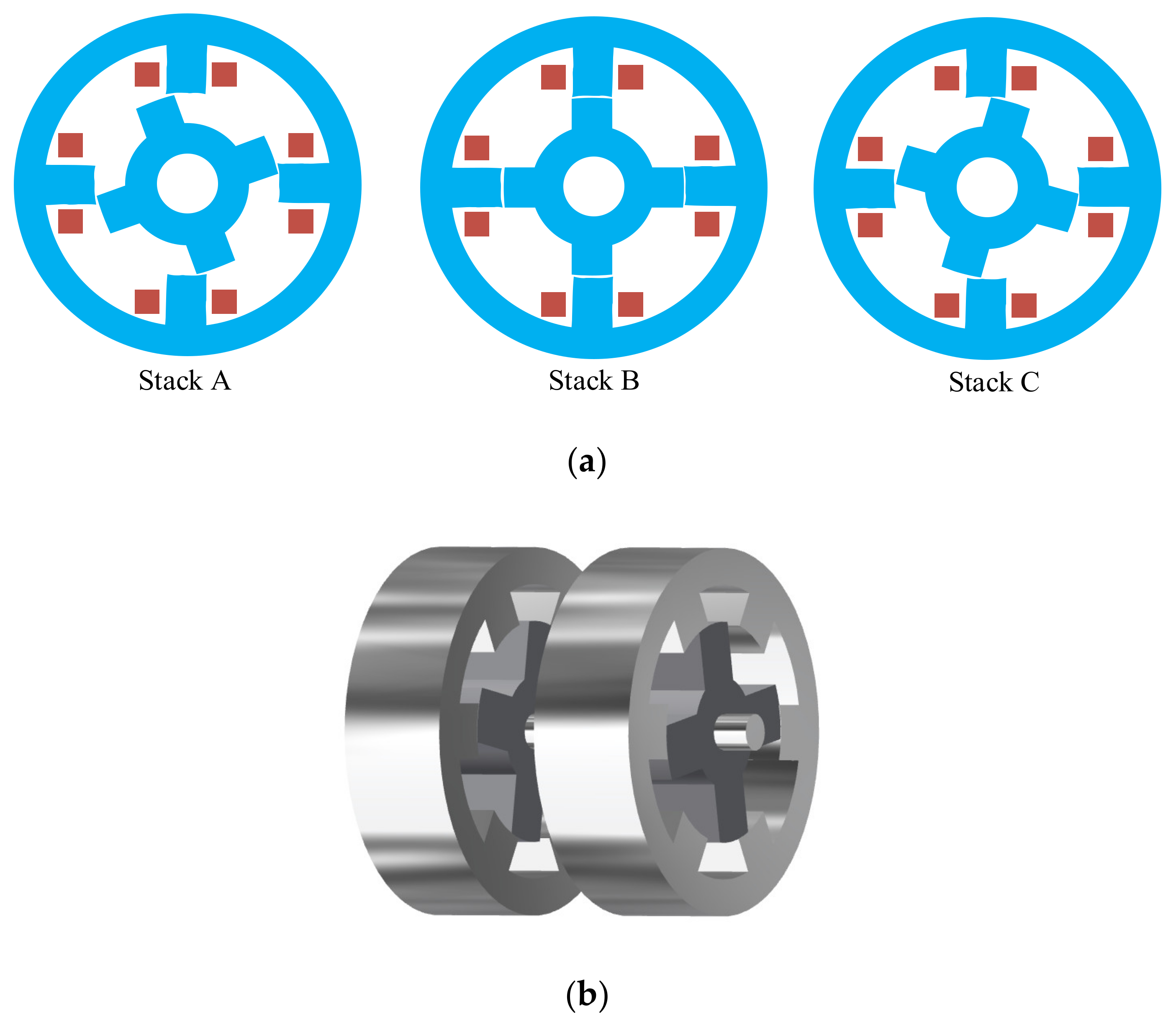
2.3. Multi-Stack and Multi-Layer Structure Conventional SRM
2.4. Summary and Comparison of Conventional SRMs
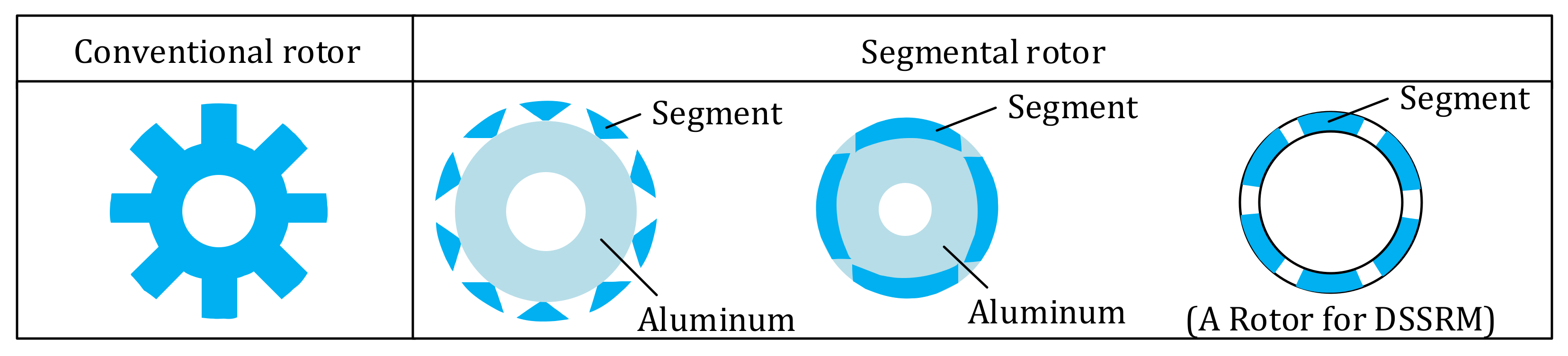
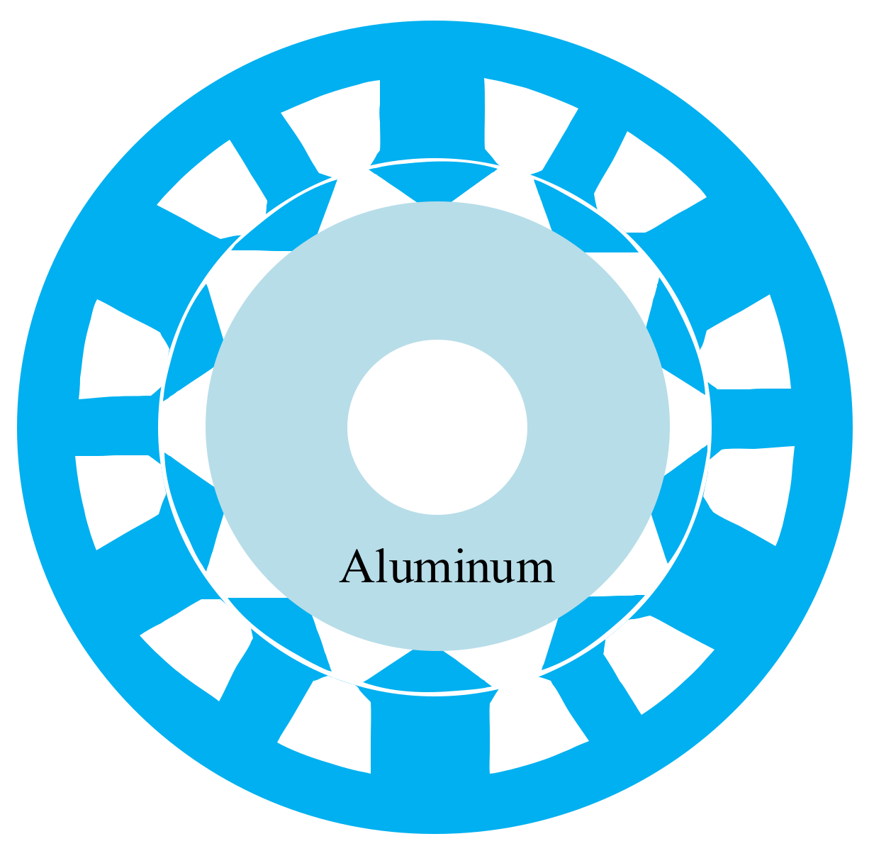
3. Segmental Switched Reluctance Motor
3.1. One-Stack Structure of the segSRM
3.2. Multi-Stack and Multi-Layer Structure Segmental SRM
3.3. Summary and Comparison of Segmental Structures
4. Drive of the SRM
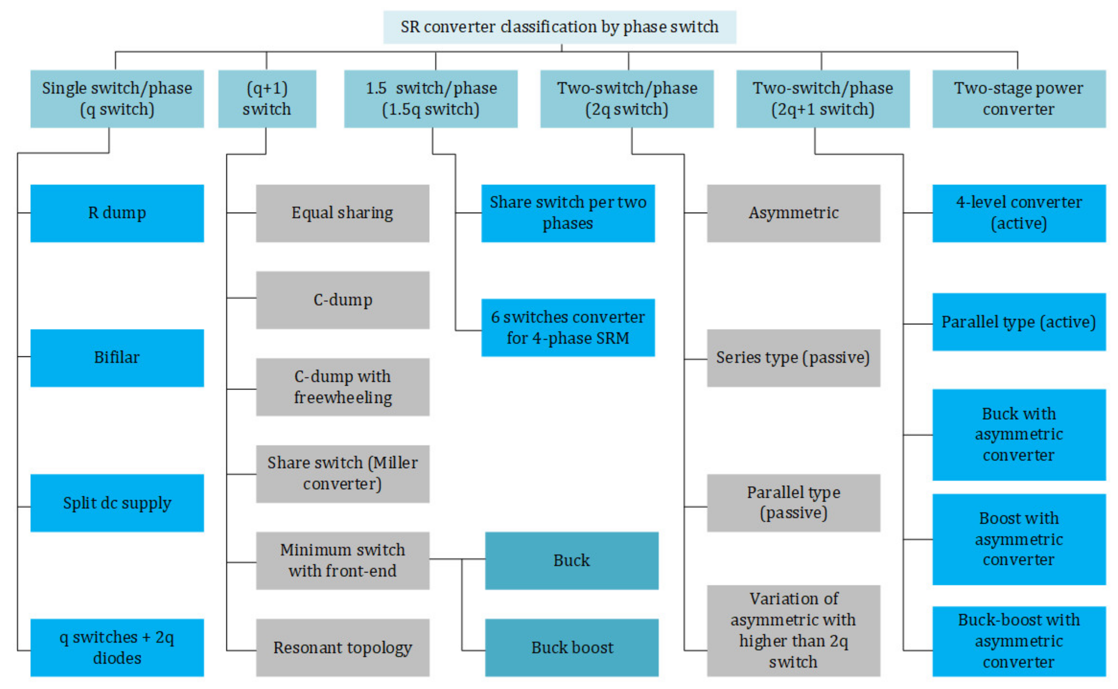
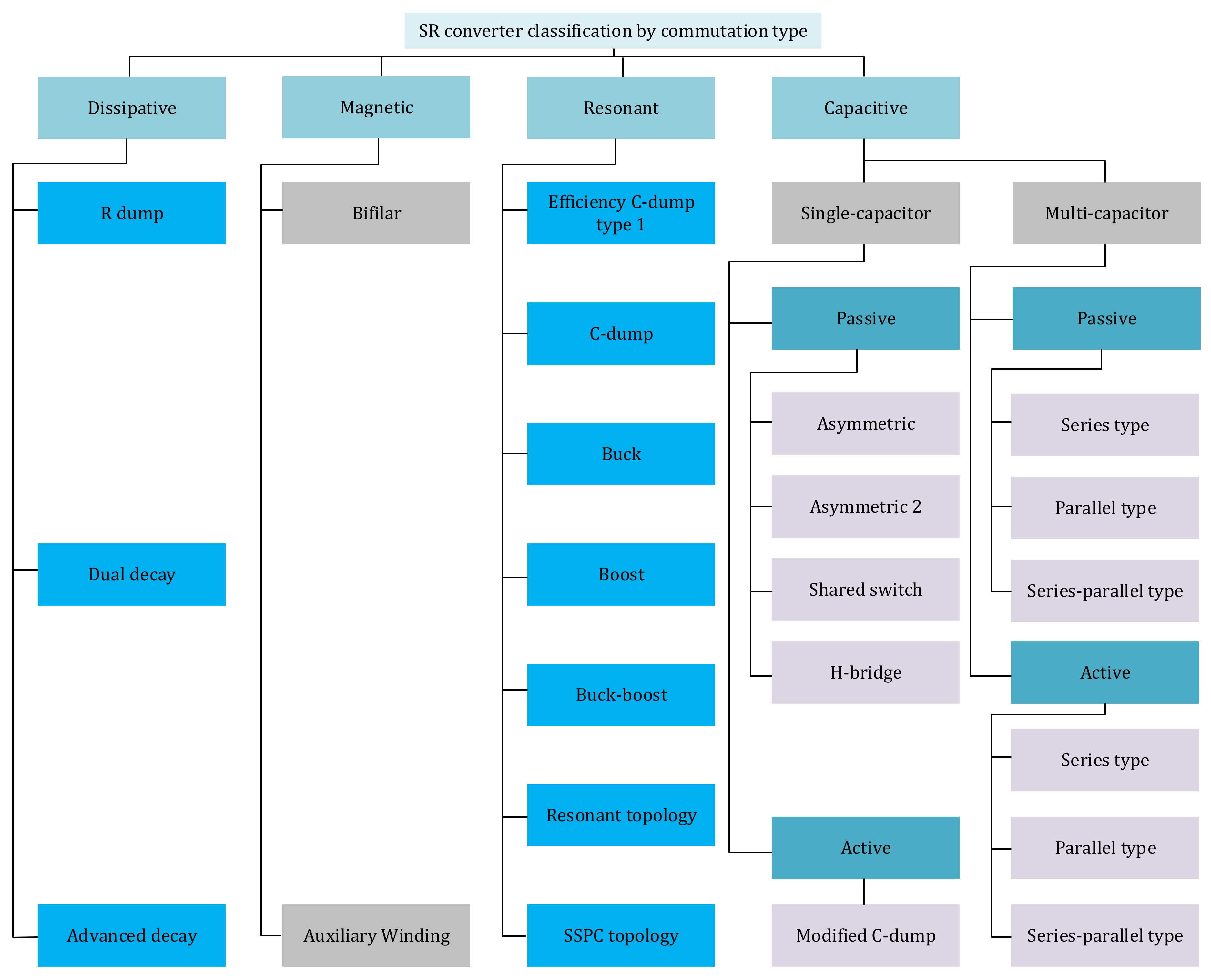
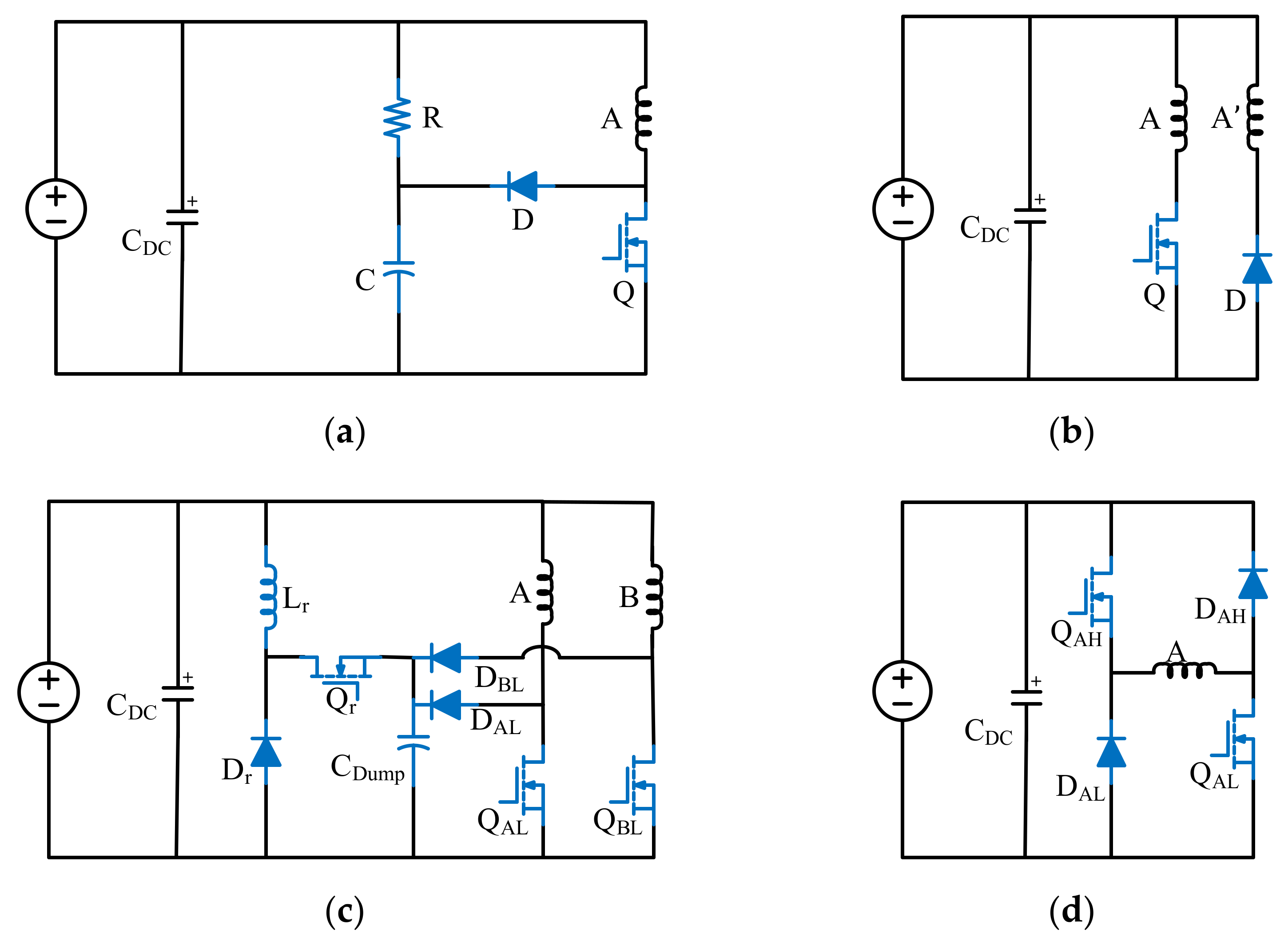
4.1. Conventional Converters for SRMs
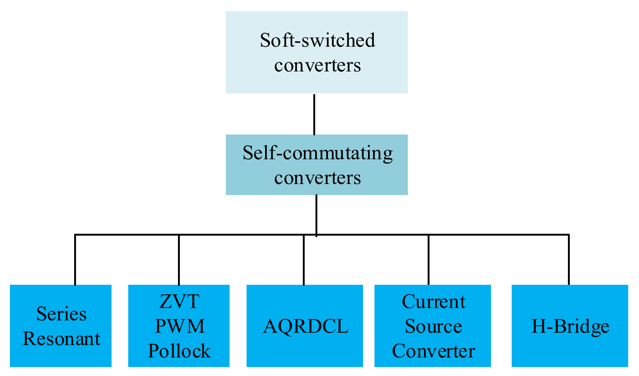
4.2. Soft-Switching Converters for the SRM
4.3. SRM Drive with Three-Phase Standard Six-Switch Inverter
4.4. Integrated EV Battery Chargers for the SRM
5. SRM Control Methods
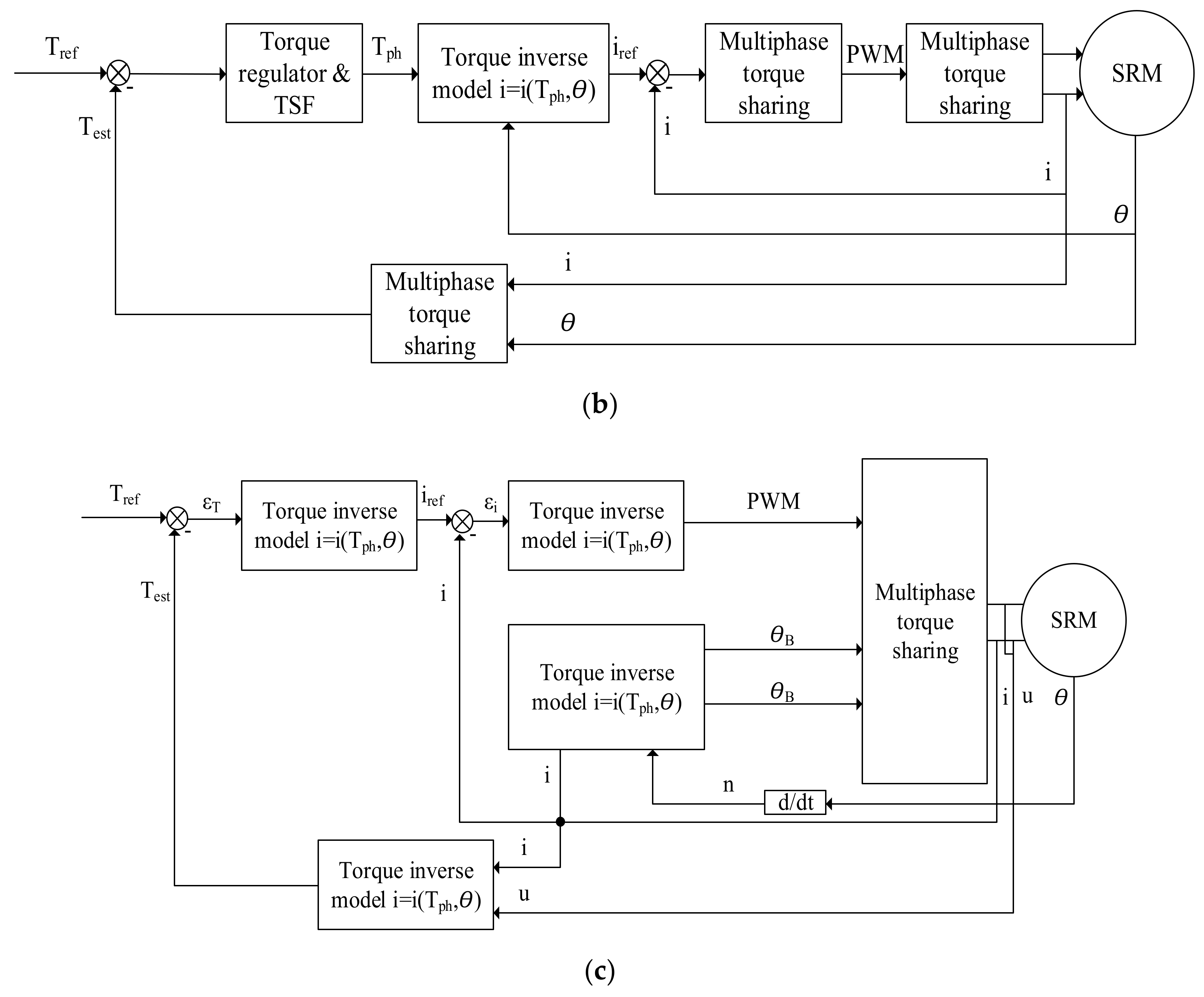
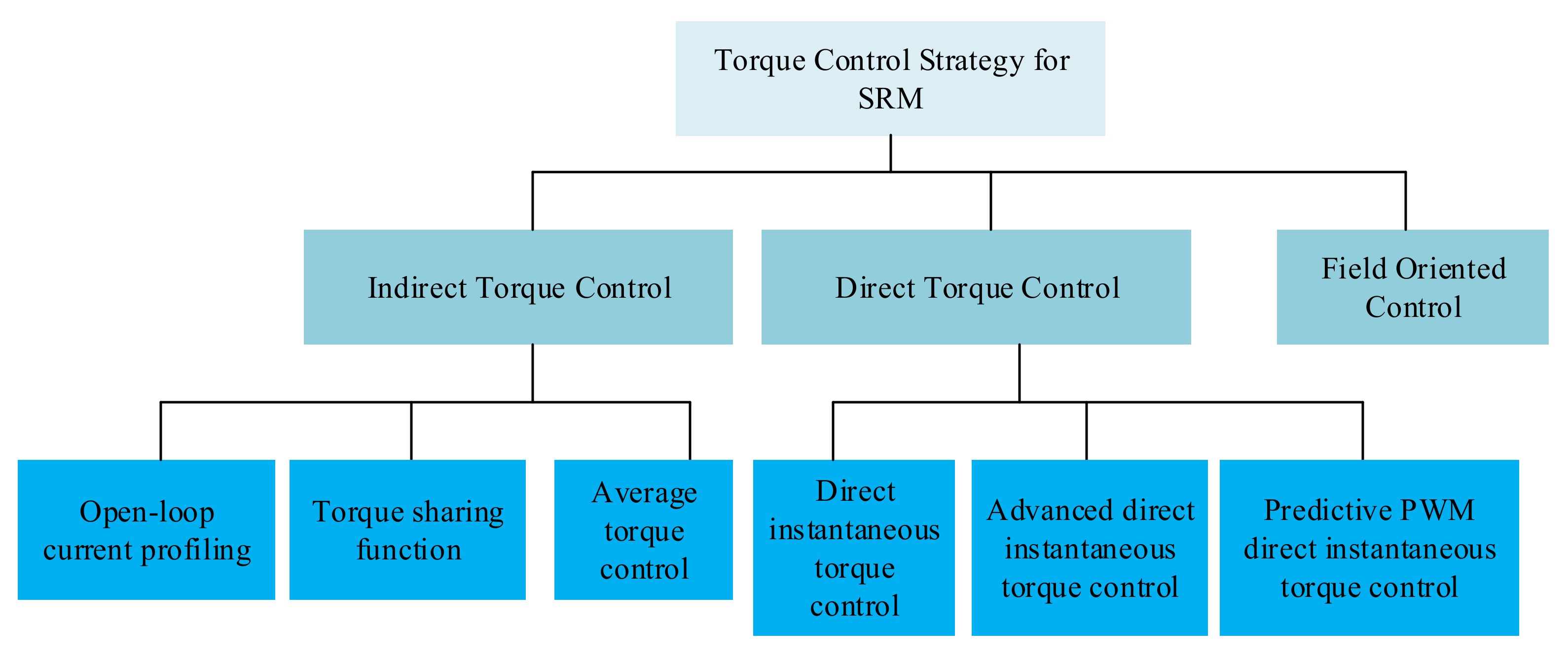
5.1. Control Method for Torque Ripple Reduction
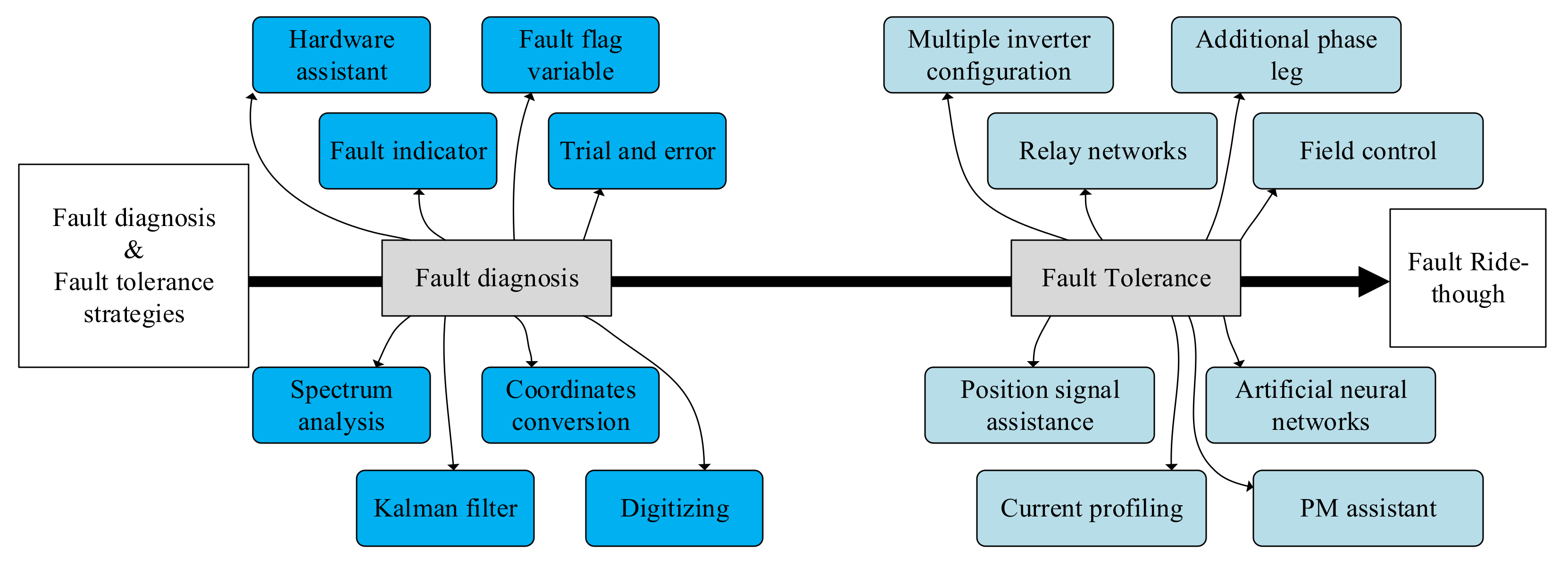
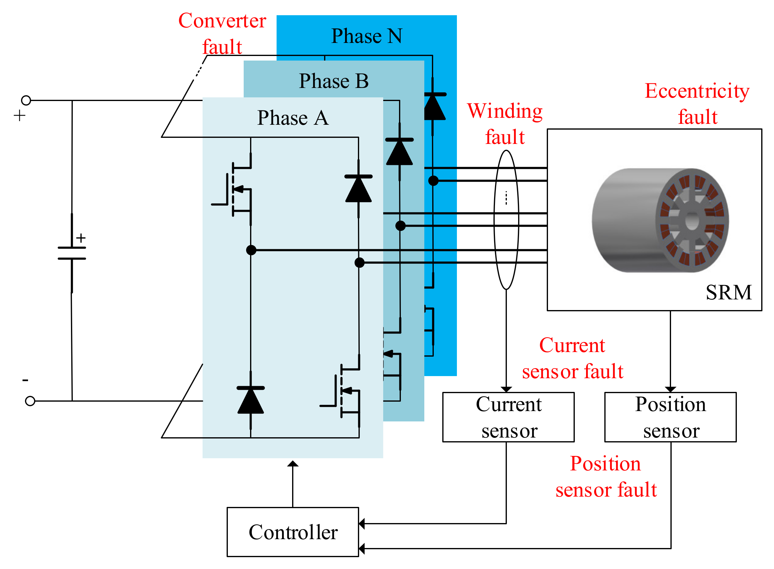
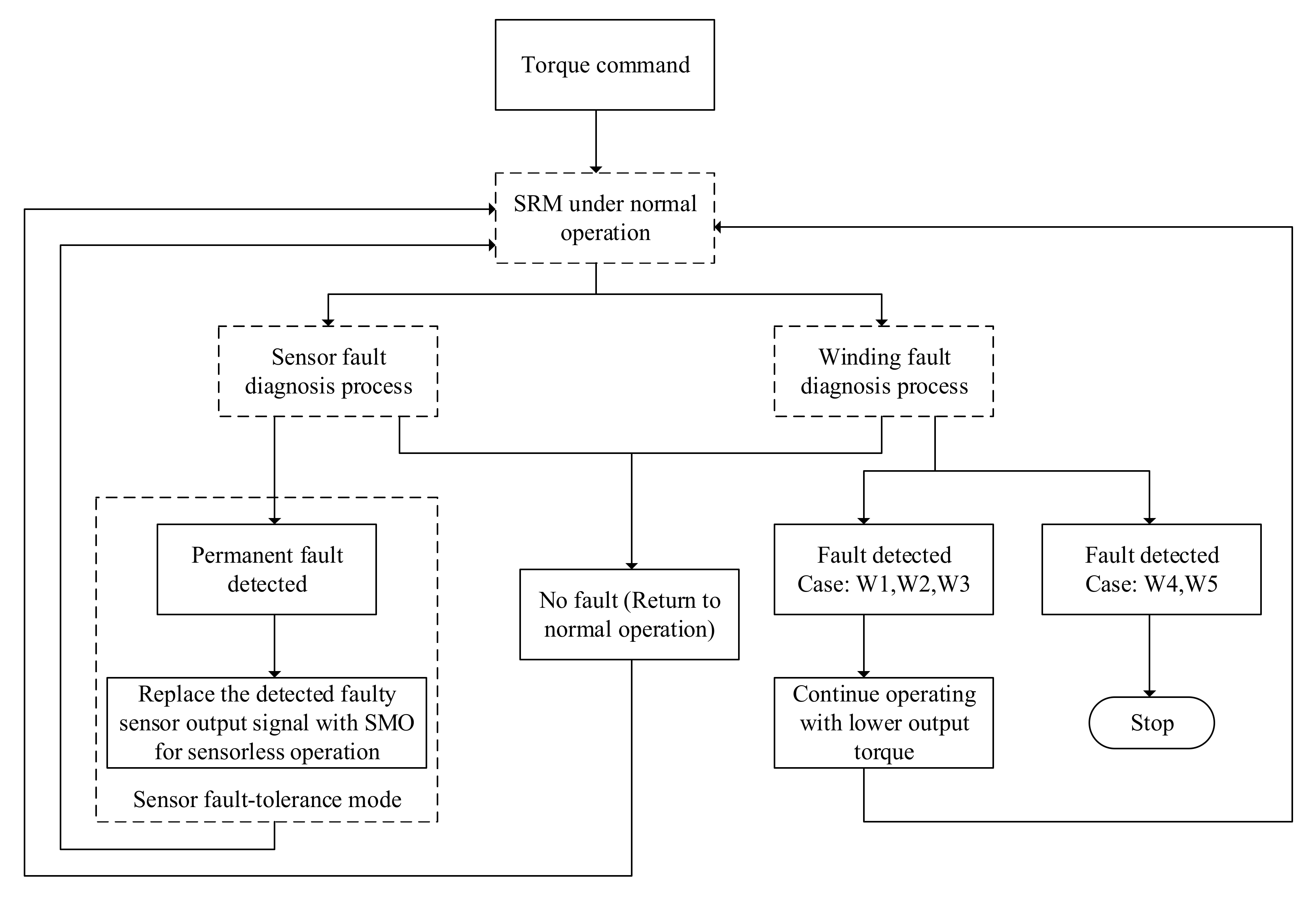
5.2. Fault-Diagnosis and Fault-Tolerance Techniques
5.3. Sensorless Control of the SRMs
6. Conclusions and Future Trends
- (1)
- The reduction of the torque ripple should be achieved by developing the multi-stack conventional SRM with less number of switches.
- (2)
- The torque ripple should be reduced with the multi-stack segSRM with simple topology.
- (3)
- The drive for the SRMs needs to reach both lower losses and less switches and so should be further developed.
- (4)
- The control methods to reduce the torque ripple of the SRMs are to be advanced further.
- (5)
- The fault-diagnosis and the fault-tolerance techniques with simpler and more efficient algorithms should be developed.
Author Contributions
Funding
Acknowledgments
Conflicts of Interest
Abbreviations
| SRM | switched reluctance motor |
| EV | electric vehicle |
| MSCSRM | multi-stack conventional switched reluctance motors |
| MSSRM-SR | multi-stack switched reluctance motors with a segmental rotor |
| SLC | single-layer concentrated winding |
| SLMC | single layer mutually coupled winding |
| DLC | double layer concentrated winding |
| DLMC | double layer mutually coupled winding |
| FP | fully-pitched winding |
| IM | induction motor |
| PMSM | permanent magnet synchronous motor |
| VSI | voltage source inverter |
| CSRM | conventional SRM |
| EMF | electromotive force |
| HEV | hybrid EV |
| AC | alternating current |
| MIFP | multiple isolated flux |
| TWSRM | toroidal winding SRM |
| MMF | magnetomotive force |
| FEA | finite element analysis |
| DSRM | doubly salient reluctance machine |
| UMF | unbalanced magnetic force |
| SRG | switched reluctance generator |
| DLPISRM | double-layer-per-phase isolated SRM |
| DSSRM | double-stator switched reluctance machine |
| segSRM | segmental SRM |
| SR | switched reluctance |
| LOLE | loss of load expectation |
| PoF | physics of failure |
| ZVT | zero-voltage transition |
| AQRDCL | auxiliary quasi-resonant DC-link |
| IPM | intelligent power module |
| BLIL | bridgeless interleaved |
| PV | photovoltaic |
| MPPT | maximum power point tracking |
| A + HB | asymmetric bridge and half bridge |
| NIPC | novel integrated power converter |
| AHBPC | asymmetric half-bridge power converter |
| MMC | modular multilevel converter |
| BESS | battery energy storage system |
| PFC | power factor correction |
| DITC | direct instantaneous torque control |
| ADITC | advanced direct instantaneous torque control |
| TSF | torque sharing function |
| FOC | field-oriented control |
| ARCFL | absolute value of the rate of change of flux linkage |
| TRFS | torque-ripple-free speed |
| SPWPS | solar-powered water pumping system |
| THD | total harmonic distortion |
| GA | genetic algorithm |
| SMO | sliding mode observer |
| ATC | average torque control |
| DTC | direct torque control |
| SMO | sliding mode observer |
References
- Husain, I. Minimization of torque ripple in SRM drives. IEEE Trans. Ind. Electron. 2002, 49, 28–39. [Google Scholar] [CrossRef]
- Beno, M.M.; Marimuthu, N.; Singh, N.A. Improving power factor in switched reluctance motor drive system by optimising the switching angles. In Proceedings of the TENCON 2008 IEEE Region 10 Conference, Hyderabad, India, 19–21 November 2008; pp. 1–5. [Google Scholar]
- Bostanci, E.; Moallem, M.; Parsapour, A.; Fahimi, B. Opportunities and challenges of switched reluctance motor drives for electric propulsion: A comparative study. IEEE Trans. Transp. Electrif. 2017, 3, 58–75. [Google Scholar] [CrossRef]
- Gan, C.; Wu, J.; Sun, Q.; Kong, W.; Li, H.; Hu, Y. A review on machine topologies and control techniques for low-noise switched reluctance motors in electric vehicle applications. IEEE Access 2018, 6, 31430–31443. [Google Scholar] [CrossRef]
- Torkaman, H.; Afjei, E.; Toulabi, M.S. New double-layer-per-phase isolated switched reluctance motor: Concept, numerical analysis, and experimental confirmation. IEEE Trans. Ind. Electron. 2012, 59, 830–838. [Google Scholar] [CrossRef]
- Sun, C.; Zhuang, P.; Li, J.; Li, J. Design and analysis of a 16/6 bearingless switched reluctance motor with segment hybrid rotor teeth. IEEJ Trans. Electr. Electron. Eng. 2020, 15, 939–946. [Google Scholar] [CrossRef]
- Polat, M.; Yildiz, A. Influence of different pole head shapes on motor performance in switched reluctance motors. Adv. Electr. Comput. Eng. 2020, 20, 75–82. [Google Scholar] [CrossRef]
- Siadatan, A.; Fatahi, N.; Sedaghat, M. Optimum designed multilayer switched reluctance motors for use in electric vehicles to increase efficiency. In Proceedings of the 2018 International Symposium on Power Electronics, Electrical Drives, Automation and Motion (SPEEDAM), Amalfi, Italy, 20–22 June 2018; pp. 304–308. [Google Scholar]
- Miller, T.J.E. Switched Reluctance Motors and Their Control; Magna Physics: Hillsboro, OH, USA; Clarendon Press: Oxford, UK, 1993. [Google Scholar]
- Gan, C.; Chen, Y.; Qu, R.; Yu, Z.; Kong, W.; Hu, Y. An overview of fault-diagnosis and fault-tolerance techniques for switched reluctance machine systems. IEEE Access 2019, 7, 174822–174838. [Google Scholar] [CrossRef]
- Argiolas, O.; Nazeraj, E.; Hegazy, O.; De Backer, J.; Mohammadi, A.; Van Mierlo, J. Design optimization of a 12/8 Switched Reluctance Motor for electric and hybrid vehicles. In Proceedings of the 2017 12th International Conference on Ecological Vehicles and Renewable Energies, EVER 2017, Monte Carlo, Monaco, 11–13 April 2017. [Google Scholar] [CrossRef]
- Industrail_sr_Brochure. Available online: https://acim.nidec.com/motors/usmotors/-/media/usmotors/documents/literature/brochures/industrial_sr_brochure.ashx (accessed on 20 March 2021).
- Kehui Motor Brochure. Available online: https://www.kehui.com/wp-content/uploads/2018/02/Kehui_motor_brochure.pdf (accessed on 20 March 2021).
- Rocky Mountain Technologies INC. Available online: http://www.rockymountaintechnologies.com/Standard%20Products.html# (accessed on 20 March 2021).
- MACCON: Switched Reluctance Motor/Synchronous Reluctance Motor. Available online: https://www.maccon.com/switched-reluctance-motor-synchronous-reluctance-motor.html (accessed on 20 March 2021).
- Striatech. Available online: https://striatech.mybigcommerce.com/ (accessed on 20 March 2021).
- Ma, X.; Li, G.; Zhu, Z.; Jewell, G.W.; Green, J. Investigation on synchronous reluctance machines with different rotor topologies and winding configurations. IET Electr. Power Appl. 2018, 12, 45–53. [Google Scholar] [CrossRef]
- Dong, J.; Howey, B.; Danen, B.; Lin, J.; Jiang, J.W.; Bilgin, B.; Emadi, A. Advanced dynamic modeling of three-phase mutually coupled switched reluctance machine. IEEE Trans. Energy Convers. 2018, 33, 146–154. [Google Scholar] [CrossRef] [Green Version]
- Azer, P.; Bilgin, B.; Emadi, A. Mutually coupled switched reluctance motor: Fundamentals, control, modeling, state of the art review and future trends. IEEE Access 2019, 7, 100099–100112. [Google Scholar] [CrossRef]
- Burress, T.; Ayers, C. Development and experimental characterization of a Multiple Isolated Flux Path reluctance machine. In Proceedings of the 2012 IEEE Energy Conversion Congress and Exposition (ECCE), Raleigh, NC, USA, 15–20 September 2012. [Google Scholar]
- Husain, T.; Uddin, W.; Sozer, Y. Performance comparison of short-pitched and fully pitched switched reluctance machines over wide speed operations. IEEE Trans. Ind. Appl. 2018, 54, 4278–4287. [Google Scholar] [CrossRef]
- Zuo, S.; Liu, Z.; Hu, S. Influence of rotor eccentricity on radial electromagnetic force characteristics in switched reluctance motors and compensation. Electr. Power Compon. Syst. 2020, 48, 388–398. [Google Scholar] [CrossRef]
- Yu, Z.; Gan, C.; Chen, Y.; Qu, R. DC-biased sinusoidal current excited switched reluctance motor drives based on flux modulation principle. IEEE Trans. Power Electron. 2020, 35, 10614–10628. [Google Scholar] [CrossRef]
- Song, S.; Fang, G.; Hei, R.; Jiang, J.; Ma, R.; Liu, W. Torque ripple and efficiency online optimization of switched reluctance machine based on torque per ampere characteristics. IEEE Trans. Power Electron. 2020, 35, 9608–9616. [Google Scholar] [CrossRef]
- Gan, C.; Chen, Y.; Cui, X.; Sun, J.; Ni, K.; Qu, R. Investigation of rotor strength and rotor dynamics for high-speed high-power switched reluctance machines. IET Electr. Power Appl. 2020, 14, 1624–1630. [Google Scholar] [CrossRef]
- Diao, K.; Sun, X.; Lei, G.; Guo, Y.; Zhu, J. Multiobjective system level optimization method for switched reluctance motor drive systems using finite-element model. IEEE Trans. Ind. Electron. 2020, 67, 10055–10064. [Google Scholar] [CrossRef]
- Fan, J.; Lee, Y. Design consideration to achieve wide-speed-range operation in a switched reluctance motor. Can. J. Electr. Comput. Eng. 2020, 43, 290–294. [Google Scholar] [CrossRef]
- Kucuk, F.; Nakamura, T. Low-cost permanent magnet-assisted switched reluctance motor for adjustable speed drive applications. IEEJ Trans. Electr. Electron. Eng. 2020, 15, 1213–1218. [Google Scholar] [CrossRef]
- Siadatan, A.; Najmi, V.; Asgar, M.; Afjei, E. A new 6/4 two layers switched reluctance motor: Concept, simulation and analysis. In Proceedings of the International Aegean Conference on Electrical Machines and Power Electronics, ACEMP 2011 and Electromotion 2011 Joint Conference, Istanbul, Turkey, 8 September 2011; pp. 244–249. [Google Scholar] [CrossRef]
- Daldaban, F.; Ustkoyuncu, N. Multi-layer switched reluctance motor to reduce torque ripple. Energy Convers. Manag. 2008, 49, 974–979. [Google Scholar] [CrossRef]
- Afjei, E.; Torkaman, H.; Mazloomnezhad, B. A new double layer per phase configuration for switched reluctance motor. In Proceedings of the 2010 IEEE International Conference on Power and Energy, Kuala Lumpur, Malaysia, 29 November–1 December 2010; pp. 222–225. [Google Scholar] [CrossRef]
- Siadatan, A.; Najmi, V.; Afjei, E. A novel 4/4 Multilayer Switched Reluctance Motor with 4 magnetically independent layers. In Proceedings of the International Aegean Conference on Electrical Machines and Power Electronics, ACEMP 2011 and Electromotion 2011 Joint Conference, Istanbul, Turkey, 8–10 September 2011; pp. 255–259. [Google Scholar] [CrossRef]
- Afjei, E.; Siadatan, A.; Asgar, M. Comparison between two field-assisted switched reluctance generators suitable for wind turbine applications. In Proceedings of the 2011 International Conference on Clean Electrical Power (ICCEP), Ischia, Italy, 14–16 June 2011; pp. 272–276. [Google Scholar] [CrossRef]
- Najmi, V.; Siadatan, A.; Asgar, M.; Afjei, E. Magnetostatic analysis of a novel three phase 6/4 two layer field-assisted Switched Reluctance Generator. In Proceedings of the International Aegean Conference on Electrical Machines and Power Electronics, ACEMP 2011 and Electromotion 2011 Joint Conference, Istanbul, Turkey, 8–10 September 2011; pp. 266–269. [Google Scholar] [CrossRef]
- Jahanmahin, M.; Hajihosseinlu, A.; Afjei, E.; Siadatan, A.; Tavakoli, A. A novel multilayer 8 by 4 switch reluctance machine with ripple reduction. In Proceedings of the International Symposium on Power Electronics Power Electronics, Electrical Drives, Automation and Motion, Virtual, Sorrento, Italy, 24–26 June 2020; pp. 536–540. [Google Scholar]
- Najmi, V.; Siadatan, A.; Afjei, E. Analysis of 8/6 two-layer switched reluctance motor with rotor shifting technique for servo applications. In Proceedings of the 2012 3rd Power Electronics and Drive Systems Technology, PEDSTC 2012, Tehran, Iran, 15–16 February 2012; pp. 273–277. [Google Scholar] [CrossRef]
- Salimi, A.; Rezazadeh, G.; Nourollah, S.; Niassati, N.; Hajihosseinlu, A. A novel four layer switch reluctance generator. In Proceedings of the 2012 15th International Power Electronics and Motion Control Conference (EPE/PEMC), Novi Sad, Serbia, 4–6 September 2012; p. LS1b.2-1. [Google Scholar]
- Hajihosseinlu, A.; Jahanmahin, M.; Afjei, E.; Tajik, S. A novel four layer switch reluctance motor with high torque and ripple reduction. In Proceedings of the 2012 3rd Power Electronics and Drive Systems Technology, PEDSTC 2012, Tehran, Iran, 15–16 February 2012; pp. 62–67. [Google Scholar] [CrossRef]
- Siadatan, A.; Rafiee, M.; Afjei, E. Design, analysis and controlling of a novel 4 by 4 multilayer SRM. In Proceedings of the 2013 21st Iranian Conference on Electrical Engineering (ICEE), Mashhad, Iran, 14–16 May 2013; pp. 1–5. [Google Scholar] [CrossRef]
- Siadatan, A.; Afjei, E.; Torkaman, H.; Rafie, M. Design, simulation and experimental results for a novel type of two-layer 6/4 three-phase switched reluctance motor/generator. Energy Convers. Manag. 2013, 71, 199–207. [Google Scholar] [CrossRef]
- Sugiura, M.; Ishihara, Y.; Ishikawa, H.; Naitoh, H. Improvement of efficiency by stepped-skewing rotor for switched reluctance motors. In Proceedings of the 2014 International Power Electronics Conference (IPEC-Hiroshima 2014—ECCE ASIA), Hiroshima, Japan, 18–21 May 2014; pp. 1135–1140. [Google Scholar] [CrossRef]
- Siadatan, A.; Afjei, E.; Mahmoodi, M.M. Torque comparison between a novel Multilayer Switched Reluctance Motor and a custom one. In Proceedings of the 2014 International Symposium on Power Electronics, Electrical Drives, Automation and Motion, Ischia, Italy, 18–20 June 2014; pp. 409–416. [Google Scholar] [CrossRef]
- Siadatan, A.; Torkaman, H.; Afjei, E. Septi-segment switched reluctance machine: Design, modeling, and manufacturing. Int. Trans. Electr. Energy Syst. 2016, 26, 1673–1684. [Google Scholar] [CrossRef]
- Gu, L.; Wang, W.; Fahimi, B.; Clark, A.; Hearron, J. Magnetic design of two-phase switched reluctance motor with bidirectional startup capability. IEEE Trans. Ind. Appl. 2016, 52, 2148–2155. [Google Scholar] [CrossRef]
- Hekmati, P.; Brown, I.P. Rotary-reciprocating movement switched-reluctance machines with consequent axially shifted poles. IEEE Trans. Magn. 2018, 54, 1–10. [Google Scholar] [CrossRef]
- Siadatan, A.; Najmi, V.; Afjei, E. Modeling, simulation and analysis of a novel two layer 8/6 hybrid switched reluctance motor/field-assisted generator. In Proceedings of the 2012 20th Iranian Conference on Electrical Engineering (ICEE2012), Tehran, Iran, 15-17 May 2012; IEEE, 2012; pp. 495–500. [Google Scholar] [CrossRef]
- Kondelaji, M.A.J.; Mirsalim, M. Non-linear modeling of a multi-layer switched reluctance motor with magnetically-disconnected stator modules. In Proceedings of the 2019 10th International Power Electronics, Drive Systems and Technologies Conference (PEDSTC), Shiraz, Iran, 12–14 February 2019; pp. 1–6. [Google Scholar] [CrossRef]
- Vahedi, P.; Ganji, B.; Afjei, E. Multi-layer switched reluctance motors: Performance prediction and torque ripple reduction. Int. Trans. Electr. Energy Syst. 2019, 30. [Google Scholar] [CrossRef]
- Luk, P.C.K.; Jinupun, K.P. Direct work control for a three-stack switched reluctance motor. In Proceedings of the 2005 IEEE 36th Power Electronics Specialists Conference, Recife, Brazil, 12–16 June 2005; IEEE, 2006; pp. 2462–2466. [Google Scholar]
- Vatani, M.; Mirsalim, M.; Vaez-Zadeh, S. A New double-layer switched reluctance motor with a low torque ripple. In Proceedings of the 2019 27th Iranian Conference on Electrical Engineering (ICEE), Yazd, Iran, 30 April–2 May 2019; pp. 792–797. [Google Scholar]
- Mecrow, B.; Finch, J.; El-Kharashi, E.; Jack, A. Switched reluctance motors with segmental rotors. IEE Proc. Electr. Power Appl. 2002, 149, 245. [Google Scholar] [CrossRef]
- Mecrow, B.; El-Kharashi, E.; Finch, J.; Jack, A. Segmental rotor switched reluctance motors with single-tooth windings. IEE Proc. Electr. Power Appl. 2003, 150, 591. [Google Scholar] [CrossRef]
- Abbasian, M.; Moallem, M.; Fahimi, B. Double-Stator Switched Reluctance Machines (DSSRM): Fundamentals and magnetic force analysis. IEEE Trans. Energy Convers. 2010, 25, 589–597. [Google Scholar] [CrossRef]
- Bostanci, E.; Gu, L.; Cosoroaba, E.; Moallem, M.; Fahimi, B. Performance improvement and comparison of concentrated winding segmental rotor and double stator switched reluctance machines. In Proceedings of the 2016 IEEE Conference on Electromagnetic Field Computation (CEFC), Miami, FL, USA, 13–16 November 2016; p. 1. [Google Scholar]
- Oyama, J.; Higuchi, T.; Abe, T.; Kifuji, N. Novel switched reluctance motor with segment core embedded in aluminum rotor block. IEEJ Trans. Ind. Appl. 2006, 126, 385–390. [Google Scholar] [CrossRef] [Green Version]
- Deng, X.; Mecrow, B. A comparison of conventional and segmental rotor 12/10 switched reluctance motors. In Proceedings of the 2019 IEEE International Electric Machines and Drives Conference, IEMDC 2019, San Diego, CA, USA, 12–15 May 2019; pp. 1508–1513. [Google Scholar] [CrossRef] [Green Version]
- Chen, L.; Wang, H.; Sun, X.; Cai, Y.; Li, K.; Diao, K.; Wu, J. Development of a digital control system for a belt-driven starter generator segmented switched reluctance motor for hybrid electric vehicles. Proc. Inst. Mech. Eng. Part I J. Syst. Control Eng. 2020, 234, 975–984. [Google Scholar] [CrossRef]
- Abdollahi, M.; Mirsalim, M. Novel E-Core Double-Stator Two Phase Switched Reluctance Motor with Segmental Rotor. In Proceedings of the 2019 10th International Power Electronics, Drive Systems and Technologies Conference (PEDSTC), Shiraz, Iran, 12–14 February 2019; pp. 72–77. [Google Scholar] [CrossRef]
- Higuchi, T.; Ueda, T.; Abe, T. Torque ripple reduction control of a novel segment type SRM with 2-steps slide rotor. In Proceedings of the 2010 International Power Electronics Conference—ECCE ASIA, Sapporo, Japan, 21–24 June 2010; pp. 2175–2180. [Google Scholar] [CrossRef]
- Higuchi, T.; Nakao, Y.; Abe, T. Characteristics of a novel segment type SRM with 2-step slide rotor. In Proceedings of the 2009 International Conference on Electrical Machines and Systems, Tokyo, Japan, 15–18 November 2009; pp. 1–4. [Google Scholar] [CrossRef]
- Lan, Y.; Peng, W.; Aksoz, A.; Benomar, Y.; Bossche, P.V.D.; El, M.; Hegazy, O. Design and Modelling of 12/4 Fully-Pitched Segmental Switched Reluctance Motors. In Proceedings of the 2020 Fifteenth International Conference on Ecological Vehicles and Renewable Energies (EVER), Monte-Carlo, Monaco, 10–12 September 2020. [Google Scholar]
- Mecrow, B.; El-Kharashi, E.; Finch, J.; Jack, A. Preliminary performance evaluation of switched reluctance motors with segmental rotors. IEEE Trans. Energy Convers. 2004, 19, 679–686. [Google Scholar] [CrossRef]
- Mukhopadhyay, J.; Sengupta, S.; Choudhuri, S. Drive strategies for switched reluctance motor—A review. In Proceedings of the Michael Faraday IET International Summit 2015, Kolkata, India, 12–13 September 2015; Volume 23. [Google Scholar] [CrossRef]
- Ahn, J.-W.; Liang, J.; Lee, D.-H. Classification and analysis of switched reluctance converters. J. Electr. Eng. Technol. 2010, 5, 571–579. [Google Scholar] [CrossRef] [Green Version]
- Krishnan, R. Switched reluctance motor drives. In Proceedings of the Industrial Electronics 2017, Siem Reap, Cambodia, 18–20 June 2017. [Google Scholar]
- Pittermann, M.; Fort, J.; Diesl, J.; Pavlicek, V. Converters for Switched Reluctance Motor—Topology Comparison. In Proceedings of the 2018 18th International Conference on Mechatronics—Mechatronika, ME, Brno, Czech Republic, 5–7 December 2018; pp. 1–8. [Google Scholar]
- Peyghami, S.; Davari, P.; Wang, H.; Blaabjerg, F. Reliability and risk assessment in a Power Electronic Based Power System (PEPS): Using non-constant failure rates of converters. In Proceedings of the 2018 20th European Conference on Power Electronics and Applications, EPE 2018 ECCE Europe, Riga, Latvia, 17–21 September 2018. [Google Scholar]
- Maier, R.W.; Bakran, M.M. Switching SiC MOSFETs under conditions of a high power module. In Proceedings of the 2018 20th European Conference on Power Electronics and Applications, EPE 2018 ECCE Europe, Riga, Latvia, 17–21 September 2018; p. 2. [Google Scholar]
- Kiani, E.; Ganji, B.; Taher, S.A. Model predictive control of switched reluctance generator based on Z-source converter for wind power applications. Int. Trans. Electr. Energy Syst. 2020, 30, e12578. [Google Scholar] [CrossRef]
- Jing, J. A Power factor correction buck converter-fed switched reluctance motor with torque ripple suppression. Math. Probl. Eng. 2020, 2020, 6730284. [Google Scholar] [CrossRef]
- Chaple, M.D.; Bodkhe, S.B. An integrated converter model and enhanced control approach for torque ripple minimisation of switched reluctance motor: A CMFG-RNN technique. Int. J. Ambient. Energy 2018, 41, 1142–1153. [Google Scholar] [CrossRef]
- Ellabban, O.; Abu-Rub, H. Switched reluctance motor converter topologies: A review. In Proceedings of the 2014 IEEE International Conference on Industrial Technology (ICIT), Busan, Korea, 26 February–1 March 2014; pp. 840–846. [Google Scholar] [CrossRef]
- Kabir, A.; Husain, I. Hybrid excitation topologies for three-phase mutually coupled reluctance machine with standard inverters. In Proceedings of the 2015 IEEE Power & Energy Society General Meeting, Denver, CO, USA, 26–30 July 2015; pp. 1–5. [Google Scholar] [CrossRef]
- Kabir, M.A.; Husain, I. Concentrated winding segmented rotor switched reluctance machine (SRM) using three-phase standard inverters. In Proceedings of the 2015 IEEE Energy Conversion Congress and Exposition, ECCE 2015, Montreal, QC, Canada, 20–24 September 2015; pp. 5567–5572. [Google Scholar] [CrossRef]
- Kabir, A.; Husain, I. Design of Mutually Coupled Switched Reluctance Motors (MCSRMs) for extended speed applications using 3-phase standard inverters. IEEE Trans. Energy Convers. 2016, 31, 436–445. [Google Scholar] [CrossRef]
- Chen, Q.; Xu, D.; Xu, L.; Wang, J.; Lin, Z.; Zhu, X. Fault-tolerant operation of a novel dual-channel switched reluctance motor using two 3-phase standard inverters. IEEE Trans. Appl. Supercond. 2018, 28, 1–5. [Google Scholar] [CrossRef]
- Subotic, I.; Levi, E. A review of single-phase on-board integrated battery charging topologies for electric vehicles. In Proceedings of the 2015 IEEE Workshop on Electrical Machines Design, Control and Diagnosis (WEMDCD), Torino, Italy, 26–27 March 2015; pp. 136–145. [Google Scholar] [CrossRef]
- Na, T.; Yuan, X.; Tang, J.; Zhang, Q. A Review of on-board integrated charger for electric vehicles and a new solution. In Proceedings of the 2019 IEEE 10th International Symposium on Power Electronics for Distributed Generation Systems (PEDG), Xi’an, China, 3–6 June 2019; pp. 693–699. [Google Scholar]
- Drive, M.; Power, U.T.-P.; Chang, H.-C.; Liaw, C.-M. An Integrated Driving/Charging Switched Reluctance motor drive using three-phase power module. IEEE Trans. Ind. Electron. 2011, 58, 1763–1775. [Google Scholar]
- Huseini, S.R.K.; Farjah, E.; Tashakor, N.; Ghanbari, T. Development of an integrated Switched-Reluctance Motor drive with battery charging capability for electric vehicle propulsion system. In Proceedings of the 6th Power Electronics, Drive Systems & Technologies Conference (PEDSTC2015), Tehran, Iran, 3–4 February 2015; pp. 579–584. [Google Scholar] [CrossRef]
- Jiang, J.; Xia, T. An integrated charger with central-tapped winding switched reluctance motor drive. In Proceedings of the 2017 IEEE 6th International Conference on Renewable Energy Research and Applications (ICRERA), San Diego, CA, USA, 5–8 November 2017; pp. 870–874. [Google Scholar]
- Liang, J.; Li, W.; Song, Z.; Shi, Y. An integrated battery charger base on split-winding switched reluctance motor drive. In Proceedings of the 2016 IEEE Transportation Electrification Conference and Expo, Asia-Pacific (ITEC Asia-Pacific), Busan, Korea, 1–4 June 2016; pp. 106–111. [Google Scholar]
- Deriszadeh, A.; Bojoi, R. An integrated battery-charger for switched reluctance motor drives. In Proceedings of the 2017 6th International Conference on Clean Electrical Power (ICCEP), Liguria, Italy, 27–29 June 2017; pp. 446–451. [Google Scholar] [CrossRef]
- Liang, J.; Sun, T. Design of Integrated Battery Charger Based on Switched Reluctance Motor Drive. In Proceedings of the 2018 21st International Conference on Electrical Machines and Systems (ICEMS), Jeju, Korea, 7–10 October 2018. [Google Scholar]
- Feng, C.; Wu, J.; Sun, Q.; Wu, H.; Zhang, L. An Integrated BLIL Boost Converter-based Switched Reluctance Motor Drive for PEV Applications with PFC Charging Function. In Proceedings of the 2019 22nd International Conference on Electrical Machines and Systems (ICEMS), Harbin, China, 11–14 August 2019; p. 4. [Google Scholar] [CrossRef]
- Saeed, J.; Niakinezhad, M.; Wang, L.; Fetnando, N. An Integrated Charger with Hybrid Power Source Using PV Array for EV Application. In Proceedings of the 2019 IEEE 13th International Conference on Compatibility, Power Electronics and Power Engineering (CPE-POWERENG), Sonderborg, Denmark, 23–25 April 2019; pp. 1–6. [Google Scholar]
- Reimers, J.; Emadi, A. Switched Reluctance Motor Drive with Three-Phase Integrated Battery Charger for Electric Vehicle Applications. In Proceedings of the 2019 IEEE 28th International Symposium on Industrial Electronics (ISIE), Vancouver, BC, Canada, 12–14 June 2019; pp. 2097–2102. [Google Scholar] [CrossRef]
- Xu, S.; Chen, H.; Yang, J.; Dong, F. Performance evaluation and reliability enhancement of switched reluctance drive system by a novel integrated power converter. IEEE Trans. Power Electron. 2019, 34, 11090–11102. [Google Scholar] [CrossRef]
- Chen, H.-C.; Wang, W.-A.; Huang, B.-W. Integrated driving/charging/discharging battery-powered four-phase switched reluctance motor drive with two current sensors. IEEE Trans. Power Electron. 2018, 34, 5019–5022. [Google Scholar] [CrossRef]
- Gan, C.; Sun, Q.; Wu, J.; Kong, W.; Shi, C.; Hu, Y. MMC-based SRM drives with decentralized battery energy storage system for hybrid electric vehicles. IEEE Trans. Power Electron. 2019, 34, 2608–2621. [Google Scholar] [CrossRef]
- Cheng, H.; Wang, Z.; Yang, S.; Huang, J.; Ge, X. An integrated SRM powertrain topology for plug-in hybrid electric vehicles with multiple driving and onboard charging capabilities. IEEE Trans. Transp. Electrif. 2020, 6, 578–591. [Google Scholar] [CrossRef]
- Cai, J.; Zhao, X. An on-board charger integrated power converter for EV switched reluctance motor drives. IEEE Trans. Ind. Electron. 2021, 68, 3683–3692. [Google Scholar] [CrossRef]
- Cheng, H.; Wang, L.; Xu, L.; Ge, X.; Yang, S. An integrated electrified powertrain topology with SRG and SRM for plug-in hybrid electrical vehicle. IEEE Trans. Ind. Electron. 2019, 67, 8231–8241. [Google Scholar] [CrossRef]
- Ghani, M.R.A.; Farah, N.; Tamjis, M.R. Field oriented control of 6/4 SRM for torque ripple minimiaztion. In Proceedings of the International Conference on Electrical, Electronics, and Optimization Techniques, ICEEOT, Chennai, India, 3–5 March 2016; pp. 4418–4424. [Google Scholar] [CrossRef]
- Mishra, A.K.; Singh, B. An efficient control scheme of grid supported 4-phase switched reluctance motor-driven SPWPS. IEEE Trans. Energy Convers. 2020, 35, 1258–1267. [Google Scholar] [CrossRef]
- Üstün, O.; Önder, M. An improved torque sharing function to minimize torque ripple and increase average torque for switched reluctance motor drives. Electr. Power Compon. Syst. 2020, 48, 667–681. [Google Scholar] [CrossRef]
- Li, S.; Moallem, M.; Balsara, P.T.; Fahimi, B. Chaos in the switched reluctance motor drive employing digital speed and current control. IET Power Electron. 2020, 13, 1656–1666. [Google Scholar] [CrossRef]
- Jamil, M.U.; Kongprawechnon, W.; Chayopitak, N. Active fault diagnosis of a switched reluctance motor using sliding mode observer and average torque estimator for light electric vehicle applications. Int. Trans. Electr. Energy Syst. 2020, 30, e12602. [Google Scholar] [CrossRef]
- Huang, L.; Zhu, Z.Q.; Feng, J.; Guo, S.; Li, Y.; Shi, J.X. Novel current profile of switched reluctance machines for torque density enhancement in low-speed applications. IEEE Trans. Ind. Electron. 2019, 67, 9623–9634. [Google Scholar] [CrossRef]
- Dang, X.; Shi, Y.; Peng, H. Torque–flux linkage recurrent neural network adaptive inversion control of torque for switched reluctance motor. IET Electr. Power Appl. 2020, 14, 1612–1623. [Google Scholar] [CrossRef]
- Ben Salem, F.; Bahri, I.; Maamri, H.; Derbel, N. A second-order sliding mode control of switched reluctance motor. Electr. Power Compon. Syst. 2020, 48, 1–12. [Google Scholar] [CrossRef]
- Anuchin, A.; Demidova, G.L.; Hao, C.; Zharkov, A.; Bogdanov, A.; Šmídl, V. Continuous control set model predictive control of a switch reluctance drive using lookup tables. Energies 2020, 13, 3317. [Google Scholar] [CrossRef]
- Fan, J.; Lee, Y. A Novel average torque control of switched reluctance motor based on flux–current locus control. Can. J. Electr. Comput. Eng. 2020, 43, 273–281. [Google Scholar] [CrossRef]
- Brauer, H.J.; Hennen, M.D.; De Doncker, R.W. Multiphase torque-sharing concepts of predictive PWM-DITC for SRM. In Proceedings of the 2007 7th International Conference on Power Electronics and Drive Systems, Bangkok, Thailand, 27–30 November 2007; pp. 511–516. [Google Scholar]
- Cheng, H.; Chen, H.; Yang, Z. Average torque control of switched reluctance machine drives for electric vehicles. IET Electr. Power Appl. 2015, 9, 459–468. [Google Scholar] [CrossRef]
- Wang, D.; Zhang, D.; Du, X.; Wang, X. Thermal identification, model, and experimental validation of a toroidally wound mover linear-switched reluctance machine. IEEE Trans. Magn. 2017, 54, 1–5. [Google Scholar] [CrossRef]
- Gan, C.; Sun, Q.; Wu, J.; Shi, C.; Hu, Y. A universal two-sensor current detection scheme for current control of multiphase switched reluctance motors with multiphase excitation. IEEE Trans. Power Electron. 2018, 34, 1526–1539. [Google Scholar] [CrossRef]
- Abdel-Fadil, R.; Szamel, L. State of the art of switched reluctance motor drives and control techniques. In Proceedings of the 2018 Twentieth International Middle East Power Systems Conference (MEPCON), Cairo, Egypt, 18–20 December 2018; pp. 779–784. [Google Scholar]
- Inderka, R.; Menne, M.; De Doncker, R. Control of switched reluctance drives for electric vehicle applications. IEEE Trans. Ind. Electron. 2002, 49, 48–53. [Google Scholar] [CrossRef]
- Evangeline, S.; Kumar, S. Torque ripple minimization of switched reluctance drives—A survey. In Proceedings of the 5th IET International Conference on Power Electronics, Machines and Drives (PEMD 2010), Brighton, UK, 19–21 April 2010. [Google Scholar]
- Inderka, R.; De Doncker, R. DITC-direct instantaneous torque control of switched reluctance drives. IEEE Trans. Ind. Appl. 2003, 39, 1046–1051. [Google Scholar] [CrossRef]
- Fuengwarodsakul, N.; Menne, M.; Inderka, R.; De Doncker, R. High-dynamic four-quadrant switched reluctance drive based on DITC. IEEE Trans. Ind. Appl. 2005, 41, 1232–1242. [Google Scholar] [CrossRef]
- Neuhaus, C.; Fuengwarodsakul, N.; De Doncker, R. Predictive PWM-based direct instantaneous torque control of switched reluctance drives. In Proceedings of the 37th IEEE Power Electronics Specialists Conference, Jeju, Korea, 8–22 June 2006; pp. 1–7. [Google Scholar]
- Inderka, R.; De Doncker, R. High-dynamic direct average torque control for switched reluctance drives. IEEE Trans. Ind. Appl. 2003, 39, 1040–1045. [Google Scholar] [CrossRef]
- Hannoun, H.; Hilairet, M.; Marchand, C. Design of an SRM speed control strategy for a wide range of operating speeds. IEEE Trans. Ind. Electron. 2010, 57, 2911–2921. [Google Scholar] [CrossRef] [Green Version]


| Proposed SRM | Compared SRM | Comparison Parameters | Conclusion | Reference |
|---|---|---|---|---|
| A three-stack SRM | CSRM | Torque quality | The proposed motor has significant torque quality improvement. | [49] |
| Two-stack standard SRM | CSRM | Torque ripple, vibration and starting torque | The proposed two-stack SRM has a torque ripple decrease, vibration decrease and starting torque increase. | [30] |
| Double-layer-per-phase isolated SRM (DLPISRM) | CSRM | Geometry | The proposed SRM is easier to produce and easier to configure to any number of phases. | [5] |
| Three-stack SRM | CSRM | Efficiency | The proposed SRM has more than 10 percent higher efficiency. | [41] |
| Seven-stack SRM | CSRM | Torque, efficiency and torque ripple | The proposed SRM has double torque, less torque ripple and higher efficiency | [42] |
| Seven-layer SRM | CSRM | Average torque, torque ripple and efficiency | The proposed SRM has higher torque at low speed, less vibration and noise, higher efficiency. | [43] |
| Two-stack SRM | CSRM | Start-up capability | The proposed SRM has bidirectional startup capability. | [44] |
| Seven-stack SRM | A Toyota Prius motor | Torque, efficiency and cooling operation | The proposed SRM has 3 Nm with more torque and easier cooling operation. The efficiency is almost identical. | [8] |
| Multi-layer SRM | CSRM | Torque ripple | The torque ripple of the proposed SRM is reduced significantly. | [46] |
| Two-stack SRM | CSRM | Average torque and torque ripple | The proposed SRM has higher torque and lower torque ripple. | [50] |
| Proposed SRM | Compared SRM | Comparison Parameters | Conclusion | Reference |
|---|---|---|---|---|
| SRM with segmental rotor | CSRM | Average torque | The proposed SRM with segmental rotor has significant higher torque per copper loss than CSRM | [51] |
| SRM with segmental rotor | CSRM | Average torque | The proposed SRM with segmental rotor has 44% higher torque than a CSRM. | [52] |
| SRM with segmental rotor | CSRM | Average torque | The proposed SRMs with segmental rotor have over 40% higher torque than a CSRM. | [62] |
| SRM with segmental rotor | CSRM | Average torque | Compared to the CSRM, the proposed SRM with segmental rotor produces much higher average torque. | [56] |
| A two-stack SRM with segmental rotor | CSRM | Average torque, torque ripple | The proposed SRM obtains 19% torque ripple decrease and 10% average torque decrease. | [59] |
| A two-stack SRM with segmental rotor | CSRM | Torque ripple and vibration | The proposed SRM obtains 10% average torque decrease and 19% torque ripple decrease. | [60] |
| SRM with shifted segmental rotor | CSRM | Average torque, torque ripple | The proposed SRM has 6.5% lower torque ripple and 29.3% higher average torque than the CSRM. | [61] |
| Adopted Technique | Details | Advantage | Disadvantage | Reference |
|---|---|---|---|---|
| Standard Intelligent Power Module (IPM) | Two three-phase IPMs | Standard power modules are used. | Suitable modifications are needed to drive the SRM in high-speed application for EVs | [79] |
| Miller converter | A Miller converter | The SRM drive is compact. | In driving mode, the torque ripple is an issue and should be reduced by control method. | [80] |
| Central-tapped winding of SRM and H-bridge | A three-phase full-bridge drive and motor winding in central-tapped | A three-phase full-bridge drive and motor winding in central-tapped are used. | There is an additional relay compared to the conventional drive system. | [81] |
| Split-winding | A new integrated SRM drive with battery charger | It has a simple structure. | The force of the rotor is unbalanced. | [82] |
| Supercapacitor | A supercapacitor, a supercapacitor discharger converter and a bidirectional battery charger/discharger converter | The drive provides two voltages for magnetization and demagnetization | [83] | |
| Split-winding | A new integrated SRM drive with battery charger | The integrated SRM drive is in a simple structure. | A zero-torque control is needed for the SRM drive. | [84] |
| Bridgeless interleaved (BLIL) boost converter | By adding a small number of components, an integrated driver is designed. | The PFC charging function is integrated to avoid front-end AC-DC PFC converter. | [85] | |
| Constant current constant voltage (CCCV) | A hybrid power source integrated battery charger with SRM driver | It has the function to charge the battery from PV with maximum power point tracking (MPPT) method. | [86] | |
| Asymmetric plus half bridge (A + HB) converter | The combination of asymmetric bridge and half bridge (A + HB) | No need to modify the motor. | [87] | |
| Novel integrated power converter (NIPC) | The novel integrated power converter (NIPC) with fewer devices but more reliability | It is suitable for any number of phases SRM. | The torque ripple can be reduced more with optimized working modes. | [88] |
| Integrated drive with two sensors | An integrated SRM drive with two current sensors for driving/charging/discharging | There is no extra component, sensor and mode selection needed for the drive. | [89] | |
| Modular multilevel converter (MMC)-based drive | A modular multilevel converter (MMC)-based driver with decentralized battery energy storage system (BESS) | The DC bus voltage can be controlled compared to conventional SRM drives. | [90] | |
| An integrated drive for SRM | A three-channel interleaved boost converter | It is not needed to add external power electronics components. | [91] | |
| An integrated drive for SRM | An integrated SRM with driving and charging functions | There is no need to add external inductors and charging units. | [92] | |
| An integrated electrified powertrain for SRG and SRM | An electrified powertrain for SRG and SRM in HEV application | Compared to conventional asymmetrical half-bridge driver, the integrated driver has less power devices. | [93] |
| Control Method | Adopted Technique | Advantage | Disadvantage | Reference |
|---|---|---|---|---|
| Open-loop current profiling | Offline established lookup tables | Simplicity to calculate average torque. | It is sensitive to variations due to environment influences or production inaccuracies. | [1,109] |
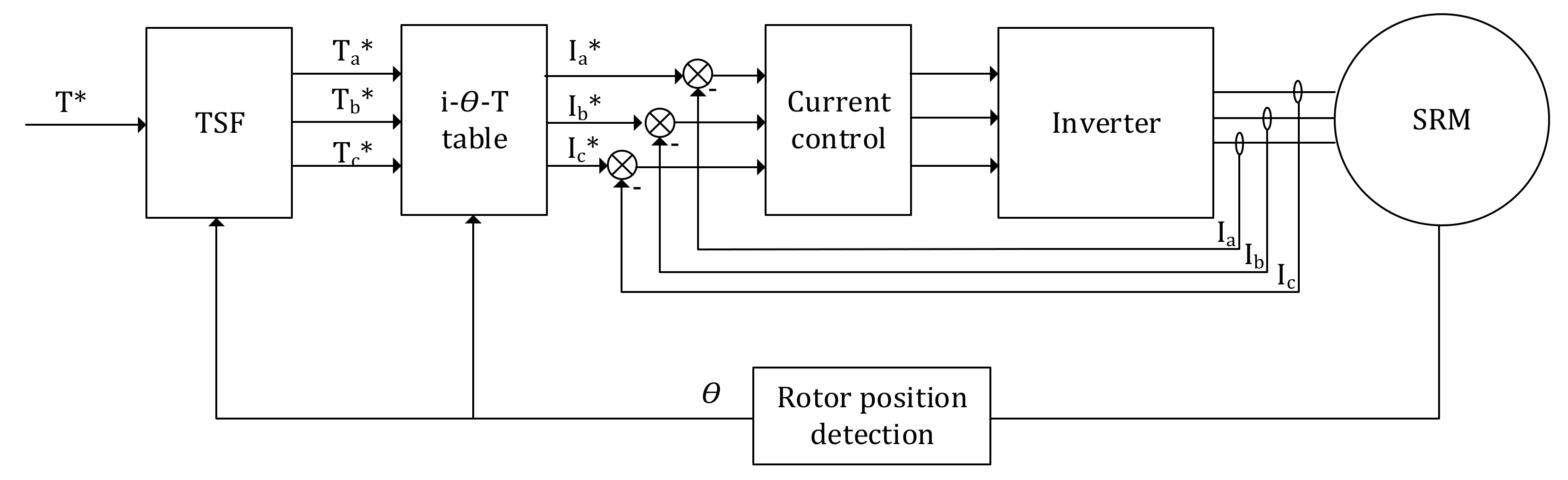
| Torque sharing function (TSF) | Separated reference torque for different phases | It is simple, powerful, popular and efficient. | A high bandwidth current regulator is needed. | [110] |
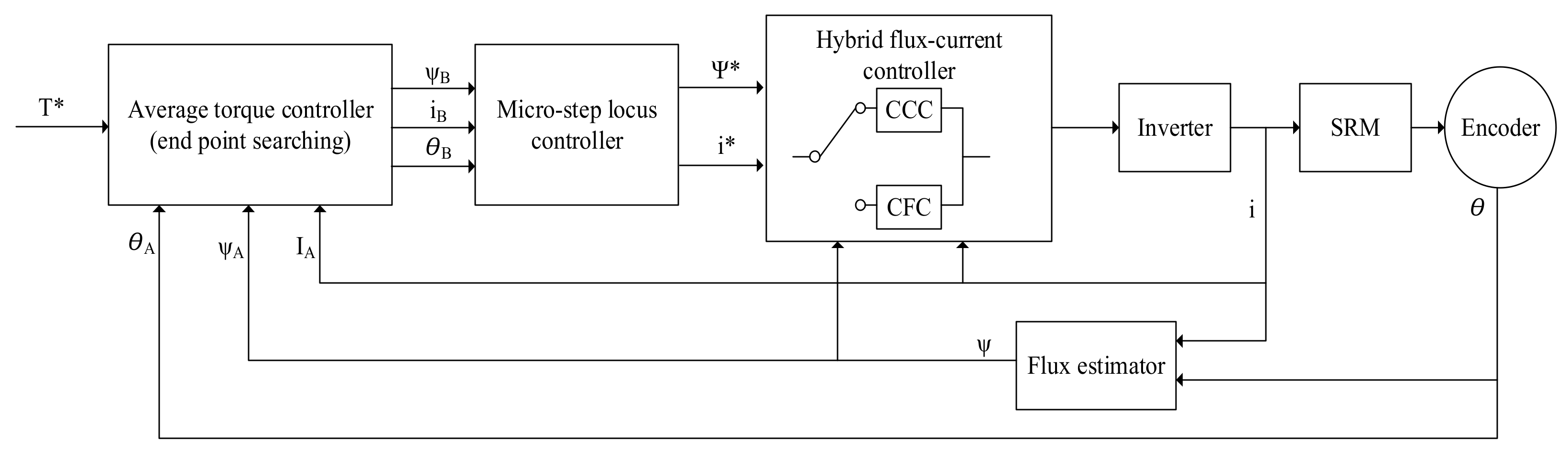
| Average torque control (ATC) | An online average torque estimator | The reference current remains fixed during the excitation. | The torque ripples throughout commutation at the low-speed range. | [105,114,115] |
| Direct instantaneous torque control (DITC) | Instantaneous controlled torque directly | The set of control variables are simple. The decrease of control variables. | The hysteresis switch rule output one phase state. | [111,112] |
| Advanced direct instantaneous torque control (ADITC) | A combination of traditional DITC and the PWM | Control the current variety in single sample time. | Switching frequency is increasing compared to DITC. | [113] |
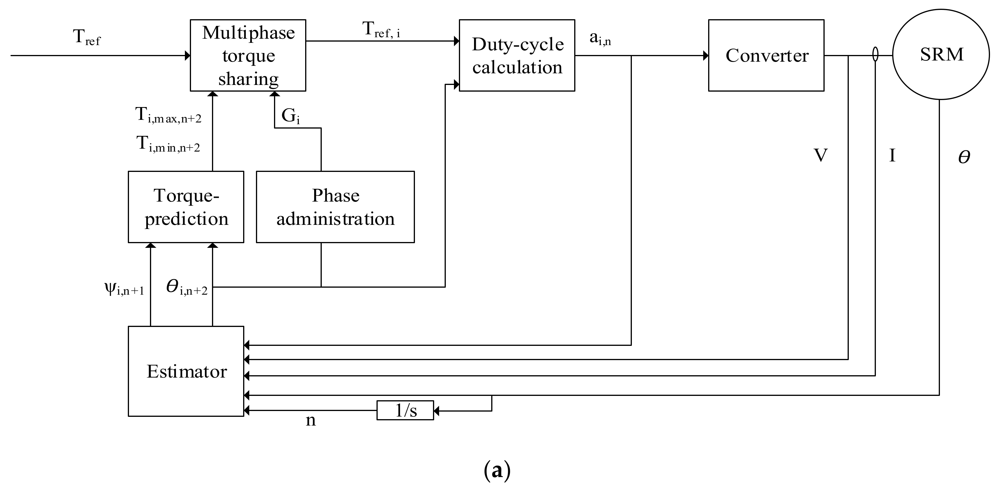
| Predictive PWM direct instantaneous torque control (PWM-DITC) | Predicted upcoming states | It has ability to reduce the required bandwidth of the controller. | The precise information about the machine characteristics is needed to make reasonable efficiency predictions. | [104] |
Publisher’s Note: MDPI stays neutral with regard to jurisdictional claims in published maps and institutional affiliations. |
© 2021 by the authors. Licensee MDPI, Basel, Switzerland. This article is an open access article distributed under the terms and conditions of the Creative Commons Attribution (CC BY) license (https://creativecommons.org/licenses/by/4.0/).
Share and Cite
Lan, Y.; Benomar, Y.; Deepak, K.; Aksoz, A.; Baghdadi, M.E.; Bostanci, E.; Hegazy, O. Switched Reluctance Motors and Drive Systems for Electric Vehicle Powertrains: State of the Art Analysis and Future Trends. Energies 2021, 14, 2079. https://doi.org/10.3390/en14082079
Lan Y, Benomar Y, Deepak K, Aksoz A, Baghdadi ME, Bostanci E, Hegazy O. Switched Reluctance Motors and Drive Systems for Electric Vehicle Powertrains: State of the Art Analysis and Future Trends. Energies. 2021; 14(8):2079. https://doi.org/10.3390/en14082079
Chicago/Turabian StyleLan, Yuanfeng, Yassine Benomar, Kritika Deepak, Ahmet Aksoz, Mohamed El Baghdadi, Emine Bostanci, and Omar Hegazy. 2021. "Switched Reluctance Motors and Drive Systems for Electric Vehicle Powertrains: State of the Art Analysis and Future Trends" Energies 14, no. 8: 2079. https://doi.org/10.3390/en14082079