Article

Optical Performance of Single Point-Focus Fresnel Lens Concentrator System for Multiple Multi-Junction Solar Cells—A Numerical Study

1
School of Mechanical Engineering, University of Birmingham, Edgbaston, Birmingham B15 2TT, UK
2
Mechanical Engineering Department, Jubail University College, Royal Commission for Jubail & Yanbu, Jubail Industrial City 31961, Saudi Arabia
3
Advanced Technology Development Centre, Indian Institute of Technology, Kharagpur 721302, India
*
Authors to whom correspondence should be addressed.
Energies 2021, 14(14), 4301; https://doi.org/10.3390/en14144301
Submission received: 28 May 2021 / Revised: 2 July 2021 / Accepted: 6 July 2021 / Published: 16 July 2021

Abstract

:
This paper investigates the potential of a new integrated solar concentrated photovoltaic (CPV) system that uses a solo point focus Fresnel lens for multiple multi-junction solar cells (MJSCs). The proposed system comprises of an FL concentrator as the primary optical element, a multi-leg homogeniser as the secondary optical element (SOE), a plano-concave lens, and four MJSCs. A three-dimensional model of this system was developed using the ray tracing method to predict the influence of aperture width, height, and position with respect to MJSCs of different reflective and refractive SOE on the overall optical efficiency of the system and the irradiance uniformity achieved on the MJSCs’ surfaces. The results show that the refractive homogeniser using N-BK7 glass can achieve higher optical efficiency (79%) compared to the reflective homogeniser (57.5%). In addition, the peak to average ratio of illumination at MJSCs for the reflective homogeniser ranges from 1.07 to 1.14, while for the refractive homogeniser, it ranges from 1.06 to 1.34, causing minimum effects on the electrical performance of the MJSCs. The novelty of this paper is the development of a high concentration CPV system that integrates multiple MJSCs with a uniform distribution of rays, unlike the conventional CPV systems that utilise a single concentrator onto a single MJSC. The optical efficiency of the CPV system was also examined using both the types of homogeniser (reflective and refractive).

1. Introduction

With increasing concerns about global warming, there has been a shift in focus towards solar power as a renewable and limitless energy source for replacing conventional fossil fuels. In response to the demand growth for more efficient, yet cost effective, energy systems, numerous studies have focused on the performance improvement of photovoltaic (PV) systems and on finding integrated solutions with various hybrid technologies, such as concentration photovoltaic (CPV) systems [1].
CPV systems increase energy flux-density by focusing solar energy onto a smaller area of the receiving solar cell using cost-efficient concentrating optics. These optics work on the principles of refraction or reflection. In reflection-based systems, highly reflective surfaces such as a parabolic trough [2], a parabolic dish [3], or a compound parabolic concentrator [4] are used to reflect and concentrate the solar rays. In refraction-based systems, the principles of refraction are applied using a Fresnel lens [5]. CPV systems are generally classified on the basis of a geometrical parameter called the concentration ratio (CR) achieved by the geometry and the material of the system. A CPV system is classed as a low concentration (CR < 10), medium concentration (10 < CR < 100), high concentration (100 < CR < 2000), and ultrahigh concentration (CR > 2000) [6]. These systems employ various types of solar cell technologies, such as multi-junction solar cells (MJSCs), depending on the field of use, for both solar thermal and solar PV application [7].
In recent years, the use of MJSCs for terrestrial concentrator applications has garnered attention due to their very high conversion efficiency, enabling a significant reduction in the overall system cost for generating electrical power [8]. The basic structure of MJSCs comprises multilayer III-V compound semiconductor materials that have multiple bandgaps for responding to several light wavelength regions [9]. The first layer has the highest bandgap energy for absorbing the shorter wavelength part of the solar radiation spectrum, whereas the next layers have smaller energy bandgaps and are designed to absorb solar radiation in the longer wavelength portion of the spectrum [10].
The use of MJSCs is more appropriate for CPV systems over single junction because of their higher effectiveness, better response to higher solar concentration, and lower temperature coefficient, which ensures a minimal effect on efficiencies for high temperature ranges [11]. The latest reported efficiency of MJSCs is as high as 46%, with a foreseeable potential to touch the 50% mark by the 2030s [12].
Among all concentrating collectors, the Fresnel lens (FL) concentrators are proving lucrative due to their characteristic light-weightiness, smaller size, effective capability of concentration, and low investment costs [13]. Fresnel lenses can mainly be configured as either point-focused or line-focused with both higher and lower concentration ratios, respectively [14]. A general characteristic of an FL is the production of non-uniform flux distribution [15]. This non-uniformity can considerably impact and reduce the electrical output, degrading the efficiency of the CPV system [16]. Thus, the reliability of a CPV system is dependent on a design that can offer uniformity of the illumination.
One way to overcome non-uniformity of illumination is to add a secondary optical element (SOE) in the focal area of the FL concentrator, which can also improve the level of concentration in addition to the uniformity of the irradiance [17]. The SOEs can be categorised into (a) reflective and (b) refractive optical elements, based on the material properties. Reflective-type SOEs, such as hollow reflective truncated pyramids [18] and reflective cones [19], comprise accurately formed materials with a high reflectivity. This ensures an appropriate concentration of the incoming solar irradiance on the cell surfaces, and hence reduces the sensitivity to errors in solar tracking [20]. Examples of refractive SOEs include ball lenses [21], refractive truncated pyramids (RTP), dielectric cross compound parabolic concentrators (DCCPC), single-lens-optical (SILO) elements, and SILO-pyramid and trumpet [22]. These SOEs are fabricated with dielectric materials which are electrical insulators that can be polarised by applying an electric field. In order to attain higher optical efficiencies and enhanced illumination intensity distribution, the principles of total internal reflection and light refraction are taken into consideration, in addition to the material selection [20].
Until now, a lot of research attention has been given to the conventional configuration design of the concentrator, with a focus on the solar radiation on a single solar cell. However, research using single solar concentrators with a number of MJSCs is very limited. In one study, a Cassegrain arrangement-based CPV system was proposed, based on two reflectors used to focus the irradiance onto four MJSCs [23]. This work investigates the potential of using an FL-based refractive system on multiple MJSCs, with a point-focus type of concentration. The point-focused rays were passed via a concave lens and homogeniser-based SOE that distributed the irradiance on the MJSCs’ surfaces uniformly. In order to examine how the various geometrical parameters affect the system, 3-D optical ray tracing model technology was used. The parameters tested were the (i) width and the (ii) height of the homogeniser inlet aperture, (ii) the position of the concave lens with respect to MJSCs on the concentration levels, and (iv) the irradiance uniformity achieved on the MJSCs’ surfaces.

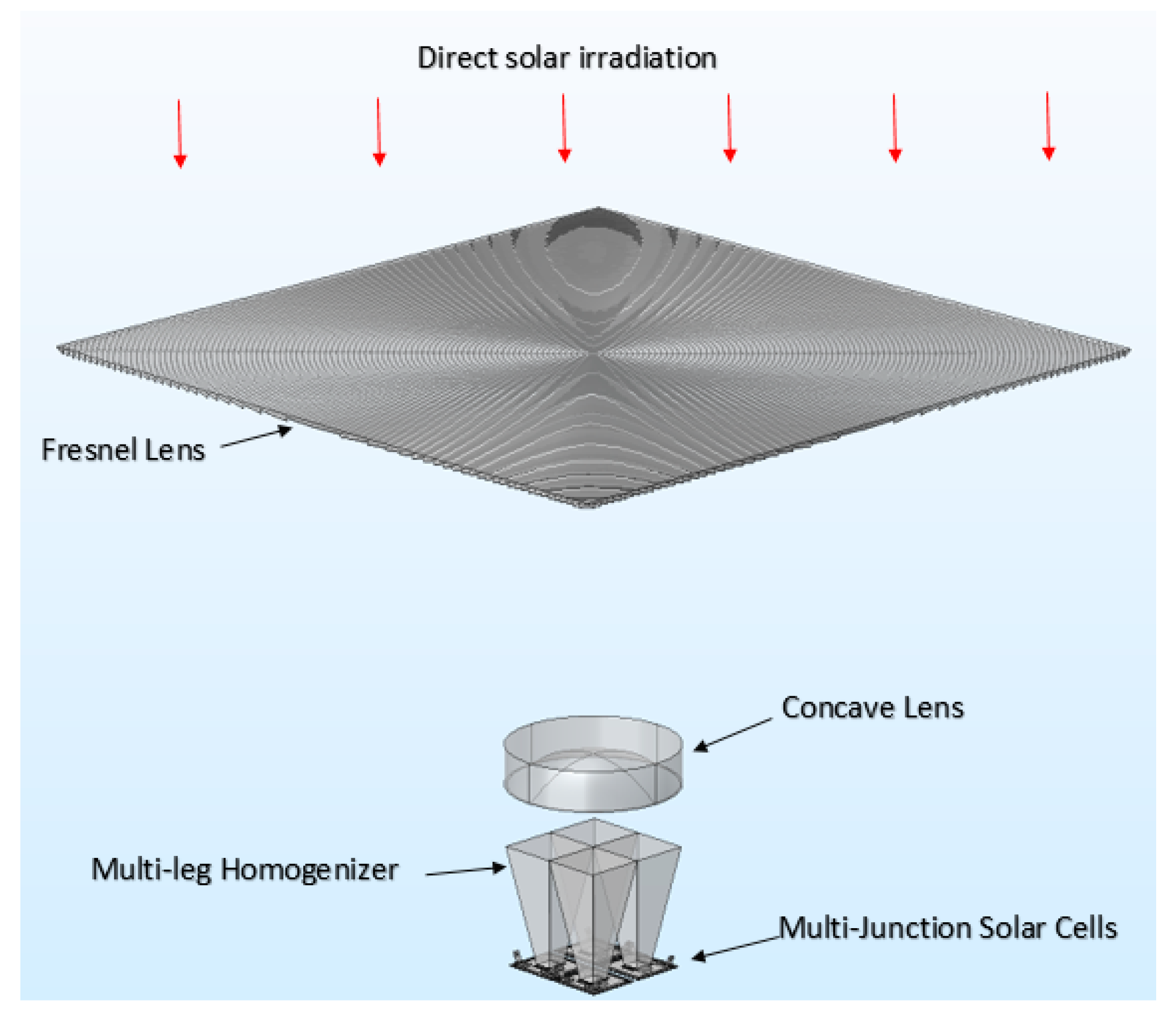
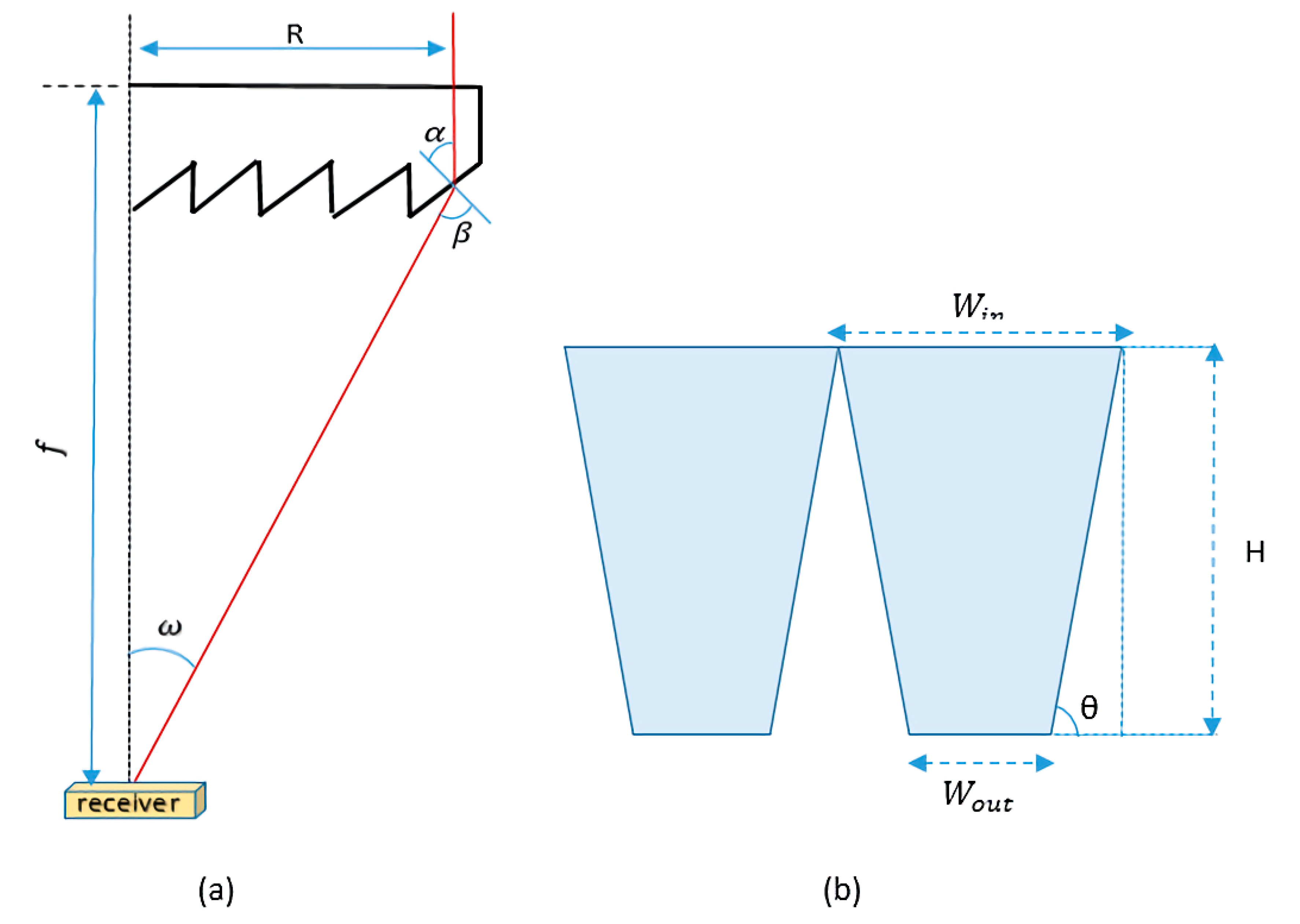
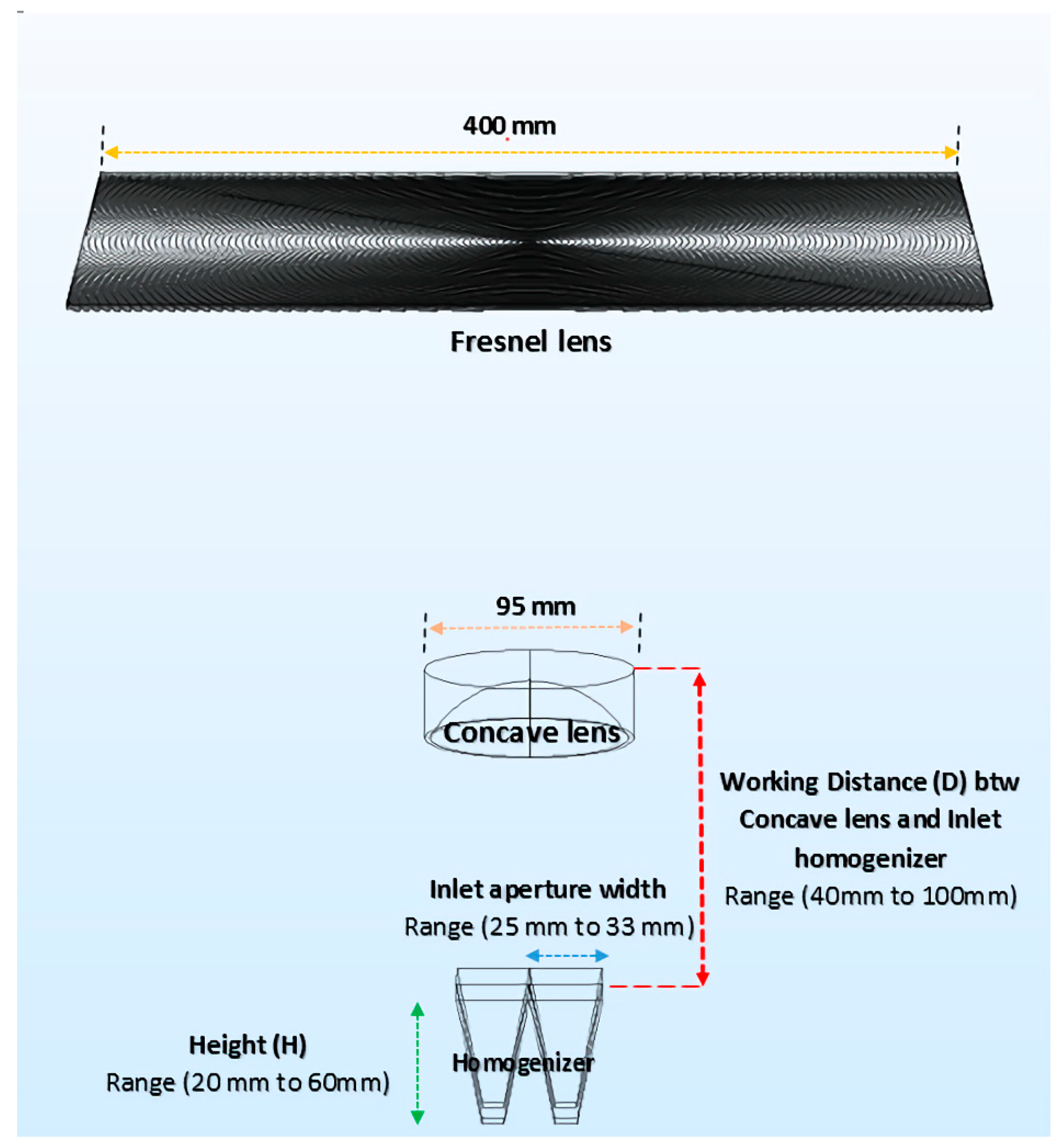
2. Description of the Proposed CPV System

A schematic of the proposed CPV system is given in Figure 1, comprising of a primary optical element (POE) as an FL concentrator, a plano-concave lens (PCL), a secondary optical element (SOE) in the form of a multi-leg homogeniser (MLH), and four MJSCs.
The direct solar irradiance was focused onto the plano-concave lens using the FL concentrator, and a set of Fresnel and plano-concave lenses provided collimated light (i.e., area concentration is achieved instead of point-focus concentration). Then, the four MJSCs were positioned under the MLH in such a way that the solar irradiance was divided into four equal parts for a uniform distribution over the four MJSCs surfaces. For this work, AZURSPACE III-V triple junction solar cells (active area 10 × 10 mm2, material layers composed of GaInP/GaInAs/Ge) were used [25]. Figure 2a shows a point FL concentrator (refractive prisms), used to focus the solar radiation. The MLH design is shown in Figure 2b.
For the individual prisms, the geometric relations can be described by Equations (1)–(4) [26,27]:
n sin α = sin β  
tan ω = R f  
β = α + ω  
tan α = R n R 2 + f 2 f
where all the parameters are defined for the Fresnel lens (FL) concentrator as:
α—prism angle,
R—distance between the incident ray and the optical axis,
n —material refractive index, and
f —focal length.
  A FL (concentrator area) is defined as the product of geometric concentration ratio (GCR), area of MJSC (AMJSC), and the number of MJSCs (NMJSC) as per Equation (5):
AFL = GCR × AMJSC × NMJSC
For the plano-concave lens, the focal length f cl can be determined by Equation (6) [28]:
f cl = D cl 2 × NA  
where D cl represents the plano-concave lens diameter, and NA stands for the numerical aperture of the Fresnel lens.
The MLH design depends on four parameters, namely: (1) the width of inlet aperture ( W in ), (2) the outlet aperture width ( W out ), (3) the slope angle (θ), and (4) the height (H), as shown in Figure 2b. H is determined with the use of Equation (7):
H = W out W in 2   × tan θ  

3. Numerical Simulation Analysis

The most common technique for evaluating the optical performance and optimising various types of solar concentrators is known as ray tracing [29]. As the name suggests, it is the action of “tracing a ray of light through the optical components which allows the modelling of light propagation in different mediums according to the properties applied to the optical components” [30].
For the ray tracing simulation of this proposed CPV system, the gop module of the COMSOL Multiphysics® CFD simulation software was used. This allowed study into 3D, 2D, 2D axisymmetric space dimensions, and bi-directionally coupled time-dependent ray tracing. The aim was to assess the effects of the energy flux distribution and the optical efficiencies on the MJSCs. A total of six first-order differential equations required solving to compute the ray trajectory for K (3D ray vector), q ray (position vector), and ω (angular frequency), as given in the Equations (8) and (9) [31,32]:
dk dt = ω q solar k = x , y , z  
dq solar dt = ω k k = x , y , z  
The Fresnel lens concentrator and the plano-concave lens were, respectively, made of a plastic, polymethyl methacrylate (PMMA), and N-BK7 glass. The ‘N’ type glass offers an environmentally friendly alternative to conventional glass types that contain lead and arsenic. During the ray tracing simulation, both the FL concentrator and the MJSCs were maintained as constant for the proposed CPV system while using different types of materials for MLH. In one case, a reflective material (aluminium; surface reflectivity = 90%) was applied and, in the other case, a refractive material (N-BK7, refractive index n = 1.52) was used.
The CPV system was designed for a CR of 400, with a solar cell size of 10 mm × 10 mm, so the Fresnel lens size can be obtained by using Equation (5) as 400 mm × 400 mm. The focal length of the FL concentrator was designed as 600 mm, with a thickness of 3 mm and an F-number of 1.06. The number of total incident rays generated by the source was 100,000; this number provided a high definition of the intense ray distribution on the outlet aperture. The solar irradiance was 1000 W/m2, with all incident rays considered parallel with the same energy. A ray traced simulation through the optical component is given in Figure 3.

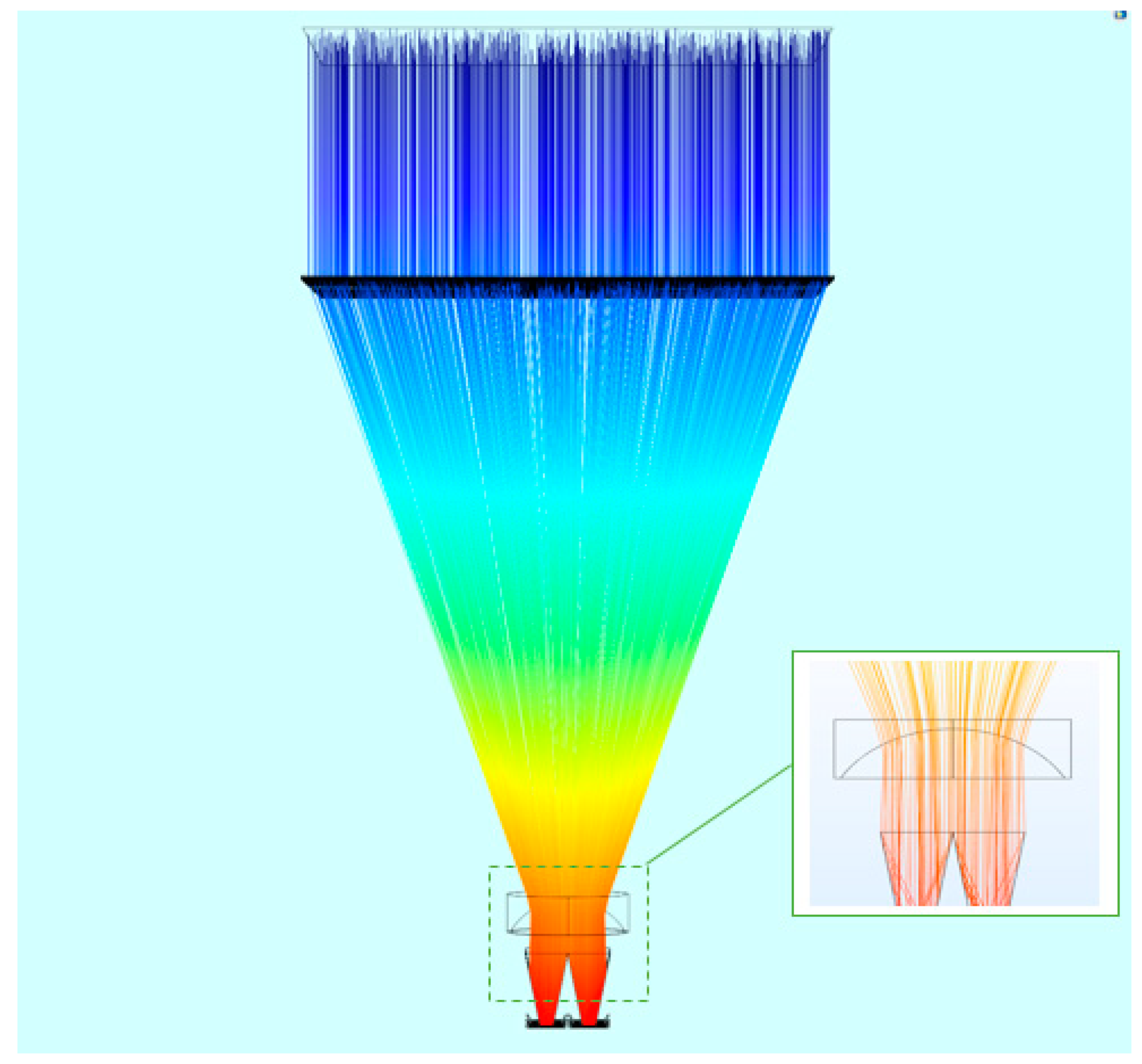
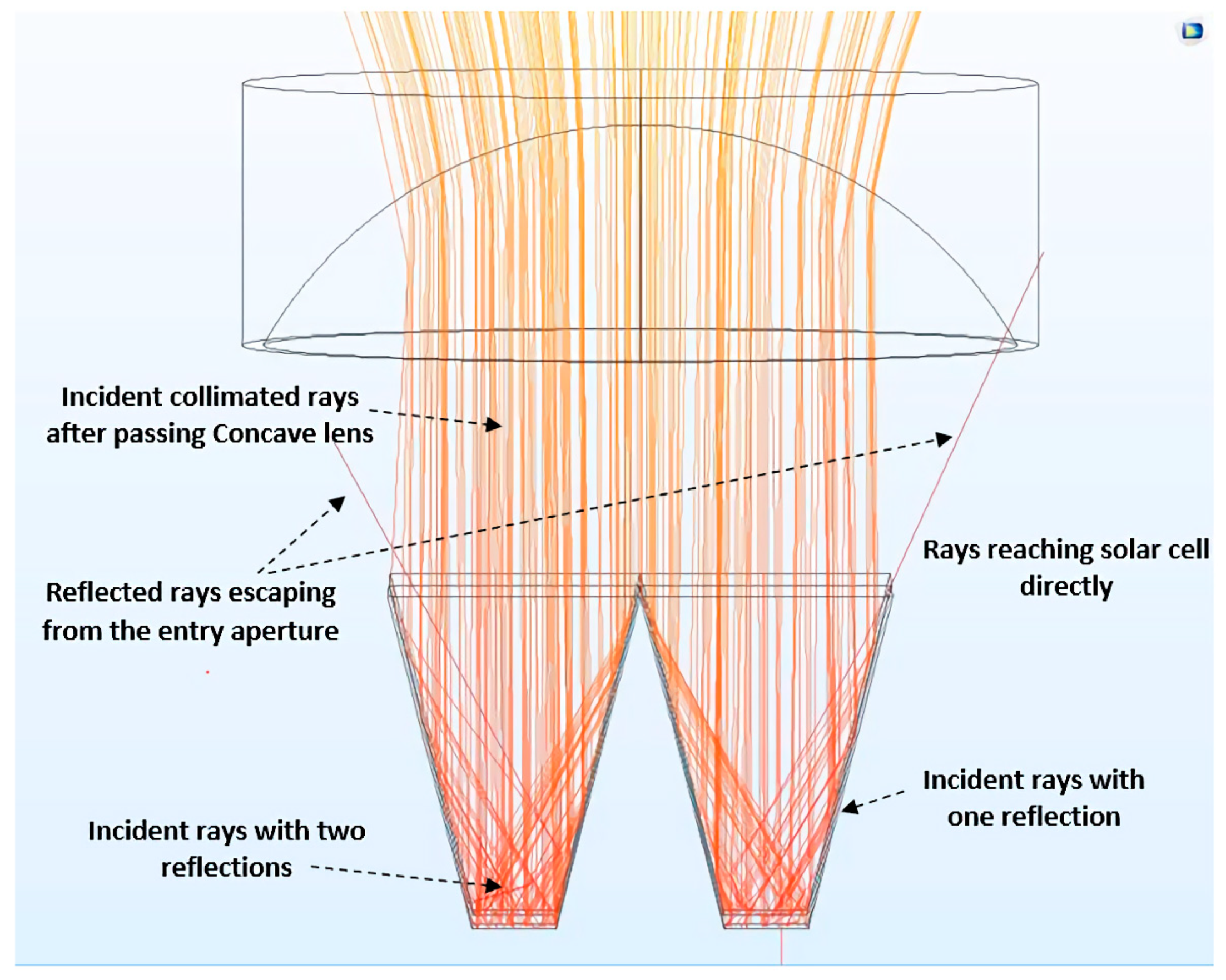
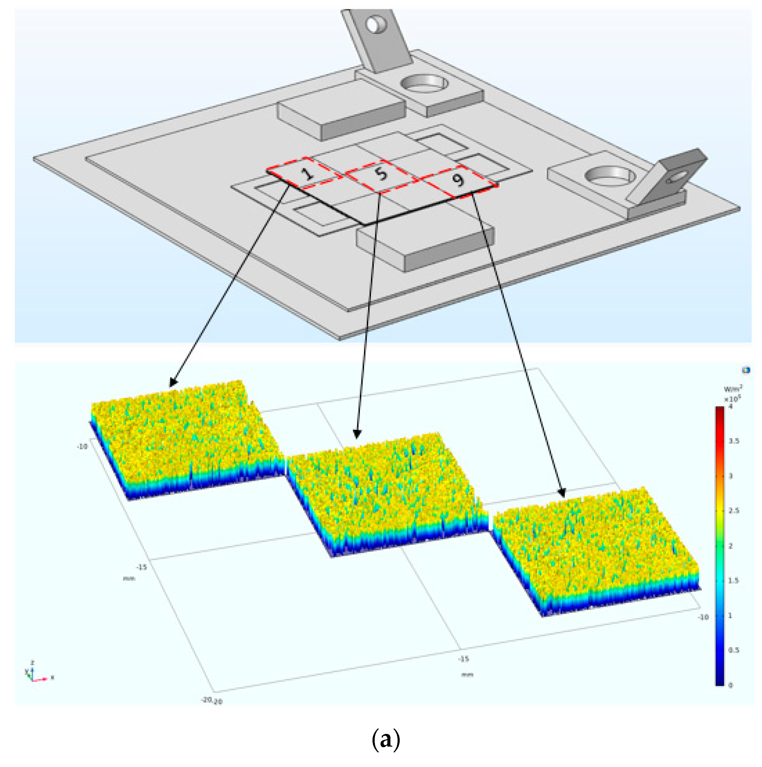
3.1. Ray Tracing through Reflective Homogeniser

Ray tracing simulation was performed on the reflective homogeniser made of aluminium. It was assumed that the inner surfaces of the homogeniser were specular, with a reflectivity of 90%. All the incident rays entering the reflective homogeniser behaved as shown in Figure 4.

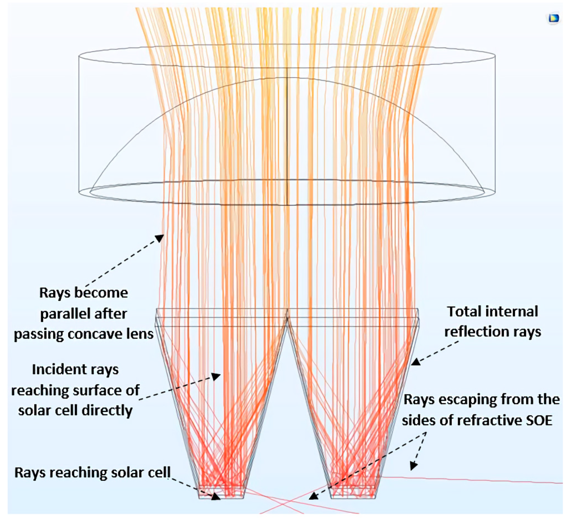
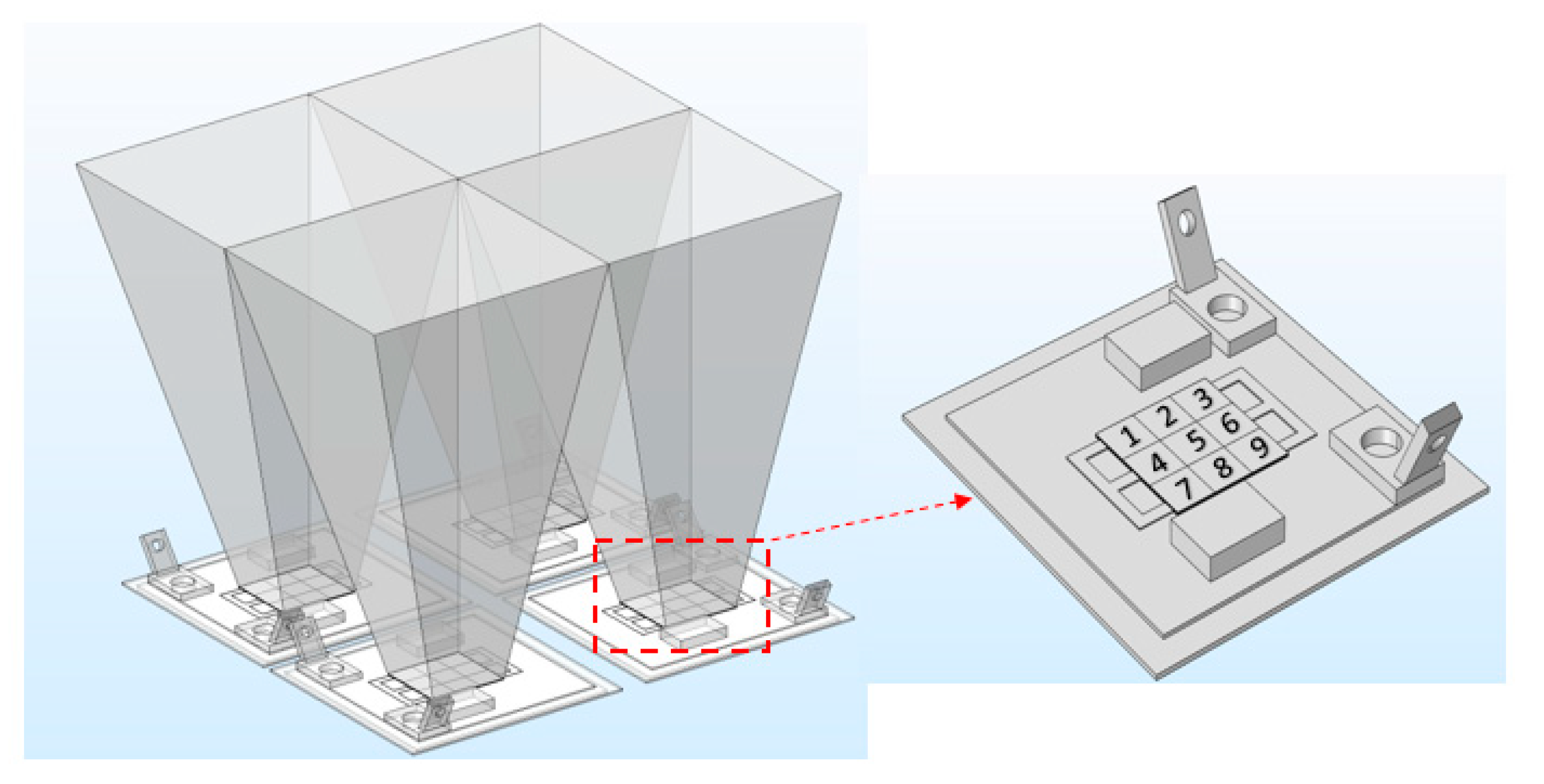
3.2. Ray Tracing through Refractive Homogeniser

The ray tracing simulation was carried out on the refractive homogeniser made from N-BK7, where the light rays moved from the air, with a refractive index of 1, to the N-BK7 material that had an average refractive index of 1.52. Following the law of refraction, all the incident rays entering the refractive homogeniser performed as shown in Figure 5.

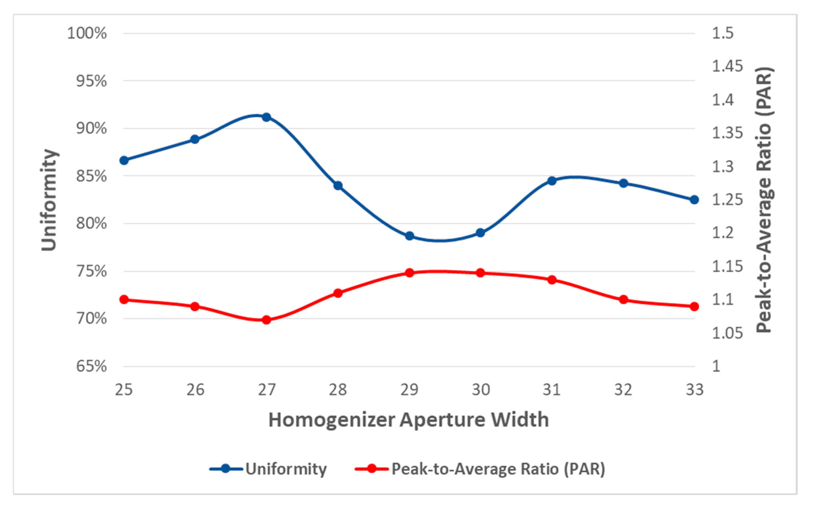
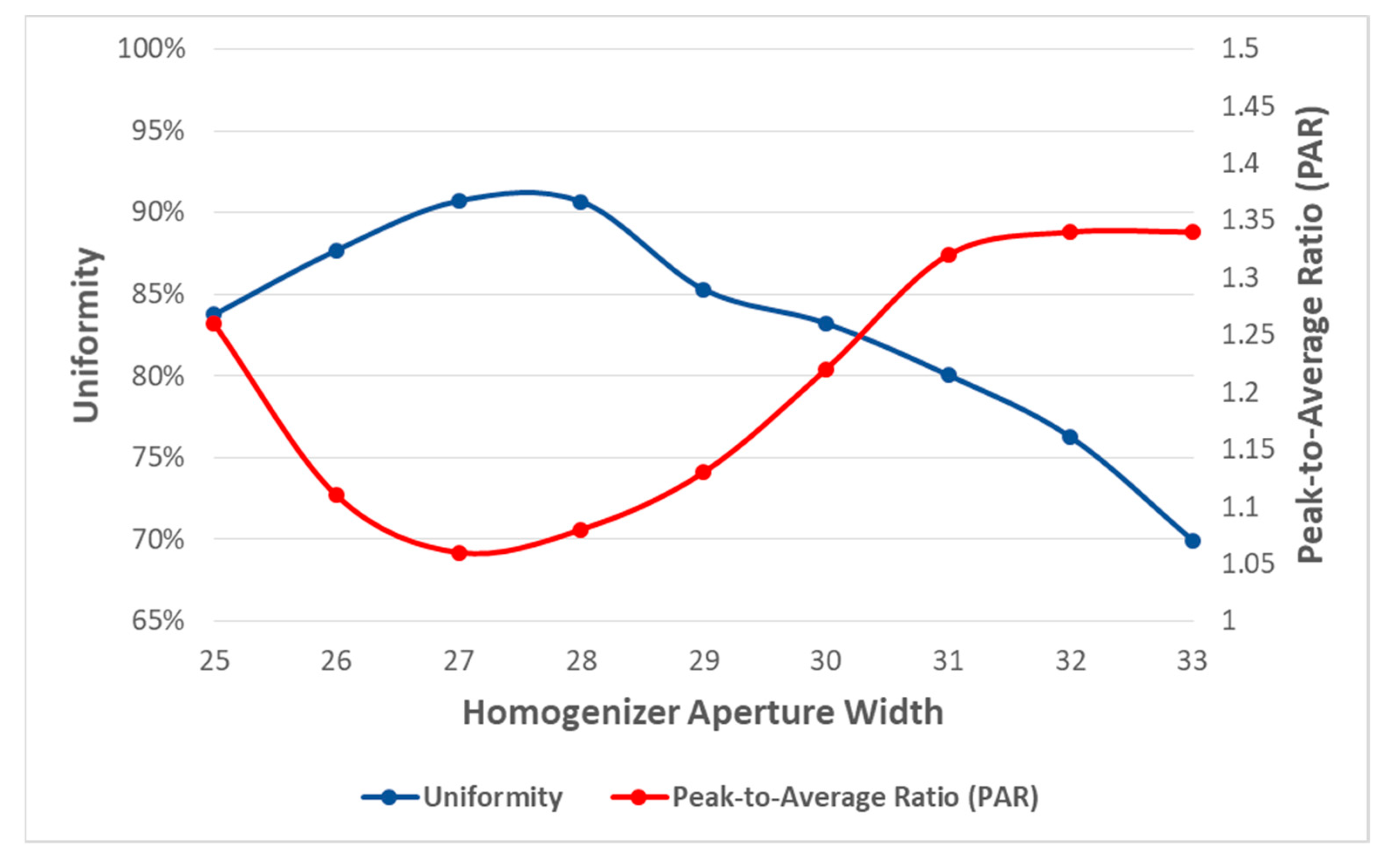
3.3. Irradiation Uniformity on the Solar Cells

The uniformity of the solar radiation on the surfaces of the MJSCs can be evaluated using the American national standard ANSI/NAPMIT7.228-1997 [33]. The average value for intensity ( E a ) can be calculated by using Equation (10), and the definition of uniformity ( N ) by using Equation (11) [34,35].
E a = 1 9 i = 0 8   E i  
N = 1 max E i E a E a × 100 %
The arrangement of the distributed test points was in agreement with ANS, as the MJSC surface was divided into nine equal and comparable rectangular areas (Figure 6).

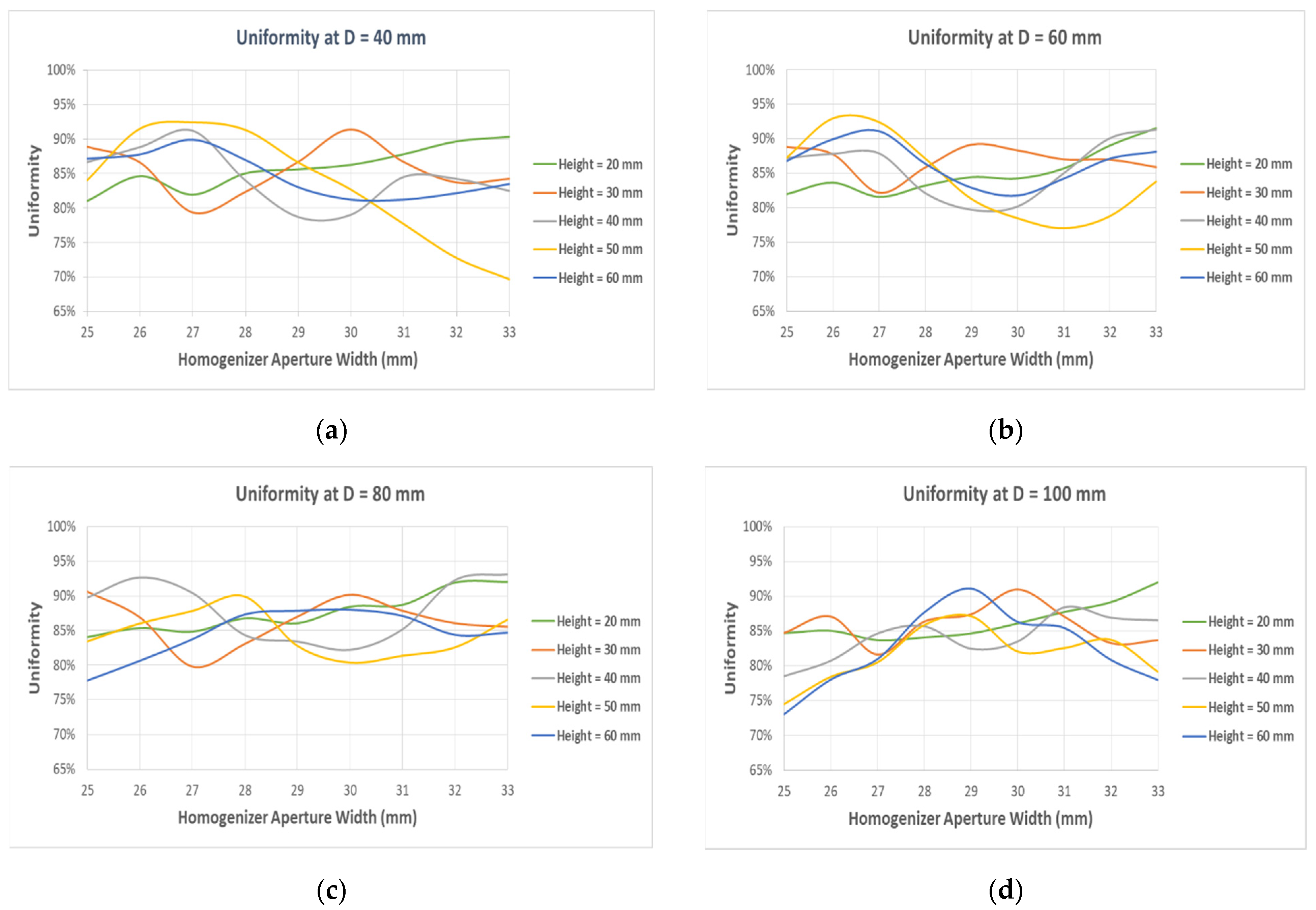
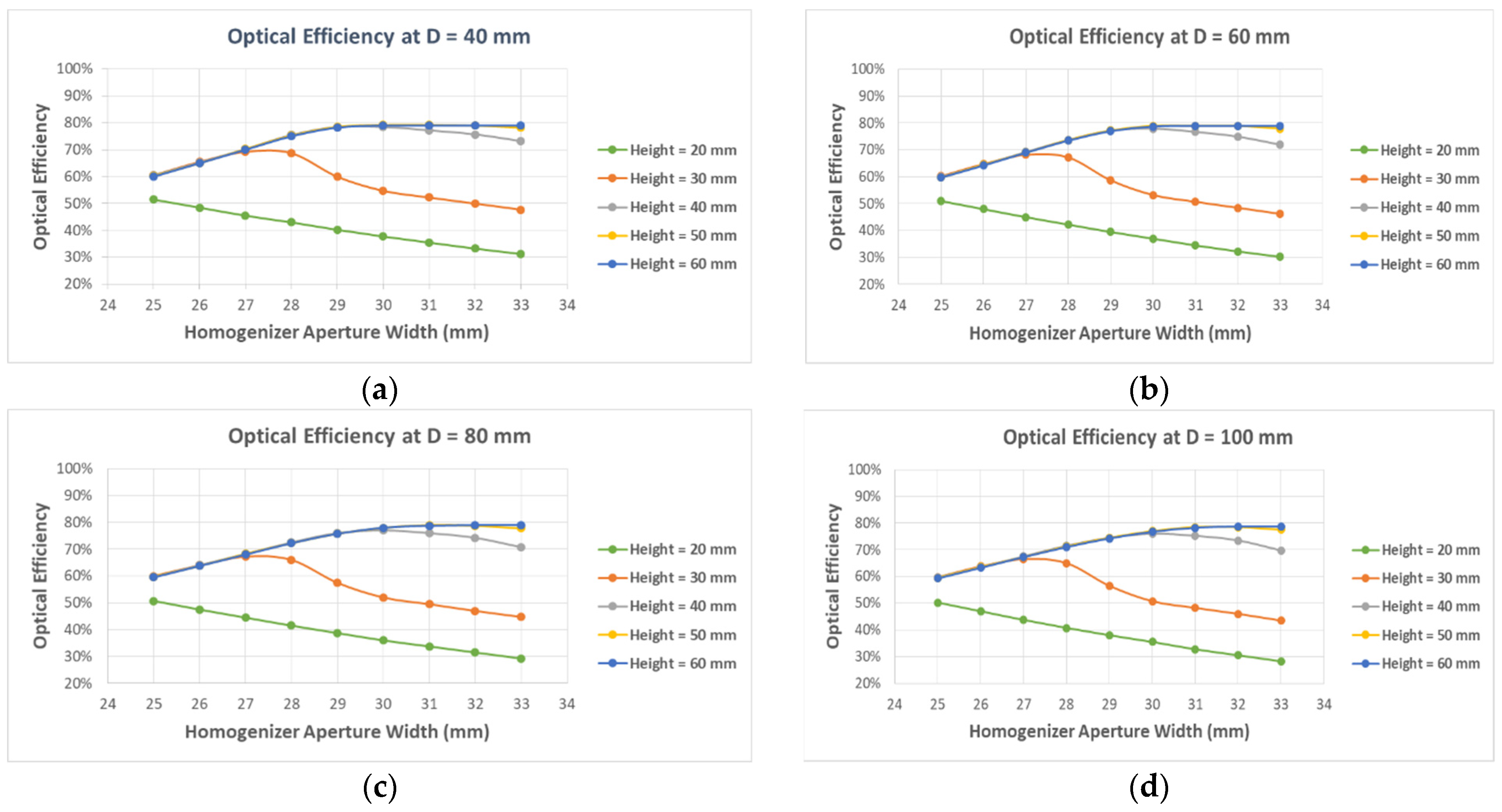
4. Optical Characteristics of the CPV System Using a Reflective Homogeniser

The performance of the CPV was evaluated using the reflective homogeniser with a reflectivity of 90% on the internal surfaces. Figure 7 shows the overall layout of the proposed CPV system with some nominal dimensions. For evaluating the impacts of the key dimensional factors, such as the working distance (D) between the concave lens and homogeniser inlet aperture, and the SOE geometry, a parametric study was carried out. The objective was to reach a higher concentration efficiency and homogeneity in the available irradiance.
The variation in the system optical efficiency at various reflective homogeniser aperture widths and heights is shown in Figure 8, where the inlet homogeniser was placed at different working distances. Four increasing values of the working distance, i.e., 40 mm (where the reflective homogeniser was shifted towards the concave lens), 60 mm, 80 mm, and 100 mm (where the inlet homogeniser was positioned at the system focal point) were examined. This study was conducted for homogenisers of different heights to examine if working distances, except the optimum, can impact the optical efficiency considerably. With variation in the working distances, the effect of shifting the position of the reflective homogeniser with respect to the concave lens is given in Figure 8a–d. It is clear from these figures that the configuration design of the reflective homogeniser (D = 40 mm, aperture width = 29 mm and height = 40 mm) has the highest optical efficiency (reaching about 57.5%) when the irradiance uniformity is 78.7%.
Figure 9 shows the respective variation of the irradiance uniformity on MJSCs for the conditions as presented in Figure 8.

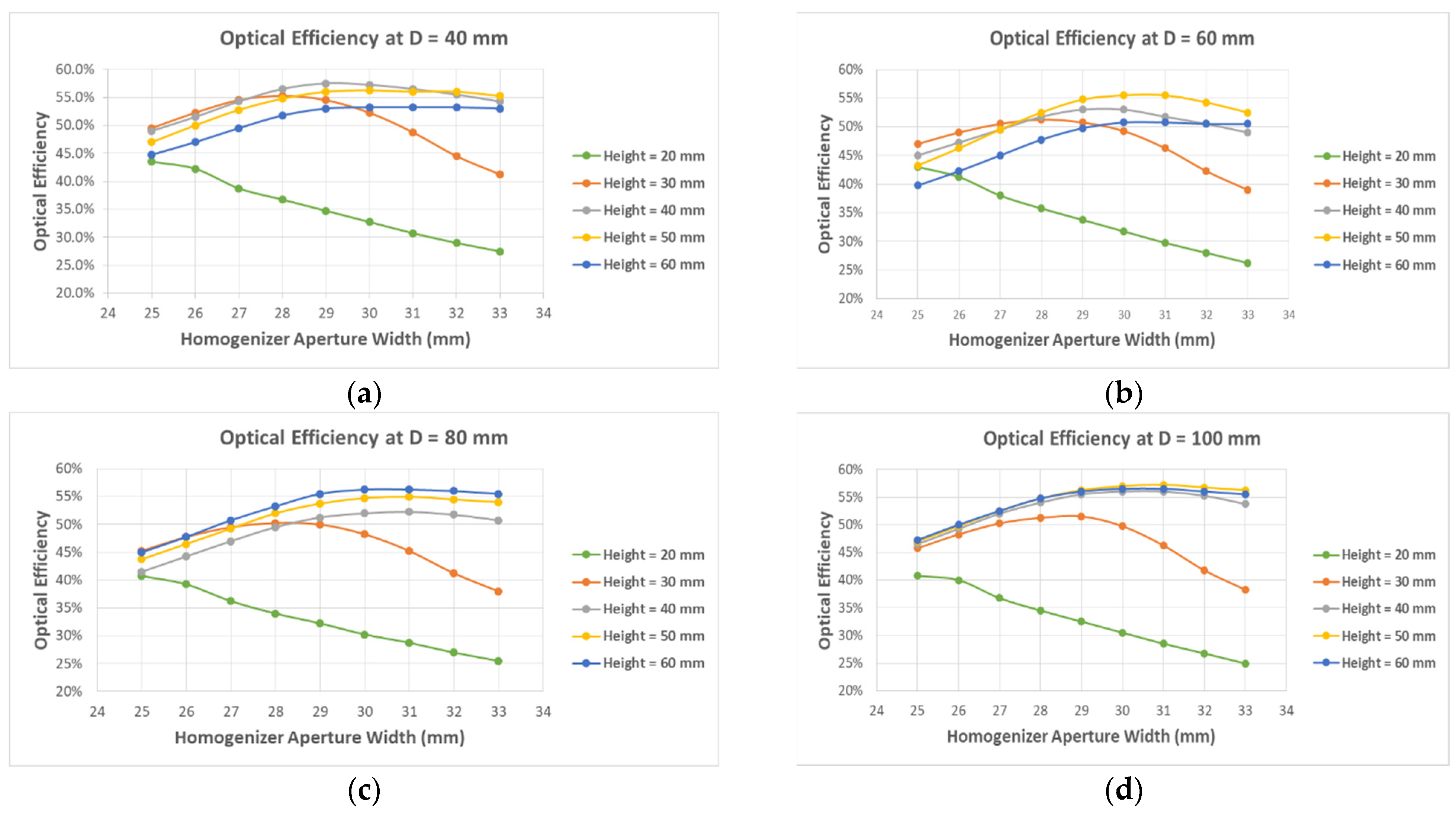
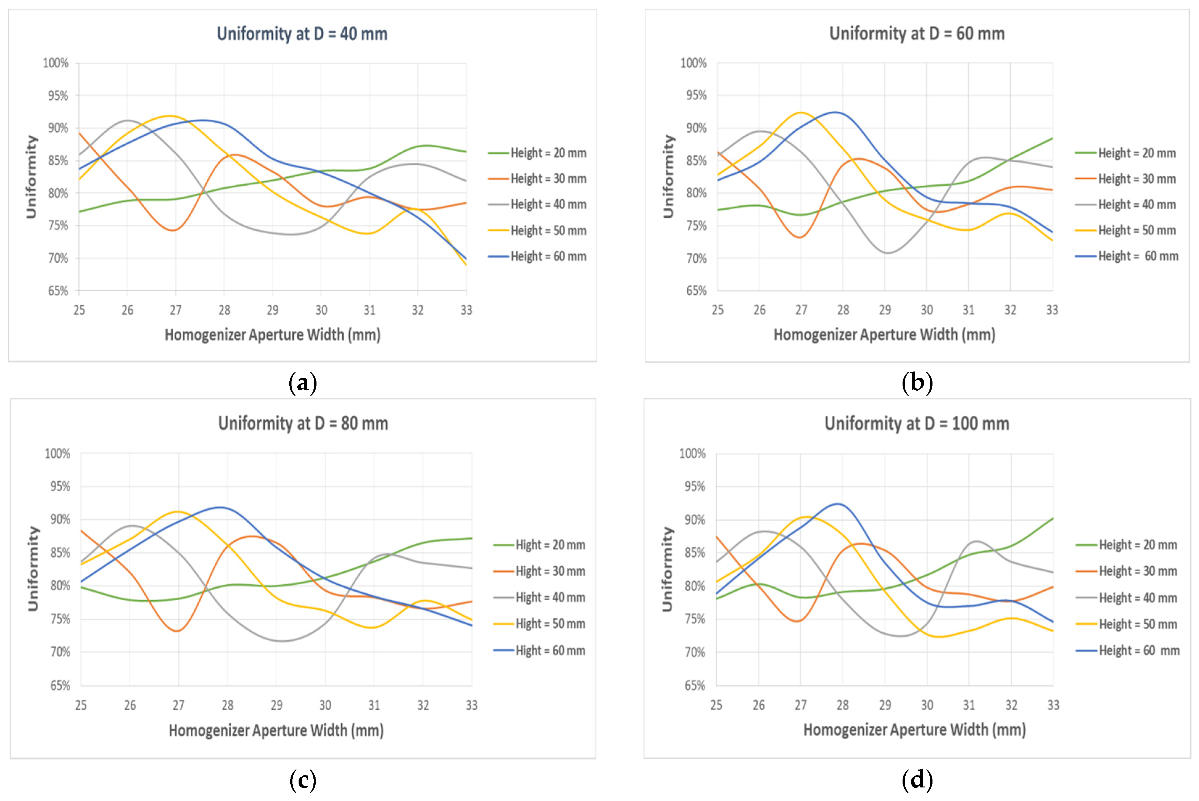
5. Optical Characteristics of the CPV System Using a Refractive Homogeniser

The variation of the system optical efficiency at various refractive homogeniser aperture widths and heights where the inlet homogeniser was placed at different working distances is shown in Figure 10. As can be observed, an increase in the homogeniser height led to an increase in the optical efficiency. Again, it can be seen from Figure 10 that when a 20 mm-high refractive homogeniser was used, the system optical efficiency decreased as the aperture width was increased. It was noticed that with a 30 mm-high refractive homogeniser, the system optical efficiency increased until it reached the 27 mm aperture width and afterwards, the curve started to plunge. The figures make it evident that the configuration design of refractive homogeniser (D = 40 mm, aperture width = 30 mm and height = 60 mm) had the highest optical efficiency, reaching about 79% when the irradiance uniformity was 83.23%.
Figure 11 depicts the influence of change in the irradiance uniformity on the solar cells for the conditions shown in Figure 10. The simulated results reveal that the uniformity distribution on solar cells was in the range of 69.0% to 92.2%. The best uniformity distribution (i.e., above 90%) was obtained with a height of 50 and 60 mm, at an aperture width of 27 and 28 mm for the reflective homogeniser at all working distances (D). In addition, it was demonstrated that for different working distances, the irradiance uniformity showed a similar trend for different heights.

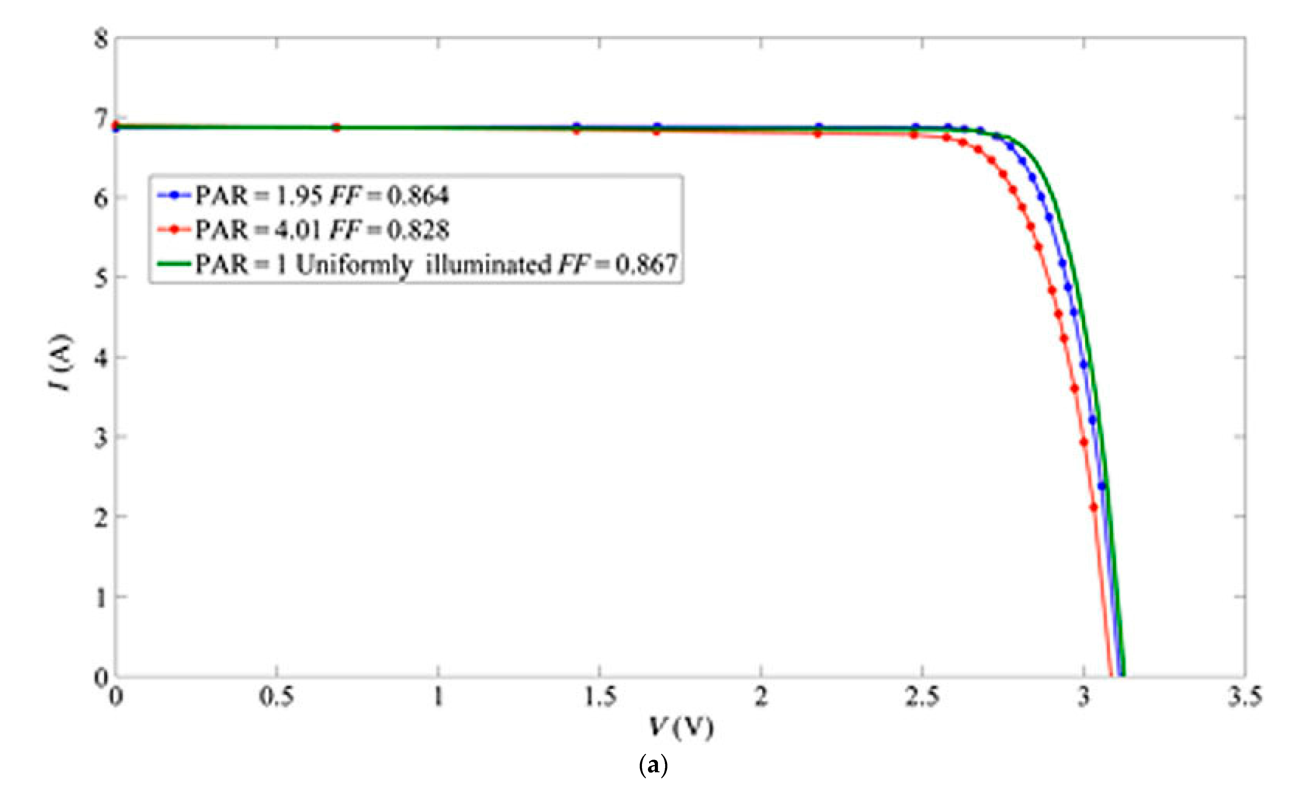
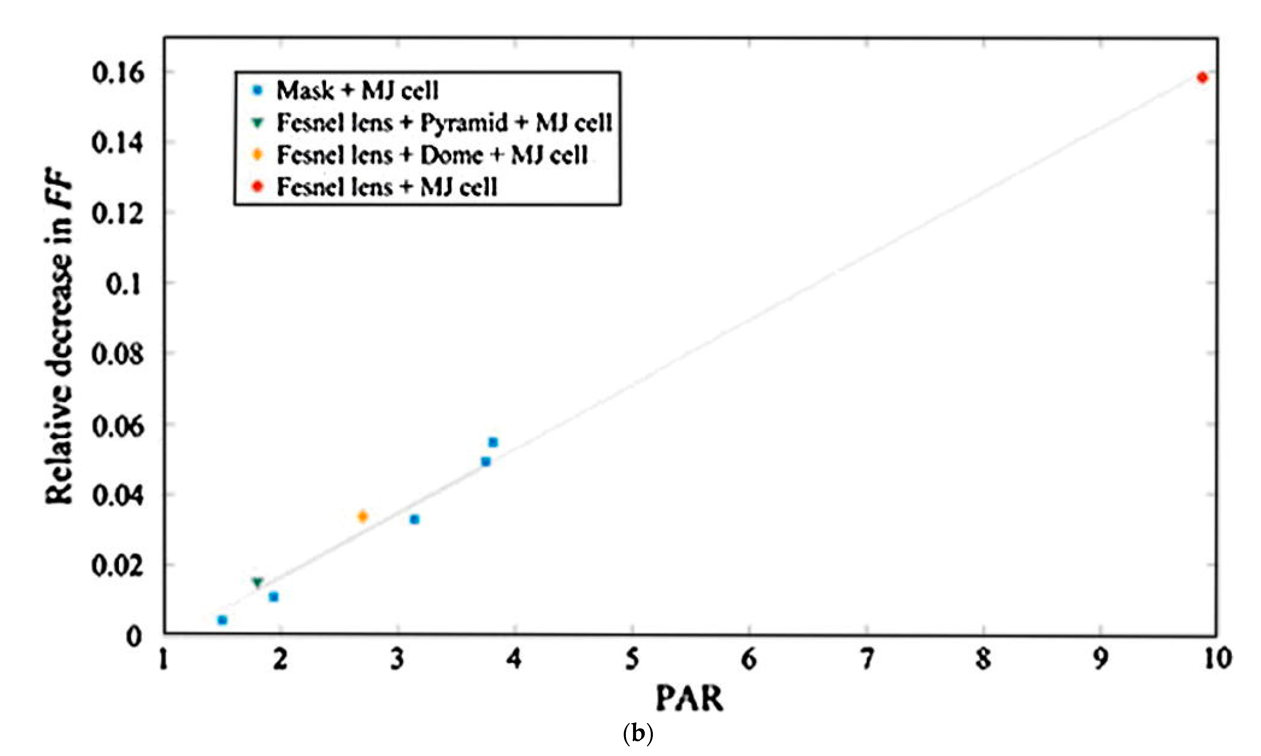
6. Peak to Average Ratio (PAR)

The performance of MJSC under non-uniform illumination distribution saw a reduction in efficiency and fill factor (FF) in comparison to a uniformly illuminated solar cell (Figure 12) [36]. For the quantification of different non-uniform illumination patterns, Herrero et al. [37] introduced the peak-to-average ratio (PAR) parameter. PAR is the ratio of the peak to the average irradiance on the solar cell. This parameter is commonly used for the experimental characterisation and evaluation of the effect of illumination distribution on MJSCs [38,39]. By quantifying the PAR parameter, the relative losses in electrical efficiency and FF due to non-uniform illumination patterns can be evaluated. Figure 12 shows that there were no significant effects of non-uniformity or on the electrical performance of MJSCs when the PAR values were below 2 on the FF [40]. In this study, for the reflective homogeniser, the PAR values of illumination on MJSCs for the configuration design with the highest optical efficiency ranged from 1.07 to 1.14. For the refractive homogeniser, the PAR values ranged from 1.06 to 1.34, as shown in Figure 13 and Figure 14, respectively. Therefore, the system configuration with maximum optical efficiency (79%) can be used since its PAR value was less than 2.
The radiance intensity distribution on the surfaces of the solar cells for the optimum design is given in Figure 15 for the reflective homogeniser, and in Figure 16 for the refractive homogeniser.

7. Conclusions

In contrast to the conventional configuration designs for point-focus Fresnel lens-based concentrators that concentrate solar radiations onto a single MJSC, a new integrated solar concentrated photovoltaic system that uses a single point focus Fresnel lens for multiple MJSCs has been developed. COMSOL Multiphysics® CFD simulation software was used for ray tracing simulation to study the effect of varying the different geometrical parameters on the irradiance uniformity achieved on MJSCs surfaces and the system optical efficiency. The parameters studied were: (a) the inlet aperture width and (b) the height of the homogeniser with (c) the position of the concave lens with respect to the homogeniser inlet aperture. Comparative analysis of the reflective and the refractive secondary optical elements was performed and the optimum configuration design was determined. The results show that the refractive homogeniser made with N-BK7 type glass can achieve a higher optical efficiency (79%) compared to the reflective homogeniser (57.5%). Higher irradiance uniformity of around 83.23% was attained with the refractive homogeniser, compared to 78.70% for the reflective homogeniser. Published work shows that for PAR values below 2, non-uniformity does not considerably affect the fill factor or the electrical performance of MJSCs. In this study, the PAR values of illumination at MJSCs for the configuration design with the highest optical efficiency for reflective homogeniser ranged from 1.07 to 1.14, while for the refractive homogeniser, the PAR values ranged from 1.06 to 1.34. Therefore, the system configuration with the maximum optical efficiency of 79% can be used, since its PAR value is less than 2.

Author Contributions

Conceptualization, Y.A.A., S.M. and R.A.-D.; methodology, Y.A.A. and S.M.; software, Y.A.A.; validation, Y.A.A. and S.M.; formal analysis, Y.A.A. and S.S.; investigation, Y.A.A., S.M., R.A.-D. and S.S.; resources, R.A.-D., Y.D. and J.N.R.; writing—original draft preparation, Y.A.A.; writing—review and editing S.S., Y.D. and J.N.R.; visualization, Y.A.A. and S.S.; supervision, R.A.-D., Y.D. and J.N.R.; project administration, R.A.-D., S.S., S.M. and Y.D.; funding acquisition, R.A.-D., Y.D. and J.N.R. All authors have read and agreed to the published version of the manuscript.

Funding

This research received no external funding.

Institutional Review Board Statement

Not applicable.

Informed Consent Statement

Not applicable.

Data Availability Statement

Not applicable.

Acknowledgments

The authors would like to thankfully acknowledge the British Academy (grant no. UWB190157) and the government of Saudi Arabia represented by the Royal Commission for Jubail and Yanbu for the sponsorship support of the PhD project. Support from EPSRC Grant no. EP/P003605/1 is acknowledged.

Conflicts of Interest

The authors declare no conflict of interest.

Nomenclature

Abbreviations
CFDComputational Fluid Dynamics
CPVConcentrated Photovoltaic
CPVTConcentrated Photovoltaic/Thermal
CRConcentration Ratio
DCCPCDielectric-Cross Compound-Parabolic-Concentrator
FFFill factor
MJSCMulti-Junction Solar Cell
MLHMulti-Leg Homogeniser
PARPeak-to-Average Ratio
PMMAPolymethyl Methacrylate
POEPrimary Optical Element
RTPRefractive Truncated Pyramid
SILOSingle-Lens-Optical Element
SOESecondary Optical Element
Symbols
A FL Area of Fresnel lens (mm2)
AMJSCArea of MJSC (mm2)
DWorking distance between concave lens and inlet homogeniser (mm)
f Focal length of the Fresnel lens (mm)
f cl Focal length of the plano-concave lens (mm)
GCRGeometric concentration ratio
HHeight of the homogeniser (mm)
n Refractive index of the material used for Fresnel lens
NANumerical aperture for the Fresnel lens
NMJSCNumber of MJSC
RDistance between the optical axis and the incident ray of the Fresnel lens (mm)
UUniformity (%)
W in Inlet aperture width of the homogeniser (mm)
W out Outlet aperture width of the homogeniser (mm)

References

  1. Renno, C.; Landi, G.; Petito, F.; Neitzert, H.C. Influence of a degraded triple-junction solar cell on the CPV system performances. Energy Convers. Manag. 2018, 160, 326–340. [Google Scholar] [CrossRef]
  2. Yazdanifard, F.; Ebrahimnia-Bajestan, E.; Ameri, M. Performance of a parabolic trough concentrating photovoltaic/thermal system: Effects of flow regime, design parameters, and using nanofluids. Energy Convers. Manag. 2017, 148, 1265–1277. [Google Scholar] [CrossRef]
  3. Daabo, A.M.; Mahmoud, S.; Al-Dadah, R.K. The effect of receiver geometry on the optical performance of a small-scale solar cavity receiver for parabolic dish applications. Energy 2016, 114, 513–525. [Google Scholar] [CrossRef] [Green Version]
  4. Zhang, H.; Chen, H.; Han, Y.; Liu, H.; Li, M. Experimental and simulation studies on a novel compound parabolic concentrator. Renew. Energy 2017, 113, 784–794. [Google Scholar] [CrossRef]
  5. Xie, W.T.; Dai, Y.J.; Wang, R.Z. Numerical and experimental analysis of a point focus solar collector using high concentration imaging PMMA Fresnel lens. Energy Convers. Manag. 2011, 52, 2417–2426. [Google Scholar] [CrossRef]
  6. Shanks, K.; Senthilarasu, S.; Mallick, T.K. Optics for concentrating photovoltaics: Trends, limits and opportunities for materials and design. Renew. Sustain. Energy Rev. 2016, 60, 394–407. [Google Scholar] [CrossRef] [Green Version]
  7. Baig, H.; Heasman, K.C.; Mallick, T.K. Non-uniform illumination in concentrating solar cells. Renew. Sustain. Energy Rev. 2012, 16, 5890–5909. [Google Scholar] [CrossRef]
  8. Philipps, S.P.; Dimroth, F.; Bett, A.W. High-efficiency III-V multijunction solar cells. Pract. Handb. Photovolt. 2012, 417–448. [Google Scholar] [CrossRef]
  9. Hasan, A.; Sarwar, J.; Shah, A.H. Concentrated photovoltaic: A review of thermal aspects, challenges and opportunities. Renew. Sustain. Energy Rev. 2018. [Google Scholar] [CrossRef]
  10. Sharaf, O.Z.; Orhan, M.F. Concentrated photovoltaic thermal (CPVT) solar collector systems: Part I—Fundamentals, design considerations and current technologies. Renew. Sustain. Energy Rev. 2015, 50, 1500–1565. [Google Scholar] [CrossRef]
  11. Aldossary, A.; Mahmoud, S.; Al-Dadah, R. Technical feasibility study of passive and active cooling for concentrator PV in harsh environment. Appl. Therm. Eng. 2016, 100, 490–500. [Google Scholar] [CrossRef]
  12. Gilmore, N.; Timchenko, V.; Menictas, C. Microchannel cooling of concentrator photovoltaics: A review. Renew. Sustain. Energy Rev. 2018, 90, 1041–1059. [Google Scholar] [CrossRef]
  13. Xie, W.T.; Dai, Y.J.; Wang, R.Z.; Sumathy, K. Concentrated solar energy applications using Fresnel lenses: A review. Renew. Sustain Energy Rev. 2011, 15, 2588–2606. [Google Scholar] [CrossRef]
  14. Imtiaz Hussain, M.; Ali, A.; Lee, G.H. Performance and economic analyses of linear and spot Fresnel lens solar collectors used for greenhouse heating in South Korea. Energy 2015, 90, 1522–1531. [Google Scholar] [CrossRef]
  15. Algora, C.; Rey-Stolle, I. Handbook of Concentrator Photovoltaic Technology; John Wiley & Sons, Ltd.: Hoboken, NJ, USA, 2016. [Google Scholar] [CrossRef]
  16. Ancona, M.A.; Bianchi, M.; Diolaiti, E.; Giannuzzi, A.; Marano, B.; Melino, F. A novel solar concentrator system for combined heat and power application in residential sector. Appl. Energy 2017, 185, 1199–1209. [Google Scholar] [CrossRef]
  17. Victoria, M.; Domínguez, C.; Antón, I.; Sala, G. Comparative analysis of different secondary optical elements for aspheric primary lenses. Opt. Express 2009, 17, 6487. [Google Scholar] [CrossRef]
  18. Nayak, A.; Kinsey, G.S.; Liu, M.; Bagienski, W.; Garboushian, V. Comparison of primary optics in amonix CPV arrays. AIP Conf. Proc. 2012, 1477, 77–80. [Google Scholar] [CrossRef] [Green Version]
  19. Jaus, J.; Bett, A.W.; Reinecke, H.; Weber, E.R. Reflective secondary optical elements for Fresnel lens based concentrator modules. Prog. Photovolt. Res. Appl. 2011, 19, 580–590. [Google Scholar] [CrossRef]
  20. Renzi, M.; Cioccolanti, L.; Barazza, G.; Egidi, L.; Comodi, G. Design and experimental test of refractive secondary optics on the electrical performance of a 3-junction cell used in CPV systems. Appl. Energy 2017, 185, 233–243. [Google Scholar] [CrossRef]
  21. Huang, Q.; Xu, L. Ball lens as secondary optical element for CPV system. Sol. Energy 2017, 148, 57–62. [Google Scholar] [CrossRef]
  22. Ferrer-Rodríguez, J.P.; Baig, H.; Fernández, E.F.; Almonacid, F.; Mallick, T.; Pérez-Higueras, P. Optical modeling of four Fresnel-based high-CPV units. Sol. Energy 2017, 155, 805–815. [Google Scholar] [CrossRef] [Green Version]
  23. Burhan, M.; Chua, K.J.E.; Ng, K.C. Simulation and development of a multi-leg homogeniser concentrating assembly for concentrated photovoltaic (CPV) system with electrical rating analysis. Energy Convers. Manag. 2016, 116, 58–71. [Google Scholar] [CrossRef]
  24. Alamri, Y.A.; Albaik, I.; Mahmoud, S.; Al-Dadah, R.; Ismail, M.A. Integration of concentrated multi-junction solar cells with small-scale organic rankine cycle. Energy Convers. Manag. 2021, 239, 114235. [Google Scholar] [CrossRef]
  25. Azure Space Solar Power GMBH. Enhanced Fresnel Assembly—EFA Type: 3C42A—with 10 × 10 mm2 CPV TJ Solar Cell Application: Concentrating Photovoltaic (CPV) Modules; Azure Space Solar Power GMBH: Heilbronn, Germany, 2014; p. 4. Available online: http://azurspace.com/images/products/DB_3987-00-00_3C42_AzurDesign_EFA_10x10_2014-03-27.pdf (accessed on 20 April 2020).
  26. Leutz, R.; Suzuki, A. Nonimaging Fresnel Lenses: Design and Performance of Solarconcentrators; Springer: Heidelberg, Germany, 2001. [Google Scholar]
  27. Zhuang, Z.; Yu, F. Optimization design of hybrid Fresnel-based concentrator for generating uniformity irradiance with the broad solar spectrum. Opt. Laser Technol. 2014, 60, 27–33. [Google Scholar] [CrossRef]
  28. Malacara, D. Optical Shop Testing: Third Edition; John Wiley & Sons, Inc.: Hoboken, NJ, USA, 2006. [Google Scholar] [CrossRef]
  29. Al-Shohani, W.A.M.; Al-Dadah, R.; Mahmoud, S.; Algareu, A. Optimum design of V-trough concentrator for photovoltaic applications. Sol. Energy 2016, 140, 241–254. [Google Scholar] [CrossRef]
  30. Yılmaz, İ.H.; Mwesigye, A. Modeling, simulation and performance analysis of parabolic trough solar collectors: A comprehensive review. Appl. Energy 2018, 225, 135–174. [Google Scholar] [CrossRef]
  31. Born, M.A.X. Principles of optics. Spectrosc. Ellipsom. 1959, 13–48. [Google Scholar] [CrossRef]
  32. Hassanzadeh, A.; Jiang, L.; Winston, R. Coupled optical-thermal modeling, design and experimental testing of a novel medium-temperature solar thermal collector with pentagon absorber. Sol. Energy 2018, 173, 1248–1261. [Google Scholar] [CrossRef]
  33. American National Standard Institute, Inc., ANSI/NAPMIT7.228-1997. Electronic Projection-Fixed Resolution Projectors; National Association of Photographic Manufacture, Inc.: New York, NY, USA, 1997. [Google Scholar]
  34. Gong, J.; Wang, C.; Gong, C.; Liang, F.; Ma, J. Study on the uniformity of high concentration photovoltaic system with array algorithm. Sol. Energy 2017, 153, 181–187. [Google Scholar] [CrossRef]
  35. Wang, C.L.; Gong, J.H.; Yan, J.J.; Zhou, Y.; Fan, D.W. Theoretical and experimental study on the uniformity of reflective high concentration photovoltaic system with light funnel. Renew. Energy 2019, 133, 893–900. [Google Scholar] [CrossRef]
  36. Herrero, R.; Victoria, M.; Domínguez, C.; Askins, S.; Antón, I.; Sala, G. Concentration photovoltaic optical system irradiance distribution measurements and its effect on multi-junction solar cells. Prog. Photovolt. Res. 2012, 20, 423–430. [Google Scholar] [CrossRef] [Green Version]
  37. Herrero, R.; Victoria, M.; Askins, S.; Domínguez, C.; Antón, I.; Sala, G.; Berrios, J. Indoor characterization of multi-junction solar cells under non uniform light patterns. AIP Conf. Proc. 2010, 1277, 36–38. [Google Scholar] [CrossRef]
  38. Victoria, M.; Herrero, R.; Domínguez, C.; Antón, I.; Askins, S.; Sala, G. Characterization of the spatial distribution of irradiance and spectrum in concentrating photovoltaic systems and their effect on multi-junction solar cells. Prog. Photovolt. Res. 2013, 21, 308–318. [Google Scholar] [CrossRef] [Green Version]
  39. Saura, J.M.; Fernández, E.F.; Almonacid, F.M. Characterisation and impact of non- uniformity on multi-junction solar cells (MJSC) caused by concentrator optics. AIP Conf. Proc. 2019, 2149. [Google Scholar] [CrossRef]
  40. Herrero, R.; Victoria, M.; Domínguez, C.; Askins, S.; Antón, I.; Sala, G. Understanding causes and effects of non-uniform light distributions on multi-junction solar cells: Procedures for estimating efficiency losses. AIP Conf. Proc. 2015, 1679. [Google Scholar] [CrossRef] [Green Version]
Figure 1. A schematic for the proposed FL-MJSCs-based CPV system under investigation [24].
Energies 14 04301 g001
Figure 2. Design and geometry of the (a) point FL concentrator, and (b) MLH [24].
Energies 14 04301 g002
Figure 3. Ray tracing path through optical components.
Energies 14 04301 g003
Figure 4. Path of concentrated incident rays through the reflective homogeniser.
Energies 14 04301 g004
Figure 5. Path of the concentrated incident rays through the refractive homogeniser.
Energies 14 04301 g005
Figure 6. The uniformity assessment through discretization of the solar cell area [24].
Energies 14 04301 g006
Figure 7. Layout of the proposed CPV system.
Energies 14 04301 g007
Figure 8. The variation of the system optical efficiency using a reflective homogeniser when the inlet homogeniser was placed at working distances, D of: (a) 40 mm, (b) 60 mm, (c) 80 mm, and (d) 100 mm, and aperture widths and heights.
Energies 14 04301 g008
Figure 9. Uniformity distribution on the solar cell using a reflective homogeniser at various homogeniser aperture widths, homogeniser heights, and working distances, D of: (a) 40 mm, (b) 60 mm, (c) 80 mm, and (d) 100 mm.
Energies 14 04301 g009
Figure 10. The variation in optical efficiency using a refractive homogeniser when the inlet homogeniser was placed at working distances, D of: (a) 40 mm, (b) 60 mm, (c) 80 mm, and (d) 100 mm, and aperture widths and heights.
Energies 14 04301 g010
Figure 11. Uniformity distribution on solar cell using a refractive homogeniser at various homogeniser aperture widths, homogeniser heights, and working distances, D of: (a) 40 mm, (b) 60 mm, (c) 80 mm, and (d) 100 mm.
Energies 14 04301 g011
Figure 12. (a) I–V characteristics for uniform vs. non-uniform illumination, and (b) variation in FF vs. PAR (% values) for an MJSC [36].
Energies 14 04301 g012aEnergies 14 04301 g012b
Figure 13. PAR values for the reflective homogeniser: equivalent to the uniformity for the configuration design with the highest optical efficiency.
Energies 14 04301 g013
Figure 14. PAR values for the refractive homogeniser: equivalent to the uniformity for the configuration design with the highest optical efficiency.
Energies 14 04301 g014
Figure 15. Irradiance intensity distribution on the surfaces of the solar cells: configuration designs of reflective homogeniser (D = 40 mm, aperture width = 29 mm, and height = 40 mm).
Energies 14 04301 g015aEnergies 14 04301 g015b
Figure 16. Irradiance intensity distribution on the surfaces of the solar cells: configuration design of refractive homogeniser (D = 40 mm, aperture width = 30 mm, and height = 60 mm).
Energies 14 04301 g016aEnergies 14 04301 g016b
Publisher’s Note: MDPI stays neutral with regard to jurisdictional claims in published maps and institutional affiliations.

