
Magnetic Refrigeration Design Technologies: State of the Art and General Perspectives
by
 , , ,
, , ,
Ali Alahmer
1 ,
,
Malik Al-Amayreh
2 ,
,
Ahmad O. Mostafa
1 ,
,
Mohammad Al-Dabbas
3 and
Hegazy Rezk
4,5,* 1
Department of Mechanical Engineering, Faculty of Engineering, Tafila Technical University, P.O. Box 179, Tafila 66110, Jordan
2
Department of Alternative Energy Technology, Faculty of Engineering and Technology, Al-Zaytoonah University, P.O. Box 130, Amman 11733, Jordan
3
Mechanical Engineering Department, Mutah University, P.O. Box 7, Mutah, Karak 61710, Jordan
4
College of Engineering at Wadi Addawaser, Prince Sattam Bin Abdulaziz University, Wadi Addawaser 11991, Saudi Arabia
5
Electrical Engineering Department, Faculty of Engineering, Minia University, Minia 61517, Egypt
*
Author to whom correspondence should be addressed.
Energies 2021, 14(15), 4662; https://doi.org/10.3390/en14154662
Submission received: 7 June 2021
/
Revised: 17 July 2021
/
Accepted: 24 July 2021
/
Published: 31 July 2021
(This article belongs to the Special Issue New Horizons for Low-Temperature Engineering: From Refrigeration to Cryogenics)
Abstract
:Magnetic refrigeration is a fascinating superior choice technology as compared with traditional refrigeration that relies on a unique property of particular materials, known as the magnetocaloric effect (MCE). This paper provides a thorough understanding of different magnetic refrigeration technologies using a variety of models to evaluate the coefficient of performance (COP) and specific cooling capacity outputs. Accordingly, magnetic refrigeration models are divided into four categories: rotating, reciprocating, C-shaped magnetic refrigeration, and active magnetic regenerator. The working principles of these models were described, and their outputs were extracted and compared. Furthermore, the influence of the magnetocaloric effect, the magnetization area, and the thermodynamic processes and cycles on the efficiency of magnetic refrigeration was investigated and discussed to achieve a maximum cooling capacity. The classes of magnetocaloric magnetic materials were summarized from previous studies and their potential magnetic characteristics are emphasized. The essential characteristics of magnetic refrigeration systems are highlighted to determine the significant advantages, difficulties, drawbacks, and feasibility analyses of these systems. Moreover, a cost analysis was provided in order to judge the feasibility of these systems for commercial use.
1. Introduction
Some magnetic materials exhibit either an increase or drop in their temperatures when they are exposed to a certain magnetic field. This phenomenon is referred to as the magnetocaloric effect (MCE) or adiabatic temperature change [1]. For such a thermal response, a magnetocaloric material maximizes its temperature when it reaches the magnetic ordering temperature [2]. The magnetocaloric material is strongly limited by the temperature span in which the specific entropy density changes in response to the magnetic field [3]. To achieve a greater temperature span, the MCE should be magnified by handling the magnetic field strength (B), magnetic entropy transition (ΔSm), bulk magnetization, variation of the magnetic field (ΔB), the Curie temperature (TC) of a magnetic material, the magnetic phase transition properties, and crystallographic transformation [4]. In 1881, Warburg [5] discovered the MCE phenomenon in pure iron. Napoletano et al. [6] reported that when a magnetic field reaches up to 9 Tesla, the temperature change occurs in the 3 to 300 K range due to the MCE effect. Debye [7] and Giauque [8] explained the occurrence of the MCE phenomenon and proposed methods using adiabatic demagnetization cooling to reach an ultra-low temperature scale. Recently, MCE-based magnetic refrigeration has been established in the room temperature range. The magnitude of the MCE of the magnetic material is critical for cooling power, whether at room temperature or even lower. The development of this technology basically depends on improved material selection, the magnet type, and optimal design of cooling devices [9].
Magnetic refrigeration technology has many advantages, which can be summarized as follows: (i) Due to the use of magnetic materials as refrigerants, an environmentally friendly refrigeration technology, which produces no ozone-depleting gases or greenhouse gas pollution, is utilized [10]. (ii) Magnetic materials have a higher magnetic entropy density than gas refrigerants [11]. (iii) MCE may be supplied by electromagnets, superconductors, or permanent magnets, which do not need high rotational speeds, mechanical vibrations, noise, low stability, or short life spans to be functionally operated [12]. (iv) The efficiency of magnetic refrigeration systems can be 30–60% of the Carnot cycle [13], unlike 5–10% for conventional refrigeration technologies. Some findings in a 5 T magnetic field area can generate up to 600 W of cooling power and 60% of Carnot efficiency, with a COP of around 15. However, at a maximum temperature range of 38 K, the cooling capacity drops down to about 100 W. In a 1.5 T magnetic field area, MCE systems provide around 200 W of cooling capacity [14]. According to Aprea et al. [15], the COP of the active magnetic regenerative refrigeration (AMRR) cycle is better than traditional refrigeration at low mass flow rates. However, it improves at large mass flow rates with the flat plate regenerator. (v) It has good reliability; due to the absence of cooling gases, the MCE system reduces concerns of releasing emissions into the atmosphere. (vi) It is a maintenance-free technology. According to Gschneidner and Pecharsky [16], a magnetic refrigerator ran for over than 1500 h and 18 months with no significant repairs or breakdowns. (vii) It has a simple machine design, such as a rotary porous heat exchanger refrigerator. (viii) Finally, it can be operated below atmospheric pressure in some applications, such as refrigeration and the air conditioning systems of automobiles. On the other hand, the main key drawbacks can be summarized by the following points [3,16,17,18,19]: (i) As compared with traditional refrigeration, the initial cost of magnetic refrigeration systems is high. (ii) Since magnetocaloric materials are made up of rare earth elements, their availability is an issue in the magnetic refrigeration industry. (iii) For rectilinear and rotary magnetic refrigeration systems, new materials must be designed to enhance the availability of the necessary materials. (iv) Permanent magnets have small magnetic fields, whereas electromagnets and superconducting magnets have potentially stronger magnetic fields. However, they are prohibitively expensive. (v) Temperature variations are constrained in MCE systems, but multi-stage machines are notorious for losing productivity due to heat transfer between stages. (vi) As gaps form between the magnets and the magnetocaloric material, magnetic refrigeration systems must be moved with caution to prevent magnetic field reduction. (vii) Finally, Monfared et al. [20] reported that magnetic refrigerators have high environmental impacts, because using rare earth materials in the magnet-making industry that influences the lifecycle assessment (LCA). There are several difficulties and challenges, which limit the use of magnetic refrigeration in some applications [10,21]. Among these challenges: (i) there is a need for a magnetic material that possesses large MCE; (ii) a strong magnetic field is required, and finally (iii) excellent regeneration and heat transfer behaviors are essential. Several researchers [22,23,24,25,26,27,28,29,30] have investigated the main features of magnetic refrigeration cycles, the perspectives of different models, and magnetic material selection to achieve the highest efficiency. Comparing magnetic refrigeration technology with other environmentally friendly cooling technologies, Table 1 highlights the main attributes of different emerging refrigeration technologies, such as solar adsorption, magnetic refrigeration, and acoustic refrigeration, to identify the primary benefits, obstacles, drawbacks, and performance analyses.
2. Working Principle and the Magnetocaloric Phenomenon
The magnetocaloric phenomenon is a magneto-thermodynamic effect that takes place when a suitable substance is exposed to a shifting magnetic field and causes a reversible change in temperature [1,22]. Equation (1) can be used to calculate the magnetocaloric effect:
where ∆Tad is the adiabatic temperature difference, T is the temperature, H is the magnetic field used, C is the operating heat capacity of the magnet (refrigerant), and M is the refrigerant’s magnetization. The magnetocaloric effect can be enhanced by using the above equation as follows: (i) generating a strong magnetic field, (ii) using a magnetic material with a small heat capacity, and (iii) in a constant magnetic field, using a magnetic material with a significant change in magnetization versus temperature.
Magnetic material is used to complete the cooling and/or refrigeration cycles in a magnetic refrigerator. In general, a magnetic refrigeration cycle consists of two processes: magnetization and demagnetization, in which heat is emitted and absorbed, respectively. The magnetic Carnot cycle, the magnetic Stirling cycle, the magnetic Ericsson cycle, and the magnetic Brayton cycle are the four basic magnetic refrigeration cycles covered in this work. The magnetic Ericsson and Brayton cycles are suitable for room temperature magnetic refrigeration, since they use a regenerator to achieve a wide temperature range and are simple to run [9,31,32,33,34,35,36,37,38,39].
2.1. Magnetic Carnot Refrigeration Cycle
There are four processes in the Carnot cycle: two isentropic/adiabatic processes and two isothermal processes. The fundamental processes of the magnetic Carnot cycle are illustrated in Figure 1a. The temperature–entropy (T-S) diagram, shown in Figure 1b, depicts the magnetic Carnot cycle rectangle between the two high and low constant lines. The first step is adiabatic magnetization (A–B), which occurs when a magnetic field (+H) is applied to a magnetocaloric material after it is placed in an insulated area, causing the magnetic dipoles to align. The overall entropy remains constant during this process. Because the magnetic field reduces the spin entropy of the magnetic material, the lattice entropy must rise to maintain a constant total entropy value [40], resulting in an adiabatic temperature rise (T + ΔTad) from TC to TH. The second step is isothermal magnetization (B–C): the induced magnetic field intensity is enhanced isothermally to achieve total magnetization. The heat produced is extracted (−Q) by a fluid or gas before the magnetocaloric material and the coolant are separated (H = 0). After that, the adiabatic demagnetization mechanism (C–D) takes place by reducing the magnetic field under adiabatic temperature conditions to lower the temperature from TH to TC, causing the magnetic dipoles to become disordered. Finally, the isothermal demagnetization mechanism (D–A) completes the loop by fully demagnetizing the substance. The magnetic field is kept stable during this process to preserve the sample from heating up again. The heat from the fluid is absorbed (+Q) by the magnetic refrigerant. The cycle starts all over again until the refrigerant and the refrigerated environment reach thermal equilibrium.
The area (ABCD) represents the work done in the system and can be determined using Equation (2):
The cooling load is the amount of heat absorbed during the process DA, and it can be computed by Equation (3) as follows:
The COP can be evaluated by Equation (4):
Because of the isentropic processes of BC and DA, Equation (5) can be reduced further, yielding the well-known Carnot cycle COP.
Numazawa et al. [41] tested a magnetic refrigeration system operated according to the Carnot cycle. The experimental results showed that when Dy3Al5O12 refrigerant was used, the magnetic refrigeration generated 550 mW at 4.5 K and 100 mW at 1.8 K. Moreover, the lowest temperature achieved was 1.36 K when the system operated without a cooling load. The efficiencies of the Carnot cycle were 30% at 2.0 K and 38% at 4.4 K. Kamiya et al. [42] developed a magnetic refrigeration system using hydrogen liquefaction based on the Carnot cycle with appropriate heat switches. Liquified hydrogen was obtained successfully using this approach at a temperature slightly above its boiling point. The condensation was nearly 90% of the Carnot efficiency, with the highest cooling capacity of 14.6 W. Matsumot et al. [43] reported similar efficiency using a Carnot magnetic refrigerator in the liquefaction stage. Garlatti et al. [44] proposed molecular nano-magnets for use in Carnot refrigeration cycles for extremely low-temperature magnetic refrigeration. The strongest molecules used for magnetic refrigeration were those made of high ferromagnetics coupled with magnetic ions at T ≃ 10 K. Due to the reversed Carnot theorem, Dilmieva et al. [45] predicted that the COP of magnetic refrigeration in a strong magnetic field of 12 T would drop dramatically down to 15 as compared with around 92 in a low magnetic field of 2 T at near Curie temperature of gadolinium. Hirayama et al. [46] experimentally investigated AMRR in a laboratory environment. According to the experimental findings, the actual cooling capacity at 1.8 K was 12 mW, and the Carnot performance was 25% with no load temperature. According to Jeong [47], the Carnot performance of Stirling magnetic refrigerators was about 20%, depending on the scale and temperature range.
2.2. Magnetic Brayton Refrigeration Cycle
The magnetic Brayton cycle is composed of two adiabatic processes and two isofield processes, as shown in Figure 2a [48,49]. In this cycle, two heat temperature sources—high temperature (TH) and cold temperature (TC)—as well as two constant magnetic fields (H0 and H1) were used. The fundamental stages of the Brayton cycle are as follows: The first is the adiabatic magnetization process (A–B). During the isentropic process, magnetic material is transferred from magnetic field H0 to H1, increasing the temperature of the magnetocaloric material. The second phase is isofield cooling (B–C) in which heat is rejected from the material by a continuous magnetic field of H0, accompanied by adiabatic demagnetization (C–D), in which the magnetic material cools down and no heat flows in or out of the magnetic refrigerant. The final step is the isofield heating process at H0 (D–A). The heat is absorbed by the magnetic refrigerant, which causes an external device to cool. The absorbed heat (, rejected heat (), work (w), and COP can be determined as:
Liu and Yu [50,51] presented a 2D porous media model of a reciprocating permanent magnet regenerator at room temperature. They also developed an analytical model based on the Brayton cycle for permanent regenerative magnetic operations. The mathematical outcomes for ferromagnetic material and analytical solutions for the paramagnetic material were contrasted. Diguet et al. [52] used Gd, Gd0.74Tb0.26, and (Gd3.5Tb1.5)Si4 as working substances to investigate the efficiency of a magnetic refrigeration system driven by the Brayton cycle experimentally. In comparison with Gd and (Gd3.5Tb1.5)Si4, the results revealed that Gd0.74Tb0.26 has the greatest cooling ability. Yang et al. [53] studied the properties of an irreversible regenerative magnetic operation based on the Brayton refrigeration cycle. They [53] found that the higher the regeneration operation, the higher the refrigeration load and the lower the COP. In adiabatic operations, irreversibility lowers both the COP and the refrigeration load. Xia et al. [54] stated that the smaller the adiabatic irreversibility variables, the lower the overall dimensionless cooling load and COP. In the 20 to 77 K temperature range, Matsumoto et al. [55] generated a numerical model for an AMMR based on the Brayton operating period. Multi-layer and multi-stage models were used to increase the AMRR model’s efficiency.
2.3. Magnetic Ericsson Refrigeration Cycle
The Ericsson cycle comprises two isothermal and two isofield processes, as depicted in Figure 2b. The Ericsson cycle resembles the Brayton cycle in appearance. The main distinction is that magnetization and demagnetization occur isothermally rather than adiabatically. The Ericsson cycle requires a heat regeneration process. The basic operations of this cycle are: The isothermal magnetization process (A–B), in which the magnetic field increases from H0 to H1 at a constant hot working temperature TH, which increases the upper fluid temperature due to heat transfer from the magnetic refrigerant to the regenerator. Isofield heat rejection (B–C) is the second step. The magnetic field H1 remains constant and heat from the magnetic refrigerant is passed to the regenerator fluid. In isothermal demagnetization (C–D), at a constant operating temperature TC, the magnetic field drops from H1 to H0, in which the temperature of the fluid is reduced due to the magnetic refrigerant absorbing heat from the lower generator’s fluid. The final stage is isofield heat absorption (D–A). A constant magnetic field of H0 exists and the heat is absorbed by the regenerator fluid. The absorbed heat (, rejected heat (), work (w), and COP can be evaluated as:
Diguet et al. [56] assessed the efficiency of a magnetic refrigeration system, operated according to the Ericsson cycle, using a GdxDy1−x alloy as a working substance. The results showed that the material with the lowest x composition exhibited low net cooling amounts and high COP. Furthermore, the efficiency of a regenerative Ericsson refrigeration cycle that used a magnetic composite as the working material was investigated by the same authors [56]. They found that the composite materials had better thermodynamic characteristics than metallic compounds and the COP of the composite was close to the Carnot COP [57]. Kitanovski et al. [58] reported that the Ericsson cycle could be operated with high performance. However, the optimum cooling capacity may be achieved for the Brayton cycle. The Carnot cycle was less effective than the other two cycles. The performance of regenerative magnetic refrigeration operated by the Brayton and Ericsson refrigeration cycles using Gd and Gd0.87Dy0.13 as the operating substances was investigated by Diguet et al. [59]. The regenerative losses could be reduced, and the best starting and final magnetic field values were chosen. The Gd0.87Dy0.13 presented better thermodynamic properties than Gd at low temperatures. The regenerative Ericsson refrigeration cycle was investigated by Xu et al. [60] using GdxHo1−x alloys with different x values. In a 2 T magnetic field, the findings showed a large temperature range of 28 K, a strong net cooling quantity of 1.008 kJ/kg, and a large COP of 9.01. Plaznik et al. [61] stated that the Ericsson and/or the combined Brayton–Ericsson cycles with an active magnetic regenerator were more efficient than the standard Brayton cycle, depending on the selected cooling device. This was attributed to the low-pressure drop and the low volume of magnetic work.
3. Magnetic Refrigeration Performance
A magnetic regenerator’s output is largely determined by its design, which has a direct effect on its operation [21,28]. The energetic equivalent heat flows can be used to calculate the minimum quantity of work input as follows:
where Q is the heat transfer rate at a given temperature (T) from a reservoir, is the ambient temperature, and is the exergy transfer rate. This equation was used in a reversible refrigerator with two temperature reservoirs (TH and TC).
The exergetic cooling power derived when the ambient temperature is the same as the temperature of the hot reservoir, and it can be determined by:
The efficiency is given by:
The specific cooling power is used to compare the efficiency of various magnetic regenerator designs.
As the effective cooling capacity is recorded as a function of the applied magnetic field, , and the total volume of refrigerant used, VMCM, the major variations among active magnetic regenerator devices can be depicted. In general, the no-load temperature span and the cooling capacity increase as the magnetic field strength or refrigerant volume increases.
The specific exergetic cooling power () is calculated as follows:
where VMCM is the total refrigerant volume in the equipment and is the magnetic field applied. Since the temperature spans and cooling capacities are too limited, and hence costs are too big, new magnet refrigeration prototypes are not compatible with traditional refrigeration technology. MR efficiency can be improved in various ways [62,63,64]. These are: (i) seeking for refrigerants with a higher MCE; (ii) improving permanent magnet materials; (iii) constructing instruments that can run at higher frequencies, because larger cooling powers are associated with higher frequencies, and therefore, improved regenerator matrix geometries will be needed to minimize the pressure drop while sustaining porosity and heat transfer with minimal axial and eddy current losses; (iv) using various alloys or layers of different materials instead of one particular substance to optimize the properties in conjunction with a regenerator; and, finally, (v) enhancing control strategies to better adapt the operating parameters to the power demand without sacrificing performance. Bjørk et al. [65] and Engelbrecht et al. [66] proposed the following techniques to maximize a magnet’s efficiency for a given flux density: (i) using as few magnets as possible; (ii) the magnetocaloric volume should be maximized; (iii) in the area filled by the magnetic refrigerant, the magnetic field should be uniform, and the effective space in the magnetic field should be used; (iv) making use of the magnet at all stages; (v) to achieve the desired temperature span and cooling power, the flux density in the low flux density area should be as low as possible; (vi) reducing leakage to the surroundings; (vii) reducing the magnetic field power requirements; (viii) shielding other electric and mechanical instruments from the intense magnetic field; and, finally, (ix) increasing the magnetic refrigerant space to magnetic field space ratio as much as possible. Silva et al. [67] numerically investigated the effect of some crucial parameters, such as thermal conductivity, the maximum adiabatic temperature variation, and heat capacity, on the efficiency of magnetic refrigerators. The authors found that the temperature span could be improved by increasing the heat capacity and maximizing the adiabatic temperature difference, the square root of density, and the reciprocal of thermal conductivity.
4. Magnetocaloric Materials
Several researchers [68,69,70,71,72,73,74] have provided detailed reviews of the classes and properties of magnetocaloric materials. The details of previous literature data will not be mentioned in this work in order to preserve the manuscript length. However, the main highlights from related works will be mentioned in this section. For additional information, the readers are recommended to consult the original works cited in this section. In the work of Gschneidner and Pecharsky [68], the 4f lanthanide metals’ magnetocaloric characteristics, 3D transition metals, and mixed lanthanide—3D transition metal materials (including their alloys and compounds) were reported. Furthermore, the MCE properties of giant Gd5(SixGe1−x)4 phases were discussed by [68,69]. According to Zarkevich and Zverev [69], the known magnetocaloric materials are composed of a finite set of elements including Cr, Dy, Mn, Gd, Fe, Ho, Ni, Eu, Tb, Sm, Er, and Tm. Ram et al. [70] executed a comparative evaluation focusing on the magnetocaloric properties of certain materials, such as glass ceramics, ferromagnetic perovskites, spinel ferrites, and oxide-based composites. The characteristics of magnetocaloric materials with a Curie temperature close to room temperature, used for high-performance refrigeration devices, have been investigated by Smith et al. [71]. Phan and Yu [72] provided a thorough understanding of ferromagnetic perovskite manganites that are a new class of magnetocaloric compounds (R1-xMxMnO3, where R = Pr, Nd, and La and M = Sr, Ca, Ba, etc.). The magnetocaloric materials can be classified based on the type of magnetic order as paramagnets (non-magnets) and ferromagnets [69,71]. The paramagnetic state exhibits no net magnetization because the atomic magnetic moments (Ma) are zero [73]. However, the ferromagnetic state is characterized by the existence of spontaneous magnetization regions within the material, i.e., the net magnetization (M) is not zero [75]. The ferromagnetic materials are categorized based on the order of the transition as follows: (i) second-order materials have a classic second-order ferromagnetic to paramagnetic transformation at a certain temperature (Tc), under which the magnetization goes to zero gradually as the temperature approaches Tc; and (ii) the magnetization of first-order materials switches abruptly at a certain temperature, releasing latent heat in the process [68,69,71]. The selection criterion of a magnetocaloric material as a refrigerant can be defined as follows, taking into account the magnetocaloric quality of existing materials [72]:
- Materials with a high adiabatic temperature and a large magnetic entropy change.
- Materials with a high magnetic entropy density, as well as ferromagnets with high effective magnetron numbers, are preferred.
- Materials with a low lattice entropy (i.e., Debye’s high temperature), which may be excellent candidates for use as magnetic refrigerants at room temperature.
- Materials of a Curie temperature in the 10–80 K temperature range or >250 K. In the entire temperature spectrum of the cycle, a major magnetic entropy change can be achieved.
- Near-zero magnetic hysteresis materials, which regulate the magnetic refrigerant material’s working performance.
- Materials with a limited thermal hysteresis are used to control the ability of a magnetic refrigerant material’s MCE to be reversed.
- Materials with high thermal conductivity and low specific heat, which are essential for effective temperature change and fast heat transfer.
- High-electric-resistance materials.
- Materials with a high chemical stability.
The cost is an additional measure that controls a material’s selection as a refrigerant.
5. Magnetic Refrigeration Design
A comprehensive review of different magnetic refrigeration designs is presented in this section.
5.1. Rotary Magnetic Refrigeration Design
A magnetic refrigerator with rotary permanent magnets named 8-Mag was investigated experimentally by Aprea et al. [76], as depicted in Figure 3. It used 1.20 kg of gadolinium and worked at 296 K. It was made up of a Halbach array with average and peak flux densities of 1.10 T and 1.25 T, respectively. Gadolinium spheres with a total refrigerant mass of 1.20 kg were used in eight radially positioned regenerators. The experimental findings revealed that at 296 K, a maximum temperature span of 11.9 °C was achieved under zero-load tests, a 6.0 L min−1 volumetric flow rate, and a 0.93 Hz cycle frequency (ƒ). However, a maximum COP of 2.5 was obtained under a thermal load of 200 W, a 5.0 L min−1 volumetric flow rate, and a 0.38 Hz cycle frequency. A rotary magnetic refrigerator consisting of a stationary magnet device and a rotating AMRR was built by Tusˇek et al. [77], as displayed in Figure 4. The system can be described as follows: (i) The drum rotates externally positioned stationary permanent magnets and an internally positioned stationary soft iron core. (ii) A magnetic circuit with magnetocaloric material in both the inner and outer circuits is sandwiched between two frames made up of four permanent NdFeB magnets with high flux intensities, four low flux density regions of low-carbon steel (grade 1010), and two magnetic circuits that allow the AMRRs to rotate. (iii) In the rotary drum, 34 AMRRs are used, each of which has a 10 mm × 10 mm × 50 mm Gd plate with a total mass of 600 g. (iv) The magnetic field amplitude varies from 0.05 T to 0.98 T, with a peak remanence of 1.27 T at four times the volume of the high flux density regions (48 × 10 × 55 mm3), and works at a frequency of 4 Hz upwards. Engelbrecht et al. [78] used a concentric Halbach cylinder magnet arrangement to model and install a rotary AMRR with a 2.8 kg of Gd, as displayed in Figure 5. After working at a temperature range of around 0 K, they were able to achieve a cooling capacity of about 1 kW. Bohigas et al. [79] proposed an eight-rectangular rotating magnetic refrigeration pattern in which the magnets remain immovable as the magnetocaloric material rotates in and out of the high flux density field. Four rectangular magnets are mounted on the inside of the spinning disk and four are placed on the outside of the wheel, as shown in Figure 6. A value of 0.5 T is produced in this design. Lozano et al. [80] experimentally investigated the rotary active magnetic refrigerator depicted in Figure 7. The magnetic refrigeration device is made up of 24 regenerators loaded with Gd spheres that rotate inside a four-pole permanent magnet with a 1.24 T magnetic field. At an operating frequency of 1.5 Hz and a volumetric flow rate of 400 L/h, they revealed that a cooling power of 200 W was provided at a temperature span of 16.8 K with a 0.69 COP and a 5% overall second-law performance. At a cooling capacity of 400 W and a temperature range of 1.5 K, the maximum COP of 1.62 was achieved. Tura and Rowe [81] suggested rotary magnetic refrigeration, in which a magnet rotates to change the flux density while the magnetocaloric material remains stationary. As presented in Figure 8 [82], the magnet is made up of two independent magnets, each of which is made up of two concentric Halbach cylinders. The characteristics of this design can be summarized as follows: (i) permanent magnets of NbFeB were used with a gross volume of 1.03 L to produce the magnetic flux in the range of 0.1–1.4 T; (ii) the operating frequency was around 4 Hz with the Pfield parameter of 0.5; and (iii) it was possible to reach a maximal temperature span of 13.2 K. The impact of working at a higher frequency on the output of a spinning active magnetic refrigerator with 2.8 kg Gd regenerator-filled spheres was investigated by Lozano et al. [83]. The findings showed that at 2.25 Hz, the maximum temperature period of 18.9 K with 200 W of cooling power was reached at operating frequencies up to 10 Hz and volumetric flow rates up to 600 L/h. A Y-shaped rotating magnet design was suggested by Zimm et al. [84], as displayed in Figure 9. The high flux density area spanned a 60° angle on both sides of the design. With a total volume of 4.70 L, this configuration consists of a wheel with six-bed Gd powder regenerators. The mean flux density was 1.5 T and the strong flux density field had a volume of 0.15 L. The operating frequency was between 0.16 and 2 Hz, the temperature difference between the cold and hot sources was from 4 to 20 °C, and the cooling capacity ranged from 50 to 100 W. Kirol et al. [85] designed a rotary magnetic refrigerator based on Ericsson’s cycle. Permanent magnets of the NdFeB kind were used to generate a maximum magnetic field of 0.9 T in the air gap at a maximum span temperature of 11 K. As the magnetocaloric material, the rotor was made up of a 270 g flat gadolinium disk. Okamura et al. [86] proposed a duct rotating the magnetic refrigerator, as displayed in Figure 10, between the inner and outer structures. The magnetocaloric substance is mounted in four ducts. The following are the key characteristics of this design: (i) A magnet of 3.38 L with a flux density area of 0.80 L had a mean flux density of 1.0 T. (ii) The actual Pfield parameter was found to be 0.66. (iii) The outer design diameter was 27 cm and the length was 40 cm. There were four blocks in the bed regenerator, each made from a different GdDy alloy. (iv) Permanent magnets were rotated to create a magnetic field with a maximum field of 0.77 T and a cooling power of about 60 W. A six-layer rotary magnetic refrigerator using LaFeSiH particles was built by Jacobs et al. [87]. This prototype generated 3042 W of cooling power at 0 °C and 2502 W with a COP of about 2 at temperatures ranging from 32 to 44 °C. The 8-Mag magnetic refrigerator with a rotating permanent magnet (RPMMR) was developed by Aprea et al. [88]. Gadolinium was chosen as the magnetic refrigerant and arranged in a Halbach series. It was possible to obtain a maximum magnetic flux density of 1.25 T and an average flux density of 1.10 T. The overall mass of the gadolinium used was 1.20 kg, and eight regenerators were used. Under no thermal load, a maximum temperature span of 11.3 °C could be achieved. At 163 W and TH = 22 °C operating conditions of heat load, a maximum COP of 1.8 was achieved by this design.
5.2. Reciprocating Magnetic Refrigeration Design
The majority of reciprocating designs use a superconducting magnet and run at a low frequency. The revolving designs, on the other hand, provide a higher operating frequency and permanent magnets [65]. Gómez et al. [89] designed a permanent reciprocating magnetic refrigeration system, as depicted in Figure 11. In a magnetic field of 1 T, 180 g of Gd was used as a magnetocaloric refrigerant, resulting in a maximal temperature range of 3.5 K under no thermal load. Experimentally, the maximum cooling power of 3W was achieved over a temperature range close to 0 K. A reciprocating magnetic regeneration with a magnetic field source, provided by 16 blocks of a permanent Halbach magnet, was proposed by Engelbrecht et al. [90]. This design can be described as follows: (i) The cylinder has a 21 mm inner radius, a 60 mm outer radius, and a 50 mm length. (ii) With a magnet volume of 0.50 L, the magnetic flux density is around 1.03 T. (iii) The remanence of the Halbach cylinder’s magnets is 1.4 T. (iv) The Pfield parameter for the proposed configuration is 0.5. Zheng et al. [91] designed a reciprocating magnetic refrigeration system with two-bed permanent NdFeB magnets at room temperature, as presented in Figure 12. The magnetic operating material was gadolinium particles, and the active magnetic refrigeration bed was made of a stainless steel 304 container. The magnetic flux was optimized by changing the geometry of the magnetic structure using finite element method magnetic (FEMM) simulation. Based on the FEMM analysis, the mean magnetic flux density was 0.75 T and the magnet had a volume of 0.5 L, while the high flux density field had a volume of 0.09 L. Pfield was estimated to be 0.60. The optimum structure demonstrated that the weight of the permanent NdFeB magnet could be decreased by about 40%. Kim and Jeong [92] suggested another reciprocating magnetic refrigeration device, as displayed in Figure 13. The description of this design is summarized as follows. (i) Gd was chosen as the magnetic refrigerant and it consisted of 16 segmented Halbach cylinders with a reciprocated single bed of magnetocaloric material into a cylindrical bore; (ii) the dimensions of the inner diameter, outer diameter, and length of the cylinder were 8 mm, 38 mm, and 47 mm, respectively; (iii) the volume of the high flux density field was 0.01 L, while the magnet volume was 0.20 L; (v) the flux densities at the bore and the edge were 1.58 T and 1 T, respectively, for an average flux density of 1.4 T and Pfield = 0.5. Trevizoli et al. [93] tested a system with a reciprocating linear movement of the Halbach cell, as displayed in Figure 14. The peak temperature difference between the regenerator’s hot and cold ends was 4.4 K. The operating frequency was 0.14 Hz, with a hot source room temperature of 296.15 K, and the overall cooling power of 3.9 W using Gd as the magnetocaloric material. Tagliafico et al. [94] also suggested a linear reciprocating magnetic refrigerator. This design is made up of 10 magnets arranged in a rectangular shape, in which the magnets were stationary in the center of the system and the magnetocaloric material was moving. The main characteristics of this design are: (i) the high flux density zone had a volume of 0.07 L and a flux density of 1.55 T for the slots in the core of the device; (ii) a magnet weighing 5 kg was used, corresponding to a volume of 0.68 L; and (iii) the Pfield optimal parameter was calculated to be 0.95. Balli et al. [95] demonstrated a pre-industrial linear reciprocating movement prototype with an MR device at room temperature, as displayed in Figure 15. Two 1.45 T fixed permanent NdFeB magnetic sources and 800 g of Gd were used in the prototype. They seemed to have a cooling capacity of 80 to 100 W and a temperature range of 20 K. Lu et al. [96] constructed a reciprocating system consisting of two magnetocaloric material beds. The device consisted of 16 magnetic Halbach cylinders with 15 mm and 70 mm inner and outer radii, respectively. The main properties of this design are: (i) the flux density produced was 1.4 T; (ii) the cylinder was 200 mm long; (iii) the magnet had a volume of 2.94 L and the high flux density field had a volume of 0.14 L; and (iv) the Pfield parameter for this device was 0.5. Bour et al. [97] constructed a reciprocating magnetic refrigeration prototype, as shown in Figure 16. The main properties are: (i) The AMRR bed was made up of 37 gadolinium plates with a thickness of 0.6 mm. The heat transfer fluid channels were spaced 0.1 mm and 0.2 mm apart. (ii) The Halbach arrays were made up of three 50 mm thick NdFeB magnet sets that generated a magnetic field strength between 0.8 and 1.1 T in the air gap. (iii) A maximum temperature span of 16.1 k was achieved. Lei et al. [98] tested a reciprocating magnetic refrigerator working with five-layer epoxy-bonded AMRR in the form of spherical La(Fe, Mn, Si)13Hy particles. The results showed that at a temperature span of 9.5 °C, the regenerator could reach a peak no-load temperature span of 16.8 °C and had 5.7 W of cooling capacity. Li et al. [99] developed a 2D computational model of a reciprocating active magnetic regenerator at room temperature. The effect of heat transfer via the regenerator wall was introduced by the authors. This model could forecast the AMRR’s efficiency under various operating conditions.
5.3. C-Shaped Magnetic Refrigeration Design
A C-shaped magnetic system with a strong homogenous magnetic flux intensity in the core was studied by Lee et al. [100], as demonstrated in Figure 17. One of the horizontal segments of an eight-segmented Halbach cylinder has been omitted in this configuration. Based on the FEMM simulation, a magnetic flux density of 2.1 T was generated in the high flux field. Vasile and Muller [101] suggested another C-shaped arrangement of rectangular magnetic parts, as displayed in Figure 18. This configuration comprised revolving magnets arranged in a circle with magnetocaloric material inserts. The cross-sectional area of these magnets was 9.2 L/m, with a high field difference of 0.75 L/m. This arrangement produced an average flux density of 0.8 T and was expected to have a Pfield of 0.90. Alahmer [102] suggested a magnetic refrigeration system in the form of a spinning C-shape near room temperature. This design is made up of 20 sets of permanent magnets, each measuring 37 mm × 22 mm × 10 mm. To direct the flux lines and create the “C” form seen in Figure 19, 16 parts with a soft material frame were used. The remaining four parts were used in the heat transfer fluid’s fixed shell under the spinning wheel of magnetocaloric material (two pieces are in the fixed case and the remaining two pieces are placed outside the case). It was possible to achieve a mean flux density of around 0.6 T in the high flux region and a value of 0.02 T in the low flux region.
From the previous analyses of magnets designs using the FEMM program, the following points must be taken into consideration: (i) it is important to use a soft material to direct the flux lines in a certain area where the magnetocaloric material would be mounted; (ii) the design of the magnet must provide as a low volume of air gap as possible; (iii) the arrangement of the magnetic pieces (the direction of magnetization) in a manner to provide a maximum flux (lines) density in the magnetocaloric material region is recommended.
5.4. Active Magnetic Regenerative Refregeration (AMRR)
Tušek et al. [103] experimentally investigated the magnetic refrigeration device shown in Figure 20, which basically consists of three components: the AMRR is located in the center of the hub, and the magnet assembly is made up of four Nd2Fe14B-type permanent magnets with a combined energy product of 50 MGOe, as well as a soft ferromagnetic material. The magnetic flux density in the magnetization region is 1.15 T, while the magnetic flux density in the demagnetization area is 0.007 T, and the factor Λcool is 0.064. The highest temperature span (19.8 K) was achieved with a 0.3 Hz operating frequency and a cooling power of 0 W. Trevizoli et al. [104,105] assessed the output of an AMRR, which used a nested Halbach cylinder magnetic circuit to generate a maximum magnetic flux density of 1.69 T, as presented in Figure 21. Different operating frequencies of 0.25, 0.5, and 1 Hz were used to set the operating AMRR frequency. The utilization factor was varied between 0.14 and 1.15. At a zero-temperature span, the overall cooling power was 53.7 W, with a utilization factor of around 0.77 and a frequency of 1 Hz. The highest temperature span achieved was 30 K. With an operating frequency of 0.25 Hz and a utilization factor of 0.77, the maximum COP of 4.6 was obtained. Trevizoli et al. [106] studied different regenerative geometries; namely parallel plates, pin sets, and packed spheres on the performance of active magnetic regenerators. They discovered that the maximum temperature spans of the parallel plates were often smaller and performed worse than the other geometries, particularly at high frequency and utilization factors. Thermal behavior was much better with the pin sets and lined beds of spheres than parallel plates. Legait et al. [107] stated that it is critical to know the heat transfer changes that occur in the regenerator, as well as the impact of the magnetocaloric material’s intrinsic properties, in order to maximize the performance of the AMRR. Lei et al. [108] simulated a one-dimensional numerical model to select and optimize the AMRR’s geometry. Five regenerator geometries, namely a parallel plate framework, a bundled screen bed, a bundled sphere bed, a rectangular micro-channel layer, and a circular micro-channel sequence, were suggested. The use of parallel plates and micro-channel matrices yielded the highest theoretical efficiency. On the other hand, the packed screens and the packed sphere beds were better for realistic applications. To examine the AMRR, Allab et al. [109] established a 1D time-dependent model. The authors did not consider the diffusion phenomenon along the bed. Only the convective exchanges at the fluid–regenerator interface were taken. The finite-difference method was used to numerically simulate the model in order to compare its results with the experimental data. The analytical model was quite reliable regarding the thermal phenomenon. Except for small fluid flow rates, where axial heat conduction in the Gd was no longer negligible, the model demonstrated good agreement with experimental observations. Roudaut et al. [110] modified the model and utilized it to undertake a parametric study of a parallel plate AMRR. Aprea et al. [111] developed a two-dimensional (2D) multiphysics model to numerically describe a packed bed of rectangular regenerator filled with magnetocaloric material spheres operating at room temperature as an AMRR cycle. Experiments of zero load at different cycle frequencies and heat removal temperatures were carried out. The simulation findings showed an excellent match to the experimental data. Scarpa et al. [112] proposed a classification for magnetic refrigerators at room temperature according to the magnetic sources, magnetocaloric materials, and the motion of the active elements of the device. This classification was according to 12 different criteria, marked on a scale from 1 to 12.
6. Cost Analysis
A cost assessment of the experimental configuration of a magnetic refrigeration system is needed to determine whether this device is viable for commercial use or not. The magnetic refrigeration system would be unable to compete with the traditional refrigeration systems if its cost was very high. The primary capital expense study concerns the following: (i) the strength of the magnetic field and (ii) the quantity of the magnetocaloric substance. The cost estimation was carried out on the basis of three factors: (i) initial investment; (ii) ongoing maintenance; and (iii) the ongoing running costs. Bejan et al. [113] established a logical way of costing energy flows using exergy balances. As a result, the costs of the output exergy sources can be determined. Permanent magnets and superconducting magnets are distinguished by the following characteristics: (i) the output of the field strength and (ii) the quantity of permanent magnet or superconducting material used divided by the volume of the high field region [114,115]. If the COP is in the range of 1.6–2.6, the specific exergetic cooling power for a given application must be between 400 and 1000 W/L.T. If the COP were increased, the system must be more expensive and have a lower real exergetic capacity [19].
Several feasibility studies on magnetic refrigeration technology have been carried out. As a function of the optimal temperature span and cooling capacity, Bjørk et al. [116] calculated the lowest cost of the magnet and magnetocaloric material needed for a magnetic refrigerator with parallel plates and packed Gd sphere bed regenerators and the Halbach cylinder. Furthermore, the authors stated that by increasing the frequency of the AMRR, the cost can be minimized. Kitanovski [117] studied the cost analysis of rotary magnetic refrigeration with different operating conditions, magnetocaloric regenerators, and operating working fluids. They [117] stated that the magnet assembly takes about 85–90% of the magnetic refrigeration’s total cost. Moreover, to reduce the cost and improve the efficiency and cooling power, the magnetic processes should be optimized as: thermodynamic cycles, magnet design, regenerator design, and working fluids.
7. Conclusions
This study described magnetic refrigeration systems that include the most important design aspects for the generation of cooling systems. These systems are categorized into four main groups: rotating designs, reciprocating designs, C-shaped design, and active magnetic regenerators. The main findings in this manuscript can be summed up as follows:
- While magnetic refrigeration is a highly effective and environmentally friendly refrigeration system, it still requires development in several areas before it can be used in a broad variety of applications, such as domestic refrigerators and air conditioners, since it has a limited temperature span and cooling capability.
- The cooling potential of magnetic refrigeration is determined by the magnitude of its MCE.
- The cooling effect would be improved if the magnetocaloric material (MCM) volume or the magnet volume were increased.
- The value of ΔSM is a significant factor that contributes to the productivity of the material. Thus, the focus in the material choice is on having a large ΔSM around Tc when it is in a magnetic field, such as in the ferromagnetic materials.
- The most important factors in achieving the best model design are low cost, a high temperature span, and small-scale design.
- It could be argued that there is no optimal design, because no design has achieved all the required targets. The best design’s performance was five times higher than that of the worst design. The magnetic refrigeration was affected by many parameters: (i) the intensity of the magnetic field, as the superconducting magnet can provide a higher magnetic field to the system; (ii) the state of the magnetocaloric materials used in the system (magnetic elements as low as 1 to 20 nm scattered across the material modify the material’s susceptibility to a magnetic field), e.g., through using Gd powder; a permanent magnet provides the required cooling power; (iii) as the purity of the magnetocaloric material increases, smaller quantities are needed to give the required cooling power due to interstitial impurities, especially carbon; (iv) the design of the refrigerator (e.g., the rotary design has greater refrigeration efficiency than other designs); and (v) the magnetocaloric effect of a material will be strongly affected by adjusting the composition of the magnetic alloy.
From the previous studies and reviews, some points must be taken into consideration for future research:
- The first problem facing this technology is the production of a strong magnetic field at low cost. Therefore, the best choice is a permanent magnet configuration to provide the necessary magnetization region in a smart design inspired by the previous recommendations and tests.
- Improving the design of a magnetic refrigeration system will ensures the best behavior of fluid flow and heat transfer rates. To get the maximum coefficient of performance, the operating conditions, such as frequency, rotation speed (if the rotary design is used), magnetization time, cyclic time and the time to accomplish a steady-state condition, must be taken into account. Noting that when a regenerator is added, the efficiency of magnetic refrigeration will be enhanced.
- Discovering a novel magnetocaloric material with a large magnetocaloric effect at room temperature and under a mean magnetic flux strength of about 2 T (generated by a permanent magnet) is important.
The first two points are minor problems, while the last one is a major problem, because large magnetocaloric effects are possessed by rare earth materials. Researchers must provide available, cheap, and economically feasible materials to make this technology revolutinary in the field of refrigeration.
Author Contributions
Conceptualization, A.A. and A.O.M.; methodology, A.A., A.O.M. and M.A.-D.; software, A.A. and M.A.-A.; validation, A.A. and M.A.-A.; formal analysis, A.A., A.O.M. and M.A.-D.; investigation, A.A. and H.R.; resources, A.A., M.A.-A., A.O.M. and H.R.; data curation, A.A. and M.A.-D.; writing—original draft preparation, A.A., M.A.-A. and A.O.M.; visualization, A.A. and H.R.; supervision, A.A. and H.R.; project administration, A.A. and H.R.; funding acquisition, H.R.; finalizing the manuscript, A.A., A.O.M. and H.R. All authors have read and agreed to the published version of the manuscript.
Funding
This research received no external funding.
Institutional Review Board Statement
Not applicable.
Informed Consent Statement
Not applicable.
Data Availability Statement
No new data were created or analyzed in this study.
Conflicts of Interest
The authors declare no conflict of interest.
Nomenclature
| Variable | Definition | Units |
| AMRR | Active magnetic regenerative refrigeration | - |
| B | Magnetic field strength | T |
| The magnetic field applied | T | |
| Variation of the magnetic field | T | |
| C | Operating magnet’s refrigerant heat capacity | J·m−3 |
| CFC | Chlorofluorocarbons | - |
| COP | Coefficient of performance | - |
| ExQ | Exergetic cooling power | W |
| ƒ | Frequency | Hz |
| FEMM | Finite element method magnetic | - |
| H | Magnetic field | |
| LCA | Lifecycle assessment | - |
| Refrigerant’s magnetization | ||
| Ma | Magnetic moment | - |
| MC | Magnetocaloric material | - |
| MCE | Magnetocaloric effect | - |
| MCM | Magnetocaloric material | - |
| MR | Magnetic regenerator | - |
| ɳ | Efficiency | - |
| Pfield | Fraction of the AMR cycle when the magnet is in use | - |
| Q | Heat transfer rate | W |
| Absorbed heat; cooling load | J | |
| Rejected heat | J | |
| RPMMR | Magnetic refrigeration with a rotating permanent magnet | - |
| S | Entropy | kJ·kg−1·K−1 |
| SCP | Specific cooling power | W·kg−1 |
| ΔSm | Magnetic entropy transition | - |
| T | Temperature | K |
| Tc | Cold temperature | K |
| Curie temperature | K | |
| TH | Hot temperature | K |
| Adiabatic temperature difference | K | |
| μ | Specific exergetic cooling power | W·T−1·L−1 |
| VMCM | Total volume of refrigerant used | L |
| W | Work input | J |
References
- Pecharsky, V.K.; Gschneidner, K.A., Jr. Magnetocaloric Effect and Magnetic Refrigeration. J. Magn. Magn. Mater. 1999, 200, 44–56. [Google Scholar] [CrossRef]
- Peksoy, O.; Rowe, A. Demagnetizing Effects in Active Magnetic Regenerators. J. Magn. Magn. Mater. 2005, 288, 424–432. [Google Scholar] [CrossRef]
- Kitanovski, A.; Egolf, P.W. Application of Magnetic Refrigeration and Its Assessment. J. Magn. Magn. Mater. 2009, 321, 777–781. [Google Scholar] [CrossRef]
- Kumar, K.S.; Choudhury, A. An Innovative, Energy Efficient and Environment Friendly Room Temperature Magnetic Refrigeration System-An Overview. J. Environ. Res. Dev. 2008, 3, 449–455. [Google Scholar]
- Warburg, E. Magnetische Untersuchungen. Ann. Phys. 1881, 249, 141–164. [Google Scholar] [CrossRef] [Green Version]
- Napoletano, M.; Canepa, F.; Manfrinetti, P.; Merlo, F. Magnetic Properties and the Magnetocaloric Effect in the Intermetallic Compound GdFeSi. J. Mater. Chem. 2000, 10, 1663–1665. [Google Scholar] [CrossRef]
- Giauque, W.F. A Thermodynamic Treatment of Certain Magnetic Effects. A Proposed Method of Producing Temperatures Considerably below 1 Absolute. J. Am. Chem. Soc. 1927, 49, 1864–1870. [Google Scholar] [CrossRef]
- Debye, P. Einige Bemerkungen Zur Magnetisierung Bei Tiefer Temperatur. Ann. Phys. 1926, 386, 1154–1160. [Google Scholar] [CrossRef]
- Yu, B.F.; Gao, Q.; Zhang, B.; Meng, X.Z.; Chen, Z. Review on Research of Room Temperature Magnetic Refrigeration. Int. J. Refrig. 2003, 26, 622–636. [Google Scholar] [CrossRef]
- Weng, Z.; Haque, N.; Mudd, G.M.; Jowitt, S.M. Assessing the Energy Requirements and Global Warming Potential of the Production of Rare Earth Elements. J. Clean. Prod. 2016, 139, 1282–1297. [Google Scholar] [CrossRef]
- Brown, G.V. Magnetic Heat Pumping near Room Temperature. J. Appl. Phys. 1976, 47, 3673–3680. [Google Scholar] [CrossRef] [Green Version]
- Aprea, C.; Greco, A.; Maiorino, A. A Numerical Analysis of an Active Magnetic Regenerative Refrigerant System with a Multi-Layer Regenerator. Energy Convers. Manag. 2011, 52, 97–107. [Google Scholar] [CrossRef]
- Yu, B.; Liu, M.; Egolf, P.W.; Kitanovski, A. A Review of Magnetic Refrigerator and Heat Pump Prototypes Built before the Year 2010. Int. J. Refrig. 2010, 33, 1029–1060. [Google Scholar] [CrossRef]
- Zimm, C.; Jastrab, A.; Sternberg, A.; Pecharsky, V.; Gschneidner, K.; Osborne, M.; Anderson, I. Description and Performance of a Near-Room Temperature Magnetic Refrigerator. In Advances in Cryogenic Engineering; Springer: Boston, MA, USA, 1998; pp. 1759–1766. [Google Scholar]
- Aprea, C.; Greco, A.; Maiorino, A. Magnetic Refrigeration: A Promising New Technology for Energy Saving. Int. J. Ambient Energy 2016, 37, 294–313. [Google Scholar] [CrossRef] [Green Version]
- Gschneidner, K.A., Jr.; Pecharsky, V.K. Thirty Years of near Room Temperature Magnetic Cooling: Where We Are Today and Future Prospects. Int. J. Refrig. 2008, 31, 945–961. [Google Scholar] [CrossRef] [Green Version]
- Carpetis, C. An Assessment of the Efficiency and Refrigeration Power of Magnetic Refrigerators with Ferromagnetic Refrigerants. In Advances in Cryogenic Engineering; Springer: Boston, MA, USA, 1994; pp. 1407–1415. [Google Scholar]
- Kitanovski, A.; Egolf, P.W. Innovative Ideas for Future Research on Magnetocaloric Technologies. Int. J. Refrig. 2010, 33, 449–464. [Google Scholar] [CrossRef]
- Rowe, A. Configuration and Performance Analysis of Magnetic Refrigerators. Int. J. Refrig. 2011, 34, 168–177. [Google Scholar] [CrossRef]
- Monfared, B.; Furberg, R.; Palm, B. Magnetic vs. Vapor-Compression Household Refrigerators: A Preliminary Comparative Life Cycle Assessment. Int. J. Refrig. 2014, 42, 69–76. [Google Scholar] [CrossRef] [Green Version]
- Tomc, U.; Tušek, J.; Kitanovski, A.; Poredoš, A. A New Magnetocaloric Refrigeration Principle with Solid-State Thermoelectric Thermal Diodes. Appl. Therm. Eng. 2013, 58, 1–10. [Google Scholar] [CrossRef]
- Tassou, S.A.; Lewis, J.S.; Ge, Y.T.; Hadawey, A.; Chaer, I. A Review of Emerging Technologies for Food Refrigeration Applications. Appl. Therm. Eng. 2010, 30, 263–276. [Google Scholar] [CrossRef] [Green Version]
- Al-Rbaihat, R.; Sakhrieh, A.; Al-Asfar, J.; Alahmer, A.; Ayadi, O.; Al-Salaymeh, A.; Al_hamamre, Z.; Al-bawwab, A.; Hamdan, M. Performance Assessment and Theoretical Simulation of Adsorption Refrigeration System Driven by Flat Plate Solar Collector. Jordan J. Mech. Ind. Eng. 2017, 11, 1–11. [Google Scholar]
- Alahmer, A.; Ajib, S. Solar Cooling Technologies: State of Art and Perspectives. Energy Convers. Manag. 2020, 214, 112896. [Google Scholar] [CrossRef]
- Alahmer, A.; Omar, M.; Al-Zubi, M. Demonstrating of Standing–Wave–Thermoacoustic Refrigerator. Int. J. Therm. Environ. Eng. 2013, 6, 75–81. [Google Scholar]
- Jin, T.; Chen, G.B.; Wang, B.R.; Zhang, S.Y. Application of Thermoacoustic Effect to Refrigeration. Rev. Sci. Instrum. 2003, 74, 677–679. [Google Scholar] [CrossRef]
- Holladay, J.; Teyber, R.; Meinhardt, K.; Polikarpov, E.; Thomsen, E.; Archipley, C.; Cui, J.; Barclay, J. Investigation of Bypass Fluid Flow in an Active Magnetic Regenerative Liquefier. Cryogenics 2018, 93, 34–40. [Google Scholar] [CrossRef]
- Franco, V.; Blázquez, J.S.; Ingale, B.; Conde, A. The Magnetocaloric Effect and Magnetic Refrigeration near Room Temperature: Materials and Models. Annu. Rev. Mater. Res. 2012, 42, 305–342. [Google Scholar] [CrossRef] [Green Version]
- Alahmer, A.; Wang, X.; Alam, K.C. Dynamic and economic investigation of a solar thermal-driven two-bed adsorption chiller under Perth climatic conditions. Energies 2020, 13, 1005. [Google Scholar] [CrossRef] [Green Version]
- Alahmer, A.; Wang, X.; Al-Rbaihat, R.; Alam, K.C.A.; Saha, B.B. Performance evaluation of a solar adsorption chiller under different climatic conditions. Appl. Energy 2016, 175, 293–304. [Google Scholar] [CrossRef]
- Ožbolt, M.; Kitanovski, A.; Tušek, J.; Poredoš, A. Electrocaloric Refrigeration: Thermodynamics, State of the Art and Future Perspectives. Int. J. Refrig. 2014, 40, 174–188. [Google Scholar] [CrossRef]
- He, J.; Chen, J.; Wang, J.T.; Hua, B. Inherent Regenerative Losses of a Ferroelectric Ericsson Refrigeration Cycle. Int. J. Therm. Sci. 2003, 42, 169–175. [Google Scholar] [CrossRef]
- Sebald, G.; Pruvost, S.; Guyomar, D. Energy Harvesting Based on Ericsson Pyroelectric Cycles in a Relaxor Ferroelectric Ceramic. Smart Mater. Struct. 2007, 17, 15012. [Google Scholar] [CrossRef]
- He, J.; Chen, J.; Zhou, Y.; Wang, J.T. Regenerative Characteristics of Electrocaloric Stirling or Ericsson Refrigeration Cycles. Energy Convers. Manag. 2002, 43, 2319–2327. [Google Scholar] [CrossRef]
- Gómez, J.R.; Garcia, R.F.; Catoira, A.D.M.; Gómez, M.R. Magnetocaloric Effect: A Review of the Thermodynamic Cycles in Magnetic Refrigeration. Renew. Sustain. Energy Rev. 2013, 17, 74–82. [Google Scholar] [CrossRef]
- He, J.; Chen, J.; Wu, C. The Performance Characteristics of a Magnetic Brayton Refrigeration Cycle for Different Regeneration Cases. Int. J. Ambient Energy 2006, 27, 141–148. [Google Scholar] [CrossRef]
- Chen, F.C.; Murphy, R.W.; Mei, V.C.; Chen, G.L. Thermodynamic Analysis of Four Magnetic Heat-Pump Cycles. J. Eng. Gas Turbines Power Trans. ASME 1992, 114, 715–720. [Google Scholar] [CrossRef]
- Kurmi, R.S.; Gupta, J.K. A Textbook of Refrigeration and Air Conditioning; Fist Multicolour Revised & Updated Edition; Eurasia Publishing House (P) Ltd.: New Delhi, India, 2006. [Google Scholar]
- Rajput, R.K. Refrigeration and Air-Conditioning; SK Kataria and Sons: New Delhi, India, 2009. [Google Scholar]
- Petersen, T.F.; Pryds, N.; Smith, A.; Hattel, J.; Schmidt, H.; Knudsen, H. Two-dimensional mathematical model of a reciprocating room-temperature active magnetic regenerator. Int. J. Refrig. 2008, 31, 432–443. [Google Scholar] [CrossRef]
- Numazawa, T.; Kimura, H.; Sato, M.; Maeda, H. Carnot Magnetic Refrigerator Operating between 1.4 and 10 K. Cryogenics 1993, 33, 547–554. [Google Scholar] [CrossRef]
- Kamiya, K.; Numazawa, T.; Takahashi, H.; Nozawa, H.; Yanagitani, T. Hydrogen Liquefaction by Magnetic Refrigeration. In Proceedings of the International Cryocooler Conference, Annapolis, Maryland, 14–16 June 2006. [Google Scholar]
- Matsumoto, K.; Kondo, T.; Yoshioka, S.; Kamiya, K.; Numazawa, T. Magnetic Refrigerator for Hydrogen Liquefaction. J. Phys. 2009, 150, 12028. [Google Scholar] [CrossRef]
- Garlatti, E.; Carretta, S.; Schnack, J.; Amoretti, G.; Santini, P. Theoretical Design of Molecular Nanomagnets for Magnetic Refrigeration. Appl. Phys. Lett. 2013, 103, 202410. [Google Scholar] [CrossRef]
- Dilmieva, E.T.; Kamantsev, A.P.; Koledov, V.V.; Mashirov, A.V.; Shavrov, V.G.; Cwik, J.; Tereshina, I.S. Experimental Simulation of a Magnetic Refrigeration Cycle in High Magnetic Fields. Phys. Solid State 2016, 58, 81–85. [Google Scholar] [CrossRef]
- Hirayama, Y.; Okada, H.; Nakagawa, T.; Yamamoto, T.A.; Kusunose, T.; Numazawa, T.; Mastumoto, K.; Irie, T.; Nakamura, E. Experimental Study of Active Magnetic Regenerator (AMR) Composed of Spherical GdN; Georgia Institute of Technology: Atlanta, GA, USA, 2008. [Google Scholar]
- Jeong, S. AMR (Active Magnetic Regenerative) Refrigeration for Low Temperature. Cryogenics 2014, 62, 193–201. [Google Scholar] [CrossRef]
- Tishin, A.M.; Spichkin, Y.I. The Magnetocaloric Effect and Its Applications; CRC Press: Boca Raton, FL, USA, 2016. [Google Scholar]
- Kitanovski, A.; Egolf, P.W. Thermodynamics of Magnetic Refrigeration. Int. J. Refrig. 2006, 29, 3–21. [Google Scholar] [CrossRef]
- Liu, M.; Yu, B. Porous Media Model for Active Magnetic Regenerator of Room Temperature Magnetic Refrigeration and Its Numerical Simulation. J. Xi’an Jiaotong Univ. 2009, 43, 31–35. [Google Scholar]
- Liu, M.; Yu, F. Theoretical and Numerical Investigations on Refrigeration Performance of Irreversible Regenerative Magnetic Brayton Cycle. J. Xi’an Jiaotong Univ. 2010, 44, 56–60. [Google Scholar]
- Diguet, G.; Lin, G.; Chen, J. Performance Characteristics of Magnetic Brayton Refrigeration Cycles Using Gd, Gd0. 74Tb0. 26 and (Gd3. 5Tb1. 5) Si4 as the Working Substance. Int. J. Refrig. 2012, 35, 1035–1042. [Google Scholar] [CrossRef]
- Yang, Y.; Chen, J.; He, J.; Brück, E. Parametric Optimum Analysis of an Irreversible Regenerative Magnetic Brayton Refrigeration Cycle. Phys. B Condens. Matter 2005, 364, 33–42. [Google Scholar] [CrossRef]
- Xia, Z.; Zhang, Y.; Chen, J.; Lin, G. Performance Analysis and Parametric Optimal Criteria of an Irreversible Magnetic Brayton-Refrigerator. Appl. Energy 2008, 85, 159–170. [Google Scholar] [CrossRef]
- Matsumoto, K.; Kondo, T.; Ikeda, M.; Numazawa, T. Numerical Analysis of Active Magnetic Regenerators for Hydrogen Magnetic Refrigeration between 20 and 77 K. Cryogenics 2011, 51, 353–357. [Google Scholar] [CrossRef] [Green Version]
- Diguet, G.; Lin, G.; Chen, J. Performance Characteristics of a Magnetic Ericsson Refrigeration Cycle Using GdxDy1− x as the Working Substance. J. Magn. Magn. Mater. 2014, 350, 50–54. [Google Scholar] [CrossRef]
- Diguet, G.; Lin, G.; Chen, J. Performance Characteristics of a Regeneration Ericsson Refrigeration Cycle Using a Magnetic Composite as the Working Substance. Int. J. Refrig. 2013, 36, 958–964. [Google Scholar] [CrossRef]
- Kitanovski, A.; Plaznik, U.; Tušek, J.; Poredoš, A. New Thermodynamic Cycles for Magnetic Refrigeration. Int. J. Refrig. 2014, 37, 28–35. [Google Scholar] [CrossRef]
- Diguet, G.; Lin, G.; Chen, J. Impact of the Initial Field on the Thermodynamic Performance of Room-Temperature Magnetic Refrigeration Cycle. Int. J. Refrig. 2013, 36, 2395–2402. [Google Scholar] [CrossRef]
- Xu, Z.C.; Lin, G.X.; Chen, J.C. A GdxHo1−X-Based Composite and Its Performance Characteristics in a Regenerative Ericsson Refrigeration Cycle. J. Alloys Compd. 2015, 639, 520–525. [Google Scholar] [CrossRef]
- Plaznik, U.; Tušek, J.; Kitanovski, A.; Poredoš, A. Numerical and Experimental Analyses of Different Magnetic Thermodynamic Cycles with an Active Magnetic Regenerator. Appl. Therm. Eng. 2013, 59, 52–59. [Google Scholar] [CrossRef]
- Tura, A. Active Magnetic Regenerator Experimental Optimization. Master’s Thesis, University of Victoria, Victoria, BC, Canada, 2005. [Google Scholar]
- Tura, A.; Rowe, A. Permanent Magnet Magnetic Refrigerator Design and Experimental Characterization. Int. J. Refrig. 2011, 34, 628–639. [Google Scholar] [CrossRef]
- Monfared, B.; Palm, B. Optimization of Layered Regenerator of a Magnetic Refrigeration Device. Int. J. Refrig. 2015, 57, 103–111. [Google Scholar] [CrossRef] [Green Version]
- Bjørk, R.; Bahl, C.R.H.; Smith, A.; Pryds, N. Review and Comparison of Magnet Designs for Magnetic Refrigeration. Int. J. Refrig. 2010, 33, 437–448. [Google Scholar] [CrossRef] [Green Version]
- Engelbrecht, K.; Bahl, C.R.H.; Nielsen, K.K. Experimental Results for a Magnetic Refrigerator Using Three Different Types of Magnetocaloric Material Regenerators. Int. J. Refrig. 2011, 34, 1132–1140. [Google Scholar] [CrossRef] [Green Version]
- Silva, D.J.; Bordalo, B.D.; Puga, J.; Pereira, A.M.; Ventura, J.; Oliveira, J.; Araújo, J.P. Optimization of the Physical Properties of Magnetocaloric Materials for Solid State Magnetic Refrigeration. Appl. Therm. Eng. 2016, 99, 514–517. [Google Scholar] [CrossRef]
- Gschneidner, K.A.; Pecharsky, V.K. Magnetocaloric Materials. Annu. Rev. Mater. Sci. 2000, 30, 387–429. [Google Scholar] [CrossRef] [Green Version]
- Zarkevich, N.A.; Zverev, V.I. Viable Materials with a Giant Magnetocaloric Effect. Crystals 2020, 10, 815. [Google Scholar] [CrossRef]
- Ram, N.R.; Prakash, M.; Naresh, U.; Kumar, N.S.; Sarmash, T.S.; Subbarao, T.; Kumar, R.J.; Kumar, G.R.; Naidu, K.C.B. Review on Magnetocaloric Effect and Materials. J. Supercond. Nov. Magn. 2018, 31, 1971–1979. [Google Scholar] [CrossRef]
- Smith, A.; Bahl, C.R.H.; Bjørk, R.; Engelbrecht, K.; Nielsen, K.K.; Pryds, N. Materials Challenges for High Performance Magnetocaloric Refrigeration Devices. Adv. Energy Mater. 2012, 2, 1288–1318. [Google Scholar] [CrossRef]
- Phan, M.-H.; Yu, S.-C. Review of the Magnetocaloric Effect in Manganite Materials. J. Magn. Magn. Mater. 2007, 308, 325–340. [Google Scholar] [CrossRef]
- Belo, J.H.; Pires, A.L.; Araújo, J.P.; Pereira, A.M. Magnetocaloric Materials: From Micro- to Nanoscale. J. Mater. Res. 2019, 34, 134–157. [Google Scholar] [CrossRef] [Green Version]
- Balli, M.; Jandl, S.; Fournier, P.; Kedous-Lebouc, A. Advanced materials for magnetic cooling: Fundamentals and practical aspects. Appl. Phys. Rev. 2017, 4, 21305. [Google Scholar] [CrossRef]
- Arrott, A. Criterion for Ferromagnetism from Observations of Magnetic Isotherms. Phys. Rev. 1957, 108, 1394–1396. [Google Scholar] [CrossRef]
- Aprea, C.; Greco, A.; Maiorino, A.; Masselli, C. The Energy Performances of a Rotary Permanent Magnet Magnetic Refrigerator. Int. J. Refrig. 2016, 61, 1–11. [Google Scholar] [CrossRef]
- Tušek, J.; Zupan, S.; Šarlah, A.; Prebil, I.; Poredoš, A. Development of a Rotary Magnetic Refrigerator. Int. J. Refrig. 2010, 33, 294–300. [Google Scholar] [CrossRef]
- Engelbrecht, K.; Eriksen, D.; Bahl, C.R.H.; Bjørk, R.; Geyti, J.; Lozano, J.A.; Nielsen, K.K.; Saxild, F.; Smith, A.; Pryds, N. Experimental Results for a Novel Rotary Active Magnetic Regenerator. Int. J. Refrig. 2012, 35, 1498–1505. [Google Scholar] [CrossRef]
- Bohigas, X.; Molins, E.; Roig, A.; Tejada, J.; Zhang, X.X. Room-Temperature Magnetic Refrigerator Using Permanent Magnets. IEEE Trans. Magn. 2000, 36, 538–544. [Google Scholar] [CrossRef]
- Lozano, J.A.; Engelbrecht, K.; Bahl, C.R.H.; Nielsen, K.K.; Eriksen, D.; Olsen, U.L.; Barbosa Jr, J.R.; Smith, A.; Prata, A.T.; Pryds, N. Performance Analysis of a Rotary Active Magnetic Refrigerator. Appl. Energy 2013, 111, 669–680. [Google Scholar] [CrossRef]
- Tura, A.; Rowe, A. Design and Testing of a Permanent Magnet Magnetic Refrigerator. In Proceedings of the 2nd International Conference of Magnetic Refrigeration at Room Temperature, Portoroz, Slovenia, 11–13 April 2007; pp. 363–370. [Google Scholar]
- Bouchekara, H.R.E.-H.; Nahas, M. Magnetic refrigeration technology at room temperature. In Trends in Electromagnetism-From Fundamentals to Applications; InTech: London, UK, 2012. [Google Scholar]
- Lozano, J.A.; Engelbrecht, K.; Bahl, C.R.H.; Nielsen, K.K.; Barbosa, J.R., Jr.; Prata, A.T.; Pryds, N. Experimental and Numerical Results of a High Frequency Rotating Active Magnetic Refrigerator. Int. J. Refrig. 2014, 37, 92–98. [Google Scholar] [CrossRef] [Green Version]
- Zimm, C. Design and Initial Performance of a Magnetic Refrigerator with a Rotating Permanent Magnet. In Proceedings of the 2nd International Conference on Magnetic Refrigeration at Room Temperature, Portoroz, Slovenia, 11–13 April 2007; pp. 341–347. [Google Scholar]
- Kirol, L.D.; Dacus, M.W. Rotary Recuperative Magnetic Heat Pump. In Advances in Cryogenic Engineering; Springer: Boston, MA, USA, 1988; pp. 757–765. [Google Scholar]
- Okamura, T. Im-Provement of 100 w Class Room Temperature Magnetic Refrigerator. In Proceedings of the 2nd International Conference on Magnetic Refrigeration at Room Temperature, Portoroz, Slovenia, 11–13 April 2007; pp. 377–382. [Google Scholar]
- Jacobs, S.; Auringer, J.; Boeder, A.; Chell, J.; Komorowski, L.; Leonard, J.; Russek, S.; Zimm, C. The Performance of a Large-Scale Rotary Magnetic Refrigerator. Int. J. Refrig. 2014, 37, 84–91. [Google Scholar] [CrossRef]
- Aprea, C.; Cardillo, G.; Greco, A.; Maiorino, A.; Masselli, C. A Rotary Permanent Magnet Magnetic Refrigerator Based on AMR Cycle. Appl. Therm. Eng. 2016, 101, 699–703. [Google Scholar] [CrossRef]
- Gómez, J.R.; Garcia, R.F.; Carril, J.C.; Gómez, M.R. Experimental Analysis of a Reciprocating Magnetic Refrigeration Prototype. Int. J. Refrig. 2013, 36, 1388–1398. [Google Scholar] [CrossRef]
- Engelbrecht, K.; Jensen, J.B.; Bahl, C.R.H. Experiments on a Modular Magnetic Refrigeration Device. Stroj. Vestn. J. Mech. Eng. 2012, 58, 3–8. [Google Scholar] [CrossRef] [Green Version]
- Zheng, Z.G.; Yu, H.Y.; Zhong, X.C.; Zeng, D.C.; Liu, Z.W. Design and Performance Study of the Active Magnetic Refrigerator for Room-Temperature Application. Int. J. Refrig. 2009, 32, 78–86. [Google Scholar] [CrossRef]
- Kim, Y.; Jeong, S. Investigation on the Room Temperature Active Magnetic Regenerative Refrigerator with Permanent Magnet Array. AIP Conf. Proc. 2010, 1218, 87–94. [Google Scholar]
- Trevizoli, P.V.; Barbosa, J.R., Jr.; Ferreira, R.T.S. Experimental Evaluation of a Gd-Based Linear Reciprocating Active Magnetic Regenerator Test Apparatus. Int. J. Refrig. 2011, 34, 1518–1526. [Google Scholar] [CrossRef]
- Tagliafico, L.A.; Scarpa, F.; Tagliafico, G.; Valsuani, F.; Canepa, F.; Cirafici, S.; Napoletano, M.; Belfortini, C. Design and Assembly of a Linear Reciprocating Magnetic Refrigerator. In Proceedings of the 3rd International Conference on Magnetic Refrigeration at Room Temperature, Des Moines, IA, USA, 11–15 May 2009; pp. 425–430. [Google Scholar]
- Balli, M.; Sari, O.; Mahmed, C.; Besson, C.; Bonhote, P.; Duc, D.; Forchelet, J. A Pre-Industrial Magnetic Cooling System for Room Temperature Application. Appl. Energy 2012, 98, 556–561. [Google Scholar] [CrossRef]
- Lu, D.W.; Xu, X.N.; Wu, H.B.; Jin, X. A Permanent Magnet Magneto-Refrigerator Study on Using Gd/Gd-Si-Ge/Gd-Si-Ge-Ga Alloys. In Proceedings of the 1st International Conference on Magnetic Refrigeration at Room Temperature, Montreux, Switzerland, 27–30 September 2005; pp. 1–6. [Google Scholar]
- Bour, S.; Hamm, J.L.; Michot, H.; Muller, C. Experimental and Numerical Analysis of a Reciprocating Room Temperature Active Magnetic Regenerator. In Proceedings of the 3rd International Conference on Magnetic Refrigeration at Room Temperature, Des Moines, IA, USA, 11–15 May 2009; pp. 415–424. [Google Scholar]
- Lei, T.; Navickaitė, K.; Engelbrecht, K.; Barcza, A.; Vieyra, H.; Nielsen, K.K.; Bahl, C.R.H. Passive Characterization and Active Testing of Epoxy Bonded Regenerators for Room Temperature Magnetic Refrigeration. Appl. Therm. Eng. 2018, 128, 10–19. [Google Scholar] [CrossRef] [Green Version]
- Li, J.; Numazawa, T.; Nakagome, H.; Matsumoto, K. Numerical Modeling on a Reciprocating Active Magnetic Regenerator Refrigeration in Room Temperature. Cryogenics 2011, 51, 347–352. [Google Scholar] [CrossRef]
- Lee, S.J.; Kenkel, J.M.; Pecharsky, V.K.; Jiles, D.C. Permanent Magnet Array for the Magnetic Refrigerator. J. Appl. Phys. 2002, 91, 8894–8896. [Google Scholar] [CrossRef] [Green Version]
- Vasile, C.; Muller, C. Innovative Design of a Magnetocaloric System. Int. J. Refrig. 2006, 29, 1318–1326. [Google Scholar] [CrossRef]
- Alahmer, A. Demonstrate for Rotating C-Shape Magnetic Refrigeration near Room Temperature. Appl. Mech. Mater. 2015, 704, 154–158. [Google Scholar] [CrossRef]
- Tušek, J.; Kitanovski, A.; Zupan, S.; Prebil, I.; Poredoš, A. A Comprehensive Experimental Analysis of Gadolinium Active Magnetic Regenerators. Appl. Therm. Eng. 2013, 53, 57–66. [Google Scholar] [CrossRef]
- Trevizoli, P.V.; Nakashima, A.T.; Barbosa, J.R., Jr. Performance Evaluation of an Active Magnetic Regenerator for Cooling Applications–Part II: Mathematical Modeling and Thermal Losses. Int. J. Refrig. 2016, 72, 206–217. [Google Scholar] [CrossRef]
- Trevizoli, P.V.; Nakashima, A.T.; Peixer, G.F.; Barbosa, J.R., Jr. Performance Evaluation of an Active Magnetic Regenerator for Cooling Applications–Part I: Experimental Analysis and Thermodynamic Performance. Int. J. Refrig. 2016, 72, 192–205. [Google Scholar] [CrossRef]
- Trevizoli, P.V.; Nakashima, A.T.; Peixer, G.F.; Barbosa, J.R., Jr. Performance Assessment of Different Porous Matrix Geometries for Active Magnetic Regenerators. Appl. Energy 2017, 187, 847–861. [Google Scholar] [CrossRef]
- Legait, U.; Guillou, F.; Kedous-Lebouc, A.; Hardy, V.; Almanza, M. An experimental comparison of four magnetocaloric regenerators using three different materials. Int. J. Refrig. 2014, 37, 147–155. [Google Scholar] [CrossRef]
- Lei, T.; Engelbrecht, K.; Nielsen, K.K.; Veje, C.T. Study of Geometries of Active Magnetic Regenerators for Room Temperature Magnetocaloric Refrigeration. Appl. Therm. Eng. 2017, 111, 1232–1243. [Google Scholar] [CrossRef] [Green Version]
- Allab, F.; Kedous-Lebouc, A.; Fournier, J.-M.; Yonnet, J.-P. Numerical modeling for active magnetic regenerative refrigeration. IEEE Trans. Magn. 2005, 41, 3757–3759. [Google Scholar] [CrossRef]
- Roudaut, J.; Kedous-Lebouc, A.; Yonnet, J.-P.; Muller, C. Numerical analysis of an active magnetic regenerator. Int. J. Refrig. 2011, 34, 1797–1804. [Google Scholar] [CrossRef]
- Aprea, C.; Cardillo, G.; Greco, A.; Maiorino, A.; Masselli, C. A Comparison between Experimental and 2D Numerical Results of a Packed-Bed Active Magnetic Regenerator. Appl. Therm. Eng. 2015, 90, 376–383. [Google Scholar] [CrossRef]
- Scarpa, F.; Tagliafico, G.; Tagliafico, L.A. Classification Proposal for Room Temperature Magnetic Refrigerators. Int. J. Refrig. 2012, 35, 453–458. [Google Scholar] [CrossRef]
- Bejan, A.; Tsatsaronis, G.; Moran, M.J. Thermal Design and Optimization; John Wiley & Sons: Hoboken, NJ, USA, 1995. [Google Scholar]
- Egolf, P.W.; Gendre, F.; Kitanovski, A. Magnetic Heat Pumps-an Approximate Energy Efficiency and Cost Study: Part II. In Proceedings of the Second International Conference on Magnetic Refrigeration at Room Tempertaure of the International Institute of Refrigeration IIF-IIR, Portoroz, Slovenia, 11–13 April 2007; pp. 11–13. [Google Scholar]
- Russek, S.L.; Zimm, C.B. Potential for Cost Effective Magnetocaloric Air Conditioning Systems. Int. J. Refrig. 2006, 29, 1366–1373. [Google Scholar] [CrossRef]
- Bjørk, R.; Smith, A.; Bahl, C.R.H.; Pryds, N. Determining the Minimum Mass and Cost of a Magnetic Refrigerator. Int. J. Refrig. 2011, 34, 1805–1816. [Google Scholar] [CrossRef] [Green Version]
- Kitanovski, A.; Egolf, P.W.; Poredos, A. Rotary Magnetic Chillers with Permanent Magnets. Int. J. Refrig. 2012, 35, 1055–1066. [Google Scholar] [CrossRef]
Figure 1.
(a) Magnetic refrigeration representation according to the Carnot cycle and (b) the temperature–entropy (T-S) diagram.
Figure 1.
(a) Magnetic refrigeration representation according to the Carnot cycle and (b) the temperature–entropy (T-S) diagram.

Figure 2.
Magnetic refrigeration representation according to (a) the Brayton cycle and (b) the Ericsson cycle.
Figure 2.
Magnetic refrigeration representation according to (a) the Brayton cycle and (b) the Ericsson cycle.

Figure 3.
Magnetic refrigerator with rotary permanent magnets, named 8-Mag, proposed by Aprea et al. [76].
Figure 3.
Magnetic refrigerator with rotary permanent magnets, named 8-Mag, proposed by Aprea et al. [76].

Figure 4.
A prototype refrigerator with a rotating magnetic field suggested by Tušek et al. [77].
Figure 4.
A prototype refrigerator with a rotating magnetic field suggested by Tušek et al. [77].

Figure 5.
Rotary active magnetic regenerator device built by Engelbrecht et al. [78].
Figure 5.
Rotary active magnetic regenerator device built by Engelbrecht et al. [78].

Figure 6.
The eight-rectangular rotating magnetic refrigeration design by Bohigas et al. [79]. The arrows show the magnets’ magnetization orientation.
Figure 6.
The eight-rectangular rotating magnetic refrigeration design by Bohigas et al. [79]. The arrows show the magnets’ magnetization orientation.

Figure 7.
Schematic diagram of an experimental rotary active magnetic refrigerator device proposed by Lozano et al. [80].
Figure 7.
Schematic diagram of an experimental rotary active magnetic refrigerator device proposed by Lozano et al. [80].


Figure 9.
Complex rotating Y-shaped magnet design suggested by Zimm et al. [84].
Figure 9.
Complex rotating Y-shaped magnet design suggested by Zimm et al. [84].

Figure 10.
Duct rotating magnetic refrigerator suggested by Okamura et al. [86].
Figure 10.
Duct rotating magnetic refrigerator suggested by Okamura et al. [86].

Figure 11.
A reciprocating magnetic refrigeration prototype developed by Gómez et al. [89].
Figure 11.
A reciprocating magnetic refrigeration prototype developed by Gómez et al. [89].

Figure 12.
A reciprocating two-bed magnetic refrigeration system was proposed by Zheng et al. [91]. The arrows show the magnets’ magnetization orientation.
Figure 12.
A reciprocating two-bed magnetic refrigeration system was proposed by Zheng et al. [91]. The arrows show the magnets’ magnetization orientation.

Figure 13.
A reciprocating magnetic refrigeration device developed by Kim and Jeong [92].
Figure 13.
A reciprocating magnetic refrigeration device developed by Kim and Jeong [92].

Figure 14.
The Halbach cell was proposed by Trevizoli et al. [93] to move in a reciprocating linear motion.
Figure 14.
The Halbach cell was proposed by Trevizoli et al. [93] to move in a reciprocating linear motion.

Figure 15.
A prototype of a linear reciprocating movement within an MR system was developed by Balli et al. [95].
Figure 15.
A prototype of a linear reciprocating movement within an MR system was developed by Balli et al. [95].

Figure 16.
A prototype of a magnetic refrigeration system with reciprocating movement was proposed by Bour et al. [97].
Figure 16.
A prototype of a magnetic refrigeration system with reciprocating movement was proposed by Bour et al. [97].

Figure 17.
C-shaped magnetic refrigeration system designed by Lee et al. [100]. The arrows show the magnetization orientation.
Figure 17.
C-shaped magnetic refrigeration system designed by Lee et al. [100]. The arrows show the magnetization orientation.

Figure 18.
A C-shaped magnetic refrigeration recommended by Vasile and Muller [101]. The arrows show the magnetization orientation.
Figure 18.
A C-shaped magnetic refrigeration recommended by Vasile and Muller [101]. The arrows show the magnetization orientation.

Figure 19.
A rotating C-shaped magnetic refrigeration designed by Alahmer [102]. The arrow indicates the direction of the magnetization field.
Figure 19.
A rotating C-shaped magnetic refrigeration designed by Alahmer [102]. The arrow indicates the direction of the magnetization field.

Figure 20.
Active magnetic refrigeration device developed by Tušek et al. [103].
Figure 20.
Active magnetic refrigeration device developed by Tušek et al. [103].

Figure 21.
Active magnetic regenerator for cooling applications developed by Trevizoli et al. [104,105].


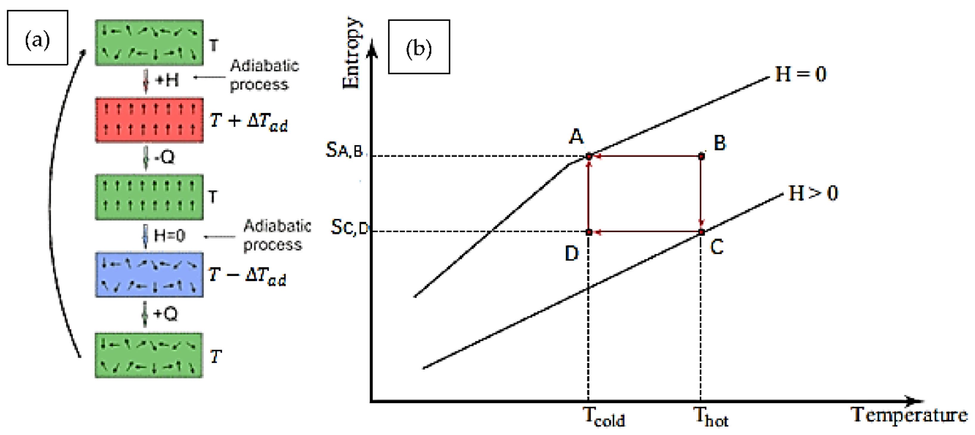
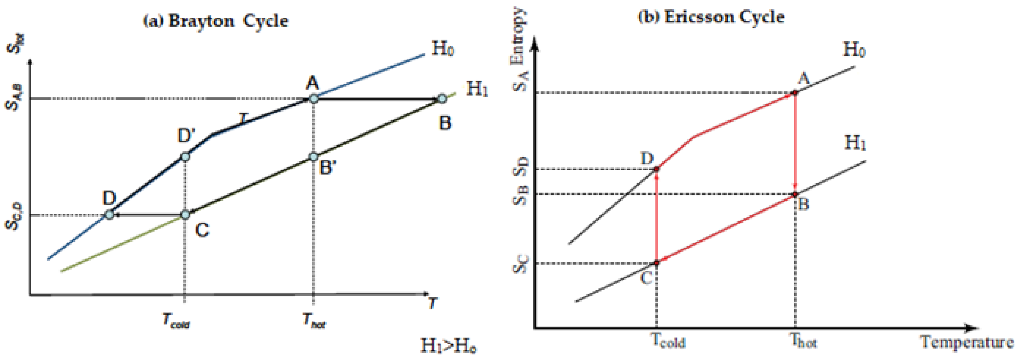
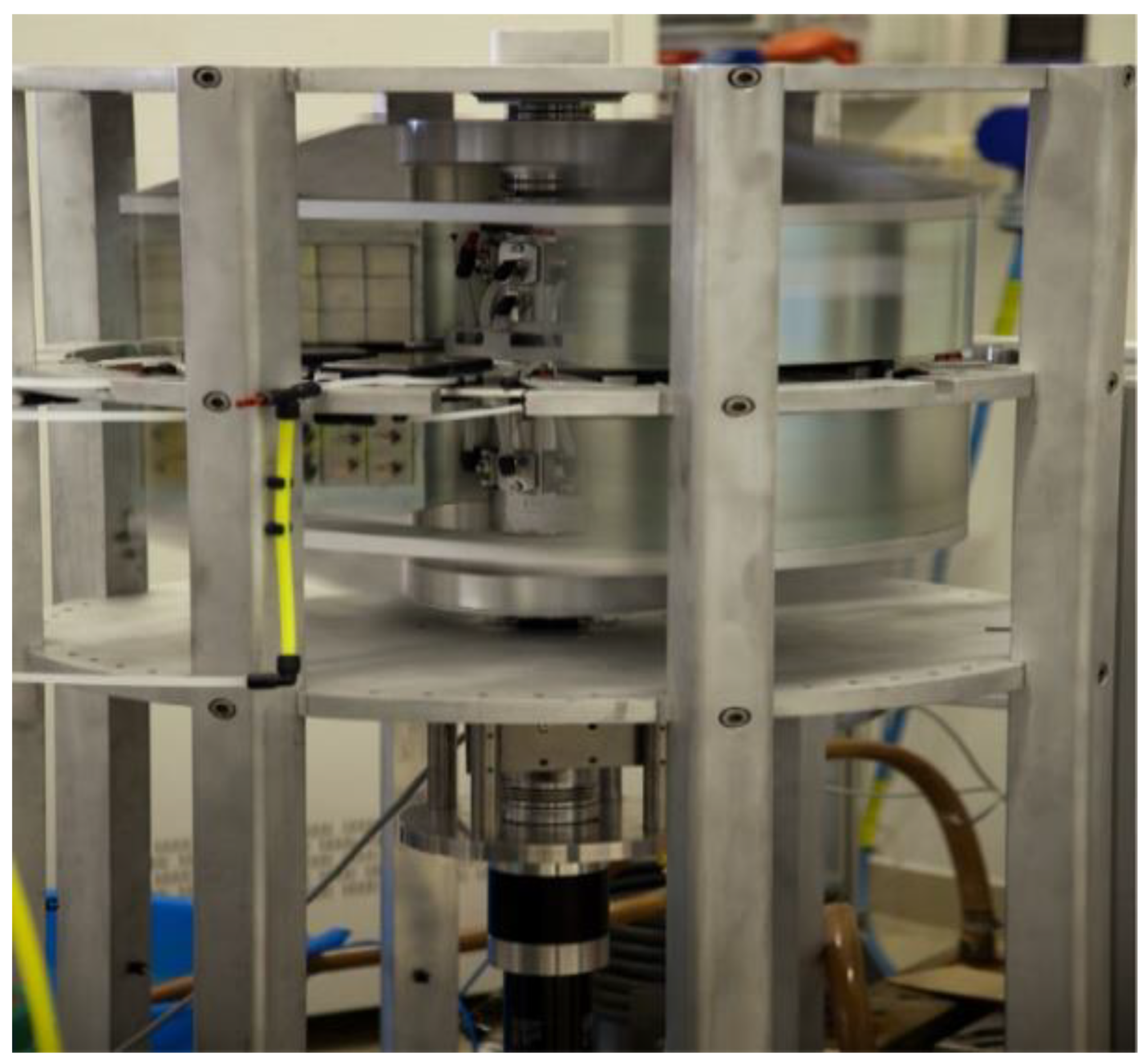
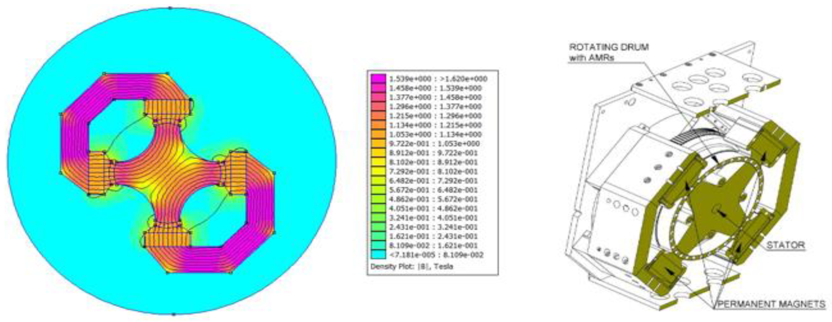
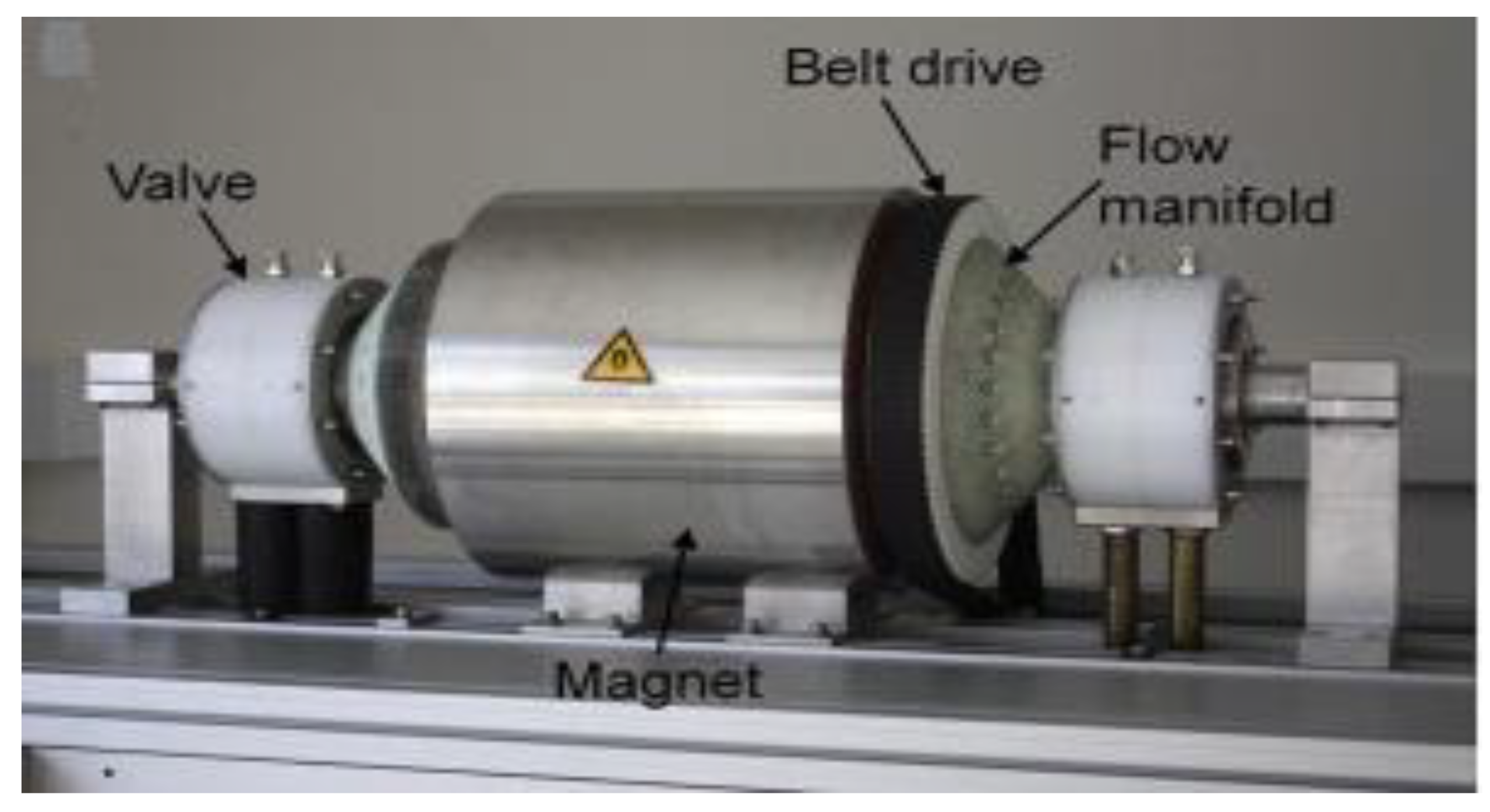
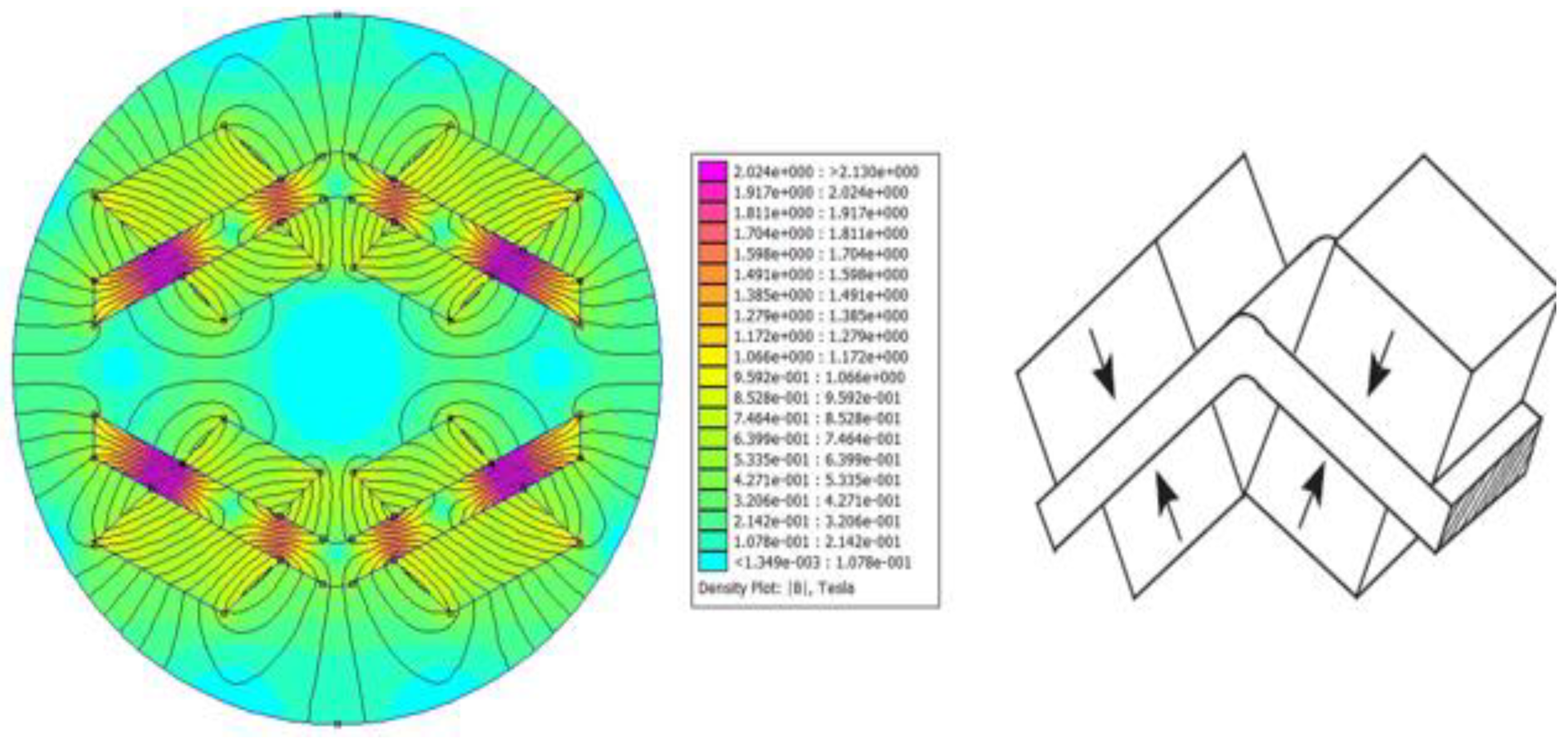
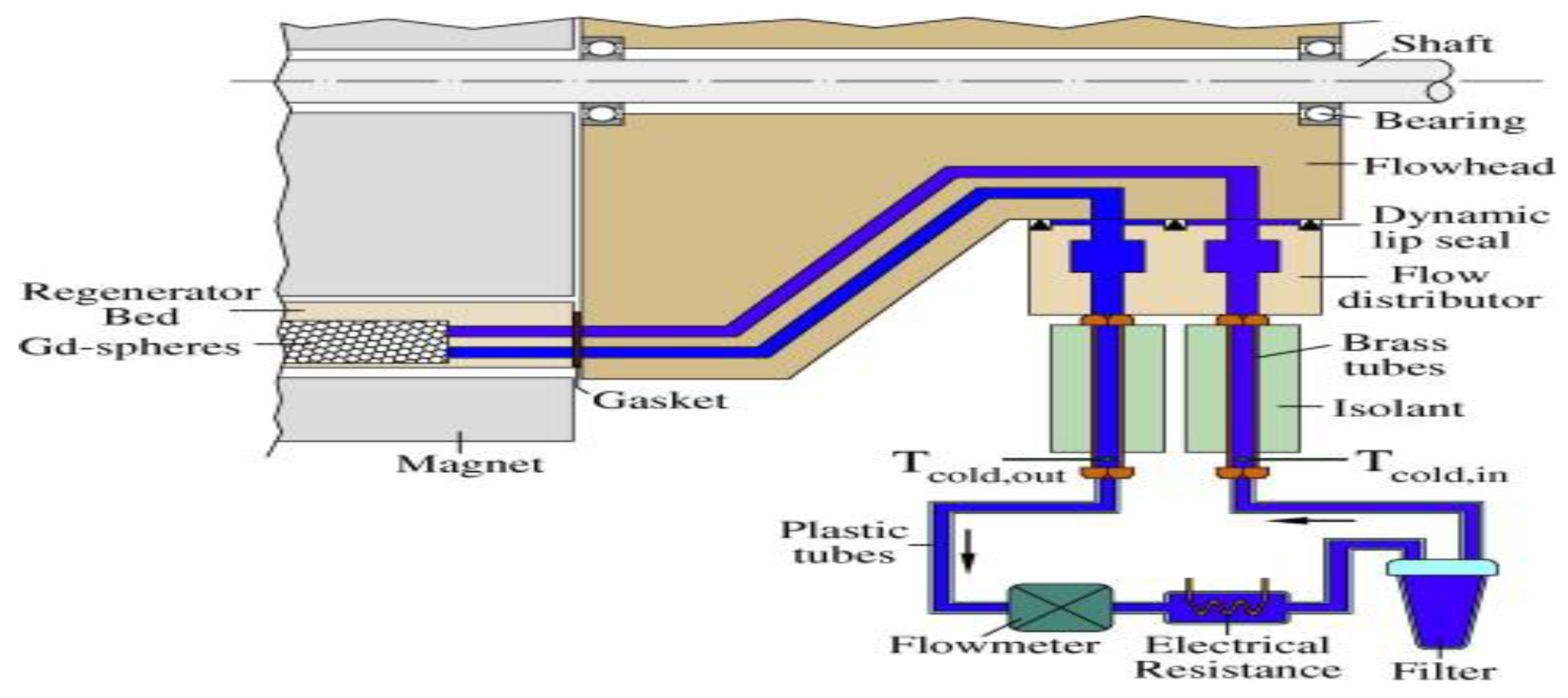
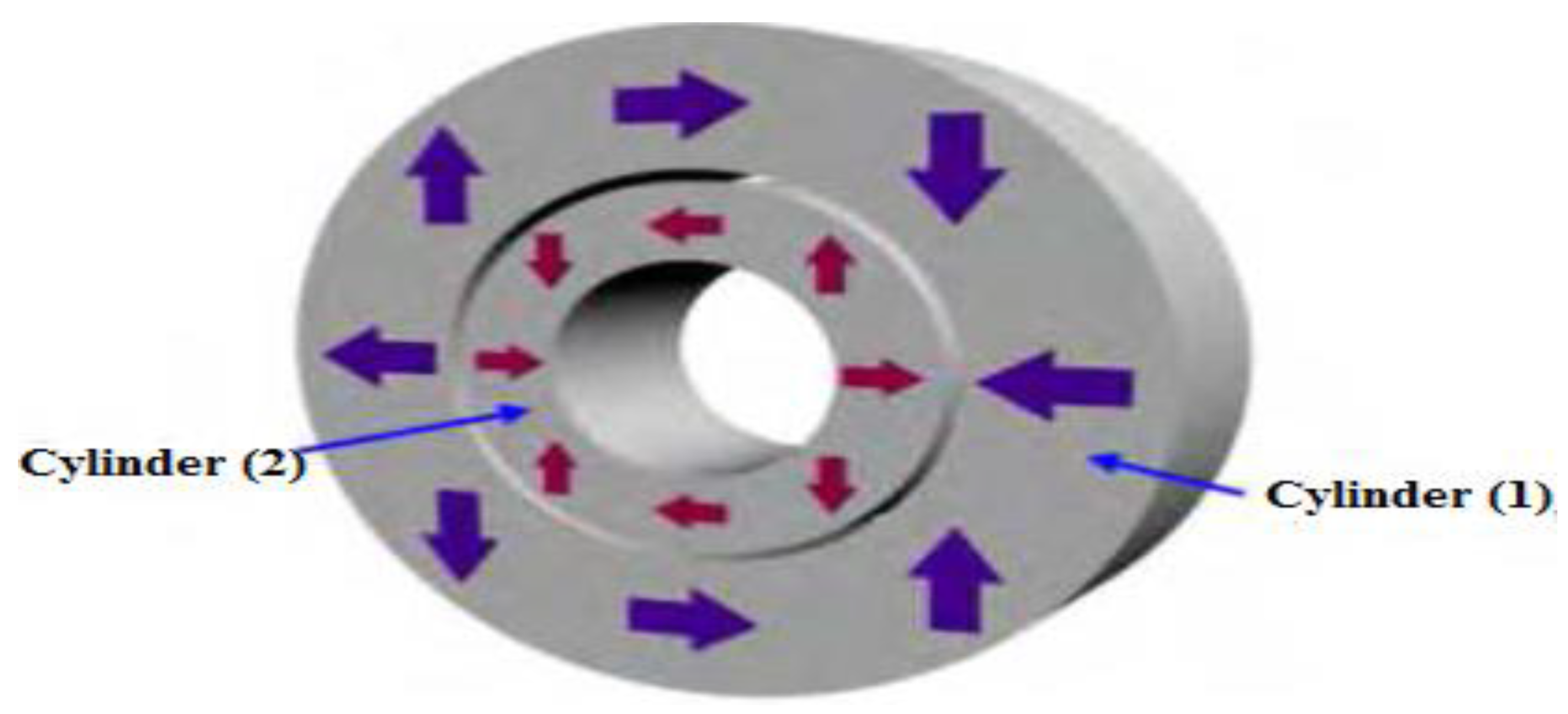
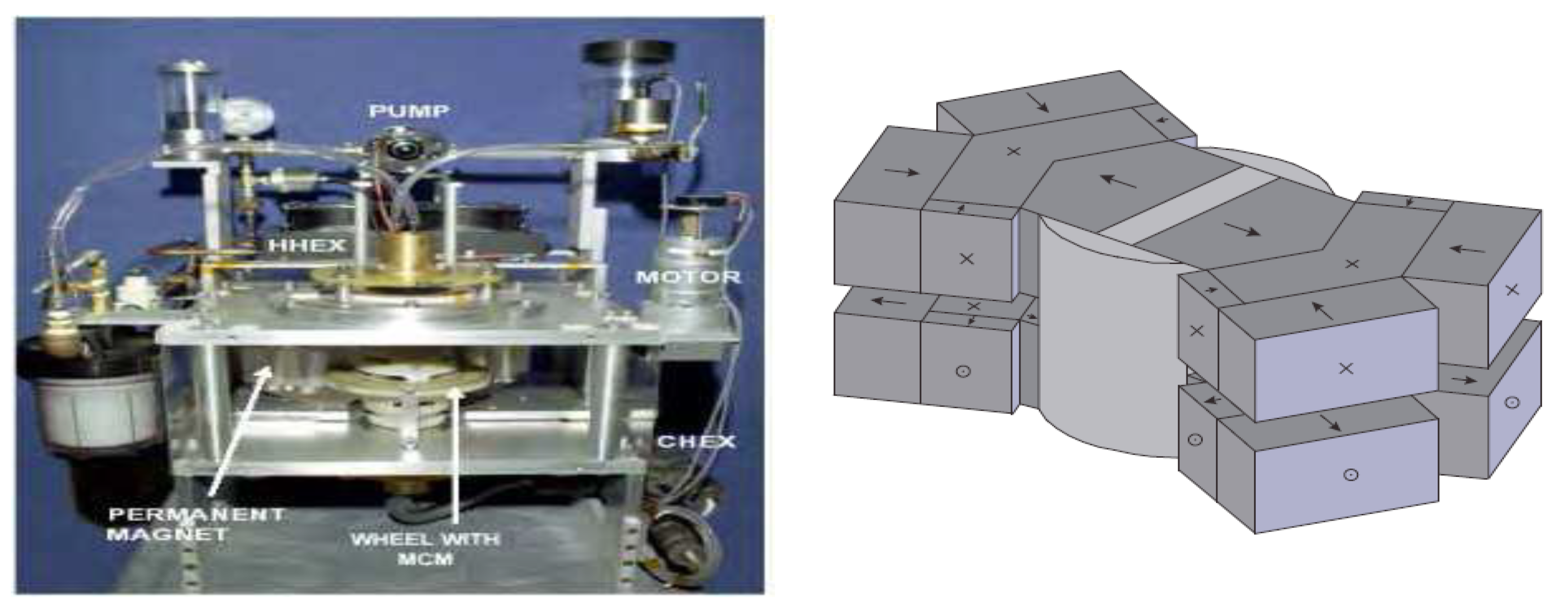
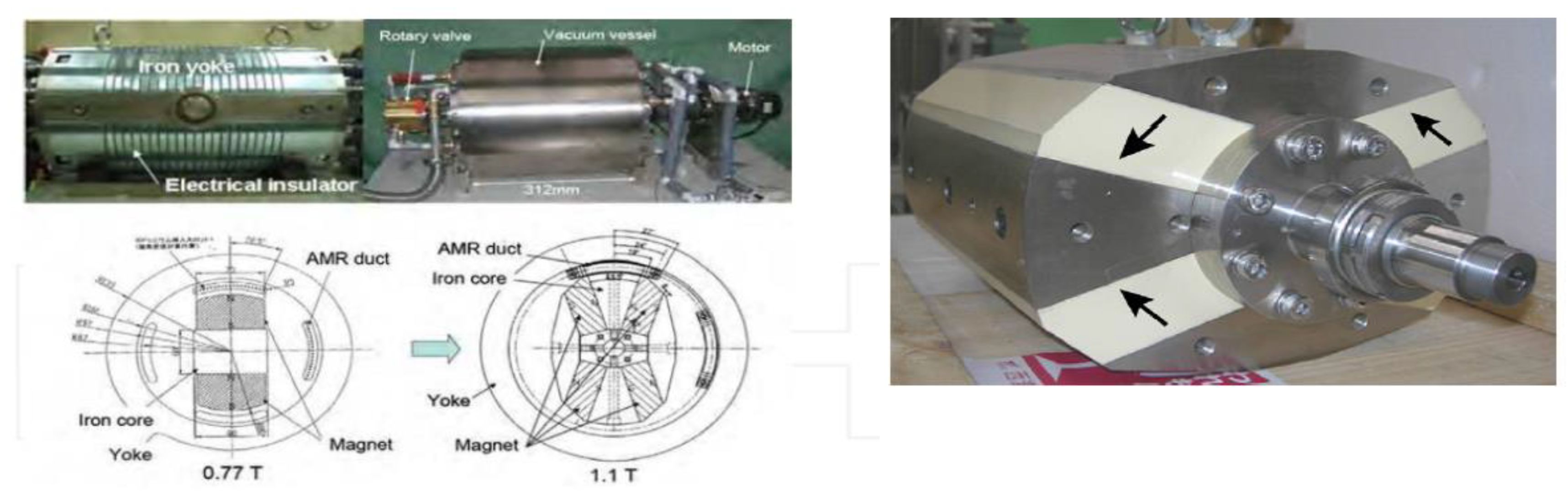
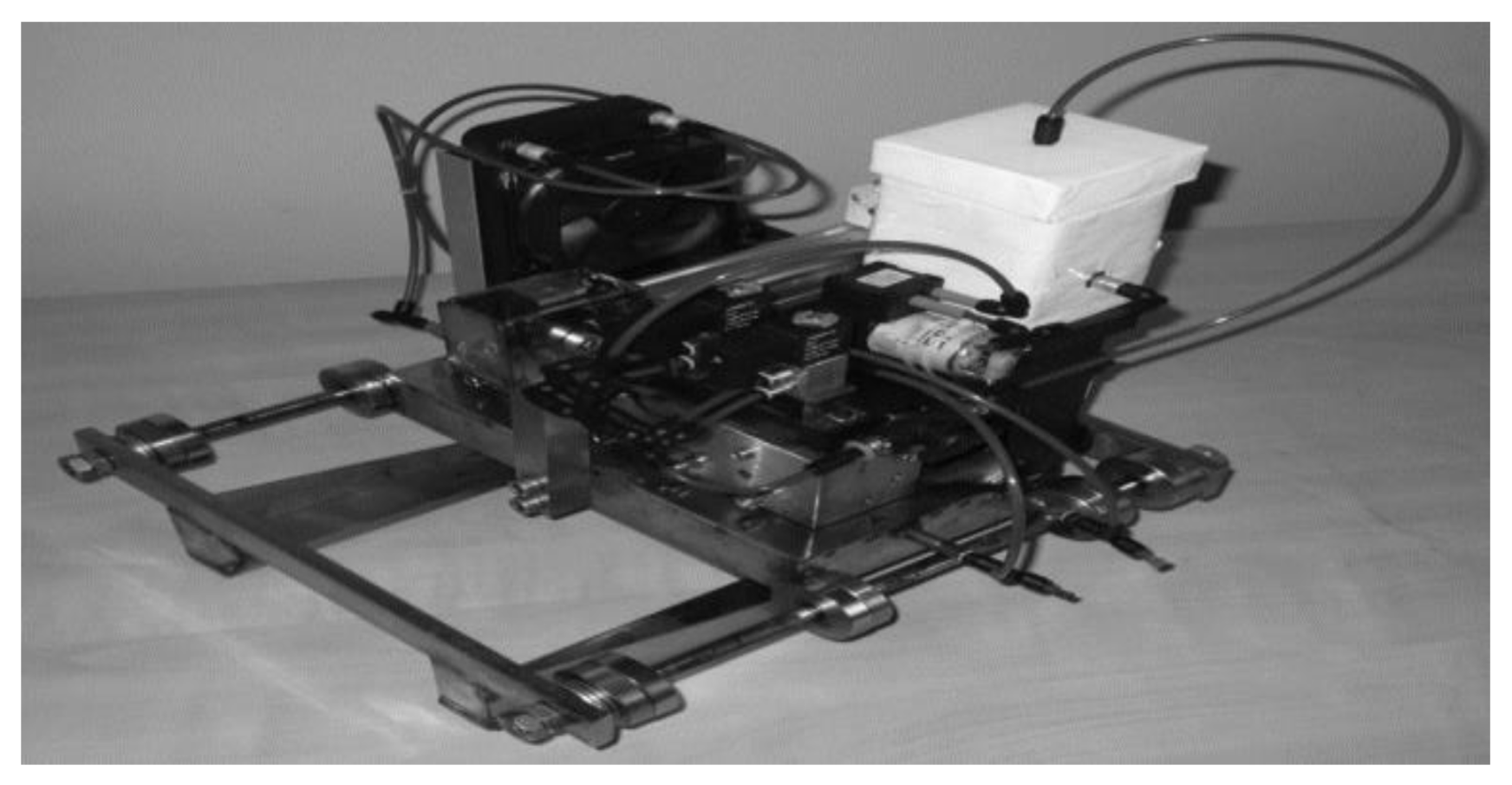
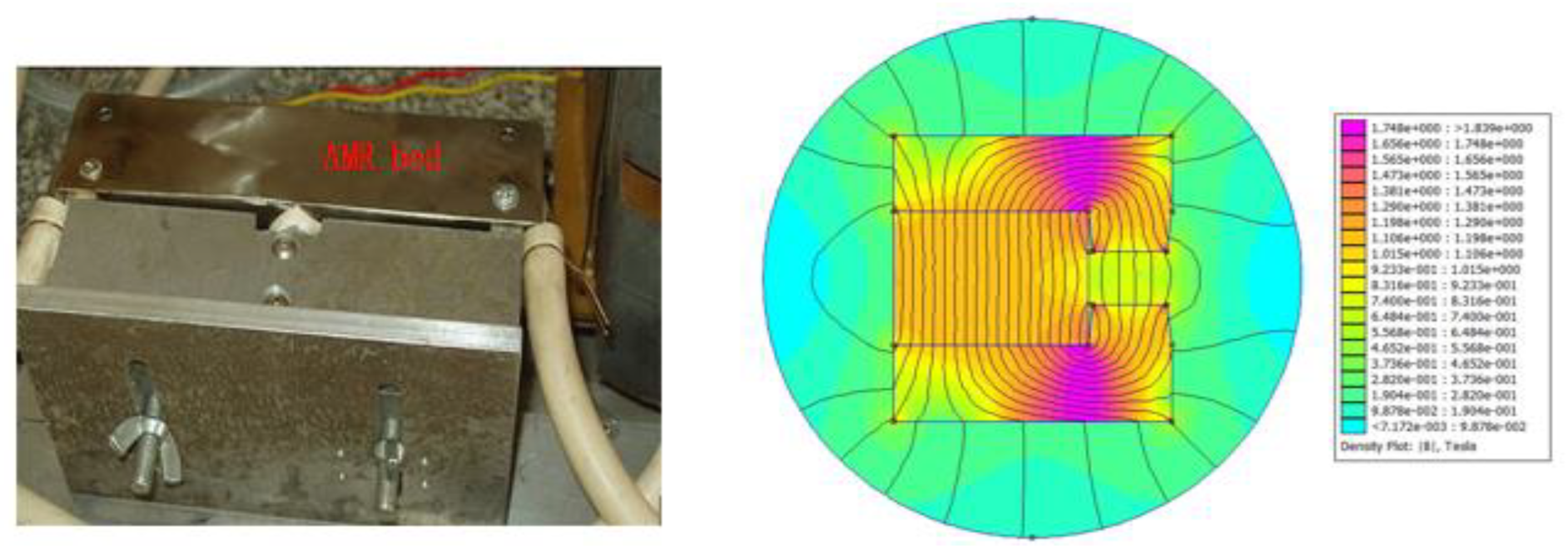
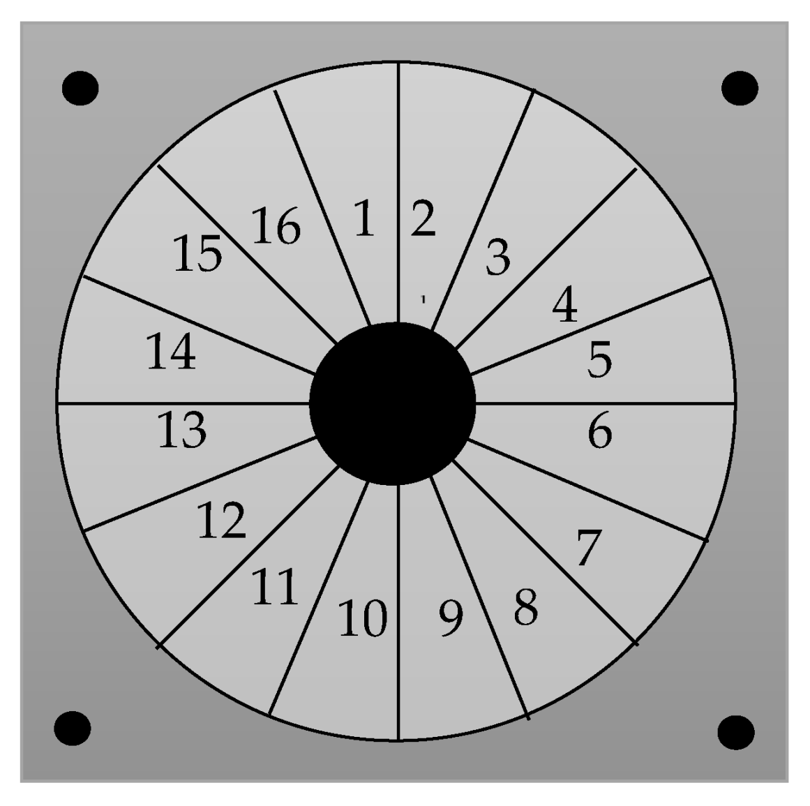
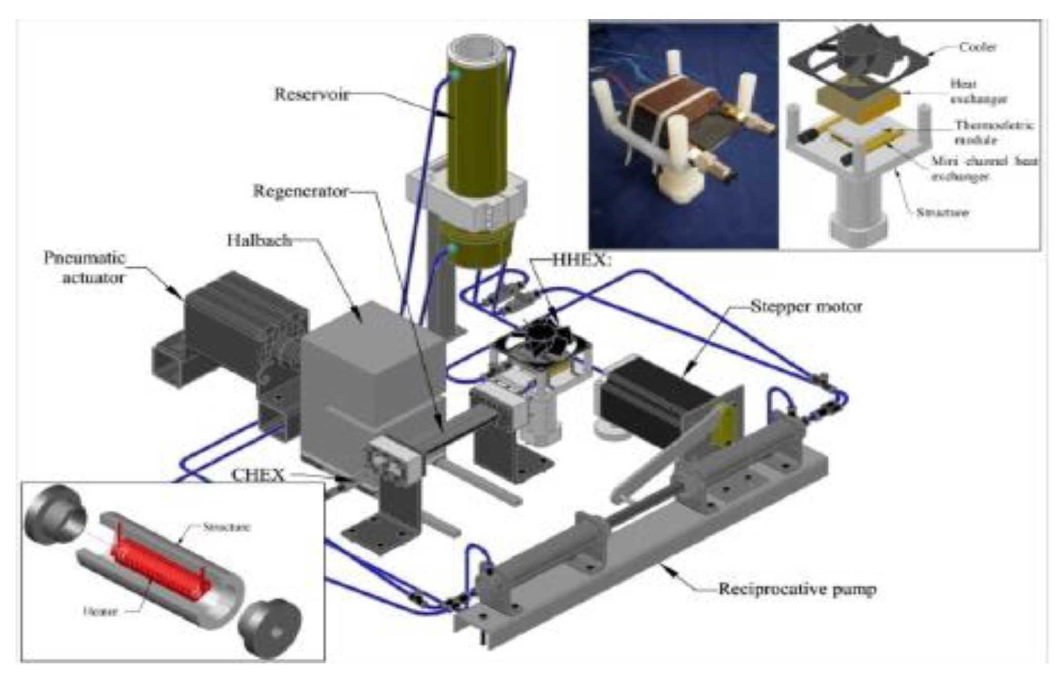
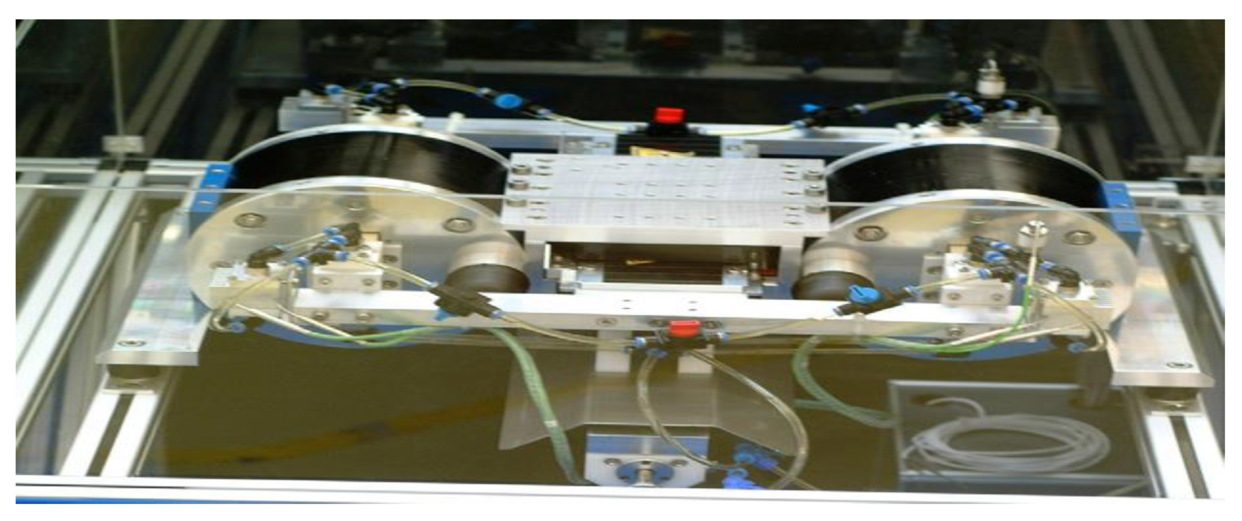
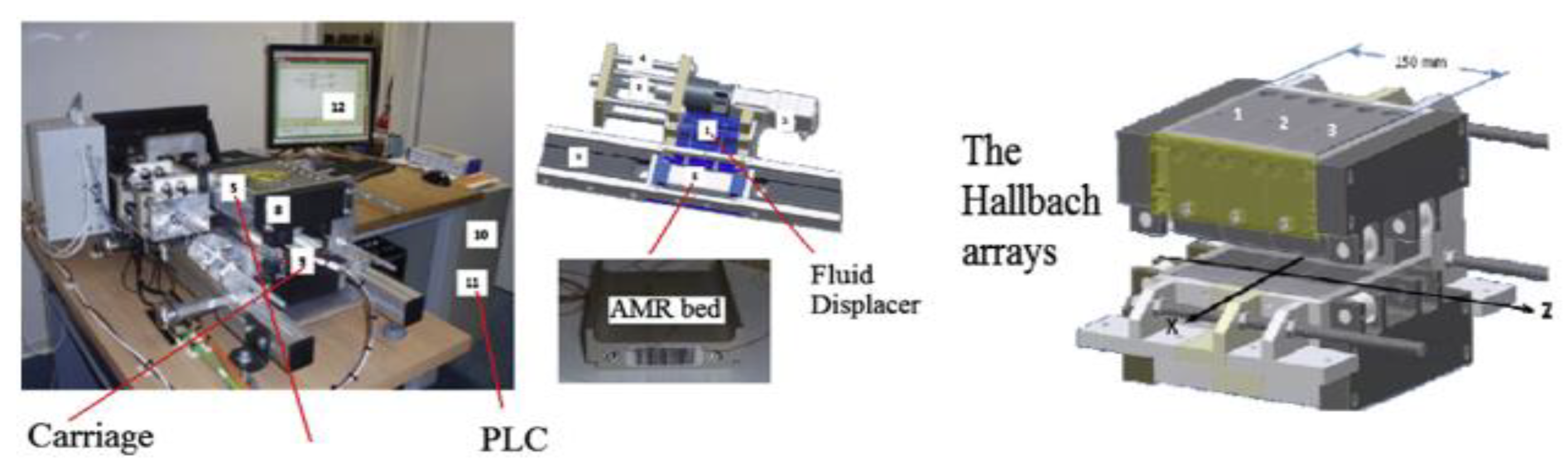
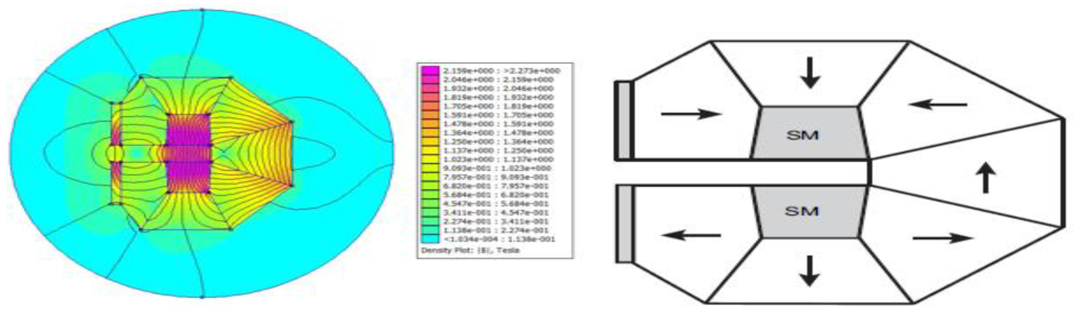
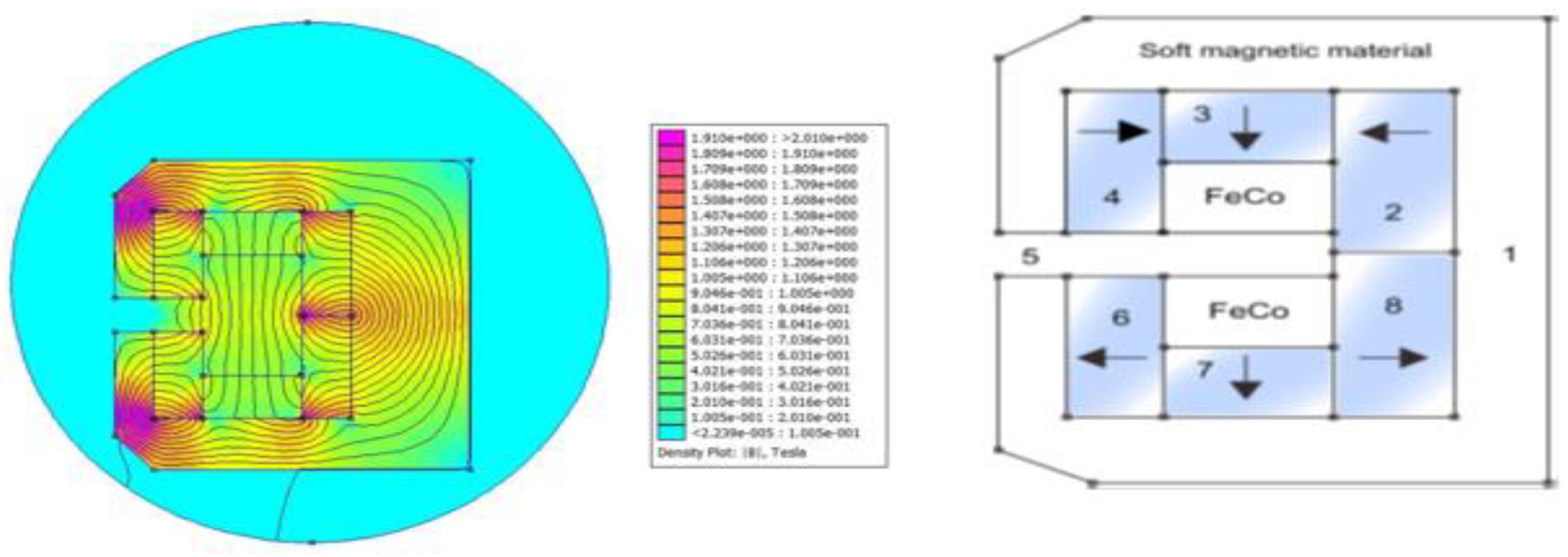
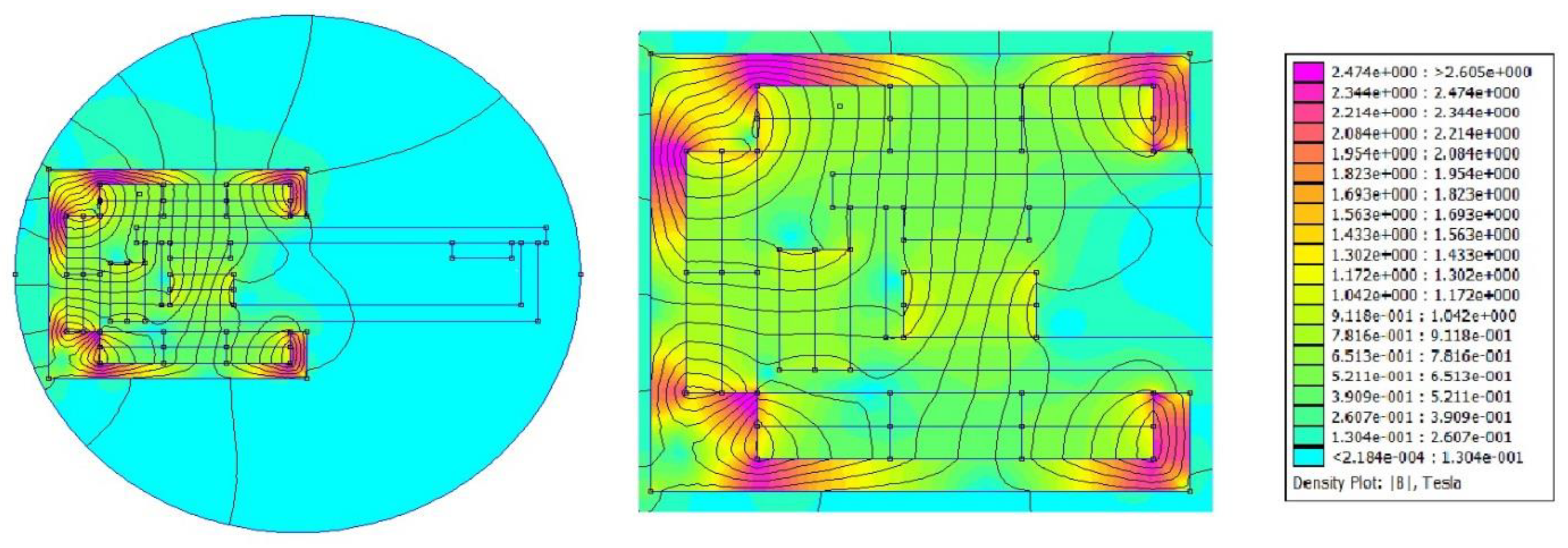
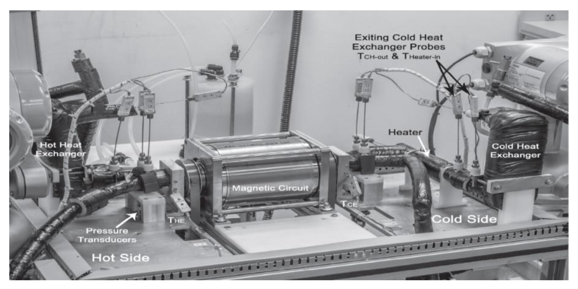
Table 1.
Main attributes and applications for different emerging refrigeration technologies [22,23,24,25,26,27,28,29,30].
| Solar Adsorption | Magnetic Refrigeration | Acoustic Refrigeration | |
|---|---|---|---|
| Principles | To generate cooling, use low-temperature heat that is powered by solar energy. | To achieve a cooling effect, some materials have a unique property called the magnetocaloric effect (MCE). | Acoustic or sound waves are used to generate cooling. |
| Advantages |
|
|
|
| Disadvantages | Adsorption chillers have a low COP and high manufacturing expenses |
| In comparison with traditional refrigerator technologies, it has a lower thermal efficiency |
| Obstacles | The adsorption chiller’s low efficiency of COP and specific cooling power (SCP) prevent its commercialization |
|
|
| Applications | Food processing, cold storage, retail, and refrigerated transport |
| Domestic and commercial refrigerators, freezers, natural gas liquefaction, chip cooling, and cooling of electronic devices |
| COP | 0.4–0.7 | 1.8 at room temperature | Up to 1.0 |
Publisher’s Note: MDPI stays neutral with regard to jurisdictional claims in published maps and institutional affiliations. |
© 2021 by the authors. Licensee MDPI, Basel, Switzerland. This article is an open access article distributed under the terms and conditions of the Creative Commons Attribution (CC BY) license (https://creativecommons.org/licenses/by/4.0/).
Share and Cite
MDPI and ACS Style
Alahmer, A.; Al-Amayreh, M.; Mostafa, A.O.; Al-Dabbas, M.; Rezk, H. Magnetic Refrigeration Design Technologies: State of the Art and General Perspectives. Energies 2021, 14, 4662. https://doi.org/10.3390/en14154662
AMA Style
Alahmer A, Al-Amayreh M, Mostafa AO, Al-Dabbas M, Rezk H. Magnetic Refrigeration Design Technologies: State of the Art and General Perspectives. Energies. 2021; 14(15):4662. https://doi.org/10.3390/en14154662
Chicago/Turabian StyleAlahmer, Ali, Malik Al-Amayreh, Ahmad O. Mostafa, Mohammad Al-Dabbas, and Hegazy Rezk. 2021. "Magnetic Refrigeration Design Technologies: State of the Art and General Perspectives" Energies 14, no. 15: 4662. https://doi.org/10.3390/en14154662
Note that from the first issue of 2016, this journal uses article numbers instead of page numbers. See further details here.