
Modular Multilevel Converters for Large-Scale Grid-Connected Photovoltaic Systems: A Review


1
Department of Engineering, Lancaster University, Lancaster LA1 4WY, UK
2
Department of Electrical Engineering, Engineering College, Shaqra University, Riyadh 11961, Saudi Arabia
*
Author to whom correspondence should be addressed.
Energies 2021, 14(19), 6213; https://doi.org/10.3390/en14196213
Submission received: 3 September 2021
/
Revised: 24 September 2021
/
Accepted: 25 September 2021
/
Published: 29 September 2021
(This article belongs to the Special Issue Modular Multilevel Converter for Photovoltaic Applications)
Abstract
:The use of photovoltaic (PV) systems as the energy source of electrical distributed generators (DG) is gaining popularity, due to the progress of power electronics devices and technologies. Large-scale solar PV power plants are becoming the preferable solution to meet the fast growth of electrical energy demand, as they can be installed in less than one year, as compared to around four years in the case of conventional power plants. Modular multilevel inverters (MMIs) are the best solution to connect these large-scale PV plants to the medium-voltage (MV) grid, due to their numerous merits, such as providing better power quality, having higher efficiency, providing better reliability, and their scalability. However, MMIs are still progressing and need some improvement before they can be implemented safely in the industrial, medium, and high voltage networks. The main purpose of this paper is to review the present MMIs topologies when used in PV applications. The review aims to present a comprehensive study of the various recent submodule circuits associated with MMI topologies. Maximum power point tracking (MPPT) control schemes for PV inverters will be explored extensively. Then, the different control strategies of PV MMIs will be presented and compared to give a holistic overview of the submodules balancing techniques, ranges, and capabilities under balanced and unbalanced grid conditions. In addition, the paper will discuss the future of PV MMIs systems in electricity networks.
1. Introduction
The increasing insistence by policy makers in different countries to heal the continuous and irreversible damage to our planet’s ecosystem caused by burning fossil fuels has led to an increased interest in renewable sources in both the energy and transportation sectors. Solar photovoltaic (PV) energy generation systems are becoming more popular, as part of this expansion depends upon various distributed energy resources (DERs) [1]. Global PV expansion is going to increase rapidly due to the improvements in power electronics technologies and the cost reduction of the PV modules, making PV systems an attractive solution for cheap energy source that can be constructed and enter into service in less than 1 year [2]. It has been reported by the International Renewable Energy Agency (IRENA) in 2020 that the average price of PV modules has been reduced by around 85% in the last decade [2]. The price has been reduced by 13% in 2019 only to around 5p per 1 kWh. Accordingly, the new installed PV power plants are expected to have lower cost than the existing coal-based plants, in the near future. The cumulative global PV capacity in 2020 was around 707 gigawatts (GW) with an increase of around 90 GW in 2019 only. More than 627 GW of distributed PV capacity has already been deployed in residential, commercial, and utility-scale projects [3,4].
China has the highest share of the solar PV market, with more than 35% in 2020, more than 253 GW in total. The United States of America (USA) is second, after china, with around 10% of the total market, as generation was around 74 GW [5]. Middle Eastern and North African (MENA) countries have the potential for a huge investment in the near future. Presently, the United Arab Emirates (UAE) has the biggest share of this market, with 2.4 GW [2]. Egypt built the 1.8 GW Benban solar park in 2019, which is expected to be followed by similar projects [5]. In general, there is a significant increase in investments in the renewable energy field, which includes photovoltaic solar energy sources. These investments are beneficial for both the private and public sectors in order to supply the required energy to industrial and residential customers from clean energy sources [6]. The recent scientific progress offered by the new semiconductor devices and other electrical devices creates a great opportunity for the implementation of future technologies and systems that will impact everyone’s life [7]. International PV markets are progressing rapidly with respect to the electric energy sector’s competitiveness. The drop in PV systems’ price pushes forward “dynamic grid parity”, which occurs when the savings in electrical power price are equal to or higher than the initial cost of the PV system [8]. This competitiveness is being achieved progressively in the European Union (EU) countries. It is estimated that PV systems could cover up to 15% of the electricity demand in 2030, about 400 GW. Recent studies in the EU recommend more active support from policymakers, regulators, and the power sector in order to enable the EU to increase its share of PV and meet its goal [9]. Great benefits will be obtained if deep PV penetration in the electricity grids takes place early [9]. The mass penetration of PV systems will support the competitiveness of the EU markets, increase employment, and provide a greater power security [5].
The distributed PV systems can be divided into three groups based on their power output:
- Small-scale systems, who’s output power is up to 250 kilowatts; typically, this type of PV system is common in the residential sector, where solar panels are located on rooftops [10].
- Commercial-scale systems, with output power ranging between 250 to 1000 kilowatts [11].
- Large (or utility)-scale systems, with output power ranging higher than 1 MW [12].
Large-scale PV systems are the preferred solution for rapid multi-megawatt energy systems to supply the electricity demand, especially in rural areas, as they can be built and operated in less than 1 year, compared to the approximately 4 years required for conventional electricity power plants at the same power [13,14]. In the traditional large-scale PV plant shown in Figure 1, the PV modules are connected in a series/parallel combination to form a PV array, which is then connected to a DC/DC converter. The outputs of the PV arrays’ DC/DC converters are connected to a common DC bus at the range of 415–690 V. A centralized DC/AC inverter is connected to the common DC bus to transfer the electrical power to the MV AC grid through a step-up transformer, which is necessary to boost the voltage from the common DC bus level to the MV grid level [15,16].
As this step-up transformer operates at the line frequency, which is usually 50/60 Hz, it has a huge size and weight to avoid saturations and their cores’ heating. For example, a three-phase, oil-filled, 0.4-kV/35.5 kV, 2-MVA transformer weighs 6100 kg and has the volume of 11.3 m3 [17]. In addition, the centralized DC/AC inverter transfers the full power of the system, which means that the voltage and current stresses on the semiconductor switches will be very high. A single failure in this centralized inverter will lead to a full shutdown of the entire plant [18]. Usually, the conventional three-phase two-level voltage source inverter (VSI) is used in this application and therefore the input and output currents will be discontinuous, and large filtering elements are required to reduce current ripples and eliminate electromagnetic interference (EMI) [19]. The voltage rating of the insulated gate bipolar transistors (IGBTs) in the market is still around 6.5 kV. Furthermore, these devices should be de-rated by a factor of 0.5 to consider the device commutation voltage and increase the reliability of 100 failures in time (Vcom@100FIT) [20]. This limits the VSI voltage to 3.25 kV. A series connection of IGBTs can also create challenges, due to the problems caused by the mismatch of the IGBT devices characteristics with gate-driver circuits, and, hence, additional snubber circuits are required, which complicates the operation [21]. From the PV arrays’ side, if many PV modules are connected in series to boost the voltage from PV arrays’ size, the maximum power extraction from the PV modules will be challenging in the case of the partial shading of some modules, which will, in turn, reduce the harvested energy from the system [16]. The following points should be considered in the designing of a futuristic large-scale PV plant: (1) galvanic isolation is necessary between the input PV arrays and the MV grid for safety reasons and to eliminate the common-mode voltages and currents; (2) the power-semiconductor devices’ ratings and losses; (3) maximum power extraction during shading; and (4) the sizes and weights of the step-up transformer and passive filters [22,23].
In this context, modular multilevel inverters (MMIs) emerge as a potential solution to solve the problems and improve the performance of large-scale PV systems. There is an increasing interest in AC module systems with a series-connected multilevel structure, in recent years, to maximize harvested power and improve the efficiency of these large-scale PV systems when integrated into the MV grid [24]. MMIs provide the required modularity and scalability, which means that a large-scale PV system can generate high power with smaller semiconductor devices, as their inverter modules will be scaled up [25]. Moreover, it is possible to replace the bulky and heavy transformer with a smaller isolation transformer, operating at high or medium frequencies instead of the grid’s low frequency [26]. MMIs provide a better fault-ride-through operation when compared with the traditional centralized systems, which will, in turn, increase the reliability of the plant [16]. Furthermore, MMIs have better total harmonic distortion (THD) performance, compared wtih existing low-voltage converters, and, hence, the size and weight of the required filters can be reduced [27].
The term “multilevel” was first used to describe the three-level converters but it was later expanded to include many other inverter topologies. The main topologies of the MMIs family are neutral point clamped (NPC), flying capacitor (FC), cascaded H-Bridge (CHB), and modular multilevel converter (MMC) [28]. Each MMI faces unique obstacles that necessitate additional design considerations when used in the field of PV systems [29]. This paper presents an overview of recent MMIs topologies, their technological challenges, and their requirements when used in the context of PV systems, and explains the benefits and the drawbacks of each type. The work is structured as follows: Section 2 describes the topologies of MMIs and provides a comparative study between the different structures. Section 3 reviews a variety of relevant multilevel inverters and how they were favored over others in the field of PV systems. Section 4 discusses controllers, including their classification, operation, strengths and weakness points, and balancing strategy performance. Then, the paper discusses current PV systems’ developments and future trends in Section 5. The conclusions are finally drawn in Section 6.
2. Modular Multilevel Inverters (MMIs)
Several MMIs topologies are gaining popularity in high-power applications, including MV motors applications, solid state transformers, grid-connected wind, and solar PV systems. However, most of the MMIs are designed for either high voltage transmission (HVDC) networks or offshore wind energy systems [30,31]. The challenges facing the employment of MMIs in the field of solar PV systems are various. For large-scale solar PV systems, it is necessary to provide galvanic isolation between the input and the output sides of the power converter. Also, the method of extracting the maximum power from the PV modules, using the maximum power point-tracking (MPPT) controllers will affect the operation and the design of the employed MMI [32]. The main goal of the MMI in this case will be to integrate the PV system to the MV grid with maximum harvested power from the sun, guaranteeing safety for personnel and complying with the MV grid’s rules. This is different, for example, to motor drives’ application, where regenerative braking and eliminating the common mode currents are the biggest challenges [16]. The applications wherein an MMI is employed will determine the techniques used to control and modulate its power converter. For example, the sinusoidal pulse width modulation (SPWM) techniques with proportional integral control may be used in solar PV systems, while voltage/frequency control techniques are used in the context of motor drives’ applications [33,34]. The next subsections will present the main MMI topologies used in the context of the MV solar PV plants, with an attempt to provide insightful comparisons, comments, and discussions on the merits and drawbacks of each topology.
2.1. Neutral-Point Clamped (NPC)
The NPC was the first topology to follow the conventional two-level converters. As shown in Figure 2, it adds two switches in each phase and the neutral point of NPC is directly connected to the central point of the switches via two clamping diodes [35]. This results in an additional zero-voltage output level, so the converter will have three voltage levels instead of two. Increasing the number of levels improves the power quality of the output voltage, as the shape will be closer to a sinusoidal waveform [36]. Also, the voltage stress on the semiconductor devices will be reduced, as it is shared by more devices. The of NPC topology is a favored choice for MV motor-drive applications [37]. The ACS 1000 converter, which has a three-level NPC, and the ACS 5000 converter which has a five-level NPC, are the most common two commercially available power converters in industry [38].
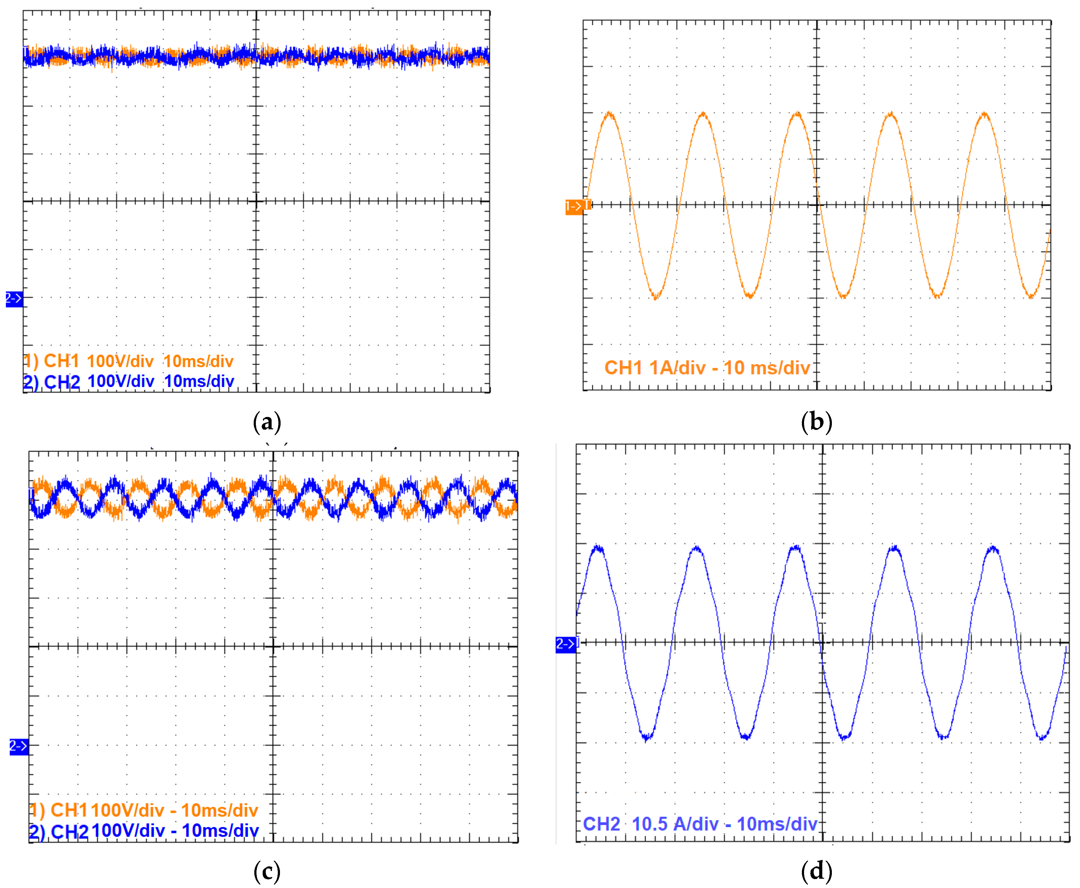
On the downside, the efficiency of the NPC drops significantly with increasing output power. Moreover, the two DC link capacitors exert unbalanced voltages with increasing output power, which leads to the deterioration of power quality by increasing the output voltage’s total harmonic distortion (THD), as shown in the experimental results in Figure 3. This may lead to damaging the switching devices because of the excess voltage breakdown [39]. This problem can be fixed by modifying the modulation scheme to consider the imbalance in the DC link capacitors voltages, but this will increase the complexity and requires additional two voltage sensors to measure the capacitors voltages [40]. Furthermore, with increasing output voltages and hence increasing number of levels, a large number of clamping diodes will be required. This increases the cost, size, and complexity of the modulation and control [41]. Therefore, it forms a major challenge for employing NPCs as MMIs in large-scale PV plants. One publication has proposed a modified active neutral point clamped (ANPC) converter to cope with the consequences of reducing the number of clamping diodes, but it still not suitable for future large-scale solar PV plants with power exceeding 100 MW [38].
2.2. Flying Capacitor (FC)
The FC topology, shown in Figure 4, is a modified version of the NPC, wherein the clamping diodes are replaced by auxiliary capacitors that determine the number of output voltage levels [42]. An FC-based inverter can be modularized and expanded to handle larger voltage levels and higher power density. Although it is cheaper than the NPC topology, the FC topology has several drawbacks that limit it from being used as an MMI for a high-power solar PV plant [43]. Firstly, many capacitors will be used to match the voltage of the MV grid, demanding a complex control technique to complete the pre-charged process of the flying capacitors in order to fulfill the voltage-level requirements. Therefore, the operation will be more complex and have higher overall costs at high power levels [44]. Moreover, the FC topology employs a common DC bus formed by a high number of PV modules, connected in series, and, hence, the MPPT operation is centralized, which will have a negative impact on PV-system performance, especially in large-scale PV power plants [16]. ALSTOM has recently introduced a six-level hybrid system for PV applications, based on a hybrid combination of three levels of an FC system and a two-level inverter system that uses an auxiliary balancing circuit to mitigate the effect of pre-charged flying capacitors and voltage regulation challenges [45]. However, this is still not enough to reach the MV grid’s voltage safely. Also, the FC topology, same as the NPC, does not provide any kind of galvanic isolation between the PV arrays and the output side, which is connected to the grid [46]. Therefore, a line-frequency transformer is still needed for isolation. For these reasons, the NPC and FC multilevel converter topologies are not able to fulfill all the requirements of medium- or high-voltage PV applications [16].
2.3. Cascaded H-Bridge (CHB)
CHB-converter topology is a promising candidate as an MMI for large-scale PV applications. CHBs are comprised of a series of cascaded H-bridge cells with separate DC power supplies as their input side [47]. CHB topologies have many attractive features, which make them promising for employment in large-scale PV applications. The scalable structure allows for increasing voltage levels and therefore high voltages can be generated [48]. The modularity provided by the structure allows for increasing the reliability of the full system if any of the series converters unexpectedly fail for any reason. Using semiconductor devices with low voltage and current ratings will reduce their power losses and hence increase efficiency and power density [49].
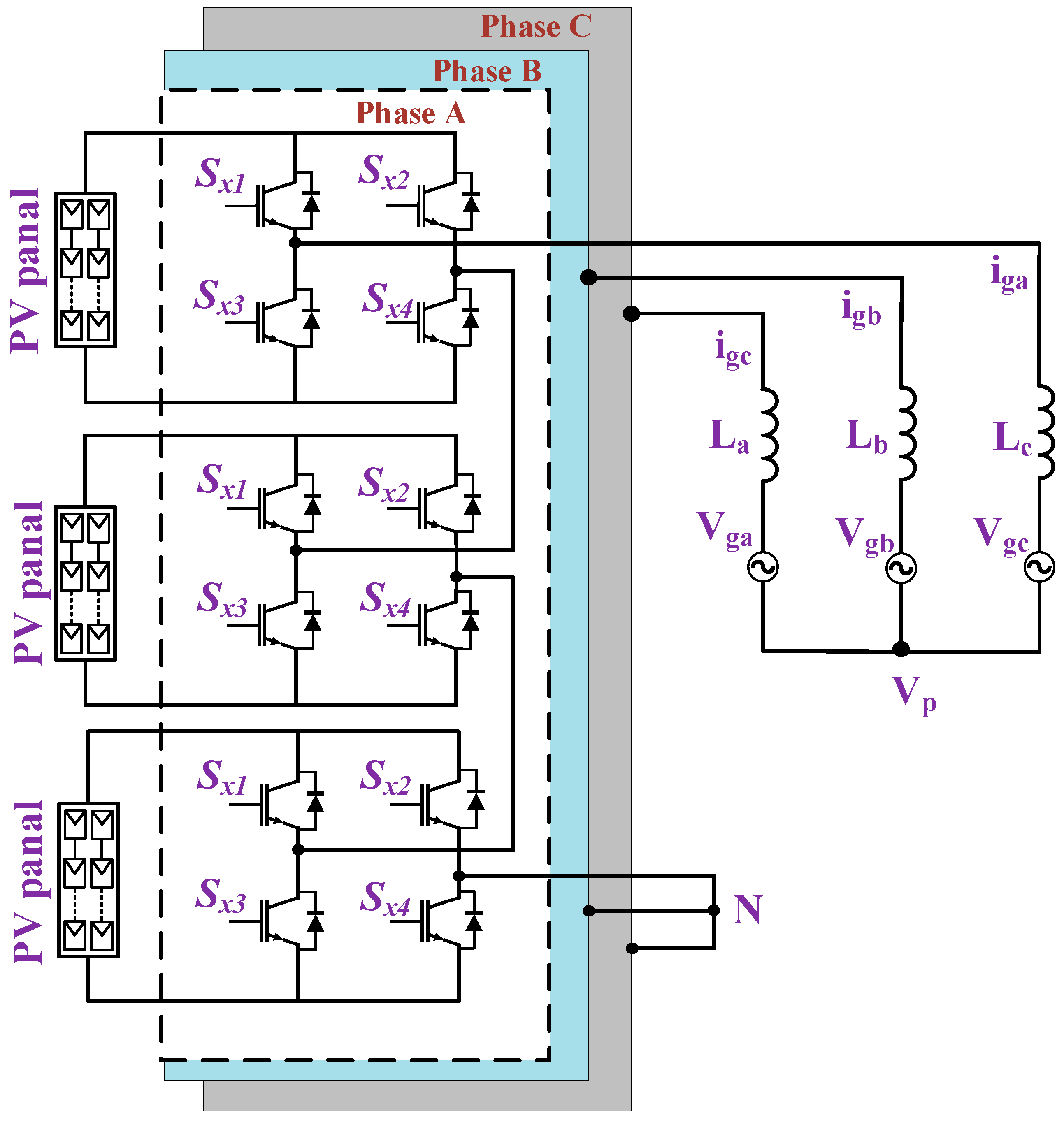
The first type of CHB topology is the conventional three-phase CHB MMI, shown in Figure 5, wherein the inputs of the H-bridges are connected to several PV arrays to provide the required modularization [50]. Therefore, the harvested energy can be maximized by using decentralized maximum-power-point trackers, especially during the partial shading of some modules [51]. The inputs of the H-bridges should be separate DC sources such as PV modules, fuel cells, and batteries. The main drawback of the three-phase MMI from Figure 5 is that it does not provide galvanic isolation between the PV and the MV grids’ sides and, therefore, will require a line-frequency transformer [47,48,49,50,51].
In [52], a three-phase grid-connected cascaded H-bridge multilevel PV inverter is presented wherein the PV array is directly connected to each H-bridge cell to gather the maximum amount of available power, and the PV string is operated at MPPT voltage. Thus, few PV arrays will be connected in series to form a DC source for each H-bridge. This manner of connection can improve solar PV systems’ efficiency because each PV string operates independently, with its own control, and consequently better MPPT performance can be obtained [47,53]. However, the power imbalance of the converter during partial shading should be considered. Moreover, as the number of PV units increases, the system will become more expensive and the control will be complicated [54,55].
The work in [56] shows another version of the CHB MMI, which reduces the switch count by adding an auxiliary circuit, shown in Figure 6, for an PV system integrated with the grid. However, it still lacks the necessary isolation for a PV system and a grid connection, and, hence, leakage currents are high. With the absence of electrical isolation, parasitic capacitances accumulate between the PV arrays and the ground, causing damage and posing a safety issue.
Further development of CHB topology is presented in [57,58] by using the isolated current-fed dual active-bridge (CF-DAB) DC–DCDC–DC converters to connect cascaded H-bridge cells to PV modules. The CF-DAB, shown in Figure 7, will offer the required galvanic isolation, voltage-boosting by the isolating transformer, and will create an additional degree of freedom in controlling the power from the PV modules. Furthermore, small, filter capacitors can be used to reduce the input current ripples from PV converters instead of using large, electrolytic capacitors, which are the most unreliable component in power converters [34].
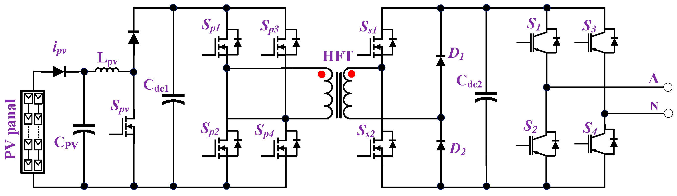
The forward dual-active bridge (F-DAB) converter is then presented with small-size high-frequency transformers (HFTs) in this topology as the main converter for MMI CHB topology [59]. This design, shown in Figure 8, provides galvanic isolation for the PV modules, as well as the capability to increase voltage and reduce EMI. Moreover, this topology provides bidirectional power which is required in other applications. In comparison to existing unidirectional converters, F-DABs are preferable, due to their better performance at higher power capacities and better control of their PV modules. On the downside, it is a two-stage converter, which leads to additional power losses, and the addition of more filtering capacitors makes the conversion system bulkier and reduces the converters’ lifetime.
Figure 9 shows the structure for the CHB MMI topologies based on DC/DC converters at the input side.
A new PV system design with a modified CHB converter based on a cycloconverter was developed for multilevel CHB topology [60]. In this system, shown in Figure 10, a full-bridge inverter is employed to convert the DC voltage to AC. The voltage is then increased and supplied through a transformer, with each secondary connected to a full-bridge AC–AC converter to generate output AC voltages. This topology has the potential to enhance performance while reducing the number of power conversion stages. However, incorporating more switching devices to reduce power conversion stages increases total cost.
The deployment of a high number of PV modules causes operational challeng due to significant voltage unbalances among and within the converter’s three phases. These difficulties are intensified with higher ambient temperatures, partial shadow, and non-uniform irradiation [61,62]. Thus, a common DC link has been proposed to alleviate voltage imbalance problem in PV converters. A modular design with a common DC link was suggested in [63], wherein the PV modules and their associated DC–DC converters are connected to a common DC bus. Then, isolated flyback DC–DC converters serve as the active front-end for each port to ensure galvanic isolation and achieve the MPPT [63,64]. However, fly-back converters have some limitations, as their output current is discontinuous resulting in higher produced harmonics distortion and worse converter efficiency. Moreover, it requires a higher number of conversion stages, resulting in increased costs, weight, and a shorter converter lifespan. This structure is shown in Figure 11.
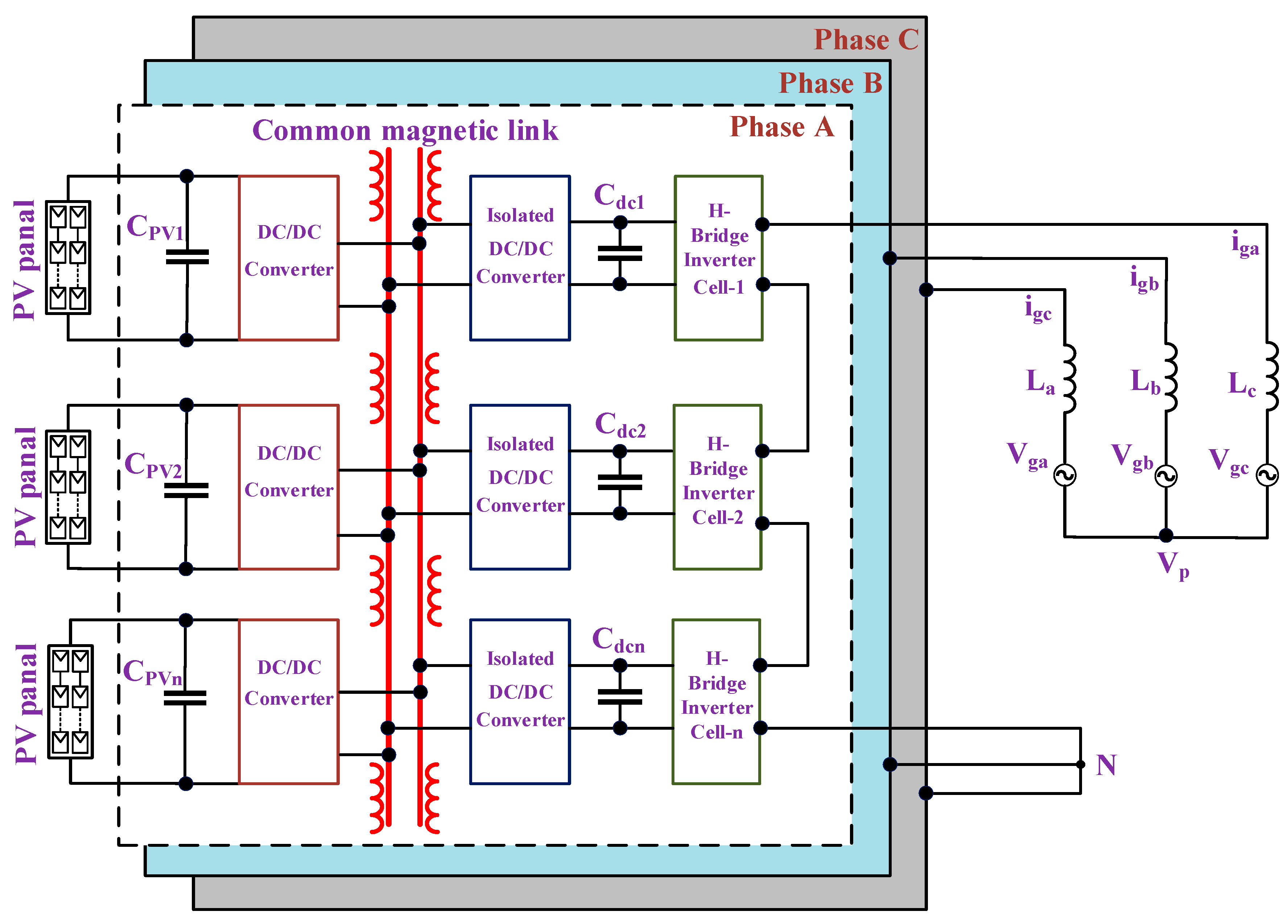
Some studies have discussed the advantages of using a CHB MMI topology with a common high-frequency magnetic link for large-scale PV plants [65,66]. For example, the use of several isolated DC–DC converters and a common DC link can be removed, offering a reduction in the number of conversion stages and improved performance efficiency. The shared magnetic link has been developed to improve of PV modules insulation, handle voltage unbalances, and reduce their impacts on grid currents [14,67]. However, the inverter’s modularity structure, which is one of its main merits, is lost due to the presence of a common magnetic link and, hence, the reliability of the system is degraded. Moreover, the permissible power rating of the inverter topology is limited due to the high leakage inductance during high-frequency switching operations [22]. Magnetic core design and material selection should be carried out carefully to avoid core saturation and reduce core losses. Figure 12 shows a CHB-based MMI with a common magnetic link. Multiple low-power magnetic links provide the possibility of replacing a single common magnetic link, increasing modularity and lowering leakage inductances. A modular PV converter synthesizing five-level CHB topology with multiple magnetic links was introduced for three-phase grid-connected applications [68]. Several magnetic links connect the H-bridges, each one has a primary winding connected to the PV modules and there are three secondary windings for three-phase grid-connections. However, the presented circuit demands an additional unit with magnet links that increases the converter’s footprint. Thus, magnetic core’s design and cost remain their most significant challenge.
2.4. Modular-Multilevel Converters (MMC)
The possibility of developing a modular multilevel solar PV converter based on the MMC topology was first discussed in [69]. According to several articles, the MMC converter has exceptional performance in high-power applications such as multi-terminal HVDC systems [70,71], motor drives [72,73], offshore wind farms [74,75], and static synchronous compensators (STATCOM) [76,77]. However, MMC topology has not shown the same success in the field of solar PV systems.
MMC topology is comparable to CHB topology in terms of scalability, modularity, fault-tolerance capability, and efficient performance. The main reason why it is not commonly used in PV systems is that it requires a single DC link at the input side [78]. However, there are some attempts to employ MMC in PV applications by modifying its cells. These versions can be classified as MMC with a common DC link [79] and separate PV-array connections that are connected directly to the submodules (SMs) [80,81]. Both versions are shown in Figure 13 and Figure 14.
Also, MMC converters are not extensively used in large-scale PV systems because of shortcomings with its SM design. The traditional MMC SM structure is often developed using half-bridge or full-bridge converter topologies. If employed as a PV MMI, half-bridge-based MMCs will require many separated and balanced PV modules. Furthermore, it is unable to provide DC fault-ride-through capabilities in case of a short-circuit on the input or the output sides [82]. With a full-bridge SM, PV modules can be connected independently and, hence, each module can act as a separate input DC source. However, there will be operational risks because of stray capacitance between the PV array and the ground [27].
Therefore, an isolated DC–DC converter stage is commonly employed in PV inverters and these PV inverters are connected to each SM independently to achieve galvanic isolation and enhanced PV module safety [29]. A simple high-frequency (HF) isolated flyback converter was introduced to connect PV modules to full-bridge SMs, ensuring the PV modules’ grounding and independent MPPT control [80]. Due to this separate MPPT control, the extracted power from the PV modules will be maximized. However, this arrangement increases expense, affects efficiency, and creates problems of power imbalance between the phases [83]. As the flyback converter has a discontinuous input current, PV modules need a large electrolytic capacitor to filter the input currents, affecting the reliability of the system.
Using the same idea of employing a DC–DC converter within an MMC topology, as shown in Figure 13, a dual active-bridge (DAB) isolated converter was utilized to connect PV modules to a half-bridge SMs [84]. This circuit has several advantages, such as an independent MPPT, improved safety because of galvanic isolation, and PV modules’ grounding. On the other hand, this system has severe concerns regarding to the arm’s power imbalances and control complexity [22]. A new medium-voltage MMC converter with half-bridge SMs has been presented, in which the SM DC links are connected to the individual PV array via an isolated single active-bridge (SAB) converter to address the imbalance of power between the upper and lower arms due to partial shading [85]. The authors have proposed a design connecting the upper and lower SMs to their respective PV arrays through isolated SAB converters. In addition, their control technique effectively balances grid currents by introducing DC circulating currents while limiting the AC circulating currents to a minimum and, accordingly, increasing converter stability and lowering MMC losses. However, as the secondary side of the SAB converter is uncontrolled, extra harmonics are introduced at the output, and the converter’s efficiency will be reduced [22].
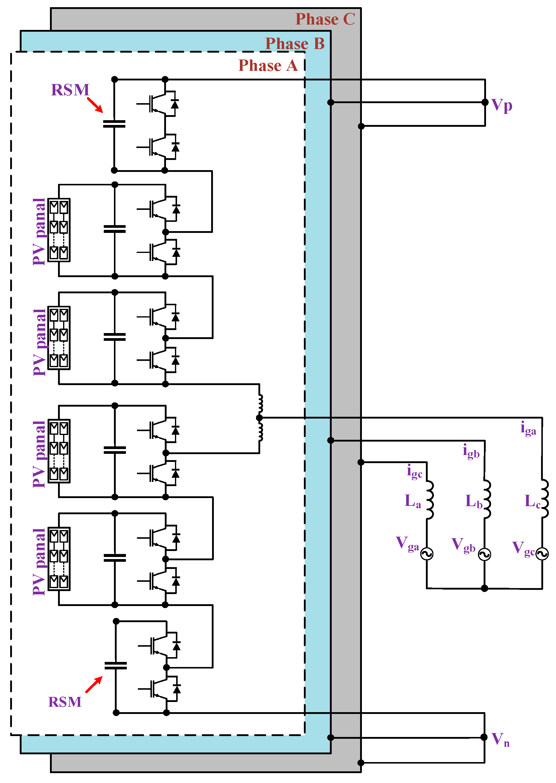
Reference [81] presents a novel topology, shown in Figure 14, in which PV strings are directly incorporated into MMC submodules, allowing independent MPPT control without the complexity of an extra DC–DC converter stage, reducing system costs, and improving efficiency. The topology uses an additional redundant submodule (RSM) on each arm to overcome SM voltage loss during any power unbalance. The proposed structure is optimal for managing bulk power extraction from PV panels under partial shade situations. Even though the MMC-based PV integration is a viable alternative, the huge number of components increases costs and compromises system reliability in the absence of a galvanic separation feature. In [86], a redesigned MMC circuit topology for integrating PV distributed generation systems was presented. The modified design employs an open-end transformer instead of arm inductors and splits the arm inductors into two windings. Thus, lower voltages are needed from the DC bus, the switching device stresses are reduced, and the size of the required SMs capacitor will be smaller. The proposed topology employs PV modules as the MMC’s dc link by increasing the number of PV modules in series and therefore MPPT operation will be complicated. This has a negative impact on the topology’s performance, especially when used in large-scale PV power systems.
3. Alternative Cascaded Modular Topologies
New MMIs have been designed and proposed as alternatives to existing topologies to make them more suitable for PV applications at the MV level. These MMIs are in between the CHB and MMC topologies and hence they will be discussed in this section separately. One of the main concerns facing MMIs when used in PV applications is the leakage currents caused by the parasitic capacitor arising between the PV arrays and the ground, which can harm the PV arrays and create hazards [14,16]. Therefore, an isolated configuration becomes essential to satisfy PV systems’ safety requirements and eliminate leakage currents. To make the MMI suitable for the large-scale PV applications, it is necessary to design a modular system with SMs providing galvanic isolation, reducing voltage and current stresses across the devices, and improving MPPT operation [18,27]. It is necessary also to remove the bulky-low frequency transformer and eliminate the use of electrolytic capacitors as much as possible [86]. Accordingly, several SM circuit topologies have emerged from such constraints. Employing HFTs in these SMs, while operating at high switching frequency (<20 kHz), will reduce their total size considerably and, hence, higher power density is obtained [87]. There is always a trade-off between these requirements and the SM cost, losses, and complexity. These aspects should be taken into consideration when designing high-power MMIs with a large number of SMs.
Several papers have evaluated the progress of the SM designs of isolated converter topologies for PV systems [27,85,87,88,89,90,91]. Reference [27] presented a general structure for modular energy conversion system suitable for the large-scale PV systems, which is shown in Figure 15. The SM converters used in this MMI provide galvanic isolation using small-size HFTs operating at a high switching frequency and, therefore, the size of the system can be reduced significantly. The modular structure is scalable so additional modules with new PV modules can be added easily to increase the power limit using the same structure. As few PV modules are connected to each SM, MPPT operation will be improved, especially in partial shade conditions. The internal isolating transformers provide the required safety and eliminate leakage currents. On the downside, the unbalanced currents in the output sides should be eliminated using advanced control methods. This MMI can use different switched mode power supplies (SMPSs), which will have various advantages and disadvantages. In this study, C5 (Cuk), F5, G5 (SEPIC), and P5 converters are used and tested as SM candidates, as shown in Figure 16 [27,88]. As shown in Figure 15, the PV modules are connected to each of the inputs of the inverter SMs and then the output of these SMs are connected in series to boost the output voltage and allow for direct connection to the MV grid. The voltage and current stresses in the SM inverters are distributed throughout the inverter switches, increasing reliability and lowering power losses.
These specific SMPSs are chosen for this MMI due to their continuous current nature, so that the bulky electrolytic filtering capacitor can be replaced by a compact film capacitor to effectively extend the inverter’s life and improve the system’s reliability [18]. This MMI structure can provide power balancing and operate effectively under shading conditions by modifying the SMs duty ratios. According to the study in [27], the Cuk-based SM is preferable for this MMI as it provides the best efficiency and lowest current ripples. A new SM with a combination of SEPIC/CUK converters has been developed [89]. The proposed design enables the modular connecting of numerous inverter SMs to generate megawatt-scale system outputs.
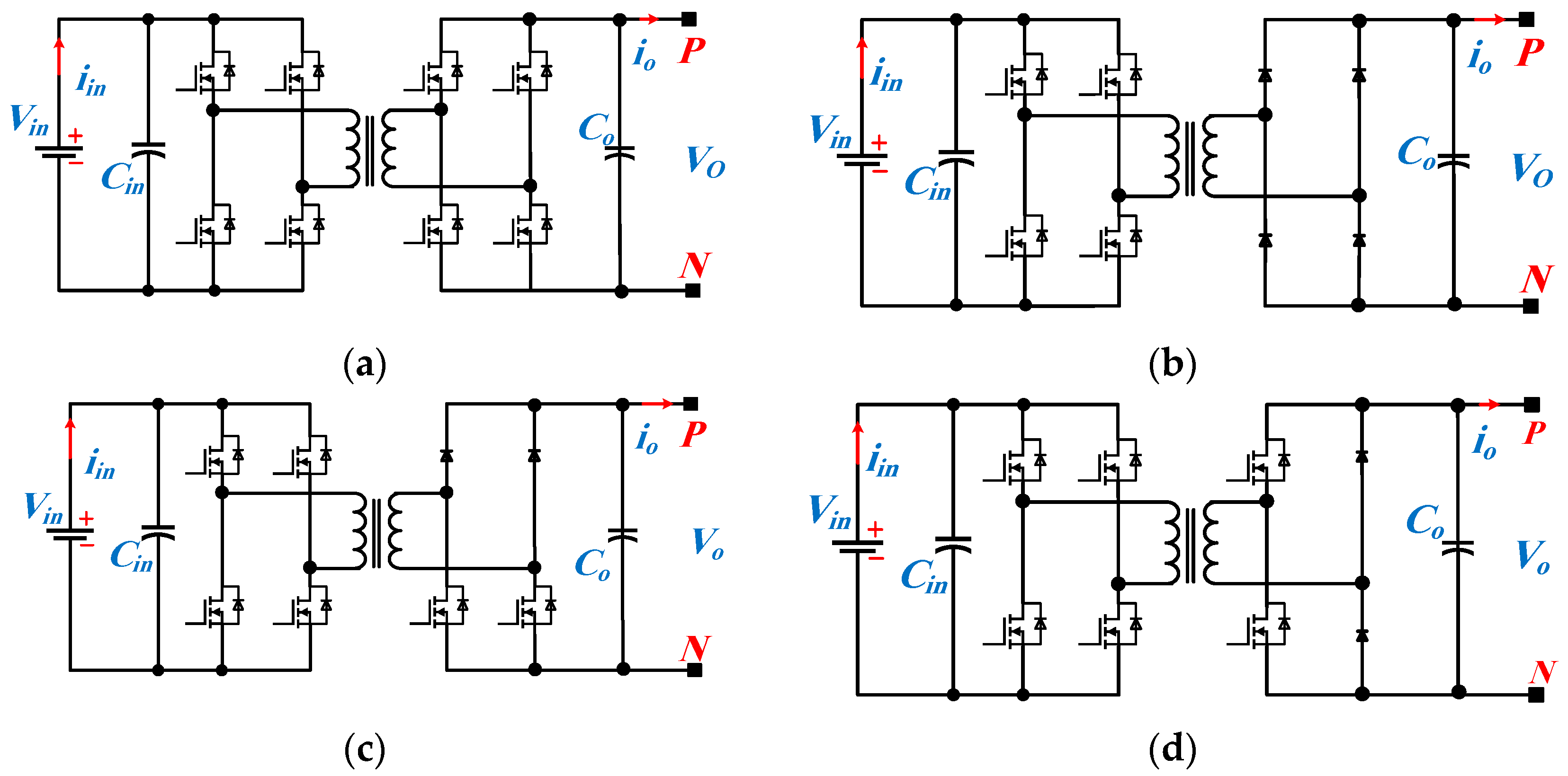
Several MMI topologies employ the DAB converter as an SM in large-scale grid-connected PV systems, as presented in [92,93] to provide increased power quality, zero-voltage switching (ZVS) operation, and bidirectional power-flow capabilities. The main DAB converter, shown in Figure 17a, inherently includes HFT, so it can offer both galvanic isolations and increased output voltage [94]. The input/output side of the DAB SMs can be connected in series or in parallel. The four possible connection designs are input parallel output series (IPOS), input parallel output parallel (IPOP), input series output series (ISOP), and input series output parallel (ISOP). In high-power applications, the first design of connection (IPOS) is desired because the electric stress across switches is dispersed among SM inverters, resulting in improved efficiency and lesser power losses [95,96,97,98,99].
The work in [91] proposed a topology that integrates PV modules and grid-connected converters using flyback converter concepts. This topology allows for a simple controller implementation and a low-cost design. Despite the benefits offered by the fly-back converters, it has a high leakage inductance and discontinuous current nature at the input and output sides, which will limit the conversion efficiency [100]. A single active bridge (SAB) submodule, shown in Figure 17b, was proposed in [101] to reduce the number of power switches and provide unidirectional power flow. Although the SAB is a simple and reliable converter that uses a four-diode rectifier secondary side, the lack of secondary-side control increases the harmonic content in the output current and reduces the converter’s reliability [22]. Thus, Semi-DABs were developed to allow independently control of the secondary side with only two active switches as shown in Figure 17c [102]. As an advantage, this topology increases ZVS range with fewer active switches. In [103], the Forward-DAB (F-DAB), shown in Figure 17d, has been used in a cascaded multilevel structure to offer unidirectional power flow in a PV system. This topology enables high power-density operation and reduces the converter’s total size, as well as the device count. Another advantage of this suggested topology is that the F-DAB permits the use of the same control approach as the DAB converter. Additionally, F-DAB has the most compact circuit among the unidirectional DAB topologies [22]. Yet, the primary drawback of unidirectional MMI topologies is that they are not suitable for STATCOM operation at night. This is because these topologies allow for regulated power flow in one direction (from PV to load) and the control is lost if power flow is reversed [104].

4. Control Strategies of Grid-Tied Inverters
The main purpose of the PV systems controllers is to control the PV converters, so the DC energy generated by PV modules is converted to AC power and injected into the AC electrical grid. The controller ensures that the energy harvested from the DC side is maximized, and that the power delivered at the output side is improved in terms of power quality and the grid’s standards. This desired operation is dependent on developing a rapid and accurate control system. Therefore, the control process is not less important than the electronic power topology itself. The control system of the grid-connected inverters can be classified into two main parts. The first is the MPPT controller, on the input side, which deals mainly with the PV modules. This controller is responsible for extracting maximum power from the PV modules and ensuring that they are operating according to the specifications determined by their manufacturer. The second part is a grid-side inverter controller, which regulates the power transfer process and ensures that output voltages and currents are within the acceptable ranges set by the grid’s codes. The next subsections will discuss the most common control schemes for PV applications and discuss their suitability for the large-scale PV plants.
4.1. Maximum Power Point Tracking Control
The MPPT controller keeps the operation of the PV modules at the maximum power point (MPP) which is the highest operation point on the power-voltage (P–V) curve, allowing for the maximum amount of PV module power to be generated as shown in Figure 18. To obtain this maximum power from the PV module, the PV module current and voltages should be kept at point B on the current-voltage (I–V) curve so the power is kept at point D on the P–V curve.
The PV curves shown in Figure 18 change with the varying solar irradiance and temperature [105]. Thus, the MPPT controller will be responsible for changing the values of the PV module’s voltage and current continuously to ensure that the maximum power is always obtained. The MPPT does that by controlling the associated converter connected to the PV modules by changing its duty cycle ratio [106]. During partial shading of the PV modules, the I–V and P–V curves will have several local maxima points, as shown in Figure 19. Therefore, the MPPT controllers should avoid settling at the local maxima points instead of the global maximum, which puts an additional burden on the operation [105].
Several MPPT controllers have been presented in the literature where their performances vary in terms of tracking speed, efficiency, and complexity. The most common MPPT controllers are perturbation and observation (PandO) [107], incremental conductance (INC) [108], hill climbing (HC) [109], and open-circuit voltage (OCV) [105]. These control techniques use similar concepts of changing the operational points by varying the PV module’s current and voltage slightly, record the change in the output power and then assess if the MPP has been reached or not. These controllers can be applied to any sort of PV module and the measurement of the sun irradiance and PV module’s temperature is not necessary [110]. Because the P–V curve has several peak points during partial shading conditions, both controllers fail to find the maximum peaks in order to acquire the highest MPP and they usually settle at a local MPP resulting in up to 70% power loss [111]. Accordingly, these controllers are not suitable for the MMIs in the context of large-scale PV systems and may be limited to low-power residential applications.
New advanced MPPT control strategies have been developed later to deal with the efficiency degradation and sluggish tracking speed under partial shading conditions [112]. These strategies aim to solve the partial shading problems, deal with minor steady-state oscillations, reduce the disturbance around MPP, provide flexibility when operating with nonlinear loads, and provide a high degree of accuracy [113]. These strategies include genetic algorithms (GA) [114], fuzzy logic (FL) [115], particle swarm optimization (PSO) [116], and artificial bee colonies (ABC) [117]. In PSO algorithms, once the operation approaches the MPP and a particular criterion is met, the PSO algorithm instantly stops perturbing the control parameter to obtain better performance at a steady state [118,119]. The ABC MPPT algorithm identifies the P–V characteristic in advance and selects the best voltage utilizing data from the PV module. The MPPT technique is used to generate the voltage reference for the outer Proportional–Integral (PI) control loop, which then serves as the current reference for the inner predictive current control loop [117]. The ABC algorithm provides several advantages, such as having outstanding tracking performance with high efficiency, increasing simplicity and flexibility, and achieving a quick response due to the use of a double-loop control system with an inner current controller [120]. The ABC controller is considered superior to the PandO method as it can achieve high efficiency under constant and variable weather conditions [117]. Thus, the ABC MPPT algorithm is suitable for implementation in large-scale PV systems.
Hybrid MPPT controllers have been developed to handle the problems that both traditional and advanced MPPT methods have. The hybrid MPPT controllers combine two MPPT approaches in the same application, and they have the potential to increase overall efficiency while also performing well in partial shade conditions [121]. Furthermore, hybrid controllers can outperform individual algorithms when it comes to obtaining better tracking responses [24]. In [122], a hybrid MPPT controller was presented that combines the PandO and PSO methods in partial shading conditions. The first stage employs PSO for MPPT, while the second stage uses the classic PandO method. The hybrid MPPT controller is more efficient and improves convergence time to the MPPT when compared to applying each approach separately. In [123], another hybrid MPPT controller was proposed that integrates an artificial neural network (ANN) technique with the PandO algorithm to track the MPP. The ANN MPPT is employed as a classifier to expect which part of the PV curve will have a new shading pattern. The suggested method enables fast tracking of the global MPP under different conditions, including variable shading patterns, fast and changeable solar radiation, and gradient temperature distribution. The hybrid MPPT controller is the best candidate for large-scale PV systems, which will need more than one level of control when the number of PV modules is increased [121,122,123]. Thus, it can combine module- and systems-level algorithms when MPPT controllers are needed at the PV module to reduce shading effects, as well as the system’s level, to harvest the maximum power from the overall system.
4.2. Grid-Side Inverter Control
The grid-side inverter control technique is crucial for guaranteeing efficient operation of the MMIs in PV grid-connected systems. The most wide-spread control methods in MMIs are instantaneous active and reactive power and synchronous reference frame methods [124,125]. These methods extract the fundamental and harmonic quantities by converting current- and voltage-measured waveforms from the stationary ABC frame to another stationary reference frame (PQ control), as shown in Figure 20, or to a synchronously rotating reference (DQ) frame [124]. MMI controllers based on PQ control were investigated in [126,127] and have been shown to have limits when the input supply voltages have imbalances and/or distortions.
In the CHB MMI topology, active and reactive power regulation is coordinated using double-loop DQ control based on discrete Fourier transforms (DFT) and phase-locked loop (PLL) control techniques [128]. In this method, the PI controller regulates the DC voltage of each inverter module to track the reference.
In [129], a control strategy that allows each DC link voltage in the CHB MMI to be controlled independently with reduced stresses on the CHB cells was discussed. Using this method, a PI controller was designed to adjust the equivalent duty cycle of each H-bridge inverter to balance the DC- link voltages. The suggested PI control enables the appropriate levels of power to be applied to each cell to guarantee that they are always balanced with the connected loads.
The work in [130] suggested a zero-sequence voltage compensation control method for the CHB MMI inverter. The control method can be associated with a suitable zero-sequence voltage that is computed and compensated system based on the actual number of modules. This assures that all modules in a three-phase inverter can transmit the same active powers, regardless the number of modules in each phase or the operation’s power factor. The problems of existing zero-sequence approaches for CHB under severe power imbalance have been described in [50] and then a simpler optimal zero-sequence method has been proposed. In [131], a model-predictive control, based on zero-sequence injection techniques, was described for a conventional CHB inverter.
A further control approach, based on a novel integrated fuzzy logic FL controller, was designed for CHB MMIs [132]. The work presented the implementation of a fully FL controller with no pulse–width–modulation (PWM), switching-angle generator or PI controller and an H-bridge power-sharing algorithm.
The work in [133] presented a proportional resonant (PR) controller for MMCs in a grid-tied PV interface during partial shade conditions, as shown in Figure 21. The PR controller is designed to have a superior frequency response and better harmonic performance than the PI controllers at the grid’s frequency band. For the proper operation of the MCC, the unregulated supply from PV source is managed by the DC link controller. However, the controller fails to maintain a constant SM voltage, the MPPT problem is not addressed, and the MMC’s internal power flow regulation is not described in this study.
The work in [80] describes a control system for three-phase MMI in large scale PV plants. The PV strings are connected to the MMC’s SMs through a DC–DC converter to take advantage of the benefits of independent MPPT, modularity, and scalability. The phase voltages of the MMI are controlled using the feedforward compensation control approach based on zero-sequence voltage injection to generate balanced three-phase output power. The proposed strategy introduces more grid interactions by distorting the terminal voltage. It is limited by each cell’s maximum possible DC voltage, which restricts operation in cases of extreme power imbalance. Furthermore, it can only compensate the leg power unbalances but cannot fix the power unbalances between the different arms.
In the medium-voltage scale, the work in [84] provides a power-mismatch elimination-control technique for MMC in PV applications. Despite the PV arrays’ unbalanced output, the technique maintains a balanced grid current, and both leg- and arm-mismatch problems have been solved by the proposed control approach. However, the proposed control strategy’s performance under SM unbalanced scenarios has not been evaluated.
For direct integration of PV arrays with the MMIs, a new control technique was presented in [81]. The proposed control can deal with the MPPT’s multi-peak optimization challenge when the PV panels become entirely shaded. The control was developed using a redundant SM of the MMC that was installed in each arm to compensate for voltage variations in distributed PV arrays. However, the proposed controller needs improvement to handle the unbalances and the harmonics that may appear in weak grids.
4.3. Control Strategy under Imbalanced Conditions
The performance of the PV generation systems is dependent on solar energy, which varies drastically with the weather conditions. The employed power converters can provide steady operation under balanced settings since all PV strings have the same irradiance and ambient weather circumstances. If different irradiances are applied to the PV modules or strings, an uneven outflow of power will occur, which may lead to imbalances in the converter’s voltages and currents. The extreme current stress caused by the imbalances and their associated effects on the power grid were studied by Guo et al. [134]. The authors have presented a new current-limited control approach for the flexible regulation of active and reactive power control. Moreover, this control approach is proved to manage grids current under grid failure and minimize the extreme current stress in such cases.
The power difference between the cells in the same phase leg of an MMI (inter-bridge power unbalance) and the power imbalance between different phases (inter-phase power unbalance) were studied in a three-phase PV system employing the MLI CHB topology [22]. A control approach was proposed to eliminate the problem of inter-bridge power imbalance by employing an appropriate modulation strategy [135]. As it uses an ideal number of switching operations to provide a number of power flow paths between converter cells, the suggested modulation technique not only reduces the loss balance but also enhances efficiency. The work in [136] have discussed and examined the PV module that generates the lowest amount of power as the primary operating point for all PV modules in order to balance the power between converter cells as much as possible. Although the proposed solution solves the inter power imbalance problem, it has a negative impact on converter efficiency since it does not benefit from the advantages of distributed MPPT.
Zero-sequence current (ZSC) and zero-sequence voltage (ZSV) techniques for injecting compensating components into delta- and star-connected CHB converters were developed to address power imbalance between phases in [61]. ZSC injection methods were developed to improve power balancing capabilities in a delta-connected CHB converter [131]. Additionally, it is capable of providing superior phase voltage balancing features than the ZSV approach. However, as the power imbalance grows, more ZSC must be injected to balance the line current, hence limiting the maximum current that can flow through each converter cell. Furthermore, it demands a controller for both inter-bridge and inter-phase operations that increase the complexity of the control system [45].
For delta-connected CHB MMIs, several ZVS injection control strategies have been presented in order to provide high quality power under severe power imbalance scenarios [22,50,61,131]. A simple method of injecting third harmonic square wave in the ZSV control schemes of CHB MMI under balanced and unbalanced grid situations has been presented in [61].
An optimal zero sequence injection (OZSI) has been investigated to address the interphase power imbalance using CHB PV converters [50]. The proposed OZSI method has a restricted number of negative sequence currents, but the convergence rate of its iterations is very quick. Moreover, it saves time by reducing the number of required calculations. However, this comes at the expense of more negative-sequence grid currents. Also, the available DC-link voltage in each phase of a star-connected CHB converter restricts the ability of power-balancing when compared with alternative ZSV injection methods [22]. The power-balancing capabilities of the OZSI method cannot be more than 20% of the power imbalance [62].
Comparing with the CHB MMI, MMC-based topologies face the same challenges of unbalanced distributed power. Thus, it should be noted that the control-balancing techniques utilized in the CHB converter can also be employed by the MMC converter with some modifications [80]. However, the MMC faces an extra imbalance problem, which occurs internally between its arms [137]. The authors investigated the possibility of controlling the power flow inside an MMC converter with internally generated currents in the arms and then injecting a three-phase balanced current into the grid to compensate for power imbalances that are induced by the different PV power sources. The technique develops reference-arm currents by considering the amount of energy stored inside each capacitor. Then, the leg currents are regulated individually, to keep the converter balanced and supply equal current to the grid with low harmonic characteristics, as shown in Figure 22 [137].
A control strategy for an MMC should integrate multi-hierarchy control with arm-current control, with the aim of balancing the MMC’s arms. With the multi-hierarchy control in [138], three voltage controllers in stationary ABC coordinates simply change active power distribution among the three legs to provide symmetrical AC-side current references and irregularly distributed DC-current references. The regulation of an arm current to track its reference is handled by a proportional regulator with a feed-forward steady-state duty cycle.
5. The Future of Large-Scale PV Systems
The EU countries are committed to reducing their dependency on fossil fuels and increasing the use of renewable energy sources, such that greenhouse gas emissions should be reduced by 80–95% in their 30-year plan, as compared with the year 1990. This plan means that the EU’s energy and transportation sectors will be completely decarbonized before 2050 [139]. This ambitious goal will lead to a drastic change in the shape of energy-generation systems. The European Photovoltaic Industry Association (EPIA) predicts three scenarios for PV systems’ penetration into the electrical energy sector in the future [140]. In the first baseline scenario, PV electricity will supply 10% of the total electrical energy demand by 2030. In the second accelerated scenario, the PV electricity may be able to supply 15% of the total electricity demand by 2030. The third paradigm-shift scenario hopes for coverage around 25% of the electrical energy demand by 2030 [141]. However, which scenario will be achieved in reality will depend on whether large-scale PV systems will be a key player in the future of the energy-generation sector.
The EPIA reports confirm that the integration of large-scale PV system in electrical grids is technically feasible and can satisfy security of supply even under very drastic weather and loadings, and the reliability of these energy generation systems can be guaranteed with proper action and investment [139,140,141]. Large-scale PV systems can support electrical grids in terms of reducing reactive power, ensuring fault-ride-through capabilities, providing support to the grid’s voltage and reducing the fault current contribution [142].
From the technical point of view, MMIs have an increased in popularity in grid-connected and commercial applications over time, due to their many advantages. For example, MMIs are capable of high-power generation and conversion and can also reduce low-harmonic injection into the grid to comply with utility grid regulations [22,27].
New MMI topologies are expected to emerge in the industry to help with the increased penetration of PV systems in electrical networks [143]. These MMI topologies are required to reduce the total size and weight of PV systems, providing high efficiency and power density, better control, and power-flow flexibility, and provide grids with support features, such as dynamic voltage support, fault ride-through capabilities, and compliance with safety rules through galvanic isolation [27,88]. On the other hand, the innovative topologies currently available are mostly experimental prototypes with low capacities, and hence MMIs with power ratings in the megawatt range should drive these topologies to the industrial market for solar PV systems.
To ease the penetration of large-scale PV systems, reducing the switch count of the MMI topologies is necessary, in the future, to simplify control systems, reduce operational cost, and reducing their environmental footprint [144]. MMIs based on CHBs are suitable candidates for such integration, since they offer increased power quality as well as the ability to handle higher power and voltage ratings [22,61].
A wider range of intelligent algorithms and robust controllers should be investigated and tested to improve the performance efficiency of PV systems and ease their penetration in industrial MV networks [119,120,121,122,123,124,125,126,127,128,129,130,131,132,133,134,135,136,137,138]. For example, traditional controllers (e.g., PI and PR controllers) are commonly used to maintain DC-link voltage and manage the MPPT in MMIs. Yet, these controllers have significant limitations when implemented in high-power systems, as they lack the required accuracy [44,133,145]. Moreover, the efficiency of MPPT control is influenced by several factors, such as a PV system’s nonlinear structure, shading conditions, and variations in ambient conditions. Most control developers ignore these changes, which has resulted in system failure in several situations [107,144]. MPPT-controller design is a crucial challenge for the penetration of large-scale PV systems in MV networks and requires further consideration regarding the maintenance of stability, especially with increasing output power and the necessity of multi-layer hierarchal MPPT control systems [54,62]. These control systems are required to be coordinated with the output grid-side controllers and to address power imbalance problems, especially during extreme or varying weather conditions. Therefore, studies which emphasize testing and experimentation are required to develop the necessary control strategies for these scenarios.
6. Conclusions
This paper presented a comprehensive review of multilevel inverters that can be employed in high-power PV applications. Classification was based on inverter structures, and for each class, we have discussed the different advantages and limitations to help identify the suitability of each power converter topology for grid-tied PV systems at large scales. According to this review, both the CHB and MMC families are the most suitable topologies for this application, as they offer modularity, reliability, grid support, and high power density. However, more improvements are required for the CHB- and MMC-based topologies to guarantee the desired galvanic isolation, provide better SMs balancing, and ensure distributed MPPT capabilities.
On the other hand, modular structures based on SMPS circuits are promising for integrating PV plants into grids because they combine the benefits of modularity, galvanic isolation, and bidirectional power flow to meet required voltages and improve overall efficiency.
Multilevel DAB with IPOS structures are also a potential solution for large-scale PV applications due to their capability to increase overall power and operate with high power density. In addition, several unidirectional power flow submodule topologies, such as Semi-DABs and Forward-DABs, are proposed as solutions to increasing power density with fewer components.
According to this review, the optimum method of MPPT topology for PV application should combine the merits of rigorous stability, fast calculation, and accuracy. Although PandO and incremental-conductance techniques are frequently used in the present PV systems due to their simple hardware implementation, they pose a considerable amount of steady-state oscillations and lack the required accuracy for large-scale application. Instead, advanced MPPT control strategies and hybrid MPPT controllers should be employed, due to their ability to provide better tracking performance, faster operation, and the ability to develop multi-layer MPPT control systems wherein the PV modules are controlled at both the modular and system levels. The complexity of this control design will be increased with increased output voltage and power because the number of PV modules and voltage levels also increase. Several grid-side control schemes have been reviewed and discussed in this paper. Presently, the PQ method is the most common control technique on the grid-side of the MMI because of its simplicity. However, the PQ method will need further improvement to integrate it within multi-layer MPPT algorithms at the input PV side. These controllers should also consider the unbalanced conditions of both the input-PV and output-grid sides. Thus, a variety of balancing methods for CHB and MMC topologies have been explored and discussed in this paper, from which we conclude that ZSC and ZSV control techniques offer impressive performance in unbalanced PV power generation.
Finally, the challenges of, recommendations for, and future predictions for modular PV inverters in MV applications have been addressed to promote better awareness of the importance of developing efficient MMI grid-connected PV systems, which are cost-effective and can be commercially applicable soon.
Author Contributions
Conceptualization, S.A. and A.D.; methodology, S.A. and A.D.; software, S.A. and A.D; validation, A.D. and S.A.; formal analysis, S.A. and A.D.; investigation, S.A. and A.D.; resources, S.A. and A.D; data curation, A.D.; writing—original draft preparation, S.A.; writing—review and editing, A.D.; visualization, S.A. and A.D.; supervision, A.D.; project administration, A.D.; funding acquisition, S.A. and A.D. Both authors have read and agreed to the published version of the manuscript.
Funding
This research received no external funding.
Institutional Review Board Statement
Not applicable.
Informed Consent Statement
Not applicable.
Acknowledgments
Saud Alotaibi gratefully acknowledges Shaqra University for having provided full financial support to make this research possible at Lancaster University.
Conflicts of Interest
The authors declare no conflict of interest.
References
- Kroposki, B.; Johnson, B.; Zhang, Y.; Gevorgian, V.; Denholm, P.; Hodge, B.M.; Hannegan, B. Achieving a 100% Renewable Grid: Operating Electric Power Systems with Extremely High Levels of Variable Renewable Energy. IEEE Power Energy Mag. 2017, 15, 61–73. [Google Scholar] [CrossRef]
- Solar Power Europe. Solar Market Report and Membership Directory; Solar Power Europe: Brussels, Belgium, 2016; Volume 1. [Google Scholar]
- International Renewable Energy Agency. Future of Solar Photovoltaic: Deployment, Investment, Technology, Grid Integration and Socio-Economic Aspects; International Renewable Energy Agency: Abu Dhabi, United Arab Emirates, 2020; Available online: https://www.irena.org/publications/2019/Nov/Future-of-Solar-Photovoltaic (accessed on 5 August 2021).
- REN21. Renewables 2020 Global Status Report; REN21: Paris, France, 2020; ISBN 978-3-948393-00-7. [Google Scholar]
- Energy, I.; Iea, A. IEA. Renewable Energy Market Update; IEA: Paris, France, 2020; Available online: https://www.iea.org/reports/renewable-energy-market-update (accessed on 12 August 2021).
- Karimi, M.; Mokhlis, H.; Naidu, K.; Uddin, S.; Bakar, A.H.A. Photovoltaic penetration issues and impacts in distribution network—A review. Renew. Sustain. Energy Rev. 2016, 53, 594–605. [Google Scholar] [CrossRef]
- Hasan, R.; Mekhilef, S.; Seyedmahmoudian, M.; Horan, B. Grid-connected isolated PV microinverters: A review. Renew. Sustain. Energy Rev. 2017, 67, 1065–1080. [Google Scholar] [CrossRef]
- Dogga, R.; Pathak, M.K. Recent trends in solar PV inverter topologies. Sol. Energy 2019, 183, 57–73. [Google Scholar] [CrossRef]
- Kent, R. Renewables 2020 Analysis and forecast to 2025. Plast. Eng. 2018, 74, 56–57. [Google Scholar] [CrossRef]
- Darwish, A.; Elserougi, A.; Abdel-Khalik, A.S.; Ahmed, S.; Massoud, A.; Holliday, D.; Williams, B.W. A single-stage three-phase DC/AC inverter based on Cuk converter for PV application. In Proceedings of the 2013 7th IEEE GCC Conference and Exhibition (GCC), Doha, Qatar, 17–20 November 2013; pp. 384–389. [Google Scholar]
- Mansouri, N.; Lashab, A.; Sera, D.; Guerrero, J.M.; Cherif, A. Large photovoltaic power plants integration: A review of challenges and solutions. Energies 2019, 12, 3798. [Google Scholar] [CrossRef] [Green Version]
- Jana, J.; Saha, H.; Das Bhattacharya, K. A review of inverter topologies for single-phase grid-connected photovoltaic systems. Renew. Sustain. Energy Rev. 2017, 72, 1256–1270. [Google Scholar] [CrossRef]
- Azmi, S.A.; Adam, G.P.; Ahmed, K.H.; Finney, S.J.; Williams, B.W. Grid interfacing of multimegawatt photovoltaic inverters. IEEE Trans. Power Electron. 2013, 28, 2770–2784. [Google Scholar] [CrossRef]
- Islam, M.R.; Guo, Y.; Zhu, J. A high-frequency link multilevel cascaded medium-voltage converter for direct grid integration of renewable energy systems. IEEE Trans. Power Electron. 2014, 29, 4167–4182. [Google Scholar] [CrossRef]
- Choi, H.; Ciobotaru, M.; Jang, M.; Agelidis, V.G. Performance of Medium-Voltage DC-Bus PV System. IEEE Trans. Sustain. Energy 2015, 6, 464–473. [Google Scholar] [CrossRef]
- Rabiul Islam, M.; Mahfuz-Ur-Rahman, A.M.; Muttaqi, K.M.; Sutanto, D. State-of-The-Art of the Medium-Voltage Power Converter Technologies for Grid Integration of Solar Photovoltaic Power Plants. IEEE Trans. Energy Convers. 2019, 34, 372–384. [Google Scholar] [CrossRef]
- ASEABrown Boveri (ABB). ABB Solar Inverters for Photovoltaic Systems; ASEABrown Boveri (ABB): Zürich, Switzerland, 2019. [Google Scholar]
- Darwish, A. Current Source DC-DC and DC-AC Converters with Continuous Energy Flow. Ph.D. Thesis, University of Strathclyde, Glasgow, Scotland, 2015. [Google Scholar]
- Mechouma, R.; Azoui, B.; Chaabane, M. Three-phase grid connected inverter for photovoltaic systems, a review. In Proceedings of the 2012 First International Conference on Renewable Energies and Vehicular Technology, Nabeul, Tunisia, 26–28 March 2012; pp. 37–42. [Google Scholar] [CrossRef]
- Huang, X.; Liu, Z.; Li, Q.; Lee, F.C. Evaluation and application of 600 v GaN HEMT in cascode structure. IEEE Trans. Power Electron. 2014, 29, 2453–2461. [Google Scholar] [CrossRef]
- Rashid, M.H.; Hui, S.R.; Chung, H.S. Resonant and Soft-Switching Converters. In Power Electronics Handbook; Butterworth-Heinemann: Oxford, UK, 2018; ISBN 9780128114070. [Google Scholar]
- Elsanabary, A.I.; Konstantinou, G.; Mekhilef, S.; Townsend, C.D.; Seyedmahmoudian, M.; Stojcevski, A. Medium Voltage Large-Scale Grid-Connected Photovoltaic Systems Using Cascaded H-Bridge and Modular Multilevel Converters: A Review. IEEE Access 2020, 8, 223686–223699. [Google Scholar] [CrossRef]
- Kolantla, D.; Mikkili, S.; Pendem, S.R.; Desai, A.A. Critical review on various inverter topologies for pv system architectures. IET Renew. Power Gener. 2020, 14, 3418–3438. [Google Scholar] [CrossRef]
- Bughneda, A.; Salem, M.; Richelli, A.; Ishak, D.; Alatai, S. Review of multilevel inverters for PV energy system applications. Energies 2021, 14, 1585. [Google Scholar] [CrossRef]
- Zhang, X.; Zhao, T.; Mao, W.; Tan, D.; Chang, L. Multilevel inverters for grid-connected photovoltaic applications: Examining emerging trends. IEEE Power Electron. Mag. 2018, 5, 32–41. [Google Scholar] [CrossRef]
- Darwish, A.; Massoud, A.; Holliday, D.; Ahmed, S.; Williams, B. Generation, performance evaluation and control design of single-phase differential-mode buck–boost current-source inverters. IET Renew. Power Gener. 2016, 10, 916–927. [Google Scholar] [CrossRef] [Green Version]
- Darwish, A.; Elgenedy, M.A. Current-source modular medium-voltage grid-connected system with high-frequency isolation for photovoltaic applications. IEEE Trans. Energy Convers. 2019, 34, 255–266. [Google Scholar] [CrossRef] [Green Version]
- Islam, M.T.; Islam, M.R.; Rahman, M.S.; Rahman, M.F.; Rahman, M.A. A new medium voltage modular multilevel inverter with advanced carrier-based pulse width modulation for solar photovoltaic systems. In Proceedings of the 2019 International Conference on Sustainable Technologies for Industry 4.0 (STI), Dhaka, Bangladesh, 24–25 December 2019; pp. 24–25. [Google Scholar] [CrossRef]
- Rojas, C.A.; Kouro, S.; Perez, M.A.; Echeverria, J. DC-DC MMC for HVdc Grid Interface of Utility-Scale Photovoltaic Conversion Systems. IEEE Trans. Ind. Electron. 2018, 65, 352–362. [Google Scholar] [CrossRef]
- Darwish, A.; Holliday, D.; Finney, S. Operation and control design of an input series–input-parallel–output-series conversion scheme for offshore DC wind systems. IET Power Electronics. 2017, 10, 2092–2103. [Google Scholar] [CrossRef] [Green Version]
- Darwish, A. Efficient modular multilevel converter based on active-forced commutated hybrid packed u-cells for HV networks. In Proceedings of the 15th IET International Conference on AC and DC Power Transmission (ACDC 2019), Coventry, UK, 5–7 February 2019. [Google Scholar]
- Rodríguez, J.; Bernet, S.; Wu, B.; Pontt, J.O.; Kouro, S. Multilevel voltage-source-converter topologies for industrial medium-voltage drives. IEEE Trans. Ind. Electron. 2007, 54, 2930–2945. [Google Scholar] [CrossRef]
- Kouro, S.; Malinowski, M.; Gopakumar, K.; Pou, J.; Franquelo, L.G.; Wu, B.; Rodriguez, J.; Perez, M.A.; Leon, J.I. Recent advances and industrial applications of multilevel converters. IEEE Trans. Ind. Electron. 2010, 57, 2553–2580. [Google Scholar] [CrossRef]
- Darwish, A.; Massoud, A.; Holliday, D.; Ahmed, S.; Williams, B. Single-stage Three-phase Differential-mode Buck-Boost Inverters with Continuous Input Current for PV Applications. IEEE Trans. Power Electron. 2016, 31, 8218–8236. [Google Scholar] [CrossRef] [Green Version]
- Chen, A.; He, X. Research on Hybrid-Clamped Multilevel-Inverter Topologies. IEEE Trans. Ind. Electron. 2006, 53, 1898–1907. [Google Scholar] [CrossRef]
- Palomino, J.D.G. Design and Evaluation of a Single Phase 5 Level Full Bridge Neutral Point Clamped Multi Level Converter. Ph.D. Thesis, University of Sheffield, Sheffield, UK, 2017. [Google Scholar]
- Rodriguez, J.; Member, S.; Bernet, S.; Steimer, P.K.; Lizama, I.E. A Survey on Neutral-Point-Clamped Inverters. IEEE Trans. Ind. Electron. 2010, 57, 2219–2230. [Google Scholar] [CrossRef]
- Wang, H.; Kou, L.; Liu, Y.; Sen, P.C. A Seven-Switch Five-Level Active-Neutral-Point-Clamped Converter and Its Optimal Modulation Strategy. IEEE Trans. Power Electron. 2017, 32, 5146–5161. [Google Scholar] [CrossRef]
- Teymour, H.R.; Sutanto, D.; Muttaqi, K.M.; Ciufo, P. Solar PV and battery storage integration using a new configuration of a three-level NPC inverter with advanced control strategy. IEEE Trans. Energy Convers. 2014, 29, 354–365. [Google Scholar] [CrossRef]
- Mahela, O.P.; Shaik, A.G. Comprehensive overview of grid interfaced solar photovoltaic systems. Renew. Sustain. Energy Rev. 2017, 68, 316–332. [Google Scholar] [CrossRef]
- Kouro, S.; Leon, J.I.; Vinnikov, D.; Franquelo, L.G. Grid-connected photovoltaic systems: An overview of recent research and emerging PV converter technology. IEEE Ind. Electron. Mag. 2015, 9, 47–61. [Google Scholar] [CrossRef]
- Gao, M.; Chen, M.; Zhang, C.; Qian, Z. Analysis and implementation of an improved flyback inverter for photovoltaic AC module applications. IEEE Trans. Power Electron. 2014, 29, 3428–3444. [Google Scholar] [CrossRef]
- Colak, I.; Kabalci, E.; Bayindir, R. Review of multilevel voltage source inverter topologies and control schemes. Energy Convers. Manag. 2011, 52, 1114–1128. [Google Scholar] [CrossRef]
- Barghi Latran, M.; Teke, A. Investigation of multilevel multifunctional grid connected inverter topologies and control strategies used in photovoltaic systems. Renew. Sustain. Energy Rev. 2015, 42, 361–376. [Google Scholar] [CrossRef]
- Le, Q.A.; Lee, D.C. A Novel Six-Level Inverter Topology for Medium-Voltage Applications. IEEE Trans. Ind. Electron. 2016, 63, 7195–7203. [Google Scholar] [CrossRef]
- Franquelo, L.G.; Rodriguez, J.; Leon, J.I.; Kouro, S.; Portillo, R.; Prats, M.A.M. The age of multilevel converters arrives. IEEE Ind. Electron. Mag. 2008, 2, 28–39. [Google Scholar] [CrossRef] [Green Version]
- Noman, A.M.; Addoweesh, K.E.; Alabduljabbar, A.A.; Alolah, A.I. Cascaded H-bridge MLI and three-phase cascaded VSI topologies for grid-connected PV systems with distributed MPPT. Int. J. Photoenergy 2019, 2019, 7642919. [Google Scholar] [CrossRef]
- Farivar, G.; Hredzak, B.; Agelidis, V.G. A DC-Side Sensorless Cascaded H-Bridge Multilevel Converter-Based Photovoltaic System. IEEE Trans. Ind. Electron. 2016, 63, 4233–4241. [Google Scholar] [CrossRef]
- Briz, F.; López, M.; Rodríguez, A.; Arias, M. Modular Power Electronic Transformers. IEEE Ind. Electron. Mag. 2016, 6–19. [Google Scholar] [CrossRef]
- Yu, Y.; Konstantinou, G.; Hredzak, B.; Agelidis, V.G. Power Balance Optimization of Cascaded H-Bridge Multilevel Converters for Large-Scale Photovoltaic Integration. IEEE Trans. Power Electron. 2016, 31, 1108–1120. [Google Scholar] [CrossRef] [Green Version]
- Yang, Z.; Sun, J.; Tang, Y.; Huang, M.; Zha, X. An Integrated Dual Voltage Loop Control for Capacitance Reduction in CHB-Based Regenerative Motor Drive Systems. IEEE Trans. Ind. Electron. 2019, 66, 3369–3379. [Google Scholar] [CrossRef]
- Xiao, B.; Hang, L.; Mei, J.; Riley, C.; Tolbert, L.M.; Ozpineci, B. Modular Cascaded H-Bridge Multilevel PV Inverter with Distributed MPPT for Grid-Connected Applications. IEEE Trans. Ind. Appl. 2015, 51, 1722–1731. [Google Scholar] [CrossRef]
- Xiao, B.; Hang, L.; Tolbert, L.M. Control of three-phase cascaded voltage source inverter for grid-connected photovoltaic systems. In Proceedings of the 2013 Twenty-Eighth Annual IEEE Applied Power Electronics Conference and Exposition (APEC), Long Beach, CA, USA, 17–21 March 2013; pp. 291–296. [Google Scholar] [CrossRef]
- Wang, C.; Zhang, K.; Xiong, J.; Xue, Y.; Liu, W. A Coordinated Compensation Strategy for Module Mismatch of CHB-PV Systems Based on Improved LS-PWM and Reactive Power Injection. IEEE Trans. Ind. Electron. 2019, 66, 2825–2836. [Google Scholar] [CrossRef]
- Inverters, S.C.M.; Lehman, B. An intelligent-based fault-tolerant system for solar-fed cascaded multilevel inverters. IEEE Trans. Energy Convers. 2018, 33, 1047–1057. [Google Scholar]
- Kartick, J.C.; Sujit, B.K.; Suparna, K.C. Dual reference phase shifted pulse width modulation technique for a N-level inverter based grid connected solar photovoltaic system. IET Renew. Power Gener. 2016, 10, 928–935. [Google Scholar] [CrossRef]
- Shi, Y.; Li, R.; Xue, Y.; Li, H. High-frequency-link-based grid-tied PV system with small DC-link capacitor and low-frequency ripple-free maximum power point tracking. IEEE Trans. Power Electron. 2016, 31, 328–339. [Google Scholar] [CrossRef]
- Liu, L.; Li, H.; Xue, Y.; Liu, W. Decoupled active and reactive power control for large-scale grid-connected photovoltaic systems using cascaded modular multilevel converters. IEEE Trans. Power Electron. 2015, 30, 176–187. [Google Scholar] [CrossRef]
- Amaral, F.V.; Parreiras, T.M.; Lobato, G.C.; Machado, A.A.P.; Pires, I.A.; De Jesus Cardoso Filho, B. Operation of a Grid-Tied Cascaded Multilevel Converter Based on a Forward Solid-State Transformer under Unbalanced PV Power Generation. IEEE Trans. Ind. Appl. 2018, 54, 5493–5503. [Google Scholar] [CrossRef]
- Essakiappan, S.; Krishnamoorthy, H.S.; Enjeti, P.; Balog, R.S.; Ahmed, S. Multilevel medium-frequency link inverter for utility scale photovoltaic integration. IEEE Trans. Power Electron. 2015, 30, 3674–3684. [Google Scholar] [CrossRef]
- Sochor, P.; Akagi, H. Theoretical comparison in energy-balancing capability between star- and delta-configured modular multilevel cascade inverters for utility-scale photovoltaic systems. IEEE Trans. Power Electron. 2016, 31, 1980–1992. [Google Scholar] [CrossRef]
- Yu, Y.; Konstantinou, G.; Townsend, C.D.; Agelidis, V.G. Comparison of zero-sequence injection methods in cascaded H-bridge multilevel converters for large-scale photovoltaic integration. IET Renew. Power Gener. 2017, 11, 603–613. [Google Scholar] [CrossRef] [Green Version]
- Fuentes, C.D.; Rojas, C.A.; Renaudineau, H.; Kouro, S.; Perez, M.A.; Meynard, T. Experimental Validation of a Single DC Bus Cascaded H-Bridge Multilevel Inverter for Multistring Photovoltaic Systems. IEEE Trans. Ind. Electron. 2017, 64, 930–934. [Google Scholar] [CrossRef]
- Kouro, S.; Fuentes, C.; Perez, M.; Rodriguez, J. Single DC-link cascaded H-bridge multilevel multistring photovoltaic energy conversion system with inherent balanced operation. In Proceedings of the IECON 2012-38th Annual Conference on IEEE Industrial Electronics Society, Montreal, QC, Canada, 25–28 October 2012; pp. 4998–5005. [Google Scholar] [CrossRef]
- Mahfuz-Ur-Rahman, A.M.; Islam, M.R.; Muttaqi, K.M.; Sutanto, D. Model Predictive Control for a New Magnetic Linked Multilevel Inverter to Integrate Solar Photovoltaic Systems with the Power Grids. IEEE Trans. Ind. Appl. 2020, 56, 7145–7155. [Google Scholar] [CrossRef]
- Islam, M.R.; Guo, Y.; Zhu, J. A medium-frequency transformer with multiple secondary windings for grid connection through H-bridge voltage source converters. In Proceedings of the 2012 15th International Conference on Electrical Machines and Systems (ICEMS), Sapporo, Japan, 21–24 October 2012; pp. 8–13. [Google Scholar]
- Darwish, A.; Abdelsalam, A.K.; Massoud, A.M.; Ahmed, S. Single phase grid connected curent source inverter: Mitigation of oscillating power effect on the grid current. In Proceedings of the IET Conference on Renewable Power Generation (RPG 2011), Edinburgh, UK, 6–8 September 2011; pp. 1–7. [Google Scholar]
- Islam, M.R.; Mahfuz-Ur-Rahman, A.M.; Islam, M.M.; Guo, Y.G.; Zhu, J.G. Modular Medium-Voltage Grid-Connected Converter with Improved Switching Techniques for Solar Photovoltaic Systems. IEEE Trans. Ind. Electron. 2017, 64, 8887–8896. [Google Scholar] [CrossRef] [Green Version]
- Mei, J.; Xiao, B.; Shen, K.; Tolbert, L.M.; Zheng, J.Y. Modular multilevel inverter with new modulation method and its application to photovoltaic grid-connected generator. IEEE Trans. Power Electron. 2013, 28, 5063–5073. [Google Scholar] [CrossRef]
- Vozikis, D.; Adam, G.P.; Rault, P.; Despouys, O.; Holliday, D. Enhanced Modular Multilevel Converter for HVdc Applications: Assessments of Dynamic and Transient Responses to ac and dc Faults. IEEE J. Emerg. Sel. Top. Power Electron. 2020, 1–11. [Google Scholar] [CrossRef] [Green Version]
- Diez, C.M.; Costabeber, A.; Tardelli, F.; Trainer, D.; Clare, J. Control and Experimental Validation of the Series Bridge Modular Multilevel Converter for HVDC Applications. IEEE Trans. Power Electron. 2020, 35, 2389–2401. [Google Scholar] [CrossRef]
- Diab, M.S.; Adam, G.P.; Williams, B.W.; Massoud, A.M.; Ahmed, S. Quasi two-level PWM operation of a nine-arm modular multilevel converter for six-phase medium-voltage motor drives. In Proceedings of the 2018 IEEE Applied Power Electronics Conference and Exposition (APEC), San Antonio, TX, USA, 4–8 March 2018; pp. 1641–1648. [Google Scholar] [CrossRef] [Green Version]
- Diab, M.S.; Massoud, A.M.; Ahmed, S.; Williams, B.W. A Modular Multilevel Converter with Ripple-Power Decoupling Channels for Three-Phase MV Adjustable-Speed Drives. IEEE Trans. Power Electron. 2019, 34, 4048–4063. [Google Scholar] [CrossRef]
- Guo, G.; Song, Q.; Zhao, B.; Rao, H.; Xu, S.; Zhu, Z.; Liu, W. Series-Connected-Based Offshore Wind Farms with Full-Bridge Modular Multilevel Converter as Grid- And Generator-side Converters. IEEE Trans. Ind. Electron. 2020, 67, 2798–2809. [Google Scholar] [CrossRef]
- Kolluri, S.; Gorla, N.B.Y.; Sapkota, R.; Panda, S.K. A new control architecture with spatial comb filter and spatial repetitive controller for circulating current harmonics elimination in a droop-regulated modular multilevel converter for wind farm application. IEEE Trans. Power Electron. 2019, 34, 10509–10523. [Google Scholar] [CrossRef]
- Bhesaniya, M.M.; Shukla, A. Current Source Modular Multilevel Converter: Detailed Analysis and STATCOM Application. IEEE Trans. Power Deliv. 2016, 31, 323–333. [Google Scholar] [CrossRef]
- Spudic, V.; Geyer, T. Model Predictive Control Based on Optimized Pulse Patterns for Modular Multilevel Converter STATCOM. IEEE Trans. Ind. Appl. 2019, 55, 6137–6149. [Google Scholar] [CrossRef]
- Multilevel, M.; Converter, C.; Akagi, H. Classification, terminology, and application of the modular multilevel cascade converter (MMCC). IEEE Trans. Power Electron. 2011, 26, 3119–3130. [Google Scholar]
- Guruambeth, R.; Ramabadran, R. Fuzzy logic controller for partial shaded photovoltaic array fed modular multilevel converter. IET Power Electron. 2016, 9, 1694–1702. [Google Scholar] [CrossRef]
- Rivera, S.; Wu, B.; Lizana, R.; Kouro, S.; Perez, M.; Rodriguez, J. Modular multilevel converter for large-scale multistring photovoltaic energy conversion system. In Proceedings of the 2013 IEEE Energy Conversion Congress and Exposition, Denver, CO, USA, 15–19 September 2013; pp. 1941–1946. [Google Scholar] [CrossRef]
- Rong, F.; Gong, X.; Huang, S. A Novel Grid-Connected PV System Based on MMC to Get the Maximum Power under Partial Shading Conditions. IEEE Trans. Power Electron. 2017, 32, 4320–4333. [Google Scholar] [CrossRef]
- Adam, G.P.; Gowaid, I.A.; Finney, S.J.; Holliday, D.; Williams, B.W. Review of dc-dc converters for multi-terminal HVDC transmission networks. IET Power Electron. 2016, 9, 281–296. [Google Scholar] [CrossRef] [Green Version]
- Debnath, S.; Qin, J.; Bahrani, B.; Saeedifard, M.; Barbosa, P. Operation, control, and applications of the modular multilevel converter: A review. IEEE Trans. Power Electron. 2015, 30, 37–53. [Google Scholar] [CrossRef]
- Bayat, H.; Yazdani, A. A Power Mismatch Elimination Strategy for an MMC-based PV System in Unbalanced Grids. In Proceedings of the 2018 IEEE Electrical Power and Energy Conference (EPEC), Toronto, ON, Canada, 10–11 October 2018; Volume 33, pp. 1519–1528. [Google Scholar] [CrossRef]
- Elsanabary, A.; Stojcevski, A. A Novel Circuit Configuration for The Integration of Modular Multilevel Converter with Large-Scale Grid-Connected PV Systems. In Proceedings of the 2021 IEEE 12th Energy Conversion Congress & Exposition-Asia (ECCE-Asia), Singapore, 24–27 May 2021; pp. 232–237. [Google Scholar]
- Nademi, H.; Das, A.; Burgos, R.; Norum, L.E. A New Circuit Performance of Modular Multilevel Inverter Suitable for Photovoltaic Conversion Plants. IEEE J. Emerg. Sel. Top. Power Electron. 2016, 4, 393–404. [Google Scholar] [CrossRef]
- Williams, B.W. Transformer Isolated Buck-Boost Converters. Renew. Energy Sustain. Dev. 2016, 2, 112–125. [Google Scholar] [CrossRef]
- Darwish, A.; Alotaibi, S.; Elgenedy, M.A. Current-source Single-phase Module Integrated Inverters for PV Grid-connected Applications. IEEE Access 2020, 8, 53082–53096. [Google Scholar] [CrossRef]
- Alotaibi, S.; Darwish, A.; Ma, X.; Williams, B.W. A New Modular Three-phase Inverter Based on Sepic-Cuk Combination Converter for Photovoltaic Applications. In Proceedings of the 9th International Conference on Renewable Power Generation, Dublin, Ireland, 23–24 September 2019; pp. 1–6. [Google Scholar]
- Nathan, K. A Novel DC-DC Converter for Photovoltaic Applications. Ph.D. Thesis, University of Cambridge, Cambridge, UK, 2018. [Google Scholar]
- Edwin, F.F.; Xiao, W.; Khadkikar, V. Dynamic modeling and control of interleaved flyback module-integrated converter for PV power applications. IEEE Trans. Ind. Electron. 2014, 61, 1377–1388. [Google Scholar] [CrossRef]
- Shi, Y. Modular Current-Fed Dual-Active-Bridge DC-DC Converters for Medium Voltage System Applications. Ph.D. Thesis, The Florida State University, Tallahassee, FL, USA, 2016. [Google Scholar]
- Zumel, P.; Ortega, L.; Lázaro, A.; Fernández, C.; Barrado, A.; Rodríguez, A.; Hernando, M.M. Modular Dual-Active Bridge Converter Architecture. IEEE Trans. Ind. Appl. 2016, 52, 2444–2455. [Google Scholar] [CrossRef] [Green Version]
- Alhurayyis, I.; Elkhateb, A.; John Morrow, D. Isolated and Non-Isolated DC-to-DC Converters for Medium Voltage DC Networks: A Review. IEEE J. Emerg. Sel. Top. Power Electron. 2020, 1–14. [Google Scholar] [CrossRef]
- Chen, W.; Ruan, X.; Yan, H.; Tse, C.K. DC/DC conversion systems consisting of multiple converter modules: Stability, control, and experimental verifications. IEEE Trans. Power Electron. 2009, 24, 1463–1474. [Google Scholar] [CrossRef]
- Xie, R.; Li, H. Fault Performance Comparison Study of a Dual Active Bridge (DAB) Converter and an Isolated Modular Multilevel DC/DC (iM2DC) Converter for Power Conversion Module Application in a Breaker-Less Shipboard MVDC System. IEEE Trans. Ind. Appl. 2018, 54, 5444–5455. [Google Scholar] [CrossRef]
- Moonem, M.A.; Krishnaswami, H. Control and configuration of three-level dual-active bridge DC-DC converter as a front-end interface for photovoltaic system. In Proceedings of the 2014 IEEE Applied Power Electronics Conference and Exposition-APEC, Fort Worth, TX, USA, 16–20 March 2014; pp. 3017–3020. [Google Scholar] [CrossRef]
- Burkart, R.M.; Kolar, J.W. Comparative η-ρ-σ pareto optimization of Si and SiC multilevel dual-active-bridge topologies with wide input voltage range. IEEE Trans. Power Electron. 2017, 32, 5258–5270. [Google Scholar] [CrossRef]
- Liu, P.; Chen, C.; Duan, S.; Zhu, W. Dual Phase-Shifted Modulation Strategy for the Three-Level Dual Active Bridge DC-DC Converter. IEEE Trans. Ind. Electron. 2017, 64, 7819–7830. [Google Scholar] [CrossRef]
- Zhang, F.; Xie, Y.; Hu, Y.; Chen, G.; Wang, X. A hybrid boost-flyback/flyback microinverter for photovoltaic applications. IEEE Trans. Ind. Electron. 2020, 67, 308–318. [Google Scholar] [CrossRef]
- Ting, Y.; De Haan, S.; Ferreira, B. Modular single-active bridge DC- DC converters: Efficiency optimization over a wide load range. IEEE Ind. Appl. Mag. 2016, 22, 43–52. [Google Scholar] [CrossRef]
- Kulasekaran, S.; Ayyanar, R. Analysis, design, and experimental results of the semidual-active-bridge converter. IEEE Trans. Power Electron. 2014, 29, 5136–5147. [Google Scholar] [CrossRef]
- Parreiras, T.M.; MacHado, A.P.; Amaral, F.V.; Lobato, G.C.; Brito, J.A.S.; Filho, B.C. Forward Dual-Active-Bridge Solid-State Transformer for a SiC-Based Cascaded Multilevel Converter Cell in Solar Applications. IEEE Trans. Ind. Appl. 2018, 54, 6353–6363. [Google Scholar] [CrossRef]
- Basu, T.S.; Maiti, S.; Chakraborty, C. Performance Improvement of PV-Fed Hybrid Modular Multilevel Converter under Partial Shading Condition. IEEE Trans. Ind. Electron. 2020, 68, 9652–9664. [Google Scholar] [CrossRef]
- Esram, T.; Chapman, P.L. Comparison of photovoltaic array maximum power point tracking techniques. IEEE Trans. Energy Convers. 2007, 22, 439–449. [Google Scholar] [CrossRef] [Green Version]
- El-Shahat, A.; Sumaiya, S. DC-microgrid system design, control, and analysis. Electronics 2019, 8, 124. [Google Scholar] [CrossRef] [Green Version]
- Elgendy, M.A.; Zahawi, B.; Atkinson, D.J. Evaluation of perturb and observe MPPT algorithm implementation techniques. IET Conf. Publ. 2012, 2012, 21–33. [Google Scholar] [CrossRef]
- Liu, B.; Duan, S.; Liu, F.; Xu, P. Analysis and improvement of maximum power point tracking algorithm based on incremental conductance method for photovoltaic array. In Proceedings of the 2007 7th International Conference on Power Electronics and Drive Systems, Bangkok, Thailand, 27–30 November 2007; pp. 637–641. [Google Scholar] [CrossRef]
- Liu, F.; Kang, Y.; Yu, Z.; Duan, S. Comparison of P&O and hill climbing MPPT methods for grid-connected PV converter. In Proceedings of the 2008 3rd IEEE Conference on Industrial Electronics and Applications, Singapore, 3–5 June 2008; pp. 804–807. [Google Scholar] [CrossRef]
- Lashab, A.; Sera, D.; Guerrero, J.M. A Dual-Discrete Model Predictive Control-Based MPPT for PV Systems. IEEE Trans. Power Electron. 2019, 34, 9686–9697. [Google Scholar] [CrossRef]
- Petrone, G.; Spagnuolo, G.; Teodorescu, R.; Veerachary, M.; Vitelli, M. Reliability issues in photovoltaic power processing systems. IEEE Trans. Ind. Electron. 2008, 55, 2569–2580. [Google Scholar] [CrossRef]
- Ahmed, J.; Salam, Z. A critical evaluation on maximum power point tracking methods for partial shading in PV systems. Renew. Sustain. Energy Rev. 2015, 47, 933–953. [Google Scholar] [CrossRef]
- Motahhir, S.; El Hammoumi, A.; El Ghzizal, A. The most used MPPT algorithms: Review and the suitable low-cost embedded board for each algorithm. J. Clean. Prod. 2020, 246, 118983. [Google Scholar] [CrossRef]
- Hadji, S.; Gaubert, J.P.; Krim, F. Theoretical and experimental analysis of genetic algorithms based MPPT for PV systems. Energy Procedia 2015, 74, 772–787. [Google Scholar] [CrossRef] [Green Version]
- Dounis, A.I.; Kofinas, P.; Alafodimos, C.; Tseles, D. Adaptive fuzzy gain scheduling PID controller for maximum power point tracking of photovoltaic system. Renew. Energy 2013, 60, 202–214. [Google Scholar] [CrossRef]
- Alshareef, M.; Lin, Z.; Ma, M.; Cao, W. Accelerated particle swarm optimization for photovoltaic maximum power point tracking under partial shading conditions. Energies 2019, 12, 623. [Google Scholar] [CrossRef] [Green Version]
- Gonzalez-Castano, C.; Restrepo, C.; Kouro, S.; Rodriguez, J. MPPT Algorithm Based on Artificial Bee Colony for PV System. IEEE Access 2021, 9, 43121–43133. [Google Scholar] [CrossRef]
- Vysakh, M.; Azharuddin, M.; Vilas, H.; Muralidhar, K.; Paul, D.; Jacob, B.; Sudhakar Babu, T.; Rajasekar, N. Maximum power point tracking using modified PSO with CUK Converter. In Proceedings of the 2014 International Conference on Advances in Electrical Engineering (ICAEE), Vellore, India, 9–11 January 2014. [Google Scholar] [CrossRef]
- Alsharif, R. Dynamic Interactions of a Double-Stage Photovoltaic Power Converter: Modelling and Control. Ph.D. Thesis, University of Sheffield, Sheffield, UK, 2019. [Google Scholar]
- Soufyane Benyoucef, A.; Chouder, A.; Kara, K.; Silvestre, S. Artificial bee colony based algorithm for maximum power point tracking (MPPT) for PV systems operating under partial shaded conditions. Appl. Soft Comput. J. 2015, 32, 38–48. [Google Scholar] [CrossRef] [Green Version]
- Lian, K.L.; Jhang, J.H.; Tian, I.S. A maximum power point tracking method based on perturb-and-observe combined with particle swarm optimization. IEEE J. Photovolt. 2014, 4, 626–633. [Google Scholar] [CrossRef]
- Sundareswaran, K.; Vignesh kumar, V.; Palani, S. Application of a combined particle swarm optimization and perturb and observe method for MPPT in PV systems under partial shading conditions. Renew. Energy 2015, 75, 308–317. [Google Scholar] [CrossRef]
- Jiang, L.L.; Nayanasiri, D.R.; Maskell, D.L.; Vilathgamuwa, D.M. A hybrid maximum power point tracking for partially shaded photovoltaic systems in the tropics. Renew. Energy 2015, 76, 53–65. [Google Scholar] [CrossRef]
- Akagi, H.; Kanazawa, Y.; Nabae, A. Instantaneous Reactive Power Compensators Comprising Switching Devices without Energy Storage Components. IEEE Trans. Ind. Appl. 1984, IA-20, 625–630. [Google Scholar] [CrossRef]
- Bhattacharya, S.; Divan, D. Synchronous frame based controller implementation for a hybrid series active filter system. In Proceedings of the Conference Record of the 1995 IEEE Industry Applications Conference Thirtieth IAS Annual Meeting, Orlando, FL, USA, 8–12 October 1995; Volume 3, pp. 2531–2540. [Google Scholar] [CrossRef]
- Flores, P.; Dixon, J.; Ortúzar, M.; Carmi, R.; Barriuso, P.; Morán, L. Static Var Compensator and Active Power Filter With Power Injection Capability, Using 27-Level Inverters and Photovoltaic Cells. IEEE Trans. Ind. Electron. 2009, 56, 130–138. [Google Scholar] [CrossRef]
- Zeng, Z.; Yang, H.; Zhao, R.; Cheng, C. Topologies and control strategies of multi-functional grid-connected inverters for power quality enhancement: A comprehensive review. Renew. Sustain. Energy Rev. 2013, 24, 223–270. [Google Scholar] [CrossRef]
- Liu, L.; Li, H.; Xue, Y. A coordinated active and reactive power control strategy for grid-connected cascaded photovoltaic (PV) system in high voltage high power applications. In Proceedings of the 2013 Twenty-Eighth Annual IEEE Applied Power Electronics Conference and Exposition (APEC), Long Beach, CA, USA, 17–21 March 2013; pp. 1301–1308. [Google Scholar] [CrossRef]
- Watson, A.J.; Clare, J.C.; Wheeler, P.W. A selective harmonic elimination approach to DC link balancing for a multilevel rectifier. In Proceedings of the 2006 12th International Power Electronics and Motion Control Conference, Portorož, Slovenia, 30 August–1 September 2006; Volume 54, pp. 154–159. [Google Scholar] [CrossRef]
- Zhao, T.; Chen, D. Research on the module power equalization control strategy of three-phase common DC-bus cascaded H-bridge multilevel inverter for large-scale PV power plants. IEEE Access 2020, 8, 181904–181915. [Google Scholar] [CrossRef]
- Townsend, C.D.; Summers, T.J.; Betz, R.E. Control and modulation scheme for a Cascaded H-Bridge multi-level converter in large scale photovoltaic systems. In Proceedings of the 2012 IEEE Energy Conversion Congress and Exposition (ECCE), Raleigh, NC, USA, 15–20 September 2012; pp. 3707–3714. [Google Scholar] [CrossRef]
- Cecati, C.; Ciancetta, F.; Siano, P. A multilevel inverter for photovoltaic systems with fuzzy logic control. IEEE Trans. Ind. Electron. 2010, 57, 4115–4125. [Google Scholar] [CrossRef]
- Ramya, G.; Ramaprabha, R. Design methodology of P-Res controllers with harmonic compensation technique for modular multilevel converter fed from partially shaded PV array. In Proceedings of the 2015 IEEE 11th International Conference on Power Electronics and Drive Systems, Sydney, Australia, 9–12 June 2015; pp. 330–335. [Google Scholar] [CrossRef]
- Guo, X.; Liu, W.; Lu, Z. Flexible Power Regulation and Current-Limited Control of the Grid-Connected Inverter under Unbalanced Grid Voltage Faults. IEEE Trans. Ind. Electron. 2017, 64, 7425–7432. [Google Scholar] [CrossRef]
- Wang, C.; Zhang, K.; Xiong, J.; Xue, Y.; Liu, W. An Efficient Modulation Strategy for Cascaded Photovoltaic Systems Suffering from Module Mismatch. IEEE J. Emerg. Sel. Top. Power Electron. 2018, 6, 941–954. [Google Scholar] [CrossRef]
- Eskandari, A.; Javadian, V.; Iman-Eini, H.; Yadollahi, M. Stable operation of grid connected Cascaded H-Bridge inverter under unbalanced insolation conditions. In Proceedings of the 2013 3rd International Conference on Electric Power and Energy Conversion Systems, Istanbul, Turkey, 2–3 October 2013. [Google Scholar] [CrossRef]
- Elsanabary, A.; Mekhilef, S.; Seyedmahmoudian, M.; Stojcevski, A. An energy balancing strategy for modular multilevel converter based grid-connected photovoltaic systems. IET Power Electron. 2021, 14, 1–12. [Google Scholar] [CrossRef]
- Xin, Y.; Wang, W.; Li, G.; Wang, C.; Jiang, S. Control strategy of modular multilevel converter based on arm current direct control. Electr. Power Autom. Equip. 2018, 38, 115–120. [Google Scholar] [CrossRef]
- Schmela, M. Global Market Outlook-For Solar Power/2017-2021. Sol. Power Eur. 2017, 58. [Google Scholar]
- Solar Power Europe (SPE). Global Market Outlook for Solar Power: 2019–2023; SPE: Brussels, Belgium, 2019. [Google Scholar]
- IRENA. Global Renewables Outlook Edition: 2020; Global Electricity Review 2020; International Renewable Energy Agency: Abu Dhabi, United Arab Emirates, 2020. [Google Scholar]
- Darwish, A.; Abdel-Khalik, A.S.; Elserougi, A.; Ahmed, S.; Massoud, A. Fault current contribution scenarios for grid-connected voltage source inverter-based distributed generation with an LCL filter. Electr. Power Syst. Res. 2013, 104, 93–103. [Google Scholar] [CrossRef]
- Vijeh, M.; Rezanejad, M.; Samadaei, E.; Bertilsson, K. A General Review of Multilevel Inverters Based on Main Submodules: Structural Point of View. IEEE Trans. Power Electron. 2019, 34, 9479–9502. [Google Scholar] [CrossRef]
- Vijayaraja, L.; Ganesh Kumar, S.; Rivera, M. A review on multilevel inverter with reduced switch count. In Proceedings of the 2016 IEEE International Conference on Automatica (ICA-ACCA), Curicó, Chile, 19–21 October 2016; pp. 22281–22302. [Google Scholar] [CrossRef]
- Wang, Y.; Darwish, A.; Holliday, D.; Williams, B. Plug-in Repetitive Control Strategy for High-Order, Wide Output Range, Impedance Source Converters. IEEE Trans. Power Electron. 2017, 32, 6510–6522. [Google Scholar] [CrossRef] [Green Version]
Figure 1.
Traditional large-scale PV plant [16].
Figure 1.
Traditional large-scale PV plant [16].

Figure 2.
Single-phase circuit of NPC topology. (a) A three-level NPC [37]; (b) a five-level ANPC [38].

Figure 3.
Experimental results of a five-level NPC at 1 kW and 10 kW with (a) capacitors voltages Vdc1 and Vdc2 at 1 kW. (b) Output current at 1 kW, (c) capacitors voltages Vdc1 and Vdc2 at 10 kW, and (d) output current at 10 kW.
Figure 3.
Experimental results of a five-level NPC at 1 kW and 10 kW with (a) capacitors voltages Vdc1 and Vdc2 at 1 kW. (b) Output current at 1 kW, (c) capacitors voltages Vdc1 and Vdc2 at 10 kW, and (d) output current at 10 kW.

Figure 4.
The single-phase circuit of FC topology; (a) a three-level NPC [42]; (b) a six-level hybrid FC with auxiliary circuit [46].

Figure 5.
A three-phase CHB MMI [47].
Figure 5.
A three-phase CHB MMI [47].

Figure 6.
A single submodule of a CHB with an auxiliary circuit [56].
Figure 6.
A single submodule of a CHB with an auxiliary circuit [56].

Figure 7.
A single submodule of a CF-DAB converter with a CHB cell [57].
Figure 7.
A single submodule of a CF-DAB converter with a CHB cell [57].

Figure 8.
A single submodule of F-DAB converter with CHB cell [59].
Figure 8.
A single submodule of F-DAB converter with CHB cell [59].

Figure 9.
A CHB MMI with DC converters [59].
Figure 9.
A CHB MMI with DC converters [59].

Figure 10.
A single submodule of a modified CHB converter cycloconverter [60].
Figure 10.
A single submodule of a modified CHB converter cycloconverter [60].

Figure 11.
A CHB MMI with a common DC bus [63].
Figure 11.
A CHB MMI with a common DC bus [63].

Figure 12.
A CHB MMI with a common magnetic link [14].
Figure 12.
A CHB MMI with a common magnetic link [14].

Figure 13.
An MMC with an isolated DC converter [79].
Figure 13.
An MMC with an isolated DC converter [79].

Figure 14.
An MMC with a direct connection to a PV panel [81].
Figure 14.
An MMC with a direct connection to a PV panel [81].

Figure 15.
Generic single-stage MMI for large-scale PV applications [27].
Figure 15.
Generic single-stage MMI for large-scale PV applications [27].

Figure 16.
SMPS used in the MMI in Figure 11: (a) Cuk (C5) [27], (b) F5 [27], (c) Sepic (G5) [27], (d) P5 [27], and (e) hybrid of SEPIC/CUK converter [90].


Figure 18.
Current-voltage (I–V) and power-voltage (P–V) curves of a photovoltaic module.

Figure 19.
An example for I–V and P–V curves during the partial shading of photovoltaic modules.

Figure 20.
A control scheme of a synchronously rotating reference [125].
Figure 20.
A control scheme of a synchronously rotating reference [125].

Figure 21.
Control of MMC with PR controller [133].
Figure 21.
Control of MMC with PR controller [133].

Figure 22.
Control scheme of a leg controller and second harmonic compensator in MMC [137].
Figure 22.
Control scheme of a leg controller and second harmonic compensator in MMC [137].

Publisher’s Note: MDPI stays neutral with regard to jurisdictional claims in published maps and institutional affiliations. |
© 2021 by the authors. Licensee MDPI, Basel, Switzerland. This article is an open access article distributed under the terms and conditions of the Creative Commons Attribution (CC BY) license (https://creativecommons.org/licenses/by/4.0/).
Share and Cite
MDPI and ACS Style
Alotaibi, S.; Darwish, A. Modular Multilevel Converters for Large-Scale Grid-Connected Photovoltaic Systems: A Review. Energies 2021, 14, 6213. https://doi.org/10.3390/en14196213
AMA Style
Alotaibi S, Darwish A. Modular Multilevel Converters for Large-Scale Grid-Connected Photovoltaic Systems: A Review. Energies. 2021; 14(19):6213. https://doi.org/10.3390/en14196213
Chicago/Turabian StyleAlotaibi, Saud, and Ahmed Darwish. 2021. "Modular Multilevel Converters for Large-Scale Grid-Connected Photovoltaic Systems: A Review" Energies 14, no. 19: 6213. https://doi.org/10.3390/en14196213
Note that from the first issue of 2016, this journal uses article numbers instead of page numbers. See further details here.