Review

Induction Heating in Domestic Cooking and Industrial Melting Applications: A Systematic Review on Modelling, Converter Topologies and Control Schemes

by
Pradeep Vishnuram
1,2,
Gunabalan Ramachandiran
2,
Thanikanti Sudhakar Babu
3 and
Benedetto Nastasi
4,*
1
Department of Electrical and Electronics Engineering, SRM Institute of Science and Technology, Chennai 603203, India
2
School of Electrical Engineering, VIT Chennai, Chennai 600127, India
3
Department of Electrical and Electronics Engineering, Chaitanya Bharathi Institute of Technology (CBIT), Hyderabad 500075, India
4
Department of Planning, Design, and Technology of Architecture, Sapienza University of Rome, Via Flaminia 72, 00196 Rome, Italy
*
Author to whom correspondence should be addressed.
Energies 2021, 14(20), 6634; https://doi.org/10.3390/en14206634
Submission received: 17 August 2021 / Revised: 5 October 2021 / Accepted: 8 October 2021 / Published: 14 October 2021
(This article belongs to the Special Issue Electrical Engineering and Green Energy)

Abstract

:
In the current scenario, power electronic device-based induction heating (IH) technologies are widely employed in domestic cooking, industrial melting and medical applications. These IH applications are designed using different converter topologies, modulation and control techniques. This review article mainly focuses on the modelling of half-bridge series resonant inverter, electrical and thermal model of IH load. This review also analyses the performance of the converter topologies based on the power conversion stages, switching frequency, power rating, power density, control range, modulation techniques, load handling capacity and efficiency. Moreover, this paper provides insight into the future of IH application, with respect to the adaptation of wide band-gap power semiconductor materials, multi-output topologies, variable-frequency control schemes with minimum losses and filters designed to improve source-side power factor. With the identified research gap in the literature, an attempt has also been made to develop a new hybrid modulation technique, to achieve a wide range of power control with high efficiency. A 100 W full-bridge inverter prototype is realised both in simulation and hardware, with various modulation schemes using a PIC16F877A microcontroller. The results are compared with existing techniques and the comparisons reveal that the proposed scheme is highly viable and effective for the rendered applications.

1. Introduction

New-era residential induction heating appliances pave the way for the replacement of conventional electrical and gas heating technologies. IH systems have inherent advantages, such as higher conversion efficiency, being cleaner and having a lower time constant in attaining heat [1]. The predominant source for heating, cooking and electric power generation applications is natural gas [2,3], which is a fossil fuel, which in turn aggravates looming global warming. On the other hand, IH incurs clean energy disposal with higher efficiency [4,5]. Compared to conventional heating techniques such as resistive heating, flame heating or arc furnaces, IH is more appropriate for industrial applications since it is more effective and efficient [6,7,8,9]. More importantly, the inherent safe and convection methodologies in IH are very conducive for many medical applications [10,11,12,13,14]. The portability, plug and play aspects of IH-aided gadgets mean it is in high demand regarding household applications [15,16,17].
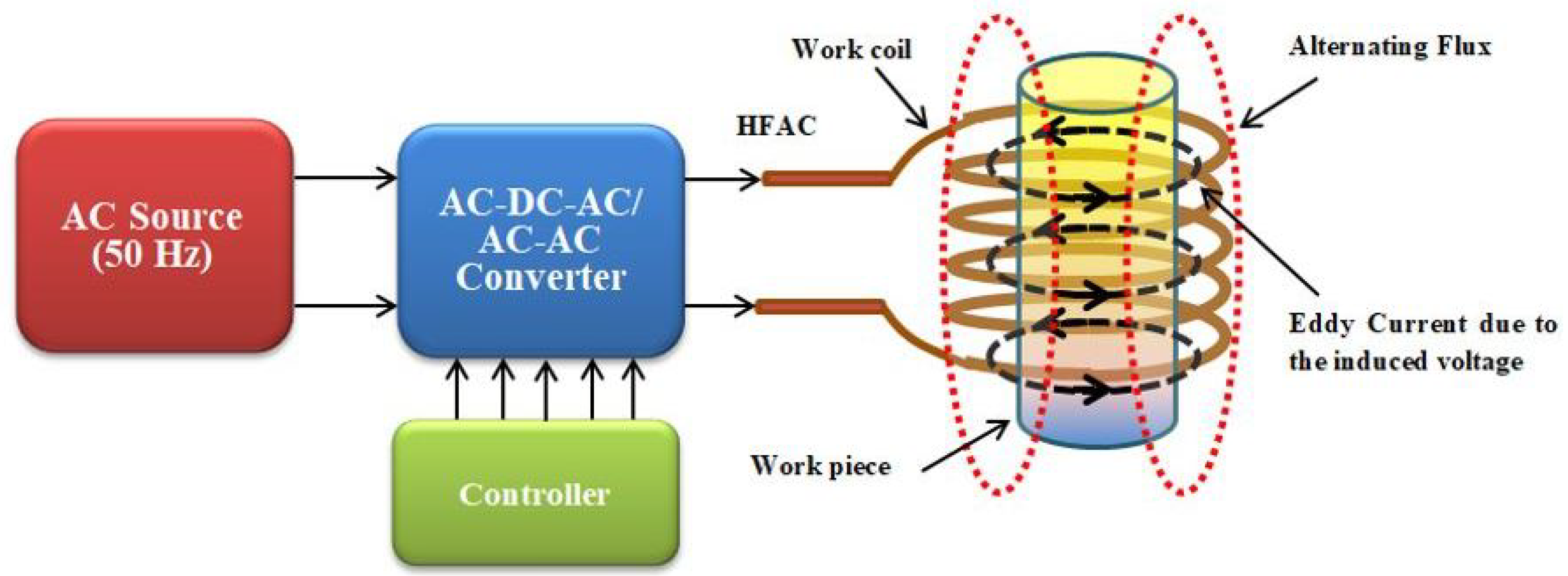
The operating principle of IH is demonstrated through a diagrammatic representation shown in Figure 1. Here, a high-frequency alternating current (HFAC) is supplied to the working coil to generate the alternative magnetic field. The material to be heated up (work piece) is submerged in it. At this juncture, it is prudent to be aware of two diversified phenomena, namely Foucault current (eddy current) and magnetic hysteresis losses [18]. The Foucault current flow is caused on the surface of the load when the work piece is short-circuited and material gets heated due to Joule’s law of heating. This methodology of IH is mostly accepted. Another method of heating related to IH can also be achieved through the hysteresis effect by using relevant ferromagnetic material. The broader view on the above methods of heat generation concludes that in both cases the losses and the magnitude of the heat depend directly on the frequency of the supply. Therefore, the selection of the range of operating frequency influences the magnitude of the resultant heat and in turn, the appropriate application; say, a few kHz for domestic and industrial applications and a few MHz for medical applications.
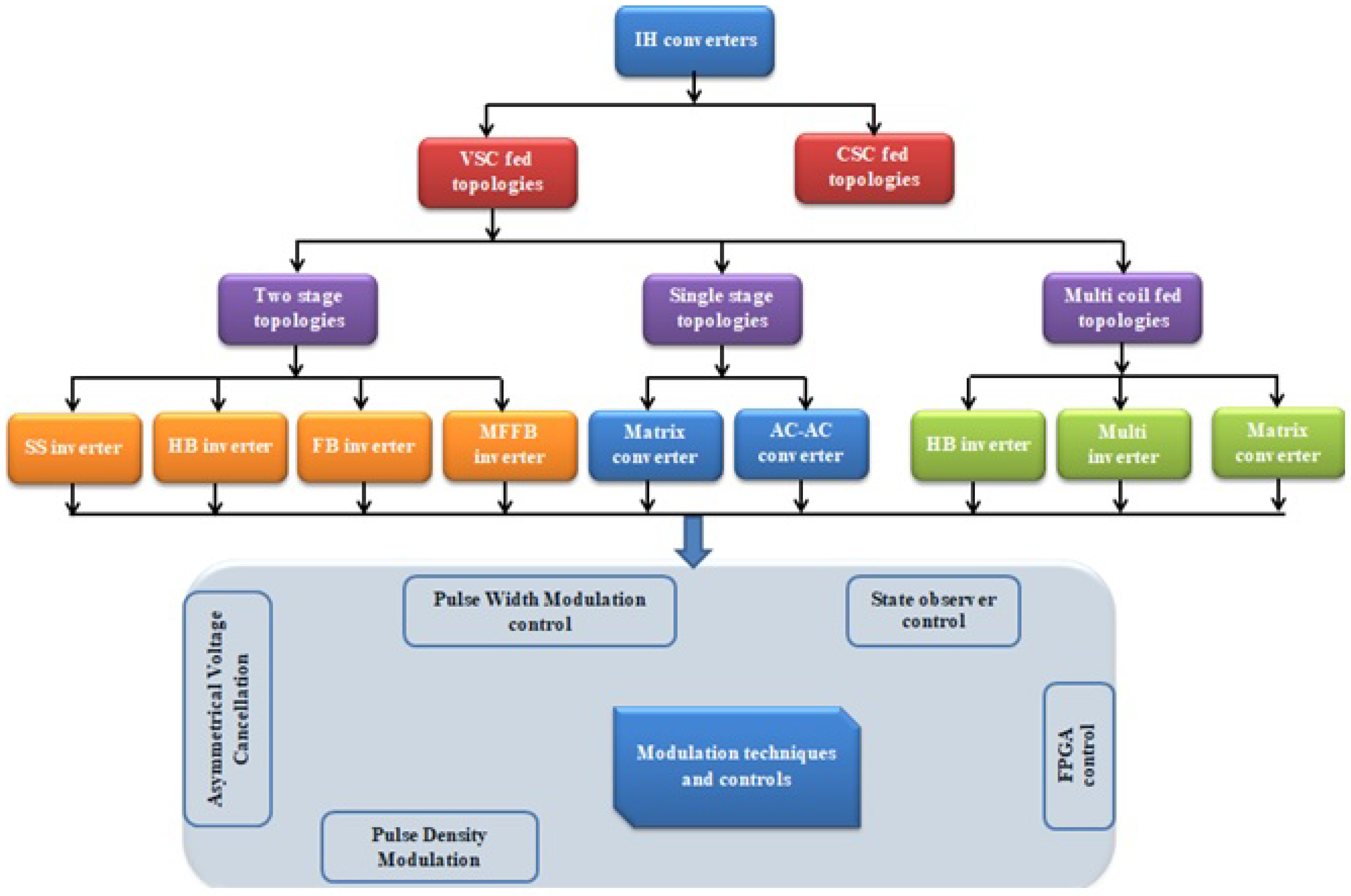
The selection of topologies of the power converter, switching frequency, and their performance characteristics decide their compliance towards the particular application. Hence, a detailed study was needed in order to analyse the compatibility of the application with converters and its switching. General structure of power converter topologies and modulations applied to the IH system is shown in Figure 2.
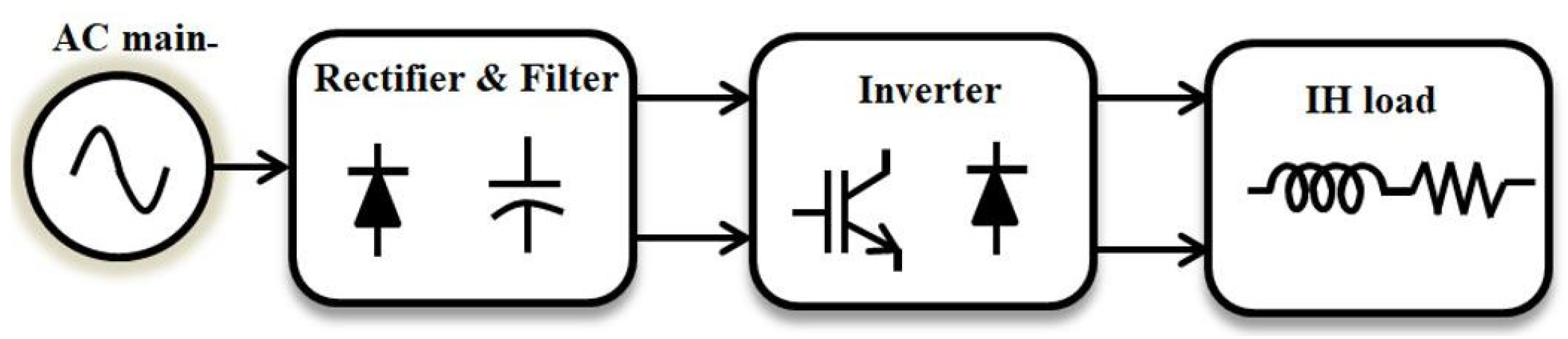
Conventional AC mainly produces 50 Hz of alternating current which requires conversion into a high-frequency current to generate a higher Foucault current. Thus, various power conversion methods have been used. Two-stage power conversion schemes are said to have advantages such as high voltage regulation and good stability, which is claimed by many researchers [19,20,21]. The first stage of conversion (which contains two stages) is generally realised through a full-bridge circuitry, where the AC supply of 50 Hz is rectified with the uncontrolled diode bridge rectifier. In the second stage, a high-frequency inverter facilitates DC to HFAC. In both stages, the filter designs are vital to improving the overall efficiency and meeting the power quality compliances. Many research papers address the voltage spike mitigation issues and other power quality issues to comply with electromagnetic compatibility [22,23]. To increase the system efficiency and to reduce the number of semiconductor switches, single-stage IH topologies have been developed with and without EMC filters [24,25,26].
From the literature, it is evident that the quest of proposing a new control algorithm which is competent in alleviating the switching loss and accurate power regulation is very meaningful. This work emphasizes the development of a novel digital AVC-PDM technique to overcome the pertinent drawbacks of the conventional control schemes. The control scheme proposed here is compared with an existing modulation scheme. This review not only summarises the state of art of power converters, modulation techniques and a control algorithm used in various IH applications but also proposes the hybrid modulation technique to achieve a high level of power control with higher efficiency.
The course of this paper is organised as follows: Section 2 describes the antiquity of induction heating systems, and various converter topologies are described in Section 3. Section 4 deals with the modelling of an induction heating load. Various modulation techniques in induction heating are explained in Section 5, and various control techniques in induction heating are explained in Section 6. Contemporary research on induction heating and its applications, as well as critical remarks are summarised in Section 7. A birds-eye view in the IH arena is explained in Section 8. Finally, in Section 9, the main conclusion of this paper is presented.

2. Antiquity of Induction Heating Systems

The evolution of IH occurred in the early 18th century [27]. The observations of Francois Arago on eddy currents helped Michael Faraday to extend electromagnetic theory in 1867. Furthermore, the classical unified electromagnetic field theory proposed by James Clerk Maxwell discovered that heat is produced when a current passes through a coil. These contributions assisted in framing the fundamental principle of IH. In 1887, Sebastian Ziani de Ferranti applied for a first industrial patent on IH and melting systems after improving induction coils, and the induction furnace was first developed by F. A. Kjellin in 1891.
The advancements in IH turned a new leaf when Edwin F. Northrup constructed an induction furnace in 1916. He developed a furnace with a cylindrical crucible and a high-frequency spark-gap power supply. Major companies such as Baker and American Brass utilised this for melting platinum and non-ferrous alloys. Around the same period, high-frequency IH technology was developed with a spark-gap generator by M. G. Ribaud; later, in 1922, an IH system with high-frequency machine generators and vacuum tubes was developed by Valentin P. Vologdin.
In the 1920s, the IH applications gained even more traction, and many practical applications emerged. Furthermore, IH got a facelift when its applications were expanded to the surface hardening of steels; in 1927, Midvale Steel explored this, and the technology further improved when Ohio Crankshaft Company employed this method in the 1930s. This paved the way for many industries to employ large-scale surface heating of metals. During the Second World War, induction technology played an important role in heat treatment on weapons in order to strengthen them, and later, it was used in the automotive and aircraft industries.
Since antiquity, silicon and its counterpart have been shown to be excellent in exhibiting semiconductor properties, which in turn helped in advancement in the discipline of solid state devices. Thyristor, known for its high current capacity, was the pioneer to these devices. Later, the invention of the high-frequency semiconductor devices such as the power bipolar junction transistor (BJT) and the power metal–oxide–semiconductor field-effect transistor (MOSFET) meant IH technology continued to boom. With these highly efficient power switches with intelligent programmable modules, a high-powered converter could be developed with higher efficiency. The introduction of the insulated gate bipolar transistor (IGBT) in semiconductor technology added the additional merit of handling high voltage in IH systems in the industrial environment. Now, IH technologies are moving towards a system which has higher efficiency; reliable converters make them more versatile and mean they can spread universally. In all, domestic heating systems adopt IH technologies because of the indirect heating and non-contamination of food while heating. In the medical field, IH technologies are used for areas that require heat precision and to achieve localised heat for hyperthermia treatment.

3. Converter Topologies for Induction Heating

Innovation in power electronics has extensively contributed to the development of IH technology [28]. The heart of IH topology is the inverter. Based on the supplied input to the inverter, it has been classified as various power stage conversions. Quite often, there will be two-stage conversions, where the input AC will be converted to regulate DC in the first stage and then it will invert in the second stage. In some applications, the AC voltage is directly applied to the IH system, and this scheme is called single-stage power conversion. The eddy current generation needed for IH is extracted from an inverter, which changes the fixed frequency, fixed voltage quantity to variable voltage and variable frequency. The frequency variation has a direct impact on the eddy current magnitude [29]. As eddy current depends on the frequency, for IH, usually, the frequency is chosen as higher than 20 kHz to avoid audible noise and rises up to 1 MHz depending on the applications.
Two types of inverter, namely voltage source inverter and current source inverter, are used for IH applications to obtain high power density [30,31,32,33,
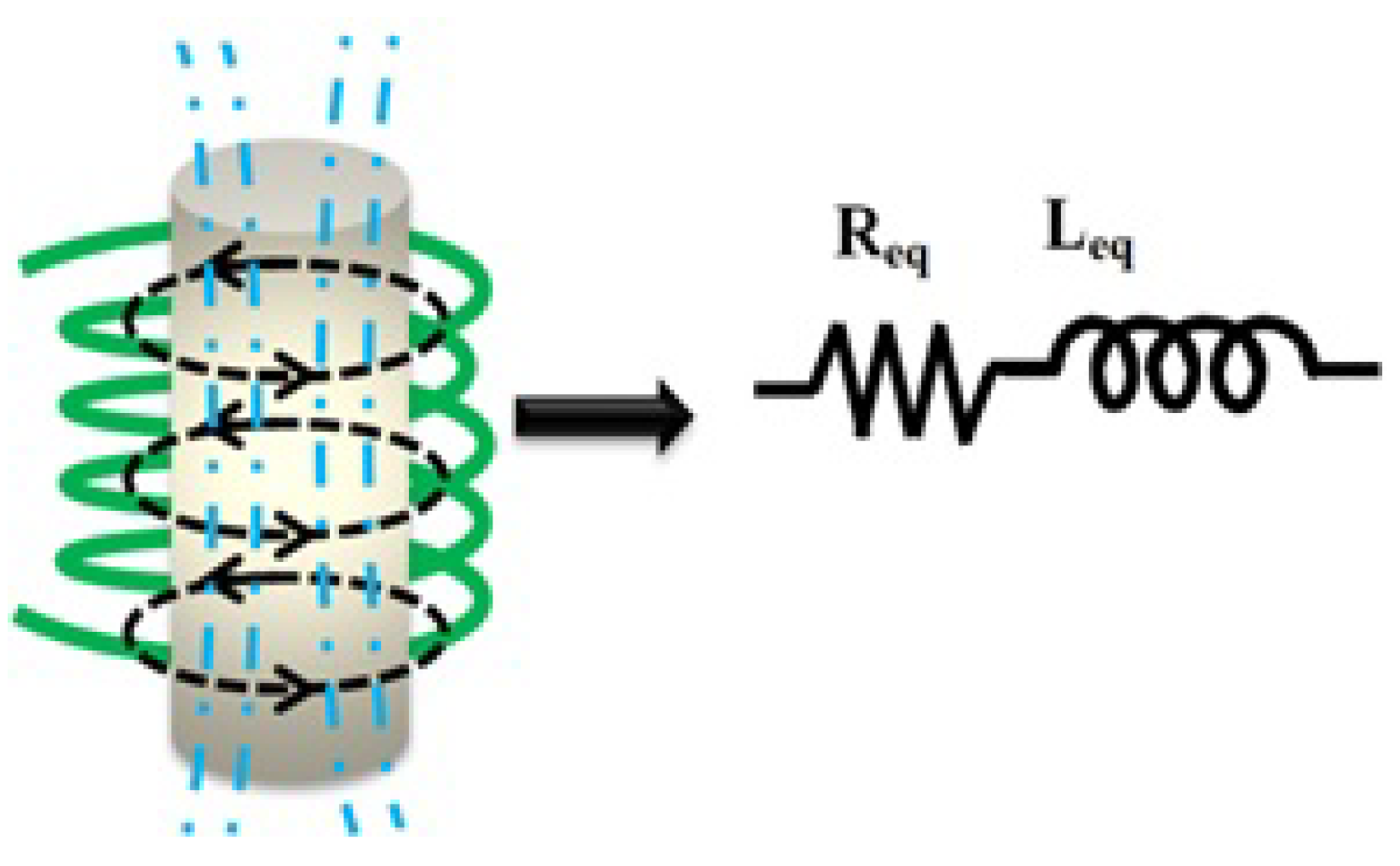
34]. IH load is modelled as equivalent resistor R e q and equivalent inductor L e q [35,36], as shown in Figure 3. The practical load representation of the IH is a series connection of both R e q and L e q . The applied power supply, geometry of the coil and the current flowing through the coil defines the heating of the coil. In addition, the distance between the placement of the work coil and the work piece and applied frequency influence the performance of IH. The effect of these load parameters in IH is listed in Table 1.
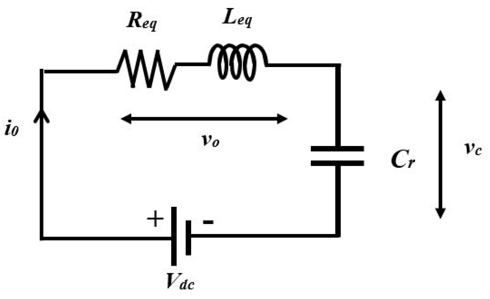
The frequency control of IH is made more competent when resonant converters are employed. An RLC resonant tank is constituted by adding the additional resonant capacitor, C r , in the circuit. The main purpose of this capacitor is to generate the HFAC sinusoidal current to heat the load. Based on the arrangement of the C r either in series or parallel with respect to the load, the circuit is termed as a series resonant inverter (SRI) [5,15,22,32] or parallel resonant inverter (PRI) [30,33,34,36,37,38]. Generally, the RLC series resonant circuit is most predominately used for a voltage source inverter (VSI)-fed IH system, which ensures the average current flowing through the inductor is zero because of the series capacitor. Zero voltage switching (ZVS) is realised in the inverter switches when it is operated above the resonant frequency [5]. An RLC parallel resonant circuit is used for CSI-fed IH topologies, which reduces the current flowing through the switches. Zero current switching (ZCS) is realised here in this inverter. PRI is chosen for the applications that require a high current. Thus, soft switching, i.e., ZVS or ZCS, results in lesser switching losses, which enhances the overall system efficiency [43].

3.1. Small Signal Modelling of Converter

The small-signal model of the half-bridge series resonant inverter is developed in this section. The equivalent circuit of SRI-fed IH load shown in Figure 4 could be modelled using the following state equations [44]:
By applying KVL to the circuit shown in Figure 4, the following expressions were obtained:
L e q d i 0 d t + v c + i 0 R e q = V d c
C r d v c d t = i 0
The active power is expressed as
P 0 = R e q i 0 2 2
The harmonic approximation of capacitor voltage and inductor current is
i 0 ( t ) i v ( t ) cos ( ω s t ) + i h ( t ) sin ( ω s t )
v c ( t ) v v ( t ) cos ( ω s t ) + v h ( t ) sin ( ω s t )
The describing function of input, voltage is given by
v 0 = 4 π V d c sin ( 2 π D ) sin ( ω t ) = v e sin ( ω t )
where
v e = 4 π V d c sin ( 2 π D )
Equations (4)–(6) are substituted into Equations (1) and (2). The resulting equations are decomposed separately as sine and cosine terms using the harmonic balance procedure as shown below.
Sine terms:
d v h d t = i h C r + ω s v v
d i h d t = v h i h R e q + v v L e q + ω s i v
Cosine terms:
d v v d t = i v C r + ω s v h
d i v d t = v v i v R e q L e q + ω s i h
Solving Equations (8)–(11), the operating point is obtained by setting all derivatives as zero. The harmonic components are given by
I h = V e ω s 2 C r 2 R e q Ψ
I v = V e ω s C r ( 1 ω s 2 L e q C r ) Ψ
V h = V e ( 1 ω s 2 L e q C r ) Ψ
V h = V e ω s R e q C r Ψ
where
Ψ = ω s 4 C r 2 L e q 2 2 ω s 2 C r L e q + ω s 2 C r 2 R e q + 1
The inputs, the state variables and the output are the perturbed variables and is of the form
h ( t ) = H + h ^ ( t )
where H is at the operating point, and h ^ is a small amplitude perturbation. The linearised model can be obtained by applying Taylor series expansion and considering the first-order partial derivatives, the perturbed variables could be replaced in Equations (8)–(11). Equation (9) could be written as
d i h d t = f ( v h , v v , i h , i v , D , v e , ω s )
hence, its linearised equation is
d v ^ h d t f v h v ^ h + f v v i ^ h + f i h i ^ v + f ω s ω ^ s + f v e v ^ e + f D d ^
where each f v h is estimated at the operating points. The complete linearised model is given as
d v ^ h d t = i ^ h C r + ω s v ^ v + V v ω ^ s
d i ^ h d t = v ^ h L e q R e q L e q i ^ h + ω s i ^ v + I v ω ^ s + 2 V e L e q cos ( 2 π D ) v ^ e + 2 V e L e q sin ( 2 π D ) v ^ e
d v ^ v d t = i ^ v C r ω s v ^ h V e ω ^ s
d v ^ v d t = v ^ v C r R e q L e q i ^ v ω s i ^ h I h ω ^ s
The state space model representation of the model is given as
X ˙ = A x + B d u 1 + B ω u 2
y = C x
where x and y are the input and output state variable vectors, respectively.
X ˙ = i ^ s i ^ c v ^ s v ^ c T
y = p ^ 0
Thus,
X ˙ = R e q L e q ω s 1 L e q 0 ω s R e q L e q 0 1 L e q 1 C r 0 0 ω s 0 1 C r ω s 0 x + 2 L e q cos ( 2 π D ) 2 L e q sin ( 2 π D ) 0 0 v ^ d c + I v I h V v V h ω ^ s
y = R I h R I v 0 0 x
The perturbed output power is given as
p ^ 0 = R I h i ^ h + R I v i ^ v
Thus, the small change in output power with respect to system dynamics of the SRI can be obtained by Equation (30).

3.2. AC-DC-AC Converter Topologies

The general block diagram of a two-stage power conversion scheme is shown in Figure 5. The various inverter topologies used for IH applications are a single-switch (SS) resonant inverter [40,45,46,47], a half-bridge (HB) inverter [5,20,43,48,49,50,51,52] and a full-bridge (FB) resonant inverter [44,53,54,55,56].
SS resonant inverters are used in the medical field where the power requirement is less than 2 kW. Since only one single switch exists, the conduction losses and switching losses are much lower. The simple control mechanism is enough to control it. However, the major drawback of this topology is the high switching stress, as the sole switch has to sustain the total power capacity of the circuit during switching. So, this topology is hardly used for high-power industrial applications [45]. For the load power requirement between 2 kW to 5 kW, HF inverters are used. The HF inverter finds its applications in domestic heating. As it has two semiconductor switches, the stress across the switches is divided equally [48]. The enhancement in the HF inverter was developed in [49] with a switched auxiliary capacitor. This increases the power density of the inverter more than the FB SRI. For high-power IH applications, FB resonant inverters are preferred to share the switching stresses and to have uniform power control. This topology is generally used for the industrial applications whose power ratings are greater than 5 kW. The FB multiple-frequency SRI has a centre-tapped transformer. This arrangement makes the load frequency twice as high as the switching frequency [39]. The comparison of various VSI-fed IH topologies is shown in Table 2.
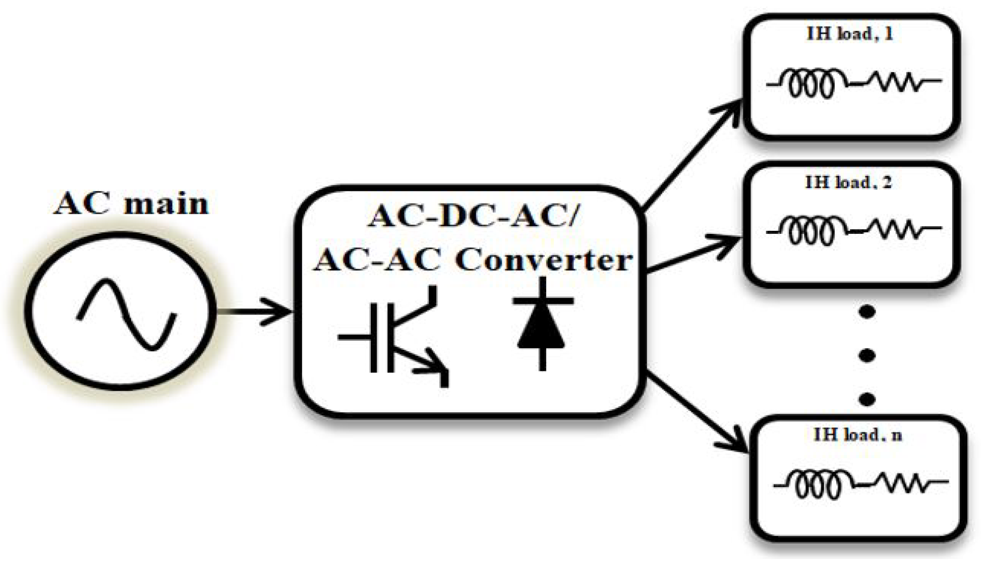
In order to improve the heat distribution and to feed power to multiple loads, the multi-coil-based IH system was developed [39,40,41,42,57,58,59,60,61,62,63,64,65,66]. These topologies are used in both domestic and industrial applications. This topology uses the normal HF and FB resonant inverter topologies with supplementary modifications. The general block diagram of multi-coil-fed IH topology is shown in Figure 6. In [60], the IH system with HB inverter and FB inverter are combined to perform the operation of two FB inverters. This topology facilitates a single input and multiple outputs since one particular leg of the inverter is shared by both inverters. If one or more loads are connected at the output, the loads can be controlled simultaneously and independently. An HB SRI with multiple loads is presented in [59]. Multiple loads connected at the output are controlled by the inverters’ switches, and switching takes place in accordance with the power management algorithm so that simultaneous control is possible. The uniform power distribution among the loads is carried out when they are connected in parallel. Since all the erected loads require the same power, this topology is beneficial for low-power applications. For high-power applications and to control the power independently, the series resonant multi inverter was developed in [64]. This topology contains a common inverter block and a resonant load block. An inverter block interacts with the source DC supply and converts it to AC, whereas the switch connected in series with the load ensures the connection of load with an inverter. Thus, by connecting more switches, loads can extend further. This topology is generally preferred for domestic applications because of the lower cost, size and extensive use of inductors. Later, a double half-bridge resonant inverter supplying inductive loads with a common resonant capacitor was proposed in [65]. In this topology, a common resonant capacitor was used for two different loads to control the output power. It reduces the number of components in the circuit. Furthermore, it forms a cost-effective solution for domestic induction heating appliances, with two burners heating up the two pots simultaneously. A comparative analysis of load handling capacity and output power expression is shown in Table 3.
Table 2. Summary of various parameters in AC–DC–AC VSI-fed IH topologies.
Converter TopologyNumber of Semiconductor SwitchesOutput Power ExpressionPower RatingModulation TechniqueEfficiency at Rated PowerOperating FrequencyChoice of Application Parameter (s)
SS inverter [40]5 P 0 = V i n 2 cos 2 ϕ π 2 R e q 700 WPWM90%1 MHzIH system-approximate load analysis
HB inverter [48]6 P 0 = 2 V i n 2 cos 2 ϕ π 2 R e q 2.25 kWPWM90%20 kHz–100 kHzIH system close to unity power factor and high efficiency
HB inverter with auxiliary switched capacitor [49]7 P 0 = 2.2 V i n 2 cos 2 ϕ π 2 R e q 543 WAsymmetrical PWM94.6%25 kHzIH system for high output power density
FB inverter [56]8 P 0 = 8 V i n 2 cos 2 ϕ π 2 R e q 500 WPLL based PWM94.5%22 kHzIH system for wide range of output power and high efficiency
Multiple frequency resonant inverter [39]8 P 0 = V i n 2 cos 2 ϕ 5 R e q 1 kWPWM98.86%50 kHzIH system with high frequency and efficiency
Table 3. Summary of various parameters in multi-coil IH topologies.
Converter TopologyNumber of Semiconductor SwitchesOutput Power ExpressionPower RatingModulation TechniqueEfficiency at Rated PowerSwitching FrequencyChoice of Application Parameter (s)
Two output series resonant inverter [60]6 P 0 = 8 V i n 2 cos 2 ϕ π 2 R e q 3.2 kWAVC-10 kHz–200 kHzIH system to control the load independently with less acoustic noise
Multi-load half-bridge inverter [59]2 P 0 = 2 V i n 2 cos 2 ϕ π 2 R e q 1.1 kWPWM-20 kHz–150 kHzIH system with multiple load and single frequency system
Series resonant multi-inverter [64]N + 2 P 0 = V i n 2 cos 2 ϕ π 2 R e q 600 WPWM98.2%75 kHz–100 kHzIH system with low cost and high power density
Double half-bridge inverter [65]4 P 0 = 2 V i n 2 cos 2 ϕ π 2 R e q 2.5 kWPhase shift PWM95%20 kHz–100 kHzIH system with simultaneous heating of two burners with lower cost

3.3. Direct AC–AC Converter Topologies

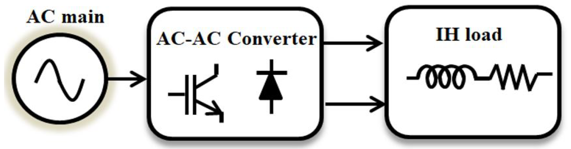
To increase the efficiency of the system topology and to reduce the number of components, single-stage AC–AC resonant converters have been proposed [24,26,67,68,69,70,71,72,73,74,75,76]. Figure 7 shows the general block diagram of the single-stage power conversion topology. In these topologies, 50 Hz AC is directly converted into a high-frequency AC current which ignores the rectifier unit. A typical dual-stage conversion injects more harmonics to the supply, which reduces the input power factor. To overcome this problem, a single-phase matrix converter is proposed for IH applications [74]. This topology maintains the sinusoidal current at the input side and the inverter switches are operated with soft switching conditions.
In [73], an antiparallel bidirectional IGBT switch-based cyclo-converter is used for IH applications. In this topology, the asymmetrical duty cycle PWM control method is proposed for converting 50 Hz AC to a high-frequency AC current. The resonant capacitor assists soft switching in the inverter. Although there are many advantages in the matrix and cyclo converters, the switching algorithm design remains an uphill task. HB topology featuring fast diode rectifier is proposed in [26]. This topology only uses two diodes to rectify the AC main, which reduces the conduction losses. Furthermore, both the switches are operated with ZVS during the turn on and turn off period. The meritorious advantage of this scheme is that it has a boost inductor, which boosts the output voltage to two times greater than the input voltage for the constant output power. This reduces the current flowing through the switches. To control the output power with a reduced number of switches, a modified HB SRI was proposed in [68]. A new topology that assists in providing more output power is framed with a single-stage FB AC–AC converter [24]. Direct AC–AC converter topologies are proposed for multi-output power. A multiple-output resonant matrix converter with a single-output DC link inverter was proposed in [70]. This converter is used for multiple inductive cooking applications where smooth power control is required. Furthermore, this scheme reduces the overall system cost and increases the power density and efficiency of the system. Table 4 shows the details of various output parameters with respect to different topologies. The researchers can easily relate the choice of topology with respect to the parameters with which they are concerned in their research.
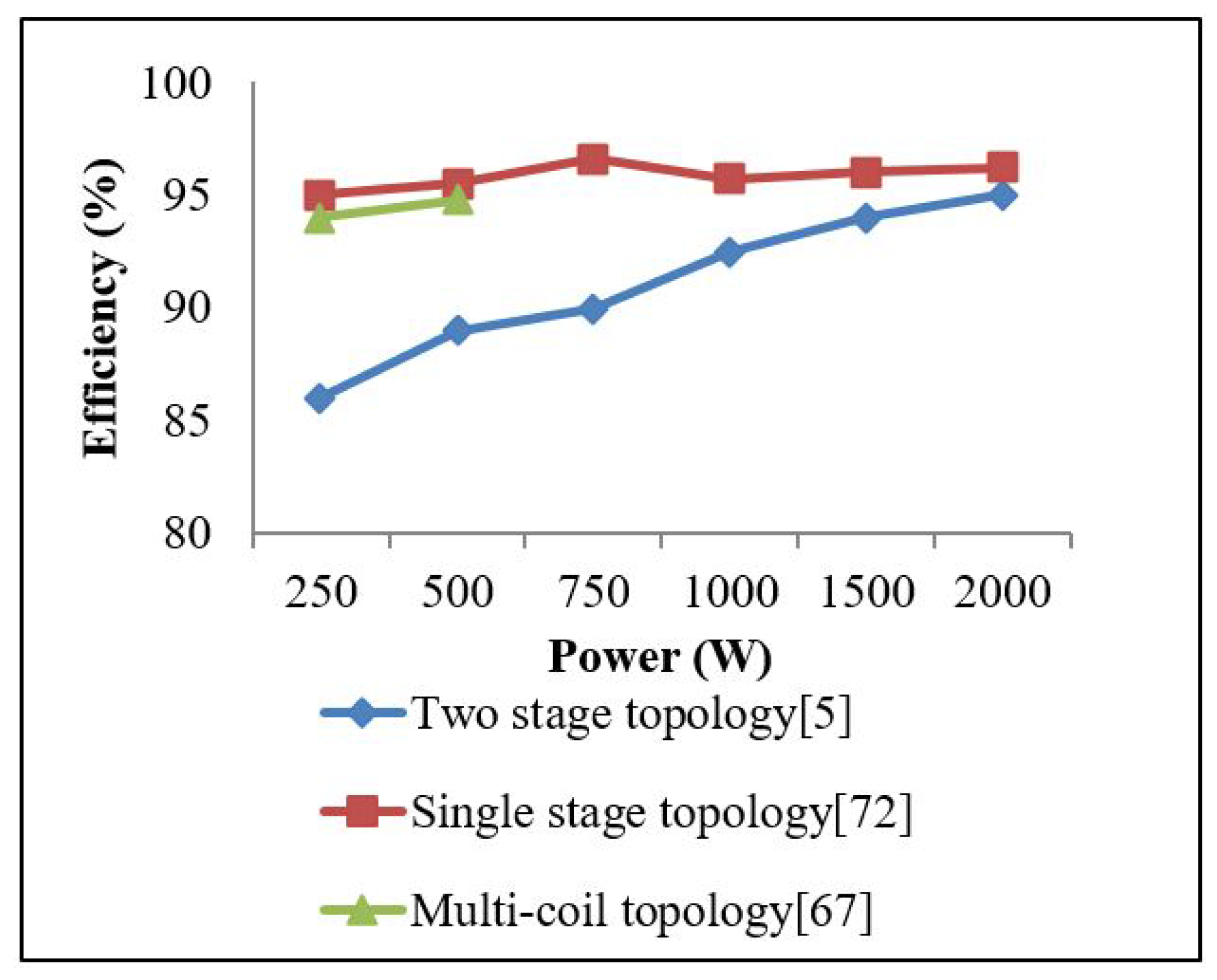
The comparison of the efficiency of various IH topologies is shown in Figure 8. It is observed that the efficiency of single-stage topology is higher when compared to the other two topologies. This is because of the lower number of semiconductor switches and the absence of power stage conversion.

4. Modelling of an Induction Heating Load

This section deals with the electrical and thermal modelling of the IH load.

4.1. Electrical Modelling of an Induction Heating Load

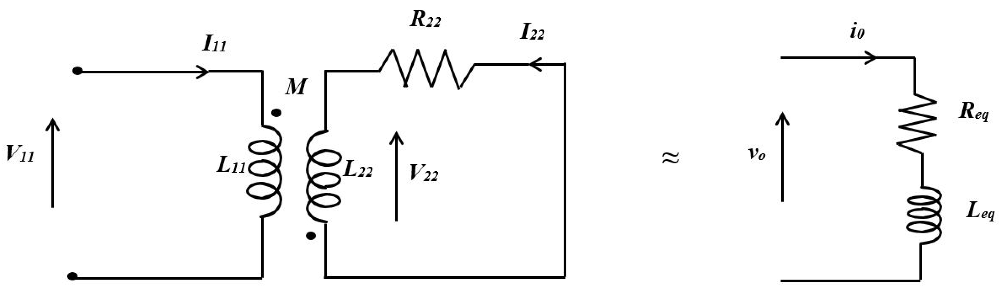
In an IH system, due to the presence of electrical isolation between the work coil and work piece, the transfer of energy takes place via magnetic coupling. As it resembles transformer action with secondary circuits, the electrical equivalent of the IH load can be modelled as a transformer with a short-circuited secondary. The electrical equivalent model of the IH load is shown in Figure 9.
The application of KVL to the equivalent circuit is shown as:
V 11 = j ω s L 11 I 11 j M ω s I 22
0 = j ω s I 11 M + ( R 22 + j ω s L 22 ) I 22
where
ω s = 2 π f s
Current I 22 is given as
I 22 = j ω s M I 11 R 22 + j ω s L 22
The substitution of Equation (34) in Equation (31) is given as:
V 11 = ( ω s 2 M 2 R 22 R 22 2 + ω s 2 L 22 2 + j ω s [ L 11 R 22 2 + ω s 2 M 2 L 22 ( L 11 L 22 + M 2 ) R 22 2 + ω s 2 L 22 2 ] ) I 11
Simplifying the above equation in real and imaginary parts and equating the real part as R e q and the imaginary part as L e q :
R e q = ω s 2 M 2 R 22 R 22 2 + ω s 2 L 22 2
L e q = L 11 + ω s 2 M 2 L 22 R 22 2 + ω s 2 L 22 2
The mutual inductance is
M 2 = R e q ( R 22 2 + ω s 2 L 22 2 ) ω s 2 R 22
The expressions in Equations (36) and (37) are used for the calculation of equivalent resistance and inductance of the IH load [77].

4.2. Thermal Modelling of an Induction Heating Load

The typical equivalent model of an IH system is shown in Figure 3. The energy equation for a lumped mass is given by
C p d θ d τ = 1 σ ( σ ω s 1 2 ) 2 ε r ( 1 + R l ) ( θ 4 1 )
where
C p = ρ c ( ρ c )
The Nagaoka coefficient is given by
K n = k n ^ ( 1 R 2 b 2 ) + R 2 b 2
where
k n ^ = 1 + 1.5356 β 2 + 0.2737 β 4 1 + 1.035 β 8 β 3 π
Equation (41) is only valid when the length of the coil is greater than the diameter or 2 β 1 . The skin depth is given by δ = ( 2 ω s μ σ ) along with the dimensional less variables β = b l and ε = δ R
The R e q and L e q are given by
R e q = 2 π σ ( σ ω s 1 2 )
L e q = 2 π σ ω s
The dimensions of the work coil and the work piece are calculated based on the functions dealt with in this Section [78].

5. Various Modulation Techniques in Induction Heating

The modulation techniques play a vital role in controlling the temperature with respect to the source and load dynamics. Diverse modulation techniques were proposed for the above-discussed converter topologies.

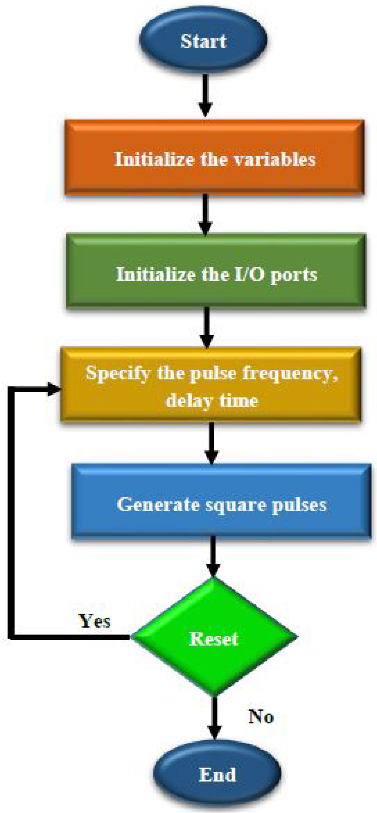
5.1. Square Pulse Control

Square pulse control is the most commonly used modulation technique applied to IH systems to control the output power [5]. The output power is controlled by either varying the duty cycle or the switching frequency. For varying loads, the power semiconductor switches enter into the hard switching mode, which increases the switching stresses. Furthermore, power can be controlled from 40 to 60% of the rated power. A flow chart of square pulse generation is shown in Figure 10.

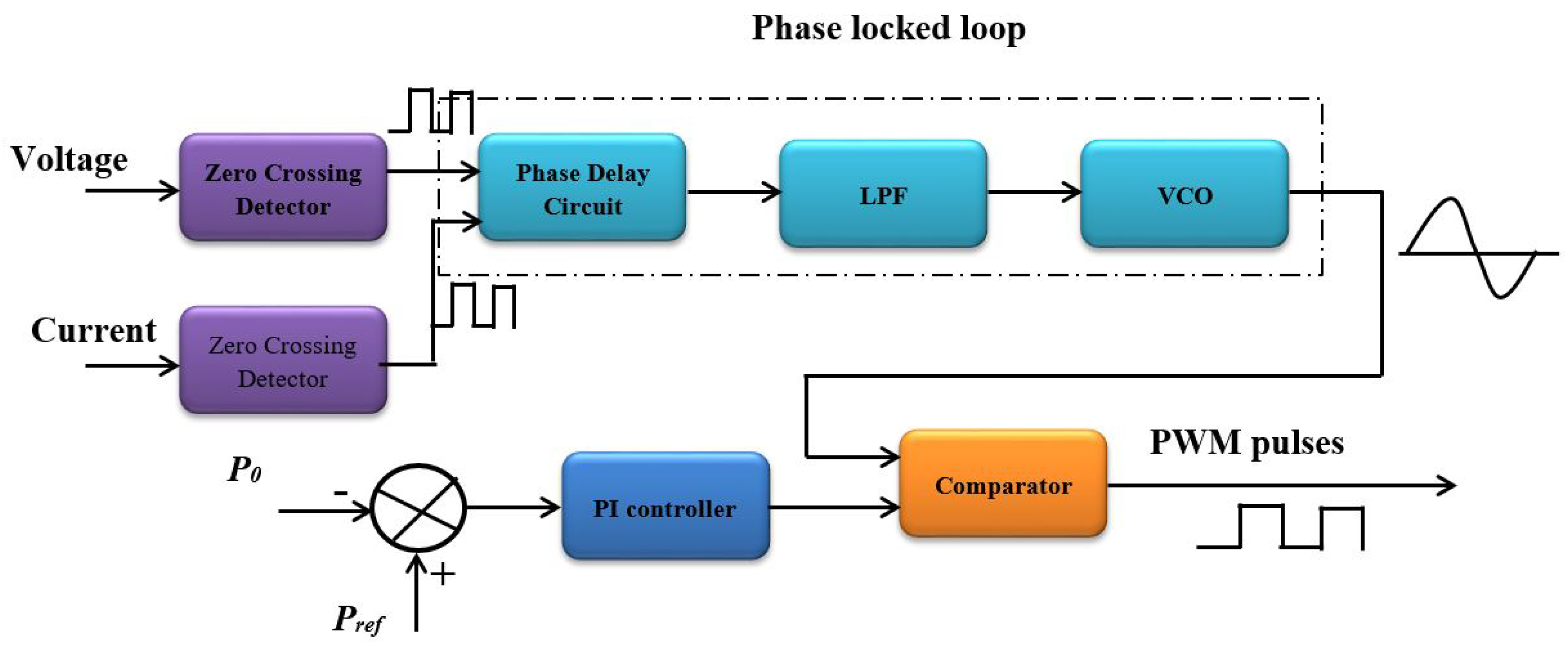
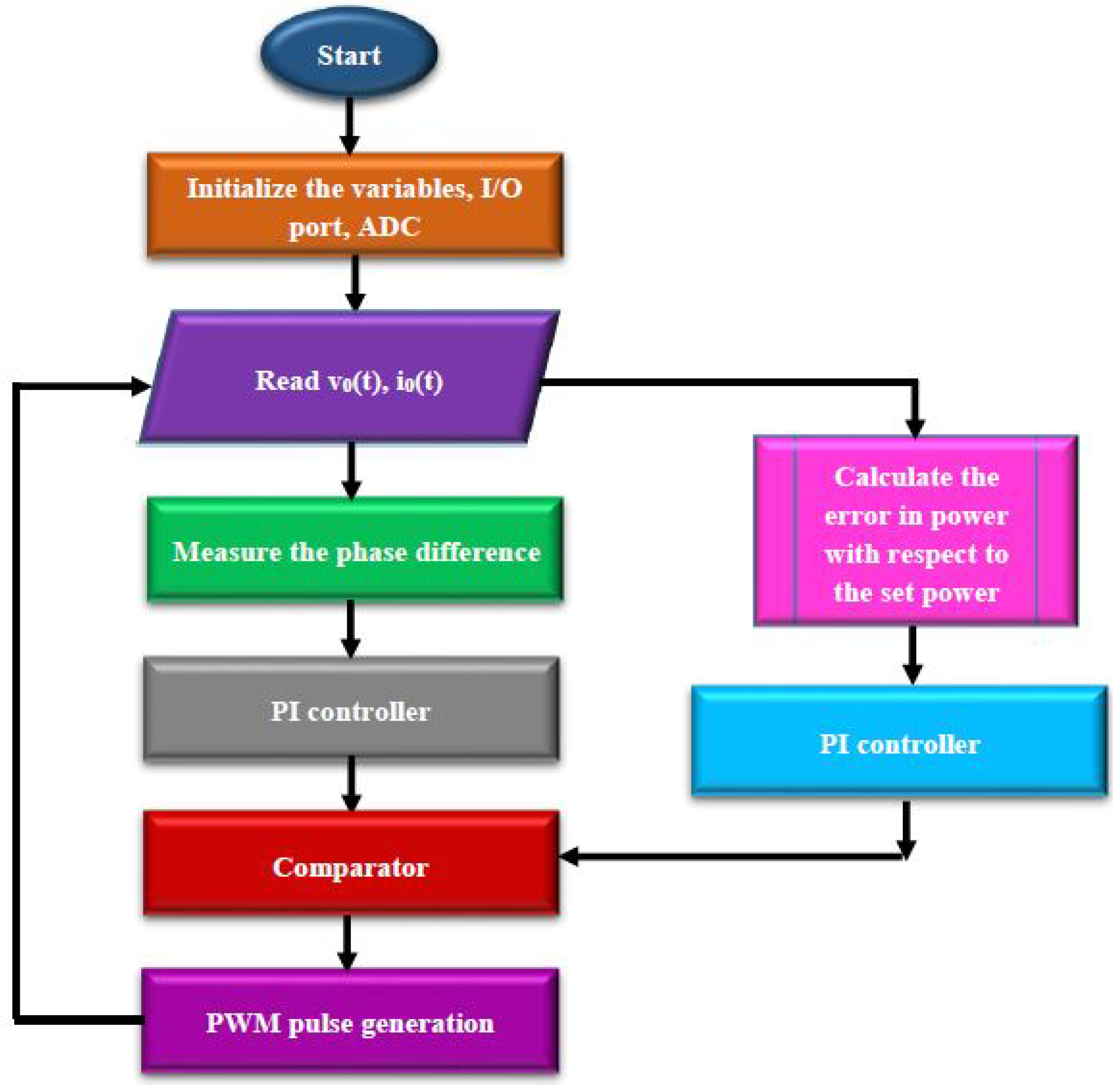
5.2. PLL-Aided PWM Control Technique

The most commonly used pulse with modulation [79] is applied to the IH system to control the output power. For varying loads, the power semiconductor switches enter into the hard switching mode, which increases the switching stresses. To overcome this problem, two loop controls were developed with a phase-locked loop (PLL) and PI controller [41,44,79,80]. A PLL, first loop control, is used to track the resonant frequency to maintain soft switching in the inverter, and the outer loop controls the output power. The two loop controls make the system more complex and they slow down the dynamic response. This problem demanded a solution to develop a suitable modulation technique which will hold good for both soft switching and power control action. The general block diagram of PLL-aided PI control is shown in Figure 11. A flow chart of the PLL-aided PWM control technique is shown in Figure 12.

5.3. Pulse Density Modulation

Pulse density modulation is one of the most commonly used techniques for controlling the output power without changing the switching frequency [19,24,81,82,83]. PDM pulse generation is shown in Figure 13. In this control technique, the density of the switching pulses is varied according to the load requirement. The main drawback of this scheme is electromagnetic interference, as two different pulses are involved in this operation. A flow chart for the PDM control technique is shown in Figure 14.

5.4. Asymmetrical Voltage Cancellation

For soft switching and power control action, asymmetrical control was proposed in [84,85,86,87]. In this control scheme, the output voltage waveform is made asymmetric and results in a large dead band for zero crossing of the current. Furthermore, the output power is controlled by varying the RMS value of the output voltage. The AVC pulse generation is shown in Figure 15. Because of the asymmetrical voltage waveform, even harmonics will be produced. A flow chart of the AVC control technique is shown in Figure 16.

5.5. Phase Shift Control

The pulse generation phase shift (PS) control method is shown in Figure 17. This method is preferred for a wide range of power regulation schemes [88]. In this control scheme, as the switching frequency is maintained constant, two loop controls are also not required. However, for varying loads, more switching losses occur because of the hard switching. Thus, to reduce the switching losses and improve the control regulation range, PDM-based PS control is proposed. This results in a better power regulation range, but the input power is not efficiently used. A flow chart of the PS control technique is shown in Figure 18.

5.6. Proposed Control Technique

Various studies on modulation schemes have helped in assessing the problems associated with it. By having smooth power control, with fewer switching losses, cost-effective control and high efficiency as a task, a novel control scheme is developed. This control scheme uses hybrid combinations of the existing modulation techniques. The AVC control technique is generally preferred for soft switching and PDM is used to control the wide range of output power by varying the density of the pulses. This combination of modulation results in better efficiency, lower input power usage and high efficiency compared to other techniques. To validate it, the most commonly used FB inverter [44] topology-fed IH system is developed. Switching pulses, output voltage, and current is recorded using the RIGOL oscilloscope. A flow chart of the AVC-PDM control technique is shown in Figure 19.
The experimental prototype is developed to supply the induction heating load of 100 W. Commercially available 50 Hz AC is rectified using four 1N4007 diodes and four IRF840 MOSFETs are used to convert DC to HFAC. The test setup is shown in Figure 20. A PIC16F877A microcontroller is used to validate various modulation techniques.
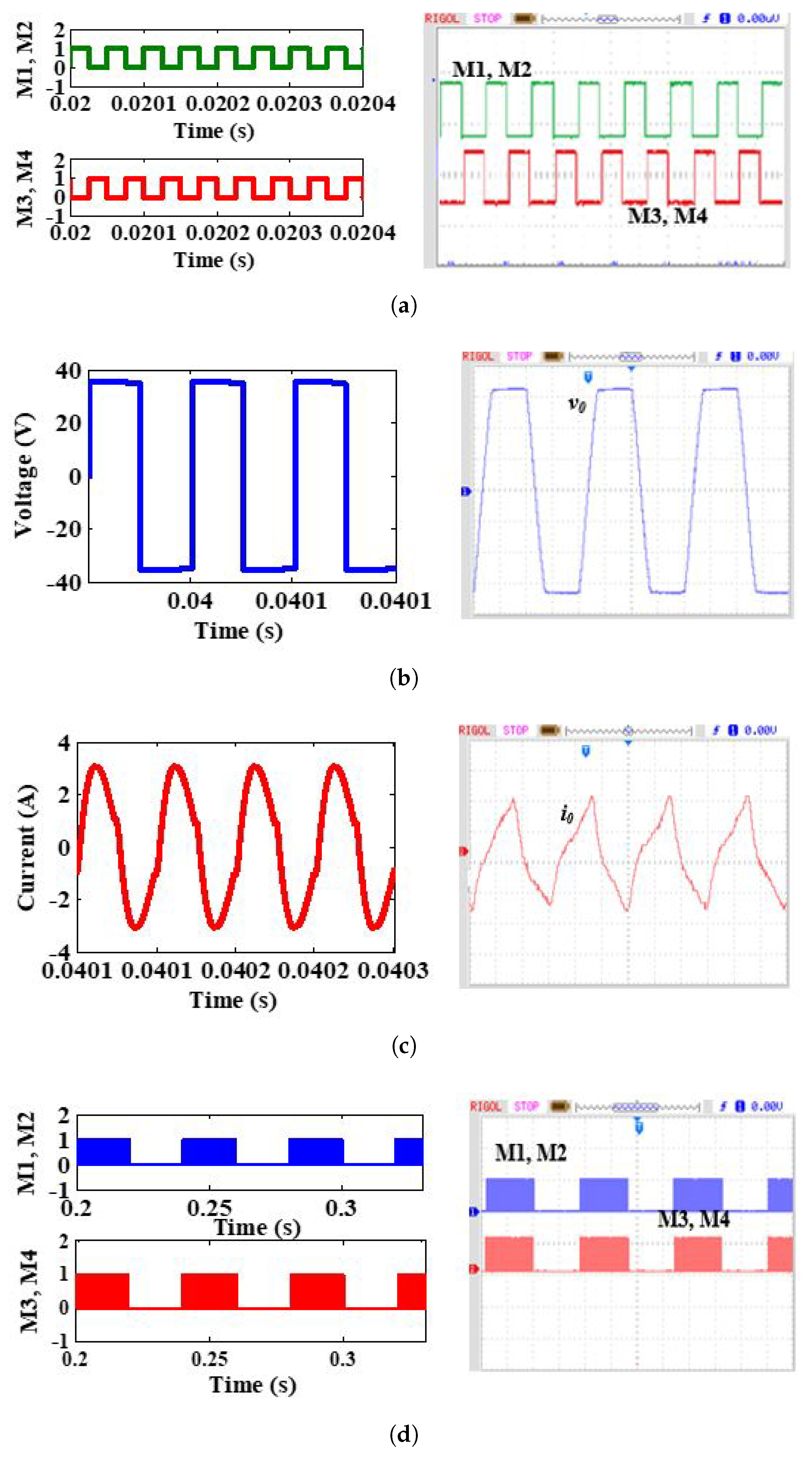
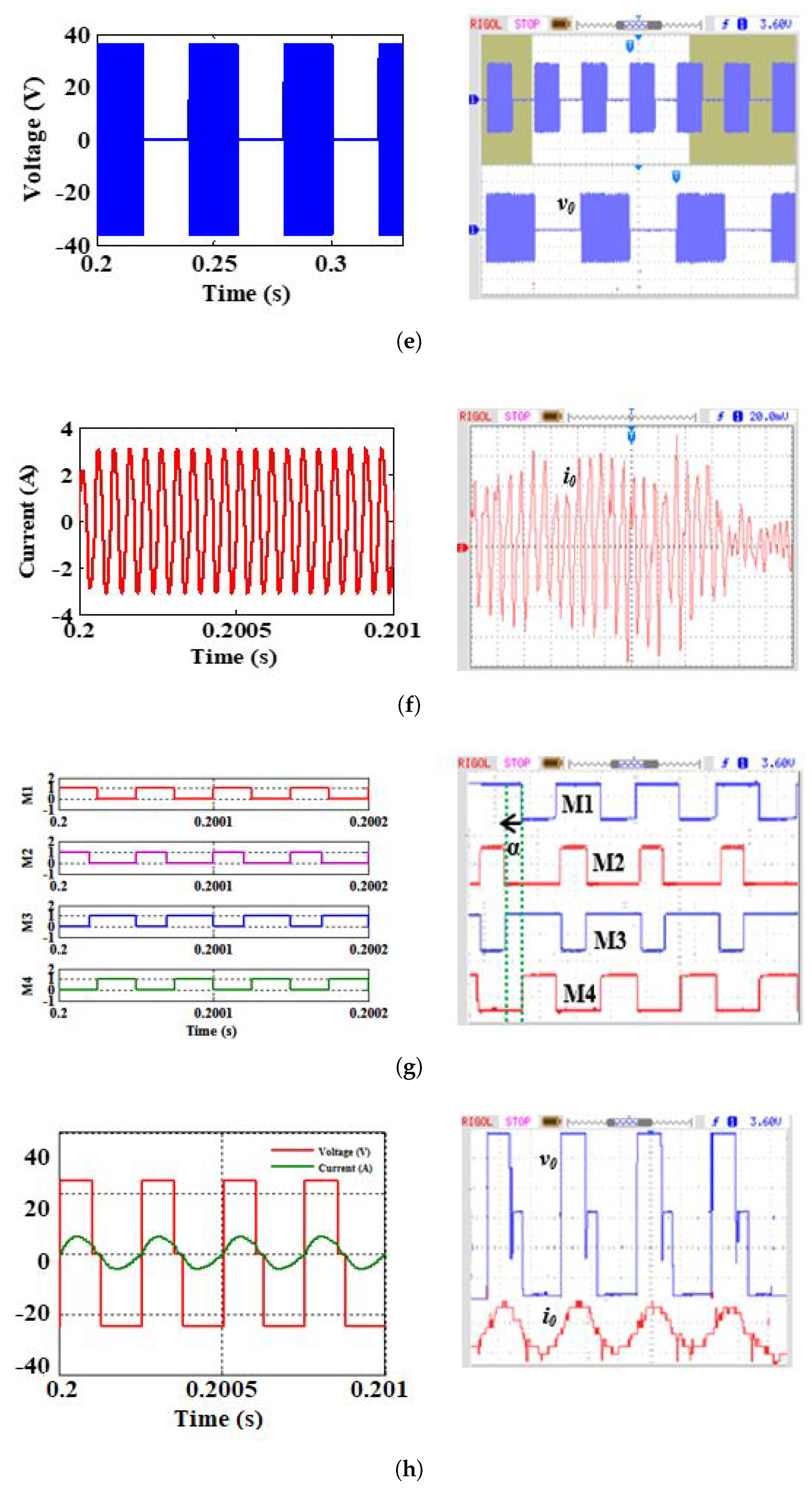
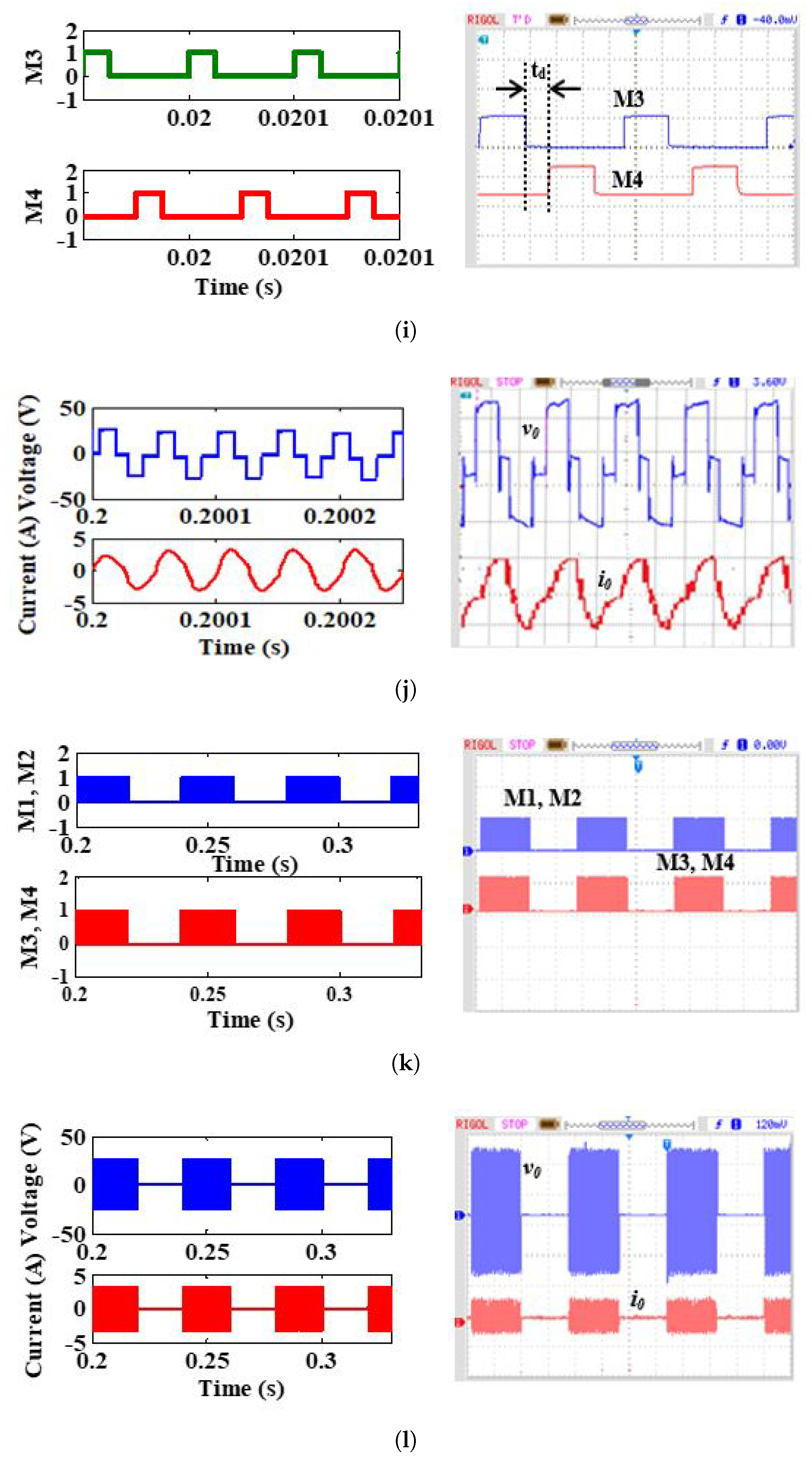
Various modulated oscillogram waveforms are shown in Figure 21. Figure 21a–c show the switching pulses, output voltage and current waveform with square pulse control. The switching pulses, output voltage and current waveforms with PDM control are shown in Figure 21d–f. Asymmetrical switching pulses, corresponding voltage and current are shown in Figure 21g,h. Figure 21i,j shows the switching pulses, output voltage and current waveform with PS control. Finally, Figure 21k,l shows the switching pulses, output voltage and current waveform of the proposed AVC-PDM technique. The performance comparison with various modulation techniques is shown in Table 5. Since AVC-PDM technique gives better efficiency and control range, it is most preferred among modulation techniques. Similarly, IH using another combination of the modulation techniques can be developed and its performance can be estimated. Furthermore, these modulation techniques can be applied to various topologies and its performance of the IH system can be enhanced.

6. Various Control Techniques in Induction Heating

The desired performance of the IH system is achieved only through competent control algorithms. In any IH system, the output temperature has to be varied based on the load requirements and in turn, the output voltage or current should be adjusted to satisfy the load demand.
Various control methods used for IH systems are tested in a hardware platform with various constraints such as dynamic behaviour, load transients, steady state performance of the system, etc. Initially, all the control algorithms were practically implemented with analogue processors, which have a potential divider, operational amplifier etc. [89,90,91,92]. The fast and advanced processor emerged due to developments in the field of semiconductor technology. During the initial phase, microprocessors handled the computational algorithms, but there was a paradigm shift when new handy micro controllers emerged in the silicon market. Slowly, highly configured, lower power consumption field-programmable gate arrays (FPGAs) and digital signal processors were developed [93,94,95,96,97].
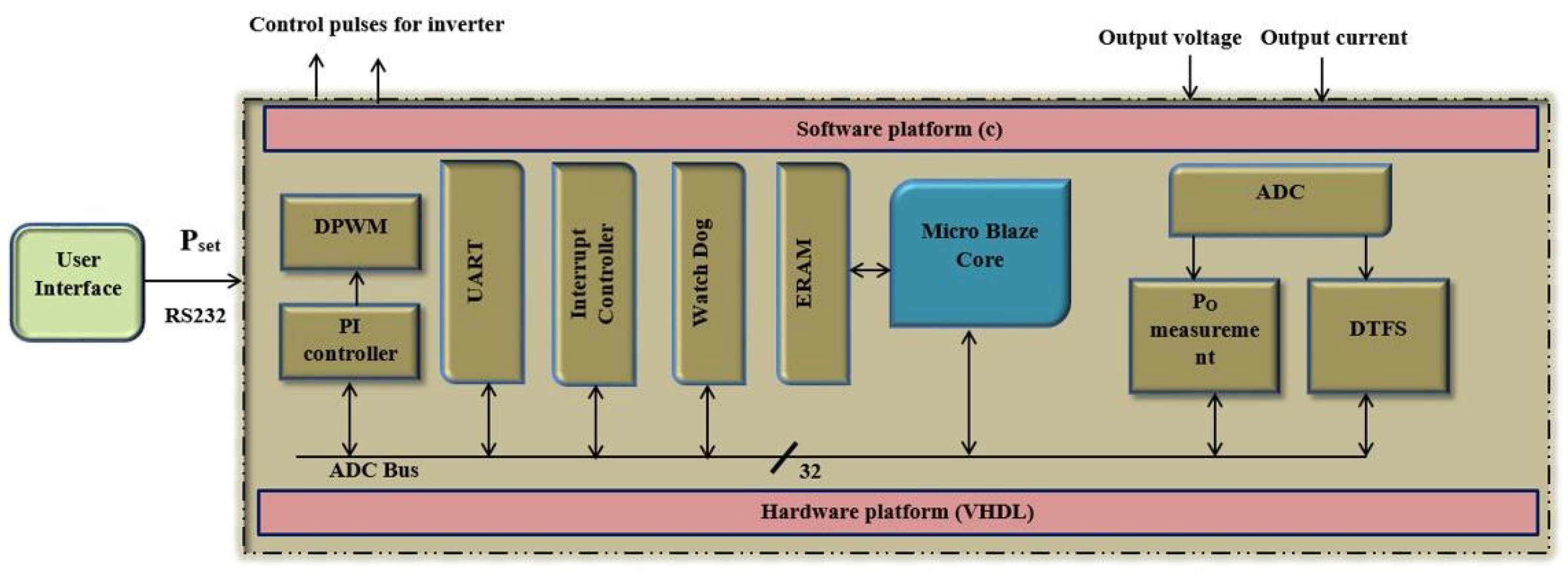
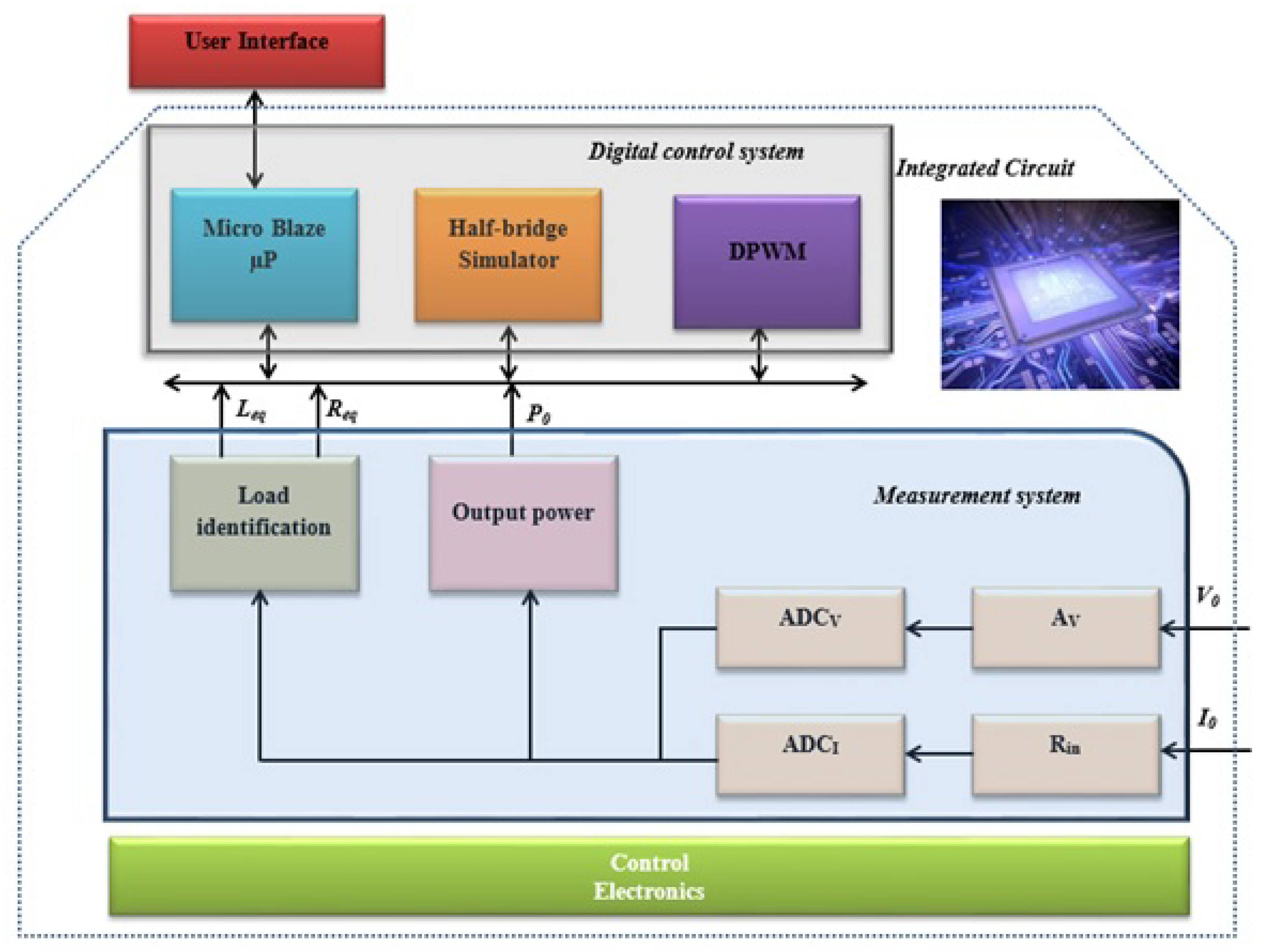
FPGA-based power control architecture for IH is shown in Figure 22. In this control scheme, online power measurement is performed by sampling the output voltage and current with 1 bit second-order sigma delta analogue to a digital converter. The bit streams of the measured data are taken into account to perform the desired task. This controller is capable of performing noise sensitivity analysis and harmonic analysis. The competency of the controllers is verified with the SRI for the frequency variation ranging between 30 kHz to 80 kHz. The control loop is properly calibrated to obtain the required output even during uncertain periods. Thus, the FPGA-based controller provides the most accurate and cost-effective solution for IH applications. Similarly, an FPGA based on line hardware loop emulator was proposed in [98]. Its architecture is shown in Figure 23. This emulator helps in obtaining the efficiency and hard switching range of the inverter. For the measured parameters, the optimised solution is obtained to control the inverter switches. The obtained solution is compared with off line simulation and hardware to find its accuracy.

7. Contemporary Research on Induction Heating and Its Applications: Critical Remarks

The applications of IH have become indispensable in domestic, industrial and medical applications. The following subsections give a detailed view on IH applications.

7.1. Industrial Melting Applications

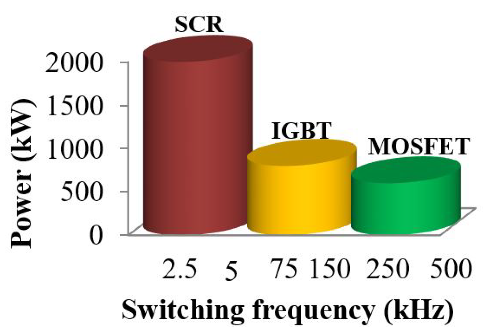
In 1900, IH was used in industries in order to melt metals. Later, it was used in aircraft and automotive industries. Now, it is used in many manufacturing companies for the pre and post heating of metals, welding, annealing, surface heating, soldering, brazing, cap sealing etc. An IH-based heating system provides a high-speed process, high precision, high efficiency and zero pollution, which are basic requirements for the automation of industrial processes. The ratings of power semiconductor switches used in industrial applications are shown in Figure 24. Based on the power rating and switching frequency, appropriate semiconductor switches can be selected. Some of the recent research connected to IH in industrial applications is shown in Table 6.
A medium-frequency coreless induction melting crucible was developed in [100] for metal melting applications. The work coil and its crucible were supplied with variable frequencies from a multi-pulse rectifier and a current-fed load-resonant cascade inverter. It was concluded that the system possesses lower source-side harmonics. A superconductor coil-based aluminium metal melting crucible was developed in [101]. An aluminium pipe of 0.77 kg was melted at 500 °C within 2 min. A superconducting magnet-based IH system was developed for melting aluminium applications [102]. The power was fed to the load with a split coil which comprised three rectangular-shaped double pancake coils on each side, and it was excited with the current of 114 A. A self-resonant coil-based IH system for metal melting application was proposed in [103]. In this, the variable frequency control was used to vary the output power and the performance comparison of solenoidal and bifilar coil was also briefed. An intelligent control method was proposed to improve the performance of power supply for tundish electromagnetic IH. The power supply consists of six power units, and each of them consists of a fore-stage three-phase rectifier and back-stage single-phase inverter. The cloud controller-based intelligent temperature control algorithm was combined with the power feed-forward algorithm to obtain accurate tracking of the output current and constant temperature control of the tundish steel in the back-stage inverter [104]. A three-phase AC–AC resonant converter for application in induction melting was developed with three coils in a coaxial arrangement [105]. A 10 kW prototype was developed and operated in ZVS mode, which resulted in minimum switching losses.

7.2. Household Applications

In household appliances, widely used IH-based systems include induction stoves, induction cookers, inductor heaters, etc. As there is no need for a separate cooling system, the overall efficiency of the system only depends on the power converter performance and load parameters [5,107]. Therefore, the research on different power converter topologies and extending it to high efficient multi output schemes with compact load coils received interest among the research community [58,64,108]. Another interesting perspective of this research is effectively using the hot surface by extending the total heated area so that the work piece can be placed on any part of the surface. In this review, the current topologies used for cooking are considered. Some of the recent research connected to IH in cooking applications is shown in Table 7.
A three-leg, two-load IH system was developed for cooking applications [60], in which one leg was common for both loads, with a reduced number of components and also with the effective utilization of devices. The limitation was that the current in the common leg was high when both loads were operated simultaneously. A two-output induction cooking system with power factor correction was proposed in [109]. The independent power control of each load was performed using AVC control, but some even harmonics exist in the output voltage. O. Lucía et al. proposed a multi-inverter multi-load topology for an IH system [70]. A cost-effective and high power density IH system was developed using the high-frequency PDM technique, where independent power control was not feasible. A dual-frequency, two-output induction cooking system was developed using a full-bridge inverter with independent power control using asymmetric duty cycle control [110]. The efficiency of the system was lower at light load conditions. To improve the efficiency, PDM-based dual-frequency control was proposed in [111]. A multi-output zero voltage switching resonant converter was proposed in [112] for flexible heating applications where the coils were arranged in a matrix structure with an individual switch. It was good for a multi-output system but bulky for single-load applications. The adaption of non-metallic cookware for thin-layer non-magnetic conductive material was proposed in [113]. The inductive performance of the thin layer was investigated via an analytical electromagnetic model, finite element simulations and experimental measurements and it was observed that the proposed system is well-suited for non-ferro magnetic pots. The power curve fitting control method with temperature compensation and a fast response for all metal domestic induction heating systems was proposed in [114]. In [115], an inductively coupled heating application was proposed in combination with wireless power transfer. This scheme improves induction heating for loads with different sizes as compared to the primary inductor by enhancing the power distribution and extending load distance. The extended distance can be used to implement the induction concept with lower power losses and stress on the electronics components.

7.3. Medical Applications

Development in the field of power electronics extends the IH applications to the medical field. Because it is a fast, clean and portable heat source, IH was used in the manufacturing and sterilization of medical instruments. Later, it was used in antagonistic therapies [116] and hyperthermia for cancer treatment. Interstitial techniques for hyperthermia therapy in cancer continue to evolve in response to requirements for better localization and control over the heating of deep-seated tissues. Magnetic induction heating of ferromagnetic implants is one of several available techniques for producing interstitial hyperthermia, using thermal conduction to redistribute heat within an array of controlled temperature hot sources. In [117], seven induction heating coils were designed to produce strong magnetic fields around ferromagnetic seed implants located in different sites in the body. This armamentarium of induction coils provides the ability to customize magnetic field distributions for improved coupling of energy into ferromagnetic implant arrays located at any depth or orientation in the body. A flexible laminated copper (FLC) coil for electromagnetic thermotherapy is proposed in [118]. The effect of pitch (the distance between coil turns) on the heating performance of the proposed FLC coil is shown. This work aims to reduce coil inductance by changing the original flexible coil diameter and pitch in order to enhance the output power of a high-frequency machine, improve treatment, and meet the actual heating requirements. An induction heating sterilization device was designed in [119] using electromagnetic phenomena. The equipment used was a simulated finite element analysis tool in 2D and 3D approaches. The numerical investigations were carried out in order to define the geometrical structure of the device and the electromagnetic characteristics.
Cancer treatment can be performed by removing the effected cells without destroying healthy cells at a temperature of about 50 °C. For this treatment, IH is preferred because of it is a non-contact mode of heating, it is clean and provides accurate power control. Generally, ferromagnetic material is placed in the affected area to develop heat. Modern research places emphasis on the use of fluid-based nanoparticles to obtain the precise distribution of heat [120,121]. These applications require an appropriate power converter and accurate power control mechanism with proper inductor design. For sensitive applications, parallel resonant converters are preferred because the resonant current flowing through the converter can be reduced. Furthermore, the inverter can be operated with a frequency ranging from 200 kHz to several MHz.Recent research connected to IH in medical applications is shown in Table 8.

8. Birds View

From the above discussions, it is evident that IH plays a role in all the fields. Though it is a well-entrenched technology, with the power electronic interface as its important embodiment, some additional issues still have to be addressed to enhance its performance. Furthermore, the advancement in empowering technologies and applications creates new research interests. Some of the future significant research interests are listed below. The growth of IH started with the development of the semiconductor switches. Thus, a wide band width semiconductor switch with the novel converter topology design will enhance the performance, which will be more reliable with higher efficiency.
Multi-output topologies can be developed with higher flexibility, enhanced performance and uniform heat distribution. These topologies can be used for both domestic and industrial applications with valuable power control. Furthermore, for uniform power distribution for all loads, independent load control can also be implemented with lower switching loss. The coupling coefficient effect should be accounted for during the course of designing the load coils (inductors).
PLL-based soft switching schemes are developed to enable a reduction in switching loss. However, it fails for the wide range load variations because of the low pass filter. Thus, the enhanced frequency tracking loop can be proposed to track the resonant frequency even under wide variations in the load.
Dynamic load variations are key issues in the IH system. Thus, a proper controller has to be designed to reduce the time domain specifications. A competent control algorithm needs to be explored for the online identification of the load parameters. Power control is another task for the converter for the variations in the load and operating points. Thus, an adaptive controller has to be proposed for the above-said problem.
Various control methods are used to provide variable power to the load. Thus, the inverter switching pulses of the inverter are adjusted accordingly. Furthermore, IH load is highly non-linear, due to high-frequency inversion action and non-linearity in the load, nmore harmonics are injected into the utility grid. Thus, a proper filter has to be designed to mitigate the harmonics that are injected.
The applications of IH in domestic, industrial and medical fields are well discussed; still, they has to be extended to various other applications. To state a few, the applications can be extended to complex IH load geometry, low resistive material heating and 3D finite-element evaluation analysis to obtain the heat distribution and accurate heating of biological tissues in medical applications.

9. Conclusions

From the extensive review and the inferences from the comparative results, the following conclusions are made:
  • It is inferred from various literature that the growth of IH has drastically increased in recent years. Research is being carried out in the areas of power converters, modulation techniques, control architecture and magnetic coil design.
  • The choice of software should be competent in analysing the temperature gradient and fast computation. However, a simulation study with high precision is important to guide the research towards a hardware reality.
  • IH extends its coverage towards medical applications wherein vascular deposits and thrombosis treatment are performed with the help of an IH converter system.
  • In particular industries, the welding of thermoplastics and curing of thermosets are the vital processes which are executed by IH system.
  • Comprehensive details on various control and modulation schemes and different topologies have been dealt with clearly.
  • A new AVC-PDM technique has been proposed for higher efficiency and better power control range.
The road map for further research on power electronic interfaces and its controller for IH systems is very clear. This review article will enrich the knowledge of fellow and kindred researchers who are working in IH. This work can be further enhanced with various PWM techniques for novel converter topologies.

Author Contributions

Conceptualization, P.V. and G.R.; methodology, P.V.; software, T.S.B.; validation, P.V., G.R. and T.S.B.; formal analysis, P.V. and G.R.; investigation, P.V.; resources, B.N.; data curation, P.V.; writing—original draft preparation, P.V.; writing—review and editing, G.R., T.S.B. and B.N.; visualization, B.N.; supervision, G.R.; project administration, T.S.B.; funding acquisition, B.N. All authors have read and agreed to the published version of the manuscript.

Funding

This research received no external funding.

Institutional Review Board Statement

Not applicable.

Informed Consent Statement

Not applicable.

Data Availability Statement

Not applicable.

Conflicts of Interest

The authors declare no conflict of interest.

Abbreviations

IHinduction heating
SRIseries resonant inverter
PRIparallel resonant inverter
VSIvoltage source inverter
ZVSzero voltage switching
ZCSzero current switching
HFhalf bridge
SSsingle switch
FBfull bridge
PLLphase locked loop
PWMpulse width modulation
PDMpulse density modulation
LPFlow pass filter
ADCanalog to digital converter
AVCasymmetrical voltage cancellation
PSphase shift
MOSFETmetal-oxide-semiconductor field-effect transistor
IGBTinsulated gate bipolar transistor
BJTbipolar junction transistor
FPGAfield-programmable gate array
R e q Equivalent resistance of IH system
L e q Equivalent inductance of IH system
L 11 Equivalent inductance of the primary coil
L 22 Equivalent inductance of the secondary coil
R 22 Load resistance
ω s Angular switching frequency
f s w Switching frequency
I 22 Secondary current of the transformer
KMutual coupling coefficient
RRadius of the work piece (m)
lLength of the work piece (m)
bRadius of the work coil (m)
nNumber of turns
μ permeability = 4 π × 10 7 (H/m)
ρ Density of work piece (kg/m 3 )
σ Electrical conductivity of work piece (S/m)
C p Specific heat capacity (J/kg*K)
ε r Emissivity of the surface
ρ c Heat capacity (kg/m 3 )
( ρ c ) Heat capacity at ambient (kg/m 3 )
θ Constant = T T
δ Skin depth
K n Nagaoka coefficient
TLoad temperature (K)
T Ambient temperature (K)
V d c Supply voltage
i 0 Load current
v c Resonant capacitor voltage
P 0 Output power
v 0 Output voltage
i v Real component of the load current
i h Imaginary component of the load current
v v Real component of the capacitor voltage
v h Imaginary component of the capacitor voltage
DDuty ratio
ϕ 0 Angle between voltage and current
Z 0 Impedance of the load
Q e q Quality factor of the inductor pot
T D , o n On time period of PDM signal
T D P D M Total time period PDM signal
α Control angle of AVC pulses
t d Delay time of phase shift control
T s Total time period of phase shift control

References

  1. Acero, J.; Burdio, J.M.; Barragan, L.A.; Navarro, D.; Alonso, R.; Ramon, J.; Monterde, F.; Hernandez, P.; Llorente, S.; Garde, I. Domestic Induction Appliances. IEEE Ind. Appl. Mag. 2010, 16, 39–47. [Google Scholar] [CrossRef]
  2. Liang, F.Y.; Ryvak, M.; Sayeed, S.; Zhao, N. The role of natural gas as a primary fuel in the near future, including comparisons of acquisition, transmission and waste handling costs of as with competitive alternatives. Chem. Cent. J. 2012, 6 (Suppl. 1), S4. [Google Scholar] [CrossRef] [Green Version]
  3. Bai, H.; Wang, X.; Blaabjerg, F. Passivity Enhancement in Renewable Energy Source Based Power Plant with Paralleled Grid-Connected VSIs. IEEE Trans. Ind. Appl. 2017, 53, 3793–3802. [Google Scholar] [CrossRef]
  4. Lucía, O.; Maussion, P.; Dede, E.J.; Burdío, J.M. Induction Heating Technology and Its Applications: Past Developments, Current Technology, and Future Challenges. IEEE Trans. Ind. Electron. 2014, 61, 2509–2520. [Google Scholar] [CrossRef] [Green Version]
  5. Sarnago, H.; Lucía, O.; Burdio, J.M. A Versatile Resonant Tank Identification Methodology for Induction Heating Systems. IEEE Trans. Power Electron. 2018, 33, 1897–1901. [Google Scholar] [CrossRef]
  6. Choi, J.; Kim, S.; Kim, K.; Park, M.; Yu, I.; Kim, S.; Sim, K. Design and Performance Evaluation of a Multi-Purpose HTS DC Induction Heating Machine for Industrial Applications. IEEE Trans. Appl. Supercond. 2015, 25, 1–5. [Google Scholar] [CrossRef]
  7. Amestoy, P.; Buttari, A.; Joslin, G.; L’Excellent, J.Y.; Sid-Lakhdar, W.; Weisbecker, C.; Forzan, M.; Pozza, C.; Perrin, R.; Pellissier, V. Shared-Memory Parallelism and Low-Rank Approximation Techniques Applied to Direct Solvers in FEM Simulation. IEEE Trans. Magn. 2014, 50, 517–520. [Google Scholar] [CrossRef] [Green Version]
  8. Egalon, J.; Caux, S.; Maussion, P.; Souley, M.; Pateau, O. Multiphase System for Metal Disc Induction Heating: Modeling and RMS Current Control. IEEE Trans. Ind. Appl. 2012, 48, 1692–1699. [Google Scholar] [CrossRef] [Green Version]
  9. Lozinskii, M.G. Industrial Applications of Induction Heating; Pergamon Press Publications: Oxford, UK, 1969. [Google Scholar]
  10. Tonthat, L.; Yamamoto, Y.; Aki, F.; Saito, H.; Mitobe, K. Thermosensitive Ferromagnetic Implant for Hyperthermia Using a Mixture of Magnetic Micro-/Nanoparticles. IEEE Trans. Magn. 2018, 54, 1–6. [Google Scholar] [CrossRef]
  11. Huang, S.C.; Chang, Y.Y.; Chao, Y.J.; Shan, Y.S.; Lin, X.Z.; Lee, G.B. Dual-Row Needle Arrays Under an Electromagnetic Thermotherapy System for Bloodless Liver Resection Surgery. IEEE Trans. Biomed. Eng. 2012, 59, 824–831. [Google Scholar] [CrossRef]
  12. Tai, C.; Chen, C.; Kuo, C.; Lin, F.; Chang, C.; Chen, Y.; Wang, W. Deep-Magnetic-Field Generator Using Flexible Laminated Copper for Thermotherapy Applications. IEEE Trans. Magn. 2014, 50, 1–4. [Google Scholar] [CrossRef]
  13. Ishizawa, H.; Tanabe, T.; Yoshida, D.; Hosseini, S.H.R.; Katsuki, S.; Akiyama, H. Focusing system of burst electromagnetic waves for medical applications. IEEE Trans. Dielectr. Electr. Insul. 2013, 20, 1321–1326. [Google Scholar] [CrossRef]
  14. Oleson, J.R. A Review of Magnetic Induction Methods for Hyperthermia Treatment of Cancer. IEEE Trans. Biomed. Eng. 1984, BME-31, 91–97. [Google Scholar] [CrossRef]
  15. Lucía, O.; Sarnago, H.; Burdío, J.M. Soft-Stop Optimal Trajectory Control for Improved Performance of the Series-Resonant Multiinverter for Domestic Induction Heating Applications. IEEE Trans. Ind. Electron. 2015, 62, 6251–6259. [Google Scholar] [CrossRef]
  16. Acero, J.; Lope, I.; Burdío, J.M.; Carretero, C.; Alonso, R. Performance Evaluation of Graphite Thin Slabs for Induction Heating Domestic Applications. IEEE Trans. Ind. Appl. 2015, 51, 2398–2404. [Google Scholar] [CrossRef]
  17. Lope, I.; Acero, J.; Burdío, J.M.; Carretero, C.; Alonso, R. Design and Implementation of PCB Inductors With Litz-Wire Structure for Conventional-Size Large-Signal Domestic Induction Heating Applications. IEEE Trans. Ind. Appl. 2015, 51, 2434–2442. [Google Scholar] [CrossRef]
  18. Brown, G.H.; Hoyler, C.N.; Bierwirth, R.A. Theory and Application of Radio-Frequency Heating; D. Van Nostrand Company Publications: New York, NY, USA, 1947. [Google Scholar]
  19. Fujita, H.; Akagi, H. Pulse-density-modulated power control of a 4 kW, 450 kHz voltage-source inverter for induction melting applications. IEEE Trans. Ind. Appl. 1996, 32, 279–286. [Google Scholar] [CrossRef] [Green Version]
  20. Park, N.J.; Lee, D.Y.; Hyun, D.S. A Power-Control Scheme With Constant Switching Frequency in Class-D Inverter for Induction-Heating Jar Application. IEEE Trans. Ind. Electron. 2007, 54, 1252–1260. [Google Scholar] [CrossRef]
  21. Booma, N.; Sathi, R.; Pradeep, V. Comparative Analysis of Various Modulation Strategies for Induction Heating System. Appl. Mech. Mater. 2014, 622, 39–43. [Google Scholar] [CrossRef]
  22. Lucia, O.; Cvetkovic, I.; Boroyevich, D.; Mattavelli, P.; Lee, F.C. Design of household appliances for a Dc-based nanogrid system: An induction heating cooktop study case. In Proceedings of the 2013 Twenty-Eighth Annual IEEE Applied Power Electronics Conference and Exposition (APEC), Long Beach, CA, USA, 17–21 March 2013; pp. 1576–1583. [Google Scholar] [CrossRef]
  23. Jiménez, O.; Lucia, O.; Urriza, I.; Barragan, L.A.; Mattavelli, P.; Boroyevich, D. An FPGA-Based Gain-Scheduled Controller for Resonant Converters Applied to Induction Cooktops. IEEE Trans. Power Electron. 2014, 29, 2143–2152. [Google Scholar] [CrossRef]
  24. Vishnuram, P.; Ramachandran, G.; Ramasamy, S. A Novel Power Control Technique for Series Resonant Inverter-Fed Induction Heating System with Fuzzy-Aided Digital Pulse Density Modulation Scheme. Int. J. Fuzzy Syst. 2017, 20, 1115–1129. [Google Scholar] [CrossRef]
  25. Komeda, S.; Fujita, H. A Phase-Shift-Controlled Direct AC-to-AC Converter for Induction Heaters. IEEE Trans. Power Electron. 2018, 33, 4115–4124. [Google Scholar] [CrossRef]
  26. Mishima, T.; Sakamoto, S.; Ide, C. ZVS Phase-Shift PWM-Controlled Single-Stage Boost Full-Bridge AC–AC Converter for High-Frequency Induction Heating Applications. IEEE Trans. Ind. Electron. 2017, 64, 2054–2061. [Google Scholar] [CrossRef] [Green Version]
  27. Mühlbauer, A. History of Induction Heating and Melting; Vulkan-Verlag Publications: Essen, Germany, 2008. [Google Scholar]
  28. Stansel, N.R. Induction Heating; McGraw-Hill Publications: New York, NY, USA, 1949. [Google Scholar]
  29. Dawson, F.P.; Jain, P. A comparison of load commutated inverter systems for induction heating and melting applications. IEEE Trans. Power Electron. 1991, 6, 430–441. [Google Scholar] [CrossRef]
  30. Schonknecht, A.; De Doncker, R.W.A.A. Novel topology for parallel connection of soft-switching high-power high-frequency inverters. IEEE Trans. Ind. Appl. 2003, 39, 550–555. [Google Scholar] [CrossRef]
  31. Dewan, S.; Agu, M. The load-independent commutated voltage source inverter for induction heating. IEEE Trans. Magn. 1983, 19, 2079–2081. [Google Scholar] [CrossRef]
  32. Jain, P.K.; Dewan, S.B. A starting inverter for a voltage-source series inverter with a transformer-coupled high-Q induction heating load (type A inverter). IEEE Trans. Ind. Appl. 1989, 25, 627–633. [Google Scholar] [CrossRef]
  33. Sarnago, H.; Lucia, O.; Mediano, A.; Burdio, J. High-efficiency parallel quasi-resonant current source inverter featuring SiC metal-oxide semiconductor field-effect transistors for induction heating systems with coupled inductors. IET Power Electron. 2013, 6, 183–191. [Google Scholar] [CrossRef]
  34. Chudnovsky, V.; Axelrod, B.; Shenkman, A.L. An approximate analysis of a starting process of a current source parallel inverter with a high-Q induction heating load. IEEE Trans. Power Electron. 1997, 12, 294–301. [Google Scholar] [CrossRef]
  35. Namadmalan, A.; Moghani, J.S. Tunable Self-Oscillating Switching Technique for Current Source Induction Heating Systems. IEEE Trans. Ind. Electron. 2014, 61, 2556–2563. [Google Scholar] [CrossRef]
  36. Akagi, H.; Sawae, T.; Nabae, A. 130 kHz 7.5 kW current source inverters using static induction transistors for induction heating applications. IEEE Trans. Power Electron. 1988, 3, 303–309. [Google Scholar] [CrossRef]
  37. Zinn, S.; Semiatin, L. Elements of Induction Heating–Design, Control, and Applications; ASM International Publications: Materials Park, OH, USA, 1988. [Google Scholar]
  38. Bayerl, T. Application of Particulate Susceptor for the Inductive Heating of Polymer–Polymer Composites; IVW GmbH Publications: Kaiserslautern, Germany, 2012. [Google Scholar]
  39. Bi, C.; Lu, H.; Jia, K.; Hu, J.; Li, H. A Novel Multiple-Frequency Resonant Inverter for Induction Heating Applications. IEEE Trans. Power Electron. 2016, 31, 8162–8171. [Google Scholar] [CrossRef]
  40. Rodriguez, J.I.; Leeb, S.B. Nonresonant and Resonant Frequency-Selectable Induction-Heating Targets. IEEE Trans. Ind. Electron. 2010, 57, 3095–3108. [Google Scholar] [CrossRef]
  41. Ngoc, H.P.; Fujita, H.; Ozaki, K.; Uchida, N. Phase Angle Control of High-Frequency Resonant Currents in a Multiple Inverter System for Zone-Control Induction Heating. IEEE Trans. Power Electron. 2011, 26, 3357–3366. [Google Scholar] [CrossRef]
  42. Pham, H.N.; Fujita, H.; Ozaki, K.; Uchida, N. Dynamic Analysis and Control for Resonant Currents in a Zone-Control Induction Heating System. IEEE Trans. Power Electron. 2013, 28, 1297–1307. [Google Scholar] [CrossRef]
  43. Steigerwald, R.L. A comparison of half-bridge resonant converter topologies. IEEE Trans. Power Electron. 1988, 3, 174–182. [Google Scholar] [CrossRef]
  44. Nagarajan, B.; SATHI, R.; VISHNURAM, P. Fuzzy logic based voltage control scheme for improvement in dynamic response of the class D inverter based high frequency induction heating system. Turk. J. Electr. Eng. Comput. Sci. 2016, 24, 2556–2574. [Google Scholar] [CrossRef]
  45. Vishnuram, P.; Sridhar, R.; Suresh, P.; Sureshkumar, A. A Simple Digital Control for Mitigating Voltage Stress on Single Switch Resonant Inverter for Induction Cooking Applications. Int. J. Electron. Lett. 2019, 8, 162–169. [Google Scholar] [CrossRef]
  46. Mungikar, H.; Jape, S. Trends in energy conservation technology: Temperature control of induction cooking application using class E resonant inverter. In Proceedings of the 2015 International Conference on Energy Systems and Applications, Pune, India, 30 October–1 November 2015; pp. 214–219. [Google Scholar] [CrossRef]
  47. Zerouali, S.; Hadri Hamida, A.; Mimoune, S.M.; Allag, A.; Bensalem, A. Adaptive control with tuning function control design applied to class-E/F inverter. In Proceedings of the 3rd International Conference on Electric Power and Energy Conversion Systems, Istanbul, Turkey, 2–4 October 2013; pp. 1–6. [Google Scholar] [CrossRef]
  48. Koertzen, H.W.; van Wyk, J.D.; Ferreira, J.A. Design of the half-bridge, series resonant converter for induction cooking. In Proceedings of the PESC ’95—Power Electronics Specialist Conference, Atlanta, GA, USA, 18–22 June 1995; Volume 2, pp. 729–735. [Google Scholar] [CrossRef]
  49. Saha, B.; Kim, R. High Power Density Series Resonant Inverter Using an Auxiliary Switched Capacitor Cell for Induction Heating Applications. IEEE Trans. Power Electron. 2014, 29, 1909–1918. [Google Scholar] [CrossRef]
  50. Villa, J.; Navarro, D.; Dominguez, A.; Artigas, J.I.; Barragan, L.A. Vessel Recognition in Induction Heating Appliances—A Deep-Learning Approach. IEEE Access 2021, 9, 16053–16061. [Google Scholar] [CrossRef]
  51. Huang, M.S.; Liao, C.C.; Li, Z.F.; Shih, Z.R.; Hsueh, H.W. Quantitative Design and Implementation of an Induction Cooker for a Copper Pan. IEEE Access 2021, 9, 5105–5118. [Google Scholar] [CrossRef]
  52. Cha, K.H.; Ju, C.T.; Kim, R.Y. Analysis and Evaluation of WBG Power Device in High Frequency Induction Heating Application. Energies 2020, 13, 5351. [Google Scholar] [CrossRef]
  53. Sanannamnak, B.; Phankong, N. A Model Predictive Control for Induction Cooking Without PID Regulator. In Proceedings of the 7th International Electrical Engineering Congress (iEECON), Hua Hin, Thailand, 6–8 March 2019; pp. 1–4. [Google Scholar] [CrossRef]
  54. Bhaskar, D.; Neti, V.; Maity, T.; Shunmugam, P. Capacitor-sharing two-output series-resonant inverter for induction cooking application. IET Power Electron. 2016, 9, 2240–2248. [Google Scholar] [CrossRef]
  55. Meziane, B.; Zeroug, H. Comprehensive Power Control Performance Investigations of Resonant Inverter for Induction Metal Surface Hardening. IEEE Trans. Ind. Electron. 2016, 63, 6086–6096. [Google Scholar] [CrossRef]
  56. Yongyuth, N.; Viriya, P.; Matsuse, K. Analysis of a Full-Bridge Inverter for Induction Heating Using Asymmetrical Phase-Shift Control under ZVS and NON-ZVS Operation. In Proceedings of the 7th International Conference on Power Electronics and Drive Systems, Bangkok, Thailand, 27–30 November 2007; pp. 476–482. [Google Scholar] [CrossRef]
  57. Pham, H.N.; Fujita, H.; Ozaki, K.; Uchida, N. Estimating Method of Heat Distribution Using 3-D Resistance Matrix for Zone-Control Induction Heating Systems. IEEE Trans. Power Electron. 2012, 27, 3374–3382. [Google Scholar] [CrossRef]
  58. Forest, F.; Faucher, S.; Gaspard, J.Y.; Montloup, D.; Huselstein, J.J.; Joubert, C. Frequency-Synchronized Resonant Converters for the Supply of Multiwinding Coils in Induction Cooking Appliances. IEEE Trans. Ind. Electron. 2007, 54, 441–452. [Google Scholar] [CrossRef]
  59. Forest, F.; Laboure, E.; Costa, F.; Gaspard, J. Principle of a multi-load/single converter system for low power induction heating. IEEE Trans. Power Electron. 2000, 15, 223–230. [Google Scholar] [CrossRef]
  60. Burdio, J.M.; Monterde, F.; Garcia, J.R.; Barragan, L.A.; Martinez, A. A two-output series-resonant inverter for induction-heating cooking appliances. IEEE Trans. Power Electron. 2005, 20, 815–822. [Google Scholar] [CrossRef]
  61. Lucia, O.; Carretero, C.; Palacios, D.; Valeau, D.; Burdio, J.M. Configurable snubber network for efficiency optimisation of resonant converters applied to multi-load induction heating. Electron. Lett. 2011, 47, 989–991. [Google Scholar] [CrossRef]
  62. Jung, Y.-C. Dual half bridge series resonant inverter for induction heating appliance with two loads. Electron. Lett. 1999, 35, 1345–1346. [Google Scholar] [CrossRef]
  63. Carretero, C.; Acero, J.; Alonso, R.; Burdio, J.M. Normal-Mode Decomposition of Surface Power Distribution in Multiple-Coil Induction Heating Systems. IEEE Trans. Magn. 2016, 52, 1–8. [Google Scholar] [CrossRef]
  64. Lucía, O.; Burdío, J.M.; Barragán, L.A.; Acero, J.; Millán, I. Series-Resonant Multiinverter for Multiple Induction Heaters. IEEE Trans. Power Electron. 2010, 25, 2860–2868. [Google Scholar] [CrossRef]
  65. Carretero, C.; Lucia, O.; Acero, J.; Burdio, J. Phase-shift modulation in double half-bridge inverter with common resonant capacitor for induction heating appliances. IET Power Electron. 2015, 8, 1128–1136. [Google Scholar] [CrossRef]
  66. Sarnago, H.; Lucía, O.; Popa, I.O.; Burdío, J.M. Constant-Current Gate Driver for GaN HEMTs Applied to Resonant Power Conversion. Energies 2021, 14, 2377. [Google Scholar] [CrossRef]
  67. Sarnago, H.; Lucía, O.; Mediano, A.; Burdío, J.M. Efficient and Cost-Effective ZCS Direct AC–AC Resonant Converter for Induction Heating. IEEE Trans. Ind. Electron. 2014, 61, 2546–2555. [Google Scholar] [CrossRef]
  68. Sarnago, H.; Lucía, O.; Mediano, A.; Burdío, J.M. Direct AC–AC Resonant Boost Converter for Efficient Domestic Induction Heating Applications. IEEE Trans. Power Electron. 2014, 29, 1128–1139. [Google Scholar] [CrossRef]
  69. Gomes, R.C.M.; Vitorino, M.A.; Acevedo-Bueno, D.A.; de Rossiter Corrêa, M.B. Multiphase Resonant Inverter With Coupled Coils for AC–AC Induction Heating Application. IEEE Trans. Ind. Appl. 2020, 56, 551–560. [Google Scholar] [CrossRef]
  70. Lucia, O.; Carretero, C.; Burdio, J.M.; Acero, J.; Almazan, F. Multiple-Output Resonant Matrix Converter for Multiple Induction Heaters. IEEE Trans. Ind. Appl. 2012, 48, 1387–1396. [Google Scholar] [CrossRef]
  71. Sugimura, H.; Mun, S.P.; Kwon, S.K.; Mishima, T.; Nakaoka, M. Direct AC-AC resonant converter using one-chip reverse blocking IGBT-based bidirectional switches for HF induction heaters. In Proceedings of the 2008 IEEE International Symposium on Industrial Electronics, Cambridge, UK, 30 June–2 July 2008; pp. 406–412. [Google Scholar] [CrossRef]
  72. Sarnago, H.; Mediano, A.; Lucia, O. High Efficiency AC–AC Power Electronic Converter Applied to Domestic Induction Heating. IEEE Trans. Power Electron. 2012, 27, 3676–3684. [Google Scholar] [CrossRef]
  73. Sugimura, H.; Mun, S.P.; Kwon, S.K.; Mishima, T.; Nakaoka, M. High-frequency resonant matrix converter using one-chip reverse blocking IGBT-Based bidirectional switches for induction heating. In Proceedings of the 2008 IEEE Power Electronics Specialists Conference, Rhodes, Greece, 15–19 June 2008; pp. 3960–3966. [Google Scholar] [CrossRef]
  74. Nguyen-Quang, N.; Stone, D.A.; Bingham, C.M.; Foster, M.P. Single phase matrix converter for radio frequency induction heating. In Proceedings of the International Symposium on Power Electronics, Electrical Drives, Automation and Motion, 2006 (SPEEDAM 2006), Taormina, Italy, 23–26 May 2006; pp. 614–618. [Google Scholar] [CrossRef] [Green Version]
  75. Vishnuram, P.; Dayalan, S.; Thanikanti, S.B.; Balasubramanian, K.; Nastasi, B. Single Source Multi-Frequency AC-AC Converter for Induction Cooking Applications. Energies 2021, 14, 4799. [Google Scholar] [CrossRef]
  76. Pérez-Tarragona, M.; Sarnago, H.; Lucía, O.; Burdío, J.M. Multiphase PFC Rectifier and Modulation Strategies for Domestic Induction Heating Applications. IEEE Trans. Ind. Electron. 2021, 68, 6424–6433. [Google Scholar] [CrossRef]
  77. Vishnuram, P.; Ramasamy, S. Fuzzy Logic-Based Pulse Density Modulation Scheme for Mitigating Uncertainties in AC–AC Resonant Converter Aided Induction Heating System. J. Circuits Syst. Comput. 2018, 28, 1950030. [Google Scholar] [CrossRef]
  78. Jankowski, T.; Pawley, N.; Gonzales, L.; Ross, C.; Jurney, J. Approximate analytical solution for induction heating of solid cylinders. Appl. Math. Model. 2015, 40, 2770–2782. [Google Scholar] [CrossRef]
  79. Lucia, O.; Burdio, J.M.; Millan, I.; Acero, J.; Puyal, D. Load-Adaptive Control Algorithm of Half-Bridge Series Resonant Inverter for Domestic Induction Heating. IEEE Trans. Ind. Electron. 2009, 56, 3106–3116. [Google Scholar] [CrossRef]
  80. Cui, Y.L.; He, K.; Fan, Z.W.; Fan, H.L. Study on DSP-based PLL-controlled superaudio induction heating power supply simulation. In Proceedings of the 2005 International Conference on Machine Learning and Cybernetics, Guangzhou, China, 18–21 August 2005; Volume 2, pp. 1082–1087. [Google Scholar] [CrossRef]
  81. Ahmed, N.A. High-Frequency Soft-Switching AC Conversion Circuit With Dual-Mode PWM/PDM Control Strategy for High-Power IH Applications. IEEE Trans. Ind. Electron. 2011, 58, 1440–1448. [Google Scholar] [CrossRef]
  82. Nagarajan, B.; Sathi, R.; Vishnuram, P. Power Tracking Control of Domestic Induction Heating System using Pulse Density Modulation Scheme with the Fuzzy Logic Controller. J. Electr. Eng. Technol. 2014, 9, 1978–1987. [Google Scholar] [CrossRef] [Green Version]
  83. Nagarajan, B.; Sathi, R. Phase Locked Loop based Pulse Density Modulation Scheme for the Power Control of Induction Heating Applications. J. Power Electron. 2015, 15, 65–77. [Google Scholar] [CrossRef] [Green Version]
  84. Nagarajan, B.; Sathi, R. CFAVC scheme for high frequency series resonant inverter-fed domestic induction heating system. Int. J. Electron. 2015, 103, 1–17. [Google Scholar] [CrossRef]
  85. Vishnuram, P.; Ramasamy, S.; Suresh, P.; Sureshkumar, A. Phase-Locked Loop-Based Asymmetric Voltage Cancellation for the Power Control in Dual Half-Bridge Series Resonant Inverter Sharing Common Capacitor for Induction Heating Applications. J. Control. Autom. Electr. Syst. 2019, 30, 1094–1106. [Google Scholar] [CrossRef]
  86. Barragan, L.A.; Burdio, J.M.; Artigas, J.I.; Navarro, D.; Acero, J.; Puyal, D. Efficiency optimization in ZVS series resonant inverters with asymmetrical voltage-cancellation control. IEEE Trans. Power Electron. 2005, 20, 1036–1044. [Google Scholar] [CrossRef]
  87. Burdio, J.M.; Barragan, L.A.; Monterde, F.; Navarro, D.; Acero, J. Asymmetrical voltage-cancellation control for full-bridge series resonant inverters. IEEE Trans. Power Electron. 2004, 19, 461–469. [Google Scholar] [CrossRef]
  88. Carretero, C.; Lucia, O.; Acero, J.; Burdío, J. Phase-shift control of dual half-bridge inverter feeding coupled loads for induction heating purposes. Electron. Lett. 2011, 47, 670–671. [Google Scholar] [CrossRef]
  89. Artigas, J.I.; Urriza, I.; Acero, J.; Barragan, L.A.; Navarro, D.; Burdio, J.M. Power Measurement by Output-Current Integration in Series Resonant Inverters. IEEE Trans. Ind. Electron. 2009, 56, 559–567. [Google Scholar] [CrossRef]
  90. Kim, Y.; Okuma, S.; Iwata, K. Characteristics and starting method of a cycloconverter with a tank circuit for induction heating. In Proceedings of the 1986 17th Annual IEEE Power Electronics Specialists Conference, Vancouver, BC, Canada, 23–27 June 1986; pp. 301–310. [Google Scholar] [CrossRef]
  91. Omori, H.; Yamashita, H.; Nakaoka, M.; Maruhashi, T. A novel type induction-heating single-ended resonant inverter using new bipolar Darlington-Transistor. In Proceedings of the 1985 IEEE Power Electronics Specialists Conference, Toulouse, France, 24–28 June 1985; pp. 590–599. [Google Scholar] [CrossRef]
  92. Bottari, S.; Malesani, L.; Tenti, P. High-efficiency 200 kHz inverter for induction heating applications. In Proceedings of the 1985 IEEE Power Electronics Specialists Conference, Toulouse, France, 24–28 June 1985; pp. 308–316. [Google Scholar] [CrossRef]
  93. Paesa, D.; Franco, C.; Llorente, S.; Lopez-Nicolas, G.; Sagues, C. Adaptive Simmering Control for Domestic Induction Cookers. IEEE Trans. Ind. Appl. 2011, 47, 2257–2267. [Google Scholar] [CrossRef]
  94. Jiménez, O.; Lucía, O.; Barragán, L.A.; Navarro, D.; Artigas, J.I.; Urriza, I. FPGA-Based Test-Bench for Resonant Inverter Load Characterization. IEEE Trans. Ind. Inform. 2013, 9, 1645–1654. [Google Scholar] [CrossRef]
  95. Lucia, Ó.; Barragán, L.A.; Burdio, J.M.; Jimenez, O.; Navarro, D.; Urriza, I. A Versatile Power Electronics Test-Bench Architecture Applied to Domestic Induction Heating. IEEE Trans. Ind. Electron. 2011, 58, 998–1007. [Google Scholar] [CrossRef]
  96. Navarro, D.; Lucía, O.; Barragán, L.A.; Artigas, J.I.; Urriza, I.; Jiménez, O. Synchronous FPGA-Based High-Resolution Implementations of Digital Pulse-Width Modulators. IEEE Trans. Power Electron. 2012, 27, 2515–2525. [Google Scholar] [CrossRef]
  97. Tian, J.; Berger, G.; Reimann, T.; Scherf, M.; Petzoldt, J. A half-bridge series resonant inverter for induction cookers using a novel FPGA-based control strategy. In Proceedings of the 2005 European Conference on Power Electronics and Applications, Dresden, Germany, 11–14 September 2005; p. 9. [Google Scholar] [CrossRef]
  98. Jiménez, O.; Lucía, O.; Urriza, I.; Barragan, L.A.; Navarro, D.; Dinavahi, V. Implementation of an FPGA-Based Online Hardware-in-the-Loop Emulator Using High-Level Synthesis Tools for Resonant Power Converters Applied to Induction Heating Appliances. IEEE Trans. Ind. Electron. 2015, 62, 2206–2214. [Google Scholar] [CrossRef]
  99. Jimenez, O.; Lucía, O.; Urriza, I.; Barragan, L.A.; Navarro, D. Power Measurement for Resonant Power Converters Applied to Induction Heating Applications. IEEE Trans. Power Electron. 2014, 29, 6779–6788. [Google Scholar] [CrossRef]
  100. Yilmaz, O.; Ermis, M.; Cadirci, I. Medium-Frequency Induction Melting Furnace as a Load on the Power System. IEEE Trans. Ind. Appl. 2012, 48, 1203–1214. [Google Scholar] [CrossRef]
  101. Watanabe, T.; Nagaya, S.; Hirano, N.; Fukui, S. Elemental Development of Metal Melting by Electromagnetic Induction Heating Using Superconductor Coils. IEEE Trans. Appl. Supercond. 2016, 26, 1–4. [Google Scholar] [CrossRef]
  102. Watanabe, T.; Nagaya, S.; Hirano, N.; Fukui, S.; Furuse, M. Development of Conduction-Cooled Superconducting Split Coil for Metal Melting by DC Induction Heating. IEEE Trans. Appl. Supercond. 2018, 28, 1–4. [Google Scholar] [CrossRef]
  103. Vishnuram, P.; Ramachandran, G. Capacitor-less induction heating system with self-resonant bifilar coil. Int. J. Circuit Theory Appl. 2020, 48, 1411–1425. [Google Scholar] [CrossRef]
  104. Xiang, X.; Luo, A.; Li, Y. Intelligent Control Method of Power Supply for Tundish Electromagnetic Induction Heating System. J. Mod. Power Syst. Clean Energy 2020, 8, 1188–1195. [Google Scholar] [CrossRef]
  105. Gomes, R.C.M.; Vitorino, M.A.; Acevedo-Bueno, D.A.; Corrêa, M.B.d.R. Three-Phase AC–AC Converter With Diode Rectifier for Induction Heating Application With Improved Input Current Quality and Coil Modeling. IEEE Trans. Ind. Appl. 2021, 57, 2673–2681. [Google Scholar] [CrossRef]
  106. Xu, Q.; Ma, F.; Luo, A.; Chen, Y.; He, Z. Hierarchical Direct Power Control of Modular Multilevel Converter for Tundish Heating. IEEE Trans. Ind. Electron. 2016, 63, 7919–7929. [Google Scholar] [CrossRef]
  107. Sarnago, H.; Lucía, O.; Mediano, A.; Burdío, J.M. Class-D/DE Dual-Mode-Operation Resonant Converter for Improved-Efficiency Domestic Induction Heating System. IEEE Trans. Power Electron. 2013, 28, 1274–1285. [Google Scholar] [CrossRef]
  108. Acero, J.; Carretero, C.; Lucía, O.; Alonso, R.; Burdío, J.M. Mutual Impedance of Small Ring-Type Coils for Multiwinding Induction Heating Appliances. IEEE Trans. Power Electron. 2013, 28, 1025–1035. [Google Scholar] [CrossRef]
  109. Zenitani, S.; Okamoto, M.; Hiraki, E.; Tanaka, T. A charge boost type multi output full bride high frequency soft switching inverter for IH cooking appliance. In Proceedings of the 14th International Power Electronics and Motion Control Conference EPE-PEMC 2010, Ohrid, Macedonia, 6–8 September 2010; pp. T2-127–T2-133. [Google Scholar] [CrossRef]
  110. Neti, V.; Kumar, S.; Murthy, B. Dual frequency inverter configuration for multiple-load induction cooking application. IET Power Electron. 2015, 8, 591–601. [Google Scholar] [CrossRef]
  111. Vishnuram, P.; Ramachandran, G. A simple multi-frequency multiload independent power control using pulse density modulation scheme for cooking applications. Int. Trans. Electr. Energy Syst. 2021, 31, e12771. [Google Scholar] [CrossRef]
  112. Sarnago, H.; Guillén, P.; Burdío, J.M.; Lucia, O. Multiple-Output ZVS Resonant Inverter Architecture for Flexible Induction Heating Appliances. IEEE Access 2019, 7, 157046–157056. [Google Scholar] [CrossRef]
  113. Acero, J.; Lope, I.; Carretero, C.; Burdio, J.M. Adapting of Non-Metallic Cookware for Induction Heating Technology via Thin-Layer Non-Magnetic Conductive Coatings. IEEE Access 2020, 8, 11219–11227. [Google Scholar] [CrossRef]
  114. Park, S.M.; Jang, E.; Joo, D.; Lee, B.K. Power Curve-Fitting Control Method with Temperature Compensation and Fast-Response for All-Metal Domestic Induction Heating Systems. Energies 2019, 12, 2915. [Google Scholar] [CrossRef] [Green Version]
  115. Plumed, E.; Lope, I.; Acero, J. Induction Heating Adaptation of a Different-Sized Load With Matching Secondary Inductor to Achieve Uniform Heating and Enhance Vertical Displacement. IEEE Trans. Power Electron. 2021, 36, 6929–6942. [Google Scholar] [CrossRef]
  116. Stauffer, P.R.; Cetas, T.C.; Jones, R.C. Magnetic Induction Heating of Ferromagnetic Implants for Inducing Localized Hyperthermia in Deep-Seated Tumors. IEEE Trans. Biomed. Eng. 1984, BME-31, 235–251. [Google Scholar] [CrossRef]
  117. Stauffer, P.; Sneed, P.; Hashemi, H.; Phillips, T. Practical induction heating coil designs for clinical hyperthermia with ferromagnetic implants. IEEE Trans. Biomed. Eng. 1994, 41, 17–28. [Google Scholar] [CrossRef]
  118. Chang, C.J.; Tai, C.C.; Lin, F.W.; Kuo, C.C.; Hung, C.M. Effects of Flexible Induction Coil Pitch on the Heating Performance of Thermotherapy Needles. IEEE Trans. Instrum. Meas. 2020, 69, 8983–8991. [Google Scholar] [CrossRef]
  119. Tudorache, T.; Manoliu, V.; Media, M. FE Analysis of an Inductive Sterilizer for Surgical Instruments. In Proceedings of the 2021 12th International Symposium on Advanced Topics in Electrical Engineering (ATEE), Bucharest, Romania, 25–27 March 2021; pp. 1–4. [Google Scholar] [CrossRef]
  120. Candeo, A.; Dughiero, F. Numerical FEM Models for the Planning of Magnetic Induction Hyperthermia Treatments With Nanoparticles. IEEE Trans. Magn. 2009, 45, 1658–1661. [Google Scholar] [CrossRef]
  121. Di Barba, P.; Dughiero, F.; Sieni, E. Synthesizing Distributions of Magnetic Nanoparticles for Clinical Hyperthermia. IEEE Trans. Magn. 2012, 48, 263–266. [Google Scholar] [CrossRef]
  122. Kok, H.; Straten, L.; Bakker, A.; Oldenhof, R.; Geijsen, E.; Stalpers, L.; Crezee, H. Online Adaptive Hyperthermia Treatment Planning During Locoregional Heating to Suppress Treatment-Limiting Hot Spots. Int. J. Radiat. Oncol. 2017, 99. [Google Scholar] [CrossRef] [PubMed]
  123. Di Barba, P.; Forzan, M.; Sieni, E.; Dughiero, F. Sensitivity-based optimal shape design of induction-heating devices. IET Sci. Meas. Technol. 2015, 9, 579–586. [Google Scholar] [CrossRef] [Green Version]
Figure 1. Typical IH system.
Energies 14 06634 g001
Figure 2. General structure of power converter topologies and modulations applied to IH system.
Energies 14 06634 g002
Figure 3. Typical equivalent model of IH load.
Energies 14 06634 g003
Figure 4. Equivalent circuit of SRI-fed IH load.
Energies 14 06634 g004
Figure 5. Block diagram of a two-stage power conversion.
Energies 14 06634 g005
Figure 6. Multi-coil-fed topologies.
Energies 14 06634 g006
Figure 7. Block diagram of the single stage power conversion topology.
Energies 14 06634 g007
Figure 8. Comparison of efficiency of various IH topologies.
Energies 14 06634 g008
Figure 9. Electrical equivalent load model of the IH system.
Energies 14 06634 g009
Figure 10. Flow chart of square pulse generation.
Energies 14 06634 g010
Figure 11. A general block diagram of PLL-aided PI control.
Energies 14 06634 g011
Figure 12. Flow chart of PLL-aided PWM control technique.
Energies 14 06634 g012
Figure 13. PDM pulse generation.
Energies 14 06634 g013
Figure 14. Flow chart of PDM control technique.
Energies 14 06634 g014
Figure 15. AVC pulse generation.
Energies 14 06634 g015
Figure 16. Flow chart of AVC control technique.
Energies 14 06634 g016
Figure 17. PS pulse generation.
Energies 14 06634 g017
Figure 18. Flow chart of PS control technique.
Energies 14 06634 g018
Figure 19. Flow chart for AVC-PDM control technique.
Energies 14 06634 g019
Figure 20. Test setup of FB inverter.
Energies 14 06634 g020
Figure 21. Various modulated simulation and experimental waveforms: square pulse control, (a) switching pulses (Ch1, Ch2: 10 V/div, time: 50 µs), (b) output voltage waveform (Ch1: 10 V/div, time: 25 µs), (c) output current waveform (Ch1: 1 A/div, time: 25 µs), PDM technique, (d) switching pulses (Ch1, Ch2: 10 V/div, time: 12 ms), (e) output voltage waveform (Ch1: 30 V/div, time: 12 ms), (f) output current waveform (Ch1: 1 A/div, time: 25 µs), AVC technique, (g) switching pulses (Ch1, Ch2, Ch3, Ch4: 10 V/div, time: 50 µs) (h) output voltage (Ch1: 10 V/div, time: 25 µs) and current waveform (Ch2: 1 A/div, time: 25 µs), PS technique, (i) switching pulses (Ch1, Ch2: 10 V/div, time: 10 µs), (j) output voltage (Ch1: 10 V/div, time: 25 µs) and current waveform (Ch2: 1 A/div, time: 25 µs), AVC-PDM technique, (k) switching pulses (Ch1, Ch2: 10 V/div, time: 12 ms), (l) output voltage (Ch1: 10 V/div, time: 12 ms) and current waveform (Ch2: 1 A/div, time: 12 ms).
Energies 14 06634 g021aEnergies 14 06634 g021bEnergies 14 06634 g021c
Figure 22. FPGA-based power control architecture proposed in [99].
Energies 14 06634 g022
Figure 23. FPGA-based on line hardware loop emulator architecture.
Energies 14 06634 g023
Figure 24. Rating of power semiconductor switches used in industrial heating applications.
Energies 14 06634 g024
Table 1. Effect of the load parameters in IH.
FactorHeating EffectRemarks
Coil geometry [37]Reliant on magnetic flux density.The geometry of the coil should be designed taking into account the heating problem.
Magnetic flux concentrators [37]Generally preferred for high-temperature applications.Leads to a dangerous temperature rise for the non- homogenous load.
Coupling distance [37,38]The heating effect will be higher for a lesser distance.Risk of over heating for the homogenous load.
Frequency [39,40,41]The effectiveness of the heating rate depends on the frequency.Power semiconductor may have higher switching losses, which results in a reduction in efficiency.
Inductor current [34,38,42]Higher the value inductor current results in fast heating.For the lesser-rated system, over heating may occur.
Table 4. Summary of various parameters in direct AC–AC VSI-fed IH topologies.
Converter TopologyNumber of Semiconductor SwitchesOutput Power ExpressionPower RatingModulation TechniqueEfficiency at Rated PowerSwitching FrequencyChoice of Application Parameter (s)
Single-phase matrix converter [74]8 P 0 = 2 V i n 2 cos 2 ϕ π 2 R e q 1 kWPWM-174 kHz–204 kHzIH system with simple structure and low losses
High-frequency resonant matrix converter [73]4 P 0 = 8 V i n 2 cos 2 ϕ π 2 R e q 0.9 kWAsymmetrical PWM-20 kHz–100 kHzIH system for regulating the output power
AC–AC power electronic converter [72]4 P 0 = i 0 2 Z 0 Q e q 3.6 kWFrequency control and Asymmetrical duty cycle control96%20 kHz–100 kHzIH system for high efficiency
Direct AC–AC half-bridge boost inverter [68]4 P 0 = 2 V i n 2 π 2 R e q 3 kWPWM98.5%104 kHz–115 kHzIH system with low cost and high efficiency
Single-stage boost full-bridge AC–AC inverter [26]6 P 0 = 2 2 V i n 2 cos ( ϕ 2 ) π 2 Z 0 3 kWPWM97.1%40 kHzIH system for high reliability and low cost
Table 5. Comparative study on different modulation techniques.
Modulation TechniqueEfficiency at Rated PowerPower Control RangeRemarks
Square pulse control90%40–60%
  • Hard switching
  • Low efficiency
PDM95%10–80%
  • Smooth power control
  • Lower loss
  • Electromagnetic interference
AVC93%40–90%
  • Even harmonics
  • High efficiency
PLL [44]91%10–95%
  • Low response
  • Approximate resonant frequency tracking
PS89%20–80%
  • Inefficient usage of input power
  • Low efficiency
AVC-PDM97%0–95%
  • Smooth power control
  • Lower switching losses
Table 6. Recent research connected to IH in industrial applications.
Converter TopologyDomainControl TechniqueOperating FrequencyInferences
Three-series connected FB inverter [6]HTS DC IH MachinePWM control1.5 kHz
  • FEM analysis is performed to find the energy transfer between the inductor currents and the work piece to be heated
  • Hard switching
  • Temperature control is not performed
FB-based Multi modulated converter [106]Multilevel Converter for Tundish HeatingDeadbeat current control1 kHz
  • Three-phase AC is converted into one-phase AC
  • PLL is used to vary the frequency
  • Current balancing control scheme is implemented
  • More switches are used
  • Higher cost and switching losses
  • Control is complex
FB converter [55]Induction Metal Surface HardeningDuty cycle, frequency, phase shift and pulse density modulation4 kHz–26 kHz
  • DC–DC converter-fed full-bridge inverter is used
  • The input power factor is 0.95
  • The efficiency of the converter for rated power is 80%
  • More power loss
Table 7. Recent research connected to household applications.
Converter TopologyDomainControl TechniqueOperating FrequencyInferences
Two output SRI with common capacitor [54]Induction cookingPWM control30 kHz
  • Reduces the number of components, size and cost
  • Common resonant capacitor is used
  • Independent power control is not easy
  • More switching losses
Multiple-Frequency Resonant Inverter [39]Resonant switchingDeadbeat current control50 kHz
  • Centre-tapped transformer is used
  • The output frequency at the load side is twice the switching frequency
  • More eddy current at the load
  • More losses on the load side
  • Complex in calculating resonance frequency
Single stage boost full bridge inverter [26]High-frequency applicationsPhase shift PWM40 kHz
  • Direct power conversion
  • Efficiency is high
  • Less switching loss
  • Higher harmonics injection
Table 8. Recent researches connected to IH in medical applications.
ReferenceDomainInferences
H. PetraKok et al. [122]Loco regional heating to suppress hot spots
  • Hyperthermia application
  • Cancer-causing cells are destroyed
  • Lags in the appropriate selection of materials
P. Di Barba et al. [123]Coil optimisation
  • Coil parameter optimisation
  • Magneto-fluid is used for hyperthermia
  • Larger error due to offline parameters
C. C. Tai et al. [12]Thermotherapy applications using laminated copper coil
  • Newly laminated copper is developed
  • Produced magnetic field can penetrate 3.9 times better than the normal coil
  • Location of copper plate plays a vital role
  • Rate of penetration decreases with increase in distance
Publisher’s Note: MDPI stays neutral with regard to jurisdictional claims in published maps and institutional affiliations.

