
Solidification Enhancement in a Triple-Tube Latent Heat Energy Storage System Using Twisted Fins


 ,
,  , ,
, ,
Abstract
:1. Introduction
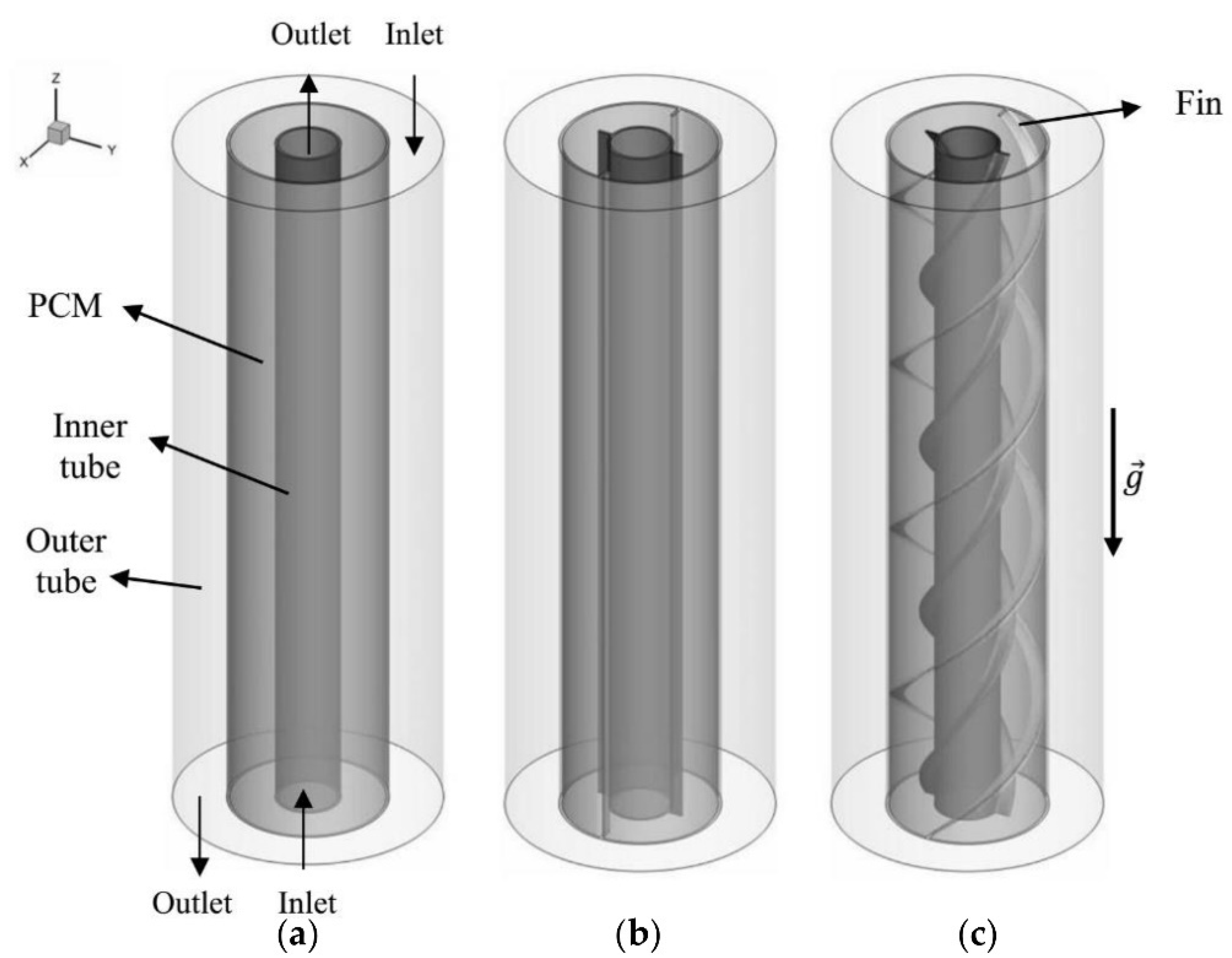
2. Problem Description
3. Mathematical Modeling
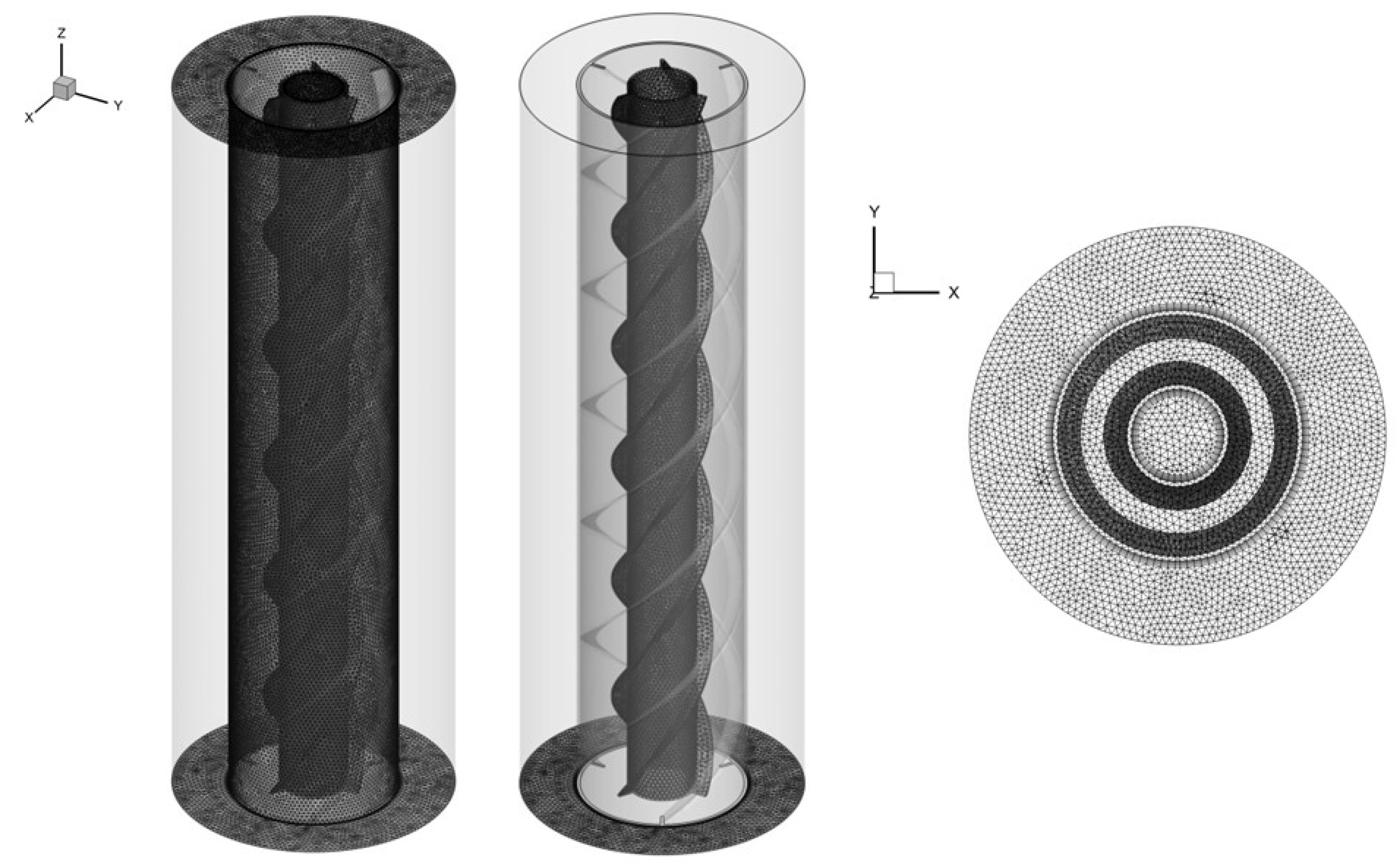
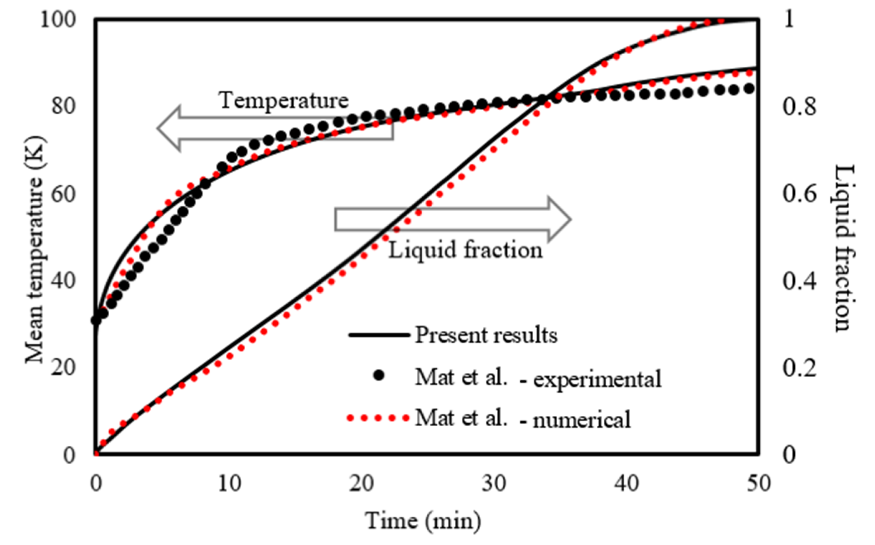
4. Numerical Process
5. Results and Discussion
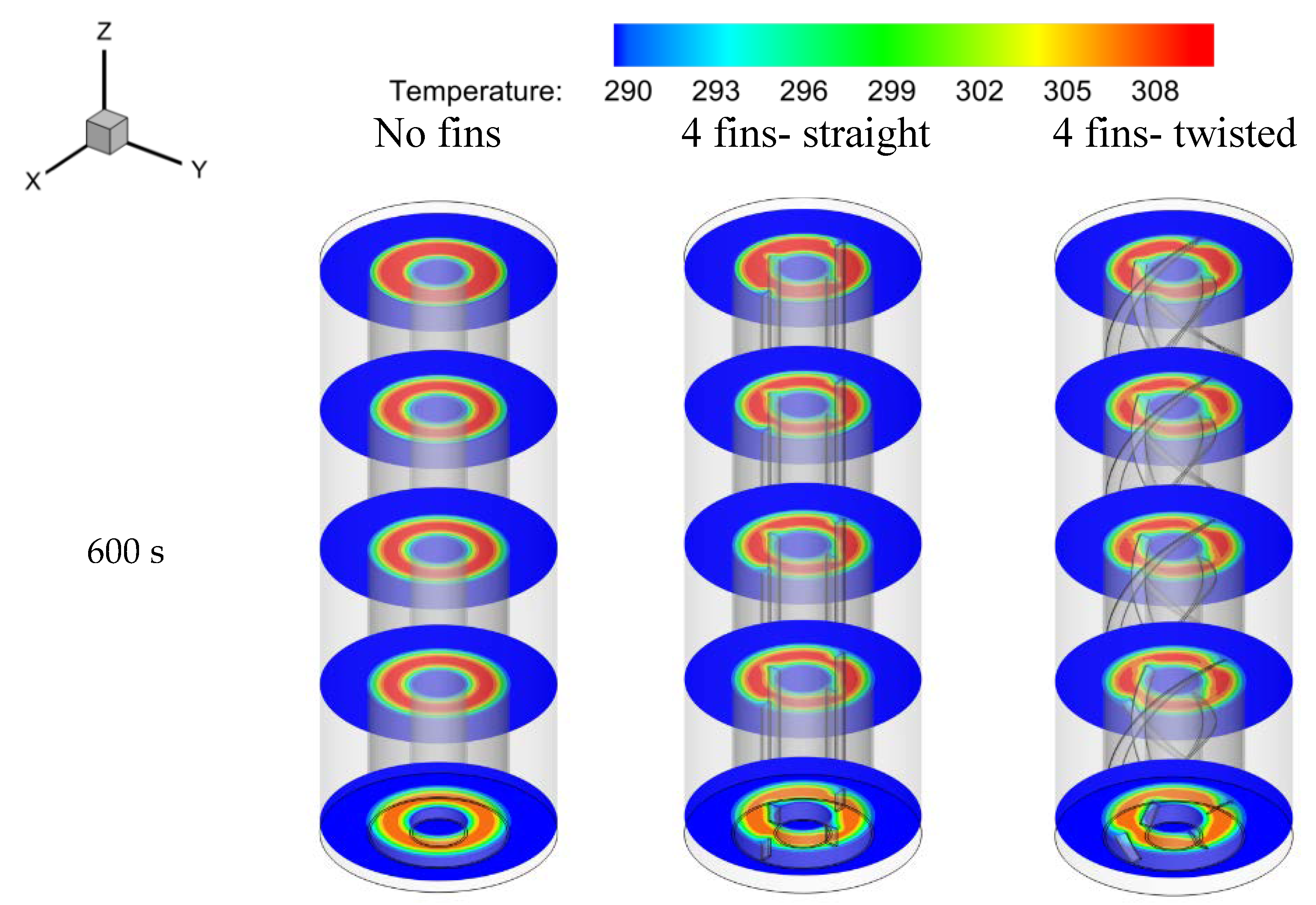
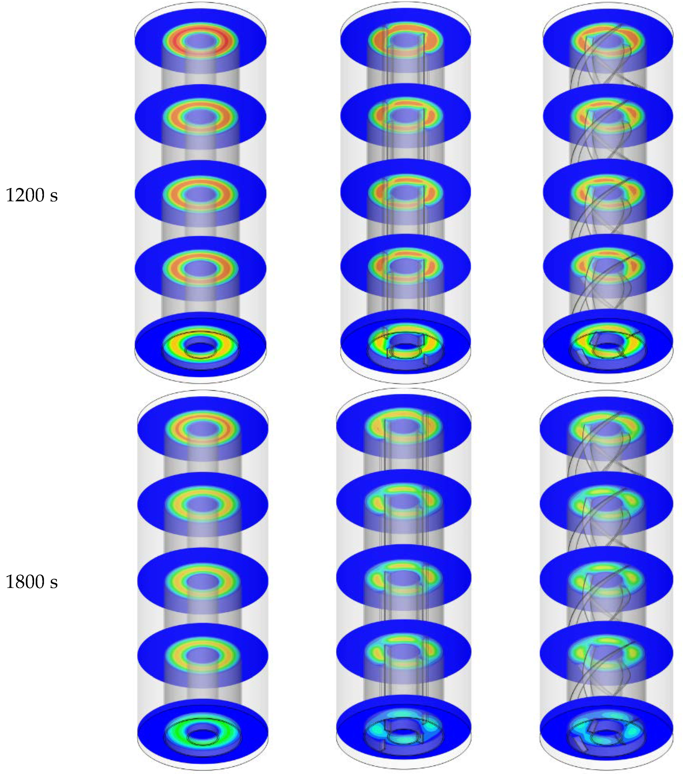
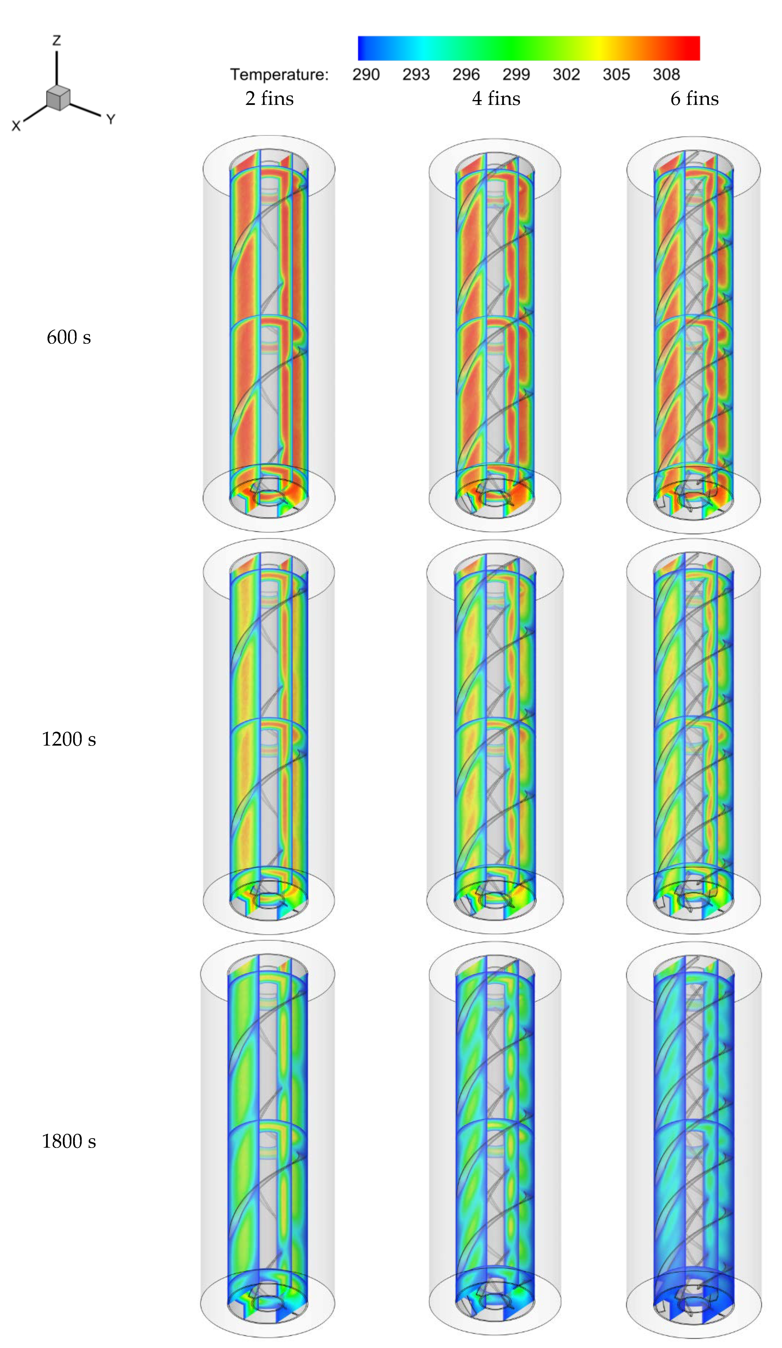
5.1. Evolution of the Temperature Field
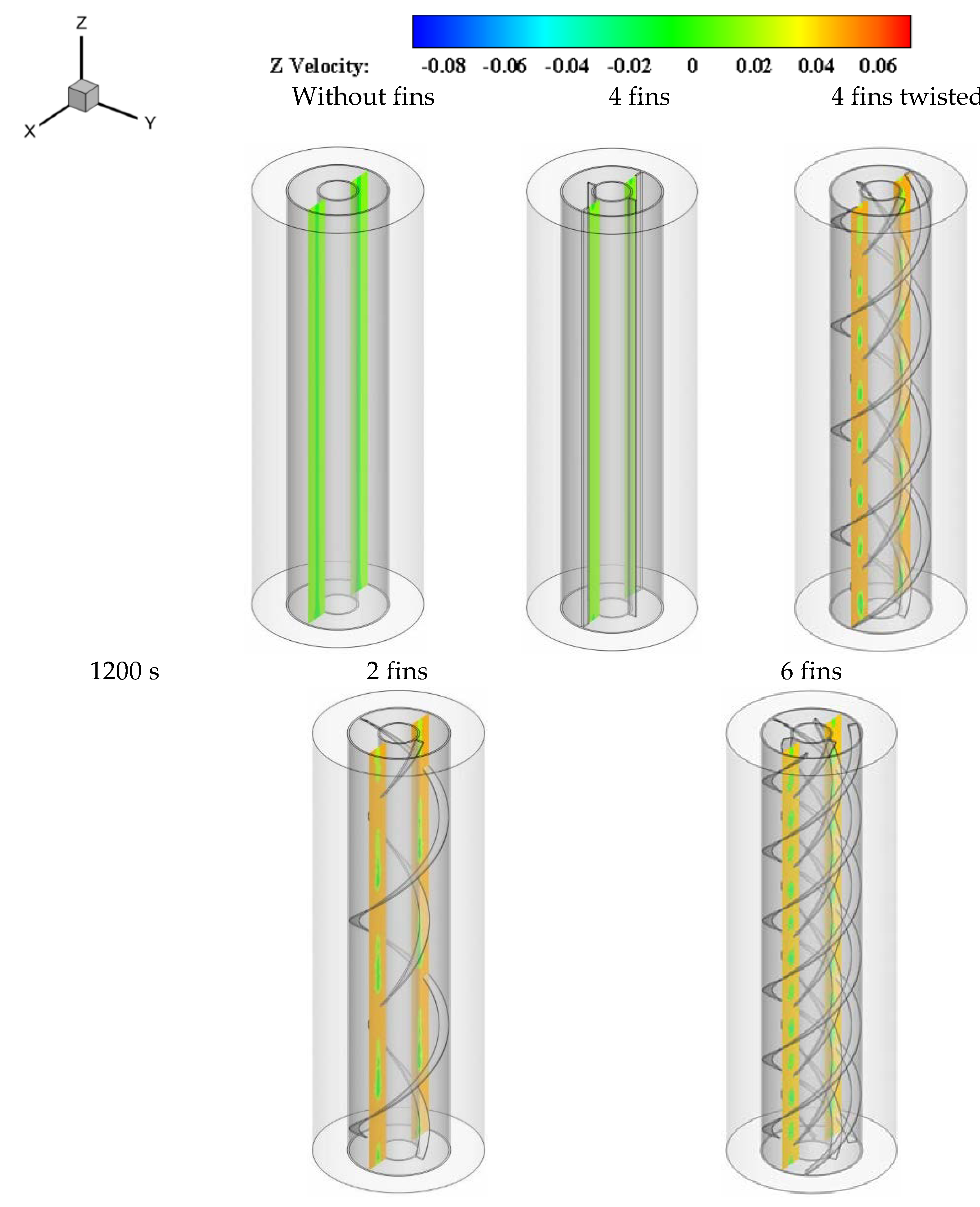
5.2. Evaluation of Velocity Distribution
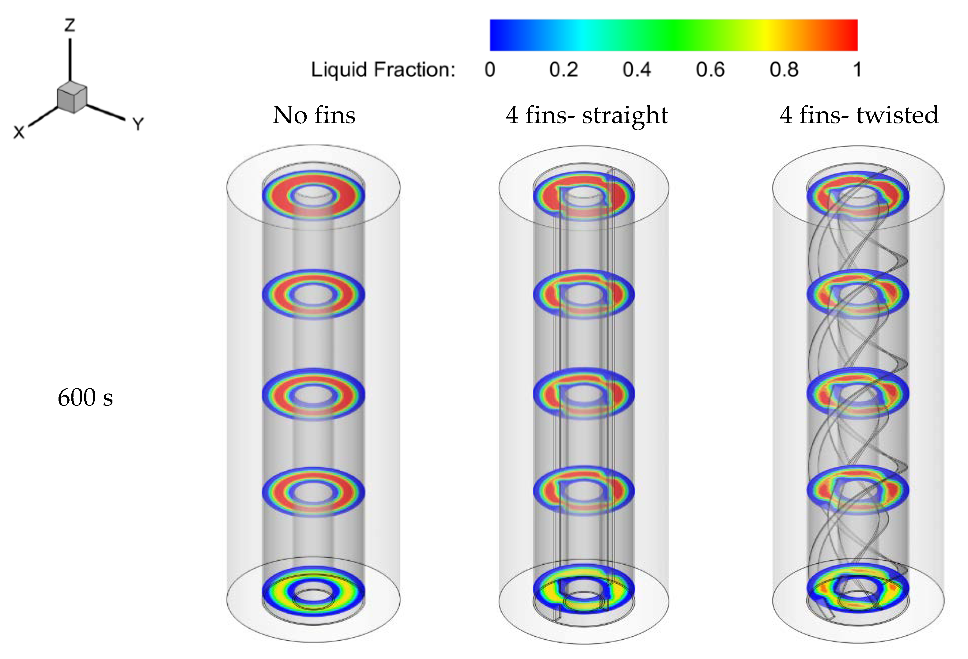
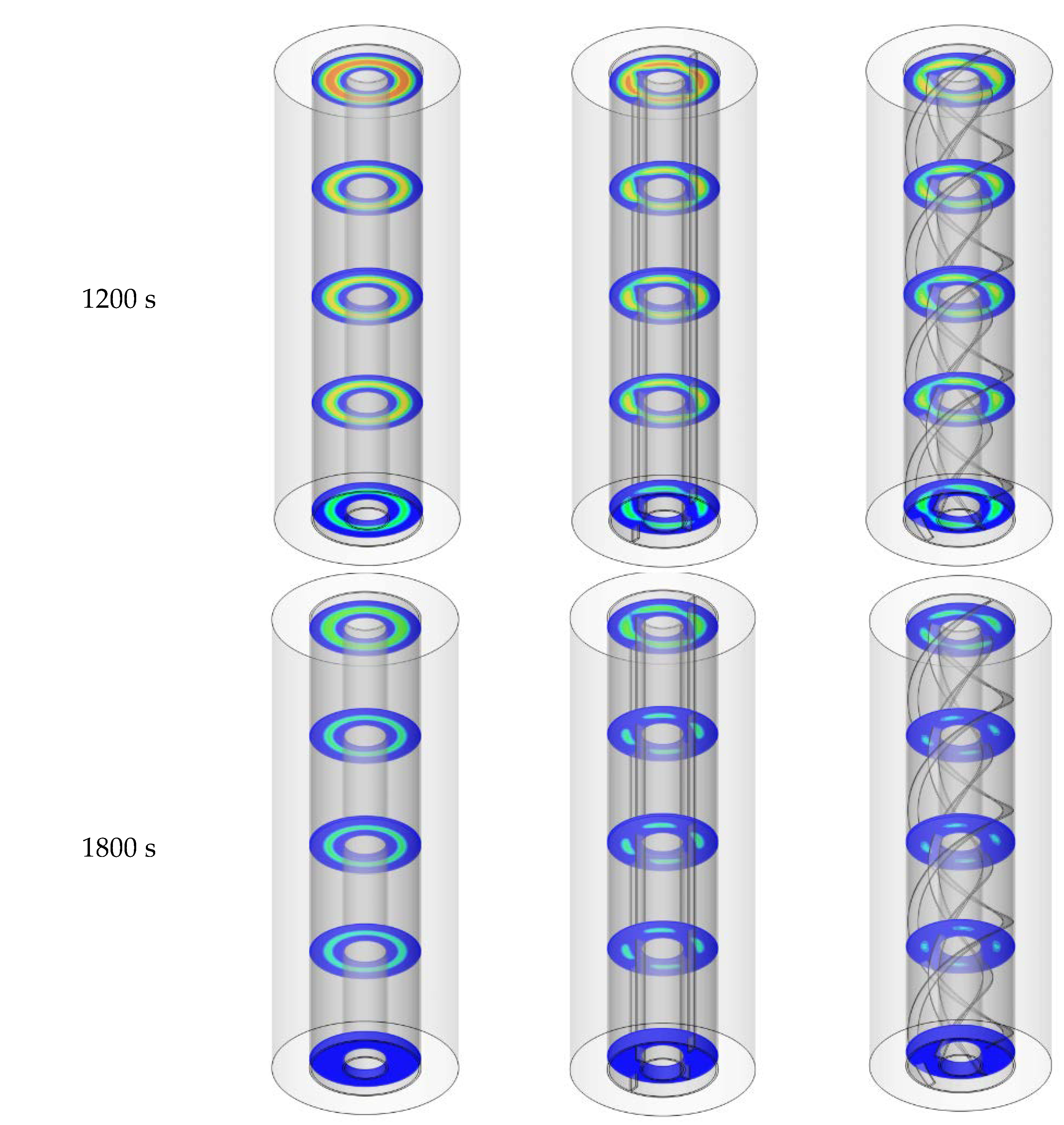
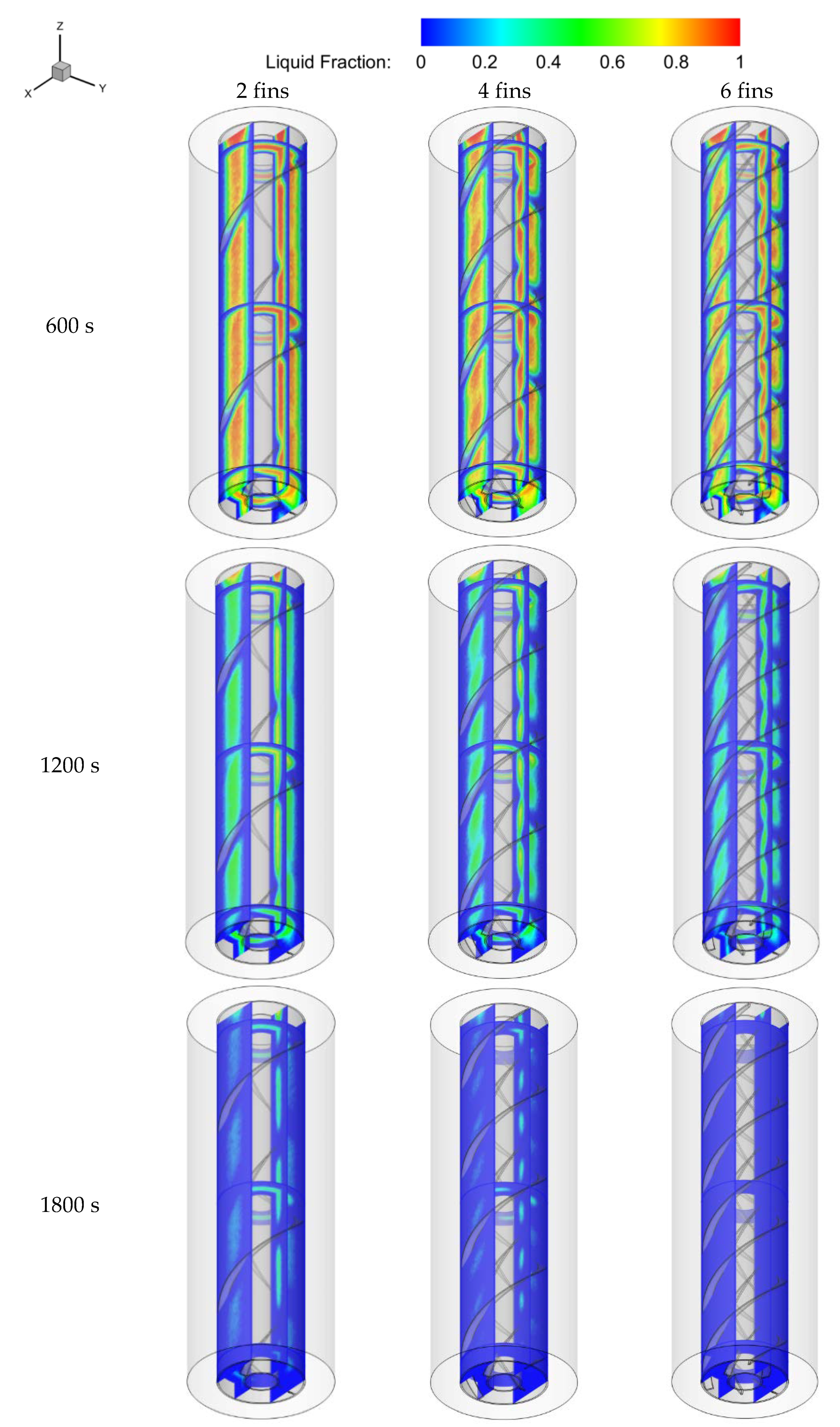
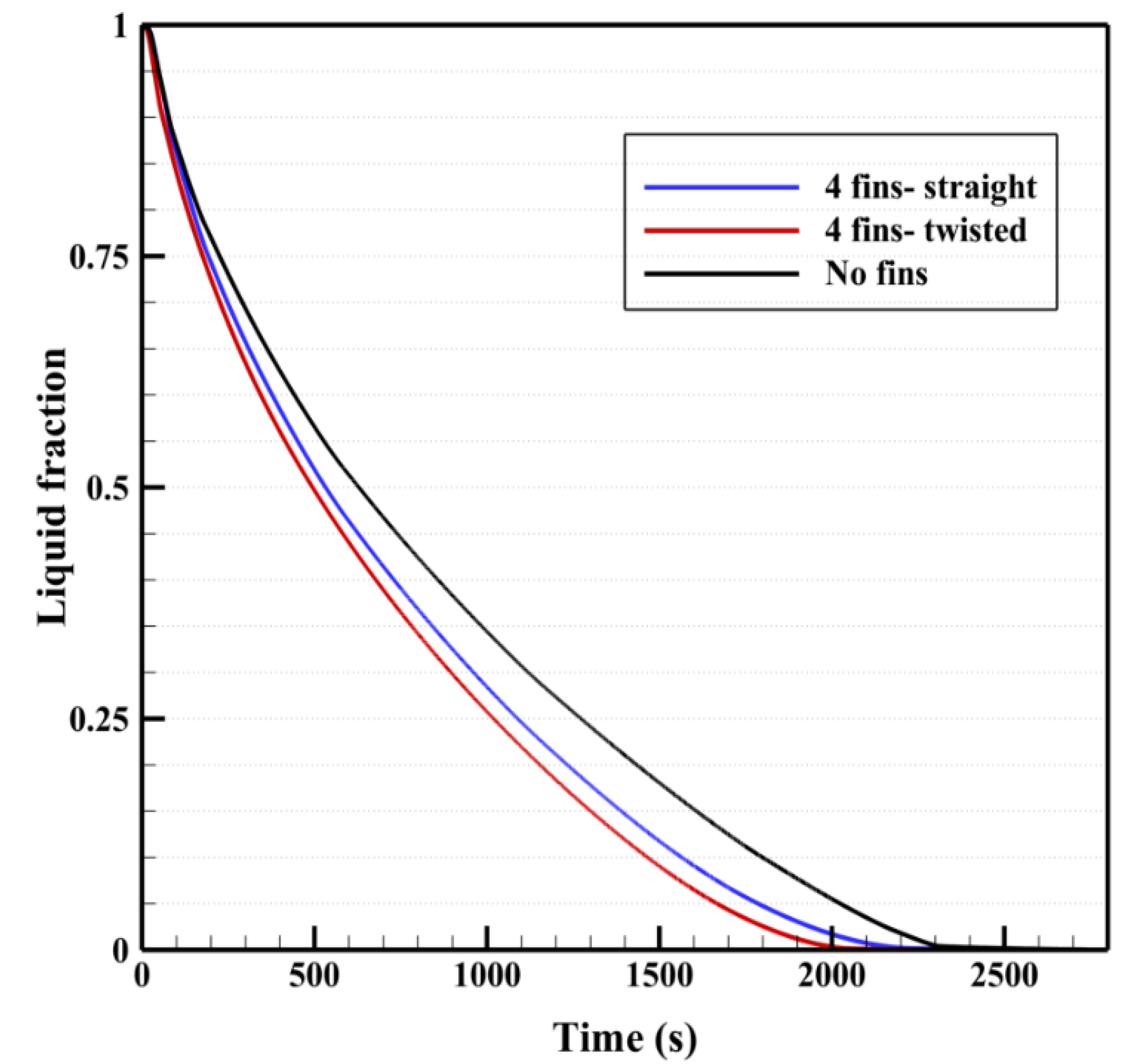
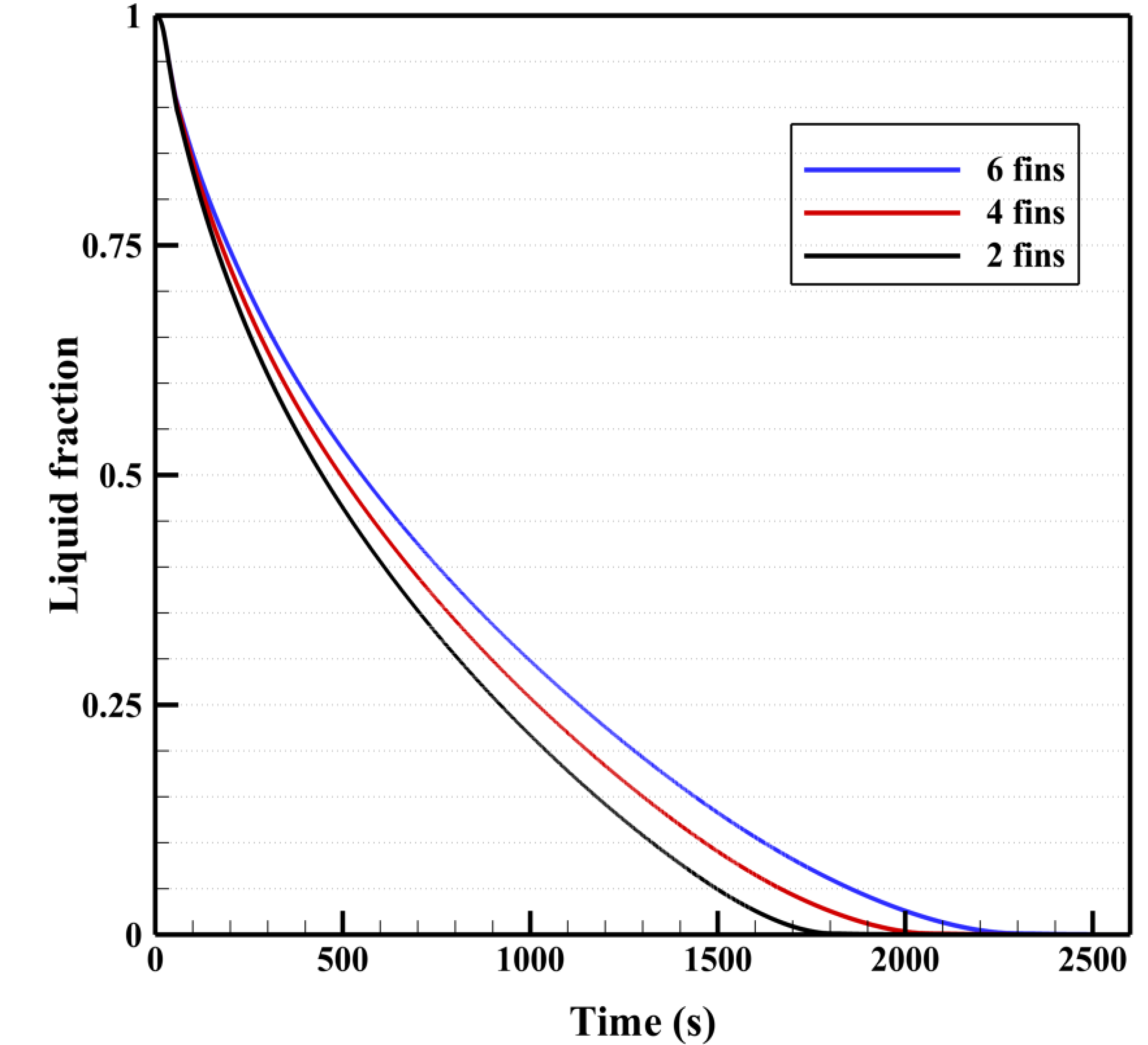
5.3. Evolution of the Liquid-Fraction Field
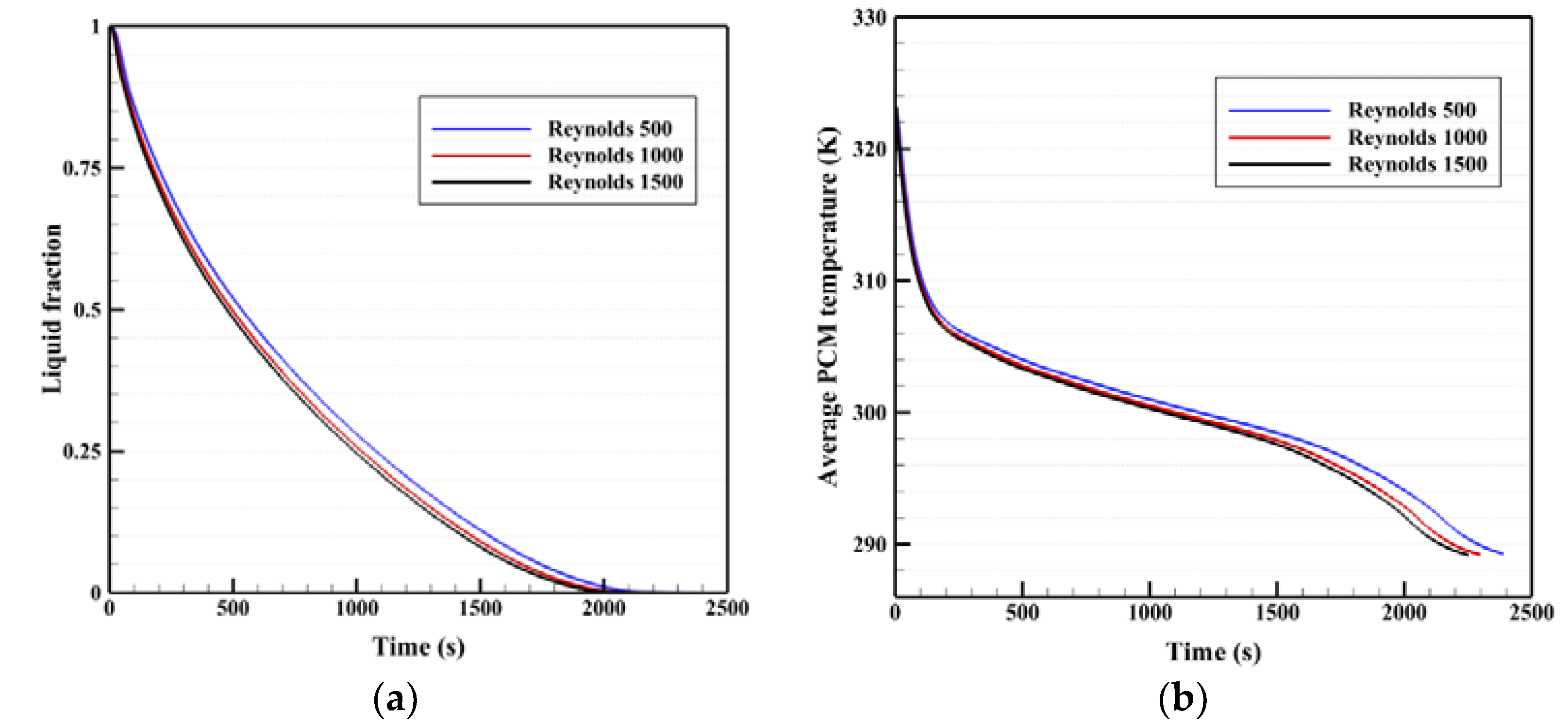
5.4. Impact of HTF Reynolds Number on Solidification of a PCM with Twisted Fins
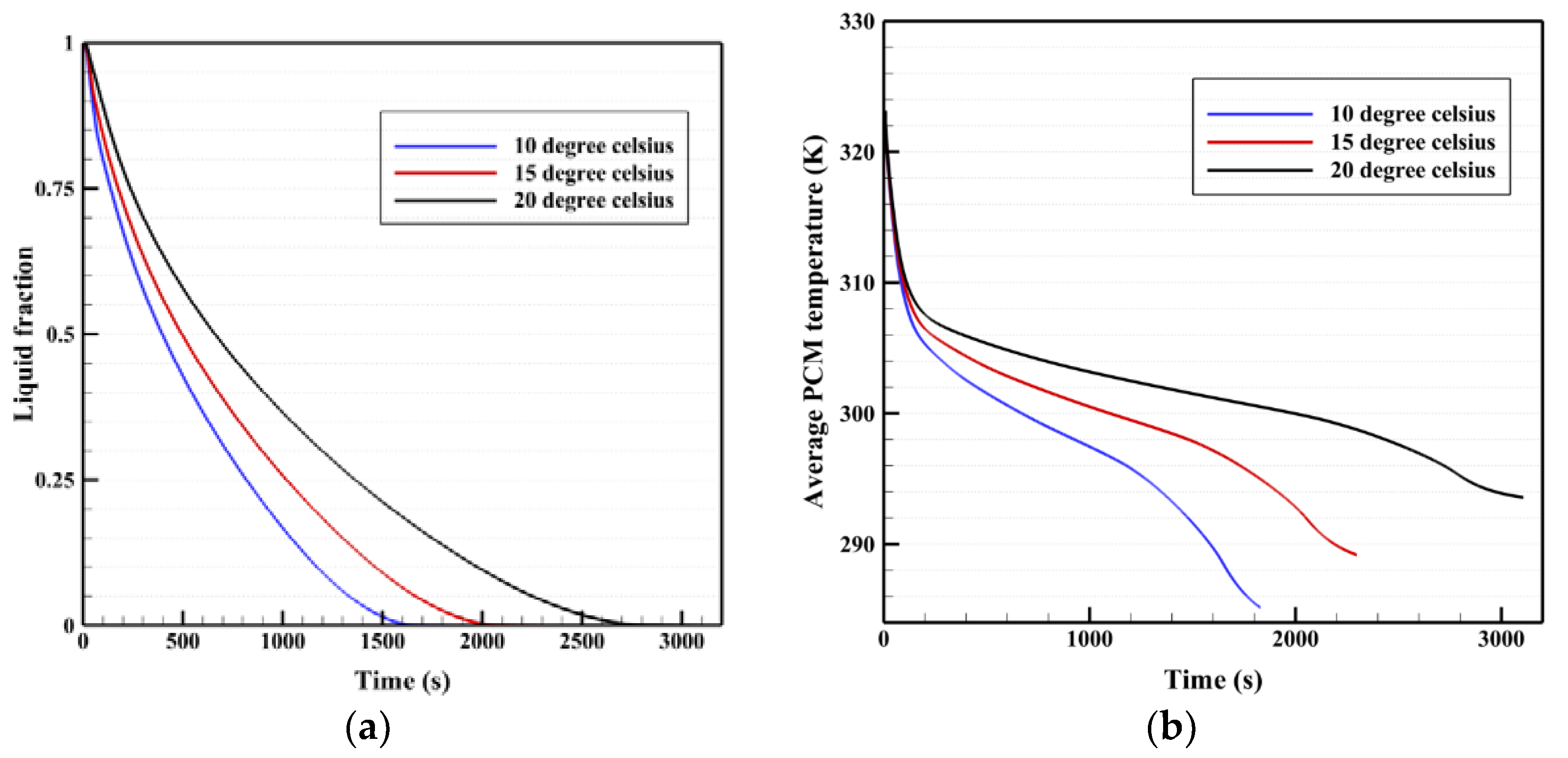
5.5. Impact of HTF Temperature on Solidification of a PCM with Twisted Fins
6. Conclusions
Author Contributions
Funding
Institutional Review Board Statement
Informed Consent Statement
Data Availability Statement
Conflicts of Interest
Nomenclature
| Nomenclature | |
| The mushy zone constant | |
| C | Inertial coefficient |
| PCM specific heat (J/kgK) | |
| D | Hydrolic diameter (m) |
| Gravitational acceleration (m/s2) | |
| thermal conductivity (W/mK) | |
| Latent heat of fusion (J/kg) | |
| PCM mass (kg) | |
| Pressure (Pa) | |
| Solidification rate (J) | |
| solidification time (s) | |
| Temperature (K) | |
| Melting point temperature (K) | |
| Velocity component (m/s) | |
| Velocity vector (m/s) | |
| Greek symbols | |
| Thermal expansion coefficient (1/K) | |
| Liquid fraction | |
| Thermal diffusivity (m2/s) | |
| Dynamic viscosity (kg/ms) | |
| Density (kg/m3) | |
References
- Wu, W.-F.; Liu, N.; Cheng, W.-L.; Liu, Y. Study on the effect of shape-stabilized phase change materials on spacecraft thermal control in extreme thermal environment. Energy Convers. Manag. 2013, 69, 174–180. [Google Scholar] [CrossRef]
- Guo, X.; Liu, J.; Dai, L.; Liu, Q.; Fang, D.; Wei, A.; Wang, J. Friction-wear failure mechanism of tubing strings used in high-pressure, high-temperature and high-yield gas wells. Wear 2021, 468, 203576. [Google Scholar] [CrossRef]
- Zhao, X.; Gu, B.; Gao, F.; Chen, S. Matching model of energy supply and demand of the integrated energy system in coastal areas. J. Coast. Res. 2020, 103, 983–989. [Google Scholar] [CrossRef]
- Mohammed, H.I.; Giddings, D.; Walker, G.S. CFD multiphase modelling of the acetone condensation and evaporation process in a horizontal circular tube. Int. J. Heat Mass Transf. 2019, 134, 1159–1170. [Google Scholar] [CrossRef]
- Zhang, L.; Zheng, H.; Wan, T.; Shi, D.; Lyu, L.; Cai, G. An integrated control algorithm of power distribution for islanded microgrid based on improved virtual synchronous generator. IET Renew. Power Gener. 2021, 15, 2674–2685. [Google Scholar] [CrossRef]
- Du, X.; Li, J.; Niu, G.; Yuan, J.-H.; Xue, K.-H.; Xia, M.; Pan, W.; Yang, X.; Zhu, B.; Tang, J. Lead halide perovskite for efficient optoacoustic conversion and application toward high-resolution ultrasound imaging. Nat. Commun. 2021, 12, 3348. [Google Scholar] [CrossRef]
- Dai, Z.; Xie, J.; Chen, Z.; Zhou, S.; Liu, J.; Liu, W.; Xi, Z.; Ren, X. Improved energy storage density and efficiency of (1−x) Ba0.85Ca0.15Zr0.1Ti0.9O3-xBiMg2/3Nb1/3O3 lead-free ceramics. Chem. Eng. J. 2021, 410, 128341. [Google Scholar] [CrossRef]
- Dai, Z.; Xie, J.; Fan, X.; Ding, X.; Liu, W.; Zhou, S.; Ren, X. Enhanced energy storage properties and stability of Sr(Sc0.5Nb0.5)O3 modified 0.65BaTiO3-0.35Bi0.5Na0.5TiO3 ceramics. Chem. Eng. J. 2020, 397, 125520. [Google Scholar] [CrossRef]
- Ghalambaz, M.; Mohammed, H.I.; Mahdi, J.M.; Eisapour, A.H.; Younis, O.; Ghosh, A.; Talebizadehsardari, P.; Yaïci, W. Intensifying the Charging Response of a Phase-Change Material with Twisted Fin Arrays in a Shell-And-Tube Storage System. Energies 2021, 14, 1619. [Google Scholar] [CrossRef]
- Yang, X.; Guo, J.; Yang, B.; Cheng, H.; Wei, P.; He, Y.-L. Design of non-uniformly distributed annular fins for a shell-and-tube thermal energy storage unit. Appl. Energy 2020, 279, 115772. [Google Scholar] [CrossRef]
- Zhang, B.; Xu, D.; Liu, Y.; Li, F.; Cai, J.; Du, L. Multi-scale evapotranspiration of summer maize and the controlling meteorological factors in north China. Agric. For. Meteorol. 2016, 216, 1–12. [Google Scholar] [CrossRef]
- Berardi, U.; Soudian, S. Benefits of latent thermal energy storage in the retrofit of Canadian high-rise residential buildings. Build. Simul. 2018, 11, 709–723. [Google Scholar] [CrossRef]
- Sun, L.; Li, C.; Zhang, C.; Su, Z.; Chen, C. Early monitoring of rebar corrosion evolution based on FBG sensor. Int. J. Struct. Stab. Dyn. 2018, 18, 1840001. [Google Scholar] [CrossRef]
- Mahdi, J.M.; Mohammed, H.I.; Talebizadehsardari, P. A new approach for employing multiple PCMs in the passive thermal management of photovoltaic modules. Sol. Energy 2021, 222, 160–174. [Google Scholar] [CrossRef]
- Qureshi, Z.A.; Ali, H.M.; Khushnood, S. Recent advances on thermal conductivity enhancement of phase change materials for energy storage system: A review. Int. J. Heat Mass Transf. 2018, 127, 838–856. [Google Scholar] [CrossRef]
- Yang, X.; Wei, P.; Wang, X.; He, Y.-L. Gradient design of pore parameters on the melting process in a thermal energy storage unit filled with open-cell metal foam. Appl. Energy 2020, 268, 115019. [Google Scholar] [CrossRef]
- Xu, Q.; Wang, K.; Zou, Z.; Zhong, L.; Akkurt, N.; Feng, J.; Xiong, Y.; Han, J.; Wang, J.; Du, Y. A new type of two-supply, one-return, triple pipe-structured heat loss model based on a low temperature district heating system. Energy 2021, 218, 119569. [Google Scholar] [CrossRef]
- Mehryan, S.A.M.; Ghalambaz, M.; Sasani Gargari, L.; Hajjar, A.; Sheremet, M. Natural convection flow of a suspension containing nano-encapsulated phase change particles in an eccentric annulus. J. Energy Storage 2020, 28, 101236. [Google Scholar] [CrossRef]
- Abdulateef, A.M.; Abdulateef, J.; Al-Abidi, A.A.; Sopian, K.; Mat, S.; Mahdi, M.S. A combination of fins-nanoparticle for enhancing the discharging of phase-change material used for liquid desiccant air conditioning unite. J. Energy Storage 2019, 24, 100784. [Google Scholar] [CrossRef]
- Mahani, R.B.; Mohammed, H.I.; Mahdi, J.M.; Alamshahi, F.; Ghalambaz, M.; Talebizadehsardari, P.; Yaïci, W. Phase Change Process in a Zigzag Plate Latent Heat Storage System during Melting and Solidification. Molecules 2020, 25, 4643. [Google Scholar] [CrossRef]
- Shanan, Z.J.; Hadi, S.M.; Shanshool, S.K. Structural Analysis of Chemical and Green Synthesis of CuO Nanoparticles and their Effect on Biofilm Formation. Baghdad Sci. J. 2018, 15, 0211. [Google Scholar] [CrossRef]
- Mahdi, J.M.; Nsofor, E.C. Solidification of a PCM with nanoparticles in triplex-tube thermal energy storage system. Appl. Therm. Eng. 2016, 108, 596–604. [Google Scholar] [CrossRef]
- Al-Jethelah, M.; Tasnim, S.H.; Mahmud, S.; Dutta, A. Nano-PCM filled energy storage system for solar-thermal applications. Renew. Energy 2018, 126, 137–155. [Google Scholar] [CrossRef]
- Liao, Z.; Xu, C.; Ren, Y.; Gao, F.; Ju, X.; Du, X. A novel effective thermal conductivity correlation of the PCM melting in spherical PCM encapsulation for the packed bed TES system. Appl. Therm. Eng. 2018, 135, 116–122. [Google Scholar] [CrossRef]
- Mahdi, J.M.; Mohammed, H.I.; Hashim, E.T.; Talebizadehsardari, P.; Nsofor, E.C. Solidification enhancement with multiple PCMs, cascaded metal foam and nanoparticles in the shell-and-tube energy storage system. Appl. Energy 2020, 257, 113993. [Google Scholar] [CrossRef]
- Eisapour, M.; Eisapour, A.H.; Hosseini, M.J.; Talebizadehsardari, P. Exergy and energy analysis of wavy tubes photovoltaic-thermal systems using microencapsulated PCM nano-slurry coolant fluid. Appl. Energy 2020, 266, 114849. [Google Scholar] [CrossRef]
- Ghalambaz, M.; Mehryan, S.; Hajjar, A.; Veismoradi, A. Unsteady natural convection flow of a suspension comprising Nano-Encapsulated Phase Change Materials (NEPCMs) in a porous medium. Adv. Powder Technol. 2020, 31, 954–966. [Google Scholar] [CrossRef]
- Talebizadeh Sardari, P.; Mohammed, H.I.; Mahdi, J.M.; Ghalambaz, M.; Gillott, M.; Walker, G.S.; Grant, D.; Giddings, D. Localized heating element distribution in composite metal foam-phase change material: Fourier’s law and creeping flow effects. Int. J. Energy Res. 2021, 45, 13380–13396. [Google Scholar] [CrossRef]
- Ghalambaz, M.; Mohammed, H.I.; Naghizadeh, A.; Islam, M.S.; Younis, O.; Mahdi, J.M.; Chatroudi, I.S.; Talebizadehsardari, P. Optimum Placement of Heating Tubes in a Multi-Tube Latent Heat Thermal Energy Storage. Materials 2021, 14, 1232. [Google Scholar] [CrossRef]
- Talebizadehsardari, P.; Mohammed, H.I.; Mahdi, J.M.; Gillott, M.; Walker, G.S.; Grant, D.; Giddings, D. Effect of airflow channel arrangement on the discharge of a composite metal foam-phase change material heat exchanger. Int. J. Energy Res. 2021, 45, 2593–2609. [Google Scholar] [CrossRef]
- Ju, Y.; Zhu, T.; Mashayekhi, R.; Mohammed, H.I.; Khan, A.; Talebizadehsardari, P.; Yaïci, W. Evaluation of Multiple Semi-Twisted Tape Inserts in a Heat Exchanger Pipe Using Al2O3 Nanofluid. Nanomaterials 2021, 11, 1570. [Google Scholar] [CrossRef]
- Mahdi, J.M.; Nsofor, E.C. Melting enhancement in triplex-tube latent thermal energy storage system using nanoparticles-fins combination. Int. J. Heat Mass Transf. 2017, 109, 417–427. [Google Scholar] [CrossRef]
- Sheikholeslami, M.; Lohrasbi, S.; Ganji, D.D. Numerical analysis of discharging process acceleration in LHTESS by immersing innovative fin configuration using finite element method. Appl. Therm. Eng. 2016, 107, 154–166. [Google Scholar] [CrossRef]
- Mohammed, H.I.; Talebizadehsardari, P.; Mahdi, J.M.; Arshad, A.; Sciacovelli, A.; Giddings, D. Improved melting of latent heat storage via porous medium and uniform Joule heat generation. J. Energy Storage 2020, 31, 101747. [Google Scholar] [CrossRef]
- Dai, Z.; Guo, S.; Gong, Y.; Wang, Z. Semiconductor flexoelectricity in graphite-doped SrTiO3 ceramics. Ceram. Int. 2021, 47, 6535–6539. [Google Scholar] [CrossRef]
- Sun, J.; Aslani, F.; Wei, J.; Wang, X. Electromagnetic absorption of copper fiber oriented composite using 3D printing. Constr. Build. Mater. 2021, 300, 124026. [Google Scholar] [CrossRef]
- Ghalambaz, M.; Zadeh, S.M.H.; Mehryan, S.; Pop, I.; Wen, D. Analysis of melting behavior of PCMs in a cavity subject to a non-uniform magnetic field using a moving grid technique. Appl. Math. Model. 2020, 77, 1936–1953. [Google Scholar] [CrossRef]
- Ghalambaz, M.; Zadeh, S.M.H.; Mehryan, S.; Ayoubloo, K.A.; Sedaghatizadeh, N. Non-Newtonian behavior of an electrical and magnetizable phase change material in a filled enclosure in the presence of a non-uniform magnetic field. Int. Commun. Heat Mass Transf. 2020, 110, 104437. [Google Scholar] [CrossRef]
- Jiang, T.; Liu, Z.; Wang, G.; Chen, Z. Comparative study of thermally stratified tank using different heat transfer materials for concentrated solar power plant. Energy Rep. 2021, 7, 3678–3687. [Google Scholar] [CrossRef]
- Tao, L.C. Generalized numerical solutions of freezing a saturated liquid in cylinders and spheres. AIChE J. 1967, 13, 165–169. [Google Scholar] [CrossRef]
- Gortych, M.; Lipnicki, Z.; Weigand, B. An experimental and theoretical study of the solidification process of phase change materials in a horizontal annular enclosure. Appl. Therm. Eng. 2019, 161, 114140. [Google Scholar] [CrossRef]
- Abdollahzadeh, M.; Esmaeilpour, M. Enhancement of phase change material (PCM) based latent heat storage system with nano fluid and wavy surface. Int. J. Heat Mass Transf. 2015, 80, 376–385. [Google Scholar] [CrossRef]
- Shahsavar, A.; Al-Rashed, A.A.A.A.; Entezari, S.; Sardari, P.T. Melting and solidification characteristics of a double-pipe latent heat storage system with sinusoidal wavy channels embedded in a porous medium. Energy 2019, 171, 751–769. [Google Scholar] [CrossRef]
- Choi, J.C.; Kim, S.D. Heat-transfer characteristics of a latent heat storage system using MgCl2·6H2O. Energy 1992, 17, 1153–1164. [Google Scholar] [CrossRef]
- Wang, P.; Li, D.; Huang, Y.; Zheng, X.; Wang, Y.; Peng, Z.; Ding, Y. Numerical Study of Solidification in a Plate Heat Exchange Device with a Zigzag Configuration Containing Multiple Phase-Change-Materials. Energies 2016, 9, 394. [Google Scholar] [CrossRef] [Green Version]
- Talebizadehsardari, P.; Mahdi, J.M.; Mohammed, H.I.; Moghimi, M.A.; Hossein Eisapour, A.; Ghalambaz, M. Consecutive charging and discharging of a PCM-based plate heat exchanger with zigzag configuration. Appl. Therm. Eng. 2021, 193, 116970. [Google Scholar] [CrossRef]
- Li, H.; Xu, B.; Lu, G.; Du, C.; Huang, N. Multi-objective optimization of PEM fuel cell by coupled significant variables recognition, surrogate models and a multi-objective genetic algorithm. Energy Convers. Manag. 2021, 236, 114063. [Google Scholar] [CrossRef]
- Li, H.-W.; Gao, Y.-F.; Du, C.-H.; Hong, W.-P. Numerical study on swirl cooling flow, heat transfer and stress characteristics based on fluid-structure coupling method under different swirl chamber heights and Reynolds numbers. Int. J. Heat Mass Transf. 2021, 173, 121228. [Google Scholar] [CrossRef]
- Shokouhmand, H.; Kamkari, B. Numerical Simulation of Phase Change Thermal Storage in Finned Double-Pipe Heat Exchanger. Appl. Mech. Mater. 2012, 232, 742–746. [Google Scholar] [CrossRef]
- Bazai, H.; Moghimi, M.A.; Mohammed, H.I.; Babaei-Mahani, R.; Talebizadehsardari, P. Numerical study of circular-elliptical double-pipe thermal energy storage systems. J. Energy Storage 2020, 30, 101440. [Google Scholar] [CrossRef]
- Shahsavar, A.; Ali, H.M.; Mahani, R.B.; Talebizadehsardari, P. Numerical study of melting and solidification in a wavy double-pipe latent heat thermal energy storage system. J. Therm. Anal. Calorim. 2020, 141, 1785–1799. [Google Scholar] [CrossRef]
- Shahsavar, A.; Khosravi, J.; Mohammed, H.I.; Talebizadehsardari, P. Performance evaluation of melting/solidification mechanism in a variable wave-length wavy channel double-tube latent heat storage system. J. Energy Storage 2020, 27, 101063. [Google Scholar] [CrossRef]
- Xu, Y.; Ren, Q.; Zheng, Z.-J.; He, Y.-L. Evaluation and optimization of melting performance for a latent heat thermal energy storage unit partially filled with porous media. Appl. Energy 2017, 193, 84–95. [Google Scholar] [CrossRef]
- Xu, Y.; Li, M.-J.; Zheng, Z.-J.; Xue, X.-D. Melting performance enhancement of phase change material by a limited amount of metal foam: Configurational optimization and economic assessment. Appl. Energy 2018, 212, 868–880. [Google Scholar] [CrossRef]
- Ghalambaz, M.; Mahdi, J.M.; Shafaghat, A.; Eisapour, A.H.; Younis, O.; Talebizadeh Sardari, P.; Yaïci, W. Effect of Twisted Fin Array in a Triple-Tube Latent Heat Storage System during the Charging Mode. Sustainability 2021, 13, 2685. [Google Scholar] [CrossRef]
- Mahdi, J.M.; Lohrasbi, S.; Ganji, D.D.; Nsofor, E.C. Accelerated melting of PCM in energy storage systems via novel configuration of fins in the triplex-tube heat exchanger. Int. J. Heat Mass Transf. 2018, 124, 663–676. [Google Scholar] [CrossRef]
- Mahdi, J.M.; Nsofor, E.C. Melting enhancement in triplex-tube latent heat energy storage system using nanoparticles-metal foam combination. Appl. Energy 2017, 191, 22–34. [Google Scholar] [CrossRef]
- Li, Z.; Shahsavar, A.; Al-Rashed, A.A.A.A.; Talebizadehsardari, P. Effect of porous medium and nanoparticles presences in a counter-current triple-tube composite porous/nano-PCM system. Appl. Therm. Eng. 2020, 167, 114777. [Google Scholar] [CrossRef]
- Abdulateef, A.M.; Mat, S.; Abdulateef, J.; Sopian, K.; Al-Abidi, A.A. Geometric and design parameters of fins employed for enhancing thermal energy storage systems: A review. Renew. Sustain. Energy Rev. 2018, 82, 1620–1635. [Google Scholar] [CrossRef]
- Mat, S.; Al-Abidi, A.A.; Sopian, K.; Sulaiman, M.Y.; Mohammad, A.T. Enhance heat transfer for PCM melting in triplex tube with internal–external fins. Energy Convers. Manag. 2013, 74, 223–236. [Google Scholar] [CrossRef]
- Rabienataj Darzi, A.A.; Jourabian, M.; Farhadi, M. Melting and solidification of PCM enhanced by radial conductive fins and nanoparticles in cylindrical annulus. Energy Convers. Manag. 2016, 118, 253–263. [Google Scholar] [CrossRef]
- Pizzolato, A.; Sharma, A.; Maute, K.; Sciacovelli, A.; Verda, V. Design of effective fins for fast PCM melting and solidification in shell-and-tube latent heat thermal energy storage through topology optimization. Appl. Energy 2017, 208, 210–227. [Google Scholar] [CrossRef]
- Yıldız, Ç.; Arıcı, M.; Nižetić, S.; Shahsavar, A. Numerical investigation of natural convection behavior of molten PCM in an enclosure having rectangular and tree-like branching fins. Energy 2020, 207, 118223. [Google Scholar] [CrossRef]
- Yu, C.; Wu, S.; Huang, Y.; Yao, F.; Liu, X. Charging performance optimization of a latent heat storage unit with fractal tree-like fins. J. Energy Storage 2020, 30, 101498. [Google Scholar] [CrossRef]
- Rathod, M.K.; Banerjee, J. Thermal performance enhancement of shell and tube Latent Heat Storage Unit using longitudinal fins. Appl. Therm. Eng. 2015, 75, 1084–1092. [Google Scholar] [CrossRef]
- Abdulateef, A.M.; Mat, S.; Sopian, K.; Abdulateef, J.; Gitan, A.A. Experimental and computational study of melting phase-change material in a triplex tube heat exchanger with longitudinal/triangular fins. Sol. Energy 2017, 155, 142–153. [Google Scholar] [CrossRef]
- Shahsavar, A.; Goodarzi, A.; Mohammed, H.I.; Shirneshan, A.; Talebizadehsardari, P. Thermal performance evaluation of non-uniform fin array in a finned double-pipe latent heat storage system. Energy 2020, 193, 116800. [Google Scholar] [CrossRef]
- Maakoul, A.E.; Laknizi, A.; Saadeddine, S.; Abdellah, A.B.; Meziane, M.; Metoui, M.E. Numerical design and investigation of heat transfer enhancement and performance for an annulus with continuous helical baffles in a double-pipe heat exchanger. Energy Convers. Manag. 2017, 133, 76–86. [Google Scholar] [CrossRef]
- Maakoul, A.E.; Metoui, M.E.; Abdellah, A.B.; Saadeddine, S.; Meziane, M. Numerical investigation of thermohydraulic performance of air to water double-pipe heat exchanger with helical fins. Appl. Therm. Eng. 2017, 127, 127–139. [Google Scholar] [CrossRef]
- Rubitherm Technologies GmbH. RT35 Data Sheet. Available online: https://www.rubitherm.eu/media/products/datasheets/Techdata_-RT35_EN_09102020.PDF (accessed on 15 September 2021).
- Talebizadeh Sardari, P.; Walker, G.S.; Gillott, M.; Grant, D.; Giddings, D. Numerical modelling of phase change material melting process embedded in porous media: Effect of heat storage size. Proc. Inst. Mech. Eng. Part A J. Power Energy 2019, 0957650919862974. [Google Scholar] [CrossRef]
- Shahsavar, A.; Majidzadeh, A.H.; Mahani, R.B.; Talebizadehsardari, P. Entropy and Thermal performance Analysis of PCM Melting and Solidification Mechanisms in a Wavy Channel Triplex-Tube Heat Exchanger. Renew. Energy 2021, 165, 52–72. [Google Scholar] [CrossRef]
- Al-Abidi, A.A.; Mat, S.; Sopian, K.; Sulaiman, M.Y.; Mohammad, A.T. Internal and external fin heat transfer enhancement technique for latent heat thermal energy storage in triplex tube heat exchangers. Appl. Therm. Eng. 2013, 53, 147–156. [Google Scholar] [CrossRef]
- Mahdi, J.M. Enhancement of Phase Change Material (PCM) Thermal Energy Storage in Triplex-Tube Systems. Ph.D. Thesis, Southern Illinois University Carbondale, Carbondale, IL, USA, 2018. [Google Scholar]


| Property | RT35 |
|---|---|
| Specific heat (kJ/kg K) | 2 |
| Viscosity (Pa s) | 0.023 |
| Heat of fusion (kJ/kg) | 170 |
| Liquidus temperature (°C) | 35 |
| Density (kg/m3) | 815 |
| Thermal conductivity (W/m K) | 0.2 |
| Solidus temperature (°C) | 29 |
| Thermal expansion coefficient (1/K) | 0.0006 |
| Fins | Solidifying Time (s) | Discharging Rate (W) |
|---|---|---|
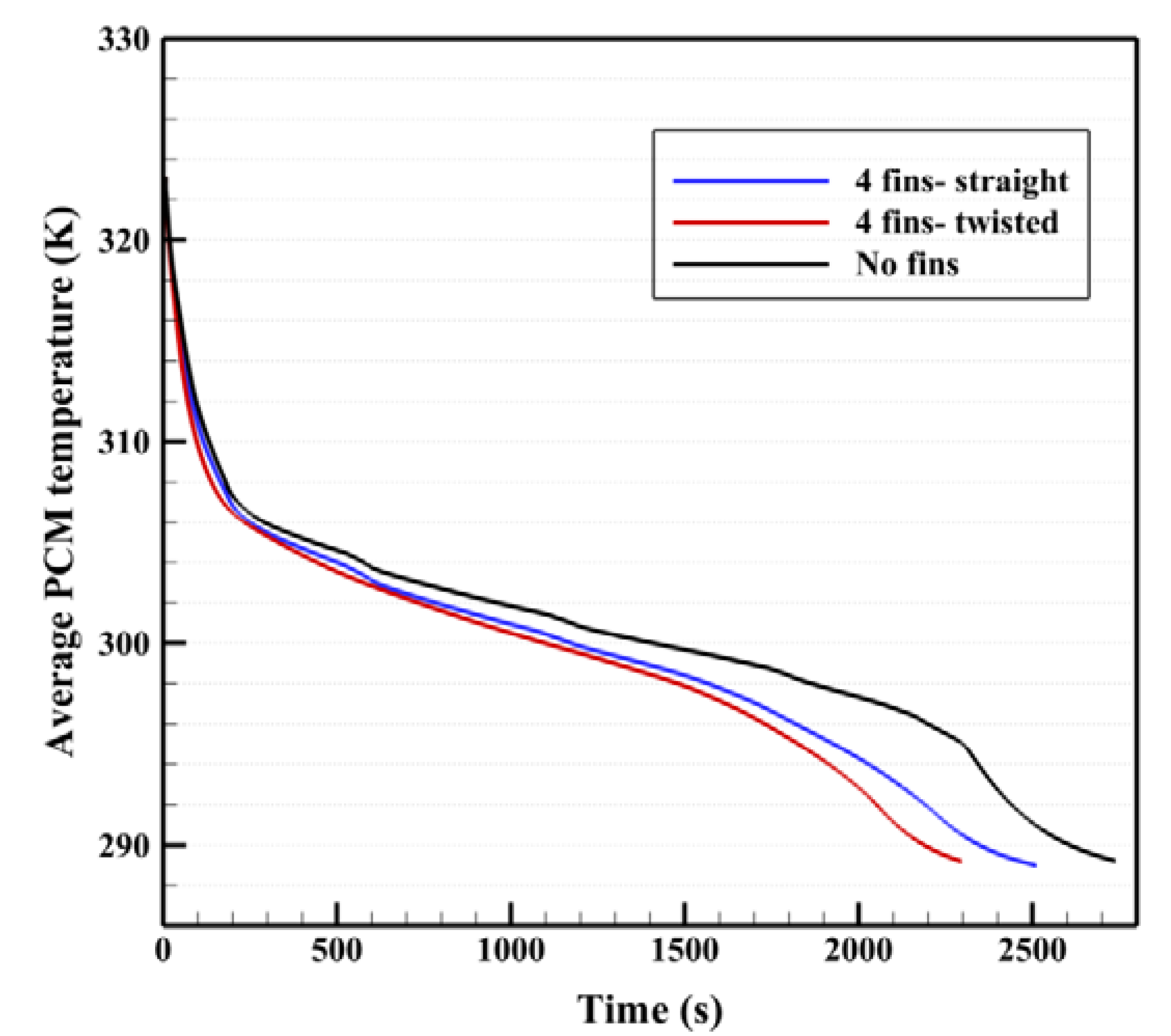
| No fins | 2739 | 27.87 |
| Straight fins | 2512 | 30.45 |
| Four twisted fins | 2229 | 34.25 |
| Fins | Solidifying Time (s) | Discharging Rate (W) |
|---|---|---|
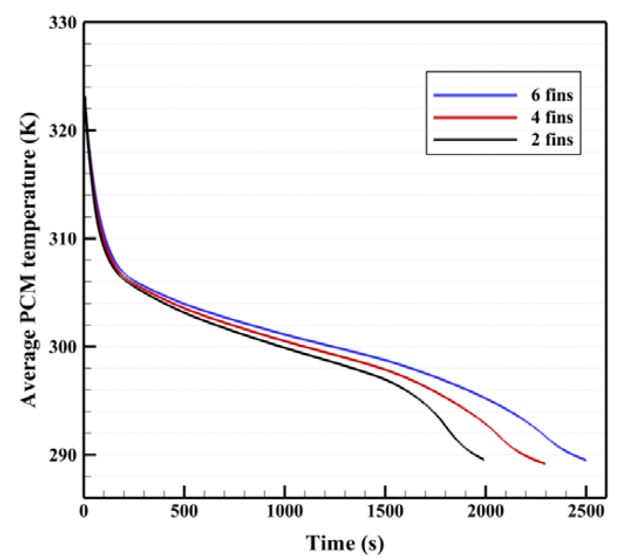
| 2 fins | 2502 | 30.45 |
| 4 fins | 2229 | 34.25 |
| 6 fins | 1992 | 38.20 |
| No-Fins | Straight Fins | 2 Fins | 4 Fins | 6 Fins | |
|---|---|---|---|---|---|
| Dimensionless time | 0.016804 | 0.015411 | 0.01535 | 0.013675 | 0.012221 |
Publisher’s Note: MDPI stays neutral with regard to jurisdictional claims in published maps and institutional affiliations. |
© 2021 by the authors. Licensee MDPI, Basel, Switzerland. This article is an open access article distributed under the terms and conditions of the Creative Commons Attribution (CC BY) license (https://creativecommons.org/licenses/by/4.0/).
Share and Cite
Sun, X.; Mahdi, J.M.; Mohammed, H.I.; Majdi, H.S.; Zixiong, W.; Talebizadehsardari, P. Solidification Enhancement in a Triple-Tube Latent Heat Energy Storage System Using Twisted Fins. Energies 2021, 14, 7179. https://doi.org/10.3390/en14217179
Sun X, Mahdi JM, Mohammed HI, Majdi HS, Zixiong W, Talebizadehsardari P. Solidification Enhancement in a Triple-Tube Latent Heat Energy Storage System Using Twisted Fins. Energies. 2021; 14(21):7179. https://doi.org/10.3390/en14217179
Chicago/Turabian StyleSun, Xinguo, Jasim M. Mahdi, Hayder I. Mohammed, Hasan Sh. Majdi, Wang Zixiong, and Pouyan Talebizadehsardari. 2021. "Solidification Enhancement in a Triple-Tube Latent Heat Energy Storage System Using Twisted Fins" Energies 14, no. 21: 7179. https://doi.org/10.3390/en14217179