
Modeling and Integrated Optimization of Power Split and Exhaust Thermal Management on Diesel Hybrid Electric Vehicles

Abstract
:1. Introduction
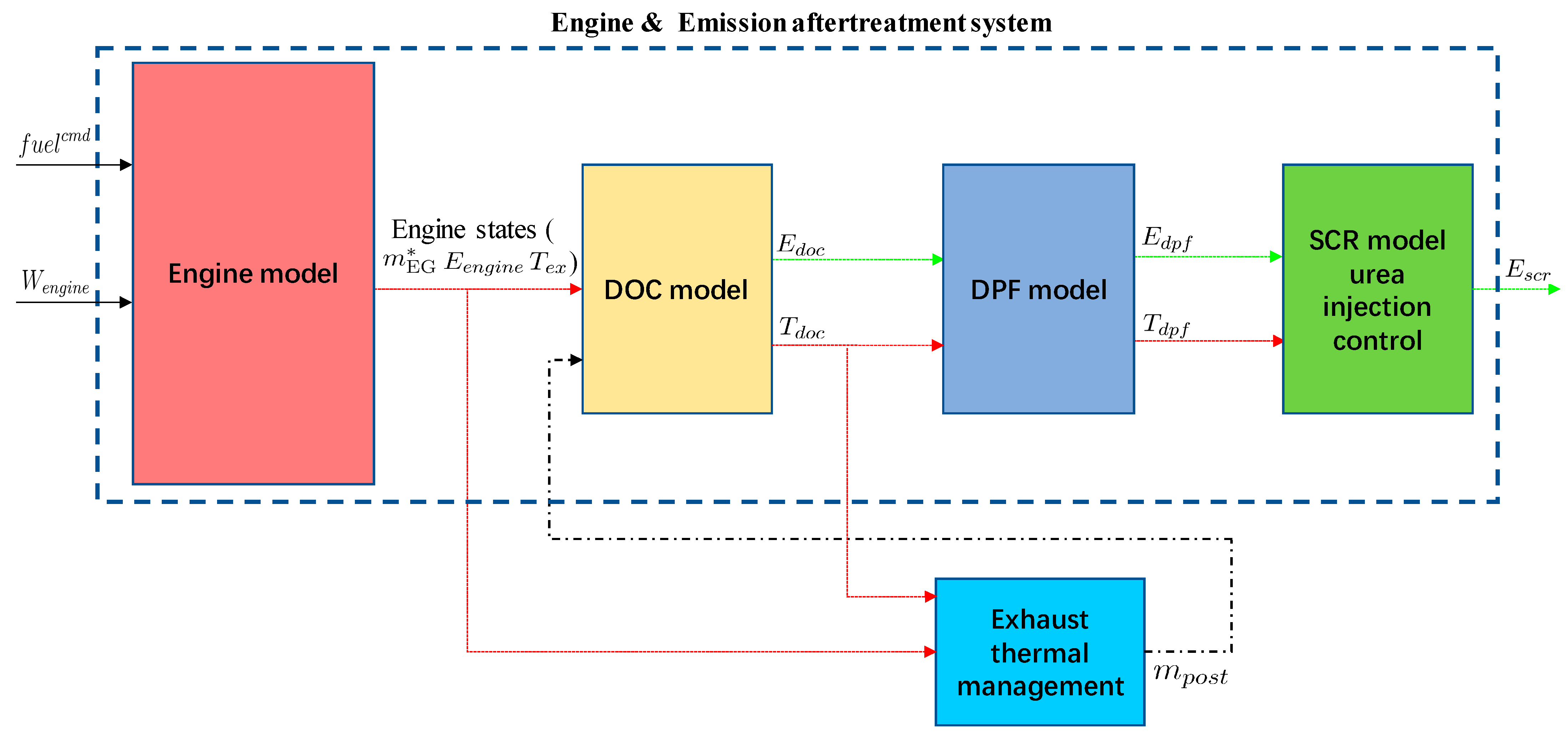
2. DHEV Model
2.1. Planetary Gear Set and Vehicle Model
2.2. Exhaust Thermal Management Model
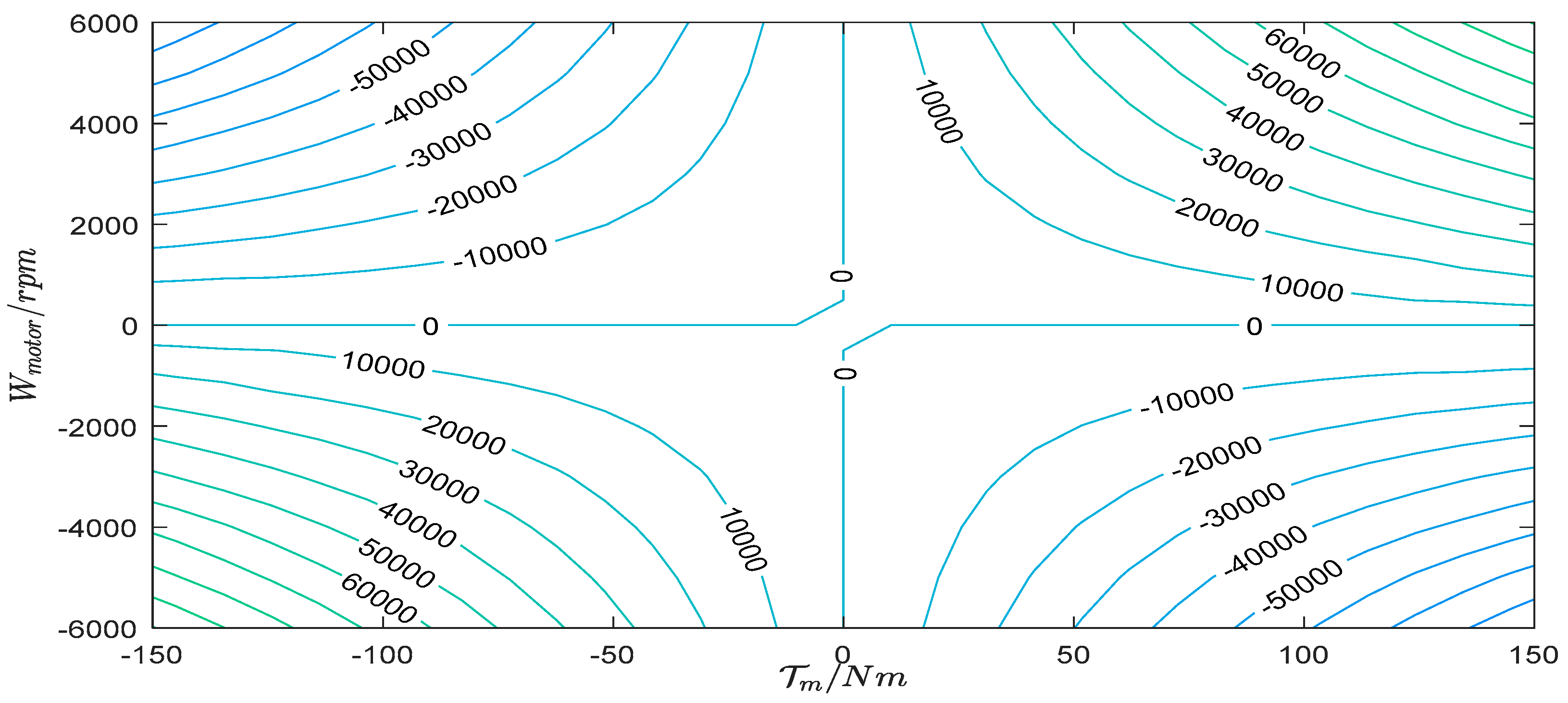
2.3. Electric Motor and Generator Model
2.4. Battery Model
2.5. Hybrid Controller Model
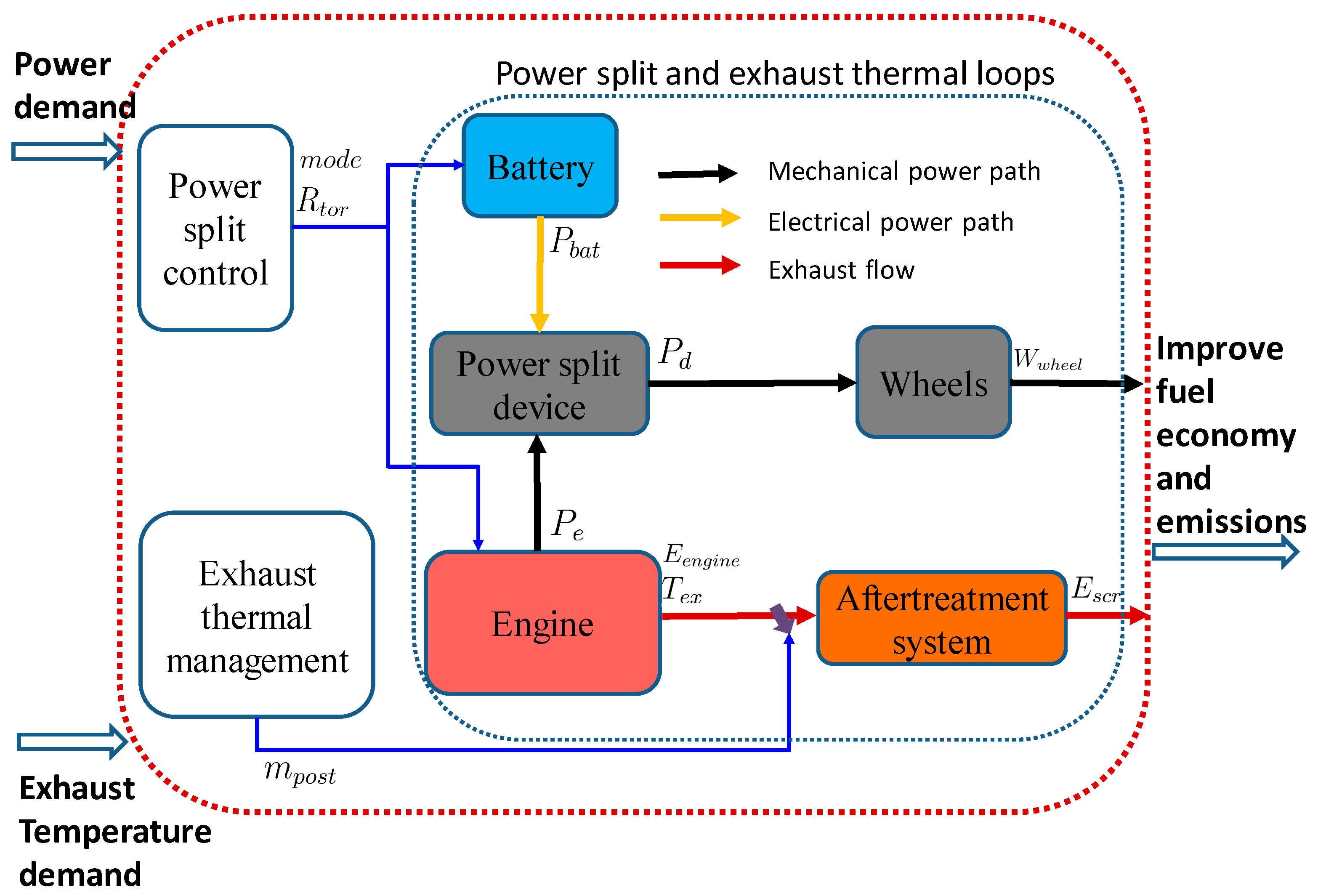
2.6. General Problem Statement of the Power Split and Exhaust Thermal Management
3. Two Power Split Method and Their Evaluation
3.1. The Rule-Based Power Split Method and Its Evaluation
- When (the battery energy is sufficient), and , the working mode of the power split is the motor mode, and .
- When , the working mode of the power split is the engine mode, and .
- When and , the working mode of the power split is the hybrid mode, and and .
3.2. The Optimization-Based Power Split Method and Its Evaluation
4. The Power Split Combining the Rule-Based and the Optimization-Based Methods and Their Comparison on Control Effectiveness
4.1. Fuel Optimized Controller, FOC
4.2. Fuel and Thermal Optimized Controller, FTOC
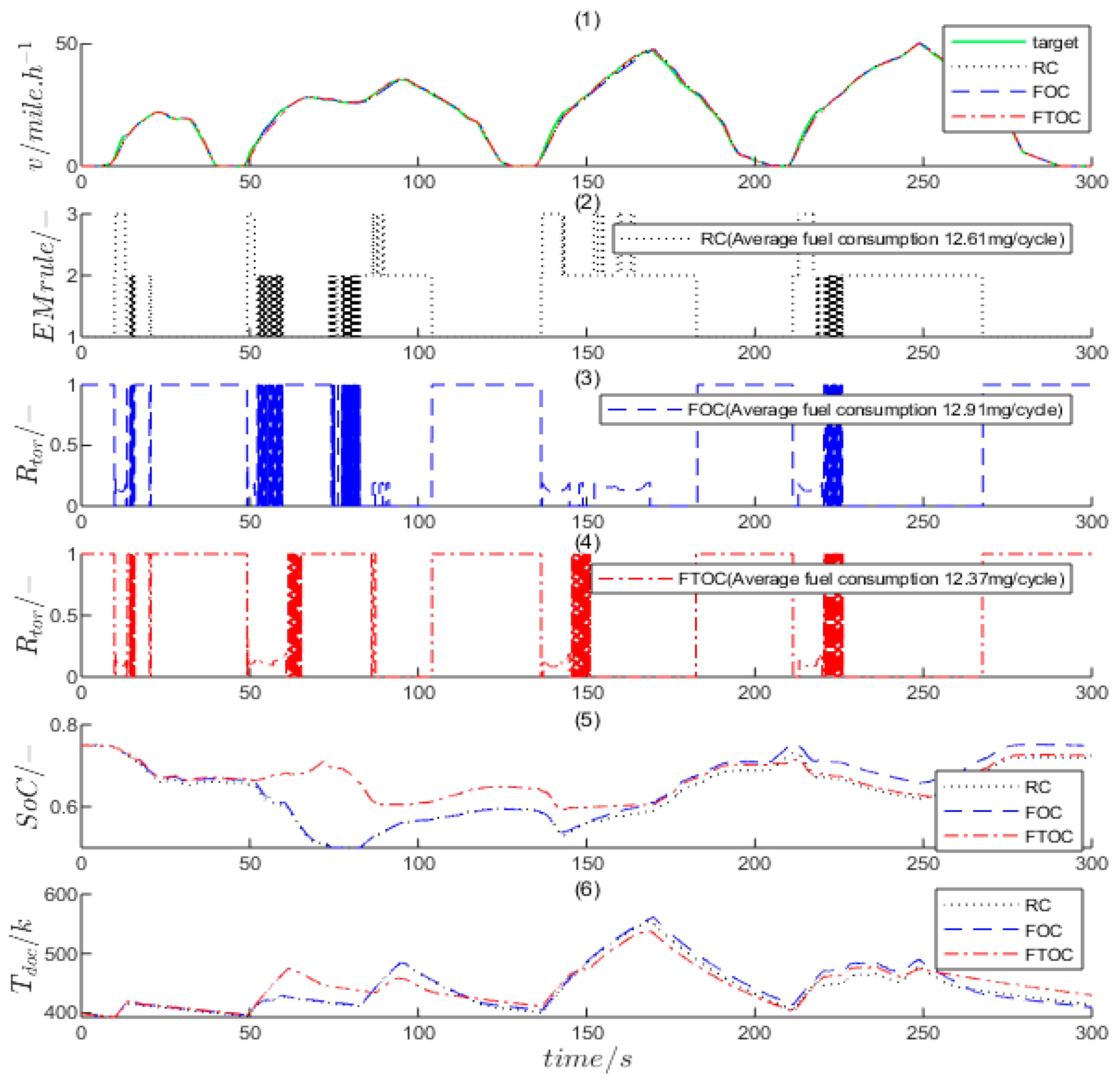
4.3. Evaluation of the Controllers for Power Split
5. Design and Evaluation of Two Optimization-Based Methods for Coordinating the Power Split and the Exhaust Thermal Management
5.1. Overall Design Structure of the Two Controllers
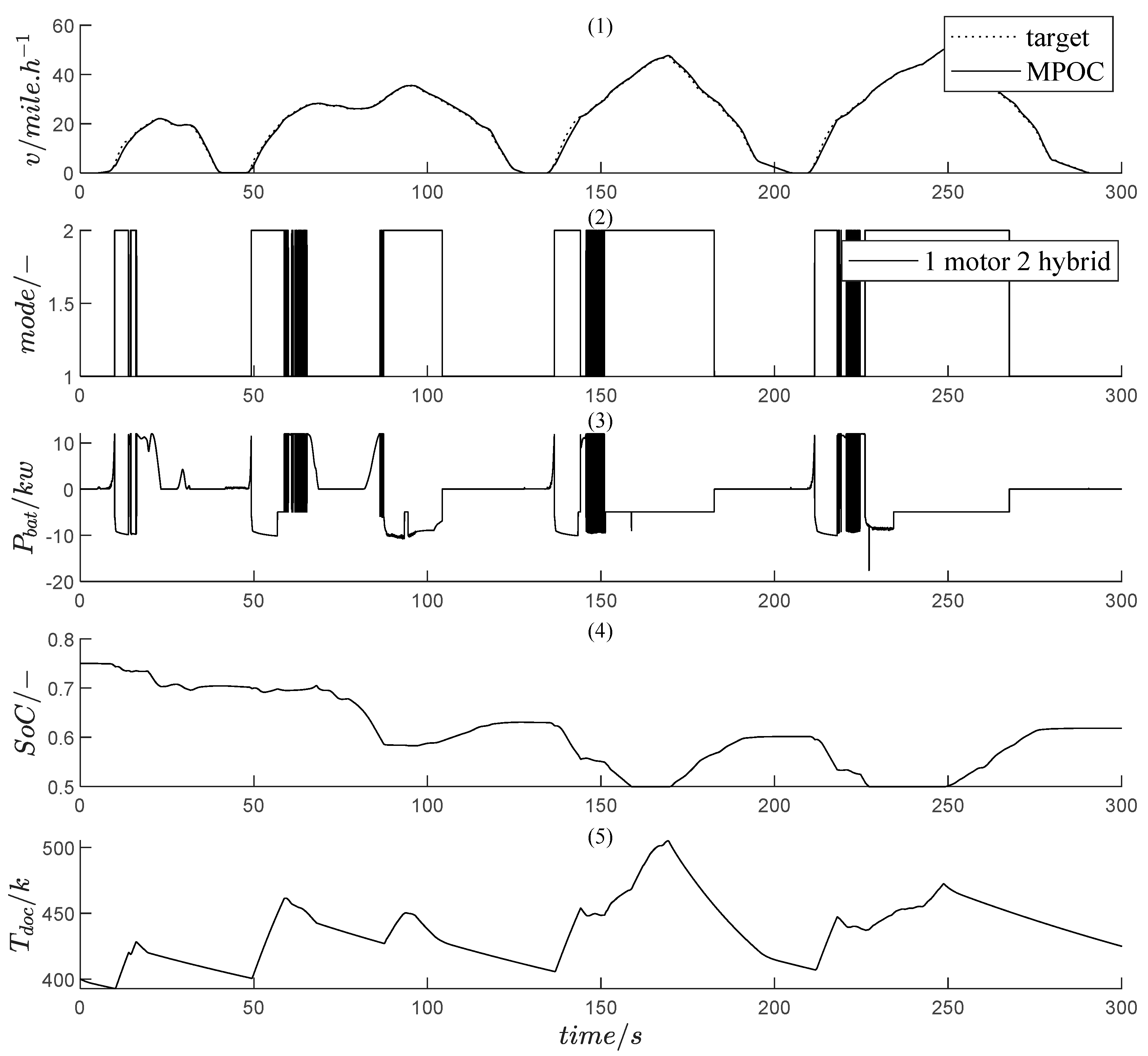
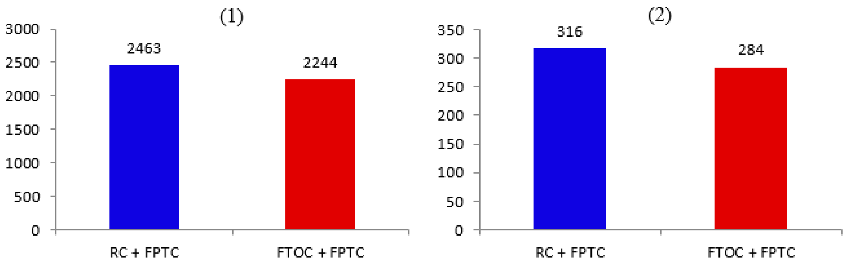
5.2. Evaluation of the Two Controllers
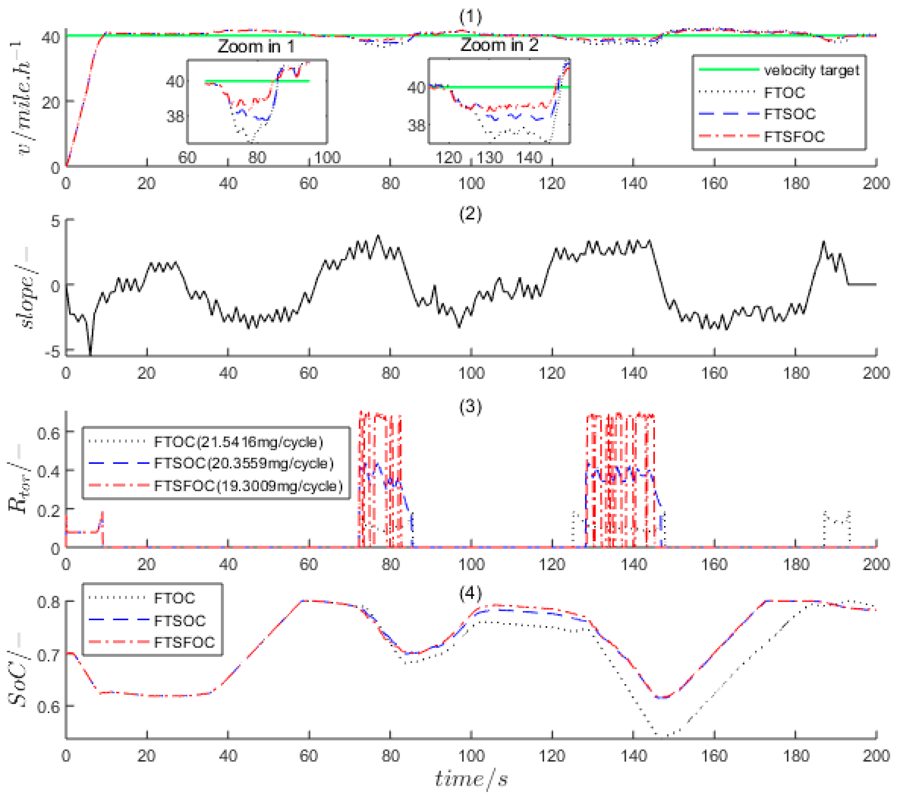
6. Evaluation for the Information of Road Grade on the DHEV
7. Conclusions
Author Contributions
Funding
Conflicts of Interest
References
- Zhao, J.H.; Hu, Y.F.; Gong, X.; Chen, H. Modelling and control of urea-SCR systems through the triple-step nonlinear method in consideration of time-varying parameters and reference dynamics. Trans. Inst. Meas. Control 2018, 40, 287–602. [Google Scholar] [CrossRef]
- Weiss, M.; Bonnel, P.; Hummel, R.; Steininger, N. A Complementary Emissions Test for Light-Duty Vehicles: Assessing the Technical Feasibility of Candidate Procedures; European Commission, Joint Research Centre: Ispra, Italy, 2013. [Google Scholar]
- Weiss, M.; Bonnel, P.; Hummel, R.; Provenza, A.; Manfredi, U. On-road emissions of light-duty vehicles in Europe. Environ. Sci. Technol. 2011, 45, 8575–8581. [Google Scholar] [CrossRef]
- Onori, S.; Tribioli, L. Adaptive Pontryagin’s Minimum Principle supervisory controller design for the plug-in hybrid GM Chevrolet Volt. Appl. Energy 2015, 147, 224–234. [Google Scholar] [CrossRef]
- Reitz1, H.R.; Ogawa, H.; Payri, R. The future of the internal combustion engine. Int. J. Engine Res. 2019, 1–8. [Google Scholar] [CrossRef] [Green Version]
- Tobias, N.; Alberto, C.; Giorgio, M.; Nicolò, C. Equivalent Consumption Minimization Strategy for the Control of Real Driving NOx Emissions of a Diesel Hybrid Electric Vehicle. Energies 2014, 7, 3148–3178. [Google Scholar]
- Tribioli, L.; Barbieri, M.; Capata, R.; Sciubba, E.; Jannelli, E.; Bella, G. A Real Time Energy Management Strategy for Plug-in Hybrid Electric Vehicles based on Optimal Control Theory. Energy Procedia 2014, 45, 949–958. [Google Scholar] [CrossRef]
- Schouten, N.J.; Salman, M.A.; Kheir, N.A. Fuzzy logic control for parallel hybrid vehicles. IEEE Trans. Control Syst. Technol. 2002, 10, 460–468. [Google Scholar] [CrossRef]
- Serrao, L.; Onori, S.; Sciarretta, A.; Guezennec, Y.; Rizzoni, G. Optimal energy management of hybrid electric vehicles including battery aging. In Proceedings of the 2011 American Control Conference, San Francisco, CA, USA, 29 June–1 July 2011; pp. 2125–2130. [Google Scholar] [CrossRef]
- Prokhorov, D.V. Toyota prius HEV neuro control and diagnostics. Neural Netw. 2008, 21, 458–465. [Google Scholar] [CrossRef]
- Lin, C.C.; Peng, H.; Grizzle, J.W.; Kang, J.M. Power management strategy for a parallel hybrid electric truck. IEEE Trans. Control Syst. Technol. 2003, 11, 839–849. [Google Scholar]
- Paganelli, G.; Ercole, G.; Brahma, A.; Guezennec, Y.; Rizzoni, G. General supervisory control policy for the energy optimization of charge sustaining hybrid electric vehicles. JSAE Rev. 2001, 22, 511–518. [Google Scholar] [CrossRef]
- Paganelli, G.; Tateno, M.; Brahma, A.; Rizzoni, G.; Guezennec, Y. Control development for a hybrid-electric sport-utility vehicle: Strategy, implementation and field test results. In Proceedings of the 2001 American Control Conference, Arlington, VA, USA, 25–27 June 2001; Volume 6, pp. 5064–5069. [Google Scholar]
- Zhao, D.; Stobart, R.; Dong, G.; Winward, E. Real-Time Energy Management for Diesel Heavy Duty Hybrid Electric Vehicles. IEEE Trans. Control Syst. Technol. 2015, 23, 829–841. [Google Scholar] [CrossRef] [Green Version]
- Borhan, H.; Vahidi, A.; Phillips, A.M.; Kuang, M.L.; Kolmanovsky, I.V.; Cairano, S.D. MPC-based energy management of a power-split hybrid electric vehicle. IEEE Trans. Control Syst. Technol. 2012, 20, 593–603. [Google Scholar] [CrossRef]
- Gill, P.E.; Murray, W.; Saunders, M.A. SNOPT: An SQP algorithm for largescale constrained optimization. SIAM Rev. 2005, 47, 99–131. [Google Scholar] [CrossRef]
- Nüesch, T.; Wang, M.; Isenegger, P.; Ondera, C.H.; Steinerb, R.; Macri-Lassusb, P.; Guzzellaa, L. Optimal energy management for a diesel hybrid electric vehicle considering transient PM and quasi-static NOx emissions. Control Eng. Pract. 2014, 29, 266–276. [Google Scholar] [CrossRef]
- Grondin, O.; Thibault, L.; Moulin, P.; Chasse, A.; Sciarretta, A. Energy Management Strategy for Diesel Hybrid Electric Vehicle. In Proceedings of the 2011 IEEE Vehicle Power and Propulsion Conference (VPPC), Chicago, IL, USA, 6–9 September 2011; pp. 1–8. [Google Scholar]
- Wang, Y.; Zhang, H.; Sun, Z. Optimal control of the transient emissions and the fuel efficiency of a diesel hybrid electric vehicle. Proc. Inst. Mech. Eng. Part D J. Automob. Eng. 2013, 227, 1546–1561. [Google Scholar] [CrossRef]
- Grondin, O.; Thibault, L.; Quérel, C. Transient torque control of a diesel hybrid powertrain for NOx limitation. 2012 IFAC Workshop on Engine and Powertrain Control. Simul. Model. 2012, 3, 286–295. [Google Scholar]
- Huo, Y.; Yan, F.; Feng, D. A hybrid electric vehicle energy optimization strategy by using fueling control in diesel engines. Proc. Inst. Mech. Eng. Part D J. Automob. Eng. 2019, 233, 517–530. [Google Scholar] [CrossRef]
- Planakis, N.; Karystinos, V.; Papalambrou, G.; Kyrtatos, N. Nonlinear Model Predictive Control for the Transient Load Share Management of a Hybrid Diesel-Electric Marine Propulsion Plant. In Proceedings of the 2020 American Control Conference (ACC), Denver, CO, USA, 1–3 July 2020; pp. 1955–1960. [Google Scholar]
- Rasoul, S.; Stefanopoulou, A.; Mahesh, S.; Allain, M. Reduced-Order Long-Horizon Predictive Thermal Management for Diesel Engine Aftertreatment Systems. In Proceedings of the 2019 American Control Conference (ACC), Philadelphia, PA, USA, 10–12 July 2019; pp. 1611–1616. [Google Scholar]
- Zhao, J.; Wang, J. Integrated Model Predictive Control of Hybrid Electric Vehicle Coupled with Aftertreatment Systems. IEEE Trans. Veh. Technol. 2016, 65, 1199–1211. [Google Scholar] [CrossRef]
- Kessels, J.; Willems, F.; Schoot, W.; Bosch, P. Integrated Energy & Emission Management for Hybrid Electric Truck with SCR Aftertreatment. In Proceedings of the IEEE Vehicle Power and Propulsion Conference, VPPC 2010, Lille, Belgium, 1–3 September 2010; pp. 1–6. [Google Scholar]
- Chen, P.; Wang, J. Coordinated Active Thermal Management and Selective Catalytic Reduction Control for Simultaneous Fuel Economy Improvement and Emissions Reduction During Low-Temperature Operations. J. Dyn. Syst. Meas. Control 2015, 137, 634–641. [Google Scholar] [CrossRef]
- Feru, E.; Murgovski, N.; Jager, B.D.; Willems, F. Supervisory control of a heavy-duty diesel engine with an electrified waste heat recovery system. Control Eng. Pract. 2016, 54, 190–201. [Google Scholar] [CrossRef]
- Gallus, J.; Kirchner, U.; Vogt, R.; Benter, T. Impact of driving style and road grade on gaseous exhaust emissions of passenger vehicles measured by a portable emission measurement system (PEMS). Transp. Res. D Transp. Environ. 2017, 52, 215–226. [Google Scholar] [CrossRef]
- Wyatt, D.W.; Hu, L.; Tate, J.E. Modelling the effect of road grade on the CO2 and NOx emissions of a passenger car through a real world-urban traffic network. In Proceedings of the 20th International Transport and Air Pollution Conference, Graz, Austria, 18–19 September 2014; Available online: http://eprints.whiterose.ac.uk/93926/ (accessed on 20 April 2017).
- Chen, H.; Guo, L.L.; Gong, X.; Gao, B.Z. Automotive Control in Intelligent Era. Acta Autom. Sin. 2020, 46, 1313–1332. [Google Scholar]
- Zeng, X.; Wang, J. A parallel hybrid electric vehicle energy management strategy using stochastic model predictive control with road grade preview. IEEE Trans. Control Syst. Technol. 2015, 23, 2416–2423. [Google Scholar] [CrossRef]
- Lu, J.; Hong, S.; Sullivan, J.; Hu, G.; Dai, E.; Reed, D.; Baker, R. Predictive transmission shift schedule for improving fuel economy and drivability using electronic horizon. SAE Int. J. Engines 2017, 10, 680–688. [Google Scholar] [CrossRef]
- Ozatay, E.; Ozguner, U.; Michelini, J.; Filev, D. Analytical solution to the minimum energy consumption based velocity profile optimization problem with variable road grade. IFAC Proc. Vol. 2014, 47, 7541–7546. [Google Scholar] [CrossRef] [Green Version]
- Ma, Y.; Wang, J. Integrated Power Management and Aftertreatment System Control for Hybrid Electric Vehicles With Road Grade Preview. IEEE Trans. Veh. Technol. 2017, 66, 10935–10945. [Google Scholar] [CrossRef]
- Guo, L.L.; Gao, B.Z.; Gao, Y.; Chen, H. Optimal Energy Management for HEVs in Eco-Driving Applications Using Bi-Level MPC. IEEE Trans. Intell. Transp. Syst. 2017, 18, 2153–2162. [Google Scholar] [CrossRef]
- Zeng, X.H.; Yang, N.N.; Dafeng, S.; Chang, Z. Multi-factor integrated parametric design of power-split hybrid electric bus. J. Clean. Prod. 2016, 115, 88–100. [Google Scholar] [CrossRef]
- Zeng, X.H.; Yang, N.N.; Wang, J.N.; Dafeng, S.; Nong, Z. Predictive-model-based dynamic coordination control strategy for power-split hybrid electric bus. Mech. Syst. Signal Process. 2015, 60–61, 785–798. [Google Scholar] [CrossRef]
- Eriksson, L.; Lindell, T.; Leufvén, O.; Thomasson, A. Scalable component-based modeling for optimizing engines with supercharging, e-boost and turbocompound concepts. SAE Int. J. Engines 2012, 5, 579–595. [Google Scholar] [CrossRef]
- Eriksson, L.; Thomasson, A.; Ekberg, K.; Reig, A.; Eifert, M.; Donatantonio, F.; D’Amato, A.; Arsie, I.; Pianese, C.; Otta, P. Look-ahead controls of heavy duty trucks on open roads six benchmark solutions. Control Eng. Pract. 2019, 83, 45–66. [Google Scholar] [CrossRef]
- Zhao, J.H.; Zhou, S.; Hu, Y.; Ju, M.; Ren, R.; Chen, H. Open-source dataset for control oriented modelling in diesel engines. Sci. China Inf. Sci. 2019, 62, 077201. [Google Scholar] [CrossRef] [Green Version]
- Gong, X.; Wang, H.; Amini, M.R.; Kolmanovsky, I.; Sun, J. Integrated optimization of power split, engine thermal management, and cabin heating for hybrid electric vehicles. In Proceedings of the IEEE Conference on Control Technology and Applications (CCTA), Hong Kong, China, 19–21 August 2019; pp. 567–572. [Google Scholar]
- Tucki, K. A Computer Tool for Modelling CO2 Emissions in Driving Tests for Vehicles with Diesel Engines. Energies 2021, 14, 266. [Google Scholar] [CrossRef]


| Symbol | Description | Value (Unit) |
|---|---|---|
| Vehicle mass | 2500 (kg) | |
| Face area | 2.52 (m2) | |
| Dynamic tire radius | 0.51 (m) | |
| Specific heat at constant pressure of the exhaust gas | 1 × 10³ (J/kgK) | |
| Specific heat of the catalysts | 996 (J/kgK) | |
| Mass of the catalytic converter of DOC | 19 (kg) | |
| Mass of the catalytic converter of DPF | 9.3 (kg) | |
| Mass of the catalytic converter of SCR | 5.2 (kg) | |
| Radiation coefficient of silencer of DOC | 0.61 (-) | |
| Radiation coefficient of silencer of DPF | 0.49 (-) | |
| Radiation coefficient of silencer of SCR | 0.557 (-) | |
| Radiation constant | 5.07 × 10⁸ (-) | |
| Radiating surface area of the silencer of DOC | 0.226 (m2) | |
| Radiating surface area of the silencer of DPF | 0.452 (m2) | |
| Radiating surface area of the silencer of SCR | 1 (m2) |
| Symbol | ||||||
|---|---|---|---|---|---|---|
| Value | 0.006556 | 0.2486 | 1.004 | 1.985 × 10⁸ | 2.481 × 10⁷ | −2030 |
Publisher’s Note: MDPI stays neutral with regard to jurisdictional claims in published maps and institutional affiliations. |
© 2021 by the authors. Licensee MDPI, Basel, Switzerland. This article is an open access article distributed under the terms and conditions of the Creative Commons Attribution (CC BY) license (https://creativecommons.org/licenses/by/4.0/).
Share and Cite
Zhao, J.; Hu, Y.; Xie, F.; Li, X.; Sun, Y.; Sun, H.; Gong, X. Modeling and Integrated Optimization of Power Split and Exhaust Thermal Management on Diesel Hybrid Electric Vehicles. Energies 2021, 14, 7505. https://doi.org/10.3390/en14227505
Zhao J, Hu Y, Xie F, Li X, Sun Y, Sun H, Gong X. Modeling and Integrated Optimization of Power Split and Exhaust Thermal Management on Diesel Hybrid Electric Vehicles. Energies. 2021; 14(22):7505. https://doi.org/10.3390/en14227505
Chicago/Turabian StyleZhao, Jinghua, Yunfeng Hu, Fangxi Xie, Xiaoping Li, Yao Sun, Hongyu Sun, and Xun Gong. 2021. "Modeling and Integrated Optimization of Power Split and Exhaust Thermal Management on Diesel Hybrid Electric Vehicles" Energies 14, no. 22: 7505. https://doi.org/10.3390/en14227505