
Influence of Upstream Disturbances on the Vortex Structure of Francis Turbine Based on the Criteria of Identification of Various Vortexes


1
Department of Engineering Mechanics, Faculty of Civil Engineering and Mechanics, Kunming University of Science and Technology, Kunming 650500, China
2
State Key Laboratory of Hydropower and Mountain River Engineering, Sichuan University, Chengdu 610065, China
*
Authors to whom correspondence should be addressed.
Energies 2021, 14(22), 7626; https://doi.org/10.3390/en14227626
Submission received: 14 October 2021
/
Revised: 5 November 2021
/
Accepted: 13 November 2021
/
Published: 15 November 2021
(This article belongs to the Special Issue Advances in Pumped Storage Hydraulic System)
Abstract
:The inter-blade passage vortex, the vortex rope of the draft tube, and the vortex in the guide apparatus are the characteristics of flow instability of the Francis turbine, which may lead to fatigue failure in serious cases. In the current study, in order to accurately capture the transient turbulent characteristics of flow under different conditions and fully understand the flow field and vortex structure, we conduct a simulation that adopts sliding grid technology and the large-eddy simulation (LES) method based on the wall-adapting local eddy viscosity (WALE) model. Using the pressure iso-surface method, the Q criterion, and the latest third-generation Liutex vortex identification method, this study analyzes and compares the inter-blade passage vortex, the vortex rope of the draft tube, and the outflow and vortex in the guide apparatus, focusing on the capture ability of flow field information by various vortex identification methods and the unique vortex structure under the condition of a small opening. The results indicate that the dependence of Liutex on the threshold is small, and the scale range of the flow direction vortex captured by Liutex is wider, but the ability of the spanwise vortex is relatively weak. The smaller the opening, the more disorderly the vortexes generated in each component and the more unstable the flow field. In the draft tube, the original shape of the vortex rope is destroyed due to the interaction between vortexes. Under the condition of a small opening, an inter-blade passage vortex is generated, affecting the efficient and stable operation of the turbine.
1. Introduction
Hydropower is the largest source of renewable energy at present, with the greatest potential for large-scale development. By the end of 2020, China’s installed capacity of hydropower reached 370 GW, accounting for 39.6% of renewable energy. The turbine is the core component of hydropower generation unit, among which the Francis turbine accounts for more than 60% of the total installed capacity and is the most widely used type at present [1]. Currently, there are a large number of vortex structures with different scales and intensities in Francis turbines. The spatiotemporal evolution of these vortex structures (draft tube vortex rope, inter-blade passage vortex, etc.) in the passage and its induced vibration are the main causes of damage to turbine components, which leads to the Francis turbine often suffering from severe low-frequency and high-amplitude hydraulic instability, thereby considerably affecting its safe and stable operation [2,3,4]. Due to the complexity, diversity, and randomness of turbulence, fluid-induced vibration has become the main cause of abnormal vibration in hydraulic machinery. Therefore, accurate identification of vortex structures plays a critical role in reducing the damage of turbine components and understanding the internal flow mechanism of the turbine [5].
Guo [6,7] used sliding grid technology and the large-eddy simulation (LES) method based on the Vreman subgrid-scale model to obtain the distribution of velocity, pressure, and vorticity in the whole passage of the Francis turbine and to capture the unique flow pattern around the guide vane and the spatiotemporal evolution of the inter-blade passage vortex. Wang et al. [8,9,10] numerically simulated the turbulent flow in the three-dimensional blade passage of the Francis turbine by using the LES method to examine the distribution of strongly distorted wake in the blade passage. It has been concluded that the existence of strong wake leads to the separation of fluid at the leading edge of the blade passage, which evolves and splits into smaller vortex trains at the downstream, thus resulting in the instability of flow in the blade passage. The rotating vortex rope (RVR) caused by flow instabilities in the draft tube affects the hydraulic turbine’s efficiency and wear. The exact procedure of RVR formation remains vague. Therefore, it is important to accurately capture and analyze the formation of the vortex rope in the draft tube by adopting the appropriate vortex identification methods. [11,12,13,14,15] Attempting to remedy the problems of vorticity-based methods, such methods have been introduced and widely used in vortex structure visualization over the last 30 years. Although second-generation criteria, such as Δ [16], Q [17], λ2 [18], and λci [19] criteria, have been able to judge the presence of the local rotational motion to some extent, these methods need to adjust the threshold to accurately visualize the iso-surface plot. Dong and Liu [20,21,22,23,24] proposed a more precise definition of the vortex and vortex vector based on the DNS method called Liutex. The method combines vorticity conservation law and the vorticity transport equation to analyze the correlation between vorticity and rotation and mode decomposition and to describe the vortex structure in the flow field on the basis of the Liutex line, the Liutex iso-surface, and the Liutex vector field. This method can indicate the local rotation intensity of a vortex and the direction of the rotation axis, which suggests that it is better than many previous methods based on scalars. Zhang et al. [25,26] summarized and classified different vortex identification methods in detail. Several typical vortexes (such as draft tube vortexes, Karman vortexes, and inter-blade passage vortexes) in the turbine are discussed and compared by utilizing the Ω criterion vortex identification method. The results have certain guiding significance for the application of vortex identification in hydraulic machinery, but the method does not involve the latest third-generation Liutex vortex identification method. Chen et al. [27] analyzed the influence of upstream disturbance on the draft-tube flow of the Francis turbine under part-load conditions based on different vortex identification methods. The results show that, when the guide vane opening is small (representing the part-load condition), the upstream disturbance propagates downstream, which has a notable influence on the flow pattern of the downstream draft tube. When the opening approaches the optimal opening, the upstream disturbance becomes weak, which has a very limited influence on the downstream flow pattern. Guo et al. [28,29] analyzed the abilities of the Q criterion, Ω criterion, and Liutex to capture the vortex rope in the draft tube. The results suggest that the Q criterion and Liutex have the same ability to capture vortexes and that they can both clearly and reasonably depict the shape of rotating vortexes.
For the Francis turbine, entropy [30,31,32], cavitation [33,34,35,36], pressure fluctuation [37,38], and vortex structure [39] have been the subjects of increasing research interest recently. In this paper, taking the HLA551-LJ-43 Francis turbine as the research object, the vortex structure and flow field distribution in the passage during the guide vane opening transition from the part-load condition to the optimal condition (representing the full-load condition) are analyzed in detail, and the abilities of the Q criterion and Liutex to capture vortexes in the guide apparatus, vortex rope of the draft tube, and inter-blade passage vortex of the Francis turbine are compared.
2. Numerical Set Up
2.1. LES Numerical Model
Cheng [40,41,42] demonstrated that applying large eddy simulation to the Francis turbine has notable advantages over other methods.
The filtered governing equations of Newton’s incompressible viscous flow for the turbine are written as
where is the subgrid stress; and are the filtered velocity in the i direction and the pressure, respectively; represents the fluid density; and represents the kinetic viscosity.
Furthermore, the term in SGS stress is decomposed as
where Lij is Leonard stress, which represents the interaction among large-scale vortexes. Cij is cross-stress, which denotes the interaction between large-scale vortexes and small-scale vortexes. Rij is Reynolds stress, representing the interaction among small-scale vortexes. We need to build a model to simulate these stresses, because the simulation result of the wall-adapting local eddy viscosity model (WALE) is accurate [43]. In this paper, WALE is used to define turbulent eddy viscosity
In the formula, the model parameters are constant, generally at , and the filter size is obtained from the formula . The strain rate tensor is in line with the following equation:
where .
2.2. Vortex Identification Methods
The pressure iso-surface method assumes that the pressure in the center of the vortex core is much lower than that in the surrounding area, so the isobaric surface around the minimum pressure point is used to represent the vortex structure. This method is the simplest and most direct one without mathematical transformation.
The Q criterion is based on the decomposition of the local velocity gradient tensor Dij. Dij = Sij + ωij is carried out to decompose Dij into a symmetric tensor Sij and an antisymmetric tensor ωij, which are, respectively, the deformation and rotation parts of the fluid. The characteristic equation of Dij is as follows:
where P, Q, and R are three invariants of the velocity tensor gradient. Q is defined as
Generally, when Q > 0, the vorticity is dominant and the rotation is greater than the deformation.
Liu et al. proposed a new mathematical definition of the vortex and its vector Liutex, which gives a new mathematical definition of the vortex, namely,. The mathematical expression is as follows:
where
where u and v are velocity components in the x and y directions. Unlike the above Q criterion, which is a scalar method, Liutex is vector method. Its magnitude represents the rigid rotation strength of a fluid, and the rigid rotation axis of fluid particles can be obtained.
According to the definition of Liutex vector R, vorticity ω can be decomposed into rigid rotation R and antisymmetric shear ω-R. Similarly, the velocity gradient tensor v can be decomposed into a rigid rotating part (corresponding to R) and a non-rotating part (N-R). This decomposition is different from the traditional Cauchy–Stokes decomposition, which decomposes v into symmetric and antisymmetric parts and finds the rigid rotating part in the local flow.
2.3. Numerical Simulation Strategy and Boundary Conditions
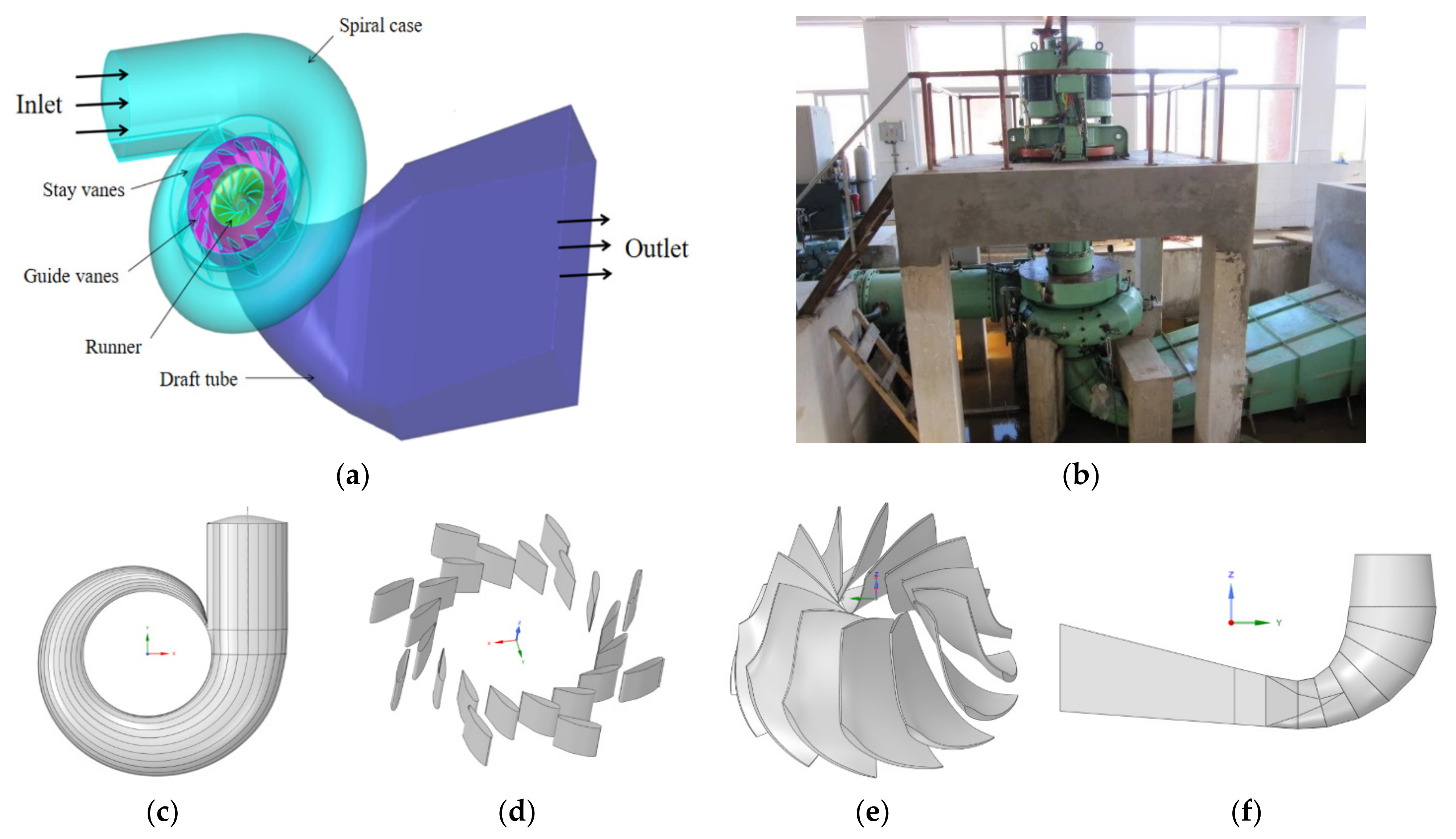
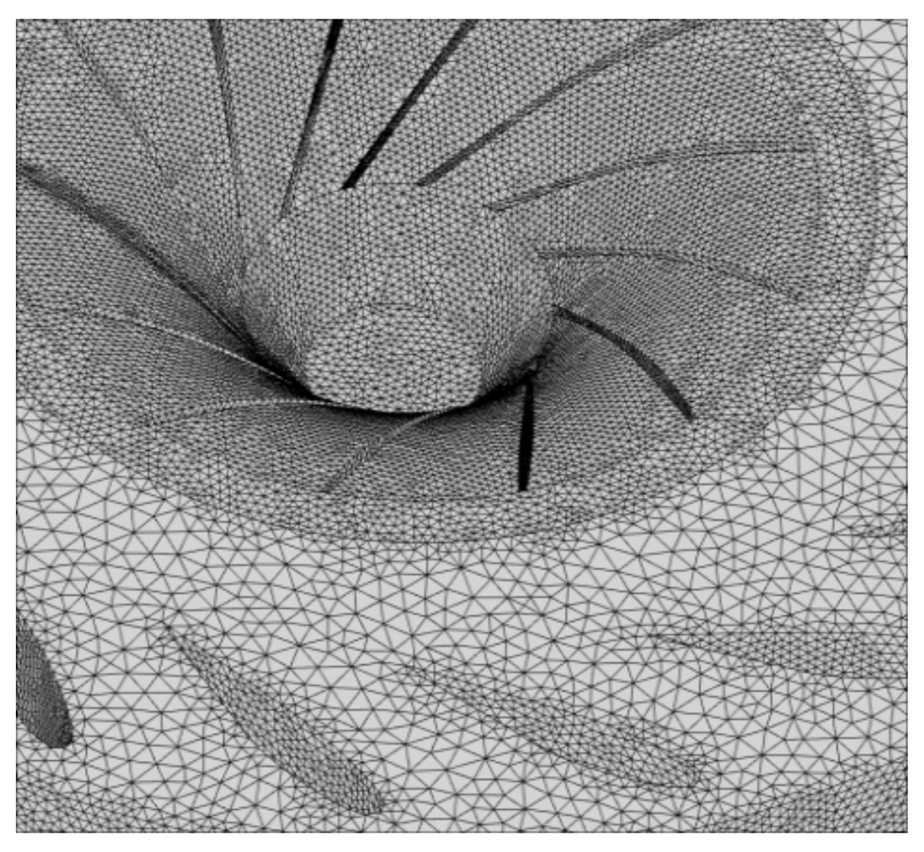
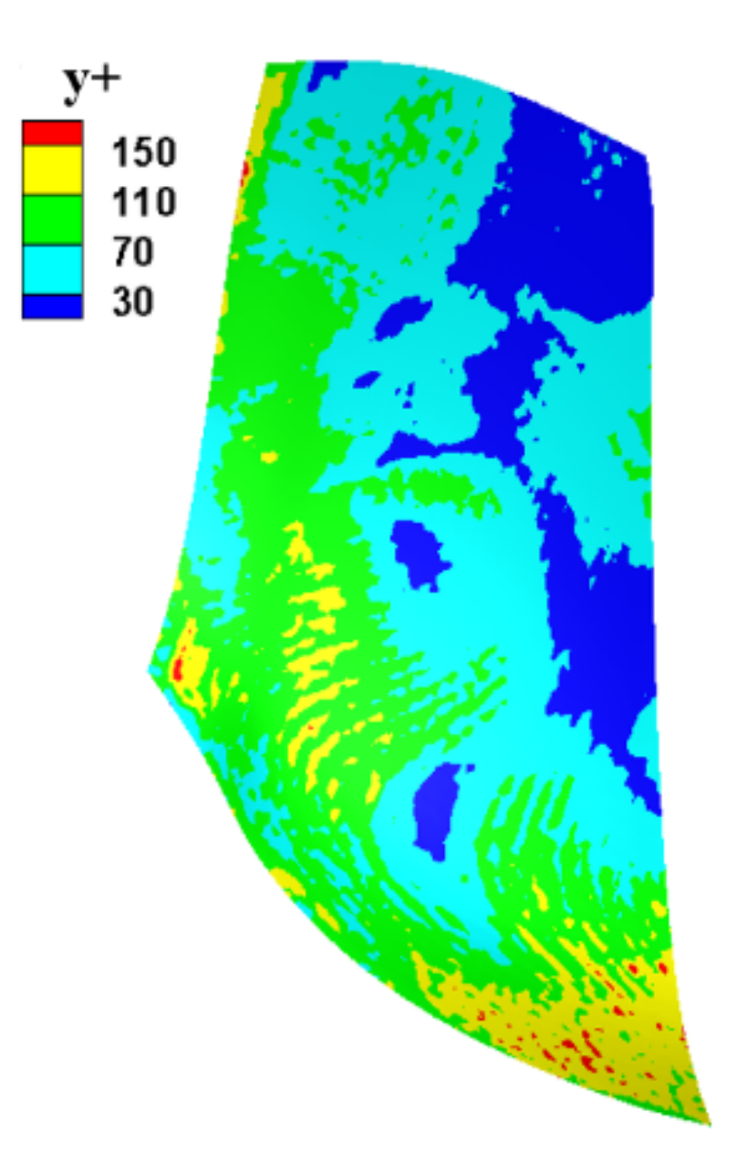
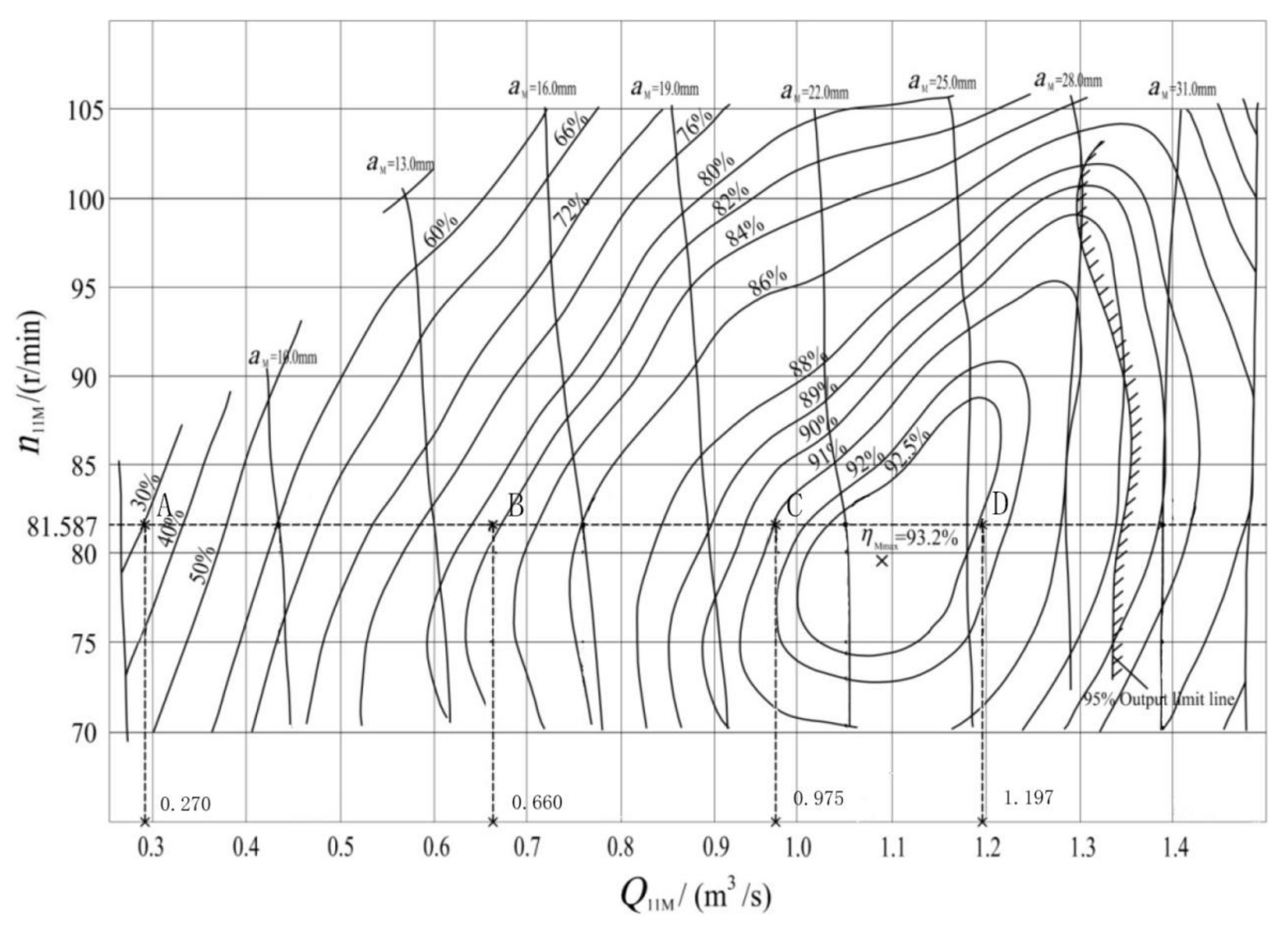
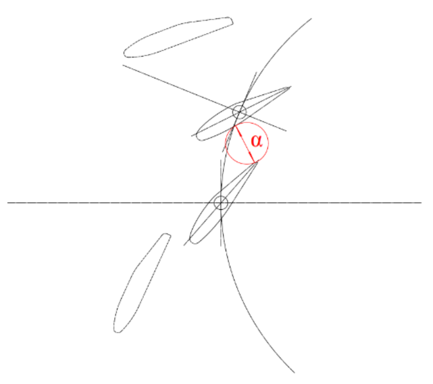
The Francis turbine model is HLA551-LJ-43, and the calculation domain is shown in Figure 1. The model includes a spiral case domain, the guide apparatus (8 stay vanes and 16 guide vanes), a runner domain (13 blades) and a draft tube domain, as shown in Figure 1d,e. Some details of the runner distributor are presented in Table 1. The designed flow rate is 0.7 m3/s, and the designed rotational speed is 600 r/min. Sliding mesh technology is used to set the sliding mesh interface on the dynamic-and-static interface of the runner domain to handle the data transmission of the dynamic-and-static interference flow between the guide vane and runner and the runner and draft tube. Due to the complexity of the geometric model, the mesh is an unstructured tetrahedral mesh. After independence verification, the final number of the mesh is 13.1557 million, of which about half of the total number of mesh, 7.9837 million, accounts for the mesh in the runner area. The mesh generation of the runner and distributor is shown in Figure 2. The average value of y plus nodes on the blade wall is about 60, and their distribution is shown in Figure 3. Due to the limitation of computing resources, the result of this y plus value is reliable [44]. The Dirichlet boundary condition of the velocity inlet is adopted at the spiral case inlet, the outflow boundary condition is adopted at the draft tube outlet, and the wall surface is the non-slip boundary condition. According to Figure 4, the comprehensive characteristic curve and similarity criteria are as follows: α = 13.5 mm (angle of attack 8°), α = 26.17 mm (angle of attack 16°), α = 38.05 mm (angle of attack 24°), and α = 48.74 mm (angle of attack 32°, optimal condition). Four types of guide vane opening conditions are selected, and α represents the shortest distance between the outlet edge of the guide vane and the adjacent guide vane in Figure 5. The power output and efficiency of the four working conditions are shown in Table 2.
The influence of gravity is considered in the calculation. The governing equations are discretized by the finite volume method in space and by the second-order fully implicit scheme in time. The second-order central scheme is used for the diffusion term and pressure term, and the second-order upwind scheme is used for the convection term. The time step is 0.001 s (1/100 of the wheel rotation cycle), and 45 rotation cycles (10 r/s, 4.5 s) are calculated using the commercial software ANSYS FLUENT. For an important calculated physical quantity, such as velocity or pressure, the detection residual error is less than 10−5, the velocity and pressure reach stable values, and the change in inlet and outlet flow is less than 0.1%, which also means that the calculation results converge. The computing results remain stable in the fourth second. Taking the last five rotation cycles for result analysis, the computer time is about two months.
3. Results and Discussion
3.1. Flow Patterns under Various Upstream Disturbances
It can be seen from Figure 6 that under optimal conditions, the flow field in the whole flow passage is smooth and basically no vortex is generated. However, when the unit deviates from the optimal operating conditions (such as a small guide vane opening, representing part-load condition) and the fluid flows through the stay vanes, due to the small opening of the downstream guide vanes, a certain degree of “blocking effect” occurs, which leads to the local fluid having an impact on the stay vanes, resulting in flow separation and the occurrence of a vortex. The interaction of the wake vortexes behind the guide vane is strengthened, resulting in more severe and complex vortexes, flow separation, and other hydraulic instability phenomena, as well as inter-blade passage vortexes. Through comparison, it can be seen that under the optimal condition, the distribution law of the outlet flow angle of the guide vane in the circumferential direction adapts to the shape, the setting angle of the designed stay vane, and the matching of the guide vane. From the optimal condition to the small opening condition, the tangential velocity becomes increasingly dominant, resulting in a lengthened track of the streamline. In addition, the reinforcing intensity of interaction between the fluids results in a more complex flow pattern. Energy loss, vortexes, and upstream disturbance hinder the flow of the downstream fluid field, as shown in Figure 6a.
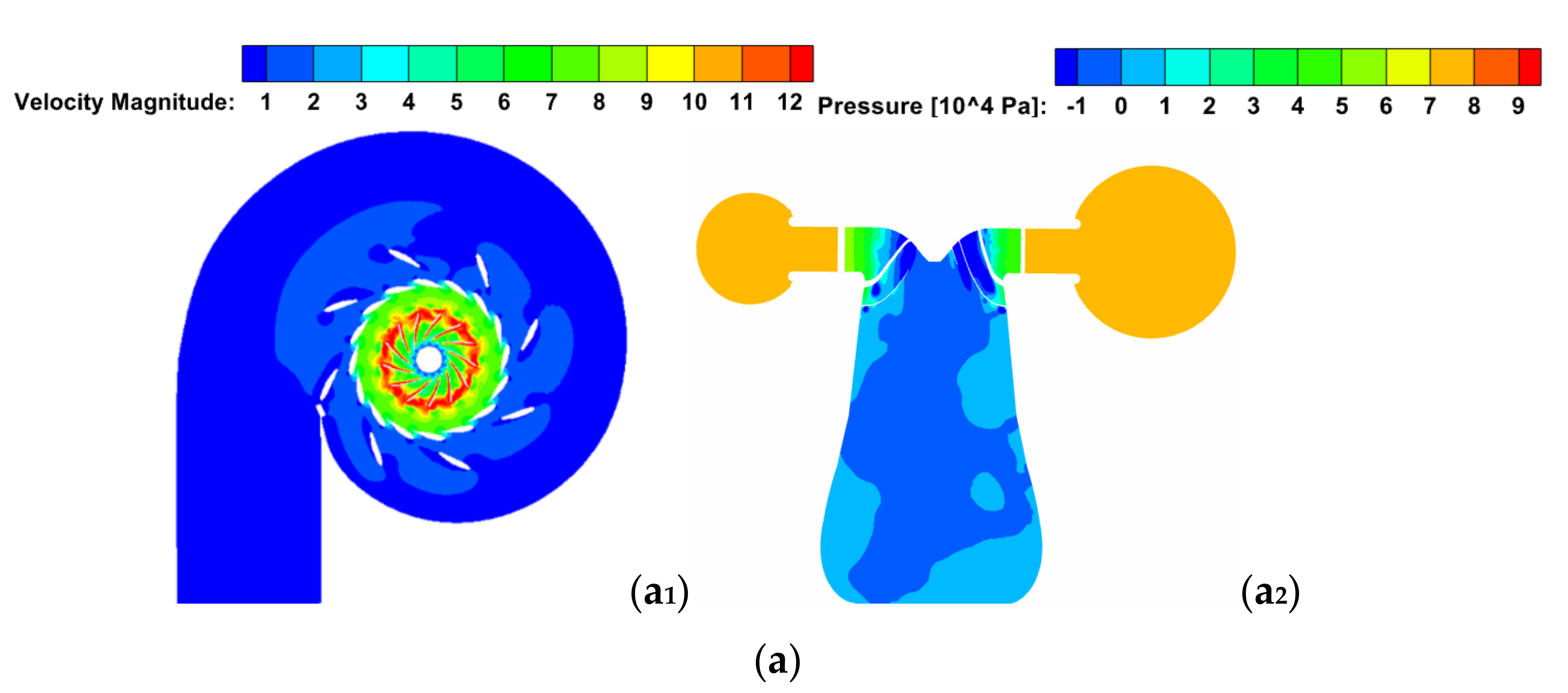
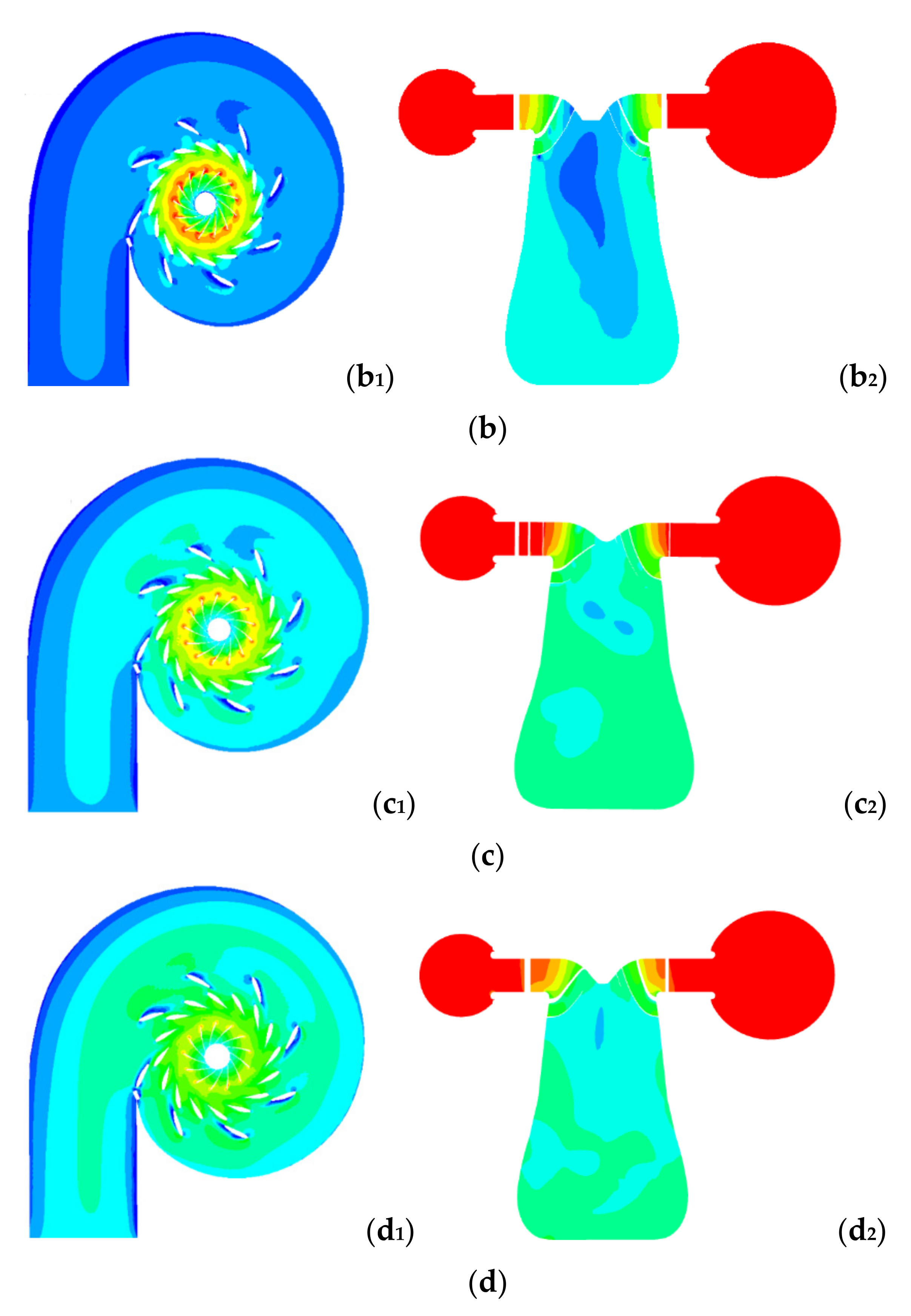
Figure 7 shows the velocity and pressure contour plots in the flow passage of the turbine, from which it can be seen that the velocity and pressure distribution of the spiral case and the vane have good symmetry in the circumferential direction, and the distribution law does not obviously change with the change in the guide vane opening; only the numerical value changes. However, the fluid comes from the spiral case and guide vane domain, whose velocity gradient changes sharply near the runner blade inlet, especially at the slip interface. This shows that the turbulent motion of the fluid is violent after passing through the guide vane, and the fluid is greatly affected by the interference of the runner’s dynamic and static parts. When the fluid flows into the draft tube, there is a large-scale low-pressure zone or even a negative-pressure area in the draft tube. With the decrease in the opening, the range of the low-pressure zone in the middle becomes increasingly larger. With such a small guide vane opening (representing the part-load condition; Figure 7(a2)), the whole draft tube is almost completely filled. This shows that the internal pressure of the draft tube is greatly affected by the opening of the guide vane. The smaller the opening, the more turbulent the flow pattern and the more obvious the phenomenon of low pressure, which is more likely to cause cavitation. The shape and position of the vortex rope in the draft tube also change, which affects the stable operation of the turbine.
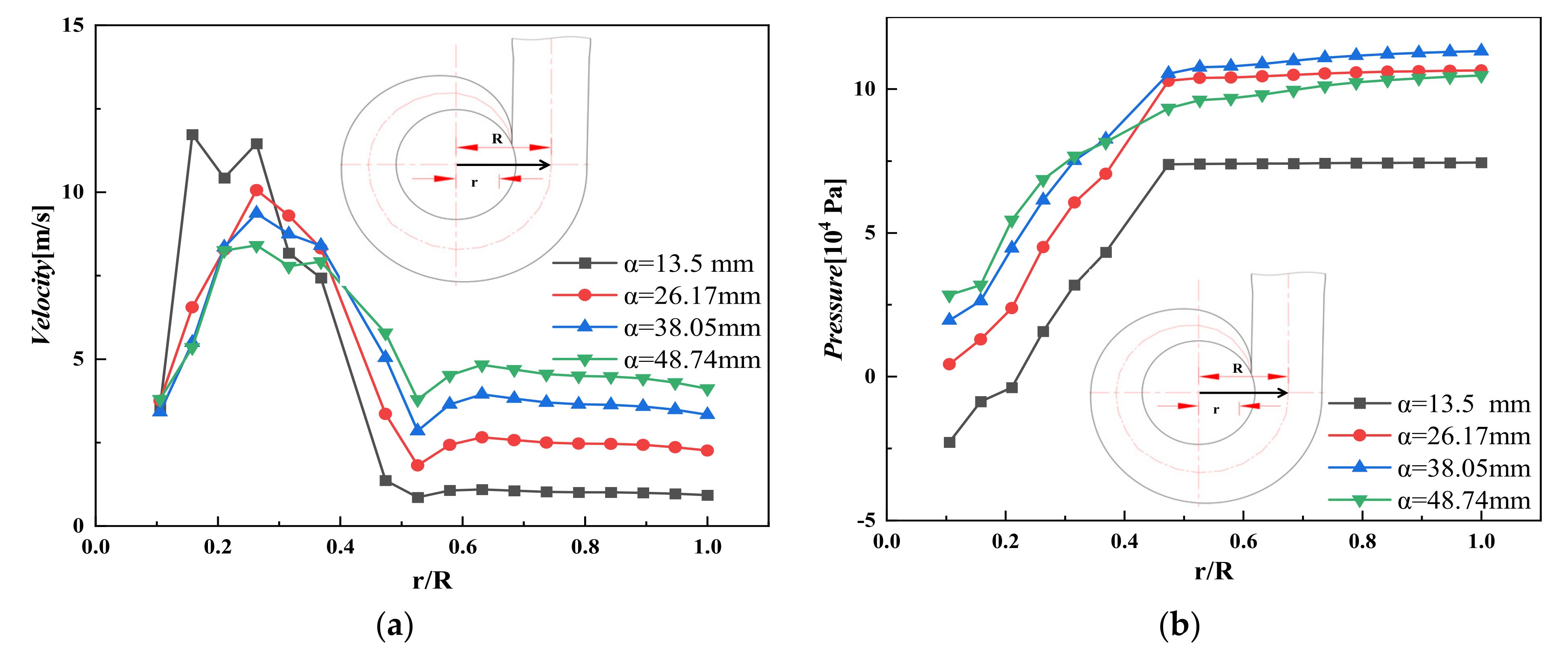
The velocity and pressure paths along the horizontal axis of the meridian section of the spiral case are shown in Figure 8. Axial coordinates refer to the relative distance from the center of the whole Francis turbine in Figure 8. It can also be seen that there is no obvious change in velocity and pressure in the spiral case, but the velocity and pressure gradient of the guide apparatus and runner domain are notably changed, particularly under the small guide vane opening condition. The velocity and pressure at the center of the runner are relatively low, and the velocity is about 3.7 m/s. This shows that the deflection degree of the fluid flow direction varies under different guide vane openings. As the runner rotates, the pressure is gradually released, and the pressure in the guide vane domain decreases sharply, resulting in a larger pressure gradient, which leads to flow separation and the occurrence of a vortex and inter-blade passage vortexes. The instability and rupture of the blade passage vortex amplify the pressure fluctuation and complicate the frequency spectrum.
3.2. Vortex Patterns in the Guide Apparatus and Runner Domain under Different Upstream Disturbances
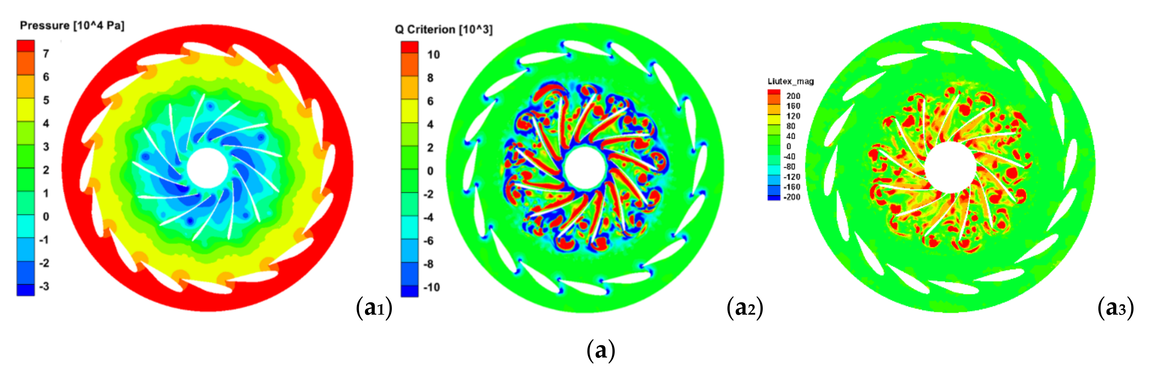
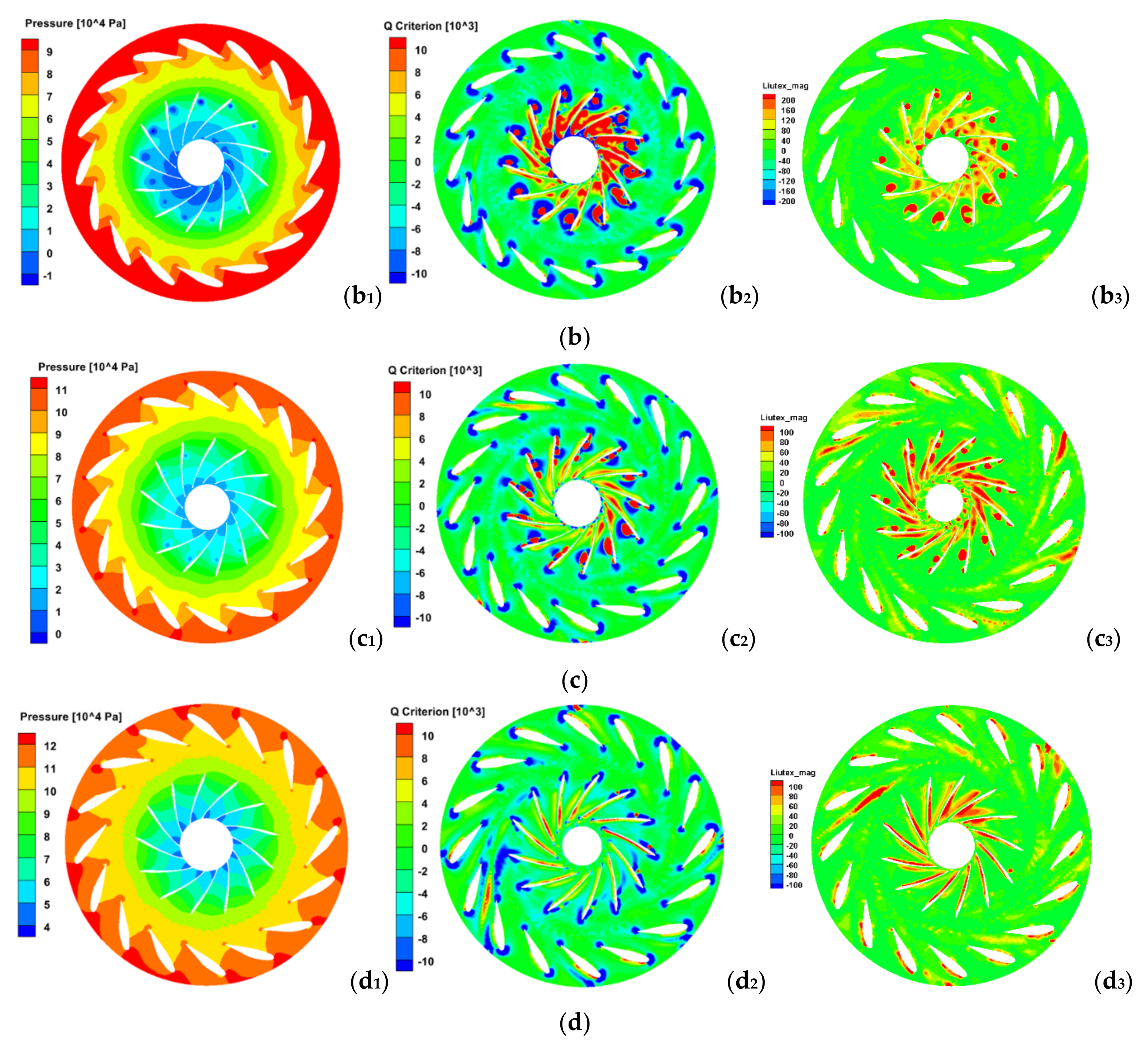
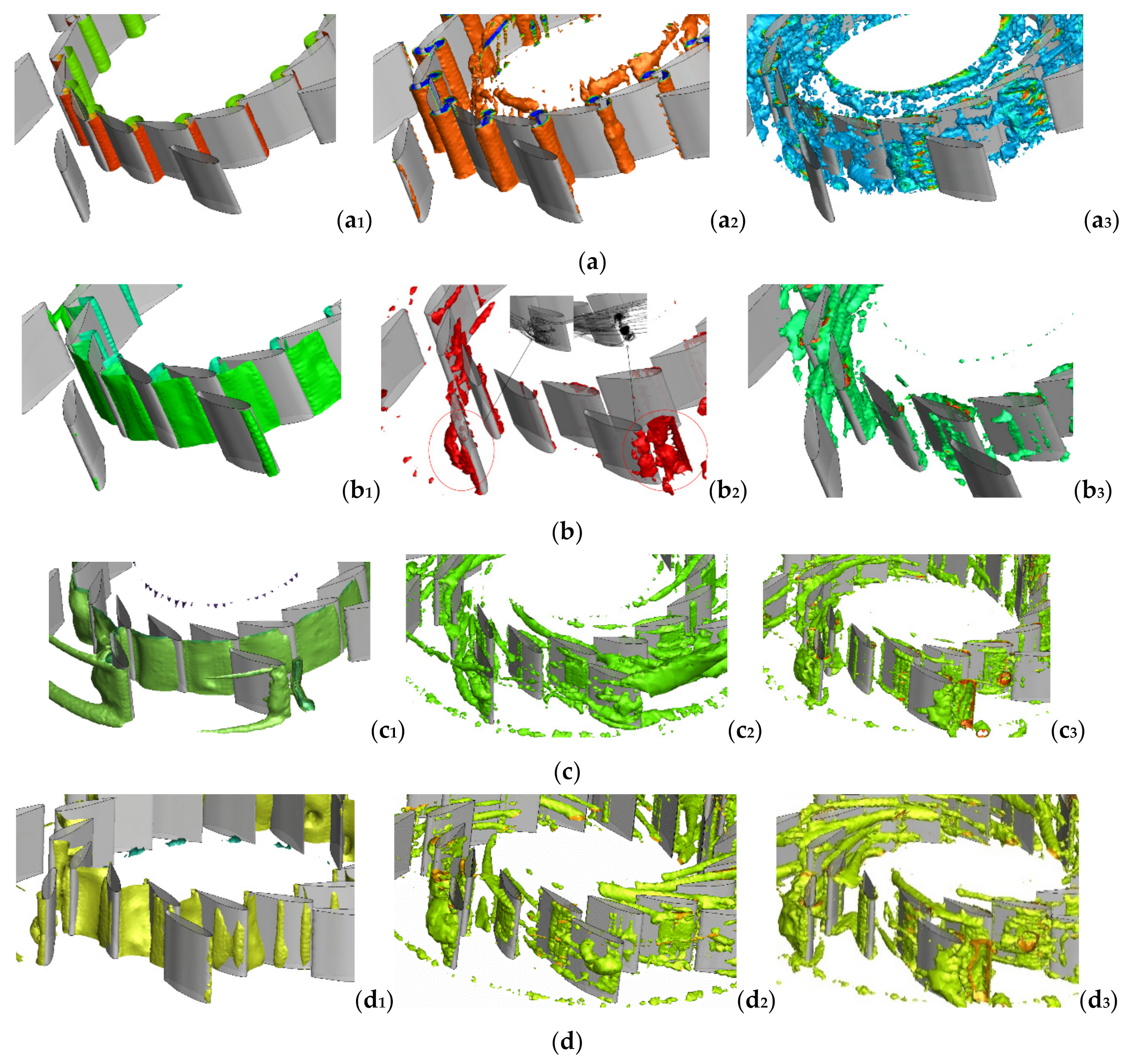
Figure 9 shows the vortex structure captured by the pressure iso-surface method, the Q criterion, and Liutex. From the pressure contour plots, it can be seen that the pressure gradient of the guide vane and runner domain dramatically changes, and the low-pressure zone is obvious under the condition of a small opening. With the decrease in the guide vane opening, the pressure in the runner domain gradually changes from symmetric to asymmetric. Because only the region with a positive Q criterion has a vortex structure, the contour plots of the Q criterion and Liutex are very similar in the four cases. With the decrease in the guide vane opening, the scale distribution of the vortex becomes increasingly wider. The value of Liutex represents the local rotation intensity of the vortex. It can be seen from the Figure 9(a3) that the vortex with higher intensity is mainly concentrated at the inlet and outlet of the runner with a larger pressure gradient. The results show the following: (1) Under the optimal condition, the steady continuous pressure flow is maintained in the blade passage, while under the condition of a small opening, the continuous and stable pressure gradient is broken and the runner blade inlet no longer meets the condition of no impact inlet. When the inlet angle of attack is too large, it causes flow separation between the blades or at the inlet of the runner crown, and the vortex enters the blade passage to form the inter-blade passage vortex. (2) Both Liutex and the Q criterion can capture the characteristics of large vortexes, but Liutex is superior to the Q criterion in capturing small vortexes. Moreover, the vortexes captured by Liutex are not strongly dependent on the threshold range, but the vortexes captured by the Q criterion are more sensitive to the change in threshold.
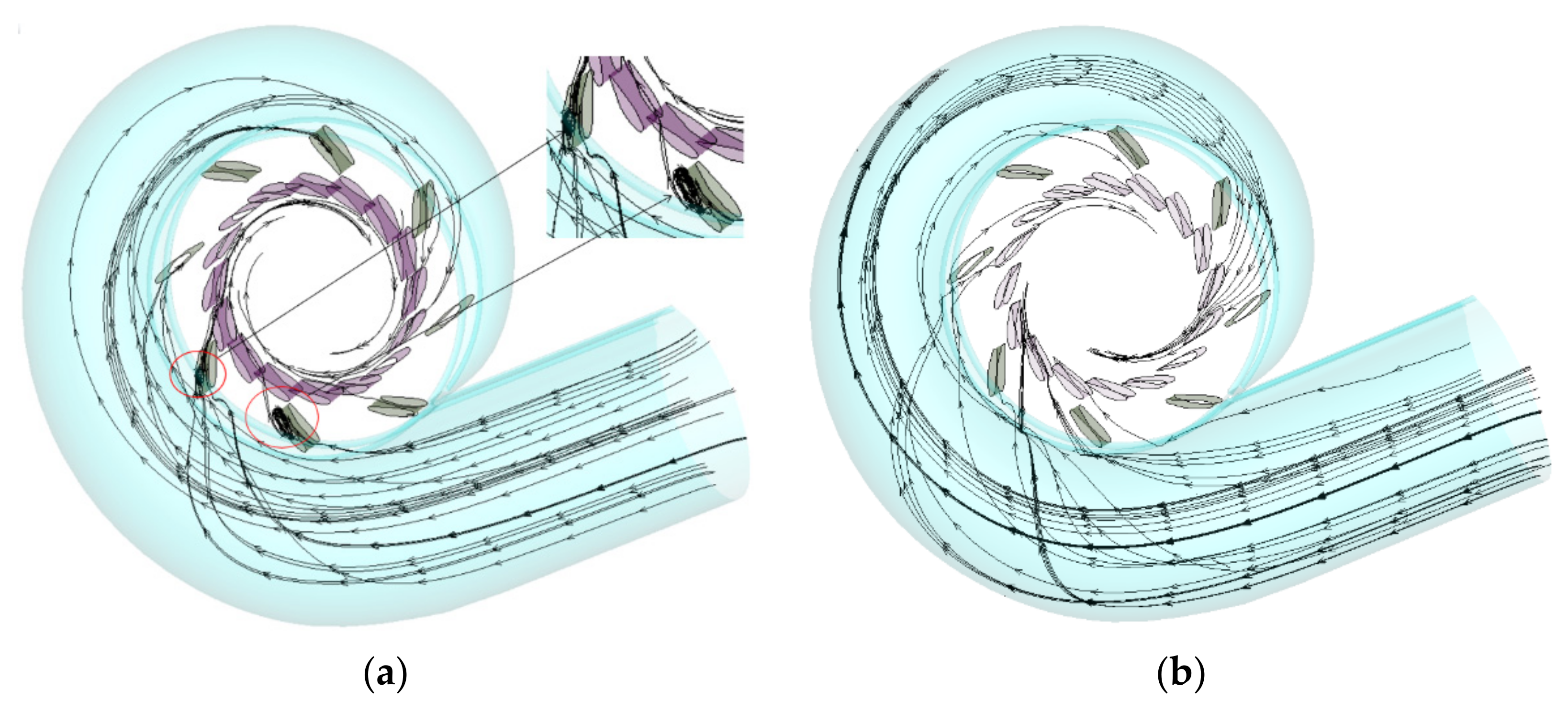
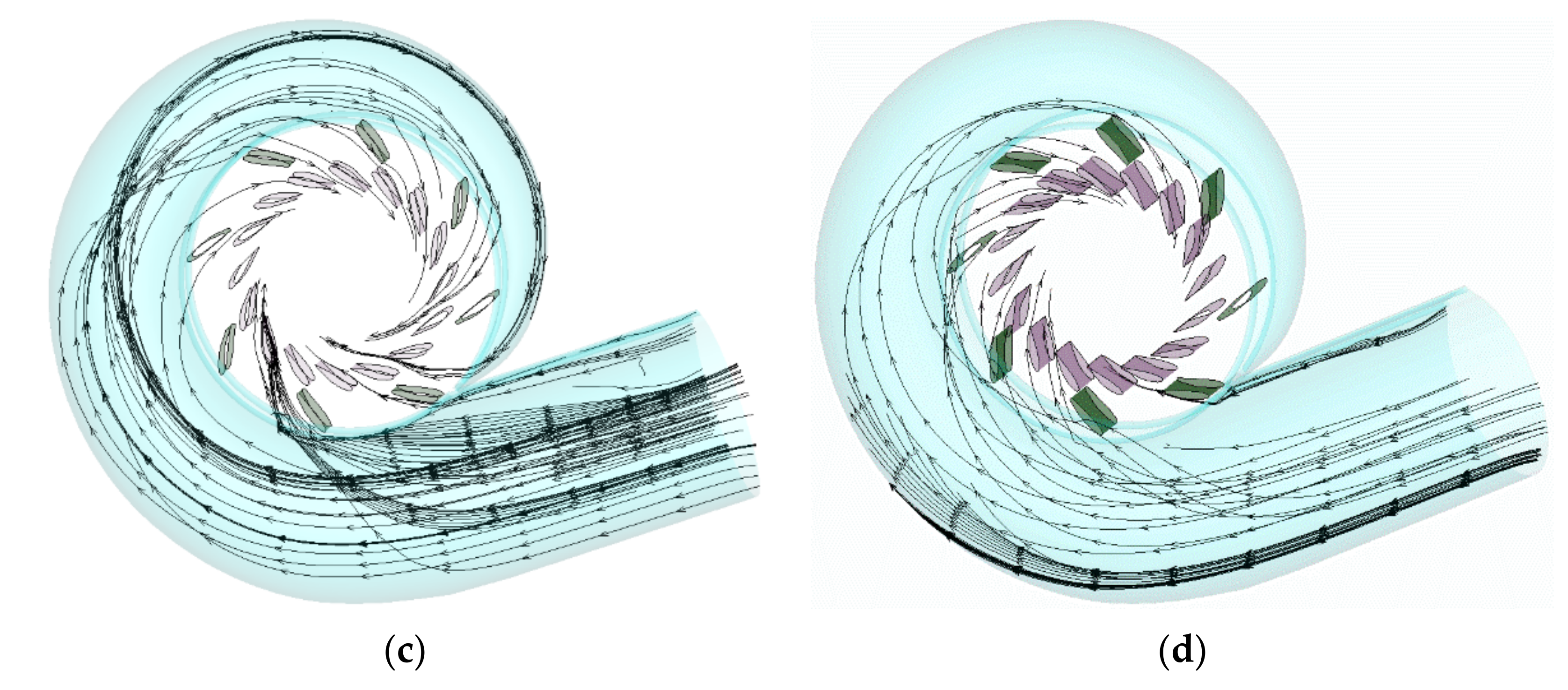
Figure 10 shows the vortex structure in the guide vanes domain. The flow field structure identified in Figure 10a,b contains mainly spanwise vortexes, and that in Figure 10c,d) contains mainly streamwise vortexes. It can be seen that the pressure iso-surface method cannot capture the vortex structure, but the difference between Liutex and the Q criterion is minor. After flowing through the guide vanes, the fluid presents a violent flow pattern. It can be seen from Figure 9 that there are vortexes with different scales in the passage from the outlet of the guide vanes to the runner, and the vortex structure in the runner zone is relatively symmetrical. As the fluid flows downstream, the concentrated vortexes separated from the guide vanes interfere with each other and their intensity decreases. They enter the runner blade passage and collide with the blade, causing flow separation, and then form vortexes of almost the same scale at the inlet of the blades, and the intensity further increases. In Figure 10(b2), the Q criterion clearly captures the existence of spanwise vortexes, which corresponds to the streamline diagram. However, it is not easy for Liutex to adjust the threshold here. It can be seen from Figure 10(a3) that due to the small opening, the vortex structure tends to be unstable, and vortexes of various scales appear, which lowers the energy conversion efficiency of the turbine. The results show the following: (1) spanwise vortexes appear only at the small opening; (2) in the case of capturing spanwise vortexes, Liutex is slightly inferior to the Q criterion.
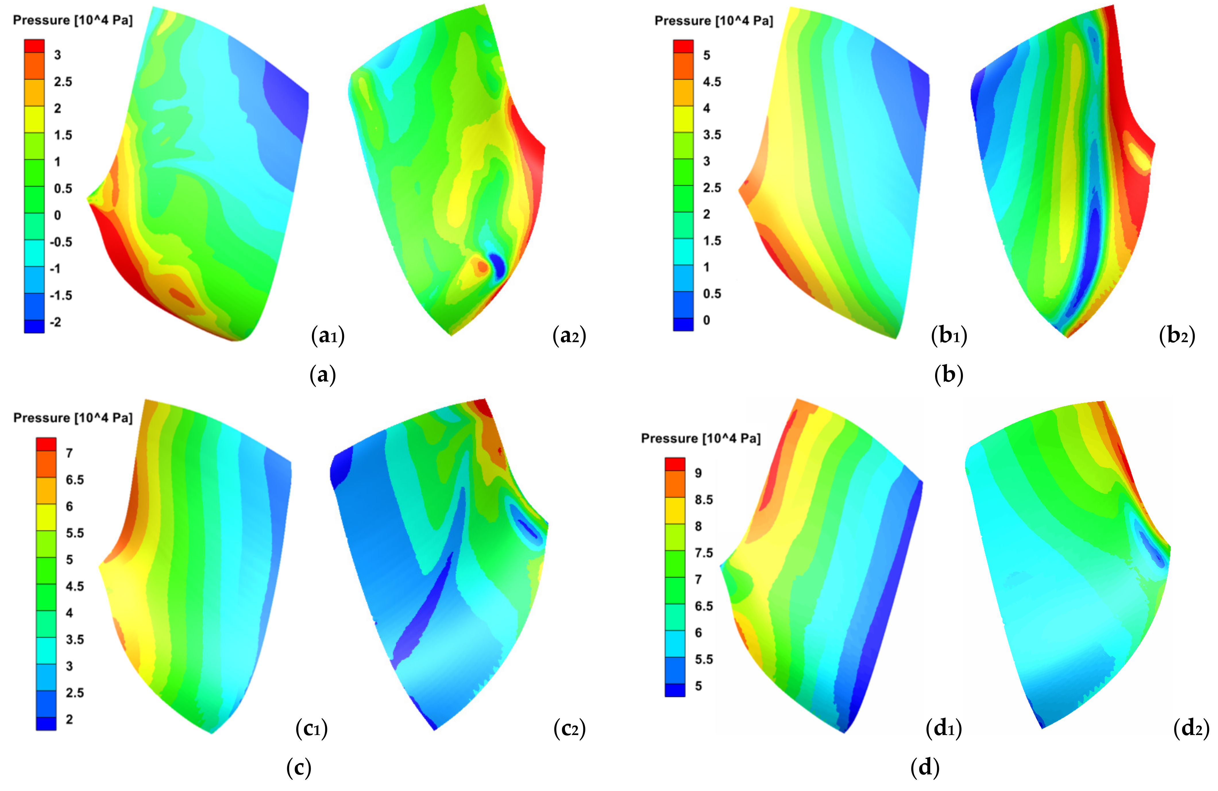
Figure 11 shows the pressure contour plot of the blade. It can be seen that the pressure distribution on the upstream surface does not change with the change in the guide vane opening, but the numerical value changes, which is consistent with the velocity and pressure distribution of the spiral case and the guide apparatus. Transverse flow and backflow lead to an obvious low-pressure zone near the runner crown. As the guide vane opening reduces, the low-pressure zone moves to the upper right corner of Figure 11. Under the four conditions, the pressure distribution on the back surface of the blade is essentially irregular under the influence of backflow and the passage vortex. Both the upstream surface and the back surface meet the requirements that the pressure decreases uniformly from the inlet to outlet and the change in the pressure gradient at the upstream surface is notably greater than that at the back surface. Moreover, the upstream pressure at each point on the entire blade surface is higher than that at the back surface. The negative pressure zone mainly appears in the connection zone between the outlet side of the back surface and the lower ring of the runner due to the influence of the upstream surface of the next blade. The flow separation and backflow are prone to emerge in the zone, which reduces the efficiency of the turbine. Moreover, cavitation can easily occur in the flow separation zone. Cavitation occurs and then causes cavitation corrosion. In severe cases, a large number of metal materials in the cavitation area are corroded, resulting in the phenomenon of blade perforation or edge falling.
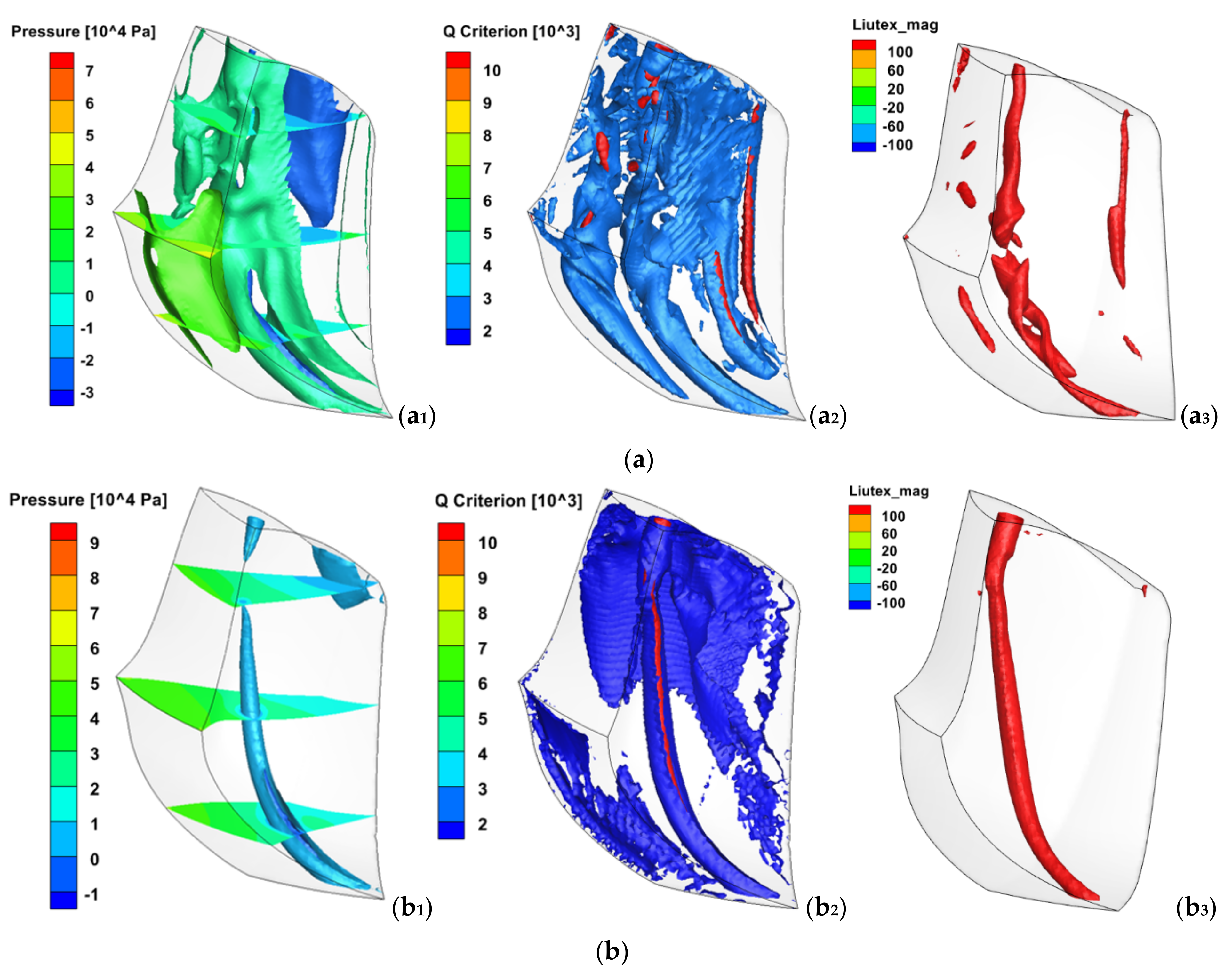
The generation mechanism of the inter-blade passage vortex is as follows: when the Francis turbine is under the small opening condition in which the fluid flows into the runner, this leads to flow separation at the inlet side of the blade because the angle of attack at the blade inlet is too large. The shape of the inter-blade passage vortex is shown in Figure 12. It can be seen from Figure 12a that clear unsteady flow occurs in the runner passage under the small opening condition. The secondary flow and vortex structure fill the whole runner and cause flow blockage, so the inter-blade passage vortex is notably disordered in this case. With the increase in the guide vane opening, the tangential velocity decreases, the radial velocity increases, and the flow pattern improves. Therefore, there is essentially no vortex in the blade passage under the optimal condition as shown in Figure 12d. As shown in Figure 12b,c, the flow pattern is neither as good as that under the optimal condition nor as chaotic as that under the small opening condition, so a complete blade passage vortex will appear. Figure 12f displays the inter-blade passage vortex observed in the same type of turbine model with a similar runner diameter. The number of guide vanes of the experimental turbine and that of the turbine in this paper is 16, and the number of runner blades is 13. Figure 12f presents the same shape as that shown in Figure 12e. The shape that resembles that shown in Figure 12e the most is that captured by Liutex, as shown in Figure 12(e3). The vortex in Figure 12(e2) captured by the Q criterion is too large, because the stretch, compression, and shear are regarded as parts of the vortex intensity in the Q criterion, which pollutes the vortex structure. The vortexes captured by the pressure iso-surface method are different from those captured by the Q criterion and Liutex. The Q criterion and the position of the inter-blade passage vortex captured by Liutex correspond to each other. The results show the following: (1) When the turbine deviates from the optimal operating condition, it can easily produce a blade passage vortex, which affects the efficient and stable operation of the turbine. (2) The vortex captured by the pressure iso-surface method cannot be well adjusted to make it complete and coherent, as shown in Figure 12(e1). With different vortex identification criteria, the selection of the threshold value is vital, directly affecting the display shape of the vortex. Therefore, in vortex identification processing, it is necessary to determine the optimal value by undergoing many trials combined with experimental results, which verifies again that the Q criterion is sensitive to changes in the threshold value; the threshold value of Liutex is one or two orders of magnitude less than that of the Q criterion. That is the advantage of Liutex. (3) Liutex has less miscellaneous vortices in the capture of the inter-blade passage vortex, and a whole inter-blade passage vortex can be observed, which is of great significance in the analysis of the formation and development of the inter-blade passage vortex.
3.3. Identification and Comparison of Vortex Rope in Draft Tube under Various Upstream Disturbances
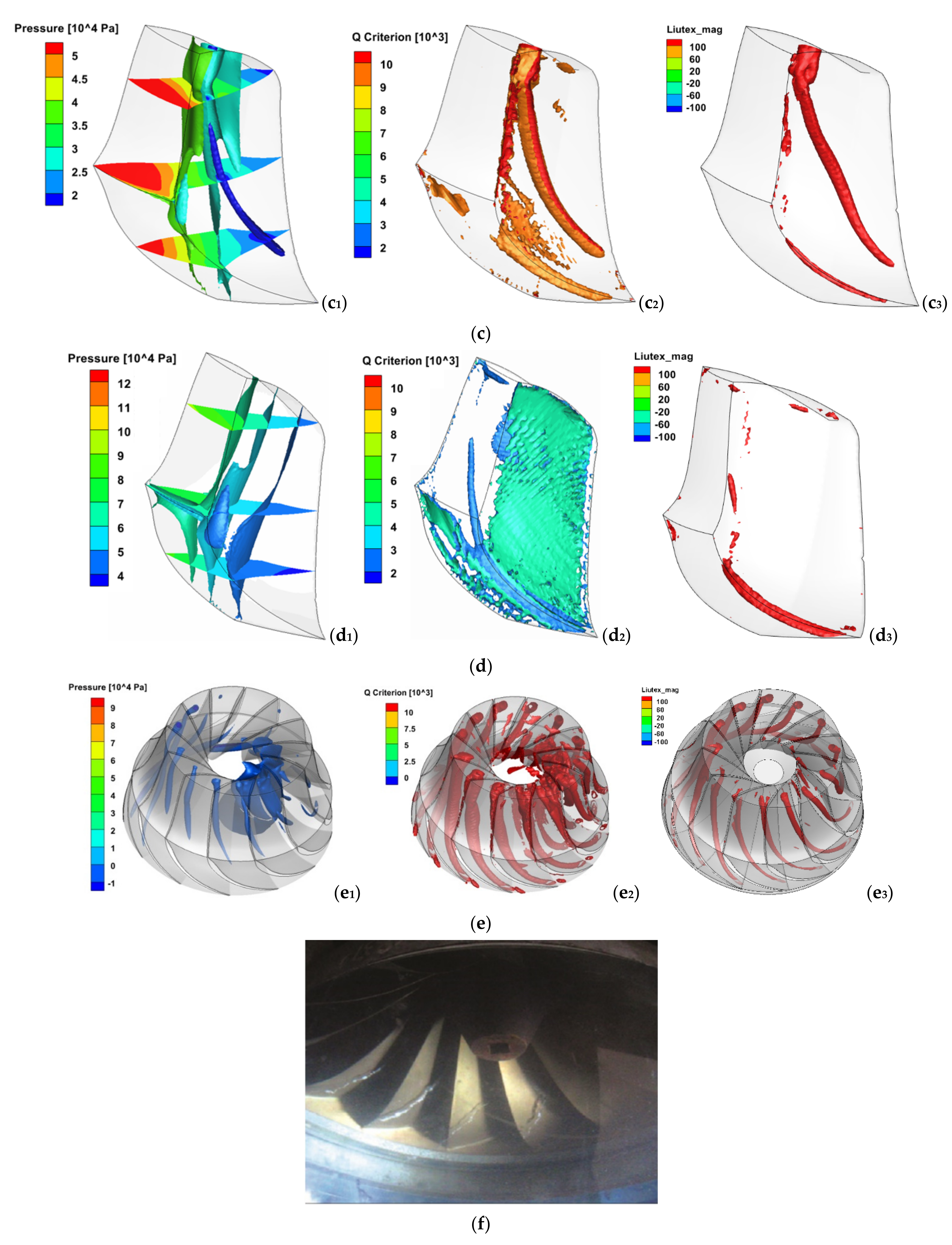
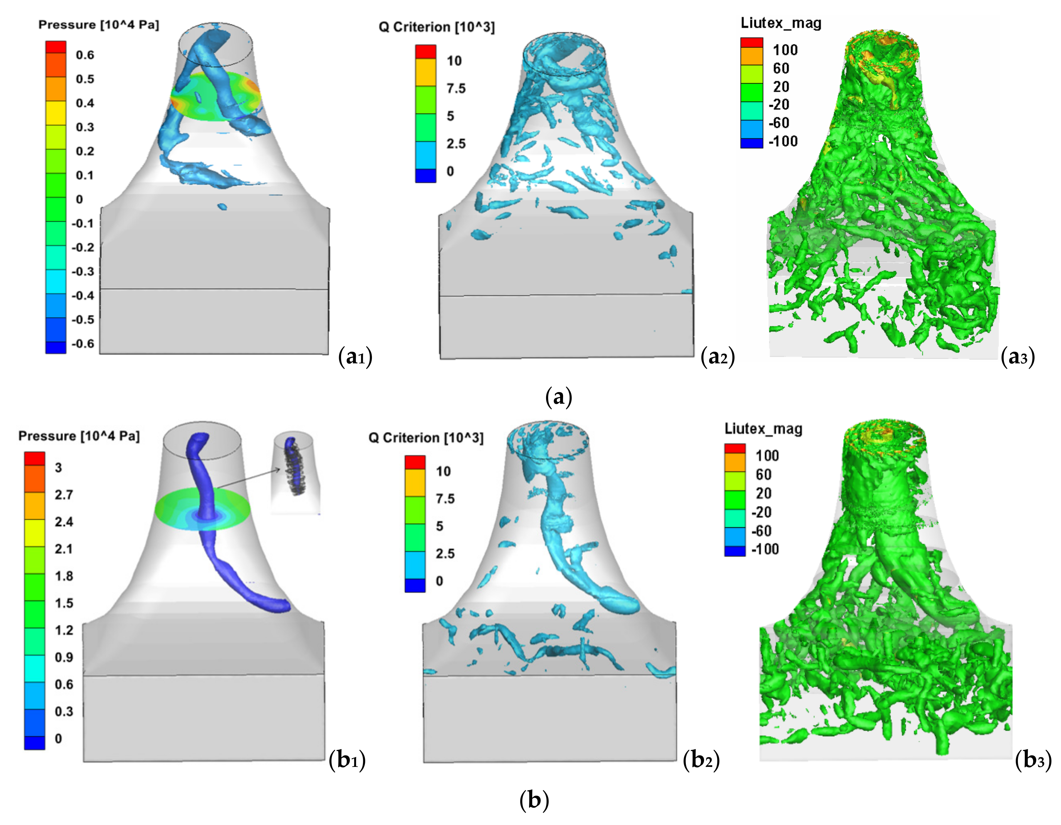
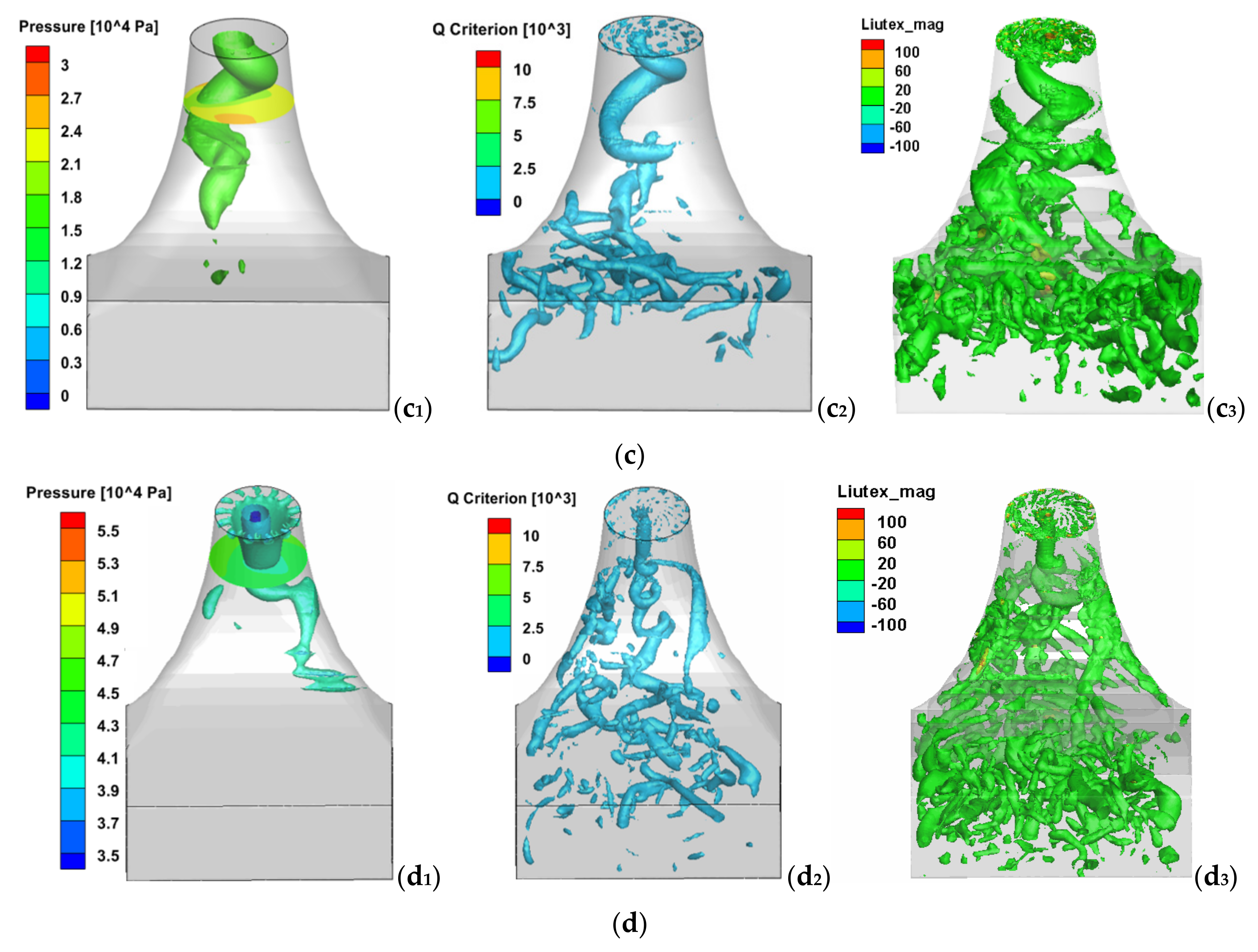
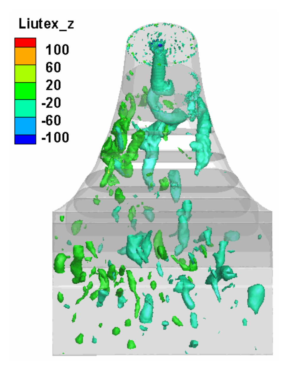
When the fluid flows out from the runner outlet, it is thrown out close to the draft tube wall in the circumferential velocity dominant flow state, resulting in the formation of a low-pressure cavity on the draft tube cross-section after fluid diversion, namely, the draft tube vortex rope. After flowing out of the runner, these vortexes with high turbulent kinetic energy continue to evolve, and the large-scale vortexes further exchange energy with small-scale vortexes, which induces more new small-scale vortexes that fill the downstream passage and finally flow out of the draft tube. With the decrease in the guide vane opening, the shape and position of the vortex rope in the draft tube also change. When the opening is α = 26.17 mm, it reaches the maximum. As the opening continues to reduce, the flow pattern becomes more disordered, and the interaction between large and small vortexes increases, which leads to the rupture of the hollow vortex rope. The vortexes and streamlines captured by the pressure iso-surface method in Figure 13(b1) correspond to each other, but their integrity and coherence are low. The Q criterion is generally consistent with the vortex rope captured by Liutex, but the ability of the Q criterion to capture small vortexes is slightly insufficient. It can be clearly observed in Figure 14 that the hollow vortex rope of the draft tube under the four conditions is mainly composed of a flow direction vortex.
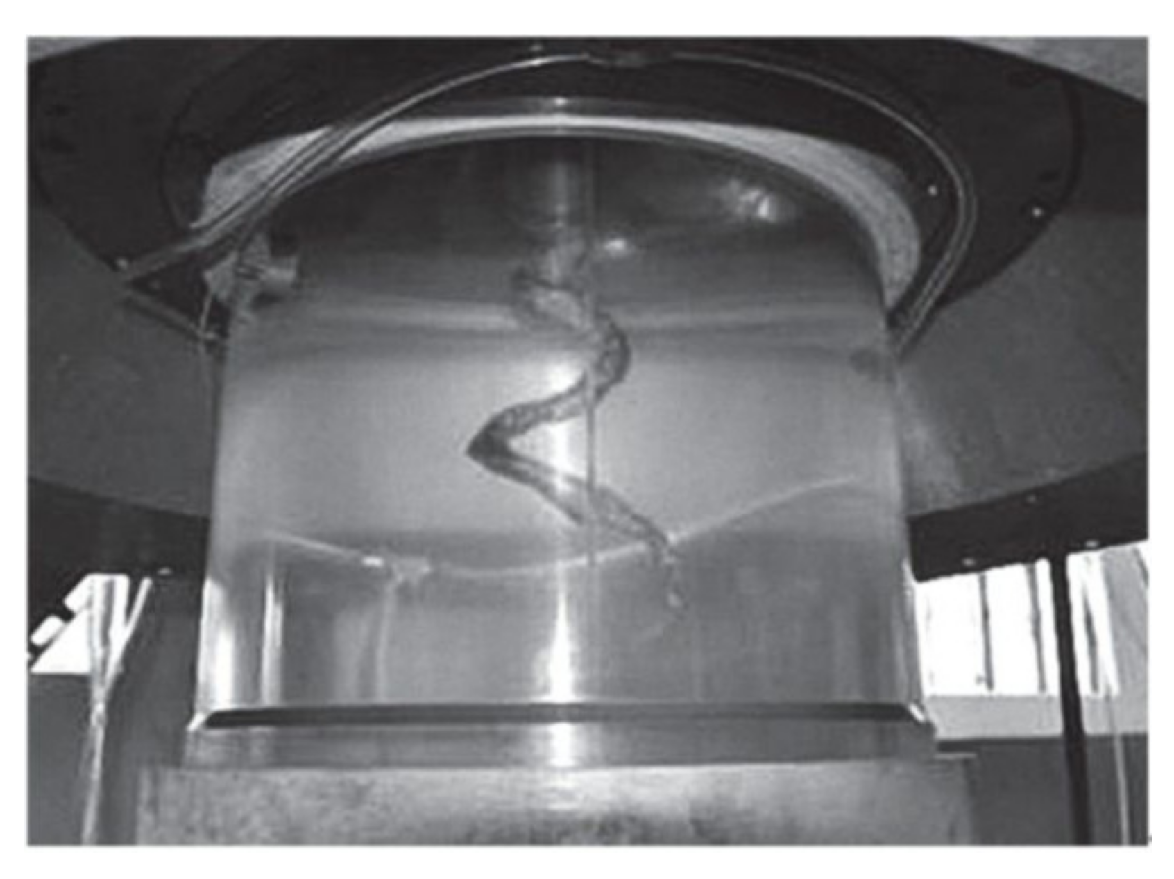
Figure 15, obtained by experimental observation, displays the Francis turbine model with a similar runner diameter in this paper. The core of the vortex rope is eccentrically located on the surface of the runner cone. The vortex rope is in a conical spiral shape, and the tail of the vortex rope gradually becomes thinner until it disappears. The shape is essentially the same as that shown in Figure 14. The results suggest the following: (1) The patterns of the draft tube vortex rope are different in the four conditions, and it is not true that the smaller the opening, the larger the hollow vortex rope of the draft tube. When the opening of the guide vane is less than a certain value, the flow state becomes more disordered, the vortexes of the draft tube affect each other, and the vortex rope of the draft tube breaks. The turbulence of the flow field and the mutual interference between vortexes are able to destroy the vortex rope of the draft tube, seriously affecting the stable operation of the turbine. (2) The vortex captured by the pressure iso-surface method will break up in an untimely manner, and the vortex band captured by the Q criterion generally corresponds to that captured by Liutex. It is verified again that the dependence of the Q criterion on the threshold value is far greater than that of Liutex, and the ability of Liutex to capture small vortexes is slightly greater than that of the Q criterion. The application effect of Liutex in hydraulic machinery is good.
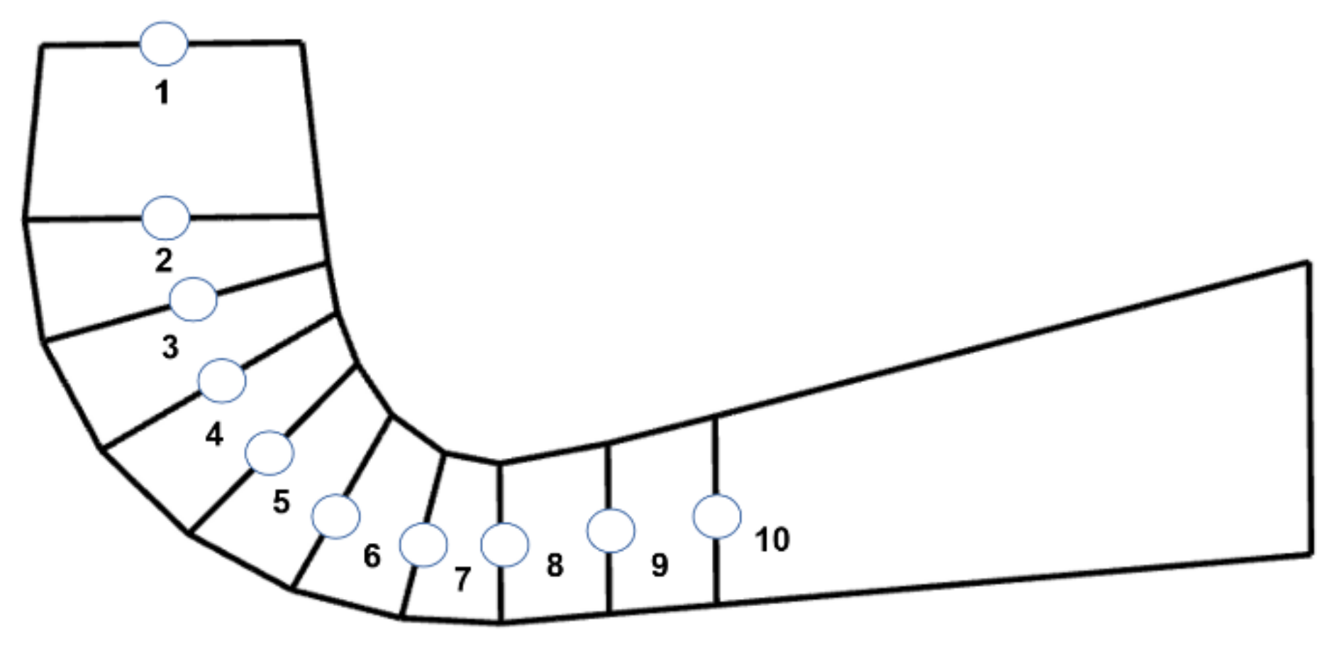
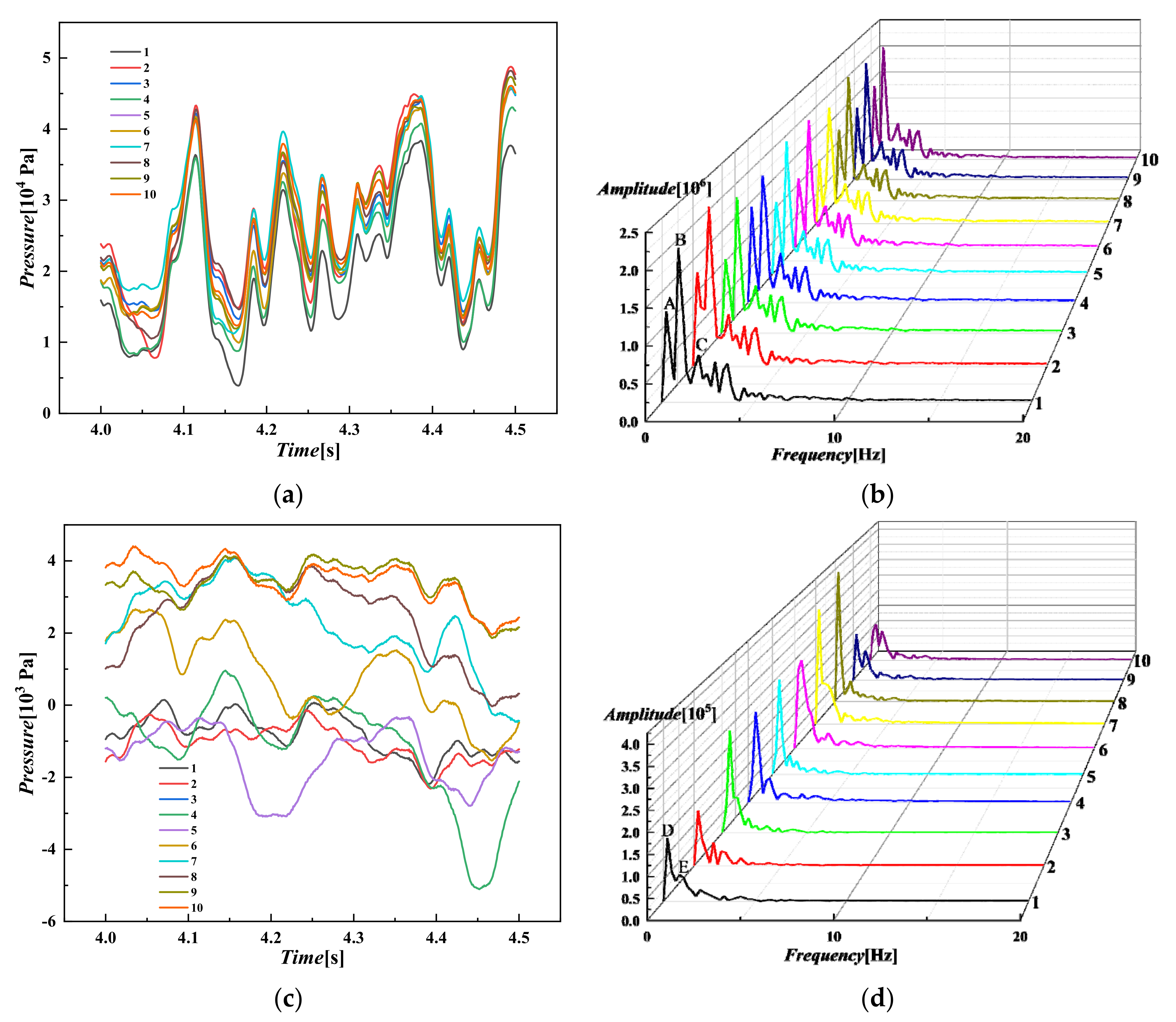
Figure 16 shows the location of monitoring points in the draft tube. Figure 17 shows a time domain diagram and frequency domain diagram of pressure fluctuation in the draft tube. Under the optimal condition, the energy components of pressure pulsation are essentially the same, and they are mainly low frequency. There is a low-frequency pulsation with a main frequency of about 0.9 Hz, which is close to 0.1 times the conversion frequency of 10 Hz. As can be seen from Table 3A–C, in the draft tube area, the primary frequency, secondary frequency, and tertiary frequency are 0.22178, 0.88712, and 1.99602, respectively, and the transmission of the low-frequency pressure wave is stable, indicating that the water flow condition in the draft tube under normal working conditions is somewhat poor. In this case, resonance can easily occur. It can be clearly observed in Table 3D,E and Figure 17d that the frequency and amplitude of the small opening condition are high and low, respectively, making it a notably chaotic condition, and this is similar to the change in the vortex structure under the small opening condition. Under the small opening, the amplitude of the bending shaft section is larger than that of other areas of the draft tube. The flow of the water body is extremely disordered, so paying attention to the flow characteristics of water flow under the small opening is the main problem in the research and development of the Francis turbine.
4. Conclusions
In this paper, large-eddy simulation and sliding grid technology are used to study the vortex structure characteristics in the passage of a Francis turbine under four types of openings. Not only are the distribution characteristics of velocity and pressure in the passage obtained, but the Q criterion and Liutex vortex identification methods are compared. The results are as follows: the small opening condition causes great upstream disturbances in the passage and an increase in tangential velocity, in which the flow path of the fluid—after the guide vane is lengthened and the interaction among the wake vortexes behind the guide vane is strengthened—results in flow separation and other hydraulic instability phenomena as well as the inter-blade passage vortexes. The inter-blade passage vortexes exacerbate the uneven distribution of blade pressure, and the instability and rupture easily produce local low-frequency dynamic stress, leading to the fatigue failure of the blade at the connection of the outlet edge and the lower ring of the runner. The turbulence of the flow field and the mutual interference between vortexes are able to destroy the vortex rope of the draft tube, seriously affecting the stable operation of the turbine. In capturing small vortexes, Liutex is superior to the Q criterion and is not highly dependent on the threshold value. Liutex has the advantages of indicating rotational strength and the direction of the rotation axis, but its ability to capture spanwise vortexes requires further improvement.
Author Contributions
Conceptualization, T.G. and L.X.; methodology, L.X.; software, L.X.; validation, T.G., L.X. and W.W.; formal analysis, L.X.; investigation, L.X.; resources, L.X.; data curation, L.X.; writing—original draft preparation, L.X.; writing—review and editing, T.G. and W.W.; visualization, L.X.; supervision, T.G. and W.W.; project administration, T.G.; funding acquisition, T.G. All authors have read and agreed to the published version of the manuscript.
Funding
This work was financially supported by National Natural Science Foundation of China (NSFC) (Grants no. 51969009 and 52069010).
Institutional Review Board Statement
Not applicable.
Informed Consent Statement
Not applicable.
Data Availability Statement
The study did not report any data.
Conflicts of Interest
The authors declare no conflict of interest.
Nomenclature
| Filtered velocity in i direction | |
| Filtered pressure | |
| Subgrid stress | |
| Fluid density | |
| Kinematic viscosity | |
| Lij | Leonard stress, which stands for the interaction between large scale vortexes |
| Cij | Cross stress, standing for the interaction between large-scale vortexes and small-scale vortexes |
| Rij | Reynolds stress, standing for the interaction between small-scale vortexes |
| Model parameters of WALE subgrid model | |
| Filter size | |
| Strain rate tensor |
References
- Müller, A.; Favrel, A.; Landry, C.; Avellan, F. Fluid–structure interaction mechanisms leading to dangerous power swings in Francis turbines at full load. J. Fluids Struct. 2017, 69, 56–71. [Google Scholar] [CrossRef]
- Liu, D.; Liu, X.; Zhao, Y. Experimental Investigation of inter-blade vortices in a model Francis turbine. Chin. J. Mech. Eng. 2017, 30, 854–865. [Google Scholar] [CrossRef]
- Ruan, H.; Liao, W.; Gong, H.; Zhao, Y.; Luo, X. Dynamic analysis of high-specific-speed Francis turbine runner in channel vortices condition. J. Hydroelectr. Eng. 2015, 34, 25–31. [Google Scholar]
- Luo, X.W.; Ji, B.; Tsujimoto, Y. A review of cavitation in hydraulic machinery. J. Hydrodyn. 2016, 28, 335–358. [Google Scholar] [CrossRef]
- Wang, Y.Q.; Gui, N. A review of the third-generation vortex identification method and its applications. Chin. J. Hydrodyn. 2019, 34, 413–429. [Google Scholar]
- Guo, T.; Zang, L.X. Numerical study on turbulence characteristics in francis turbine under small opening condition. Eng. Mech. 2015, 32, 222–230. [Google Scholar]
- Guo, T.; Zhang, L.X. Numerical Study of Swirling Flow Fields in Francis Turbine under Small Opening Condition. Trans. Chin. Soc. Agric. Mach. 2014, 45, 112–118. [Google Scholar]
- Zhang, L.X.; Wang, W.Q.; Guo, Y.K. Intrinsic features of turbulent flow in strongly 3-D skew blade passage of a francis turbine 11 Project supported by the National Natural Science Foundation of China (Grant Nos. 50579025, 90210005). J. Hydrodyn. 2007, 19, 92–99. [Google Scholar] [CrossRef]
- Wang, W.Q.; Zhang, L.X.; Yan, Y. Study on Turbulence Features Near an Oscillating Curved Wall. J. Hydrodyn. 2007, 19, 255–263. [Google Scholar] [CrossRef]
- Wang, W.Q.; Zhang, L.X.; Yan, Y.; Guo, Y.K. Large-Eddy Simulation of Turbulent Flow Considering Inflow Wakes in a Francis Turbine Blade Passage. J. Hydrodyn. 2007, 19, 201–209. [Google Scholar] [CrossRef]
- Jafarzadeh, J.H.; Maddahian, R.; Cervantes, M.J. Optimization of axial water injection to mitigate the Rotating Vortex Rope in a Francis turbine. Renew. Energy 2021, 175, 214–231. [Google Scholar] [CrossRef]
- Favrel, A.; Gomes Pereira Junior, J.; Müller, A.; Landry, C.; Yamamoto, K.; Avellan, F. Swirl number based transposition of flow-induced mechanical stresses from reduced scale to full-size Francis turbine runners. J. Fluids Struct. 2020, 94, 102956. [Google Scholar] [CrossRef]
- Tania, M.A.; Waldir, D.O.; Ramiro, G.R. Francis turbine draft tube parameterization and analysis of performance characteristics using CFD techniques. Renew. Energy 2018, 127, 114–124. [Google Scholar]
- Nahale, S.; Reza, M.; Michel, J. Cervantes. Investigation of Rotating Vortex Rope formation during load variation in a Francis turbine draft tube. Renew. Energy 2020, 151, 238–254. [Google Scholar]
- Muhirwa, A.; Li, B.; Su, W.T.; Liu, Q.Z.; Binama, M.; Wu, J.; Cai, W.H. Investigation on mutual traveling influences between the draft tube and upstream components of a Francis turbine unit. Renew. Energy 2020, 162, 973–992. [Google Scholar] [CrossRef]
- Chong, M.S.; Perry, A.E.; Cantwell, B.J. A general classification of three-dimensional flow fields. Phys. Fluids A Fluid Dyn. 1990, 2, 765–777. [Google Scholar] [CrossRef]
- Zhang, Y.N.; Wang, X.Y.; Liu, C.Q. Comparisons and analyses of vortex identification between Omega method and Q criterion. J. Hydrodyn. 2019, 31, 224–230. [Google Scholar] [CrossRef]
- Jeong, J.; Hussain, F. On the identification of a vortex. J. Fluid Mech. 1995, 285, 69–94. [Google Scholar] [CrossRef]
- Zhou, J.; Adrian, R.J.; Balachandar, S.; Kendall, T.M. Mechanisms for generating coherent packets of hairpin vortices in channel flow. J. Fluid Mech. 1999, 387, 353–396. [Google Scholar] [CrossRef]
- Dong, X.R. Theoretical and Numerical Study on Identification Method and Mechanism of Vortex Structure. Ph.D. Thesis, Nanjing University of Technology, Nanjing, China, 2019. [Google Scholar]
- Liu, C.Q. Liutex-third generation of vortex definition and identification methods. Acta Aerodyn. Sin. 2020, 38, 413–431+478. [Google Scholar]
- Yu, Y.F.; Shrestha, P.; Alvarez, O.; Nottage, C.; Liu, C.Q. Investigation of correlation between vorticity, Q, λci, λ2, Δ and Liutex. Comput. Fluids 2021, 225, 104977. [Google Scholar] [CrossRef]
- Shrestha, P.; Nottage, C.; Yu, Y.F.; Alvarez, O.; Liu, C.Q. Stretching and shearing contamination analysis for Liutex and other vortex identification methods. Adv. Aerodyn. 2021, 3, 8. [Google Scholar] [CrossRef]
- Charkrit, S.; Shrestha, P.; Liu, C.Q. Liutex core line and POD analysis on hairpin vortex formation in natural flow transition. J. Hydrodyn. 2020, 32, 1109–1121. [Google Scholar] [CrossRef]
- Zhang, Y.N.; Liu, K.H.; Xian, H.Z.; Du, X.Z. A review of methods for vortex identification in hydroturbines. Renew. Sustain. Energy Rev. 2018, 81, 1269–1285. [Google Scholar] [CrossRef]
- Zhang, Y.N.; Qiu, X.; Chen, F.P.; Liu, K.H.; Dong, X.R.; Liu, C.Q. A selected review of vortex identification methods with applications. J. Hydrodyn. 2018, 30, 767–779. [Google Scholar] [CrossRef]
- Chen, T.; Zheng, X.H.; Zhang, Y.N.; Li, S.C. Influence of upstream disturbance on the draft-tube flow of Francis turbine under part-load conditions. J. Hydrodyn. 2018, 30, 131–139. [Google Scholar] [CrossRef]
- Sun, L.G.; Guo, P.C.; Luo, X.Q. Visualization investigation into precessing vortex rope in Francis turbine draft tube based on several vortex identification criterions. Chin. J. Hydrodyn. 2019, 34, 779–787. [Google Scholar]
- Guo, P.C.; Sun, L.G.; Luo, X.Q. Flow characteristic investigation into inter-blade vortex for Francis turbine. Trans. Chin. Soc. Agric. Eng. 2019, 35, 43–51. [Google Scholar]
- Yu, Z.F.; Yan, Y.; Wang, W.Q.; Liu, X.S. Entropy production analysis for vortex rope of a Francis turbine using hybrid RANS/LES method. Int. Commun. Heat Mass Transf. 2021, 127, 105494. [Google Scholar] [CrossRef]
- Li, D.Y.; Wang, H.J.; Qin, Y.L.; Han, L.; Wei, X.Z.; Qin, D.Q. Entropy production analysis of hysteresis characteristic of a pump-turbine model. Energy Convers. Manag. 2017, 149, 175–191. [Google Scholar] [CrossRef]
- Hou, H.C.; Zhang, Y.X.; Li, Z.L.; Jiang, T.; Zhang, J.Y.; Xu, C. Numerical analysis of entropy production on a LNG cryogenic submerged pump. J. Nat. Gas Sci. Eng. 2016, 36, 87–96. [Google Scholar] [CrossRef]
- Laouari, A.; Ghenaiet, A. Investigation of steady and unsteady cavitating flows through a small Francis turbine. Renew. Energy 2021, 172, 841–861. [Google Scholar] [CrossRef]
- Gyanendra, T.; Jitendra, K.; Vishnu, P.; Vivek, K.P. Derivation of cavitation characteristics of a 3MW prototype Francis turbine through numerical hydrodynamic analysis. Mater. Today Proc. 2020, 26, 1439–1448. [Google Scholar]
- Yang, J.; Zhou, L.J.; Wang, Z.W. Numerical investigation of the cavitation dynamic parameters in a Francis turbine draft tube with columnar vortex rope. J. Hydrodyn. 2019, 31, 931–939. [Google Scholar] [CrossRef]
- Zhang, Z.; Yu, Z.D.; Gao, H.B.; Cheng, N.; Wang, J.X. Research on the cavitation characteristic improvement of impellers of HL220 turbine. Environ. Earth Sci. 2019, 78, 1–9. [Google Scholar] [CrossRef]
- Wang, S.; Zhang, L.J.; Yin, G.J.; Guan, C.N. Research on Unsteady Hydraulic Features of a Francis Turbine and a Novel Method for Identifying Pressure Pulsation Transmission Path. Water 2019, 11, 1216. [Google Scholar] [CrossRef] [Green Version]
- Li, D.; Fu, X.; Wang, H.; Zhao, R.; Wei, X. Evolution mechanism of a prototype pump turbine after pump power-off. Phys. Fluids 2021, 33, 106109. [Google Scholar] [CrossRef]
- Li, D.Y.; Yu, L.; Yan, X.Y.; Wang, H.J.; Shi, Q.; Wei, X.Z. Runner cone optimization to reduce vortex rope-induced pressure fluctuations in a Francis turbine. Sci. China Technol. Sci. 2021, 64, 1953–1970. [Google Scholar] [CrossRef]
- Cheng, H.; Zhou, L.J.; Zhao, Y.Z. Very large eddy simulation of the vortex rope in the draft tube of Francis turbine. IOP Conf. Ser. Earth Environ. Sci. 2019, 240, 022001. [Google Scholar] [CrossRef]
- Doussot, F.; Balarac, G.; Brammer, J.; Laurant, Y.; Métais, O. RANS and LES Simulations at Partial Load in Francis Turbines: Three Dimensional Topology and Dynamic Behaviour of Inter Blade Vortices. Int. J. Fluid Mach. Syst. 2020, 13, 12–20. [Google Scholar] [CrossRef]
- Altimemy, M.; Attiya, B.; Daskiran, C.; Liu, I.H.; Oztekin, A. Mitigation of flow-induced pressure fluctuations in a Francis turbine operating at the design and partial load regimes—LES simulations. Int. J. Heat Fluid Flow 2019, 79, 108444. [Google Scholar] [CrossRef]
- Trivedi, C. Time-dependent inception of vortex rings in a Francis turbine during load variation: Large eddy simulation and experimental validation. J. Hydraul. Res. 2020, 58, 790–806. [Google Scholar] [CrossRef]
- Chirag, T.; Igor, I.; Ole, G.D.; Zoran, M.; Fredrik, E.; Henning, L. Investigation of a Francis turbine during speed variation: Inception of cavitation. Renew. Energy 2020, 166, 147–162. [Google Scholar]
Figure 1.
Computational domain of the Francis turbine. (a) Whole computing domain for Francis turbine; (b) Real view of the prototype Francis turbine; (c) Spiral casing; (d) Stay/guide vanes; (e) Runner blades; (f) Draft tube.
Figure 1.
Computational domain of the Francis turbine. (a) Whole computing domain for Francis turbine; (b) Real view of the prototype Francis turbine; (c) Spiral casing; (d) Stay/guide vanes; (e) Runner blades; (f) Draft tube.

Figure 2.
Meshing of runner and stay/guide vanes for Francis turbine.

Figure 3.
Blade’s y plus for Francis turbine.

Figure 4.
A551-35 model comprehensive characteristic curve.

Figure 5.
Physical meaning of α.

Figure 6.
Flow line diagram of spiral case and guide apparatus. (a) α = 13.50 mm (small opening condition); (b) α = 26.17 mm; (c) α = 38.05 mm; (d) α = 48.74 mm (optimal condition).
Figure 6.
Flow line diagram of spiral case and guide apparatus. (a) α = 13.50 mm (small opening condition); (b) α = 26.17 mm; (c) α = 38.05 mm; (d) α = 48.74 mm (optimal condition).


Figure 7.
Guide apparatus of instantaneous velocity and means pressure. (a) α = 13.50 mm (small opening condition): (a1) Velocity contour plot (m/s), (a2) Pressure contour plot (Pa); (b) α = 26.17 mm: (b1) Velocity contour plot (m/s), (b2) Pressure contour plot (Pa); (c) α = 38.05 mm: (c1) Velocity contour plot (m/s), (c2) Pressure contour plot (Pa); (d) α = 48.74 mm (optimal condition): (d1) Velocity contour plot (m/s), (d2) Pressure contour plot (Pa).


Figure 8.
Comparison of pressure and velocity with the increasing relative diameter at meridional section of spiral case. (a) Velocity curve; (b) Pressure curve.
Figure 8.
Comparison of pressure and velocity with the increasing relative diameter at meridional section of spiral case. (a) Velocity curve; (b) Pressure curve.

Figure 9.
Meridian section of guide vane and runner domain. (a) α = 13.50 mm (small opening condition): (a1) Pressure (Pa), (a2) Q criterion, (a3) Liutex; (b) α = 26.17 mm: (b1) Pressure (Pa), (b2) Q criterion, (b3) Liutex; (c) α = 38.05 mm: (c1) Pressure (Pa), (c2) Q criterion, (c3) Liutex; (d) α = 48.74 mm (optimal condition): (d1) Pressure (Pa), (d2) Q criterion, (d3) Liutex.


Figure 10.
Vortexes in guide vanes. (a) α = 13.50 mm (small opening condition): (a1) Pressure iso-surface method, (a2) Q criterion, (a3) Liutex; (b) α = 26.17 mm: (b1) Pressure iso-surface method, (b2) Q criterion (b3) Liutex; (c) α = 38.05 mm: (c1) Pressure iso-surface method, (c2) Q criterion, (c3) Liutex; (d) α = 48.74 mm (optimal condition): (d1) Pressure iso-surface method, (d2) Q criterion, (d3) Liutex.

Figure 11.
Blade contour plot at runner. (a) α = 13.50 mm (small opening condition): (a1) Upstream surface (Pa), (a2) Back surface (Pa); (b) α = 26.17 mm: (b1) Upstream surface (Pa), (b2) Back surface (Pa); (c) α = 38.05 mm: (c1) Upstream surface (Pa), (c2) Back surface (Pa); (d) α = 48.74 mm (optimal condition): (d1) Upstream surface (Pa), (d2) Back surface (Pa).

Figure 12.
Inter-blade passage vortex. (a) α = 13.50 mm (small opening condition): (a1) Pressure iso-surface method, (a2) Q criterion, (a3) Liutex; (b) α = 26.17 mm: (b1) Pressure iso-surface method, (b2) Q criterion, (b3) Liutex; (c) α = 38.05 mm: (c1) Pressure iso-surface method, (c2) Q criterion, (c3) Liutex; (d) α = 48.74 mm (optimal condition): (d1) Pressure iso-surface method, (d2) Q criterion, (d3) Liutex; (e) Inter-blade passage vortex of runner (α = 26.17 mm): (e1) Pressure iso-surface method, (e2) Q criterion, (e3) Liutex; (f) Experimental observation of turbine with runner diameter of 0.35 m [29].


Figure 13.
Vortex rope in draft tube. (a) α = 13.50 mm (small opening condition): (a1) Pressure iso-surface method, (a2) Q criterion, (a3) Liutex; (b) α = 26.17 mm: (b1) Pressure iso-surface method, (b2) Q criterion, (b3) Liutex; (c) α = 38.05 mm: (c1) Pressure iso-surface method, (c2) Q criterion, (c3) Liutex; (d) α = 48.74 mm (optimal condition): (d1) Pressure iso-surface method, (d2) Q criterion, (d3) Liutex.


Figure 14.
Analysis of streamwise vortex rope.

Figure 15.
Experimental observation of vortex rope in draft tube of a turbine with a runner diameter of 0.35 m [28].
Figure 15.
Experimental observation of vortex rope in draft tube of a turbine with a runner diameter of 0.35 m [28].

Figure 16.
Draft tube.

Figure 17.
Time domain diagram and frequency domain diagram of pressure fluctuation. (a) time domain diagram (optimal condition); (b) frequency domain diagram (optimal condition); (c) time domain diagram (small opening condition); (d) frequency domain diagram (small opening condition).
Figure 17.
Time domain diagram and frequency domain diagram of pressure fluctuation. (a) time domain diagram (optimal condition); (b) frequency domain diagram (optimal condition); (c) time domain diagram (small opening condition); (d) frequency domain diagram (small opening condition).


Table 1.
Geometry parameters.
| Parameter | Value |
|---|---|
| Number of guide vanes | 16 |
| Number of runner blades | 13 |
| Inlet diameter of spiral casing | 540 mm |
| Outlet length of draft tube | 1410 mm |
| Height of guide vanes | 118 mm |
| Diameter of runner | 430 mm |
Table 2.
Details of working conditions.
| Condition | α/mm | Angle of Attack/° | Q11/(m3/s) | η | Pn% |
|---|---|---|---|---|---|
| A (small opening condition) | 13.5 | 8 | 0.270 | 0.31 | 8 |
| B | 26.17 | 16 | 0.660 | 0.82 | 49 |
| C | 38.05 | 24 | 0.975 | 0.91 | 80 |
| D (optimal condition) | 48.74 | 32 | 1.197 | 0.93 | 99 |
Table 3.
Frequency of key point (Hz).
| Key Point | Optimal Condition | Small Opening Condition | |||
|---|---|---|---|---|---|
| A | B | C | D | E | |
| 1 | 0.22178 | 0.88712 | 1.99602 | 0.22178 | 0.88712 |
| 2 | 0.22178 | 1.10890 | |||
| 3 | 0.44356 | 0.88712 | |||
| 4 | 0.22178 | 0.88712 | |||
| 5 | 0.44356 | 0.88712 | |||
| 6 | 0.44356 | 1.77424 | |||
| 7 | 0.22178 | 1.99602 | |||
| 8 | 0.22178 | 1.10890 | |||
| 9 | 0.22178 | 0.88712 | |||
| 10 | 0.44356 | 0.88712 | |||
Publisher’s Note: MDPI stays neutral with regard to jurisdictional claims in published maps and institutional affiliations. |
© 2021 by the authors. Licensee MDPI, Basel, Switzerland. This article is an open access article distributed under the terms and conditions of the Creative Commons Attribution (CC BY) license (https://creativecommons.org/licenses/by/4.0/).
Share and Cite
MDPI and ACS Style
Guo, T.; Xu, L.; Wang, W. Influence of Upstream Disturbances on the Vortex Structure of Francis Turbine Based on the Criteria of Identification of Various Vortexes. Energies 2021, 14, 7626. https://doi.org/10.3390/en14227626
AMA Style
Guo T, Xu L, Wang W. Influence of Upstream Disturbances on the Vortex Structure of Francis Turbine Based on the Criteria of Identification of Various Vortexes. Energies. 2021; 14(22):7626. https://doi.org/10.3390/en14227626
Chicago/Turabian StyleGuo, Tao, Lihui Xu, and Wenquan Wang. 2021. "Influence of Upstream Disturbances on the Vortex Structure of Francis Turbine Based on the Criteria of Identification of Various Vortexes" Energies 14, no. 22: 7626. https://doi.org/10.3390/en14227626
Note that from the first issue of 2016, this journal uses article numbers instead of page numbers. See further details here.