1. Introduction
Several countries around the world have set ambitious targets to achieve high penetration levels of electricity production based on renewable energy sources in the coming years [
1,
2,
3]. This situation, in combination with favorable conditions for photovoltaic (PV) generation projects, such as the maturity of the technology and decreasing investment costs, will most likely lead PV generation to play a significant role in the electric power systems of the future.
Nevertheless, high penetration levels of PV generation can strongly affect power system control and stability, especially from a frequency point of view. The primary reasons are the operational principles and inherent characteristics of PV power plants (PV-PPs), which are essentially different from those of conventional synchronous generators:
PV-PPs usually operate by maximizing the power production, meaning that no power reserves are maintained for frequency control [
3,
4,
5,
6].
Unlike conventional synchronous generators, PV units have no rotating parts; as a result, no inertial response can be provided during major power disturbances [
2,
3,
7,
8].
Replacement of a large number of conventional power plants by these PV-PPs will not only lead to a decrease in the number of generators participating in frequency regulation but also to a reduction of the overall inertia of the power system [
1,
9,
10]. System inertia is often considered to be a vital system parameter upon which the system operation is based [
2,
3]. The inertia of the rotating masses of synchronous generators determines the immediate system frequency response in the case of major imbalances between generation and consumption. This initial phase of system response influences not only the activation of under frequency load shedding schemes but also the dynamic performance of the primary frequency control. As a consequence, high levels of inertia-less PV units will reduce the capacity of the system to address frequency deviations during major disturbances, thereby greatly affecting power system frequency stability. This situation could be especially critical in the case of isolated power systems due to the relatively low system inertia [
11,
12] and reduced capabilities for frequency regulation [
13], both key factors affecting the system’s ability to recover from a loss of generation.
During the last several years, several investigations have been performed regarding the problems of increased use of PV generation on power system stability. Nevertheless, most works examine transient and small signal stability [
8,
9,
10,
14,
15], without considering the effects of PV-PP penetration on frequency stability. Only a small number of studies are found in which the inertial response capability of deloaded PV units is directly addressed [
4,
5,
6]. Nevertheless, these studies investigate the control strategy itself without considering the problem from a power system perspective. Although it could be claimed that the results obtained for converter-based wind turbines (WTs) with frequency response capability, such as [
12,
13,
16,
17,
18,
19,
20,
21], are also valid in the case of PV generation, the conclusions cannot be directly generalized because the dynamic behavior of WTs and PV units are fundamentally different due to the technologies involved: rotating turbine
versus static PV panels For example, the most common method to enable frequency response in converter-based WTs is by increasing or decreasing the turbine speed, the well-known deloaded operation. From a power system point of view, underspeeding means that the rotor has first to absorb additional energy from the grid to increase its rotational speed to the maximum power point ω*, which may lead to a second frequency drop in the system [
21]. In the case of overspeeding, the movement of the WTs from the deloaded operating point to ω* will release kinetic energy to the grid, which could further improve the system frequency response. These effects cannot be found when considering deloaded PV arrays with frequency response capability because no rotating parts are involved. Moreover, this static nature of the PV panels calls for a new definition to denote the
classical inertial response when considering PV units. Because of the lack of rotating parts following the swing equation, the frequency response capability of PV units, either through deloaded operation or an energy storage system (ESS), should not be classified as an inertial response as such. Indeed, what type of inertial response can actually be provided by inertia-less PV units?
In contrast with previously published works, this paper addresses the key aspects regarding large-scale PV-PPs with frequency response capability and its applicability and pertinence in real power systems. The specific contributions are the following:
Proposal of a new terminology to denote the frequency support capability of inertia-less generation units during the first seconds after major power imbalances. We denote this type of support as fast frequency response (FFR).
Study of the positive effects of large-scale PV-PPs with FFR capability on the frequency response of power systems.
Discussion about the applicability and pertinence of frequency-related grid requirements for PV units in the case of real power systems.
This paper is organized as follows.
Section 2 describes the system frequency response in power systems after major contingencies. In
Section 3, a new definition for the frequency response of inertia-less generation units during the first seconds after major contingencies is proposed.
Section 4 presents the control strategy for FFR in PV-PPs. The case study, including descriptions of the power system, the scenarios, and the methodological approach, is presented in
Section 5. In
Section 6, the simulation results are presented. A discussion about the applicability and pertinence of frequency-related grid requirements for PV units is presented in
Section 7. Finally,
Section 8 summarizes the primary conclusions of this research.
2. Frequency Response of Power Systems
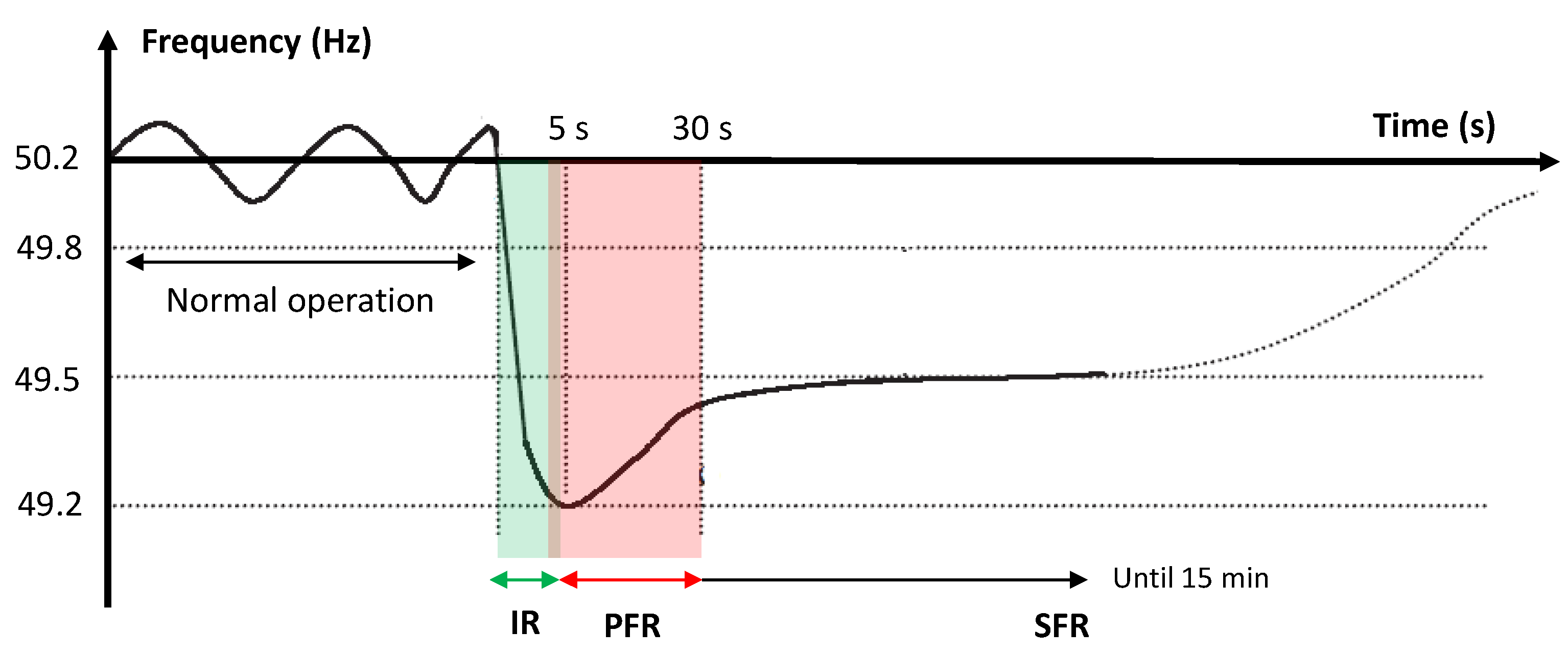
After major power imbalances, the frequency response of power systems can be roughly divided into three main phases: inertial response (IR), primary frequency response (PFR), and secondary frequency response (SFR) (Depending on the power system or transmission system operator involved, other names can be found for primary and secondary response).
Figure 1 presents the relevant time frames involved in each phase of the system frequency response when considering a generation outage.
Figure 1.
Time frames involved in the system frequency response.
Figure 1.
Time frames involved in the system frequency response.
2.1. Inertial Response
After the power imbalance, the system frequency will decrease at a rate mainly determined by the total inertia of the system [
16]: the lower the system inertia, the faster the system frequency will decrease [
17]. The average inertia constant for a power system
Hsys is determined by the combined inertia of all rotating synchronous generators connected to the system according to:
where
and
are the inertia constant and the nominal power of generator
, respectively.
Immediately after a fault, the synchronous generators are not able to produce instantaneously the required additional power to maintain power equilibrium in the system due to the time delays of the speed governors. The initial difference between the generated power and the load is covered by additional power drawn from the kinetic energy of synchronous generators. A generator can be considered to contribute to the system IR if a change in system frequency causes a change in its rotational speed and thus, its kinetic energy [
16]. This contribution leads to a speed reduction of the machines until the rate of change of frequency (d
f/d
t) becomes zero [
18]. This type of response of synchronous generators is called inertial response [
19]. This natural reaction of synchronous machines is inherently dictated by the swing equation (in per unit):
where
H is the inertia constant (in seconds), ω is the rotational speed of the generator,
Tm is the mechanical torque, and
Te is the electromagnetic torque.
Based on Equation (2), synchronous generators provide a counter response during several seconds whenever the mismatch between generation and consumption remains. Thus, any sudden change in generation is initially compensated by extraction of kinetic energy from the rotating masses of the synchronous generators. Beyond this natural response, other actions not accounted for in Equation (2) begin to affect the dynamic behavior of the power system.
2.2. Control-Dependent System Response
After a time delay of some seconds, the governors of synchronous generators begin to act upon its valves or gates, leading to an increase in the output power of the turbines. Synchronous generators will thus increase their generation until the balance between generation and consumption is restored and the system frequency has been stabilized. This second phase is called primary frequency control, and it is related to the PFR in
Figure 1. This response occurs in a time frame from 5 to 30 s, depending on the characteristics of the generation units.
To restore the frequency back to its nominal value and to release the used primary power reserves, secondary frequency control is required. Secondary frequency control (SFR in
Figure 1) consists of adjusting the power set-point of the generation units, usually controlled through an automatic generation control (AGC). Secondary power reserves are engaged in approximately 30 s after a contingency, and must be fully operational within 15 min. Once both control actions occur, the system frequency is restored to its nominal value.
3. Definition of a New Type of Frequency Response
According to the above section, the behavior of power systems during the time frame of IR is significantly related to the natural behavior of synchronous generators governed by the swing equation and has nothing to do with additional control actions. In this context, frequency support provided by inertia-less generation units in deloaded operation would not be covered by the current definitions.
One option to cover this gap could be to discuss
virtual inertial response, as is usually proposed for converter-based WTs. Nevertheless, an inertial response provided through a supplementary control action does not fit with the traditional understanding of IR. The main reason for this discrepancy is that this virtual inertial response would not be related to any “natural behavior” of PV units. In the case of converter-based WTs, this definition is acceptable because WTs have actually a natural inertial response and thus, such a control action would, in some way, only “recover” the natural response of the turbines. However, what type of IR can actually be provided by inertia-less PV units? Because no rotating parts are involved, the IR of a PV-PP should not be classified as an inertial response as such. The only way to justify such categorization would be that the control scheme reacts in the same time frame of the classical IR of conventional synchronous generators due to the fast reaction times of the power electronic converters. Nevertheless, the phenomena involved are completely different in the case of conventional synchronous generators and PV units; therefore, they should be distinguished. Distinguishing between different phenomena in power systems is essential for understanding the underlying causes of different problems to develop the appropriate design and operating procedures [
22].
To solve this situation we propose to introduce a new type of frequency response that is only valid for inertia-less generation units. We denote this type of frequency support as “Fast Frequency Response” (FFR). The definition is as follows: “FFR corresponds to the frequency response of all types of generation technologies not responding to Equation (2) immediately after major power imbalances. The FFR is determined by the additional active power injected by these generation units responding to an additional control loop. The time frame involved can last until several seconds after the contingency depending on the control parameters”.
In the remaining document, we adopt this new definition for PV units able to support frequency recovery during the first seconds after major power imbalances.
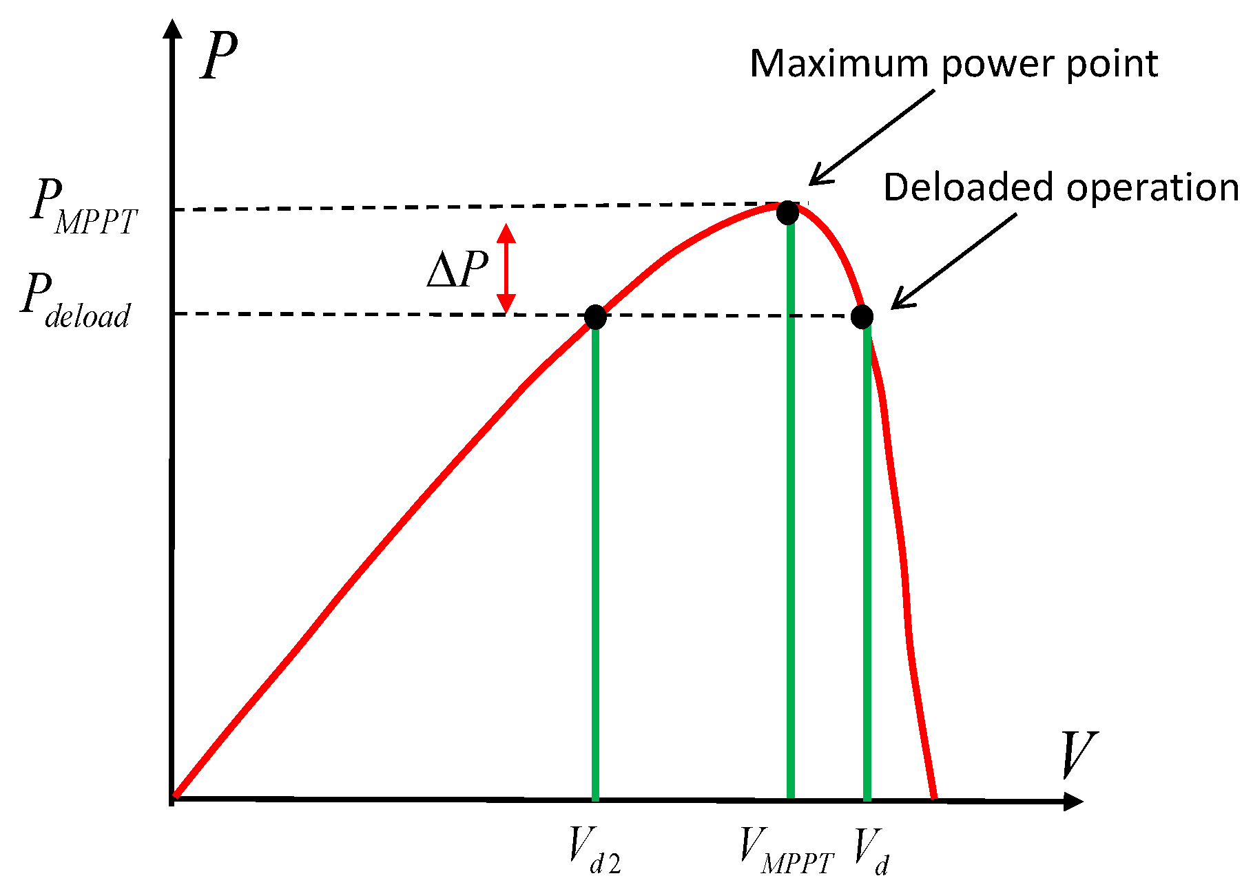
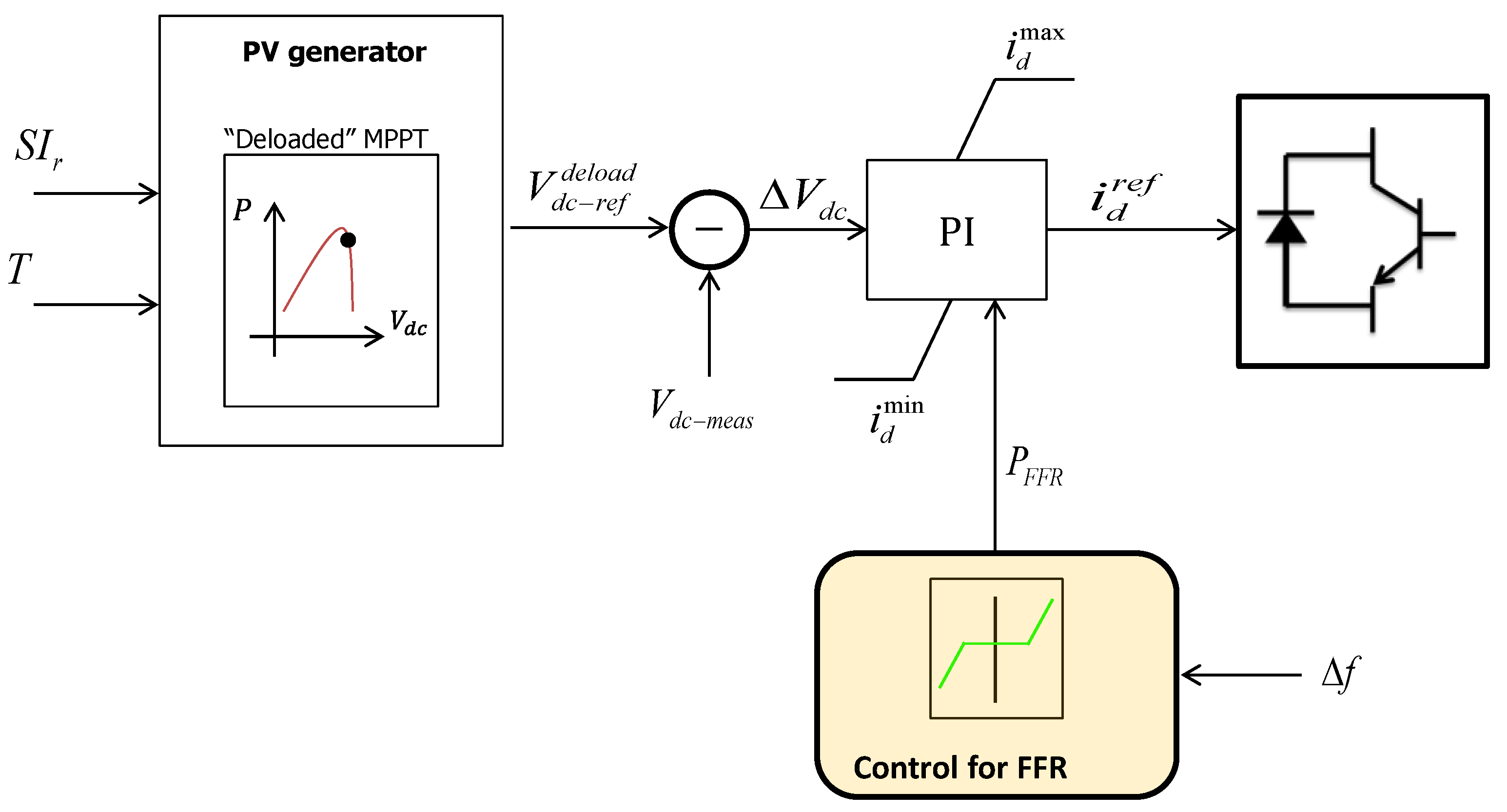
4. Control Scheme for Fast Frequency Response (FFR) in Photovoltaic Power Plants (PV-PPs)
Similar to most frequency control schemes applied in wind power plants for frequency response, instead of always extracting the maximum power from the sun, PV-PPs can be controlled to maintain power reserves for FFR by operating them below their optimal operating point (deloaded operation) [
3]. In this way, PV-PPs are able to support system frequency response similar to conventional synchronous generators by increasing the generated active power when the system frequency decreases. The deloaded operation is illustrated in
Figure 2.
Figure 2.
Deloading process in photovoltaic power plants (PV-PPs).
Figure 2.
Deloading process in photovoltaic power plants (PV-PPs).
As seen in
Figure 2, for a determined temperature and irradiance, PV units can be deloaded by operating them at reduced/increased DC voltage with respect to the optimal DC operation voltage (
VMPPT). Both alternatives result in an output power reduction Δ
P. In this work, the operation with increased DC voltage is selected.
The control strategy for FFR can be implemented by adding a supplementary control signal that allows PV units react to system frequency changes in the time frame of seconds. One control option is shown in
Figure 3 [
5,
6].
The control for FFR in PV-PPs is similar to the speed governor of conventional synchronous generators used for primary frequency control, i.e., a proportional controller based on system frequency deviation. The change in the output power is characterized by the droop characteristic R. Although the proposed control strategy is well known for primary frequency control in synchronous generators, the fast dynamic response of power electronic converters allows this control scheme to react in the time frame of the classical IR of conventional synchronous generators.
According to
Figure 3, the “PV generator” block will generate, based on the temperature (
T) and solar radiation (
SIr), a reference “deload” DC voltage (
) higher than its optimal value (this reference voltage corresponds to
Vd in
Figure 2) and the PV array will operate in deloaded mode. This reference DC voltage will be between the optimal DC voltage (
VMPPT) and
Vd in
Figure 2. This reference value is subsequently compared with its actual value (
Vdc-meas), and the error is sent to a PI controller thereafter, which generates the reference value (
) for the d component of the current that regulates the active power. The PI controller is limited by two parameters,
and
, and the variable
from the block “Control for FFR”.
Figure 3.
Control scheme for fast frequency response (FFR) in PV-PPs.
Figure 3.
Control scheme for fast frequency response (FFR) in PV-PPs.
5. Case Study
5.1. Power System under Study: Northern Interconnected System (NIS) of Chile
The electricity system in the northern part of Chile (NIS) is a small isolated 50 Hz system with a current peak load of 2200 MW. The system is characterized by a pure thermal generation mix with a total installed capacity of 4500 MW based on coal, oil and natural gas. The system load is characterized by 90% industrial load (mining industry), and the remaining 10% corresponds to residential customers.
The NIS is located in the middle of the Atacama Desert and therefore is a good example of a power system exhibiting an outstanding solar potential for PV projects. Nevertheless, important technical constraints of its conventional generation units could hamper the definitive network integration of these PV projects, mainly due to some frequency stability issues. A manual secondary regulation and conventional generators characterized by low inertia, slow reaction times, and limited ramp rates are some of the key issues to be considered. Because generators are strongly limited in their ability to provide frequency response during contingencies, under frequency load shedding schemes (UFLSS) are activated if the system frequency decreases below 49 Hz. In this way, power system stability can be sustained in the case of major power imbalances between load and generation.
Although the NIS still does not have a significant presence of PV generation, it is expected that PV generation will play an increasing role in the near future: up to April 2013, there were approximately 3 GW of approved PV projects for interconnection to the NIS, and there are still more under study [
23].
5.2. Considered PV Scenarios
The study is performed for three PV scenarios, namely S1, S2, and S3, with the total PV capacity of each scenario being 8%, 16%, and 22%, respectively, of the total installed capacity of the system at the year 2020. Concretely, the installed capacity at each scenario is 450, 950, and 1290 MW in S1, S2 and S3 respectively. The scenarios are built using the available information of future PV projects that correspond to current private initiatives. In addition, a base scenario without PV generation is also considered for comparison purposes (S0).
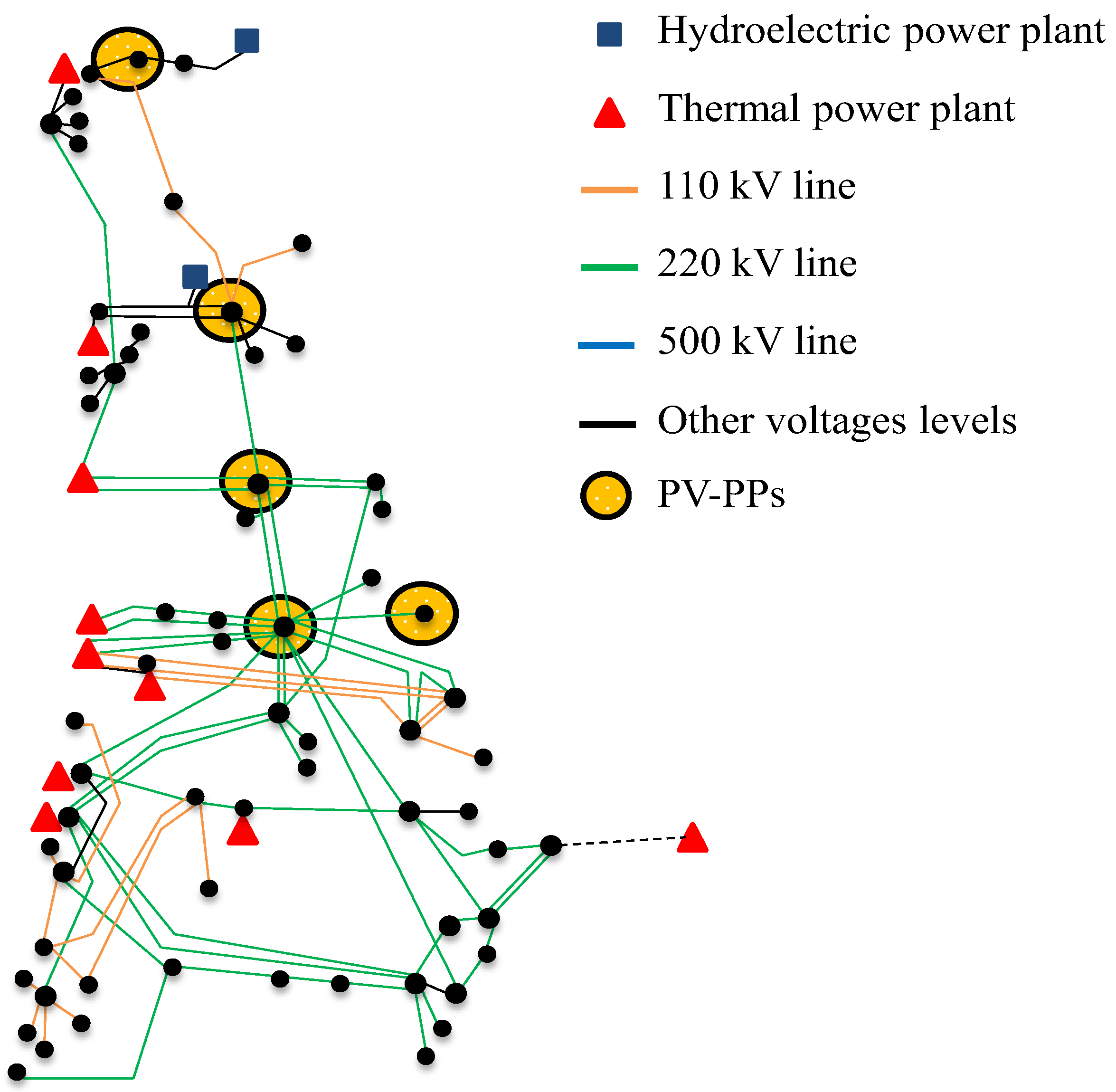
The PV-PPs are distributed in five locations throughout the system with high solar potential. To illustrate the network structure and the locations of the PV injections in the network, a simplified diagram is shown in
Figure 4.
Figure 4.
Simplified diagram of the Northern Interconnected System (NIS) of Chile.
Figure 4.
Simplified diagram of the Northern Interconnected System (NIS) of Chile.
5.3. Operating Conditions and Considered Contingencies
As usual, in a dynamic analysis of real power systems, the dynamic simulation is performed only for critical contingencies and some operating points of the system (worst case scenario). This approach is justified because the dynamic analysis of all possible contingencies and operating conditions of a real power system would lead to an intolerable amount of time and simulations.
In this work, the sudden outage of the largest online generation unit is considered to be a critical contingency from a frequency stability perspective, thus representing a worst case scenario.
Regarding the operation point, inertia problems are most likely to arise during periods of low load and high PV injections, in which case a limited number of conventional generators would be operating to support frequency response. Considering this, the selected operation point corresponds to a system demand of 2150 MW (40% of the projected peak load at year 2020).
Table 1 presents the main characteristics of each scenario, where the factor PV/Demand defines the PV penetration level for the operation point in percentage. A PV penetration level of 39% (scenario S2), indicates that 39% of system demand (corresponding to 839 MW at this particular operating point) is covered by PV generation. The average inertia constant of the system is calculated based on Equation (1).
Note that as the PV generation increases, the on-line conventional generation units in each scenario are determined based on a traditional economic dispatch exercise, considering the technical constraints of the generators, such as the minimal and the maximal power.
Table 1.
Characteristics of the Scenarios.
Table 1.
Characteristics of the Scenarios.
| Scenario | Power Injections of Conventional Generators | Power Injections of (PV-PPs) | PV Penetration Level: PV/Demand | Average Inertia Constant |
|---|
| MW | MW | % | s |
|---|
| S0 | 2219 | 0 | 0 | 4.50 |
| S1 | 1811 | 401 | 19 | 3.96 |
| S2 | 1377 | 839 | 39 | 3.41 |
| S3 | 1114 | 1137 | 53 | 3.29 |
5.4. Security Indices
To quantify the effects of PV-PPs with FFR on the dynamic performance of the power system, three security indices are considered:
Initial rate of change of frequency (ROCOF)—df/dt,
Frequency nadir—lowest frequency reached following a power imbalance, and
Steady state frequency deviation.
6. Simulation Results
A simplified 120-busbars model of the NIS at the year 2020 was implemented in the power system simulation tool DIgSILENT Power Factory [
24]. The model includes load shedding schemes and primary frequency controllers in conventional generation units. The control implemented for FFR in PV-PPs is the control presented in
Section 4, where PV arrays operate in deloaded mode.
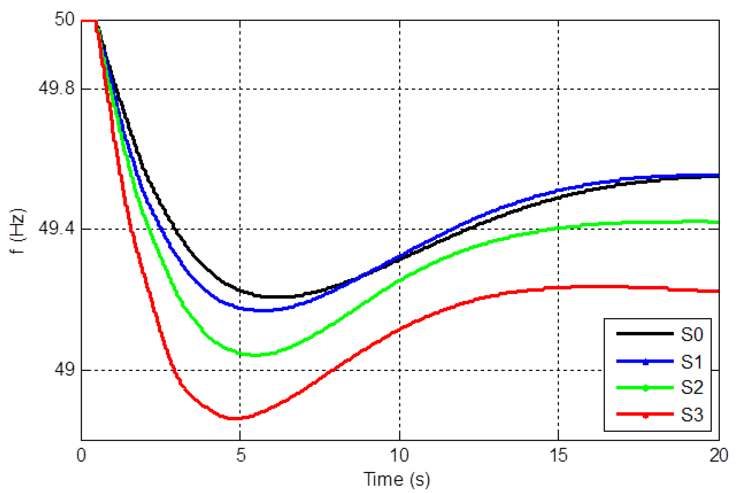
Figure 5 compares system frequency response for each scenario by the loss of the largest infeed (180 MW at
t = 0.5 s), when PV-PPs do not have FFR capability.
Table 2 summarizes the security indices in this case.
Figure 5.
Frequency response with PV-PPs without FFR capability.
Figure 5.
Frequency response with PV-PPs without FFR capability.
Table 2.
Security Indices: PV-PPs without FFR capability.
Table 2.
Security Indices: PV-PPs without FFR capability.
| Scenario | Initial rate of change of frequency (ROCOF) | Frequency Nadir | Steady State Frequency Deviation |
|---|
| Hz/s | Hz | Hz |
|---|
| S0 | −0.29 | 49.21 | 49.55 |
| S1 | −0.34 | 49.17 | 49.56 |
| S2 | −0.39 | 49.04 | 49.42 |
| S3 | −0.53 | 48.86 | 49.23 |
As expected, when the PV-PPs do not support FFR, the system performance decreases as the PV penetration level increases, confirming the detrimental effect of PV-PPs without frequency response. It can be observed that for low PV penetration levels (scenario S1, PV/Demand = 19%), no significant effects arise on the system frequency response when compared with the base scenario S0. In contrast, when the PV penetration level is approximately 50% (scenario S3), the obtained frequency nadir leads to the activation of two steps of the UFLSS (load shedding in the Chilean system begins at 49 Hz).
The reduction of system inertia due to the replacement of conventional synchronous generators by PV units is confirmed by inspection of the initial rate at which the frequency falls (ROCOF) and the initial frequency nadir: (1) the ROCOF changes from −0.29 Hz/s in the base scenario S0 to −0.53 Hz/s in scenario S3 and (2) the frequency nadir (minimum frequency) decreases from 49.21 Hz in scenario S0 to 48.86 Hz in scenario S3. The steady state frequency deviation is also deteriorated as the PV penetration level increases, reaching a steady state value of 49.23 Hz in scenario S3.
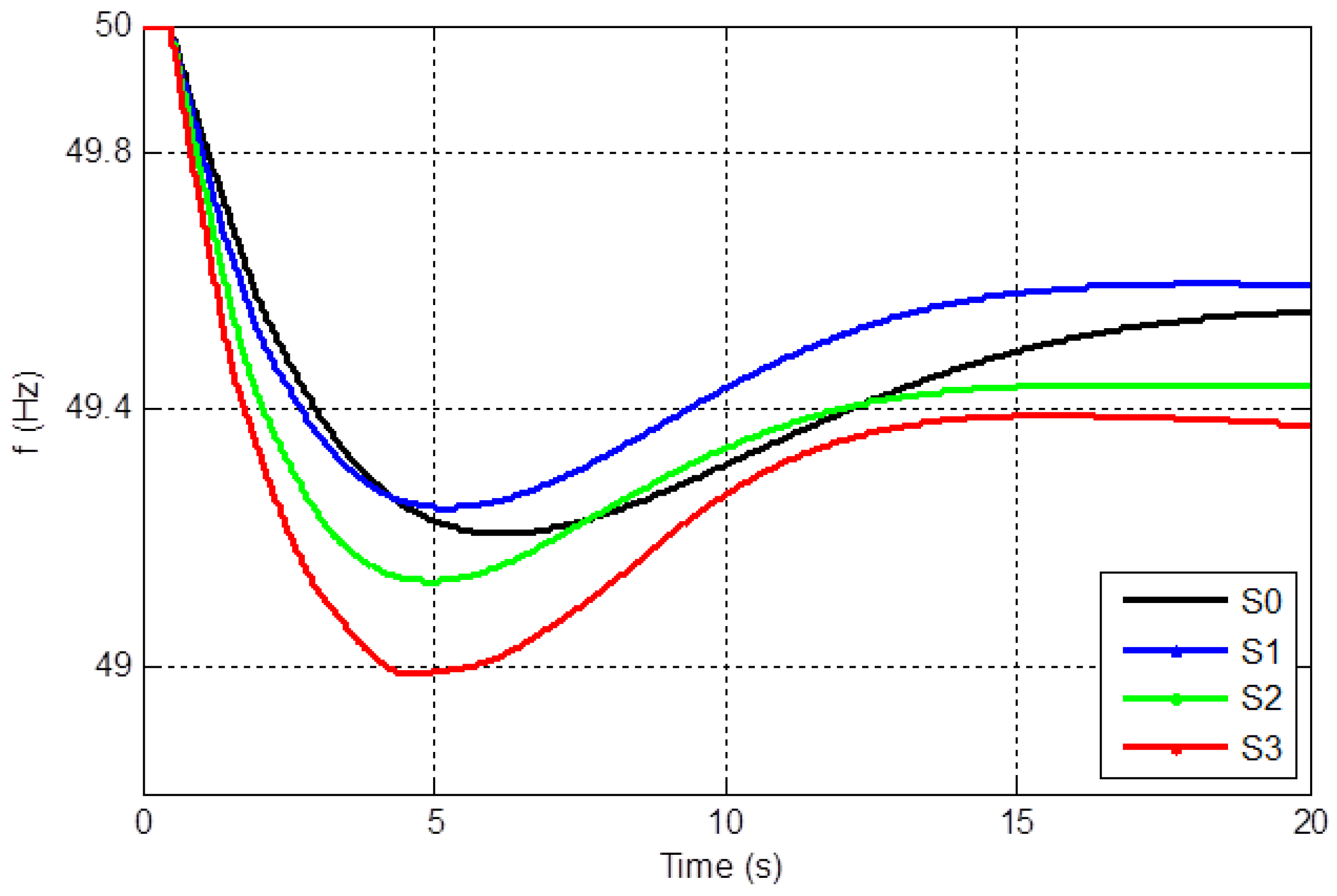
Figure 6 shows the system frequency response for each scenario when PV-PPs provide FFR with a deload margin of 3%. Simulations are made for the same contingency as before. For comparison purposes, the frequency response of scenario S0 is also presented in
Figure 6.
Table 3 summarizes the security indices in this case.
Figure 6.
Frequency response with PV-PPs providing FFR, 3% deload margin.
Figure 6.
Frequency response with PV-PPs providing FFR, 3% deload margin.
Table 3.
Security Indices: PV-PPs with FFR capability, deload margin of 3%.
Table 3.
Security Indices: PV-PPs with FFR capability, deload margin of 3%.
| Scenario | ROCOF | Frequency Nadir | Steady State Frequency Deviation |
|---|
| Hz/s | Hz | Hz |
|---|
| S0 | −0.29 | 49.21 | 49.55 |
| S1 | −0.35 | 49.25 | 49.59 |
| S2 | −0.43 | 49.13 | 49.44 |
| S3 | −0.50 | 48.99 | 49.38 |
Comparison of
Table 2 and
Table 3 indicates that the FFR capability in PV-PPs does not really affect the initial ROCOF of the system, but influences its frequency nadir (system IR) and the steady state frequency deviation. Indeed, a comparison of
Figure 5 and
Figure 6 indicates that adding FFR in PV-PPs improves the system inertial response—measured as the initial frequency nadir—in all scenarios compared to the case when no frequency response is considered. Furthermore, when the PV penetration level is 19% (scenario S1), the performance of the system frequency response even improves when comparing with the scenario without PV generation (S0). Nevertheless, this improvement is only observed for low PV penetration levels. As the PV penetration increases (scenarios S2 and S3 with PV penetration levels of 39% and 53%, respectively), the system IR is deteriorated compared to the base scenario without PV generation. As a result, it can be concluded that PV-PPs with FFR initially improve the system performance; however, as the PV penetration continues to increase, the system performance will reach a maximum level of improvement, and then begin to decrease as the PV penetration level increases further.
Although the activation of the UFLSS is not entirely avoided in scenario S3, the inclusion of FFR in PV-PPs with a deload margin of 3% at least prevents the activation of one step of the UFLSS.
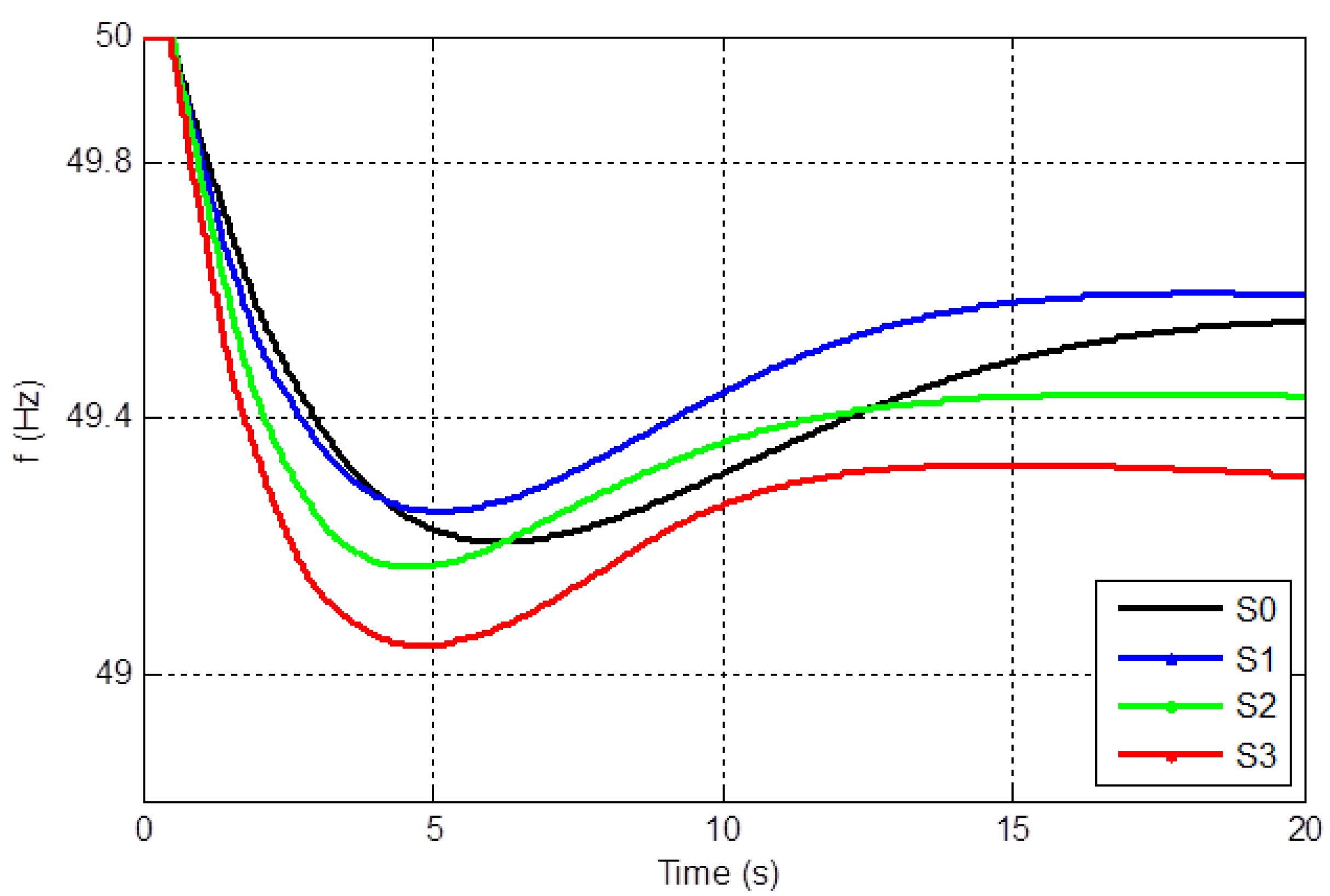
The fact that one step of the UFLSS is still activated indicates that 3% of reserve margin in PV-PPs is not sufficient in scenario S3 (PV penetration level of 53%) when the outage of the largest infeed is considered. To completely avoid the activation of UFLSS, a deload margin of 5% is now considered.
Figure 7 shows system frequency response for each scenario when PV-PPs have FFR with a deload margin of 5%.
Table 4 summarizes the security indices.
Figure 7.
Frequency response with PV-PPs providing FFR, 5% deload margin.
Figure 7.
Frequency response with PV-PPs providing FFR, 5% deload margin.
Table 4.
Security Indices: PV-PPs with FFR capability, deload margin of 5%.
Table 4.
Security Indices: PV-PPs with FFR capability, deload margin of 5%.
| Scenario | ROCOF | Frequency Nadir | Steady State Frequency Deviation |
|---|
| Hz/s | Hz | Hz |
|---|
| S0 | −0.29 | 49.21 | 49.55 |
| S1 | −0.33 | 49.26 | 49.59 |
| S2 | −0.41 | 49.17 | 49.44 |
| S3 | −0.51 | 49.05 | 49.32 |
Comparison of
Table 3 and
Table 4 indicate that for low PV penetration levels (scenario S1 with PV penetration level of 19%), the system IR is very similar to that obtained with a deload margin of 3%. Thus, an increase in the deload margin to 5% of PV units is not justified for low PV penetration levels. In contrast, in scenario S3 (with a PV penetration level of 53%), the increase in the deload margin to 5% completely avoids the activation of the UFLSS, thus making an important difference from a power system security point of view. Other deload margins above 5% were also considered in the study. Nevertheless, the obtained results do not really differ from those obtained with a deload margin of 5% because the PV power reserves are not fully deployed (only minor changes due to slight unit commitment modifications were observed). In other words, there is an “
effectiveness window” for the deload margin to use in PV units for each operating point of the system. Outside this window, no further improvements in system frequency response should be expected, even if the deload margin in PV units increases. The effectiveness window can be determined through an
ex-ante security evaluation carried out for different operating conditions of the power system. The security assessment comprises the simulation of the worst contingency that the power system can experience from a frequency viewpoint by considering different deload margins in PV-PPs. In this way, the minimum deload margin required to ensure a specific security target (for instance, to avoid the activation of UFLSS), for a particular PV penetration level can be determined. Starting from the minimum deload margin level, the maximum level can be determined as the deload margin from which no further improvements in system frequency response are obtained.
7. Discussion Regarding Frequency-Related Grid Requirements for PV-PPs
In the past, grid codes did not include any requirements for variable generation technologies regarding frequency response capability because the penetration levels were low [
25,
26]. However, a review of the latest publications and updates of international grid codes indicates that the future trend regarding FFR will be to impose stringent requirements on all types of variable generation technologies including wind power and PV generation [
27]. For example, Hydro-Quebec TransEnergie already requires wind power parks greater than 10 MW to be equipped with an inertia emulation system [
28]. Spanish and Irish grid codes have also recently recommended large wind parks to have inertial response similar to synchronous generators. Although the inertial response requirement is not compulsory at present, it is also expected to be included in futures grid codes of Spain, Ireland, New Zealand and Australia [
26].
PV-PPs are able to support system frequency recovery immediately after major power imbalances, similar to conventional generation units. Nevertheless, additional costs due to deloaded operation or the need of an ESS must be taken into account. For example, a control strategy in which PV units operate below the maximum power point would inevitably sacrifice the maximum power production of a PV-PP if an ESS is not considered. Moreover, because PV-PPs have negligible marginal costs, their power reserves are relatively expensive compared to those provided by conventional generation units; therefore, additional costs in the operation of the power system itself could also arise. Although FFR in PV-PPs will always lead to additional costs, such costs could be necessary in some power systems due to security reasons. For example, in the present work, the obtained results indicated that in an isolated power system with low inertia and limited frequency control capacities, for PV penetration levels of approximately 50%, deloaded PV-PPs with FFR capability may be more valuable to the system than maximizing the solar energy itself.
Nevertheless, from a grid code perspective, there are still several questions regarding the applicability and pertinence of FFR requirements. For example, when should it be required that PV-PPs provide FFR? A general conclusion of several recent studies addressing power systems with variable generation technologies is the need of dynamic reserve requirements depending on the system operating conditions. Transmission system operators should use the information available to establish those operating conditions involving high or low levels of risk, and then schedule operating reserves accordingly [
29]. Because keeping the same requirements for PV units all times of the day and all days of the year would make no sense from any point of view, a reasonable criterion is to require FFR only at some hours of the year, based on a specific security criterion, for example, based on the PV penetration level. The idea behind this approach would be to request FFR capability only during periods of low load and high PV injections, in which case a limited number of conventional generators would be operating to support the system frequency response. In this case, an ex-ante assessment would be necessary to establish hazardous PV penetration levels from a power system security perspective. Another criterion could be to require a minimum level of system inertia at each hour of the year,
i.e., an inertia target.
Another important question when discussing the frequency requirements for PV-PPs involves the optimal reserve level to be kept. In this context, the present investigation indicated the existence of an “effectiveness window” for the deload margin to use in PV units. Outside of this window, no further improvements in the system frequency response can be observed for a specific operating condition, even if the deload margin in PV units increases. The optimal deload margin level to be maintained in PV units is highly related to the PV penetration level as well as the characteristics of the online conventional generation units, and therefore, should be different for each hour during the year.
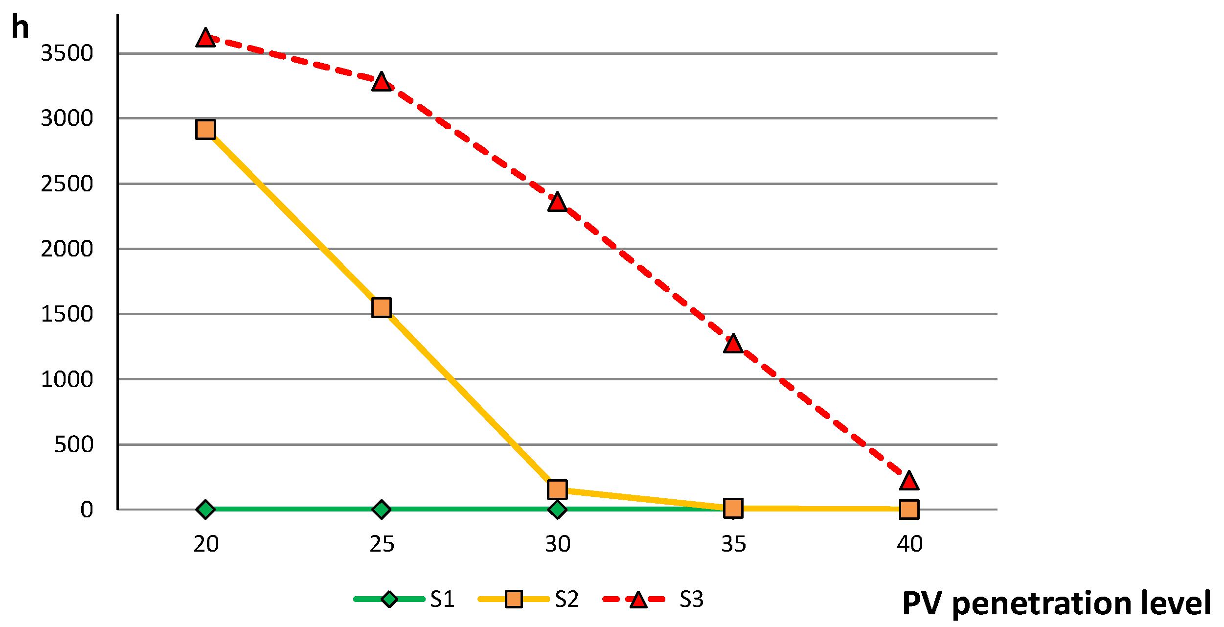
To visualize the impact of FFR capability in PV-PPs from an investor point of view,
Figure 8 shows, for the Chilean case, the hours during the year in which PV-PPs would be in deloaded operation when considering the PV penetration level as security criteria. For instance, the figure shows that requiring FFR capability at all those hours during the year with PV penetration levels above 35%—meaning that FFR capability will be required only at all those hours in which PV generation covers more than 35% of system demand—would result in PV units working in deloaded operation only 9 h during the year in scenario S2 and 1250 h in scenario S3. In the case of scenario S1, deloaded operation would never be required. If a penetration level of 35% is considered as a security criteria, the total annual PV energy loss during the year would be approximately 1% of the annual available PV energy in the case of scenario S3 for a deload margin of 3%. If the deload margin is 5%, the total annual PV energy loss would be approximately 2%.
Figure 8.
Hours during the year with PV-PPs in deloaded operation.
Figure 8.
Hours during the year with PV-PPs in deloaded operation.
8. Conclusions
This paper addressed the key aspects regarding large scale PV-PPs with frequency response capability and its applicability and pertinence in real power systems. First, we proposed a new terminology to denote the frequency support capability of inertia-less generation units during the first seconds after major power imbalances. We denoted this type of support as fast frequency response (FFR). Because no rotating parts following the swing equation are involved, we claimed that such capability in PV units cannot be classified as an inertial response.
The positive effects of deloaded PV-PPs with FFR capability on the frequency response of power systems were also examined. The investigation was performed for the isolated power system of Northern Chile. The results of the dynamic simulations indicated that the system frequency response is deteriorated as the PV penetration level increases, confirming the negative effects of PV units without FFR capability. Nevertheless, for PV penetration levels below 20%, the effects were not significant compared with the base scenario without PV generation. For penetration levels of approximately 50% or greater, the frequency response was worsened to such an extent that under frequency load shedding schemes (UFLSS) were activated.
The implementation of FFR in PV-PPs through deloaded operation improved the system inertial response in all scenarios compared to the case without FFR capability. Moreover, for low levels of PV generation, FFR in PV units even improved the system frequency response compared to the base scenario without PV generation. Nevertheless, as the PV penetration level increased, the system frequency response reached a maximum point of improvement to finally begin to decrease as the PV penetration further increases. PV-PPs with FFR capability can also avoid the activation of UFLSS in the case of major disturbances. For the system under study, a deload margin of 5% was required to avoid the activation of UFLSS completely in the case of a PV penetration level of 50%. Thus, in an isolated power system with low inertia and limited frequency control capacities, for high PV penetration levels, deloaded PV-PPs with FFR capability was found to be more valuable to the system than maximizing the solar energy itself. Nevertheless, an “effectiveness window” for the amount of deload margin to use was determined. Outside this window, no further improvements in the system frequency response were observed, even if the deload margin increased.
Finally, a discussion regarding the applicability and pertinence of frequency-related grid requirements for PV-PPs in real power systems was also presented.


