Article

Corner Separation Control by Boundary Layer Suction Applied to a Highly Loaded Axial Compressor Cascade

1
National Key Laboratory of Science and Technology on Aero-Engine Aero-Thermodynamics, School of Energy and Power Engineering, Beihang University, Xueyuan Road 37, Haidian District, Beijing 100191, China
2
Collaborative Innovation Center of Advanced Aero-Engines, Xueyuan Road 37, Haidian District, Beijing 100191, China
*
Author to whom correspondence should be addressed.
Energies 2014, 7(12), 7994-8007; https://doi.org/10.3390/en7127994
Submission received: 18 October 2014 / Revised: 12 November 2014 / Accepted: 14 November 2014 / Published: 27 November 2014

Abstract

:
Control of corner separation has attracted much interest due to its improvement of performance and energy utilization in turbomachinery. Numerical studies have been performed under both design and off-design flow conditions to investigate the effects of boundary layer suction (BLS) on corner separation in a highly loaded compressor cascade. Two new BLS slot configurations are proposed and a total of five suction slot configurations were studied and compared. Averaged static pressure rise, exit loss coefficient, passage blockage and flow turning angle have been given and compared systematically over a range of operation incidence angles. Distributions of significant loss removal, blade loading, exit deviation and total pressure loss at 3 degree and 7 degree incidence have also been studied. Under the same suction mass flows of 0.7% of the inlet mass flows, the pitchwise suction slot on the endwall shows a better optimal performance over the whole operation incidence among single suction slots. By using of the new proposed compound slot configuration with one spanwise slot on the blade suction side and one pitchwise slot on the endwall, the maximum reduction of total pressure loss at 7 degree incidence can be 39.4%.

1. Introduction

Corner separation, which has been identified as an inherent flow feature of the corner formed by the blade suction surface and the endwall, is a high loss structure in axial compressors [1]. It has a great impact on the total pressure ratio, loading, efficiency and operating range of aero-engines, thus restricting the development of high performing ones. Also called corner stall, it is typically a three dimensional phenomenon whose main characteristic is the reverse flow on both the endwall and the suction surface in the compressor. If the reverse flow increases to some extent this may lead to serious consequences, such as passage blockage, a reduction in the static pressure rise, a considerable total pressure loss and reduction in compressor efficiency, which can seriously deteriorate compressor performance and eventually causes stalls and surges, especially for a highly loaded compressor. Hence, alleviating and migrating corner separation is a key method to enhance compressor efficiency and stability [2].
In order to reduce the corner separation, active flow control is regarded as a potential method to improve the pressure ratio and the compressor efficiency, thus increasing the fuel economy of aero-engines. Boundary layer suction (BLS) has been applied to theoretical and experimental research on axial compressors since in the middle of 20th century [3,4]. In 1997 the concept of an aspiration compressor was put forward by Kerrebrock et al. [5], who pointed out that BLS on the suction surfaces of the blade could increase the flow turning angle in a transonic compressor. They have since done much more research [6,7,8,9] on aspirated compressors and validated the concept of BLS on compressors and fan stages. Qiang et al. [10] studied BLS on a single-stage, low-speed axial compressor based on the concept of an aspirated compressor and they found the approach is effective and the 3D separation can be controlled by the suction.
Recently, more research has been conducted on secondary flow suppression in the compressor cascade by BLS. Song and Chen et al. [11,12] studied various positions and suction flow rates on blades and they found that a suction slot located at 0.7 axial chord contributes to the largest loss reduction and they combined two suction slots on the suction surface to further reduce the total pressure of the cascade. Chen and Liesner et al. [13,14] studied the effect of BLS location on the endwall on high Mach number compressor cascades and with experimental validation they achieved a 15.2% reduction of total pressure loss.
Guo et al. [15,16,17] carried out experimental research both on the blade suction surface and on the endwall and found that the compound suction scheme works better with high suction flow rates compared with a single slot. A pitchwise endwall suction slot drilled at 13% chord upstream of the cascade was also investigated. Guo et al. found that the inlet BLS schemes could be more effective under large suction flow rates. Zhang et al. [18] and Ding et al. [19] conducted numerical and experimental studies on BLS holes on the suction surface of the blade and on the endwall. The total pressure loss decreased by 27% with a compound BLS layout. Cao et al. [20] evaluated three suction slot schemes on the blade suction surface by combining one suction slot with one spanwise slot on the blade suction side and one streamwise slot on the endwall. With combined suction, the separation along the blade surface and the suction surface are both completely removed.
Gbadebo et al. [21] compared the effect of suction slots located on the suction surface of the blade and endwall, respectively, by numerical and experimental research on a low-speed highly-loaded compressor cascade. The study found that a suction slot on the suction surface of the blade could reorganize the boundary layer near the blade suction surface but hardly eliminate the separation at the blade trailing edge. However, endwall suctions could eliminate corner separation at the trailing edge of the blade with suction mass flow of 0.7% of the inlet mass flows at 0 degree incidence. The study just considered two incidences, ‒7 degree and 0 degree incidence, so the effect of BLS over the whole operating range was not given and discussed.
The previous works were mainly focused on a single flow condition with suction slot configurations using BLS. In this paper, numerical studies of corner separation control by BLS have been done on a highly loaded axial compressor cascade under both design and off-design flow conditions. Two new BLS slot configurations have been proposed and five BLS slot configurations have been compared. In order to achieve a more effective slot configuration and better reveal the flow mechanism behind, the results, detailed comparisons have been done focusing on the effects of the BLS slot configurations on the cascade performance and the 3D flow field.

2. Computational Procedure

2.1. Cascade Description

A linear Prescribed Velocity Distribution (PVD) highly loaded axial compressor cascade [21] with and without BLS is studied by numerical simulation. Table 1 shows the main geometric parameters of the cascade. The inlet Mach number is 0.07, corresponding to a chord Reynolds number Rec = 2.3 × 10⁵.
Table 1. The main geometric parameters of the cascade.
ParameterMagnitude
Chord0.1515 m
Aspect ratio1.32
Solidity1.082
Camber angle42°
Stagger angle14.7°
Blade span0.20 m
Inlet metal angle41°

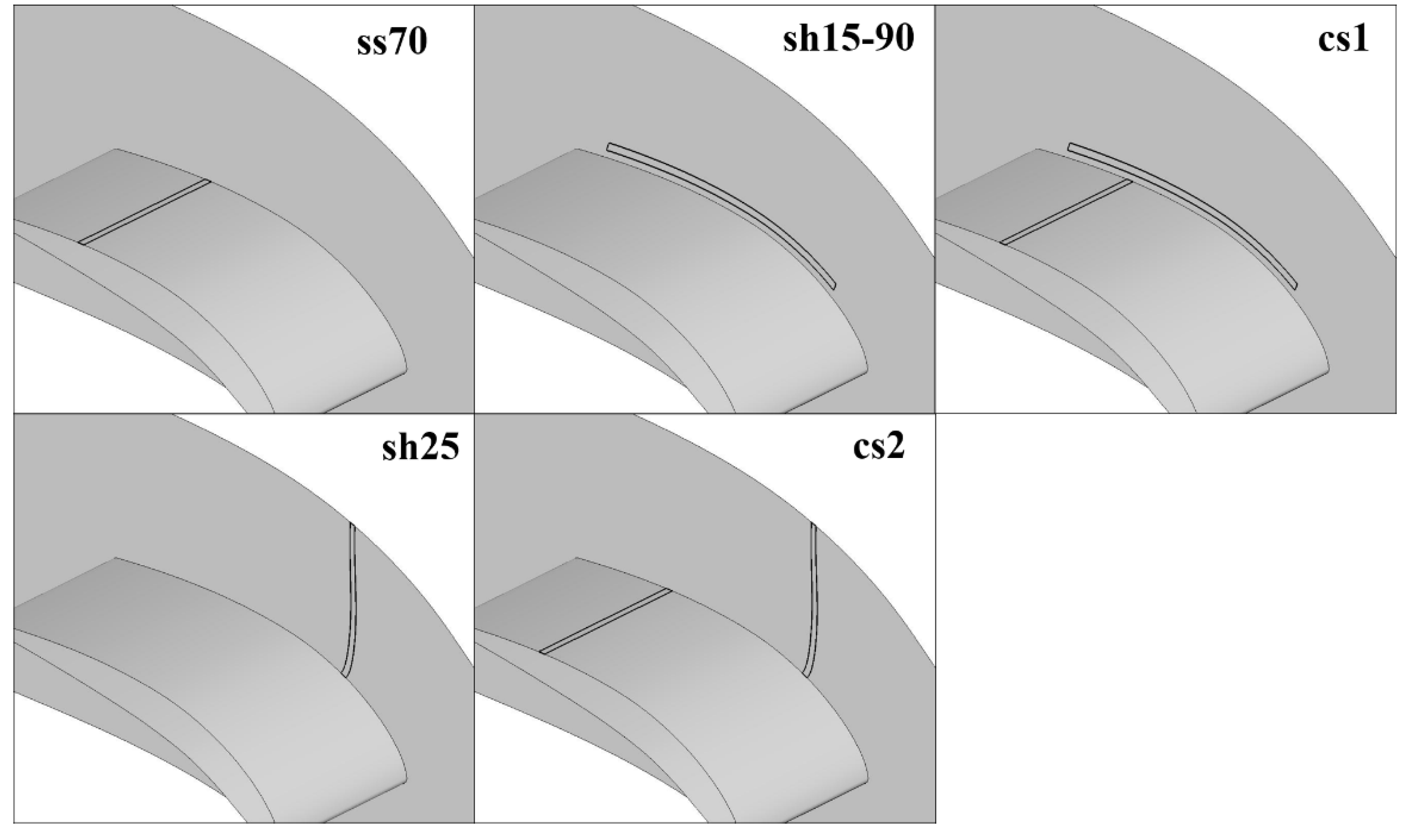
2.2. Slot Arrangements

In this paper, taking previous work as reference, a total of five suction slot configurations were considered, as shown in Figure 1. Ss70 is centered at about 70% axial chord and sh15-90 runs from 15% to 90% axial chord along the suction surface of the whole span. The third one, referred as cs1 is the combination of ss70 and sh15-90. These three slot configurations have already been put forward and investigated by other scholars. This paper explores two new slot configurations to control corner separation and improve cascade performance. The first one is sh25, which is centered pitchwise at 25% axial chord on the endwall and extends to half pitch. The second one is the combination of ss70 and sh25 which is named cs2. The suction is modeled as a boundary condition. A mass flow rate of 0.7% of the inlet mass flow rate was given for the single cases and 0.35% of the inlet mass flow rate for each compound suction slot so that the total suction flow rate is the same for these five configurations.
Figure 1. Suction slot arrangements.
Energies 07 07994 g001

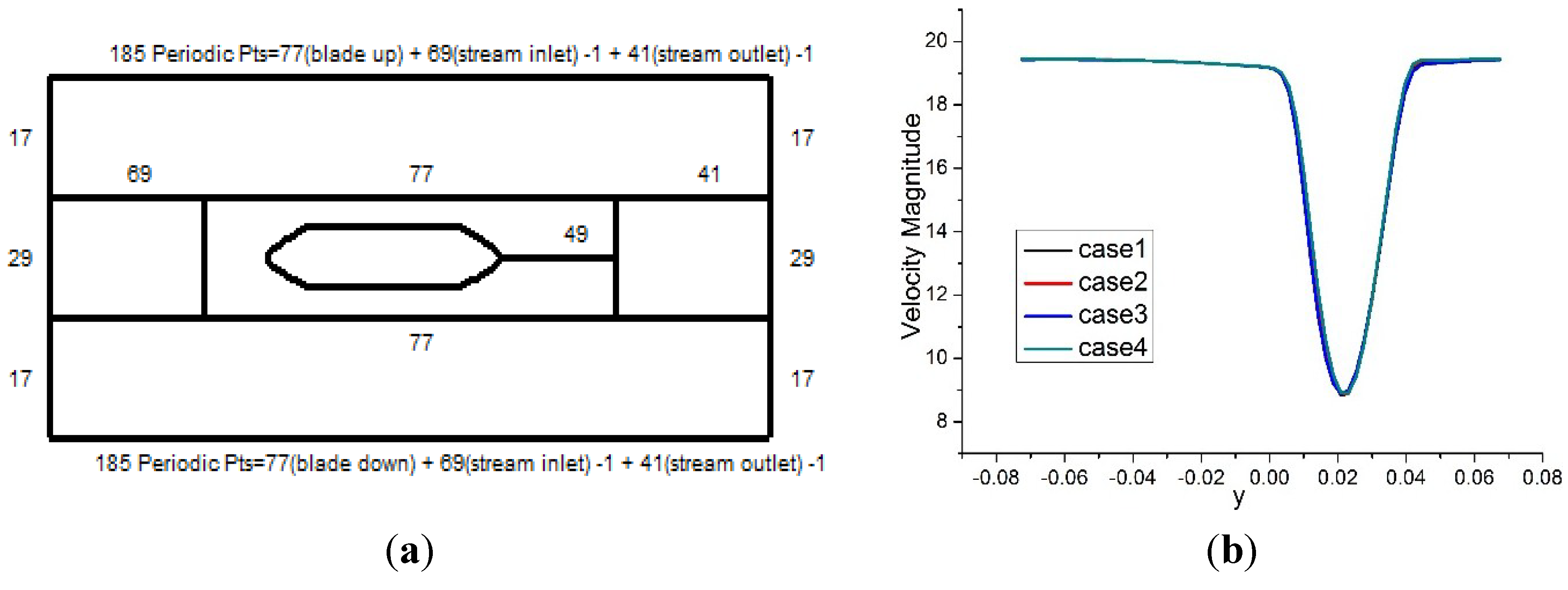
2.3. Numerical Simulation Methods

The flow in the cascade is assumed spanwise symmetric and only half of the cascade blade span is modelled in the simulation. The computation domain extends 1.5 chords upstream from the leading edge and 1 chord downstream from the trailing edge of the blade. A multi-block strategy, O4H type grid as shown in Figure 2a, was used to ensure the grid quality and make the grid fully matched. A series of grids has been generated with different grid densities and distributions to check the grid independence of the solution. Here the results from four different grids are presented in Figure 2b. The total grid numbere for Case1, Case2, Case3 and Case4 are 944,800, 1,140,800, 1,398,304 and 1,134,400, respectively. Compared with Case1, Case2, Case3 and Case4, increase the grid number in the circumferential, spanwise and streamwise directions, respectively. It can be seen that the results of Case1 should be grid independent and thus grid Case1 was chosen for the final simulations. The grid distribution near the blade hub is shown in Figure 2a. In the spanwise direction, there are 51 grid points. It is well known that the grid resolution should be high enough in the blade boundary layer, hence the distance between the first grid line and the solid wall was set to y+ ≈ 1 in the computation, which satisfies the requirement of the turbulence model used in this paper.
Profiles of velocity and absolute flow angles were used to specify inlet boundary and static pressure was given at the outlet boundary, which were set according to the experimental data. The inflow turbulence intensity was assumed at 1.5% of the velocity and the turbulent viscosity ratio was set as 50. Adiabatic and nonslip conditions were imposed over all walls.
A steady and fully turbulent flow was simulated using FLUENT based on the Reynolds-averaged Navier-Stokes (RANS) equations. For RANS calculation, the turbulence model is one of the key elements and a weakness in CFD for engineering [22]. It has been shown in our previous work that the Reynolds Stress Model (RSM) is the most suitable turbulence model for the complex 3D separations in the cascade [23] and it was thus employed in this study. The pressure-velocity coupling was performed using the SIMPLE algorithm. Second-order spatial interpolation was used for the convection terms and a second order central difference scheme was use for the diffusion terms.
Figure 2. (a) Grid topology and point distribution for Case1; (b) Velocity distribution at 10% spanwise at the outlet section.
Energies 07 07994 g002

2.4. Definitions of Flow Field Parameters

The outlet section is located at 50% chord downstream of the trailing edge which corresponds to the experiment. The definitions of the exit total pressure loss, static pressure coefficient and flow turning angle are:
Y p = P t 1 P t 2 P t 1 p s 1
C P = p s 2 p s 1 P t 1 p s 1
Δ β = β 2 β 1
Quantification of the passage endwall blockage employed in this paper is defined as [24]:
A b = ( 1 ρ u m ρ e U e ) d A
B = A b A e x
where ρ is the local density; um is thevvelocity component normal to A; A is the azimuthal cross-section; ρe and U e are the edge density and velocity of the defect region; Aex is the area of the test plane of the blade passage.
Gbadebo [21] recommended the concept of relative displacement thickness to estimate the thickness of the 3D separated layer perpendicular to the suction surface at the blade trailing edge. This can be used to judge the extent of the removal of the 3D separation by slot treatment. The relative displacement thickness can be normalized as:
{ δ * ( r ) δ m i d * } / c
where δ mid * is the relative displacement thickness at midspan. The displacement thickness is obtained at each radial location as:
δ * ( r ) = 0 δ [ 1 ρ v ( r , s ) ρ f s V f s ] d y
where y is the pitchwise distance from the suction surface; V is the flow velocity magnitude in the cascade plane; and the subscript fs denotes local free-stream conditions.

3. Results and Discussion

Computational results are presented in this section. First, the reliability of the computational tools is validated and then the effects of the various configurations of BLS on the corner separation are illustrated. Finally, BLS combinations are discussed.

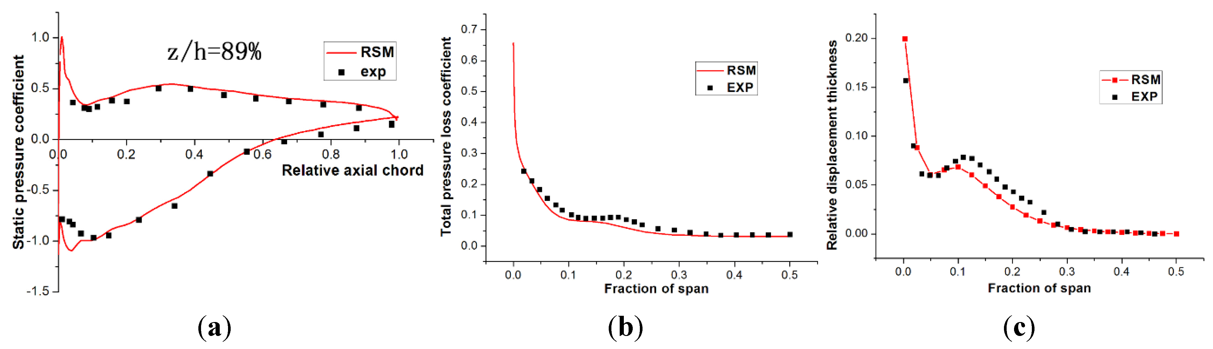
3.1. Validation of Computational Results

In order to guarantee the accuracy and reliability of the computational results, some comparisons of simulation and experimental results [25] were made. The static pressure coefficient at 89% span of the blade and the mass averaged total pressure loss coefficient at the exit of the cascade are shown in Figure 3a,b. The comparisons show that a good agreement is achieved between simulation and experimental results.
Figure 3. (a) Static pressure distribution; (b) total pressure loss coefficient; (c) relative displacement thickness.
Energies 07 07994 g003
Figure 3c shows the comparison of the normalized displacement thickness between simulation and experiment on the blade suction surface. Over the range of 10% to 25% span, the calculated result is a bit lower, but the overall trend fits well with the experimental data. This is possibly due to the assumption of a boundary layer flow state in the numerical simulations, whereas a laminar boundary layer undergoing transition is likely to have been present in the experiment, due to the local flow acceleration over the blade suction side. Therefore, from the results of Figure 3 we can conclude that the computational model and the numerical methods selected in this paper are appropriate for analyzing the aerodynamic performance of the highly load cascade.

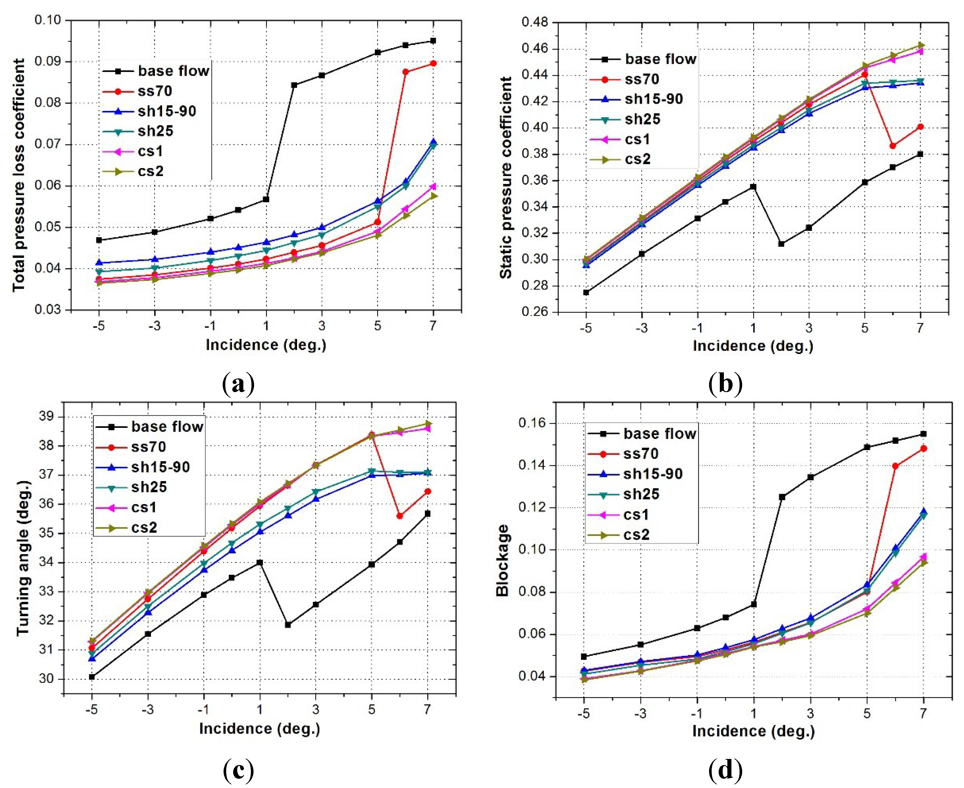
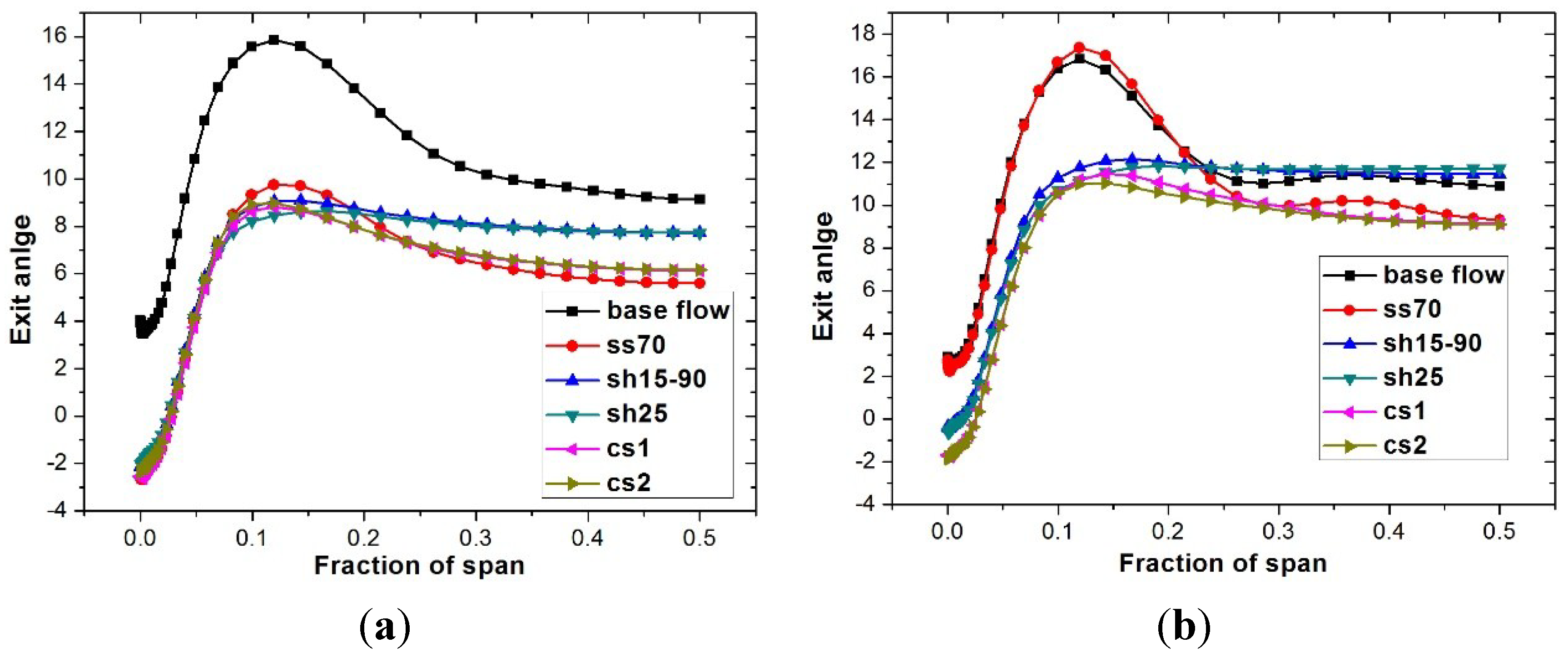
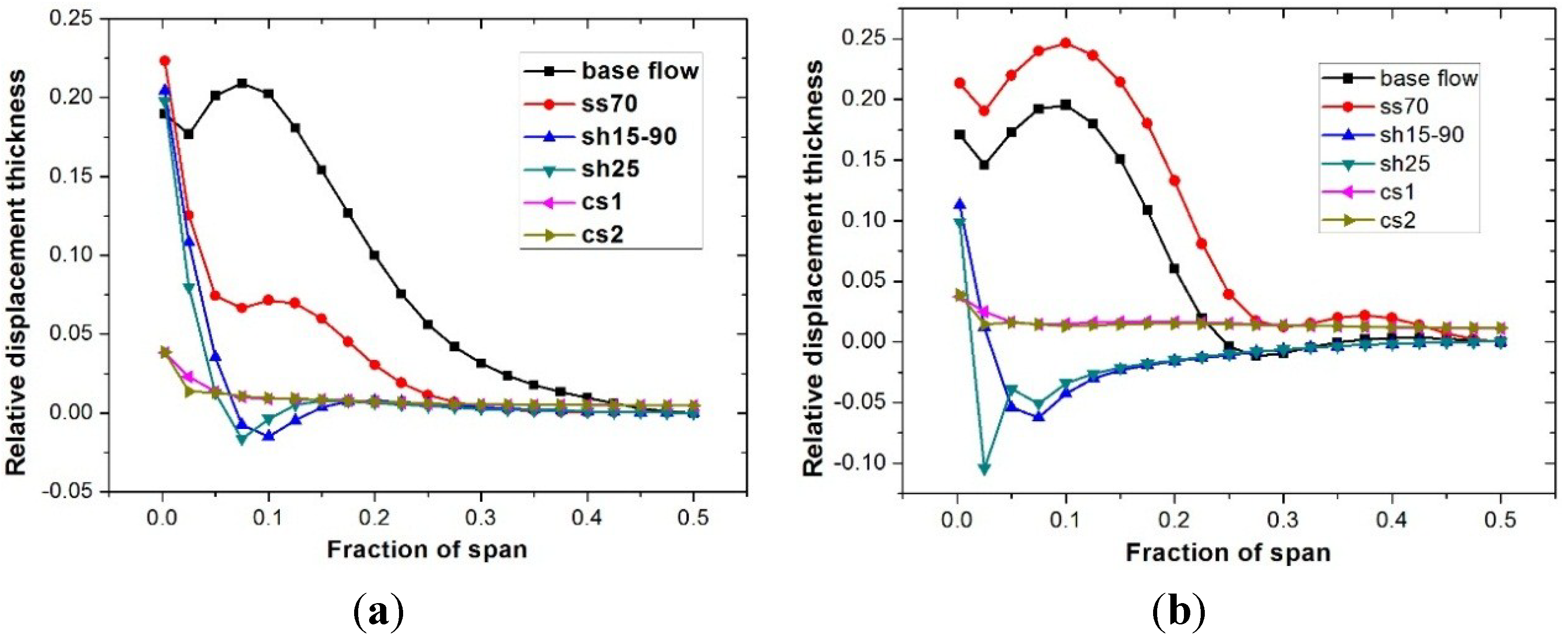
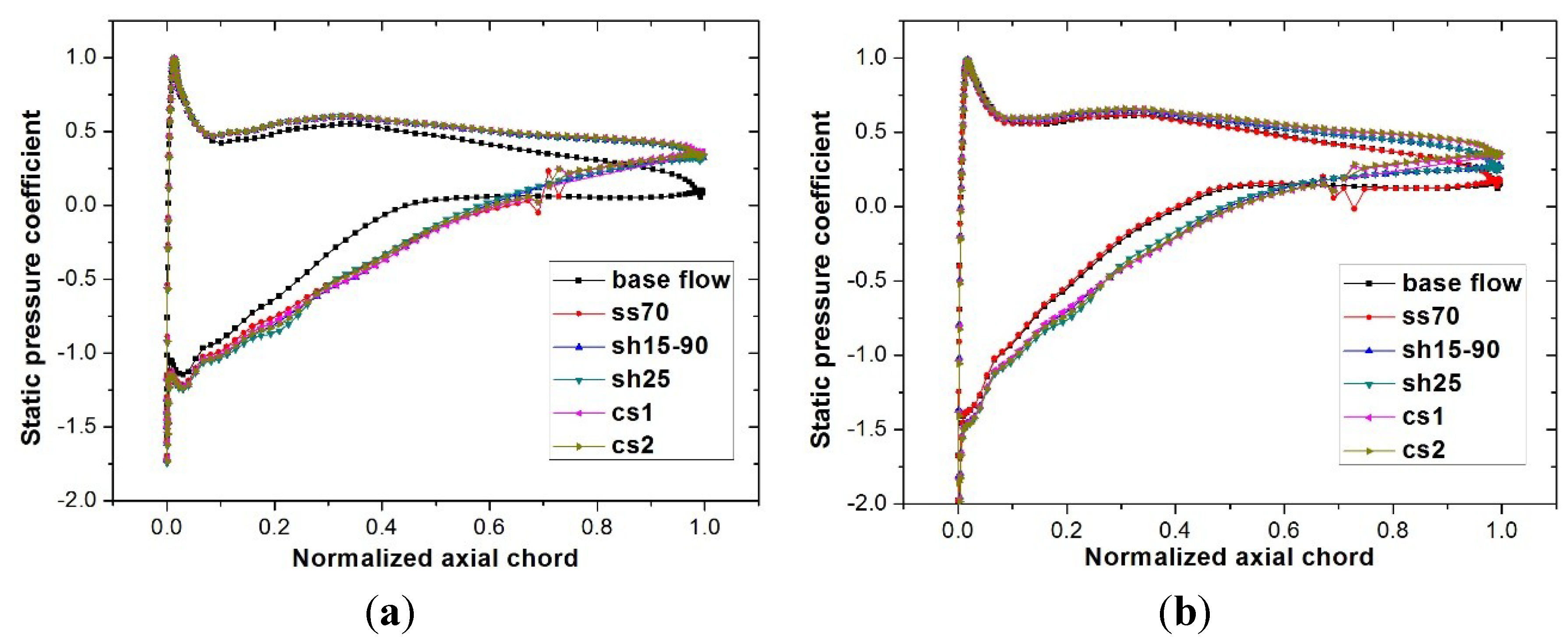
3.2. Effects of BLS Slot Configurations on Cascade Performance

The effects of the five suction slot configurations on the 3D separation and the cascade performance are discussed in this section. Figure 4 shows the aerodynamic performance of the cascade with the five suction slot configurations mentioned above.
Figure 4. Influence of different suction slot locations on cascade performance: (a) average total pressure loss coefficient; (b) static pressure coefficient; (c) flow turning angle; (d) passage blockage.
Energies 07 07994 g004
The figure shows that suction on the blade suction side or on the endwall can reduce the passage total pressure loss and improve the positive incidence range of the cascade. The total flow blockage in the passage is a useful indicator to estimate the compressor flow capacity. The blockage generally refers to the reduction in the effective passage flow area due to local velocity defects, in analogy to the displacement thickness effect associated with a boundary layer [26]. The blockage is quite small at small incidence conditions. Then the blockage coefficient increases rapidly above 3 degree incidence because of the growth of the corner separation, as shown in Figure 5.
Figure 5. Total pressure loss coefficient at the outlet section (a) i = 3 degree; (b) i = 7 degree.
Energies 07 07994 g005
In these comparisons, the ss70 suction slot that lies on the blade suction surface and within the separation region shows a better improvement in cascade performance under small incidences but loses its effect when the incidence increases to 6 degree incidence at the given mass flow rate. Suctions on the endwall can reduce the losses and improve cascade flow capacity over a wider incidence angle compared with suction on the blade at the same suction flow rate. The main trends of the two endwall suctions are similar, but the pitchwise suction provides a little more benefit than the endwall suction along blade suction surface. The two compound suction configurations show the highest loss reduction benefits, especially for the positive incidence conditions.
The low turning kinetic energy flow in a compressor passage comprises the boundary layer along the passage walls and vortex structures, such as the corner vortex or the passage vortex. In order to know the effect mechanism of these suction configurations on the low turning energy flow in the passage, local flow structure and more quantitative comparisons have been discussed.
The contours of total pressure loss at the outlet section at 3 degree and 7 degree incidence are presented in Figure 5a,b. As shown in Figure 5a, all configurations in which BLS is used display a significant effect in terms of BL reducing the loss. The reduction in the average total pressure loss was found to be about 47.7%, 42.4% and 44.3% for the ss70, sh15-90, and the sh25 configurations, respectively, relative to the base flow at 3 degree incidence. The core loss for ss70 is about 0.45, which is higher than with the endwall suction, but it shows a better average performance for its impact on the whole blade span. The possible reason for ss70 at 7 degree incidence displaying about the same base flow is that the mass flow provided in this paper is too small to suck off the low energy fluid. The loss core caused by the corner separation is eliminated by the two endwall BLSs which on the other hand have little effect on the midspan.
Figure 6 shows the spanwise distribution of the flow angle at the outlet section at 3 degree and 7 degree incidence. This clearly shows a reduced positive exit angle peak when suction is applied to remove the corner separation. It can be noted at 3 degree incidence that the reduction in peak positive exit angle for the two endwall suction configurations can extend to the midspan, although the reduction is inferior to the ss70 one. Because of the failure to remove the corner separation, the exit angle maximum below 20% span for ss70 at 7 degree incidence remains almost the same as the base flow as shown in Figure 6b. The compound BLSs, cs1 and cs2, show optimal reductions in the flow under-turning across the whole blade span. This means flow out of the cascade to the next stage is more uniform spanwise above 5% span and stage matching is improved.
Figure 6. Spanwise distribution of flow angle at the outlet section: (a) i = 3 degree; (b) i = 7 degree.
Energies 07 07994 g006
Figure 7 shows the relative displacement thickness at the outlet section. All the suction slot configurations are able to reduce the thickness of the corner separation when compared to the base flow case. As shown in Figure 7a, the thickness decreases with ss70, but below 25% span a corner separation still exists, while the entire thickness of the corner separation is virtually removed with the two endwall suction configurations. The thickness near the endwall is smaller than the boundary layer developed on the blade surface at midspan.
Figure 7. Spanwise distribution of relative displacement thickness at the outlet section (a) i = 3 degree; (b) i = 7 degree.
Energies 07 07994 g007
It can be noted that the thickness for ss70 at 7 degree incidence seems larger than the base flow case; the reason for this is the failure to remove the corner separation which can be inferred from Figure 6b. The relative displacement thickness for the compound suction slot configuration remains almost 0 across the whole span. The compound slot configurations can remove the low energy fluid both in the corner separation and the whole span, which is consistent with Figure 4 and the compound suction slot configurations showing a better overall performance compared to the single configurations.
Figure 8 shows the static pressure coefficient at 95% blade span. Compared with the base flow case, the removal of low energy fluid from the boundary layer leads to an increase in the blade loading. At 3 degree incidence, the five slot configurations all increase the blade loading and inhibit separation on the blade suction surface. The blade loading is also increased by BLS except for ss70 at 7 degree incidence.
Figure 8. Static pressure coefficient at 95% blade span (a) i = 3 degree; (b) i = 7 degree.
Energies 07 07994 g008
Limiting streamlines, as shown in Figure 9, can give a visualized flow condition on the endwall. It can be seen that the flow pattern on the endwall has been significantly improved under BLS. For the base flow, the streamlines deviate from the axial direction because of the large separation at the blade trailing edge. But for ss70, due to the fact the suction slot is lying within the separated flow region, the interaction and mixing between the suction flow and corner separation may be larger than with compound suction slots.
Figure 9. Limiting streamline on the endwall, i = 3 degree.
Energies 07 07994 g009
Sh15-90, which has been investigated by Gbadebo [21], is able to capture the dividing streamline and also suck off the bulk of the drifted endwall boundary layer from the suction surface. The thick solid line in Figure 9 presents the curvature of the streamline for each configuration, which also means the relative strength of the secondary flow from pressure side to suction side near the endwall. It can be seen that the secondary flow for sh15-90 is a little stronger than for sh25, though the bulk of the drifted endwall boundary layer is sucked off in the both slot configurations. This is the main flow mechanism why sh25 gives slightly better incidence characteristics compared with sh15-90.

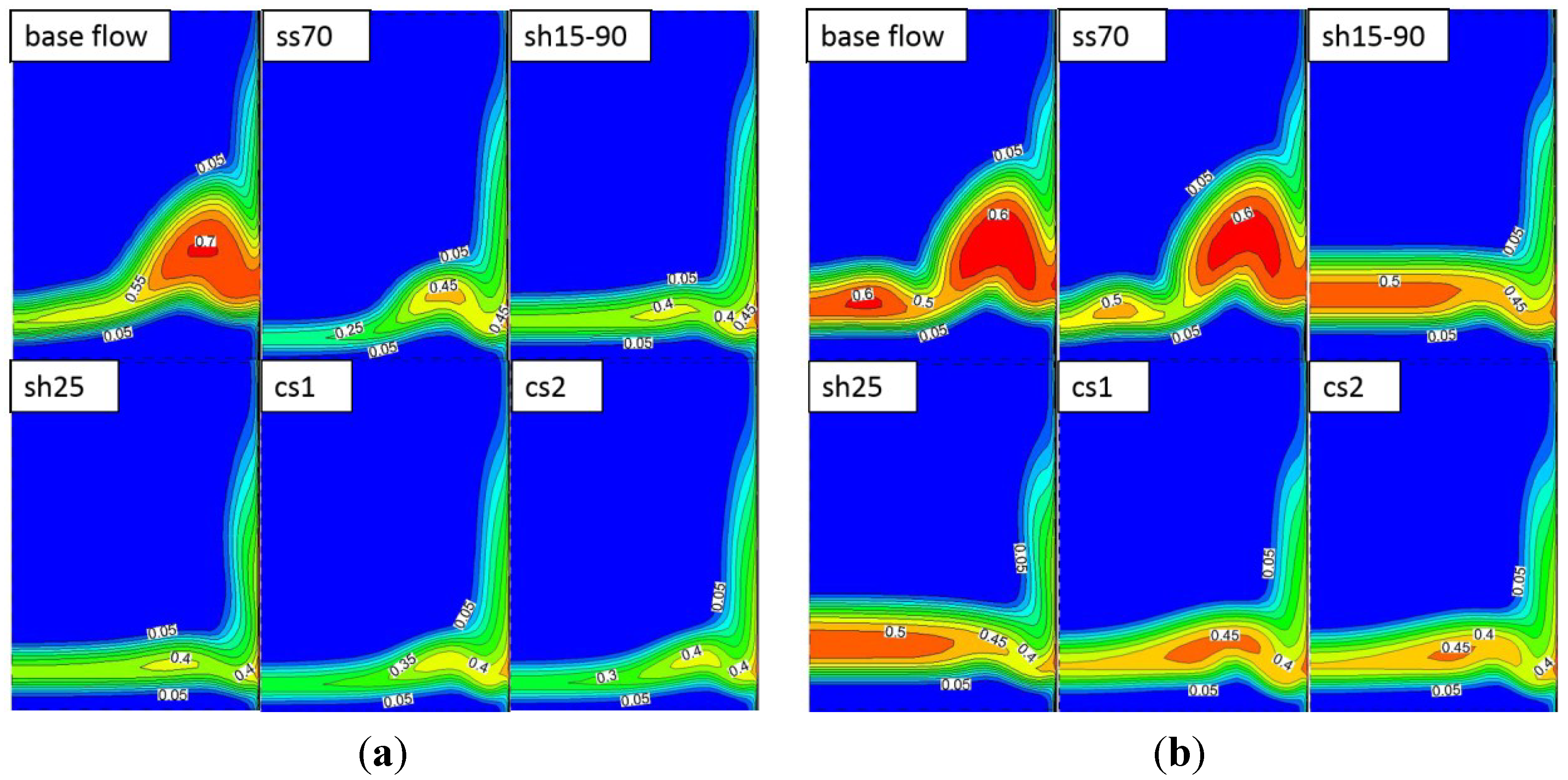
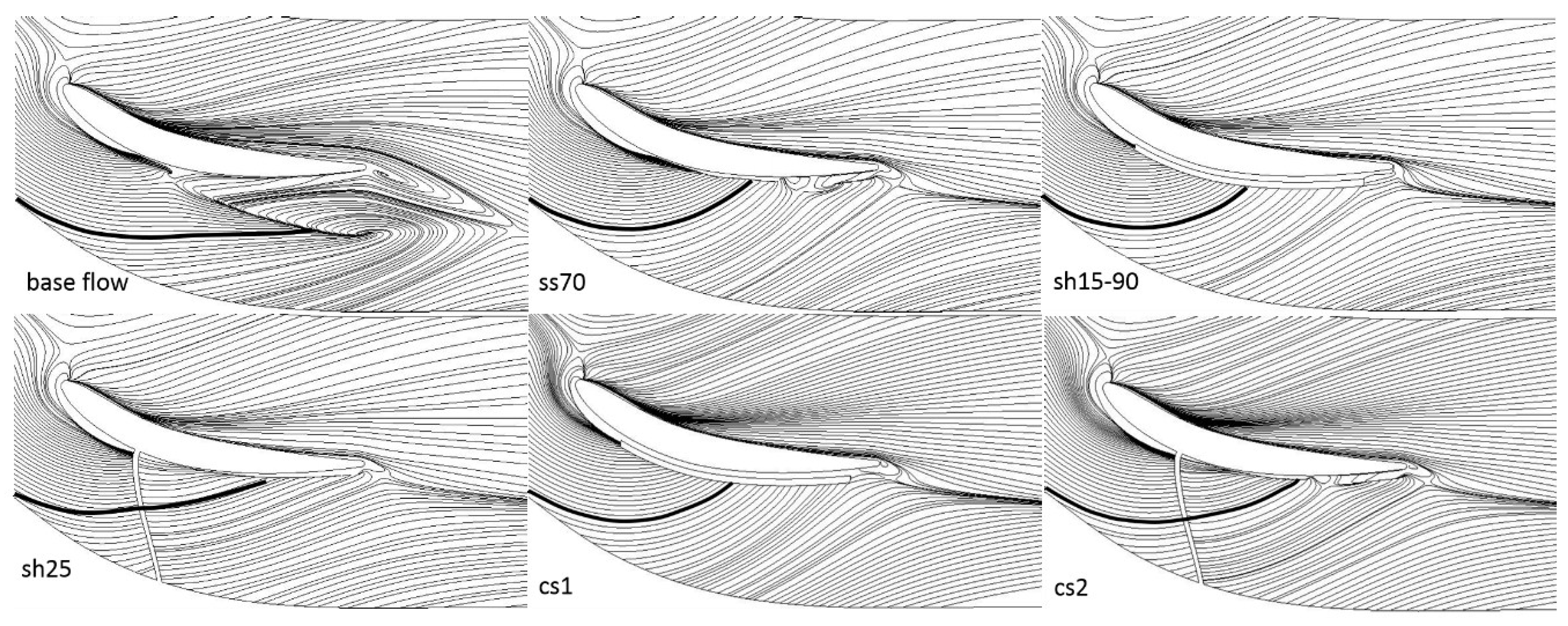
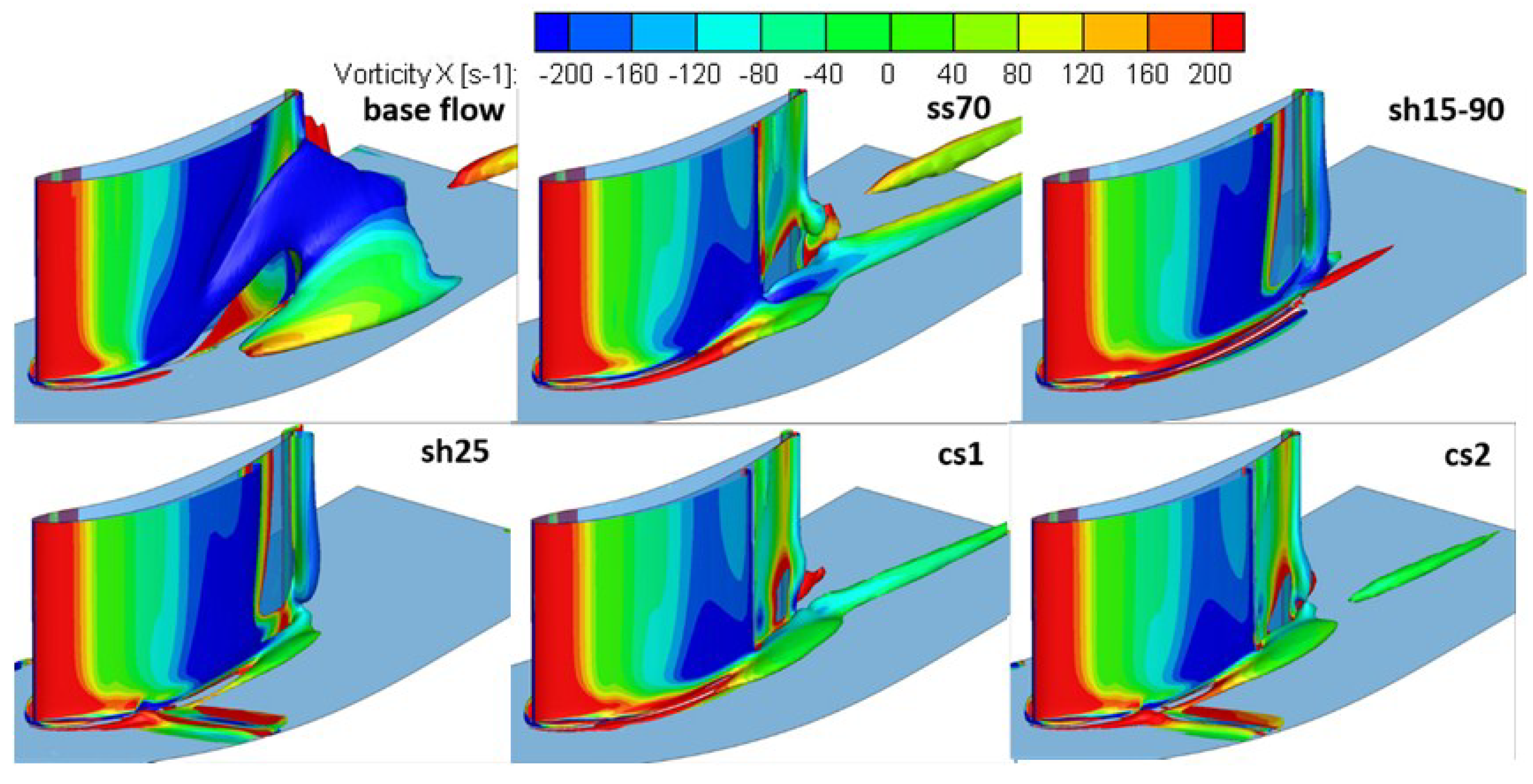
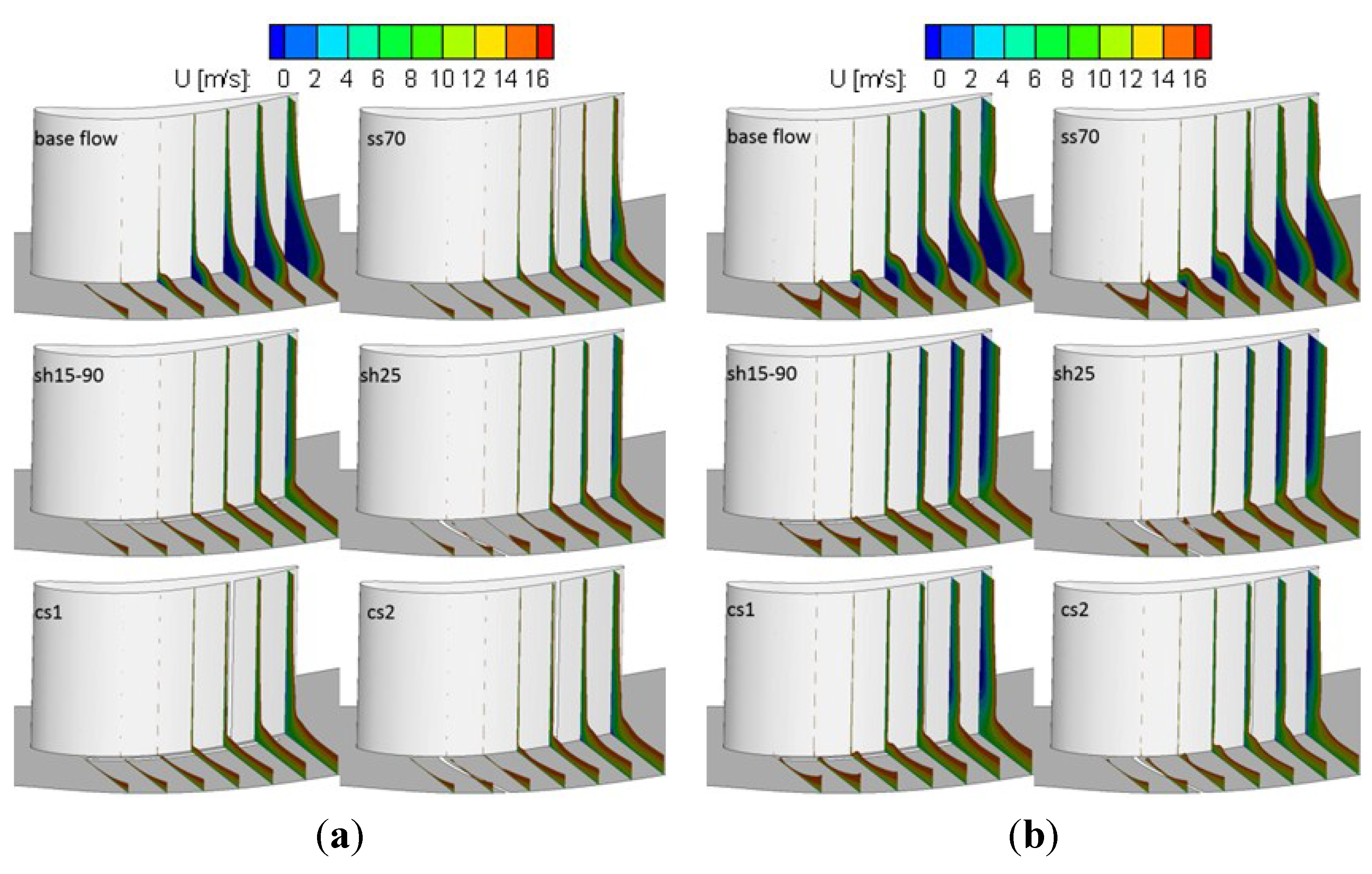
3.3. Effects of BLS Slot Configurations on 3D Flow Field

Figure 10 shows the 3D vortex structure in the cascade passage visualized by the iso-surface of Q [27] which indicates in colors the spanwise vorticity magnitude. For the base flow, the vortex induced by corner separation plays an important role in the passage blockage. The five boundary layer suction configurations can all effectively reduce the size of the corner separation vortex.
Q is defined as:
Q = 1 2 ( Ω i j Ω i j S i j S i j )
where Ω i j = ( u i j u j i ) / 2 and S i j = ( u i j + u j i ) / 2 are respectively the antisymmetric and the symmetric components of the second invariant of velocity gradient tensor u .
Figure 10. 3D vortex structure in flow passage, i = 3 degree (Q = 20,000, colored by axial vorticity).
Energies 07 07994 g010
Figure 11a,b shows the axial velocity distribution in the blade passage at 3 degree and 7 degree incidence, threshold at 17 m/s, to display the passage blockage. Ss70 is shown to be able to suck off the low energy fluid in the corner separation at 3 degree incidence, which leads to a decrease in the boundary layer thickness. With sh15-90, the bulk of the low energy fluid caused by corner separation has been removed. The thickness of boundary layer on the endwall decreases more with sh25. Meanwhile, owing to the corner separation being further restrained, the loss below 25% of span for the two endwall configurations drops greatly, on the other hand, the extent of the low axial velocity region at the mid-span increases compared to the baseline case. This is due to a more uniform spanwise distribution of the passage through-flow that reduces the mid-passage axial flow speed.
Figure 11. Distribution of axial velocity in blade passage: (a) i = 3 degree; (b) i = 7 degree.
Energies 07 07994 g011

4. Conclusions

Numerical simulations were conducted to study the effects of boundary layer suction (BLS) on corner separation in a highly loaded axial compressor cascade. Five suction slot configurations, were investigated under the same suction flow rate conditions. The results are summarized as follows:
(a)
BLS on the blade suction surface or endwall can decrease the total pressure loss and the passage blockage, increase the blade loading and the incidence range on the blades.
(b)
For BLS with the single slot configurations tested, the endwall suction gives better incidence characteristics compared with suction on the blade suction surface, especially at the higher incidence angles. The pitchwise suction slot on the endwall, which is proposed in this paper, shows the best control effects for corner separation over the whole operation incidence among single suction slot configurations.
(c)
The compound suction configurations, with one slot on the blade surface and one on the endwall, show better control effects compared with single suction slot configurations. The proposed compound slot configuration, with one spanwise slot on the blade suction side and one pitchwise slot on the endwall, shows the best control effects for corner separation. A maximum reduction of total pressure of 39.4% was predicted at 7 degree incidence.

Acknowledgments

This work was supported by the National Natural Science Foundation of China (51376001, 51420105008, 51136003), the National Basic Research Program of China (2012CB720205, 2014CB046401), the Aeronautical Science Foundation of China (2012ZB51014), the Beijing Higher Education Young Elite Teacher Project, and the Fundamental Research Funds for the Central Universities. We also thank Aeroengine Simulation Research Center of Beihang University for the permission of using FLUENT. The authors would like to thank the Whittle Laboratory and Rolls-Royce Plc for providing their experimental results. The authors are greatly thankful to the anonymous reviewers for the valuable comments and suggestions that have helped to improve the quality of the paper.

Author Contributions

This paper is a result of the collaboration of all authors. All authors have previous experience on flow control and numerical simulation that have been shared in order to reach the results discussed in the paper. Yangwei Liu and Jinjing Sun meditated this paper. Lipeng Lu has supervised the research work. All authors discussed the results and implications and commented on the manuscript at all stages.

Conflicts of Interest

The authors declare no conflict of interest.

References

  1. Wisler, D.C. Loss reduction in axial-flow compressors through low-speed model testing. J. Eng. Gas Turbines Power 1985, 107, 354–363. [Google Scholar] [CrossRef]
  2. Cumpsty, N.A.; Greitzer, E.M. Ideas and methods of turbomachinery aerodynamics: A historical view. J. Propuls. Power 2004, 20, 15–26. [Google Scholar] [CrossRef]
  3. Costello, G.R.; Cummings, R.L.; Serovy, G.K. Experimental Investigation of Axial Flow Compressor Stator Blades Designed to Obtain High Turning by Means of Boundary-Layer Suction; NACA-RM-E52D18; NASA Lewis Research Center: Cleveland, OH, USA, 1952.
  4. Sinnettej, T.; Costello, G.R. Possible Application of Blade Boundary-Layer Control to Improvement of Design and Off-Design Performance of Axial-Flow Turbomachines; NACA-TN-2371; NASA Lewis Research Center: Cleveland, OH, USA, 1951.
  5. Kerrebrock, J.L.; Reijnen, D.P.; Ziminsky, W.S. Aspirated compressors. In Proceedings of the 1997 International Gas Turbine &Aeroengine Congress & Exposition, Orlando, FL, USA, 2–5 June 1997. ASME Paper 97-GT-525.
  6. Schuler, B.J.; Kerrebrock, J.L.; Merchant, A. Design, analysis, fabrication and test of an aspirated fan stage. In Proceeding of ASME Turbo Expo 2000, Munich, Germany, 8–11 May 2000. ASME Paper 2000-GT-618.
  7. Merchant, A. Aerodynamic design and analysis of a high pressure ratio aspirated compressor stage. In Proceeding of ASME Turbo Expo 2000, Munich, Germany, 8–11 May 2000. ASME Paper 2000-GT-619.
  8. Merchant, A.; Epstein, A.H.; Kerrebrock, J.L. Compressors with aspirated flow control and counter-rotation. In Proceedings of the 2nd AIAA Flow Control Conference, Portland, OR, USA, 28 May–1 June 2004. AIAA Paper No. AIAA-2004-2514.
  9. Merchant, A.; Kerrebrock, J.L.; Adamczyk, J.J. Experimental investigation of a high pressure ratio aspirated fan stage. J. Turbomach. 2005, 127, 43–51. [Google Scholar] [CrossRef]
  10. Qiang, X.Q.; Wang, S.T.; Feng, G.T. Aerodynamic design and analysis of a low-reaction axial compressor stage. Chin. J. Aeronaut. 2008, 21, 1–7. [Google Scholar] [CrossRef]
  11. Song, Y.P.; Chen, F.; Yang, J. A numerical investigation of boundary layer suction in compound lean compressor cascades. In Proceeding of ASME Turbo Expo 2005: Power for Land, Sea and Air, Reno-Tahoe, NV, USA, 6–9 June 2005. ASME Paper 2005-GT-68441.
  12. Chen, F.; Song, Y.P.; Chen, H.L. Effects of boundary layer suction on the performance of compressor cascades. In Proceeding of ASME Turbo Expo 2006: Power for Land, Sea and Air, Barcelona, Spain, 8–11 May 2006. ASME Paper 2006-GT-90082.
  13. Chen, P.P.; Qiao, W.Y.; Liesner, K. Location effect of boundary layer suction on compressor hub-corner separation. In Proceeding of ASME Turbo Expo 2014: Turbine Technical Conference and Exposition, Düsseldorf, Germany, 16–20 June 2014. ASME Paper 2014-GT-25043.
  14. Liesner, K.; Meyer, R.; Schulz, S. Non-symmetrical boundary layer suction in a compressor cascade. J. Theor. Appl. Mech. 2012, 50, 455–472. [Google Scholar]
  15. Guo, S.; Chen, S.W.; Song, Y.P. Effects of boundary layer suction on aerodynamic performance in a high-load compressor cascade. Chin. J. Aeronaut. 2010, 23, 179–186. [Google Scholar] [CrossRef]
  16. Guo, S.; Chen, S.W.; Lu, H.W. Enhancing aerodynamic performances of a high-turning compressor cascade via boundary layer suction. Sci. China Technol. Sci. 2010, 53, 2748–2755. [Google Scholar] [CrossRef]
  17. Guo, S.; Lu, H.W.; Chen, F. Vortex Control and Aerodynamic performance improvement of a highly loaded compressor cascade via inlet boundary layer suction. Exp. Fluids 2013, 54, 1–11. [Google Scholar] [CrossRef]
  18. Zhang, L.X.; Chen, S.W.; Xu, H. Effect of boundary layer suction on aerodynamic performance of high-turning compressor cascade. In Proceeding of ASME Turbo Expo 2013: Turbine Technical Conference and Exposition, San Antonio, TX, USA, 3–7 June 2013. ASME Paper2013-GT-94907.
  19. Ding, J.; Chen, S.W.; Xu, H. Control of flow separations in compressor cascade by boundary layer suction holes in suction surface. In Proceeding of ASME Turbo Expo 2013: Turbine Technical Conference and Exposition, San Antonio, TX, USA, 3–7 June 2013. ASME Paper 2013-GT-94723.
  20. Cao, Z.; Liu, B.; Zhang, T. Control of separations in a highly loaded diffusion cascade by tailored boundary layer suction. Proc. Inst. Mech. Eng. C J. Mech. Eng. Sci. 2014, 228, 1363–1374. [Google Scholar] [CrossRef]
  21. Gbadebo, S.A.; Cumpsty, N.A.; Hynes, T.P. Control of three-dimensional separations in axial compressors by tailored boundary layer suction. J. Turbomach. 2008, 130, 011004.1–011004.8. [Google Scholar] [CrossRef]
  22. Liu, Y.W.; Yu, X.J.; Liu, B.J. Turbulence models assessment for large-scale tip vortices in an axial compressor rotor. J. Propuls. Power 2008, 24, 15–25. [Google Scholar] [CrossRef]
  23. Liu, Y.W.; Lu, L.P.; Fang, L. Modification of Spalart–Allmaras model with consideration of turbulence energy backscatter using velocity helicity. Phys. Lett. A 2011, 375, 2377–2381. [Google Scholar] [CrossRef]
  24. Khalid, S.A.; Khalsa, A.S.; Waitz, I.A. Endwall blockage in axial compressors. J. Turbomach. 1999, 121, 499–509. [Google Scholar] [CrossRef]
  25. Gbadebo, S.A.; Cumpsty, N.A.; Hynes, T.P. Three-dimensional separations in axial compressors. J. Turbomach. 2005, 127, 331–339. [Google Scholar] [CrossRef]
  26. Duan, Z.Z.; Liu, Y.W.; Lu, L.P. Effects of tip clearance size on flowfield in a low-speed axial compressor rotor. Appl. Mech. Mater. 2014, 543, 158–163. [Google Scholar] [CrossRef]
  27. Debief, Y.; Delcayer, F. On coherent-vortex identification in turbulence. J. Tuebulece 2000, 1, 1–22. [Google Scholar]

