Wireless Mesh Networking: An IoT-Oriented Perspective Survey on Relevant Technologies


Internet of Things (IoT) Lab, Department of Engineering and Architecture, University of Parma, Parco Area delle Scienze 181/A, 43124 Parma, Italy
*
Author to whom correspondence should be addressed.
Future Internet 2019, 11(4), 99; https://doi.org/10.3390/fi11040099
Submission received: 7 February 2019
/
Revised: 30 March 2019
/
Accepted: 10 April 2019
/
Published: 17 April 2019
(This article belongs to the Special Issue 10th Anniversary Feature Papers)
Abstract
:The Internet of Things (IoT), being a “network of networks”, promises to allow billions of humans and machines to interact with each other. Owing to this rapid growth, the deployment of IoT-oriented networks based on mesh topologies is very attractive, thanks to their scalability and reliability (in the presence of failures). In this paper, we provide a comprehensive survey of the following relevant wireless technologies: IEEE 802.11, Bluetooth, IEEE 802.15.4-oriented, and Sub-GHz-based LoRa. Our goal is to highlight how various communication technologies may be suitable for mesh networking, either providing a native support or being adapted subsequently. Hence, we discuss how these wireless technologies, being either standard or proprietary, can adapt to IoT scenarios (e.g., smart cities and smart agriculture) in which the heterogeneity of the involved devices is a key feature. Finally, we provide reference use cases involving all the analyzed mesh-oriented technologies.
1. Introduction
In the current era, the fourth industrial revolution and new generation wireless communication technologies are enabling pervasive connectivity between objects. These communication systems, involved in the so called “network of networks” Internet of Things (IoT), will eventually allow humans to interact with billions of devices, including sensors, actuators, services, and other connected objects, in an Internet-like way, with a forecast of more than 40 billion connected (with short-range radio communication technologies) “things” by 2020 [1] (and more than 125 billion by 2030 [2]), and more than 2.7 billion Low Power Wide Area Network (LPWAN) connections by 2029 [3].
In this context, connected things are generally defined as Smart Objects (SOs) and, thanks to the IoT, dynamically integrated in several scenarios, such as: smart industries applications, smart cities, smart agriculture, smart health, etc. Each application area has specific requirements to be taken into account, thus having implications for the communication technologies to be considered and, possibly, adopted. In particular, IoT-related wireless technologies developed in recent years are extremely heterogeneous in terms of protocols, performance, reliability, latency, cost effectiveness, and coverage. For instance, some of them are designed for short-range radio communications (e.g., Bluetooth and ZigBee), others are more suitable to cover wide areas with very small bandwidth (e.g., Sub-GHz), while others are designed for middle-range communications and high transmission rate (e.g., IEEE 802.11). Moreover, IoT network topologies are generally star- or tree-based, with data collected by groups of sensors and sent to a central collector or border router, in order to guarantee centralized processing. The emerging and constantly evolving IoT applications require more complex network topologies, without a predefined hierarchy but able to dynamically adapt themselves to changing conditions. For this reason, there is a strong academic and industrial interest on the development of hardware and protocols able to support Wireless Mesh Networks (WMNs).
In mesh topologies, network nodes are directly and dynamically connected in a non-hierarchical way, thus allowing many-to-many communications (among nodes cooperating with each other) to efficiently route data from a generic source to a generic destination. In fact, in a WMN each node composing the network can operate both as a host and as a router, relaying packets sent by other nodes when the destination is not in the visibility range of the source. Moreover, mesh networks do not require an infrastructure, since they dynamically self-organize and configure themselves, with consequent relevant advantages, in terms of: (i) deployment, installation and maintenance’s overhead and cost reduction; (ii) dynamic workload distribution; (iii) better reaction to node failures; and (iv) easy network topology modification. The organization of a WMN is generally handled through the definition of a routing policy shared among all nodes, aiming at discovering and determining the best routes, on the base of different metrics (e.g., throughput, link quality, hops number, etc.) measured on data streams. Therefore, streams of data in WMNs cross all nodes connecting the source and the destination.
Mesh topologies are thus the most attractive alternative to traditional centralized or tree-based network topologies, where nodes are directly linked to small subset of other nodes and the links between these infrastructure neighbors are hierarchically organized. While star- and tree-oriented topologies are very well established, highly standardized and vendor-neutral, in the case of mesh networks the research community and vendors have not yet all agreed on common standards, with the interoperability among devices from different vendors seldom assured. Moreover, comprehensive surveys on available options in the field of mesh networks for IoT are lacking in the literature.
In this paper, we aim at highlighting how a mesh network can be built under heterogeneous communication technologies, thus providing a comprehensive survey of relevant wireless communication technologies which can be employed in different IoT scenarios, namely: IEEE 802.11-based, Bluetooth, IEEE 802.15.4-based, and LoRa. We analyze these protocols from the point of view of their support to mesh networking, either as native applications or by proper adaptation. To provide a global vision of the state of the art on WMNs, our survey includes both standard and academic/industrial solutions.
The remainder of this paper is organized as follows. In Section 2, a preliminary overview on the most important routing protocols for ad hoc networks is provided. Section 3 presents a survey of mesh networking in the field of Wi-Fi-based communications. Section 4 provides an in-depth survey of Bluetooth-based mesh networking solutions, while Section 5 reviews the most adopted IEEE 802.15.4-based protocols for mesh networks. In Section 6, we provide a review of mesh networking mechanisms based on LoRa transmissions. In Section 7, we first illustrate two reference use cases involving all the proposed transmission technologies and, then, we present a comparison between the various mesh technologies. Finally, concluding remarks are provided in Section 8.
2. Preliminaries on Routing Protocols for Ad-hoc Networks
Key features of a mesh network, both wired and wireless, are flexibility and self-organizing capability. To build multi-hop routes and to define the network topology, a mesh network needs a routing protocol to rely on. Such protocol can be derived from routing protocols for ad hoc networks, that can be in turn classified as proactive and reactive protocols. Proactive routing protocols are characterized by the fact that each node is in charge of maintaining single or multiple routing tables to represent the entire network topology (or a portion of it). Therefore, proactive routing protocols are known as “table-driven”, meaning that routing information for each tuple of nodes are continously updated, thus maintaining the routing table updated. Generally, proactive routing protocols are used for networks with a small number of nodes. One of the most known proactive routing protocol examples is represented by the Destination Sequence Distance Vector (DSDV) protocol [4].
At the opposite, reactive routing protocols build multi-hop routes only upon specific requests and are thus characterized by a reduced overhead. They are based on the concept of flooding and involve three main phases: (i) route discovery, needed to find a possible existing route toward an unknown destination; (ii) route maintenance, used to detect link breaks and to find alternative routes; and (iii) an incremental search method to limit the number of links traversed when routing discovery is enabled. In this kind of networks, nodes that are not actively involved in communication flows do not generate any control or routing information traffic. Moreover, a route is maintained alike as long as it is needed by the source node. Among all available reactive routing protocols, the well-known ones are represented by the Dynamic Source Routing (DSR) protocol [5] and the Ad hoc On-Demand Distance Vector Routing Protocol (AODV) [6].
2.1. Ad hoc On-Demand Distance Vector Routing Protocol
The AODV protocol is a reactive routing protocol developed for ad hoc networks, which supports unicast, multicast, and broadcast communications. The first phase in the AODV protocol is the discovery: a source node S, which has no entry, in its routing table, corresponding to the address of the destination node D, generates control traffic according to the following steps.
- The source node S broadcasts a Route REQuest (RREQ) packet, whose main fields are the destination address and hop counter, to its n neighbors , , ⋯, .
- Upon reception of a RREQ packet, a node checks if the packet contains routing information related to the destination. If so, it rebroadcasts the RREQ increasing the hop counter. If the node itself is the destination of the packet, it replies to the source with a Route REPly (RREP) message.
- Finally, the source node S builds its routing table on the basis of the received RREP messages, storing the next-hop to each destination, and uses this information for following transmissions.
It follows that before starting the communication with the destination node D, the source node S has to wait for the completion of the ongoing route discovery process.
One of the key features of the AODV protocol is represented by the destination sequence number, used also to have loop-free routes. This number is generated by each node in order to maintain the entries of the routing tables updated and is useful if there are two different routes from a source S to a destination D: in this case, S selects the route associated with the largest destination sequence number. Another interesting feature of the AODV protocol is the management of the local connectivity, in order to detect a route break, since nodes’ mobility has to be taken into account as well. This mechanism works in the following way: in case a node, within a specific interval, does not highlight its presence to its neighbors through a specific hello interval, then, through a RREP message, it broadcasts a special request containing its identity, thus forcing a discovery phase. In detail, if a relay node between S and D fails to receive a minimum amount of hello messages—denoted as allowed hello loss, then a list of all the destinations which are unreachable due to the link loss will be forwarded by a broadcast Route Error (RERR) message by the node upstream of the break (propagating back to S, the latter has the possibility to perform again the route discovery process if it still needs the route). Thanks to these mechanisms, the AODV protocol has the capability of quickly adapting to dynamic link conditions, and can be employed with low processing power devices, as it has a reduced network utilization and memory overhead.
2.2. Optimized Link State Routing (OLSR) Protocol
The Optimized Link State Routing Protocol (OLSR) is a proactive routing protocol designed to work with large and dense Mobile Ad-Hoc NETworks (MANETs) and using a hop-by-hop strategy to achieve a performance optimization higher than other classic link state routing algorithms. OLSR has been designed to work in dynamic scenarios where the communicating peers change over time and, since routes are maintained for all known destinations at all times [7], the control packets in the network are very limited and are usually handled only by selected nodes, denoted as MultiPoint Relays (MPRs)—key element of the OLSR protocol—whose tasks are: (i) route creation and selection, and (ii) relay of messages between nodes.
In detail, a MPR reduces redundant retransmissions in the network region it is handling, thus minimizing the overhead of flooding messages. In general, a node obtains the information about its neighbors through periodic hello messages received from the neighbors themselves. A generic intermediate node selects a set of nodes at 1-hop distance as its MPRs. Then the MPRs advertise link-state information for their “child” nodes periodically in their control messages. OLSR uses packets encapsulated in UDP datagrams transmitted on the reserved port 698. Moreover, the packet format is unified for all data (control messages, actual data messages) in order to have a fast and easy extensibility of the protocol maintaining compatibility with older versions of the protocol itself.
2.3. Dynamic Source Routing (DSR) Protocol
The Dynamic Source Routing (DSR) protocol is a reactive routing protocol, similar to AODV, specifically designed for use in multi-hop wireless ad hoc networks composed of mobile nodes. Since DSR adheres to the source routing philosophy, it does not use any periodic routing advertisement. This feature leads to a reduction of the control messages in the network—ideally to zero: when all nodes are stationary with respect to each other and all routes for current communication have already been discovered, there is no need for any route discovery process. A DSR-based network is completely self-organizing and self-configuring, thus requiring no existing network infrastructure, since nodes cooperate to forward packets over multiple hops between nodes not placed in visibility. The DSR protocol is based on: (i) route discovery—when a source node S wants to send a packet to a destination node D and does not know a route to D, it sends a route request that will be filled by each intermediate node with the hops the packets have to follow to go from S to D; and (ii) route maintenance—used when the data are actually transmitted and to detect network topology changes (e.g., a link along a route no longer works) using an acknowledgement-based system. In particular, when a source route is indicated as broken, the node S can use any other known route (which are cached in the node) to D, or it can start a route discovery to find a new route to D. Focusing on the route maintenance, thanks to the caching mechanism of the routes, DSR-based nodes have a rapid reaction to topology changes. In fact, a node with multiple routes to a destination can try another cached route if the used one fails. In this way, there is no need for a new route discovery procedure, leading to a significant reduction of control messages across the network.
3. Mesh in IEEE 802.11 Networks
3.1. Standard: IEEE 802.11s
3.1.1. IEEE 802.11s Basics
In the last decade, a growing interest in mesh networking, from both academic and industrial entities, brought to the definition of an IEEE 802.11 standard amendment [8], specifically addressed to IEEE 802.11 mesh networks, denoted as IEEE 802.11s [9,10]. The physical layers of IEEE 802.11s and IEEE 802.11 standards are the same: it introduces new routing procedures that are performed at the Medium Access Control (MAC) layer, rather than at the network layer. To have an efficient routing, the nodes must have an accurate knowledge of the wireless links connecting them to their 1-hop neighbors. This leads to a seamless routing for protocols of the higher layer. In an IEEE 802.11s mesh network, also named as Mesh Basic Service Set (MBSS), there are different logical components, as shown in Figure 1. The main ones are the mesh stations (mesh STAs) that can participate to the formation of the MBSS, in which each node has the same level of complexity and there is no hierarchical structure. The mesh STAs, moreover, participate to the path selection and forwarding, leading to a very simple self-organizing network. In case of integration with other type of networks, such as the “traditional” IEEE 802.11 infrastructure BSS, or if the MBSS has to access external networks, other logical components are needed; the one that guarantees the access to the mesh network for “traditional” IEEE 802.11 stations is named as Mesh APs (MAPs). A MAP, however, does not enable the communication between a mesh STA and a non-mesh STA. In fact, the logical component that enables the integration between mesh BSS and infrastructure BSS—thus enabling the communication between mesh STAs and non-mesh STAs—is the mesh gate. Furthermore, in order to enable also the communication between the mesh BSS and non-IEEE 802.11 Local Area Networks (LANs), such as wired LAN, other logical components are used, namely the Mesh Portal Points (MPPs), which enable the communication with an external entities.
Compared with a traditional IEEE 802.11 network, the IEEE 802.11s mesh solution—this is valid for wireless mesh networks in general—has some advantages: (i) it enables rapid and low-cost back-haul deployment; (ii) it provides coverage in scenarios hard to wire; (iii) it is self-organizing and extensible—the addition of a node simply extends the network and, thanks to the routing algorithm, the network can quickly adapt to the new conditions; and (iv) it can have a greater coverage, exploiting multi-hop forwarding. At the opposite, there are also some drawbacks: (i) the data rate decreases with the number of hops, and (ii) the wireless medium is in general less reliable than the wired medium. Thus, when deploying an IEEE 802.11, all these aspects must be taken into account. In general, since our view is IoT-oriented, the mesh solution is preferable, since a WSN can have advantages in terms of scalability, flexibility, costs and simplicity of deployment of a WMN.
3.1.2. IEEE 802.11s Topology Formation
The topology formation of an IEEE 802.11s-based network is based on the transmission of messages, called beacons, carrying information about the network itself. As in other routing protocols, the first phase of the network creation is the discovery phase, which follows two possible approaches: (i) passive scanning of the beacon frames or (ii) active scanning probe frames. During the discovery procedure, each mesh STA transmits beacon frames—which are used also for topology maintenance and synchronization—and responds with probe response frames when a probe request frame is received. In this way, the neighbors of the mesh STA become aware of the presence of a particular mesh node around them. One of the most important value that is carried in the beacons and in the probe response frames is the Mesh ID, which is used to identify the mesh BSS. Once a mesh station identify the correct node, the link is established and maintained through the Mesh Peer (Link) Management (MPM) protocol [8], until mesh stations are in visibility and share a common profile.
3.1.3. IEEE 802.11s Routing Algorithm
The default routing protocol for IEEE 802.11s is the Hybrid Wireless Mesh Protocol (HWMP) [11]. However, the IEEE 802.11s standard does not force to use this protocol, which can then be replaced by other algorithms. HWMP provides both proactive and reactive path selection—for this reason it is called hybrid—and is based on the AODV protocol, properly adapted to support MAC layer routing, together with a tree-based, proactive mechanism, where a mesh station—that generally works as as MPP—forwards control messages to other mesh stations. The discovery phase depends on the operating mode of the algorithm: if a mesh node is working in an on-demand mode, the network is flooded with RREQ messages to discover the route towards a specific destination; if, instead, the mesh node is working in proactive mode, there can be two strategies: (i) RREQ messages are periodically sent in order to keep all routes updated; (ii) RREQ messages, denoted in this case as Root Announcement (RANN), flood the network in order to provide information on how to reach a root node. However, this algorithm has been in the years substituted by other solutions, based on AODV and OLSR, which are discussed in the following; the most relevant are Better Approach To Mobile Ad-hoc Networks (B.A.T.M.A.N.) and Babel.
3.2. Other Solutions
3.2.1. Better Approach To Mobile Ad-hoc Networks (B.A.T.M.A.N.)
B.A.T.M.A.N. advanced (batman-adv in the following) is a proactive routing protocol designed for WMNs that became popular in last years thanks to the fact that it is already available in the Linux kernel. It is the “wireless” version of B.A.T.M.A.N. protocol, originally designed for wired networks and works at MAC layer instead of network layer. The batman-adv approach allows each node, for each destination in the mesh network, to determine its best next-hop—thus, there is no need for route discovery but, rather, for neighbor discovery—without requiring the knowledge of the complete topology of the network, leading to a significant reduction of control messages in the network.
In our description, we refer to the batman-adv version V. To discover neighbors, nodes regularly send in broadcast an OriGinator Message version 2 (OGMv2, OGM in the following), depicted in Figure 2, applying a a delay to avoid packet collisions [12]. The OGM format comprises several fields, such as a sequence number (used to detect new OGMs and avoid that OGMs are counted twice), throughput, and optional flags (e.g., to set a node as a gateway towards an external network). In batman-adv V, the neighbor discovery is handled by the Echo Location Protocol (ELP), whose details, to best of the authors’ knowledge, are not up publically available since they are not up to date with the last versions of the protocol. However, in principle this packet type is never forwarded or re-broadcasted in the mesh and the OGM flooding protocol is used to determine the link quality, based on the throughput of the link itself, and remains responsible for mesh routing.
Dividing the phase of the discovery and the phase of routing leads to: (i) reduced overhead, as OGMs interval can be incresed; (ii) neighbor discovery and metric estimation are performed separately.
The previous version of batman-adv, namely B.A.T.M.A.N. IV, used a packet loss-based metric: however, this metric is not fit to handle the increasing number of devices. For this reason, in batman-adv a throughput metric was introduced. Depending on the link type, batman-adv is able to determine the throughput exploiting the features of the used radio interface (whose driver provides the estimated throughput for each neighbor node) or evaluated directly from batman-adv protocol running a “throughput meter” test. Finally, the overall path throughput between a source node S and a destination node D is computed as the minimum between the throughput of all available paths.
3.2.2. Babel Routing Protocol
Another routing algorithm developed for mesh networks is Babel, a network layer distance-vector routing protocol based on a distributed version of the Bellman-Ford algorithm [13,14]. Babel uses a mechanism originally developed for the Enhanced Interior Gateway Routing Protocol (EIGRP) [15], known as “feasibility”, that avoids routing loops and, therefore, makes counting to infinity impossible. The drawback of the “feasibility” mechanism is that it can happen that a route is rejected also if it is loop-free. To avoid this problematic behavior, the “feasibility” method is combined together with another mechanism developed in the Destination Sequenced Distance Vector Routing (DSDV) [4], known as “sequenced routes”. This mechanism avoids the “starvation” of a route happening when a router rejects all routes to a given destination, even those that are loop-free. However, in DSDV implementation, the sequenced routes algorithm is slow to react to a starvation episode. In Babel, instead, starvation recovery is accelerated by using explicit requests (known as “seqno requests” in the protocol) that signal a starvation episode and cause new sequenced route to be propagated in a periodic way.
Babel relies on the computation, made by every pair of neighboring nodes A and B, of the link cost among A and B. Given a route between any two nodes, the route metric corresponds to the sum of the costs of all the links connecting A to B. However, Babel does not specify any algorithm for computing metrics and existing implementations are based on packet-loss metric on wireless links and a simple hop-count metric on all other types of links [16]. The goal of the Babel algorithm is to compute, for each source node S, the routes of lowest cost to S. In detail, a Babel node periodically broadcasts hello messages, embedded in UDP datagrams, to all of its neighbors, together with an I Heard You (IHU) message to every neighbor from which it has recently heard an hello. From the information retrieved from hello and IHU messages (whose packets are shown in Figure 3b and Figure 3c, respectively) received from B, node A computes the cost of the link from A to B. A key feature of Babel is its fast reaction to network changes; this is obtained through triggered updates, triggered retractions and explicit requests, in which a Babel node requests an action to be done from another node or a set of nodes.
The main Babel packet, shown in Figure 3a, contains the following fields: (i) magic number, set to the arbitrary value 42 and identifying the Babel packet; (ii) version, identifying the adopted version of the Babel routing protocol; and (iii) body length, containing the length (in bytes) of the body following the packet header. The body is basically composed by a sequence of Type-Length-Value (TLV) tuples, each of them composed by the following fields: (i) type of TLV (e.g., hello pr IHU messages); (ii) length of the body, considering only the Type and Length fields; and (iii) the TLV’s payload, consisting of a body and, potentially, a list of sub-TLVs. The structure is, thus, somehow modular and the packet can be extended easilly in order to support new functionalities. Among the available TLV types, the two most relevant, being responsible for route creation, are the hello and IHU packets, shown in Figure 3b and Figure 3c, respectively. The hello TLV is used for neighbor discovery and for calculating the cost of a link and is, in turn, composed by the following fields: (i) type—corresponding to the value 4 in the case of hello TLV; (ii) length of the body; (iii) flags to handle the hello TLV, e.g., to determine a unicast or a multicast transmission; (iv) sequence number—which is increased every time an hello packet is sent; and (v) time window, after which the originator node will send a new hello packet. In an IHU packet, the type field is set to 5 and the remaining fields are shown in Figure 3c. Among the fields, the most relevant is the “Rx Cost”, since it carries informations about the cost of the link between two nodes. Other TLV types are: Router-Id, Next Hop, Update—the latter is used to force the request for an update of the route. The union of all available TVL packets “attached” in the main Babel packet makes this routing protocol easily extensible and customizable, leading to new solutions such as a new delay-based metric for route selection [16] and Type of Service (ToS)-based routing [17,18]. Finally, since Babel is based on periodic routing table updates, it is not adequate [19] for: (i) large stable networks—since sending periodic updates even in the absence of topology changes increases the amount of control packets in the network, which can be reduced by using a protocol that relies on a reliable transport (such as Open Shortest Path First (OSPF) [20,21], Intermediate System to Intermediate System (IS-IS) [22] or EIGRP) or DSR; and (ii) low-power networks, since periodic updates use battery power even when there are no topology changes and no user traffic—this makes Babel wasteful in low-power networks.
3.3. Applications
IEEE 802.11-based mesh networks have been used for several applications, both alone or in combination with other radio technologies. For example, the use of IEEE 802.11 mesh networks has been investigated for indoor positioning, in combination with Ultra-Wide Band (UWB) technology [23]. In particular, an IEEE 802.11-based mesh backbone is used in in [23] to combine its high data-rate feature together with high-accuracy UWB-based localization, since it allows an easy and fast deployment in areas without existing infrastructures. Video surveillance scenarios have also been studied in the literature, using IEEE 802.11 mesh networking as enabling technology. In [24], a video surveillance system for a large outdoor area based on an IEEE 802.11s mesh network is described. More in detail, the authors mount a camera on a drone moving over the area of interest and sending the video to a control center. As the drone is a mobile node and is not always in visibility with the control center, some static IEEE 802.11s nodes are deployed on the ground guaranteeing mesh connectivity. In [25], a wide area surveillance mesh network aimed at preserving forests from fire is presented. The proposed system is based on an IEEE 802.11-based mesh network, which supports communications both inside and outside the area afflicted by the fire, thus enabling the surveillance of the environment and guaranteeing the communication between the nodes in the area.
Other relevant results can be found for smart city scenarios, for example aiming at controlling street lights in order to reduce energy consumption [26]. In [27], the smart city intelligent transportation problem is considered and the authors propose an application scenario that utilizes a swarm of autonomous drones to assist transportation of emergency medical teams, and other entities in emergency situations (e.g., accidents or natural disasters). Their goal id to provide in a fast way a response to an emergency crisis, enabling communication between the participating smart vehicles and, then, helping in the following restoration actions. More in detail, the authors use IEEE 802.11p for the communications between vehicles and drones; and IEEE 802.11s to support the internal drone communications, building a drone-based Wi-Fi backhaul network. In [28], the focus is also on the intelligent transportation problem in smart city scenarios, suggesting IEEE 802.11s as the solution to connect autonomous vehicles as mobile nodes of a mesh network.
Finally, IEEE 802.11-based mesh has been deployed to enable new scenarios in aerospace applications [29], with a comparison between HWMP, batman-adv, and other technologies, (e.g., WiMax). In [29], the authors conclude that both HWMP and batman-adv have significant flaws in terms of re-organization velocity and scalability. In the authors’ opinion, wireless mesh networking is suitable for both non-critical and critical space applications and the ongoing research should focus on the development of more robust open source solutions, taking into account an improvement of the network performance.
4. Mesh in Bluetooth/BLE Networks
4.1. Standard
Among the different releases of the Bluetooth protocol, the Bluetooth Low Energy (BLE) corresponds to its low-power variant and is a promising technology which allows to build low-power and low-cost networks composed by a large amount of nodes. BLE is presently raising more and more attention and is becoming one of the leading technologies for both IoT-oriented and industrial scenarios. Moreover, the relevance of BLE technology is due to the fact that it can be found as a natively implemented feature in the majority of current devices (e.g., laptops, smartphones, mobile tablets, and other smart devices), thus enabling users to interact with environmental BLE objects without the use of additional gateways. Despite that, most applications developed in last years focus on different network topologies, either point-to-point or star-based, where the smart device (i.e., a smartphone or another BLE-enabled device) acts as the center of the network. Looking at the technological aspects, BLE may be described as a short-range technology: in order to cover large areas or to allow complex networking behaviors, a multi-hop network is required. Therefore, BLE has recently shown a great attention even for its use as a reference technology to build mesh networks, in order to enable many-to-many communications in network scenarios. Hence, this general interest has led to the definition of a plethora of proprietary BLE-oriented networking solutions that generally lack of interoperabilty due to missing common mesh standards [30,31,32,33]. A first change happened in 2017 thanks to the release of the official Bluetooth mesh networking standard specifications [34] by the Bluetooth Special Interest Group (SIG).
With respect to the original and classical version of the Bluetooth protocol, able to achieve high-speed transmission, the low-power BLE protocol aims at significantly reducing the power consumption of a BLE node itself. Moreover, it is notable that BLE-enabled devices (especially those oriented to IoT) are generally battery-powered (by coin-cell batteries) and should operate for a long time (e.g., several years) with a limited duty cycle without the need for replacing the internal battery. Similarly to the classic Bluetooth, BLE uses frequencies in the range of 2402–2480 MHz, thus working in the 2.4 GHz band; at the opposite, BLE is provided with 40 2 MHz-spaced channels.
Looking at the operating plane, BLE provides two different communication ways among the devices participating to the communication: (i) advertising mode, in which a BLE node broadcasting packets allows its neighbors (within its transmission range) to receive the transmitted data; and (ii) connection-oriented mode, where the packet transmission happens only between two BLE nodes which, through a handshake, establish a direct connection. Focusing on these modes, in 2013 the iBeacon protocol [35] has been announced by Apple with the goal of building applications and services in a location-aware fashion. Hence, in order to mark a BLE advertising packet as an iBeacon message, it has to contain the following information (useful for identifying the specific iBeacon device which sent the iBeacon message): (i) a 16-byte Universally Unique IDentifier (UUID), and (ii) two 2-byte fields identifying Major and Minor identifiers.
Even though both advertising and connection-oriented communication strategies can be used to implement a BLE mesh network, the SIG selected the former one as backbone mode for the mesh standard. In the BLE standard, nodes composing the mesh network are denoted as “nodes” and those which are not are called “unprovisioned devices”. The process which transforms an unprovisioned device into a node is called “provisioning”: this is a secure procedure resulting in an unprovisioned device getting a series of encryption keys and being known to the Provisioner device (typically a tablet or a smartphone). One of these keys is called NetKey and all nodes in the mesh network must possess at least one NetKey, as the possession of this key (together with other requirements) makes a device a member of the network and, namely, a node. Some BLE nodes can have multiple constituent parts, each of which can be independently controlled. In Bluetooth Mesh terminology, these parts are called “elements”. An example of a BLE device with multiple elements can be a LED lighting product which, if added to a Bluetooth mesh network, would form a single node with three elements, one for each individual LED light.
Communication in the mesh network is message-oriented. Messages exchanged between nodes can have different types, each one with a defined unique “opcode”. Moreover, messages can be acknowledged or unacknowledged. An acknowledged message requires a response from the node that receives it, which has two purposes: (i) it confirms that the message has been received and (ii) it returns data to the sender, if needed. The sender of an acknowledged message may resend the message if it does not receive the expected response(s) and, therefore, acknowledged messages must be idempotent. This means that the effect of a given acknowledged message, arriving at a node multiple times, will be the same as it had only been received once. Unacknowledged messages, instead, do not require any response.
Messages must be sent by nodes to an address. The Bluetooth Mesh standard defines the following three types of addresses.
- Unicast address, identifying a single element or a node in the network in a unique way. A unicast address is assigned to a device during the provisioning process, when it becomes part of the network.
- Group address, corresponding to a multicast address able to represent either a single element or node, as well as multiple elements or nodes. Moreover, group addresses can be either assigned dynamically (i.e., established by the user via a configuration application), as well as fixed by the official SIG group (in this case, denoted as SIG Fixed Group Addresses).
- Virtual address, corresponding to a 128-bit UUID that can be assigned to either one or more elements, as well as to a single or multiple nodes.
The Bluetooth Mesh standard architecture follows, as communication paradigm, the publish/subscribe model, in which the publisher node sends its data on a well-defined topic, while several subscriber nodes, manifesting their interest in such data information, listen to one or more of the available topics. Moreover, nodes are thus configured to select messages sent to specific addresses for processing, and in the Bluetooth Mesh standard this is the “subscribing” operation. A node in a Bluetooth mesh network maintains a subscriber list (containing the subscribers addresses and its unicast address) and the publish address with the single address onto which publish contents. Before joining a selected mesh group , a node has to add in the subscriber addresses list; after that a node is able to forward a packet to addressing the unicast identified of or through the address to which belongs to. The links created in the network among publishers and subscribers generate a mesh topology, with the main advantage that if nodes are removed, replaced or a new node is added, other nodes in the network should not be reconfigured.
To implement the communication, the BLE standard provide two kinds of procedures, namely advertising and scanning operations. In detail, flooding is the mechanism through which messages are exchanged in a BLE mesh network, thus ensuring that each intermediate node N is able to relay incoming messages till the target node. In addition, Bluetooth mesh nodes differ from BLE advertising ones in the way that they do not consider an advertising interval for sending their packets, instead directly sending them after a back-off time which is randomly generated. Moreover, the mesh nodes has a 100% duty cycle for scanning incoming packets on the advertisement channels. This means that nodes are continuously scanning when they are not sending a packet. The advertisement in the standard is managed through a new type of BLE packet, which is supported only by devices able to work with both BLE and Bluetooth Mesh protocol. To maintain an acceptable interoperability degree, the standard considers a backwards compatibility feature, in this way allowing all BLE devices not supporting Bluetooth Mesh to join anyway a Bluetooth mesh network. In a mesh network, each node can transmit and receive messages but the standard considers several optional features which a mesh node N can implement, in order to manage and enhance the communication. The main additional features can be summarized as follows.
- Relay feature: since the scalability and the robustness of the network can be reduced, if not properly managed, by the adoption of the flooding mechanism (as required by the standard), then, in order to avoid inefficiencies, the relay feature requires that only relay-enabled nodes in the network are allowed to forward received messages further in the network. Another additional features are the message cache and the Time-To-Live (TTL) field, which ensure that a a message M will be relayed by a device N only once. In fact, N only relays M if: (i) M is not already stored in the cache memory of the device N and (ii) the TTL value proper of the message M is greater than 1. Moreover, each time M is relayed further into the network, then its TTL field value is decreased by 1.
- Proxy feature: this feature has been defined aiming at maintaining compatibility with all BLE devices not supporting Bluetooth Mesh. A node N with the proxy feature enabled can perform communication in two ways: (i) employing the default BLE mesh advertising method, and (ii) using the backwards compatibility feature that is based on traditional BLE connections.
- Friendship and Low-Power feature: since the standard forces nodes to scan advertisement channels with a 100% duty cycle, this strongly affects the low-energy aspect of BLE advertising precluding the use of mesh networking in all power-constrained applications. The friendship feature has been introduced to overcome this limitation, allowing a power-limited device P to join the mesh network without the 100% duty cycle. Another, not constrained, node N can establish a friendship relationship with P becoming its friend. In the mesh network, friend nodes are in charge to store and to relay further all incoming messages. Then, the low-power node P can ask to N for new messages with a rate compatible with its reduced duty cycle, and limiting its power usage.
In Figure 4a, examples for each different feature of the standard are shown. In Figure 4b, the BLE protocol stack is shown. This stack corresponds to a layered architecture, on top of which applications can be implemented. The following layers appear in the stack.
- Bluetooth Low Energy Core Specification layer: this bottom layer provides basic wireless communications capabilities on top of which the whole mesh architecture is built (either using connection-oriented and advertising mechanisms).
- Bearer layer: this layer defines the interfaces (also denoted as “bearers”) between the underlying core specification and the upper layers, through two interfaces: the (i) ADV bearer, managing the BLE advertisement processes, and (ii) the GATT bearer, managing BLE connections.
- Network layer: this layer implements security aspects and defines the various message address types and a network message format which is employed in the bearer layer.
- Transport layer: this layer manages both segmentation and reassembly of larger messages into the original message, thus passing them to the Application level.
- Access layer: works as an interface between the application-oriented layers above and the technology-oriented layers below. The main aim of the Access layer is to guarantee the correctness of all messages exchange between lower layers and application layer.
In [36], an analysis of the performance of a small-scale BLE mesh network (composed by Nordic nRF52832 modules on top of which the Nordic implementation of the Bluetooth Mesh standard is running), using link communication delays as metrics, is presented.
Besides SIG, also the IETF has worked on its own BLE mesh standard based on its IPv6-related standards initially published for the IEEE 802.15.4 technology, more specifically IPv6 Routing Protocol for Low-Power and Lossy Networks (RPL) and IPv6 over Low-Power Wireless Personal Area Network (6LoWPAN), this has led to two approaches for adapting 6LoWPAN aiming at making BLE mesh network supporting IPv6: “IPv6 Mesh over Bluetooth Low Energy using IPSP” [37] and “IPv6 over Bluetooth Low Energy” [38] specifications. The IETF Bluetooth Mesh protocol is based on the assumption of the existence of connections at link layer among a node N and other nodes in its neighbourhood (say ) allowing to exchange different IPv6 packets. In turn, these links are established adopting the Internet Protocol Support Profile (IPSP) [39] and using a 6LoWPAN-based adaptation layer between L2CAP and IPv6, which in turn provides: (i) an optimized IPv6 neighbor discovery mechanism; (ii) User Datagram Protocol (UDP) and IPv6 header compression mechanisms (thus improving the communication efficiency); and (iii) network configuration mechanisms (especially suitable for constrained devices). Finally, even if the adopted routing protocol is not forced by the draft specification [37], in this case the routing useful to find communication paths from an end device to another is at the IP layer. Lastly, the work described in [40] provides a delivery rate and energy consumption performance analysis of IPv6-based BLE mesh networks with very minimal topologies (at most 3 nodes).
4.2. Other Solutions
The Bluetooth Mesh standard has not been designed to support real-time communications over multi-hop mesh networks. To overcome this limitation, in [41] the authors describe the Multi-hop Real-time BLE (MRT-BLE): a real-time protocol built on top of the BLE standard, which is able to implement mesh networks with BLE devices. The proposed MRT-BLE protocol is connection-oriented, since the connection mode is generally characterized by a higher throughput with respect to a connection-less approach. Moreover, the connection-oriented model allows to employ 37 channels for hopping, instead of the 3 that are available in the connection-less one. The core feature of the proposed MRT-BLE protocol resides in the fact that the network is split into a set of sub-networks coordinated by a master node. Sub-networks are linked by a device that, acting as a bridge, behaves both as a slave and a master node. To show the feasibility of the proposed protocol the authors implement it on the X-NUCLEO-IDB05A1 devices produced by STMicroelectronics and provide a performance analysis.
As the SIG Bluetooth Mesh specifications is recent, in recent years chip vendors and researchers made efforts to develop mesh protocols for BLE devices. In 2014, a proprietary flood-based mesh protocol for BLE, denoted as CSRmesh, was released by CSR Inc. [32]. The CSRmesh protocol is highly scalable (support up to 65535 nodes) and has a measured propagation delay between nodes shorter than 15 ms. In [32], the packet delivery ratio of different setups using CSRmesh protocol is investigated. The presented results show that the flooding approach, even if simpler than route-based approaches, is not the optimal solution in traffic intensive applications. Another option to enable mesh networking with BLE devices is the nRF OpenMesh [42], a flooding mesh protocol for BLE, developed by Nordic Semiconductor Inc. nRF OpenMesh is based on the Trickle algorithm [43] that, considering the node density and value update frequency as metrics, is able to dynamically control the rebroadcasting behavior of mesh nodes. An Opportunistic Routing (OR)-based mesh protocol, denoted as BLEmesh, was also proposed in [30], before the release of the SIG standard. In the BLEmesh approach, a source node S broadcasts messages to a set of nodes, selected in an opportunistic way, among those which successfully received the packets. With respect to conventional routing protocols for wireless mesh networks, the OR-based ones requires to broadcast less packets to accomplish the transmission, which also results in a minor power consumption. As previously described, the Bluetooth Mesh standard uses the advertising communication mode and is based on flooding mechanisms—we remark that the vast majority of proprietary BLE mesh protocols make use of the advertising approach. Despite that, in [44] the authors try to compare the performance of flooding and connection-oriented networking considering the Packet Delivery Ratio (PDR), end-to-end latency, and power consumption as metrics. The conclusion is not definitive, as the obtained results show that none of the mesh BLE approaches can offer optimal performance for all metrics simultaneously. Therefore, the right choice is led by the specific application requirements. In [44], a hybrid BLE mesh approach, denoted as Bluetooth Now paradigm, is proposed, allowing able to use both advertising and connection modes. More in detail, in Bluetooth Now-based networks, nodes runs in connected mode to send periodic and non-time-sensitive data to the sink, while switching to flooding to deliver sporadic and urgent data.
A comprehensive analysis of available alternative solutions for BLE mesh is provided in [45], where a taxonomy for BLE mesh network solutions is presented considering two main categories besides the standard solution, namely academic and proprietary.
4.3. Applications
The SIG Bluetooth Mesh standard is still relatively recent and solutions employing this standard are under development. Despite that, the use of mesh networks based on BLE devices is of great interest and has applications in different fields. In the following, some examples are provided.
One of the most relevant applications of BLE technology is localization: in this context, the use of a mesh network allows to cover larger areas and to connect multiple subnetworks. In [46], the authors propose a BLE-based location tracking system to monitor livestock behavior collecting useful information about animals health and welfare. In the proposed approach, BLE nodes are used for continuous tracking of cows in a barn through a self-organizing multi-hop mesh network which collects the data. This data is processed with an advanced tracking algorithm that copes with signal fading and body shadowing. The mesh network is implemented using a BLE 4.1-based open source implementation of a mesh network, denoted as FruityMesh. Concerning localization, in [47] the authors present a localization system able to support real-time communications between interactive nodes (through the joint adoption of mesh topology and broadcast options useful for beacon solutions). More in detail, the proposed development is composed by beacon devices (namely, smartphones) able to form a mesh network. This allows to show that smartphones are able to detect, at specific locations, those users of interest, while this information is ready to be forwarded to the collector through relay devices. This kind of solution presents the advantage of being able to manage the communication entirely through the BLE Mesh network, while end users are not required to look for a mobile connection for reaching services in the backend system.
Another relevant application scenario for BLE mesh is the Smart City context. The work described in [48] presents a novel approach to implement smart city-oriented services based on SIG BLE mesh standard specifications. Experimental results show that collected information can be forwarded among BLE nodes even in the presence of an already existing Metropolitan Area Network (MAN). The focus of [49] is on Proximity Services (ProSe), which can be classified into two categories: public safety communication and social discovery. The authors present the implementation of a multi-hop BLE mesh in which a proactive routing mechanism with Received Signal Strength Indicator (RSSI) link-quality assistance is proposed. Then, a ProSe development framework, denoted as BLE Mesh is presented, with the aim to provide significant benefits for application developers, framework maintenance professionals, and end users to build ProSe apps easily and quickly.
The last topics in which the usage of the BLE for building mesh networks is emerging as a relevant solution is the Industry 4.0 and the industrial monitoring scenario. In [41], the problem of real-time industrial environments monitoring is addressed with a multi-hop mesh BLE topology. In [50], authors propose a Fog Computing-based architecture designed for Industrial Cyber-Physical System (ICPS) and aimed at supporting low-latency distributed applications (oriented to the Industry 4.0 paradigm) which normally offload processing and traffic resource consumption from high-level systems (e.g., the Cloud).
4.4. Issues
As of today, among different issues not entirely deeply covered and considered for BLE-oriented mesh networks, the most interesting one is represented by the need for interoperability among the nodes composing this kind of mesh network. This is highlighted more clearly by the fact that the SIG Bluetooth Mesh protocol has been presented as an “update” (not requiring additional hardware insertions) to be installed on the billions of different BLE devices already available on the market. In [51], the authors attempt to highlight the interoperability difficulties when a new software supporting Bluetooth Mesh has to be defined and designed, considering three different System-on-Chips (SoCs), namely: CC2650, BGM121, and nRF52832, made by Texas Instruments, Silicon Labs, and Nordic Semiconductors, respectively. The results show that, as can be easily expected, specific Real-Time Operating Systems (RTOS) and memory management core features must be defined when an interoperable solution has to be created, as well as that it is really hard to obtain a complete interoperability, for already functional Bluetooth devices, when the insertion of Bluetooth Mesh functionalities is tried. Another issue, affecting BLE-oriented mesh networks, to be handled is given by security, and this is due to the fact that BLE data streams are generally secured considering the single hop, while complete end-to-end authentication and encryption are still not natively provided. Moreover, in order to avoid location tracking threats or exploiting vendor-specific vulnerabilities, another aspect to be taken into account refers to the possibility to use private addresses (to be frequently updated) by BLE nodes. The main negative impact affecting this approach is related to the need for frequently updating the routing tables, thus leading to increased packet overhead. Moreover, handling a multicast communication in BLE mesh networks translates in supporting a sequence of unicast transmissions and, if the set of multicast endpoints becomes larger than the network size, then it is possible that flooding-based mechanisms are required, in order to better fit to this situation.
5. Mesh Networking with IEEE 802.15.4
Among several available IEEE 802.15.4-oriented communication protocols, in the following we focus on the three relevant ones: Thread, Lightweight Mesh, and ZigBee Pro. Our goal is to highlight their mesh features and their potential applicability to different scenarios, ranging from domestic deployments to industrial ones.
5.1. Reference Standard: ZigBee Pro & ZigBee 3.0
A relevant example of IEEE 802.15.4-oriented mesh protocol is given by ZigBee Pro [52] (and its successor ZigBee 3.0 [53]), a very low-cost, low-power consumption, multi-band (across 2.4 GHz and sub-GHz—868 MHz and 915 MHz—bands), and two-way wireless standard that can be embedded in several scenarios, ranging from domestic appliances to security systems, environmental control, automated meter reading, industrial automation, and medical applications. ZigBee Pro can be considered as the network infrastructure standard for networks based on ZigBee products, together with being used for robust proprietary IoT implementations and enhancing the IEEE 802.15.4 standard by adding mesh network and security features along with an application framework, bringing to a full stack and inter-operable ZigBee solution [54].
As highlighted before, ZigBee Pro takes full advantage of the IEEE 802.15.4 physical radio standard and can operate (i) in the 2.4 GHz band, with a raw data throughput of 250 kbps on 16 channels, (ii) in the 915 MHz band, with a 10 kbps data throughput on 27 channels, and (iii) in the 868 MHz, with a 100 kbps on 63 channels. Based on these characteristics, transmission distances can range: in the 2.4 GHz band from 10 m to 100 m, depending on the output power and environmental characteristics; in the sub-GHz channels, up to 1 Km.
Moreover, ZigBee incorporates an IEEE 802.15.4-defined Carrier Sense, Multiple Access with Collision Avoidance (CSMA/CA) protocol that reduces the probability of cross-user interference together with an automatic data retransmission strategy to ensure network robustness. In addition, focusing on the communication reliability, ZigBee employs different techniques to guarantee that transmitted packets reach their destinations without corruption (i.e., poor transmission or reception can generate the packets corruption), including: (i) data coding, with a Quadrature Phase-Shift Keying (QPSK) modulation, and a conversion of 4-bit data symbols into 32-bit chip sequences; (ii) listen-before-send, which delays the transmission of data for a random amount of time before listening again, when there is activity on the chosen channel; (iii) end-to-end acknowledgments, between the destination and the source nodes; (iv) next-hop acknowledgments, activated when a message is routed through an intermediate node, among the next and the previous routing nodes; (v) frequency agility, which allows the whole network to be moved to a different radio channel in the case that the one in use become too noisy (generally, the best channel is the least energetic one, detected through an energy scan across the band); and (vi) route repair, which discovers alternative routes for messages when the default route to a destination node is broken. In the end, these reliability features allow a ZigBee-based network to operate even in the presence of adjacent ZigBee networks operating in the same frequency band or based on other standards (e.g., Bluetooth and Wi-Fi).
Looking at the network organization, a ZigBee-based network includes the following three types of nodes.
- Coordinator: each ZigBee Pro network can contain one and only one coordinator. This node is started before the other since it is responsible for network formation. The coordinator, in fact, selects the frequency channel to use and manages the operations related to the join of new child nodes in the network. After the establishment of the network, the coordinator performs routing-related activities, relaying messages among the nodes, sending and receiving messages.
- Router: is another type of node with routing capabilities. It sends and receives data, and allows other child nodes to join the mesh network. A ZigBee-based network can contain several routers which must always be available to maintain routing among nodes.
- End device: is a node which simply sends or receives data to or from its parent node, without routing functionality. Since end devices can be battery-powered, when they are not transmitting or receiving data, they can sleep in order to preserve power; hence, messages addressed to a sleeping end device E will be buffered by the parent node until E awakens. A ZigBee network can comprise many end devices, which cannot have child nodes, since they cannot relay messages or admit new nodes in the network.
Thanks to their “special” role, a coordinator or a router can be started with a time interval during which the admission of new nodes is enabled, controlled by their “joining permit” status (it follows that an infinite join period allows child nodes to be able to join the parent node at any time). In order help an orphaned node when it tries to rejoin the network, ZigBee Pro does not take into account the “joining permit” status of parent nodes in this particular operation: in this way, the node is able to enter again in the network even when the parent “joining permit” is disabled.
To secure communications among the entities participating to the lifecycle of a ZigBee-based network, the IEEE 802.15.4-oriented protocol incorporates features to avoid the intrusion of unknown or dangerous entities from neighboring ZigBee networks. Moreover, privacy is taken into account in the management of communications between pairs of nodes belonging to the same network. Among these security features, the following three are the most interesting ones: (i) Access Control Lists (ACLs), allowing only predefined “friendly” nodes to join the network; (ii) frame counters, in order to prevent sending the same message twice and to replay attacks on the network; and (iii) key-based encryption, based on the AES-128 symmetric scheme, with both pre-configured keys during the system installation, as well as distributed through a central “Trust Centre” node, which, in turn, controls the keys and security policies—e.g., issuing keys for node pairs and defining the time slots in which specific events or interactions are allowed. Even though any node in the network can act as Trust Centre, by default it is the coordinator.
As highlighted before for similar routing protocols and as it is normal to expect from a mesh-oriented protocol, even ZigBee allows devices to have more details about the capabilities of other network node (e.g., their addresses, their power source and sleep behavior, which kind of applications are running onto them, etc.). This information is used by the requesting node to tune its behavior according to the general network constraints, and can be retrieved in various ways, through device discovery, service discovery, and route discovery.
- Device discovery: returns to the requesting node the addresses of a network node. If the node starting the request is the network coordinator or a router, it may supply the addresses on behalf of all the devices that are under its control, in addition to its own address [55]. In this way, all devices in a network can be discovered with a request from the coordinator to all children, in a recursive way [56].
- Route discovery: allows to know the best available route for an outgoing message from a source to the destination node. If a route already exists, the message is routed along it; otherwise, the routing node sending the message (which can be, as already mentioned, the coordinator or an intermediate router) initiates the discovery procedure that, once completed, returns the calculated route along which the outgoing message will be sent. In detail, a route discovery procedure involves the following steps: (i) the parent of the source end device () sends a broadcast discovery request with the end device’s network address; (ii) the parent of the destination end device () receives the broadcast discovery request, and sends back a reply addressed to ; and (iii) when the reply message is forwarded back through the ZigBee Pro network, the number of hops a measure of each hop signal quality are recorded. In this way, each routing node composing the path can store a routing table entry containing the best path to which generally, is the one with the smallest number of hops. Thanks to this strategy, unidirectional routes from a source to a destination end device are built. This means that the reverse routes (from to ), must be discovered starting a new route discovery round.
A “particular” case related to the route discovery procedure is the “many-to-one” routing, which is employed when most of the nodes in the network need to communicate with a single node, denoted as concentrator (e.g., a gateway). In this particular scenario, each node can initiate the route discovery process. After that, each node in the path adds a new routing table entry. Unfortunately, for increasing number of involved nodes, a large number of concurrent route discovery messages are sent, requiring significant memory space for the concentrator neighbour nodes which can occur in memory overflow or traffic congestion problems [59]. Therefore, the concentrator can establish routes more efficiently initiating a “many-to-one” route discovery process for routes from all other network nodes to the gateway, in turn broadcasting a route discovery request. In this way, the involved nodes routing tables are updated only when the broadcast propagates through the network and, since no responses are required, the use of storage resources and network traffic congestion are minimized [60].
5.2. Other solutions
Other attractive candidate protocols for IEEE 802.15.4-oriented scenarios, which can be kept as references for low-power mesh networks deployments, are Thread and Lightweight Mesh (LWMesh). In the following, we describe their mesh networking features.
5.2.1. Thread
Thread has been designed to address several challenges of the IoT, such as, for example, interoperability, architecture, and security. Thread is an open and proven standard-based low-power and battery-operated wireless mesh networking protocol, based on IP (both IPv4 and IPv6), allowing devices to talk to other IoT nodes (even mobile devices) and directly to the Cloud. Moreover, it allows to reliably connect a large number of IEEE 802.15.4-based products (more than 250) and includes mandatory security features, thus having no single point of failure–on the basis of the concept of border router, which will be explained in the following, a Thread-based network can involve multiple border routers in it and being self-healing and reconfigurable when a device is added or removed [61,62].
From a protocol stack perspective, Thread refers to the networking layer only, as shown in Figure 5a, allowing both unicast (routed) and multicast (flooding) messaging, and providing scalability and reliability. Since Thread-based nodes are authenticated, using MAC encryption, before joining the network [63], then security is built-in at the networking layer, thus exploiting an IEEE 802.15.4 data link layer on top of which an IPv6-based transport is deployed, together with a 6LoWPAN adaptation layer in-between, implementing IPv6 header compression for maximizing the efficiency of network communications.
Since one of the main features of Thread is that similar devices do not need proprietary gateways, proxies or translators among them, this reduces infrastructure needs and maintenance burdens, while, in the case of devices using other technologies, the interconnection may carried out through a gateway or a hub, as shown in Figure 5b. Hence, this allows to support and integrate several IoT nodes (through IP), in turn provided with different application layers (i.e., allowing the execution of Weave [64], OWA LWM2M [65,66], Dotdot [67], or OCF [68]).
Summarizing, Thread offers the following technological advantages over other wireless technology protocols.
- Thread presents a small and low-consumption footprint, interoperable and scalable up to a huge number of devices, thus being reliable and secure, avoiding single bottlenecks and failure points.
- Thread presents a flexible intermediate layer allowing the device-to-device communication across all networks.
- Thread provides a security layer admitting to join a Thread-based network only to authenticated devices, thus encrypting the traffic flowing inside the network and including built-in link-layer authorization policies.
- Thread is able to expand its controlled network (composed by low-power nodes) to external networks (e.g., either based on IEEE 802.11 or IEEE 802.3) or to the Internet, through the adoption of border routers.
- Thread allows the inclusion of battery-powered nodes into a Thread-handled network, avoiding frequent coin-cell changes and, in this way, allowing those that people use every day—such as thermostats and lighting controls.
5.2.2. Lightweight Mesh (LWMesh)
Another mesh protocol working on top of IEEE 802.15.4 specifications is the Atmel Lightweight Mesh (LWMesh) protocol [71], which is a small footprint, low-power WMN protocol defined to target several applications (such as domestic and industrial automation, AMRs, remote control, etc.) and mainly designed to work with a large amount of IEEE 802.15.4-based SoCs. LWMesh is characterized by several characteristics, whose main ones can be summarized as follows: (i) absence of a dedicated node required to start a network; (ii) absence of joining procedure required before attaching to a LWMesh-handled network; (iii) absence of leafs-roots relationships between the devices participating in the LWMesh topology; (iv) route discovery operation made automatically if the route to the target node is unknown, with routing tables updated automatically on the basis of the data contained into the frames; and (v) support to multicast communications and AODV routing protocol.
A constrained network based on LWMesh can be composed by two types of nodes: (i) routing nodes (with a hexadecimal MAC address < 0x8000), forming the core network and expected to be powered; and (ii) non-routing nodes (with a network address ≥ 0x8000), able to forward information until they have the radio on and are in the coverage range. Nevertheless, they may not be available in some cases (e.g., nodes outside the transmission range (at the edge of the LWMesh-based network), sleeping nodes, etc) and, due to this, not available as range extenders for routing purposes.
Applications performing LWMesh are in charge of the following tasks: (i) basic and advanced network management operations and services (e.g., discovery, joining, commissioning, traffic forwarding to sleeping nodes, leaves-roots ties, etc.); (ii) information re-transmission in case of failure; (iii) packet format definition and security; (iv) MCU energy management; and (v) interaction with external hardware peripherals.
As for similar network protocols, even LWMesh is characterized by a layered stack structure, each one composed by a set of interfaces allowing the wireless communications: (i) Hardware Abstraction Layer (HAL), containing hardware-dependent functions (e.g., sleep control, HW timers, and GPIO radio interfaces); (ii) Radio physical layer (PHY), containing functionalities for enabling the usage of the radio transceiver, for both the network and application layers; (iii) Network layer; (iv) System functions, needed for normal processing (e.g., software timers, configuration, security policies, etc.); and (v) Application policies (e.g., Over-The-Air (OTA) upgrades).
Concerning the frame structure, as shown in Figure 6, the application payload and network header are both encapsulated inside the data frame payload proper of the IEEE 805.15.4 protocol. A more detailed description of the packet structure is carried out in [72], while it can be highlighted that, even supporting unicast, broadcast, and multicast frames, LWMesh foresees a duplicate rejection mechanism, in this way avoiding messages flooding into the network.
Thanks to the multiplicity of fields proper of the general IEEE 805.15.4 frame, LWMesh can support the following two routing algorithms, both using a routing table for their operations.
- Native routing: since, through this mechanism, LWMesh performs route discovery without any additional structure, then the native routing algorithm is not able to guarantee the optimality of discovered routes.
- AODV routing: as introduced in Section 2.1, this is a standard routing algorithm using additional commands to perform route discovery, which might take longer time, but able to guarantee optimality in the discovered routes and to cope with groups of nodes.
Native Routing
The native routing approach proper of LWMesh performs route discovery during the normal traffic delivery, thus having a very low overhead associated with the condition of not having a route, hence similar to the overhead associated with the transmission of a regular broadcast frame. Therefore, the obtained route entries will be employed for subsequent transmission without any additional route discovery. If each node has a sufficient memory to save the routing table, all nodes are able to discover all possible (active) routes in the network, even with the possibility to maintain multiple options for the same destinations. In detail, a routing table is updated upon transmission or reception of a frame, while nothing is done if the source node’s MAC address demonstrates that the sending device is not able to perform routing capabilities and, thus, it can not be marked as a link of the route. Thanks to the presence of the Link Quality Indicator (LQI), the entry is updated and the source node becomes the next-hop iff (i) the routing table contains an entry towards the source node’s address, (ii) the next-hop address differs from the source MAC address of the received frame, and (iii) the received frame has a LQI better than the LQI contained in the routing entry
At the end, the native routing maintains the routes with the best LQI on each link and operates local optimization, even if it does not guarantee best routes. Finally, native routing admits the alteration of the routing entries in the following cases (with that, normally the record in the routing table never times out or expires): (i) a record is superseded with a new one if there is no available space and a new entry has to be placed in the routing table (in this case, considering the rank field as metric, the least active entries are discarded first); and (ii) a record is deleted from the routing table when it reaches a score value equals to 0, as discussed before.
5.3. Applications: Comparison between ZigBee Pro and LWMesh Protocols
To demonstrate the interest in adopting the previous detailed IEEE 802.15.4-oriented protocols, we recall the comparison between ZigBee Pro and LWMesh presented in [73]. The authors mainly focus on self-healing capability, application layer, and routing latency, and highlight how LWMesh has specific drawbacks, although being better in several aspects with respect to ZigBee Pro.
In detail, the performance comparison has been made using an IEEE 802.15.4-compliant physical device equipped with a 2.4 GHz radio transceiver and 8-bit MCU (8KB RAM, 128KB Flash). Each experimental scenario has been operated transmitting 1000 packets at each realization and varying various parameters (e.g., number of network nodes, payload size, and security policies). To be able to cover a small area with a multi-hop network, all physical antennas have been removed, obtaining a centimeters radio coverage range, while, in terms of security, no hardware-accelerated XTEA and AES-128 algorithms have been adopted [73].
5.3.1. Application Layer Throughput
A first evaluation step has been made in order to evaluate the maximum transmission capability of LWMesh and ZigBee Pro links. The obtained results show how LWMesh outperforms ZigBee Pro in the average [73]: the ZigBee throughput is affected by a dramatic drop due to encryption policies, while LWMesh suffers less on this side (on the same MCU, the security algorithm used in ZigBee, namely AES, works faster than XTEA). Hence, these results demonstrate how, without heavy optimization, a general purpose implementation is possible.
5.3.2. Routing Latency
In [73], the latency in multi-hop communications among nodes is evaluated measuring the traffic time among two routing nodes, sending over 30,000 packets in a topology composed by four nodes. Although the difference, in terms of routing latency, between ZigBee Pro and LWMesh is little, the obtained results show that, for LWMesh, the forward latency is affected in small part by the introduction of security measures (even considering the adoption of AODV in ZigBee Pro). Moreover, the intermediate routing nodes forward packets at L3, thus achieving higher throughput than end nodes, not processing packets up to the application layer. Finally, with respect to forwarding, the end-to-end processing affects the throughput in ZigBee-based scenarios, while it reduces in small part for not secured option in LWMesh-based scenarios. On the other hand, the use of encryption reduces, as expected, the application throughput in LWMesh.
5.3.3. Self-healing Capabilities
Looking to the critical and essential feature of being able, for a network, to react to disruptions in an autonomous way, the results presented in [73] highlight how deterministic and well controllable is self-healing in LWMesh. Owing to this, LWMesh outperforms ZigBee in terms of self-healing latency. However, LWMesh requires a larger amount of data during the rejoin procedure with respect to Zigbee, even though LWMesh rejoins quickly than ZigBee Pro. However, it is likely that inefficiency in routing in Zigbee-based networks does not come from the ZigBee Pro technology itself (during a self-healing operation, in terms of massive data overhead).
In conclusion, ZigBee Pro is more stable and interoperable, less complex, and easy to use, than LWMesh, which, in turn, is more appropriate for scenarios in which time is crucial and extra characteristics (not natively provided by ZigBee Pro) are required.
6. LoRa Mesh Networking
One of the most promising emerging technologies for IoT applications is represented by LoRa (and its MAC layer denoted as LoRaWAN). This technology allows long-range communications, reaching (in optimal propagation conditions) tens of kilometers of distance. The classical topology of a LoRaWAN network is a single-hop star of star topology, as shown in Figure 7a, in which gateways relay messages between end-devices and a Network Server. Gateways are connected to Internet in any available way (e.g., via Wi-Fi, cellular, or Ethernet connections). Despite the long-range capability between end nodes and gateways, there may be the necessity for multi-hop support, for example if one wants to reach very remote areas, avoiding the deployment of a larger number of gateways which are expensive to deploy and maintain. In this case, the topology of a LoRaWAN network changes in a mesh network, as shown in Figure 7b.
Therefore, among the many research activities regarding LoRaWAN, one of the last aspects under investigation is the implementation of routing protocols to bring multi-hop capabilities to LoRaWAN networks. In general, the considered number of hops is limited, due to the intrinsic high coverage capability of LoRa. In [74], the authors propose and evaluate an alternative MAC layer for LoRa (called LoRaBlink) enabling multi-hop communication in a network of battery-powered and duty-cycled devices. In their work, the authors make the assumption that the network is characterized by a low node spatial density, low data traffic, a small number of nodes (i.e., no more than 6), and there is only one sink. The protocol integrates MAC and routing in a single simple protocol. Time synchronization among nodes is used to define slotted channel access. Nodes transmit concurrently within slots and properties of the LoRa PHY layer ensure that only one of the concurrent transmissions is received. Messages are distributed from the sink to nodes using flooding. Messages from nodes to the sink use a direct flooding approach. They use beacons for synchronization and divide the time in epochs. Each epoch contains: beacon slots, used to send informations about hop distance, and data slots, which carry the actual data. The performance of the proposed system has been evaluated in a small scale scenario (the maximum distance at 1 hop is 269 m, while at 2 hops it is about 300 m [74]), and the Packet Delivery Ratio (PDR) is on the order of .
Another promising approach to the development of routing protocols for LoRaWAN, still complying with LoRaWAN specifications, is based on well-known algorithms already available for other radio technologies (e.g., AODV or HWMP, used in IEEE 802.11 networks). In [75], HWMP is used as a basis for a new routing protocol for LoRa-based networks. The authors consider peculiar issues and constraints in the design of a routing protocol for LoRa-based networks such as: (i) the asymmetric traffic, since end device transmission can be received by multiple gateways but downlink transmission is from one gateway to the specific end-node; (ii) the duty-cycle limitation in Europe, due to legislative regulations; and (iii) the receive window constraint, since after an uplink packet is sent at time , an end device opens receive windows at s and s. The principle of the routing protocol developed in [75] is the following: when a gateway not connected to Internet receives a packet from an end device, it forwards the packet on an already established route or to an Internet-connected gateway, depending, respectively, on the presence/absence of a root node and following an hop distance metric. In their implementation, the LoRaWAN MAC header is kept in its original version, so that the packet is recognized as a LoRaWAN packet; the only modifications regard MType and RFU fields, expedient to identify the developed routing protocol. Three types of packets have been defined, as shown in Figure 8: (i) Route REQuest (RREQ) packet; (ii) Route REPly (RREP) packet; and (iii) Route ERRor (RERR) packet. The additional overhead in the packet is due to RREQ and RREP packets and is equal to 44 bytes; this amount of bytes depends on the number of traversed gateways, since RREQ and RREP are added for each gateway the packet goes through. Routing thus implies a significant increase of control overhead, since the standard LoRaWAN header adds 13 bytes. This amount is, however, balanced by the fact that LoRa-based networks will have a small number of hops, due to long-range hops. The proposed protocol has been investigated both in laboratory and through on-field experiments, evaluating the construction time of the route, which is shown in Figure 9. It is interesting to remark that the construction time is a linearly increasing function of the number of hops.
In [76], the authors state that, in order to increase the performance of LoRa networks, a good strategy can be the adoption of mesh networking approach, without increasing the number of gateways, which are expensive and require high computational power. The proposed design takes a different approach by building a wireless mesh network system based on LoRa PHY rather than LoRaWAN, allowing all LoRa devices to act as data routers. Their work is based on the principle that a generic node n can listen for a beacon or overhear a data packet from a nearby GW. In the network-join phase, the end-node chooses a parent node, namely the GW or another end-node, which it sends a JOIN request to according to some metric (e.g., link quality based on RSS indicator of received packets). When a data packet arrives, there are three scenarios: (i) if the incoming packet destination is n, then n will process the packet; (ii) if the destination is not n itself but the packet destination is a parent or a child of n, then it will help to relay it to the destination; (iii) otherwise, it will drop the packet.
The system in [76] has been tested in a Campus-scale experiment in which 19 LoRa motes were deployed, considering both single- and multi-hop scenarios. The performance results, in terms of PDR, are shown in Figure 10. Some nodes, as highlighted in Figure 10, benefit from the multi-hop environment, i.e., the mesh network can significantly increase the PDR without installing additional GWs.
In [77], a solution compatible with LoRaWAN specifications is provided, limiting to the uplink multi-hop case. The network, depicted in Figure 11, is composed by end-nodes, which are called Leaf Nodes (LNs) and are energy-constrained, and intermediate nodes, which are called Routing Nodes (RNs) and are not energy-constrained. The proposed protocol is based on a simplified version of Destination-Sequenced Distance Vector (DSDV) and is built on top of a standard LoRaWAN packet. Thus, end-to-end security and interoperability with LoRaWAN gateways is preserved. Basically, LNs send a LoRaWAN packet to the closest relay node, appending a routing overhead to it. The overhead is then dropped by the relay node and only the LoRaWAN packet is received by the gateway. The possible packets, shown in Figure 12, correspond to the following ones:
- full dumps packets, containing route informations (such as next-hop and rate/link metric)—dumps are transmitted after receiving a beacon;
- data packets, containing the actual data to be sent.
In the performance evaluation carried out in [77], both PDR and throughput are investigated. In the single-hop scenario, the measured PDR was , with a throughput b/s; in a two-hop scenario, without routing, but using a simple forwarder, the performance is characterized by b/s and . Then, moving to a routed scenario, both a linear topology and a bottleneck scenario are studied. For the linear topology, the PDR decreases, on average, by , reaching at the fourth hop. The throughput also decreases of about the same percentage, from b/s for a single-hop scenario to b/s for the 4-hop scenario. The bottleneck topology, instead, is constituted by a RN within the range of the gateway and a set of neighbor LNs. This case is particularly important in a duty cycled network, where a RN is under the same restrictions as the other nodes. The PDR in this case decreases to approximately 88%.
In all the analyzed works, there are still unexplored issues, such as: (i) security of LoRa-based mesh networks; (ii) optimal path metric selection; (iii) proper parameter tuning (e.g., bandwidth, spreading factor); and (iv) analysis of downlink performance.
7. Ongoing and Future Developments
To have a global and comprehensive vision of the communication technologies considered in Section 3, Section 4, Section 5 and Section 6, in the following two “smart” scenarios are considered, namely smart agriculture and a smart city. Both scenarios are attractive for the use of an extended “general” mesh network involving all the proposed wireless technologies.
7.1. Smart Agriculture
As a representative use case in a rural setting, one can consider a farm composed by several cultivated fields, spread on a wide area and cultivated with different types of plants and fruit trees, a botany greenhouse, an agricultural vegetable garden, and a stable with livestock, like the one shown in Figure 13.
This scenario can be interpreted, from a networking point of view, as a “mesh of meshes”, where each sub-mesh corresponds to each farm component and has the capability of exchanging data and information through a “smart” entity, namely, a gateway federating all these wireless technologies. Hence, the smart gateway should be a main-powered device equipped with several network interfaces, such as: (i) an IEEE 802.11s radio transceiver, for Wi-Fi mesh support; (ii) a Bluetooth 5.0 radio interface, supporting Bluetooth mesh networking; (iii) a LoRa transceiver; (iv) an IEEE 802.15.4 radio interface; and (v) a wired network interface (e.g., Ethernet), enabling the gateway to connect to the Internet in a fast and reliable way. Please note that all these interfaces could be externally pluggable (e.g., through USB dongles). As can be easily understood, there is the need for a middleware layer, on top of the bottom protocol stacks, able to abstract the network interfaces for the upper layers. In this way, the mesh-oriented software running at the application layer is unaware of the features of each network interface but, rather, has only to manage the traffic from an interface to another one. In this holistic architecture, the gateway (and its application software) acts like a “broker”, routing incoming traffic toward another interface in a fast and smart way. To carry out this task, one needs to define common addressing and translation modes among the different communication technologies—e.g., based on IPv4/IPv6 or similar.
Assuming that the agricultural vegetable garden is positioned next to the farmer’s house, it is possible to build a BLE-based mesh network composed by different BLE devices (each of them connected to one or more sensors), with the aim of monitoring vegetables health indicators, as well as ground and air parameters. This architecture makes it possible to avoid a central collector (harvesting the information coming from the BLE mesh network) and, thus, allows to send this data to the farmer house’s smart gateway, through its Bluetooth 5.0 radio interface. If the agricultural vegetable garden is placed too far from the farmer’s house to be able to directly reach the smart gateway through BLE communications, it is possible to add a local gateway into the garden, in turn equipped with a BLE interface (allowing it to integrate with BLE-based mesh network) and a long-range radio interface, such as LoRa. In this way, the data collected by the BLE mesh network monitoring the agricultural vegetable garden are transferred to the farmer house’s smart node through the LoRa protocol. For another perspective of integration of short-range and long-range communication technologies see also [78].
Regarding the botany greenhouse, it is possible to deploy a solution similar to the one proposed for the agricultural vegetable garden, as well as to define a Wi-Fi-based network. In the latter case, a mesh network composed by several Wi-Fi nodes can be deployed, where each node is equipped with sensors for monitoring relevant parameters inside the greenhouse (e.g., ground humidity and temperature, air temperature, pollution, etc.), and with a Wi-Fi Access Point (AP) through which external mesh-unaware Wi-Fi clients are allowed to interact with the Wi-Fi mesh network and able to retrieve monitoring data (e.g., with the additional usage of a mobile app).
Concerning the fields spread on a wide area and cultivated with different types of plants and fruit trees, one can imagine a deployment where each cultivation is monitored through different sensors connected to a processing device, in turn equipped with an IEEE 802.15.4 radio transceiver. In this way, the information collected in each cultivation can be transmitted across the IEEE 802.15.4 mesh network, while being captured by “intermediate” gateways placed among the rows (e.g., among the rows of vines). In detail, an intermediate gateway may also play the role of a weather station for the surrounding area, through which it is possible to retrieve weather conditions in different cultivated fields (via several weather sensors placed at different heights). Hence, this weather station is equipped with: (i) an IEEE 802.15.4 radio interface, being part of that mesh network; (ii) a LoRa transceiver, for transmitting the collected information through the LoRa-based mesh network to the smart gateway placed at the farmer’s house; and (iii) a Wi-Fi radio interface, to enable a mobile node (e.g., an Unmanned Aerial Vehicle, UAV, a mobile smartphone, etc.) to retrieve weather information directly from the weather station.
Finally, an animal can be equipped with a wearable device for monitoring its health, through different indicators and following its daily walks (e.g., through a GPS transceiver), thus making this information available to the farmer, collecting it through a long-range LoRa-based mesh network.
7.2. Smart City
Another interesting scenario, in which the WMN technologies analyzed in this survey can be employed, is related to a smart city. In particular, a smart city can be modeled as the union of many “subnetworks”, each of them dedicated to handle a particular aspect in the overall city monitoring and relying on the use of several communication systems, with heterogeneous technologies, similarly to the scenario shown in Figure 14.
As for the smart agriculture scenario, also in the smart city one a “smart” gateway, equipped with multiple network interfaces, can be adopted, in order to route the traffic in a uniform way, hiding to end users the complexity and the translations needed among different communication technologies. In such a scenario, final consumers of collected data can be considered both citizens and urban service providers. In fact, the collected data are instrumental to the deployment of systems for smart parking monitoring, waste management, street lights, and traffic, air, and public transport management.
The smart parking scenario may include: (i) several parking lots, each one equipped with a buried IEEE 802.15.4-based magnetic node and providing the presence/absence of a vehicle, in turn equipped with a presence sensor, a computing unit, and an IEEE 802.15.4 radio transceiver; and (ii) a “local” collector, equipped with an IEEE 802.15.4 network interface, which parking sensors can proactively send their presence information to, as well as being interrogated by the collector itself, in a passive mode. In turn, the local collector can be equipped with a long-range radio interface (e.g., LoRa), in order to forward the status of its monitored parking zone to the smart gateway. The mesh ability proper of IEEE 802.15.4, in this case, allows to cover a wide parking with (theoretically) only one local collector, due to the multi-hop paths that can be created among the parking lots’ nodes.
In the context of waste management, the proposed scenario considers that each trash can located along the streets is equipped with a weight sensor, with the aim of determining when trash emptying is required by the scavengers, as well as to provide a real-time filling percentage. To allow optimized emptying, the trash cans can be equipped with a long-range network interface (e.g., LoRa), through which the smart gateway can monitor their status, as well as they can proactively forward an emptying request. An alternative communication solution can be adopted equipping each trash can with a short-range technology (e.g., BLE or IEEE 802.15.4) and attach them to a mesh network running on the public street light infrastructure.
In general, street lights can be monitored adopting a short-range communication transceiver on each lamp, due to the fact that the street lights topology fits very well the multi-hop properties of a (linear) mesh network. In this way, it is possible to connect a large number of street lamps and monitor their operational parameters (e.g., power consumption, burned lamps, etc.), together with the possibility to equip a few street lamps with external sensors, in order to detect what happens in their surrounding environment.
Similarly to the weather stations considered for the smart agriculture scenario, even in urban air management scenarios it is possible to consider the deployment of several air quality stations in different city areas, in order to monitor the trend of several air parameters (e.g., carbon monoxide (CO), nitrogen dioxide (), ozone (), sulfur dioxide (), particulate matter (PTS, , ), etc.) and to detect potentially dangerous situations. To do this, each air quality station can be equipped with air quality sensors and with long-range radio transceivers, in order to transmit their hourly detected data through the mesh network proper of the adopted technology (e.g., LoRa). Hence, in order to ease the work of the monitoring staff, the air quality stations may be equipped with a Wi-Fi interface: in this way, the operator can quickly examine and download the quality data on its smart device (e.g., on a tablet with a mobile app) when he/she gets close to the air quality station.
Finally, for what concerns the traffic and public transport management, the proposed architecture assumes that, in some light poles, there may be security cameras, monitoring the surrounding environment, in order to detect situations of interest. In this case, the cameras can be equipped with short-range radio interfaces (e.g., BLE or Wi-Fi), to show to interested people (e.g., local police officers) some real-time indicators, and with long-range transceivers (e.g., LoRa), to send aggregated indicators to the smart gateway. Moreover, exploiting this infrastructure, each public bus or car could be equipped with an on-board smart control unit, which could also monitor the status of the vehicle and send to the mesh network, equipped with proper network interfaces, some aggregated parameters (e.g., geographical position with respect to a certain stop column or a bus shelter, fuel level, speed and driver conditions, etc.).
7.3. General Considerations and Future Technologies Developments
Besides the general analysis on different wireless technologies carried out in Section 3, Section 4, Section 5 and Section 6, it is of interest to understand how each wireless mesh technology suits the requirements of different applications. As shown in Figure 15, the majority of the analyzed mesh protocols, but the IEEE 802.11, are characterized by the absence of intermediate ISO/OSI layers between L2 and L7, as also shown, in a comparative way, in Figure 16.
In Figure 17, we present a comparative overview of the considered wireless technologies. More in detail, the following relevant metrics are considered.
- Coverage (dimension: [m]): intended as the area which can be covered using a mesh network based on the analyzed technology.
- Range (dimension: [m]): intended as the transmission range of a single node in the mesh network.
- Scalability: intended as the capability of a mesh network, based on used wireless technology, to scale.
- Data Rate (dimension: [b/s]): measured on single nodes.
- Network topology: intended as the degree of complexity reachable building different network topologies.
- Battery Life (dimension: [days]): measured on single nodes.
- Power Consumption (dimension: [W]): measured on single nodes.
- Latency (dimension: [s]): intended as the capability of a technology to obtain low latencies among nodes communications.
- Deployment: intended as the complexity to deploy a mesh network based on the specific wireless technology.
The values shown in Figure 17 have been obtained analyzing relevant works appeared in the literature—namely [79,80,81,82,83,84,85,86,87]—and normalizing each data in order to directly compare (through adimensional values) the communication technologies presented in the paper. In detail, each axis of the chart in Figure 17 corresponds to each of the 9 metrics. For each axis, we indicate a value , with identifying the performance metric and corresponding to each analyzed communication technology. Each value corresponds to the average value of the k-th technology with respect to the i-th metric and is obtained as follows (the single values for each technology and performance metric are reported in Appendix A):
where: is the number of considered references [79,80,81,82,83,84,85,86,87] for the k-th technology with information on the i-th metric; is the value found in the h-th reference of the list; and is the maximum value found in all references. It follows that, by definition, . In this way, it is possible to obtain the radar plot in Figure 17, where each metric is in the range . As can be observed from Figure 17, the results show that a unique solution for all scenarios does not exist. However, the the radar plot can help in choosing the most suitable technology, considering the constraints of the application scenario at hand.
For the transmission protocols analyzed in Section 3, Section 4, Section 5 and Section 6, in the case of a target application where low-rate communications are acceptable, the most suitable mesh protocol that can be adopted is LoRa, due to its long-range capability, battery life and power consumption, even through it requires the presence of a backbone infrastructure, in terms of Network Servers and gateways. As an alternative, both Thread and Zigbee can be seen as adequate mesh technologies, especially in terms of scalability and power consumption. With the same transmission range there exists also the possibility to adopt the LWMesh protocol, which seems to ensure better performance in terms of data rate, but, with the lack of being proprietary and, thus, available only employing specific hardware devices. Considering instead target applications where a short transmission range is required, another interesting and upcoming mesh technology is represented by BLE, which increases the data rate over that typical of LWMesh and provides good performance in terms of network topology, power consumption and network coverage (even if it requires a large number of connected nodes with respect to other technologies) [88,89]. Finally, the IEEE 802.11 mesh protocol guarantees an acceptable transmission range, with the highest data rate among all considered communication protocols, but with a power consumption higher than other transmission protocols—it is well-known that an IEEE 802.11-based chip require more energy rather than transmission chips based on alternative protocols [90].
Another remark is that complex systems often require the employment of different and heterogeneous technologies as the ones considered in this survey. Since each solution is characterized by different objectives and data handling policies, in order to integrate data flows across different technologies, it is expedient to define an abstraction middleware placed on top of all the considered stacks. In this way, there is no need to directly modify a predefined protocol stack, but it is sufficient to prepare a “connector” which allows to extract the data arriving through a specific mesh protocol and translate them for the destination mesh protocol.
As a final remark, future research works should involve the performance analysis of several mesh networks, each of them composed by a different number of devices and denoted by different network depths. The performance is expected to degrade for increasing values of the network depth.
8. Conclusions
In this survey paper, we have analyzed several approaches that can be adopted in scenarios in which mesh networking is attractive/necessary (e.g., IoT-oriented scenarios). On top of this, we have discussed on how mesh networking can be carried out through different wireless technologies, ranging from IEEE 802.11 to Bluetooth (and its lightweight Bluetooth Low Energy (BLE) version), IEEE 802.15.4-oriented protocols (such as Thread, LWMesh, and ZigBee Pro and ZigBee 3.0), till Sub-GHz-based LoRa protocol. We have outlined how some protocols were born with a native support for mesh networking (i.e., being specifically tailored for mesh scenarios), while other communication protocols have been extended to support this type of networking. An interesting conclusion from our survey is that the considered technologies, being either standard as well as proprietary, well adapt to scenarios in which the heterogeneity of devices composing the mesh network is a must, such as IoT environments. In this case, a “network of networks” is the best definition that can be used and that better represents the variety of communications, ranging from short-range to long-range, that can be found in modern scenarios—such as in smart city and smart agriculture scenarios.
Author Contributions
These authors contributed equally to this work.
Funding
The work of the authors is partially funded by the European Commission H2020 Framework Program, under Grant No. 783221, AFarCloud project—“Aggregate Farming in the Cloud” and by things2i s.r.l., a spin-off of the University of Parma. The work of L.D. is also funded by the University of Parma, under “Iniziative di Sostegno alla Ricerca di Ateneo” program, “Multi-interface IoT sYstems for Multi-layer Information Processing (MIoTYMIP)” project. The work reflects only the authors’ views; the European Commission is not liable for any use that may be made of the information contained herein.
Conflicts of Interest
The authors declare no conflict of interest.
Appendix A
In the following, we detail the procedure we used to derive the values involved in calculation of Equation (1) and shown in Figure 17. These values, as previously highlighted, have been obtained through a literature analysis on several research works [79,80,81,82,83,84,85,86,87]). In each of these papers, at least one technology and one performance metric were considered. In Table A1, for each considered metric we indicate the reference where relevant information is reported. Then, we assign a value (in an arbitrary, but reasonable scale decided by us) representative of the performance for the corresponding metric. For each technology, we consider the arithmetic average among the collected performance values and, finally, we divide this average by the maximum among all values. In this way, the final result is normalized between 0 and 1.

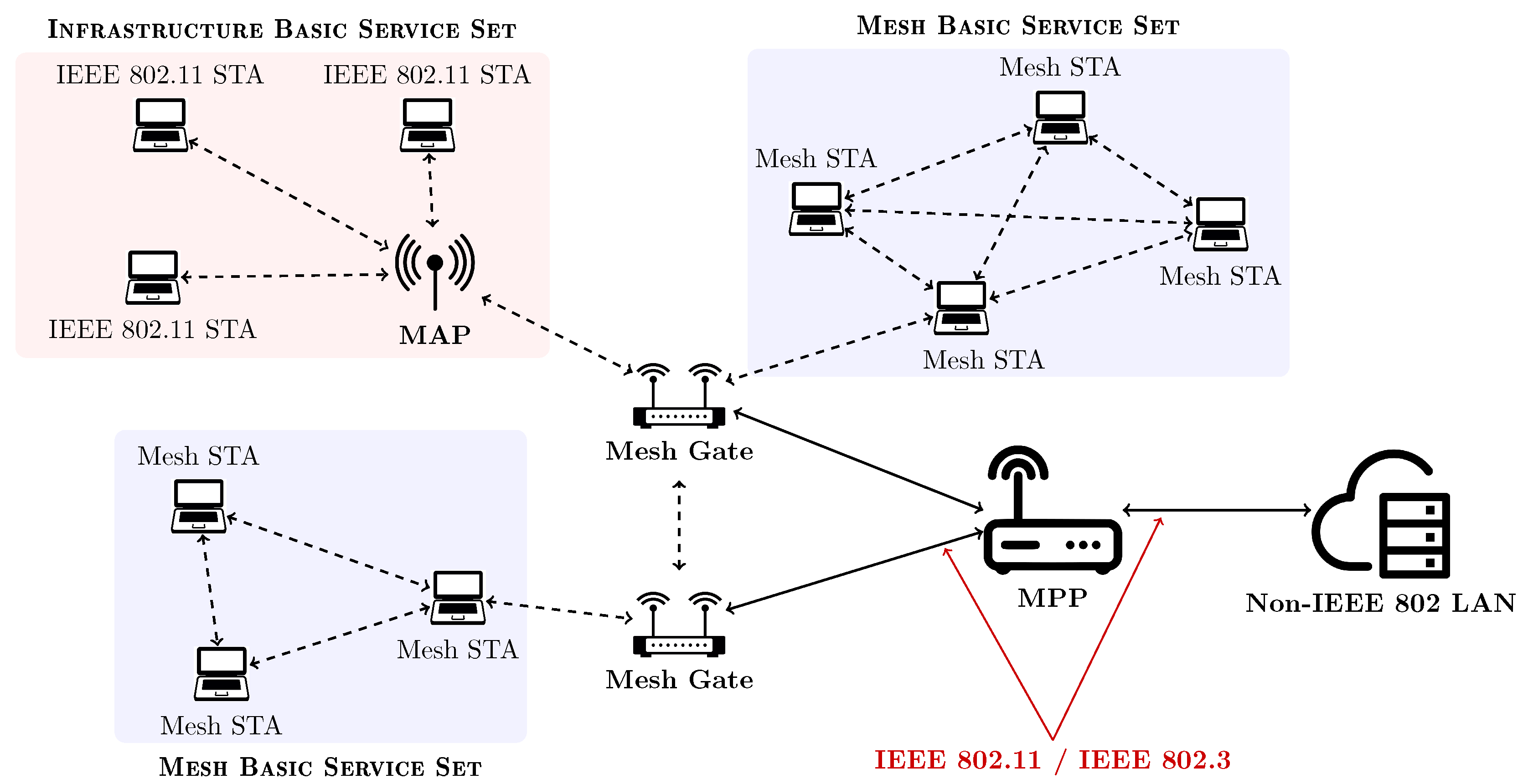
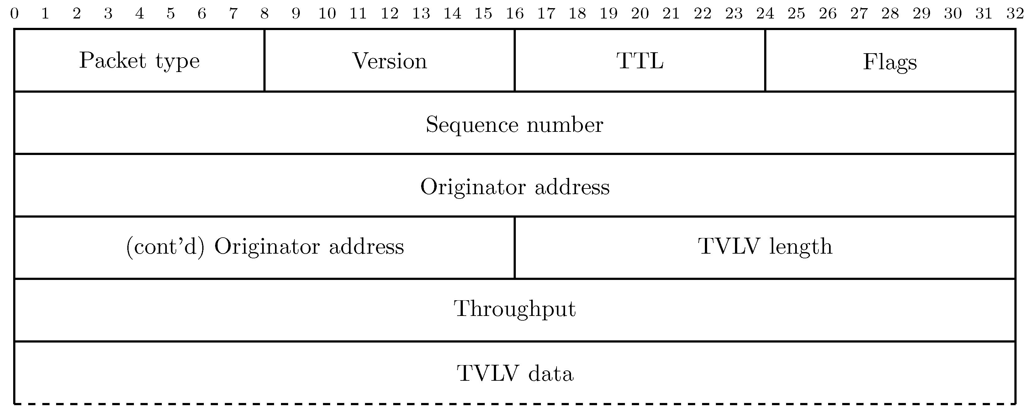
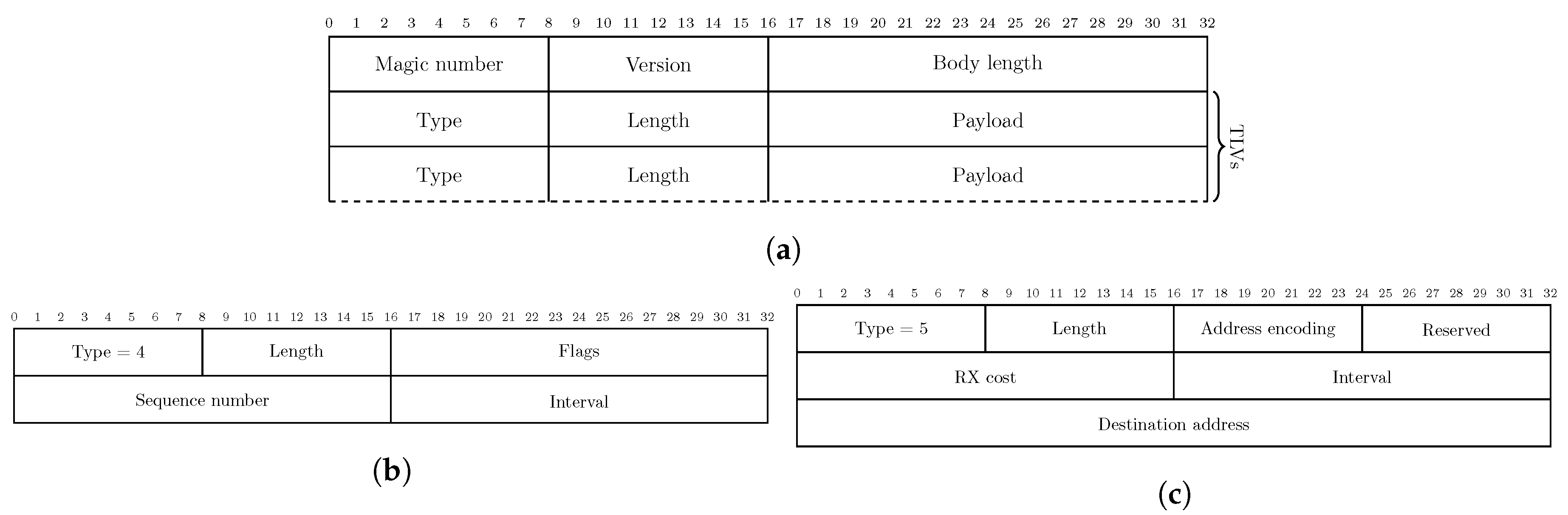
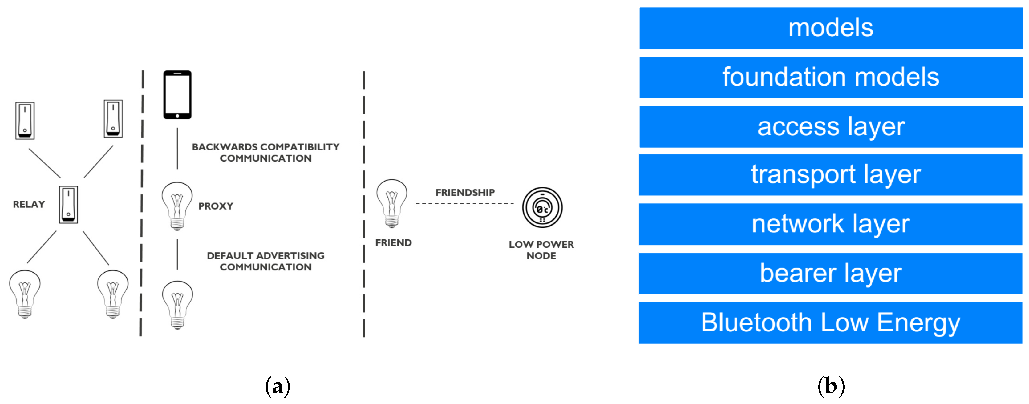
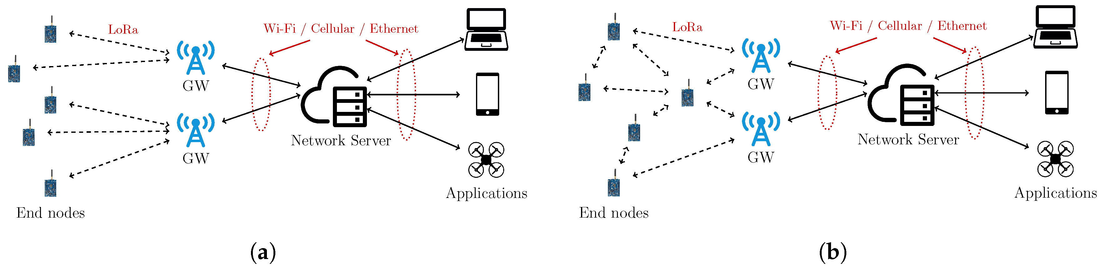
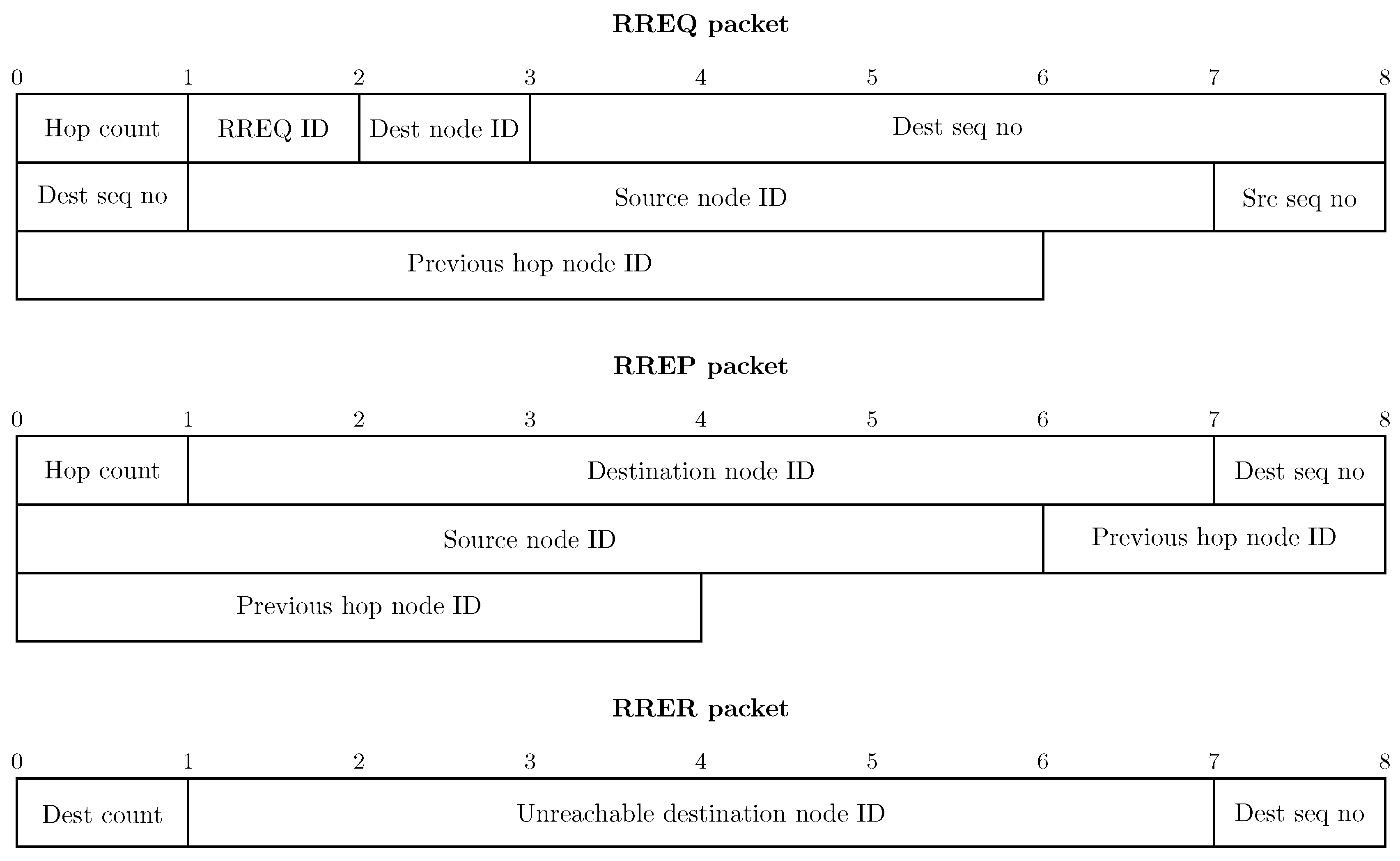
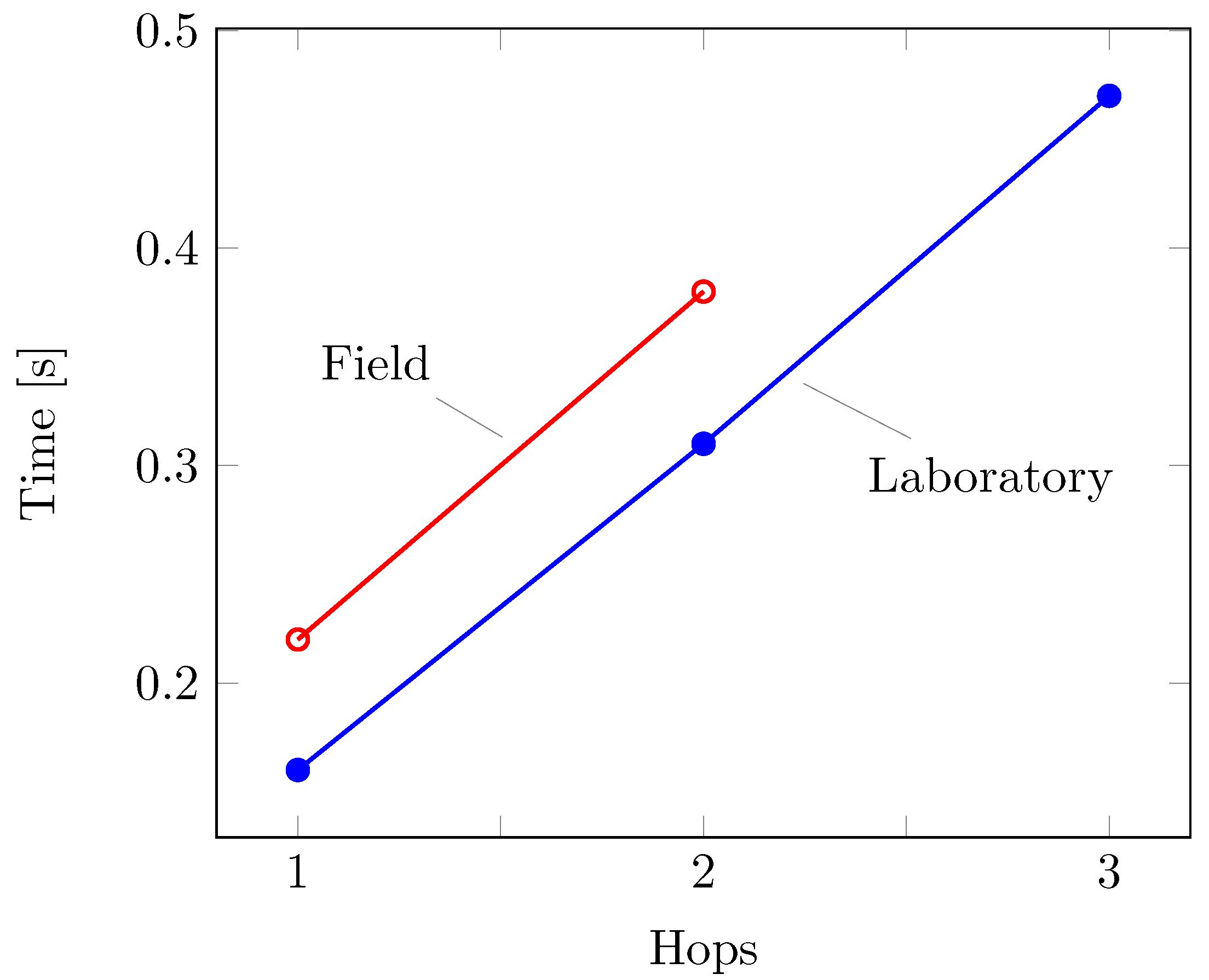
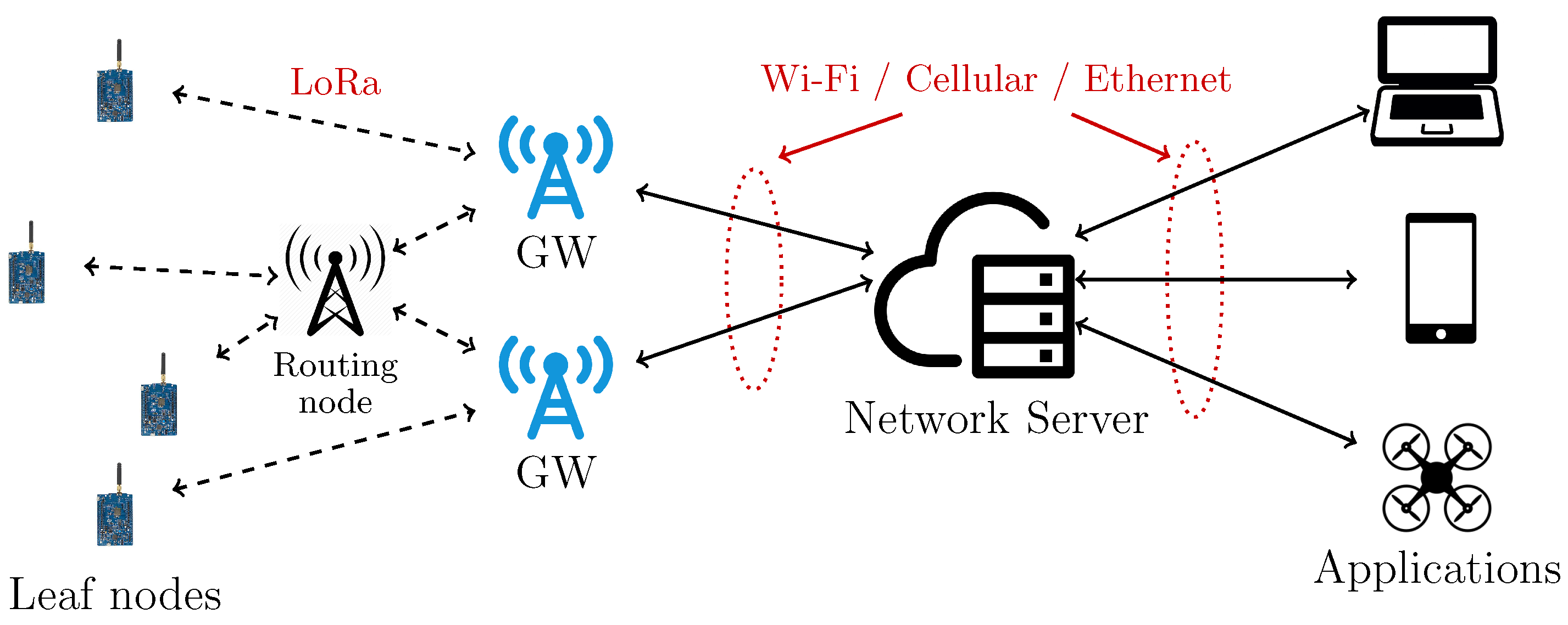
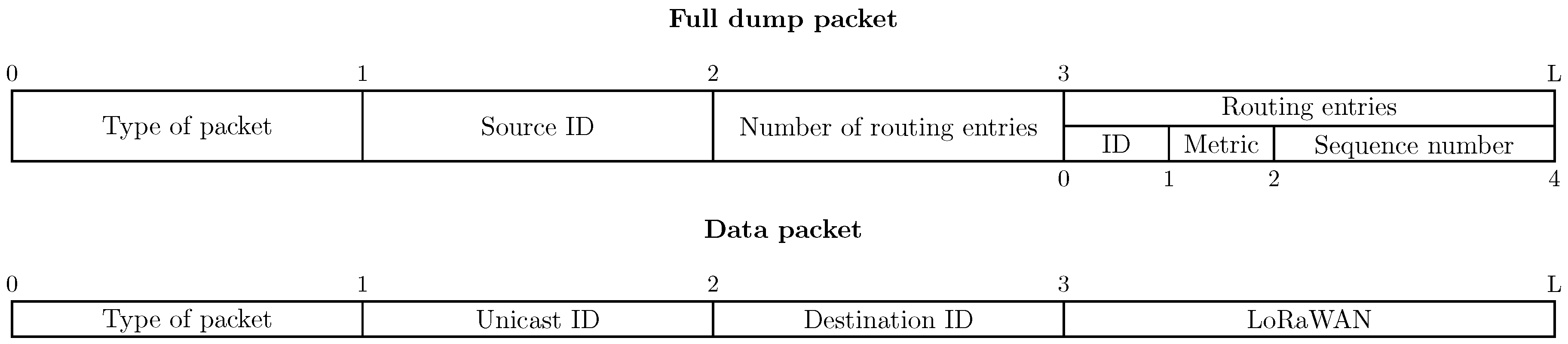
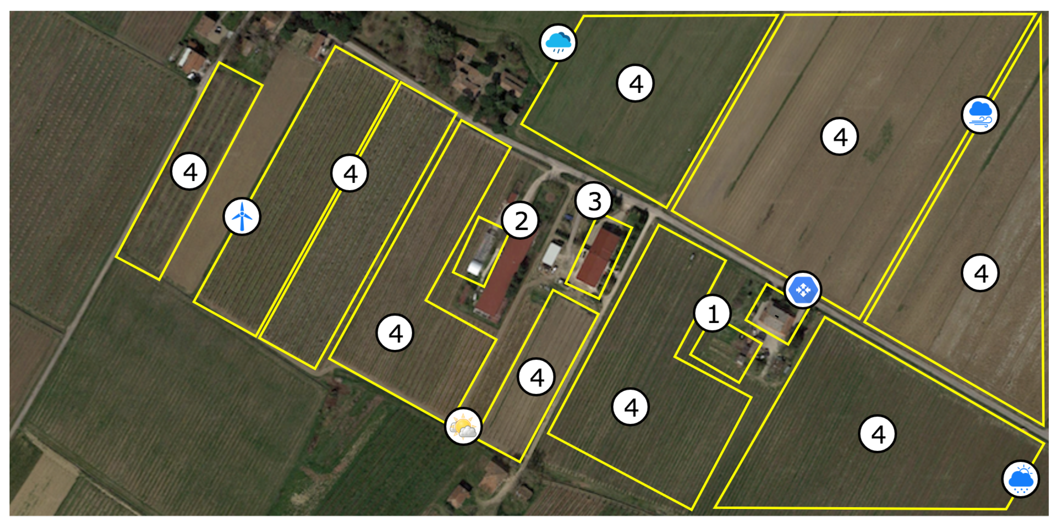
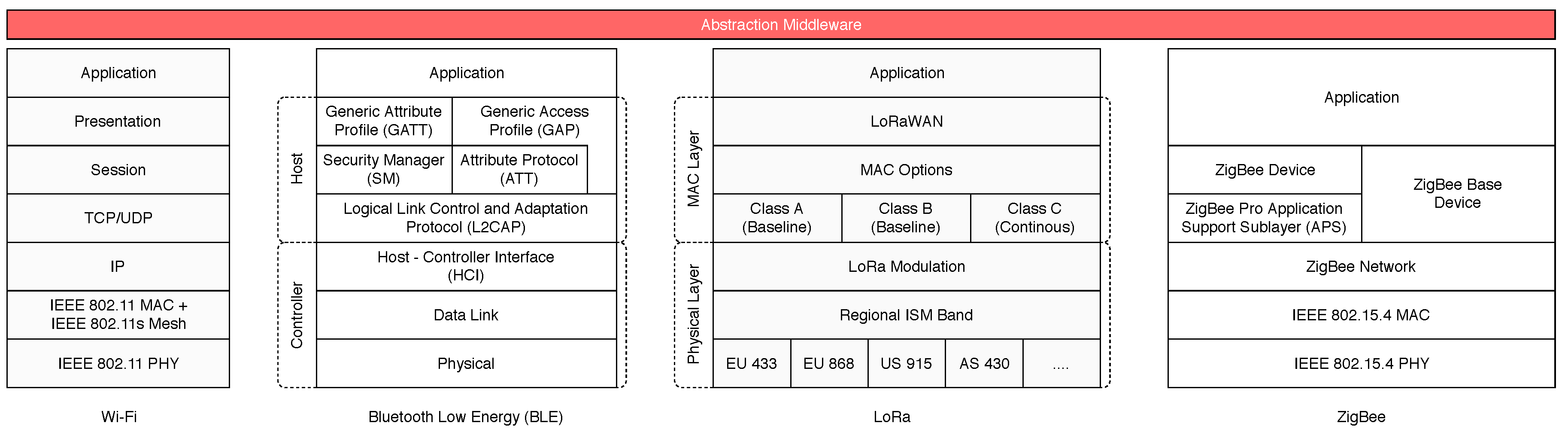
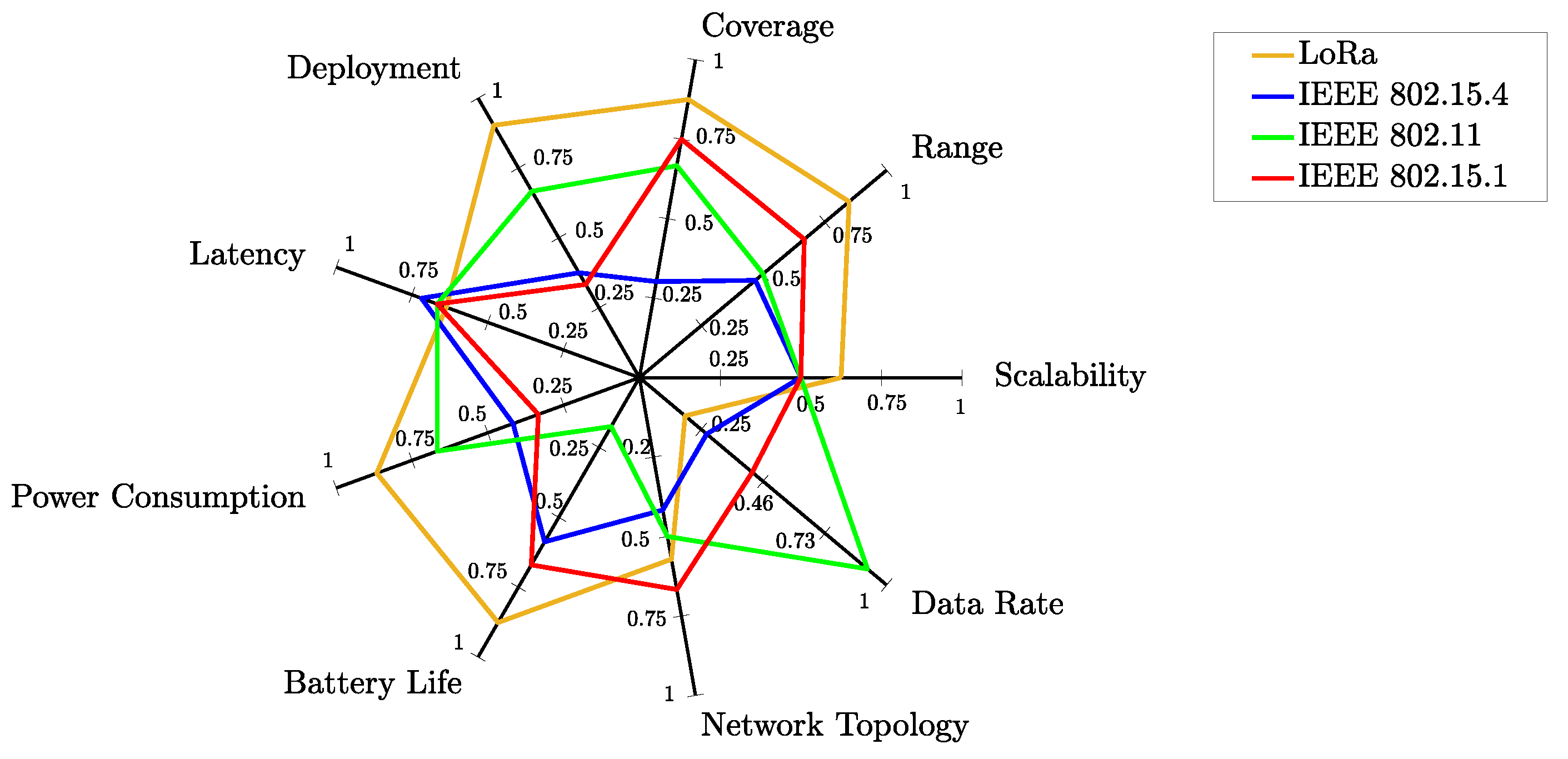
Table A1.
Performance metrics used to evaluate the analyzed WMN protocols.
| LoRa | IEEE 802.15.4 | IEEE 802.11 | IEEE 802.15.1 | |||||||
|---|---|---|---|---|---|---|---|---|---|---|
| [79] | [80] | [81] | [82] | [83] | [82] | [84] | [85] | [86] | [87] | |
| Scalability | 4 | 3.5 | — | — | — | 3 | 3 | 3 | 3 | 3 |
| Range | 5.5 | 5 | 4.5 | 8 | 3.5 | — | — | 3 | 3 | 4 |
| Coverage | 5.5 | 5 | — | 7 | 1 | 3 | 3 | 4 | 4 | 4.5 |
| Deployment | 5.5 | 5.5 | — | 7 | 2 | — | — | 4 | 4 | 2 |
| Latency | 4 | 4 | 5 | 4 | 5.5 | — | — | 4 | 4 | 4 |
| Power Consumption | — | — | 6 | 7 | 4 | — | — | 4 | 4 | 2 |
| Battery Life | 5 | 5.5 | — | — | — | 3.5 | — | 1 | 1 | 4 |
| Network Topology | — | — | 4 | — | — | 2.5 | — | 3 | 3 | 4 |
| Data Rate | — | — | — | 1 | 1.5 | — | — | 5.5 | 5.5 | 2.5 |
| Max Scale () | 6 | 6 | 7 | 8 | 8 | 6 | 6 | 6 | 6 | 6 |
For example, in terms of scalability, from the values in Table A1 one can conclude that: for LoRa the value will be ; for IEEE 802.15.4 the value will be ; for IEEE 802.11 the value will be ; for IEEE 802.15.1 the value will be .
References
- ABI Research. The Internet of Things Will Drive Wireless Connected Devices to 40.9 Billion in 2020. Available online: https://www.abiresearch.com/press/the-internet-of-things-will-drive-wireless-connect/ (accessed on 25 March 2019).
- IHS Markit. Number of Connected IoT Devices Will Surge to 125 Billion by 2030, IHS Markit Says. Available online: https://technology.ihs.com/596542/number-of-connected-iot-devices-will-surge-to-125-billion-by-2030-ihs-markit-says (accessed on 25 March 2019).
- IDTechEx. 5G and Low-Power Wide-Area Networks 2019-2029: Global Forecasts, Technologies, Applications. Available online: https://www.idtechex.com/research/reports/5g-and-low-power-wide-area-networks-2019-2029-global-forecasts-technologies-applications-000614.asp (accessed on 25 March 2019).
- Perkins, C.E.; Bhagwat, P. Highly Dynamic Destination-Sequenced Distance-Vector Routing (DSDV) for Mobile Computers. SIGCOMM Comput. Commun. Rev. 1994, 24, 234–244. [Google Scholar] [CrossRef]
- Johnson, D.; Hu, Y.; Maltz, D. The Dynamic Source Routing Protocol (DSR) for Mobile Ad Hoc Networks for IPv4. RFC 4728, Internet Engineering Task Force. 2007. Available online: https://tools.ietf.org/html/rfc4728 (accessed on 15 April 2019).
- Perkins, C.; Belding-Royer, E.; Das, S. Ad hoc On-Demand Distance Vector (AODV) Routing. RFC 3561, Internet Engineering Task Force. 2003. Available online: https://tools.ietf.org/html/rfc3561 (accessed on 15 April 2019).
- Clausen, T.; Jacquet, P. Optimized Link State Routing Protocol (OLSR). RFC 3626, Internet Engineering Task Force, 2003. Available online: https://tools.ietf.org/html/rfc3626 (accessed on 15 April 2019).
- Institute of Electrical and Electronics Engineers (IEEE). IEEE Standard for Information Technology–Telecommunications and Information Exchange between Systems Local and Metropolitan Area Networks–Specific Requirements—Part 11: Wireless LAN Medium Access Control (MAC) and Physical Layer (PHY) Specifications; IEEE Std 802.11-2016 (Revision of IEEE Std 802.11-2012); IEEE: Piscataway, NJ, USA, 2016; pp. 1–3534. [Google Scholar] [CrossRef]
- Institute of Electrical and Electronics Engineers (IEEE). IEEE Standard for Information Technology–Telecommunications and Information Exchange between Systems–Local and Metropolitan Area Networks–Specific Requirements Part 11: Wireless LAN Medium Access Control (MAC) and Physical Layer (PHY) Specifications Amendment 10: Mesh Networking; IEEE Std 802.11s-2011; IEEE: Piscataway, NJ, USA, 2011; pp. 1–372. [Google Scholar] [CrossRef]
- Hiertz, G.R.; Denteneer, D.; Max, S.; Taori, R.; Cardona, J.; Berlemann, L.; Walke, B. IEEE 802.11s: The WLAN Mesh Standard. IEEE Wirel. Commun. 2010, 17, 104–111. [Google Scholar] [CrossRef]
- Bari, S.M.S.; Anwar, F.; Masud, M.H. Performance study of hybrid Wireless Mesh Protocol (HWMP) for IEEE 802.11s WLAN mesh networks. In Proceedings of the 2012 International Conference on Computer and Communication Engineering (ICCCE), Kuala Lumpur, Malaysia, 3–5 July 2012; pp. 712–716. [Google Scholar] [CrossRef]
- Open-Mesh. Originator Message version 2 (OGMv2). Available online: https://www.open-mesh.org/projects/batman-adv/wiki/OGMv2 (accessed on 25 March 2019).
- Chroboczek, J. The Babel Routing Protocol. RFC 6126, Internet Engineering Task Force. 2011. Available online: https://tools.ietf.org/html/rfc6126 (accessed on 15 April 2019).
- Chroboczek, J. Extension Mechanism for the Babel Routing Protocol. RFC 7557, Internet Engineering Task Force. 2015. Available online: https://tools.ietf.org/html/rfc7557 (accessed on 15 April 2019).
- Savage, D.; Ng, J.; Moore, S.; Slice, D.; Paluch, P.; White, R. Cisco’s Enhanced Interior Gateway Routing Protocol (EIGRP). RFC 7868, Internet Engineering Task Force. 2016. Available online: https://tools.ietf.org/html/rfc7868 (accessed on 15 April 2019).
- Jonglez, B.; Chroboczek, J. Delay-based Metric Extension for the Babel Routing Protocol. Internet-Draft draft-jonglez-babel-rtt-extension-02, Internet Engineering Task Force. 2019. Available online: https://tools.ietf.org/html/draft-jonglez-babel-rtt-extension-02 (accessed on 15 April 2019).
- Chouasne, G.; Chroboczek, J. TOS-Specific Routing in Babel. Internet-Draft draft-chouasne-babel-tos-specific-00, Internet Engineering Task Force. 2017. Available online: https://tools.ietf.org/html/draft-chouasne-babel-tos-specific (accessed on 15 April 2019).
- Boutier, M.; Chroboczek, J. Source-Specific Routing in Babel. Internet-Draft draft-ietf-babel-source-specific-04, Internet Engineering Task Force. 2018. Available online: https://tools.ietf.org/html/draft-ietf-babel-source-specific (accessed on 15 April 2019).
- Chroboczek, J. Applicability of the Babel Routing Protocol. Internet-Draft draft-ietf-babel-applicability-05, Internet Engineering Task Force. 2018. Available online: https://tools.ietf.org/html/draft-ietf-babel-applicability (accessed on 15 April 2019).
- Moy, J. OSPF Version 2. STD 54, Internet Engineering Task Force, 1998. Available online: https://tools.ietf.org/html/rfc2328 (accessed on 15 April 2019).
- Coltun, R.; Ferguson, D.; Moy, J.; Lindem, A. OSPF for IPv6. RFC 5340, Internet Engineering Task Force. 2008. Available online: https://tools.ietf.org/html/rfc5340 (accessed on 15 April 2019).
- Oran, D. OSI IS-IS Intra-domain Routing Protocol. RFC 1142, Internet Engineering Task Force. 1990. Available online: https://tools.ietf.org/html/rfc1142 (accessed on 15 April 2019).
- Ridolfi, M.; Van de Velde, S.; Steendam, H.; De Poorter, E. WiFi ad-hoc mesh network and MAC protocol solution for UWB indoor localization systems. In Proceedings of the 2016 Symposium on Communications and Vehicular Technologies (SCVT), Mons, Belgium, 22 November 2016; pp. 1–6. [Google Scholar] [CrossRef]
- Katila, C.J.; Di Gianni, A.; Buratti, C.; Verdone, R. Routing protocols for video surveillance drones in IEEE 802.11s Wireless Mesh Networks. In Proceedings of the 2017 European Conference on Networks and Communications (EuCNC), Oulu, Finland, 12–15 June 2017; pp. 1–5. [Google Scholar] [CrossRef]
- Zambrano, M.; Esteve, M.; Pérez, I.; Carvajal, F.; Zambrano, A.M. Situation awareness in the large forest fires response. A solution based on wireless mesh networks. In Proceedings of the 2017 IEEE 9th Latin-American Conference on Communications (LATINCOM), Guatemala City, Guatemala, 8–10 November 2017; pp. 1–6. [Google Scholar] [CrossRef]
- Muhendra, R.; Arzi, Y.H. Development of street lights controller using wifi mesh network. In Proceedings of the 2017 International Conference on Smart Cities, Automation Intelligent Computing Systems (ICON-SONICS), Yogyakarta, Indonesia, 8–10 November 2017; pp. 105–109. [Google Scholar] [CrossRef]
- Saputro, N.; Akkaya, K.; Uluagac, S. Supporting Seamless Connectivity in Drone-assisted Intelligent Transportation Systems. In Proceedings of the 2018 IEEE 43rd Conference on Local Computer Networks Workshops (LCN Workshops), Chicago, IL, USA, 1–4 October 2018; pp. 110–116. [Google Scholar] [CrossRef]
- Menouar, H.; Guvenc, I.; Akkaya, K.; Uluagac, A.S.; Kadri, A.; Tuncer, A. UAV-enabled intelligent transportation systems for the smart city: Applications and challenges. IEEE Commun. Mag. 2017, 55, 22–28. [Google Scholar] [CrossRef]
- Decristofaro, M.A.; Lansdowne, C.A.; Schlesinger, A.M. Heterogeneous Wireless Mesh Network Technology Evaluation for Space Proximity and Surface Applications. In Proceedings of the 13th SpaceOps 2014, Pasadena, CA, USA, 5–9 May 2014. [Google Scholar] [CrossRef]
- Kim, H.; Lee, J.; Jang, J.W. BLEmesh: A Wireless Mesh Network Protocol for Bluetooth Low Energy Devices. In Proceedings of the 2015 3rd International Conference on Future Internet of Things and Cloud, Rome, Italy, 24–26 August 2015; pp. 558–563. [Google Scholar] [CrossRef]
- Sirur, S.; Juturu, P.; Gupta, H.P.; Serikar, P.R.; Reddy, Y.K.; Barak, S.; Kim, B. A mesh network for mobile devices using Bluetooth low energy. In Proceedings of the 2015 IEEE SENSORS, Busan, South Korea, 1–4 November 2015; pp. 1–4. [Google Scholar] [CrossRef]
- Zenker, P.; Krug, S.; Binhack, M.; Seitz, J. Evaluation of BLE Mesh capabilities: A case study based on CSRMesh. In Proceedings of the 2016 Eighth International Conference on Ubiquitous and Future Networks (ICUFN), Vienna, Austria, 5–8 July 2016; pp. 790–795. [Google Scholar] [CrossRef]
- Prasetyo, J.A.; Yushev, A.; Sikora, A. Investigations on the performance of bluetooth enabled mesh networking. In Proceedings of the 2016 3rd International Symposium on Wireless Systems within the Conferences on Intelligent Data Acquisition and Advanced Computing Systems (IDAACS-SWS), Offenburg, Germany, 26–27 September 2016; pp. 56–61. [Google Scholar] [CrossRef]
- Bluetooth, S. Mesh Profile Specification: 1.0; Bluetooth Special Interest Group: Kirkland, WA, USA, 2017. [Google Scholar]
- Apple iBeacon. 2013. Available online: https://developer.apple.com/ibeacon/ (accessed on 15 April 2019).
- Baert, M.; Rossey, J.; Shahid, A.; Hoebeke, J. The Bluetooth mesh standard: An overview and experimental evaluation. Sensors 2018, 18, 2409. [Google Scholar] [CrossRef] [PubMed]
- Gomez, C.; Darroudi, S.; Savolainen, T.; Spoerk, M. IPv6 Mesh over BLUETOOTH(R) Low Energy using IPSP. Internet-Draft draft-ietf-6lo-blemesh-03, Internet Engineering Task Force. 2018. Available online: https://tools.ietf.org/html/draft-ietf-6lo-blemesh (accessed on 15 April 2019).
- Nieminen, J.; Savolainen, T.; Isomaki, M.; Patil, B.; Shelby, Z.; Gomez, C. IPv6 over BLUETOOTH(R) Low Energy. RFC 7668, Internet Engineering Task Force. 2015. Available online: https://tools.ietf.org/html/rfc7668 (accessed on 15 April 2019).
- Group, B.S.I. Internet Protocol Support Profile V 1.0.0; Technical Report; Bluetooth Special Interest Group: Kirkland, WA, USA, 2014. [Google Scholar]
- Silva, H.C.; Margi, C.B. Energy and performance costs evaluation for BLE mesh links. In Proceedings of the Brazilian Symposium on Computer Networks and Distributed Systems (SBRC), Campos do Jordao, Brazil, 6–10 May 2018; SBC: Porto Alegre, Brazil, 2018. [Google Scholar]
- Leonardi, L.; Patti, G.; Bello, L.L. Multi-hop Real-time Communications over Bluetooth Low Energy Industrial Wireless Mesh Networks. IEEE Access 2018, 6, 26505–26519. [Google Scholar] [CrossRef]
- Snekvik, T. nRF OpenMesh; Technical Report; Norwegian University of Science and Technology: Trondheim, Norway, 2015. [Google Scholar]
- Levis, P.; Clausen, T.; Hui, J.; Gnawali, O.; Ko, J. The Trickle Algorithm. RFC 6206, Internet Engineering Task Force. 2011. Available online: https://tools.ietf.org/html/rfc6206 (accessed on 15 April 2019).
- Murillo, Y.; Reynders, B.; Chiumento, A.; Malik, S.; Crombez, P.; Pollin, S. Bluetooth now or low energy: Should BLE mesh become a flooding or connection oriented network? In Proceedings of the 2017 IEEE 28th Annual International Symposium on Personal, Indoor, and Mobile Radio Communications (PIMRC), Montreal, QC, Canada, 8–13 October 2017; pp. 1–6. [Google Scholar] [CrossRef]
- Darroudi, S.; Gomez, C. Bluetooth low energy mesh networks: A survey. Sensors 2017, 17, 1467. [Google Scholar] [CrossRef] [PubMed]
- Trogh, J.; Plets, D.; Martens, L.; Joseph, W. Bluetooth low energy based location tracking for livestock monitoring. In Proceedings of the 8th European Conference on Precision Livestock Farming, Nantes, France, 12–14 September 2017; pp. 469–475. [Google Scholar]
- Lin, Y.W.; Lin, C.Y. An Interactive Real-Time Locating System Based on Bluetooth Low-Energy Beacon Network. Sensors 2018, 18, 1637. [Google Scholar] [CrossRef]
- Veiga, A.; Abbas, C. Proposal and Application of Bluetooth Mesh Profile for Smart Cities’ Services. Smart Cities 2019, 2, 1–19. [Google Scholar] [CrossRef]
- Zhang, B.; Wang, Y.; Wei, L.; Jin, Q.; Vasilakos, A.V. BLE mesh: A practical mesh networking development framework for public safety communications. Tsinghua Sci. Technol. 2018, 23, 333–346. [Google Scholar] [CrossRef]
- Fraga-Lamas, P.; Lopez-Iturri, P.; Celaya-Echarri, M.; Blanco-Novoa, O.; Azpilicueta, L.; Varela-Barbeito, J.; Falcone, F.; Fernández-Caramés, T.M. Design and Validation of a Bluetooth 5 Fog Computing Based Industrial CPS Architecture for Intelligent Industry 4.0 Shipyard Workshops. arXiv 2019, arXiv:1903.00713. [Google Scholar]
- Danebjer, F.; Schreiter, C. Bluetooth Mesh Interoperability Analysis; Student Paper; Lund University: Lund, Sweden, 2017. [Google Scholar]
- Zigbee PRO Mesh Protocol. Available online: https://www.zigbee.org/zigbee-for-developers/zigbee-pro/ (accessed on 22 December 2018).
- Zigbee 3.0 mesh protocol. Available online: https://www.zigbee.org/zigbee-for-developers/zigbee-3-0/ (accessed on 22 December 2018).
- ZigBee Specification—Document 053474r20. Available online: https://www.zigbee.org/download/standard-zigbee-pro-specification-2/ (accessed on 22 December 2018).
- Belli, L.; Cirani, S.; Davoli, L.; Gorrieri, A.; Mancin, M.; Picone, M.; Ferrari, G. Design and Deployment of an IoT Application-Oriented Testbed. Computer 2015, 48, 32–40. [Google Scholar] [CrossRef]
- Davoli, L.; Belli, L.; Cilfone, A.; Ferrari, G. Integration of Wi-Fi mobile nodes in a Web of Things Testbed. ICT Express 2016, 2, 95–99. [Google Scholar] [CrossRef]
- Cirani, S.; Davoli, L.; Ferrari, G.; Léone, R.; Medagliani, P.; Picone, M.; Veltri, L. A Scalable and Self-Configuring Architecture for Service Discovery in the Internet of Things. IEEE Internet Things J. 2014, 1, 508–521. [Google Scholar] [CrossRef]
- Davoli, L.; Antonini, M.; Ferrari, G. DiRPL: A RPL-Based Resource and Service Discovery Algorithm for 6LoWPANs. Appl. Sci. 2018, 9. [Google Scholar] [CrossRef]
- ZigBee PRO Stack—JN-UG-3048. Available online: https://www.nxp.com/docs/en/user-guide/JN-UG-3048.pdf (accessed on 22 December 2018).
- Salsano, S.; Veltri, L.; Davoli, L.; Ventre, P.L.; Siracusano, G. PMSR—Poor Man’s Segment Routing, a minimalistic approach to Segment Routing and a Traffic Engineering use case. In Proceedings of the NOMS 2016—2016 IEEE/IFIP Network Operations and Management Symposium, Istanbul, Turkey, 25–29 April 2016; pp. 598–604. [Google Scholar] [CrossRef]
- Thread—Official Website. Available online: https://www.threadgroup.org/BUILT-FOR-IOT/Home (accessed on 20 December 2018).
- Rzepecki, W.; Iwanecki, L.; Ryba, P. IEEE 802.15.4 Thread Mesh Network—Data Transmission in Harsh Environment. In Proceedings of the 2018 6th International Conference on Future Internet of Things and Cloud Workshops (FiCloudW), Barcelona, Spain, 6–8 August 2018; pp. 42–47. [Google Scholar] [CrossRef]
- Unwala, I.; Taqvi, Z.; Lu, J. Thread: An IoT Protocol. In Proceedings of the 2018 IEEE Green Technologies Conference (GreenTech), Austin, TX, USA, 4–6 April 2018; pp. 161–167. [Google Scholar] [CrossRef]
- OpenWeave: A Secure and Reliable Communications Backbone for the Connected Home. Available online: https://openweave.io/ (accessed on 20 December 2018).
- OMA LightweightM2M V1.0 Overview. Available online: http://www.openmobilealliance.org/wp/Overviews/lightweightm2moverview.html (accessed on 20 December 2018).
- Rao, S.; Chendanda, D.; Deshpande, C.; Lakkundi, V. Implementing LWM2M in constrained IoT devices. In Proceedings of the 2015 IEEE Conference on Wireless Sensors (ICWiSe), Melaka, Malaysia, 24–26 August 2015; pp. 52–57. [Google Scholar] [CrossRef]
- Dotdor—Official Website. Available online: https://www.zigbee.org/zigbee-for-developers/dotdot/ (accessed on 20 December 2018).
- OCF Specifications. Available online: https://openconnectivity.org/developer/specifications (accessed on 20 December 2018).
- Thread: IPv6-Based Mesh Networking for the Smart Home and Building Automation. Available online: https://www.nordicsemi.com/Products/Low-power-short-range-wireless/Thread (accessed on 22 December 2018).
- Thread: Connecting Devices Where We Live & Work. Available online: https://www.threadgroup.org/BUILT-FOR-IOT/Commercial (accessed on 22 December 2018).
- Atmel Lightweight Mesh. Available online: https://www.microchip.com/developmenttools/ProductDetails/AtmelLightweightMesh (accessed on 22 December 2018).
- Atmel Lightweight Mesh—AVR2130: Lightweight Mesh Developer Guide. Available online: https://www.microchip.com/wwwAppNotes/AppNotes.aspx?appnote=en591088 (accessed on 22 December 2018).
- Cervenka, V.; Mraz, L.; Komosny, D. Comprehensive Performance Analysis of Lightweight Mesh and Its Comparison with ZigBee Pro Technology. Wirel. Pers. Commun. 2014, 78, 1527–1538. [Google Scholar] [CrossRef]
- Bor, M.; Vidler, J.; Roedig, U. LoRa for the Internet of Things. In Proceedings of the 2016 International Conference on Embedded Wireless Systems and Networks, EWSN ’16, Graz, Austria, 15–17 February 2016; pp. 361–366. [Google Scholar]
- Lundell, D.; Hedberg, A.; Nyberg, C.; Fitzgerald, E. A Routing Protocol for LoRA Mesh Networks. In Proceedings of the 2018 IEEE 19th International Symposium on “A World of Wireless, Mobile and Multimedia Networks” (WoWMoM), Chania, Greece, 12–15 June 2018; pp. 14–19. [Google Scholar] [CrossRef]
- Lee, H.; Ke, K. Monitoring of Large-Area IoT Sensors Using a LoRa Wireless Mesh Network System: Design and Evaluation. IEEE Trans. Instrum. Meas. 2018, 67, 2177–2187. [Google Scholar] [CrossRef]
- Dias, J.; Grilo, A. LoRaWAN multi-hop uplink extension. Procedia Comput. Sci. 2018, 130, 424–431. [Google Scholar] [CrossRef]
- Davoli, L.; Belli, L.; Cilfone, A.; Ferrari, G. From Micro to Macro IoT: Challenges and Solutions in the Integration of IEEE 802.15.4/802.11 and Sub-GHz Technologies. IEEE Internet Things J. 2018, 5, 784–793. [Google Scholar] [CrossRef]
- Connectivity Now and Beyond; Exploring Cat-M1, NB-IoT, and LPWAN Connections. Available online: https://ubidots.com/blog/exploring-cat-m1-nb-iot-lpwan-connections (accessed on 27 March 2019).
- Mekki, K.; Bajic, E.; Chaxel, F.; Meyer, F. A comparative study of LPWAN technologies for large-scale IoT deployment. ICT Express 2019, 5, 1–7. [Google Scholar] [CrossRef]
- Leti Boasts of LoRa, NB-IoT-Beating LPWA-CB Tests. Available online: https://abopen.com/news/leti-boasts-of-lora-nb-iot-beating-lpwan-tests (accessed on 27 March 2019).
- Wireless Standards for IoT: WiFi, BLE, SigFox, NB-IoT and LoRa. Available online: http://wireless.ictp.it/school2017/Slides/IoTWirelessStandards.pdf (accessed on 27 March 2019).
- Diez, M. Secure Position Data Transmission for Object Tracking using LoRaWAN. Available online: https://files.ifi.uzh.ch/CSG/staff/schmitt/Extern/Theses/Matthias_Diez_MA.pdf (accessed on 27 March 2019).
- Petrosky, E.E.; Michaels, A.J.; Ridge, D.B. Network Scalability Comparison of IEEE 802.15.4 and Receiver-Assigned CDMA. IEEE Internet Things J. 2019, 1. [Google Scholar] [CrossRef]
- Casilari, E.; Florez-Lara, A.; Cano-García, J.M. Analysis of the scalability of hierarchical IEEE 802.15.4/Zigbee networks. In Proceedings of the 3rd International ICST Conference on Scalable Information Systems, INFOSCALE 2008, Vico Equense, Italy, 4–6 June 2008; p. 3. [Google Scholar] [CrossRef]
- The Role of Wi-Fi & Unlicensed Technologies in 5G. Available online: https://www.wballiance.com/the-role-of-wi-fi-unlicensed-technologies-in-5g (accessed on 27 March 2019).
- Pothuganti, K.; Chitneni, A. A Comparative Study of Wireless Protocols: Bluetooth, UWB, ZigBee, and Wi-Fi. Adv. Electron. Electr. Eng. 2014, 4, 655–662. [Google Scholar]
- MEMS and Wireless Options: User Localization in Cellular Phones. Available online: https://www.gpsworld.com/mems-and-wireless-options-user-localization-in-cellular-phones (accessed on 27 March 2019).
- Pascual, M.D.G. Indoor Location Systems Based on ZigBee Networks. Bachelor’s Thesis, Mikkeli University of Applied Sciences, Mikkeli, Finland, 2012. [Google Scholar] [CrossRef]
- Morin, E.; Maman, M.; Guizzetti, R.; Duda, A. Comparison of the Device Lifetime in Wireless Networks for the Internet of Things. IEEE Access 2017, 5, 7097–7114. [Google Scholar] [CrossRef]
Figure 1.
Architecture of MBSS containing mesh STAs, APs and portals as designed in IEEE 802.11s standard [8].
Figure 1.
Architecture of MBSS containing mesh STAs, APs and portals as designed in IEEE 802.11s standard [8].

Figure 2.
OriGinator Message version 2 (OGMv2) packet format.

Figure 3.
Main Babel packets. (a) Babel packet; (b) Hello TLV of Babel protocol.; (c) IHU TLV of Babel protocol.
Figure 3.
Main Babel packets. (a) Babel packet; (b) Hello TLV of Babel protocol.; (c) IHU TLV of Babel protocol.

Figure 4.
Examples of optional features within the Bluetooth Mesh standard and protocol stack. (a) Examples of optional features within the Bluetooth Mesh standard; (b) BLE protocol stack.
Figure 4.
Examples of optional features within the Bluetooth Mesh standard and protocol stack. (a) Examples of optional features within the Bluetooth Mesh standard; (b) BLE protocol stack.

Figure 5.
Protocol stack and network architecture representation of an infrastructure handled with Thread protocol. (a) Thread networking protocol stack [69]; (b) Thread network architecture example [70].

Figure 6.
General LWMesh frame format.

Figure 7.
LoRaWAN network topology. (a) Star of star topology in LoRaWAN network; (b) Mesh topology in LoRaWAN network.
Figure 7.
LoRaWAN network topology. (a) Star of star topology in LoRaWAN network; (b) Mesh topology in LoRaWAN network.

Figure 8.
Route REQuest (RREQ), Route REPly (RREP) and Route ERRor (RERR) packet format.

Figure 9.
Measured construction time [75].
Figure 9.
Measured construction time [75].

Figure 10.
Packet Delivery Ratio [76].
Figure 10.
Packet Delivery Ratio [76].

Figure 11.
LoRa-based network with intermediate relay.

Figure 12.
Full dump and data packet structure.

Figure 13.
General view of the target farm considered in a smart agriculture use case, composed by the farmer’s gateway (blue icon), an agricultural vegetable garden (marker 1), a botany greenhouse (marker 2), a livestock stable (marker 3), various fields (markers 4), and several weather monitoring stations (weather icons).

Figure 14.
General view of city concerning different services, each of them handled by a particular module.
Figure 14.
General view of city concerning different services, each of them handled by a particular module.

Figure 15.
Mesh protocols stacks and abstraction middleware for traffic harmonization.

Figure 16.
Comparison among the analyzed communication protocols, based on data rate and transmission range. Minimum and maximum values (with average) are indicated for each performance metric.
Figure 16.
Comparison among the analyzed communication protocols, based on data rate and transmission range. Minimum and maximum values (with average) are indicated for each performance metric.

Figure 17.
Comparative performance analysis, with 9 relevant metrics, of 4 wireless mesh technologies.
Figure 17.
Comparative performance analysis, with 9 relevant metrics, of 4 wireless mesh technologies.

© 2019 by the authors. Licensee MDPI, Basel, Switzerland. This article is an open access article distributed under the terms and conditions of the Creative Commons Attribution (CC BY) license (http://creativecommons.org/licenses/by/4.0/).
Share and Cite
MDPI and ACS Style
Cilfone, A.; Davoli, L.; Belli, L.; Ferrari, G. Wireless Mesh Networking: An IoT-Oriented Perspective Survey on Relevant Technologies. Future Internet 2019, 11, 99. https://doi.org/10.3390/fi11040099
AMA Style
Cilfone A, Davoli L, Belli L, Ferrari G. Wireless Mesh Networking: An IoT-Oriented Perspective Survey on Relevant Technologies. Future Internet. 2019; 11(4):99. https://doi.org/10.3390/fi11040099
Chicago/Turabian StyleCilfone, Antonio, Luca Davoli, Laura Belli, and Gianluigi Ferrari. 2019. "Wireless Mesh Networking: An IoT-Oriented Perspective Survey on Relevant Technologies" Future Internet 11, no. 4: 99. https://doi.org/10.3390/fi11040099
Note that from the first issue of 2016, this journal uses article numbers instead of page numbers. See further details here.