Manufacturing-Induced Imperfections in Composite Parts Manufactured via Automated Fiber Placement


German Aerospace Center (DLR e.V.), Institute of Composite Structures and Adaptive Systems, Department of Structural Mechanics, Lilienthalplatz 7, 38108 Braunschweig, Germany
*
Author to whom correspondence should be addressed.
J. Compos. Sci. 2019, 3(2), 56; https://doi.org/10.3390/jcs3020056
Submission received: 28 March 2019
/
Revised: 26 April 2019
/
Accepted: 20 May 2019
/
Published: 2 June 2019
Abstract
:The automated fiber placement process (AFP) enables the manufacturing of large and geometrical complex fiber composite structures with high quality at low cycle times. Although the AFP process is highly accurate and reproducible, manufacturing induced imperfections in the produced composite structure occur. This review summarizes and classifies typical AFP-related manufacturing defects. Several methodologies for evaluating the effects of such manufacturing defects from the literature are reviewed. This review paper presents recent scientific contributions and discusses proposed experimental and simulation-based methodologies. Among the identified ten defect classes, gaps and overlaps are predominant. This paper focuses then on methods for modelling and assessing gaps and overlaps. The state of the art in modelling gaps and overlaps and assessing their influence on mechanical properties is presented. Finally, research gaps and remaining issues are identified.
1. Introduction
Fiber-reinforced plastics are superior to metals in terms of weight-specific stiffness and strength. In particular, the aerospace sector tries to exploit these advantages in order to reduce the structural weight and finally to minimize the fuel consumption leading to operational cost reduction. To benefit from the advantages of fiber-reinforced plastics, the manufacturing costs (composed of costs for the material as well as machine investment and operation) may not exceed the operational costs saved. In consequence the original equipment manufacturer (OEM) face the challenge how to reduce the manufacturing costs, while at the same time comply with part quality requirements.
Regarding this challenge, a considerable efficiency increase is possible along the entire development chain of fiber composite components. Manufacturers are currently struggling to fully exploit the mechanical capabilities of composite structures due to conservative design and high quality requirements during the production and assembly process [1,2]. Comprehensive technical databases for managing manufacturing induced imperfections and tolerances are missing [1] (p. 150). So far, issues emerging from manufacturing uncertainties (e.g., imperfections and tolerances) have not received sufficient attention in the development and certification of composite components.
In order to ensure the process is robust, a considerable effort is spent. The aerospace sector annually invests roughly 350 million Euro [1] (S. 137) solely for certification purposes of materials and components made from fiber-reinforced plastics. Besides, by means of manufacturing trials based on the trial and error principle, a robust process window with associated optimal process parameters is identified for each component. In many cases, this results in high tolerance requirements, as a result of the process sensitivity against fluctuations in the process parameters.
Currently, the manufacturers of composite structures react to uncertainties emerging from manufacturing with high safety margins, so-called knock-down factors (KDFs) for the mechanical properties [1,2,3], and elevated rejection rates. During process monitoring and component quality testing, strict compliance with the demanding structural and tolerance requirements often leads to unscheduled idle times and downtime due to rework and repairs [1] (S. 150). In relation to the cycle time of an AFP machine, the time required for manual quality assurance and rework is currently up to 41% (cf. Figure 1). Accordingly, the full potential of automated series production is not yet realized. As a result the manufacturing costs rise due to non-value added processes [4]. Consequently, fiber-reinforced plastics partially lose their competitiveness compared to metallic materials.
For several aerospace applications, manual process steps still dominate the manufacturing of fiber-reinforced structures [7]. The automation of these process steps is an integral milestone on the way to a robust, fast, affordable and reliable (quality assurance) manufacturing process [8]. Due to their robustness and speed as well as repeatability the Automated Tape Laying (ATL) and the Automated Fiber Placement (AFP) technology is ideally suited to manufacture large and geometrical complex structures [9,10]. Both enable creating layups automatically within a single process step including ply cutting, deposition and compaction [11]. The aerospace industry already exploits these advantages when manufacturing various aircraft components such as the empennage, wings and fuselage [7,12,13,14]. Table 1 gives an overview for which components and aircraft the OEMs apply ATL and AFP.
Switching to an automated manufacturing process is an essential step towards enhancing productivity and reproducibility of composite parts [15,16]. Irrespective of the repeatability and precision of the automated process, the actual manufactured part (as-built) may deviate from the nominal part (as-designed/as-to-be-build) depending on manufacturing constraints and the part complexity. Variations in the orientation and positioning of the fiber material already emerge during the deposition on simple, non-curved surfaces [17]. Manufacturing constraints [11] and uncertainties, such as tolerances and material variability, further reduce the benefits of automation [7,18].
By fully exploiting the potential of automated fiber deposition, manufacturing induced imperfections such as gaps, overlaps, twists, fiber waviness and fiber wrinkling are inevitable. A profound knowledge of the structural mechanical influence resulting from these imperfections is of vital importance for the efficiency of composite structures and the associated manufacturing process. Lukaszewicz et al. [16] emphasize that there is research needed with respect to the effects of manufacturing imperfections. In particular further investigations are needed regarding their effect on the laminate mechanical properties.
Against this background, the aims of this review article are to provide an overview of the manufacturing induced imperfections that are relevant for AFP and to categorize them. Furthermore, this publication derives from the literature to what extent the origin and consequences of AFP-induced imperfections are understood. Accordingly, the text contains two substantial parts dedicated to the identification and analysis of imperfections.
Since the 1990s, research activities with respect to the automated manufacturing of composite structures continually intensifies. Despite the increasing activities Lozano et al. [23] raise awareness again concerning the limited scope of the research work so far like Lukaszewicz et al. [16] already stated several years before. There are gaps in research, particularly in the field of structures with unconventional laminates, capable of exploiting the full potential of fibre composites. Unconventional laminates are characterized by locally varying mechanical properties (often referred to as Variable Stiffness Composites—VSC or Variable Stiffness Composite Laminates—VSCL). In their current work Lozano et al. [24] provide a comprehensive overview of the state of the art in research on the design and manufacturing of such structures.
A network analysis was performed as illustrated in Figure 2 to identify author networks scientifically collaborating in the field of ATL, AFP and VSCL structures since the 1990s. In Figure 2 circles symbolize individual authors. The size and gray scale of a circle represents the number of publications of the respective author. Lines of different size and gray scale show the participation as co-author. The network analysis reveals that there are many independent and stand-alone studies among the 171 investigated scientific contributions. Three researcher networks are emerging. They significantly contribute in the field of ATL, AFP and VSCL structures. In this field of research they may be considered foremost. Aspects not yet published by these researcher networks are likely to be gaps in the literature and research. Figure 3 highlights the identified researcher networks, pointing out the most contributing representatives.
Not all 171 publications included in the network analysis are mentioned in this review paper. This review lists only those that deal with either AFP-induced imperfections or the modeling and evaluation of AFP structures.
2. Manufacturing Induced Imperfections
The ability of FW to output individual fiber bundles combined with the ability of ATL systems to stop, cut and restart individual fiber bundles is what makes AFP so versatile [8,19,25]. The AFP technology thus combines the advantages of winding and tape laying technology. However, an ATL system is capable of achieving higher material deposition rates and produces therefore more cost-effectively. AFP in turn enables producing complex curved structures and to steer fibers [19,20]. Fiber steering means the continuous variation of the fiber placement path, which enables the production of VSCL structures [20,25,26].
Current AFP systems work with up to 32 so-called tows either made from dry or pre-impregnated fiber material [25] in widths of 3.2 mm, 6.4 mm or 12.7 mm [20,27]. The geometrical complexity and the steering radius determine the actual course width [16], which is defined by the number of tows placed onto the surface. It corresponds to a multiple of a tow width. The controlled deposition of fibers on complex geometries, even using fiber steering is challenging for following reasons [28,29]:
- The layup quality significantly depends on the amount and size of these imperfections [31].
- Primary imperfections are a direct result of deviations during manufacturing (e.g., a positioning deviation of the fiber material).
- Primary imperfections might promote secondary imperfections (e.g., a positioning deviation of the fiber material causes gaps and overlaps occurring within the ply).
ATL/AFP systems are not conventional robots. They are Computer Numeric Control (CNC) programmable machine tools equipped with so-called deposition heads (aka. end effectors) [7]. These machines are programmed to follow a specific placement path exactly and to put down fiber material along this path. The deposition head represents the core component of an ATL/AFP system [14]. Major distributors of ATL/AFP systems are MAG-Cincinetti, Ingersol, Electroimpact, ATK (USA), GFM (Germany), MTorres (Spain), Forest Line, Coriolis (France), [11,20]. ATL/AFP systems (cf. Figure 4) essentially consist of five components [8,9,19,20,26,32]:
- an industrial robot [11] carrying the storage head,
- a supply of material, with cooling where necessary, to prevent premature ageing of the material and to facilitate material handling,
- a material feed, for the controlled guidance of the fiber material from the material supply to the depositing head,
- a computer program for generating input data for the ATL/AFP system and for carrying out process simulations.
In most ATL systems, the deposition head holds the material supply [11]. Due to the mass of these two components, the deposition head of an ATL system is usually mounted to a solid structure, such as a portal or column [11,20].
AFP end effectors are composed modular to ensure maximum flexibility in terms of upgradeability and maintainability (cf. Figure 4) [34]. These modules ensure essential functionalities of the AFP head [19,32]. In order to perform an in-process quality assurance, additional monitoring systems, such as force and torque transducers [8,26,31] as well as optical sensors [10,16,31,35] might be applied to the AFP head. The actual AFP process follows always the same pattern [9,10]. A complex feeding system of ducts and pulleys delivers fiber material from the supply through the cutting device and finally to the compaction unit [10,19,32,36]. The compaction roller is usually followed (sometimes it is already included in the feeding system [16]) by a heat source to activate the binder within the fiber material (in the case of dry fibers) [32] or to increase adhesion to the surface (in the case of prepreg material) [8,9,10]. At any time during the deposition process fiber payout prestress is controlled in order to prevent tensile stresses within the fiber material [9,20]. This enables depositing fibers onto convex surfaces and helps to avoid problems in the overall process [9,16,25].
In order to understand the emergence of manufacturing induced imperfections a profound understanding of the influencing process parameters and manufacturing boundary conditions is essential. Park and Choi [37] (p. 149 ff.) illustrate the diversity of factors that influence the occurence of imperfections in composite structures along the production chain. Potter et al. [30] demonstrate the complexity and challenges in identifying these factors. The following compilation briefly outlines essential manufacturing induced imperfections that can appear during the automated fiber deposition.
Type I—Angle deviation
The complexity of geometry and layup essentially determines the deviation from the locally specified fiber angle [17,32,38]. The planning software for fiber deposition usually uses reference curves to define individual fiber courses. These guiding curves often correspond to the center line of one fiber course [39] (p. 15 ff.). Several adjacent fiber courses are oriented to one reference curve (cf. Figure 5).
If a fiber course is curved, the actual fiber angle continuously deviates from the desired fiber angle (defined by the respective reference curve) over the fiber course width. Particularly fiber steering causes different radii at the outer edges of a fiber course, which lead to significant fiber angle deviations relative to the corresponding reference curve [23,24]. This leads to a dilemma in the planning of fiber deposition. The adjustment of the fiber course width affects the magnitude of fiber angle deviations. An increasing fiber course width increases the fiber angle deviation [40]. Concurrently, the number of gaps and overlaps increases [17,21,22]. In order to reduce the number of occurring gaps and overlaps the fiber course width might be further narrowed. However, the narrower the fiber courses are the more reduces the fiber deposition rate. This tradeoff between desired layup quality and required layup time needs to be considered in the planning of fiber deposition.
Type II—Tow misalignment
Fiber tow misalignments (cf. Figure 6) are primarily due to the kinematic characteristics of the AFP machine and its control [16,31]. Perner et al. [29] argue that process speed and inertia effects of the robot under load affect the positioning accuracy of the end effector. Further influencing factors for the occurrence of fiber tow misalignments are the processability of the fiber material and the complexity of the layup [27,41].
In addition, fiber steering provokes further deviations in the fiber tow positioning [23,38]. Fiber tows that are forced to deviate from the geodetic path can no longer be precisely positioned [17]. Their movement back onto the geodetic path is called fiber straightening (cf. Blom [25] (p. 117)). The fiber tow steering radius and the minimum cut length (distance between cutting bades and compaction roller—cf. Figure 4) determine the magnitude of this movement [39]. Secondary phenomena of fiber tow misaligmnets are gaps and overlaps between adjacent tows courses [31].
Type III—Waviness
Fiber waviness does not exclusively occur in ATL/AFP applications. This imperfection is also inherent to textile composites (woven fabrics or weaves) [42,43,44]. Two types of fiber waviness might be distinguished (cf. Figure 7). Due to fiber steering and complex surfaces fiber undulations within the ply plane occur (in-plane waviness) [21,28,30,45,46].
Fiber angle deviations in laminate thickness direction often emerge as secondary phenomenon (out-of-plane waviness). Typical primary imperfections within a layup causing fiber angle deviations are gaps and overlaps [48,49,50,51], wrinkles and folds [21,30,37,39,52], pores and inclusions [53] as well as ramps (ply-drop off) [30,54]. The tooling [51,55,56,57] and processing [21,30,56,57,58] significantly influence the development of out-of-plane fiber waviness.
Out-of-plane fiber waviness frequently arises from fiber steering [21,30]. When steered fibers reach a certain threshold of the curvature radius local fiber buckling occurs. This is due to an exceeding of the maximum compressive force along an edge of the tow. Potter et al. [30] further identify the corner regions of prepreg parts as locations where typically out-of-plane fiber waviness emerges during the autoclave process. Lan et al. [56,57] show in their work that the use of a rigid plate instead of a flexible vacuum bag during the autoclave process reduces the formation of fiber waviness. Li et al. [51,55] find that out-of-plane fiber waviness caused by isolated gaps and overlaps is mainly influenced by the ply thickness. In case of multiple interacting gaps and overlaps their size additionally influences the occurring out-of-plane fiber waviness magnitude. Lukaszewicz and Potter [58] describe another layup process parameter determining the magnitute of out-of-plane fiber waviness. The so-called bulk factor is defined as the difference between as laid and cured laminate height.
Several studies [52,53,59,60,61,62,63,64,65] emphasize the need to take fiber waviness into account when evaluating the structural performance of fiber composites. The researchers confirm that out-of-plane fiber waviness reduces the strength and stiffness properties of a material. Khattab et al. [63] investigate the effect of defined fiber waviness on the behavior of laminates composed from prepreg material under tensile load. In this context Khattab [62] determines a relationship between out-of-plane fiber waviness and void volume content. Mukhopadhyay et al. [64,65] generate specific fiber waviness in a quasi-isotropic laminate by inserting material strips. They show both numerically and experimentally that local shear stresses caused by the fiber waviness reduce the tensile and compressive strength of the laminate. Seon et al. [53] investigate the interaction of inclusions and fiber waviness in order to determine their effect on the strength and fatigue of a fiber composite structure.
Type IV—Gap and overlap
Gaps and overlaps (cf. Figure 8 and Blom [25] (p. 117)) are the imperfections that occur most frequently during the ATL/AFP process. Essential influencing factors for their development are the process-ability of the material as well as the machine parameters [17]. Depending on the material quality each tow undergoes width fluctuations. This results in gaps (negative tolerance) or overlaps (positive tolerance) between adjacent tows and courses [49].
Complex part geometries and sophisticated layup definitions (e.g., ramps, tapered plies, …) promote the formation of gaps and overlaps [17,23]. Depending on the coverage strategy (cf. Figure 9) the fiber course width can vary along the placement path (cf. Figure 5 and Blom [25] (p. 117)). This inevitably results in gaps and overlaps within the laminate [16,21]. The envisaged coverage rate finally determines the amount and magnitude of these zick-zack-shaped imperfections [22,23,24,39]. With a 0% material overlap strategy, only gaps occur within the ply boundary. Any coverage strategy between 0% and 100% will result in a combination of material gaps and overlaps. Jegley et al. [66], Marouene et al. [67] show experimentally on flat VSCL-panels the potential of planar varying fiber orientations. A coverage strategy with 100% material overlaps, for example, improves the performance with respect to the stability of panels under pressure load.
Fiber steering additionally creates gaps and overlaps at ply boundaries (e.g., zones with different fiber angle). This requires a width adjustment of the fiber course, which can only be realized in discrete steps due to a constant tow width [21,25]. Consequently the outer edges of adjacent fiber courses no longer fit together [22,23,39,69,70]. The angle between adjacent courses determines the shape and size of the resulting gaps and overlaps [22]. Within the transitions zones of gaps and overlaps (transition from pristine to defective laminate) fiber angle deviations and fiber waviness may occur [48,51,69,71,72,73,74,75,76]. The imperfection size is the determining factor for the formation of fiber waviness [48,56,57,71,77]. The resulting stress localizations promote damage initiation in the laminate [27,39,49,50,61]. Additionally, resin can accumulate within a gap during the autoclave process, which leads to a resin rich area [49,50,61,70]. Woigk et al. [78] also identify fiber waviness as the origin of laminate failure in the transition zone of gaps and overlaps by means of microscope and high-speed images.
Sawicki and Minguett [48], Sawicki et al. [71] significantly contribute to the investigation of the effects of gaps and overlaps on the mechanical properties of laminates. The researchers conducted an extensive test program to determine the changes in stiffness and strength for different laminate configurations with gaps and overlaps. They find that Gaps and overlaps can significantly reduce the strength properties of laminates under compression. Depending on the size of a gap or overlap, out-of-plane fiber waviness occurs in adjacent plies. This promotes damage initiation in the transition zones of the gap or overlap. This phenomenon effectively influences the compressive strength of the material.
Investigations on quasi-isotropic laminates show that also the amount and arrangement of gaps and overlaps affect the laminate mechanical properties [51,76,78]. In addition, Li et al. [51] and Lan et al. [56,57] show the influence of the curing process on the geometric manifestation of gaps and overlaps. It is found that fiber angle deviations and waviness in the transition zones are less significant when a caul plate (contrary to a flexible vacuum bag) is used during the autoclave post-processing. The extent of these effects heavily depends on the actual layup. A few years earlier Croft et al. [72] came to the same conclusion.
From the limited data available no statistically significant figures for the effect of gaps and overlaps on stiffness and strength properties at the material level can be concluded. The parameter space, which is to be investigated considering imperfections is too large. A major dilemma is that testing guidelines or standards for material tests on laminates with gaps and overlaps are still missing. For conventional laminates, the parameter space is narrowly limited. Corresponding testing guidelines or standards specify the specimen geometry, layup, test fixture and procedure on material and laminate level exactly. Some research groups [56,57,72,78,79] quantify the effects of gaps and overlaps on material and laminate level. Faló et al. [73,74] experimentally investigate the damage tolerance of unconventional laminates. They find no statistically significant influence of gaps and overlaps on the strength of laminates with impact damage under compression. For notch tests (open-hole test) under tensile load the researchers come to the same result. Marouene et al. [76] performed notch tests under compressive loading and find that the location of gaps and overlaps in the laminate particularly in relation to the hole significantly affects the strength property.
Type V—Twisted tow
Twisting of individual tows (cf. Figure 10) can already occur within the material supply and payout system of the AFP end effector (cf. Figure 4) due to the movement of the AFP machine along the fiber placement path [31]. Width fluctuations of the fiber material enable sideways movements within the material guiding system resulting in a flip over of individual tows. Fiber steering can also provoke the twisting of tows [11,16,27,31]. Consequently gaps arise in the immediate vicinity of the twisted tow [80,81]. As secondary imperfections, fiber waviness might evolve in adjacent plies [31].
There are few investigations on the effect of twisted tows within laminates. Only Croft et al. [72] experimentally investigate the influence of this imperfection on selected stiffness and strength parameters. Due to sophisticated process control [16,82] and high material quality [27] this imperfection rarely occurs.
Type VI—Bridging and crowning
The capability of the AFP technology to place fiber material on both concave and convex surfaces [83] is enabled by eliminating almost completely pre-tension within the tows. In contrast to FW technology, where the fiber material is under comparably high tension, this may cause bridging and crowning on complex surfaces. During fiber deposition on concave geometries this tension within the tow triggers bridging [9]. Whereas crowning occurs on convex surfaces, if no pretension is applied to the tow. Accordingly, the individual Fibertow prestress must be monitored and precisely adjusted throughout the entire fiber feed system to prevent bridging and crowning.
In particular the fiber material behavior, tooling geometry and chosen machine parameters influence the formation of bridging (cf. Figure 11a) and crowning (cf. Figure 11b) [21]. Lichtinger et al. [17] investigate the interaction of the compaction roller and geometry. They find that local features (e.g., ramps, radii…) promote the formation of bridging and crowning within the laminate. According to the researchers the compaction roller should be adaptive in order to fit these geometrical challenges. Eventually, the material adhesion (tackiness) determines the formation of bridging and crowning [16]. Depending on the radius of the convex or concave tooling the material adhesion fails and the tow locally detaches from the surface underneath [21,23,84].
Type VII—Tow wrinkling and upfolding
The tow wrinkling and upfolding phenomenon is comparable to the effect of bridging and crowning. Out-of-plane fiber waviness in adjacent plies is a typical secondary imperfection resulting from a wrinkled or upfolded tow within a ply [85]. A tow wrinkles or folds up when its adhesion to the surface underneath fails. The material stiffness (deformation resistance) and adhesion largely determines tendency of the fiber material to wrinkle (cf. Figure 12a) or to fold up (cf. Figure 12b) [86]. Fiber steering also provokes this type of imperfections. The edges of steered tows undergo different curvature radii. This will lengthen one side of the individual tow and compress the other. Due to the tensile and compressive stress that occurs the tow eventually folds up and wrinkles, respectively (cf. Figure 12a) [16,27]. The minimum turning radius is mainly material dependent. This parameter determines the maximum applicable magnitude of curvature before tow wrinkling or upfolding occurs [21,39]. Several researchers [27,45,46,85,87] put effort into indicating guidelines for the minimum turning radius.
Type VIII—Voidage and inclusions
The presence of voids can be relevant for the evaluation of composite materials in terms of strength and fatigue behavior [53,61]. Among the various factors [41,88] that influence the void content in a laminate manufactured by AFP, material quality is one of the most important. The amount of voids, which already exist in the raw material can be reduced only to a small extent by compaction during AFP [89]. Insufficient compaction of the tows increases the chance to entrap air [84]. Various studies [87,90,91,92] show a direct correlation between compaction and void formation. Small narrow gaps caused by width fluctuations of the individual tows additionally increase the void content within the laminate [49]. Larger gaps and overlaps promote void formation. In the vicinity of these imperfections the fiber material is insufficiently compacted [21,50,93].
Various researchers [58,88,90,91,92,94,95] identify the compaction force and temperature applied to the fiber material during deposition as relevant process parameters. They significantly affect the amount of air entrapped within the laminate during consolidation of individual plies. This in particular applies to in situ consolidation of prepreg during AFP layup.
Generally, any manufacturing process of fibre composites can involve inclusions within the laminate (e.g., foreign bodies, air inclusions, …) [41]. While inclusions are rare in the ATL/AFP process, fuzzballs (cf. Figure 13) occasionally contaminate the laminate. It is known that the local formation of fuzzballs to fiber waviness and angular deviations. Seon et al. [53] show that larger inclusions provoke fiber waviness.
Type IX—Residual stresses and process induced deformations
Residual stresses and process induced deformations (PID) do not cause secondary imperfections in the sense of the proposed categorisation of AFP-induced manufacturing imperfections. They are listed in this context for completeness, as several process and machine parameters may favor their occurrence. The influence of residual stresses and PID is particularly relevant for the stability evaluation of thin-walled fiber composite structures [96,97,98,99,100]. These imperfections are induced during the curing process and manifest in the cured part. Fiber steering along with resulting gaps and overlaps facilitate the emergence of residual stresses and PID [101]. In this context, the tension in the fiber tow [9] and the fiber material compaction [8,102] substantially influence the development of residual stresses.
Type X—Fuzz formation
Frayed fiber material, usually at the edges of the narrow tow causes fuzz formation (i.e., fuzzy edges and fuzzballs) [25,28]. Any part of the ATL/AFP machine that is in contact with the fiber tow interacts with the fiber material. In particular the friction with the fiber tow edges causes an accumulation of fuzz (cf. Figure 14a), that may contaminate the laminate during fiber placement (cf. Figure 13 and Figure 14b). In addition, width fluctuations of the fiber tow facilitates the formation of fuzz. Depending on the severity, machine downtime may result from fuzz formation [28]. Incorporated fuzzballs might also induce local fiber angle deviation and fiber waviness. Another consequence is an increased voidage in the affected laminate regions [16].
Based on the proposed classification of imperfections Table 2 sums up the primary imperfections from which secondary effects may emerge.
3. Modelling, Analysis and Evaluation of AFP Structures with Gaps and Overlaps
Simplified methodologies dominate modelling, analysis and evaluation of AFP structures with gaps and overlaps. The concept of layer thickness scaling, though, inadequately reflects the structural-mechanical effects of overlaps on strength properties. Raising the layer thickness leads to higher structural reserves when performing stress analysis [103]. As a consequence, the laminate’s strength due to an overlap is overestimated.
Sawicki and Minguett [48], Cairns et al. [104] already investigated the mechanical consequences of gaps and overlaps in the 1990s using FE analyses of 2D laminate models. However, their modelling approaches differ fundamentally. Cairns et al. [104] map gaps and overlaps simplified by adapting the elastic properties locally. Sawicki and Minguett [48] pursue a detailed modelling strategy for gaps and overlaps, based on their experimental findings (cf. [71]). Both of these numerical approaches reflect load redistributions and stress localizations in the vicinity of imperfection. In these regions, complex stress states arise which trigger laminate failure and promote damage progression.
Tatting and Gürdal [105] conduct FE analyses of planar VSCL structures. The researchers present a program (Laminate Definition Tool - LDT) that is used to create corresponding FE models. Their approach considers gaps and overlaps in the laminate by removing or adding layers in the element-wise defined layer structure. Lopes [39], Blom et al. [106] then extend the FE analyses of Tatting and Gürdal [105]. Lopes [39], Blom et al. [106] investigate VSCL structures beyond the post-buck regime. This is done by implementing a material model for damage progression analysis within the FE solver Abaqus®. The damage initiates in the immediate vicinity of the gaps, predominantly in regions where large gradients in fibre orientation exist. Lopes [39], Blom et al. [106] use the LaRC criteria to determine damage initiation. The analysis results partly show significant deviations from test results, but confirm the findings obtained by Tatting and Gürdal [105] so far. Falcó et al. [107,108] use the procedure proposed by Blom et al. [106] to analyse the damage progression in structures with holes.
The modelling approach proposed by Blom et al. [106] requires a high mesh density in order to adequately represent gaps and overlaps within the FE model. Fayazbakhsh et al. [109] introduce an approach that reduces the required mesh density (cf. [22,70]). The researchers apply a methodology proposed by Hale et al. [77] which simplifies the modelling of gaps and overlaps. Hale et al. [77] identify typical imperfections and discuss their effects on the structural performance. Numerically, the authors found no significant change in stiffness or compressive strength. Hale et al. [77] conclude that potentially structure-mechanically relevant aspects may be missing within the applied modelling methodology. The “Defect Layer Method” proposed by Fayazbakhsh et al. [109] considers gaps by scaling elastic material properties and overlaps by scaling the layer thickness. For this purpose the authors homogenize gaps of different sizes based on FE shell models. In the structural analysis a scaling factor is determined for each element according to percent coverage of an imperfection.
Several researchers [67,76,103,110] refer with their work to the concept developed by Fayazbakhsh et al. [109]. Marouene et al. [67,76] apply the “Defect Layer Method” to numerically analyze the stability and strength of different VSCL structures. Akbarzadeh et al. [110] integrate the concept into the first order shear deformation theory (FSDT). Noevere and Collier [103] use a modified form of the “Defect Layer Method” in an interface between the programs Vericut Composite Programming® (VCP®) by CGTech and HyperSizer® by Collier Research Corporation. This interface enables the transfer of data from the fiber deposition simulation (VCP®) to the stress analysis of shell models (HyperSizer®). This analysis considers gaps and overlaps only by scaling the thickness of affected layers.
Detailed 3D analysis approaches [51,61,111,112,113] contrast with simplified modelling concepts from the plate theory. Marrouze et al. [61], Heinecke et al. [112], Heinecke and Wille [113] apply a multi-level methodology in order to consider gaps and overlaps across three different observation levels. Fiber-reinforced composites are analyzed at different scales (layer level - micro; laminate level - meso; structure level - macro) with varying levels of detail. The level of detail decreases with the increasing scale of the model. First the researchers determine the effects of gaps in the laminate on the layer level. Both the fiber waviness in the transition zones of the gap and the resin accumulation in the laminate are modelled. Marrouze et al. [61] use advanced progressive failure analyses at macro, meso and micro levels for various load scenarios within GENOA MS-PFA® by Alpha STAR Corporation. They characterize and qualify laminates for nine load cases. Each of these loading conditions determines one of the material strengths (). Marrouze et al. [61] perform damage progression analyses of detailed 3D FE models to determine the adequate material properties. Like the simplified modelling concepts, they transfer the material properties into higher levels by locally modifying the FE model.
Li et al. [51] present a parameter-based tool for the generation of detailed 3D FE models of laminates with gaps and overlaps. The researchers consider findings from fabrication of laminates with imperfections on the influence of the curing process. A flexible vacuum bag or cover sheet significantly affects the geometry of gaps and overlaps and the formation of fiber waviness within the laminate. Their modeling approach captures fiber waviness and layer thickness variations induced by gaps and overlaps. Cohesive elements enable the FE model to predict internal and inter-layer failure. Based on this, Li et al. [51] systematically investigate the influence of size and number of gaps and overlaps within the laminate on the variation of material properties.
4. Conclusions
Automated fiber placement holds the potential to replace manual production of composite structures. The AFP process provides accuracy, repeatability, productivity and flexibility. However, even in this process, manufacturing imperfections are inevitable. The determinants on process side for the emergence and significance of the AFP-induced imperfections typified I–V in this review paper are largely identified and understood. There are several studies on these imperfection types. The remaining imperfections (type VI–X) are rarely investigated. This is on the one hand due to their low likelihood of occurrence and on the other hand due to challenging experimental reproducibility. Additionally, a robust fiber placement process (with optimal process parameters) prevents many of the imperfections listed in Table 2. Such a process reduces the likelihood of occurrence of the imperfection types VI–X to a minimum.
However, in particular the formation of gaps and overlaps (type IV) on curved structures with complex laminate configurations are unavoidable even under optimal process conditions. They most frequently occur during automated fiber placement. In addition, secondary effects (fiber angle deviation, positioning deviation and fiber waviness) often accompany the formation of gaps and overlaps in a laminate. Currently, no statistically verified statements on the structural-mechanical influence of gaps and overlaps can be derived on the basis of the few available investigations. Conservative allowables result from this lack of confidence regarding their influence at material level.
The manufacturing process currently still requires too much effort to ensure the required quality and accuracy. Thus, innovative engineering methods are required to increase structural efficiency. They have to be able to capture structural mechanical relevant phenomena (both on structure and material level) [1,2]. A further challenge is to gradually reconsider and adapt the classical methods of structural design as well as the conservative tolerance directives (cf. Abdi et al. [1], Heinecke and Wille [113]). Considerable improvements can be achieved regarding the profitability of the AFP process and AFP structures. Machine downtimes caused by inspection and rework can be reduced, which increases the deposition rate. Component scrap rates can be reduced, lowering the price of individual components in series production.
Monitoring systems occasionally supervise individual process steps during series production. However, this currently only involves a comparison with tolerances which are invariable and conservative in their definition. There is neither a feedback nor an evaluation, based on structural mechanics, whether the component performance actually varies because of the process deviations. As a result, the time required for manual quality control and rework is currently up to 41% (cf. Figure 1) for an AFP machine-cycle. Accordingly, the benefits of automated serial production are not yet fully exploited.
Currently, detailed modelling, analysis and evaluation of gaps and overlaps in laminates are only performed sporadically. This is due to conflicting objectives between predictive accuracy of local effects and the effort spent on modelling, analyzing and evaluating AFP structures with gaps and overlaps. Analyses such as those of Soriano and Díaz [114] on a VSCL structure illustrate the high degree of complexity of a damage progression analysis of AFP structures. This conflict demands a multilevel modelling approach [1,61,112,113,115,116,117,118]. In this context Marrouze et al. [61], Heinecke and Wille [113] outline a purpose-oriented conceptual framework (cf. Abdi et al. [1]).
Most of the approaches described in Section 3 are conditionally suited for assessing the structural effects of gaps and overlaps. The “Defect Layer Method” proposed by Fayazbakhsh et al. [109] neglects essential features of these imperfections [77] (S. 364) (cf. [72,74]). Gaps and overlaps in the laminate lead to fiber waviness and to a change of the fiber volume content. Analytical approaches and methods applied on the ply level fail to consider the resulting inter-lamina interactions. Load transfer within the laminate is not considered. Numerical models map these interactions.
The frequently used shell-based models exclusively reflect the behaviour of an ideally layered undamaged composite of homogenous layers. These models use the thickness, eccentricity and reduced stiffness of the individual layers as parameters. From this, an ABD matrix is derived which is comparable to a stiffness homogenized over the laminate thickness. However, the common numerical homogenization methods based on representative elements are for the following reasons hardly applicable for the assessment of gaps and overlaps:
- The periodic displacement boundary conditions frequently used for the homogenization of microheterogeneities impose a periodicity of the field variables (stresses and strains). However, the gaps and overlaps considered occur aperiodically in the laminate and the structure.
- The periodic displacement boundary conditions frequently used for homogenization of microheterogeneities couple degrees of freedom at the boundaries of the representative element. The geometry may violate the requirement for opposite normal vectors of the edges [119] due to the presence of gaps and overlaps in the laminate.
- The scale separation usually ensures the representativeness of the homogenized material properties. However, there is no scale separation for gaps and overlaps, since the geometric dimensions of these imperfections correspond to the size scale of the considered material section.
Conclusively, the literature analysis conducted indicates several key conclusions for the modelling, analysis and evaluation of gaps and overlaps in laminates:
- The structural-mechanical effects of isolated gaps and overlaps are marginal. The strength properties of a laminate are significantly affected as soon as these imperfections emerge in a concentrated and combined manner.
- The impact of gaps and overlaps on the strength properties depends on various factors. Major determinants are the laminate configuration, location of imperfections in the laminate and loading conditions.
- For stiffness-driven phenomena at the structural level, gaps and overlaps are of little relevance due to their small influence on the stiffness properties.
- Fiber waviness at the edges of gaps and overlaps promote damage initiation and facilitate damage propagation.
- On a structural level, material and laminate properties are locally adapted. Material knock-down factors (KDF) are used to map the effect of gaps and overlaps. They are derived by means of a homogenization approach [113].
- The majority of publications in the field of ATL, AFP and VSCL structures address solely stiffness related aspects of gaps and overlaps. There are just a few works investigating the modelling aspects of gaps and overlaps in terms of residual laminate strength.
- Only a few failure criteria have so far been used to determine the residual strength properties of imperfect laminates. Researchers mostly apply either limit (maximum stress) or interaction criteria (Tsai-Wu, Tsai-Hill, Hoffman, Christensen) to evaluate damage initiation in laminates with fiber waviness. Given the large number of failure criteria available, it is unclear in which range the failure predictions vary (cf. Nakayasu and Maekawa [121]). The aim is to derive the reliability of the failure initiation prediction.
- In contrast to the homogenized elastic properties, the residual strength properties are not derived from averaging, but from local stress states. On this basis, material efforts of the individual layers are determined, which are used to evaluate the laminate with regard to first-ply failure. The choice of the model boundary conditions and the failure criterion can have a considerable influence on the calculated material efforts. It has to be checked how large this effect is and in which form it is expressed.
Different researchers [41,122,123] point out an essential uncertainty aspect regarding the assessment of imperfections detected during the fiber deposition process. The fiber placement is followed by subsequent process steps. They affect the existing imperfections. At the same time, new imperfections may arise in the laminate. Due to the variety of parameters influencing the process, the simulation-based analysis of the effects of manufacturing induced imperfections has no alternative. In this context, gaining knowledge of and managing these uncertainties is a prerequisite to minimize the number of iterations that are required in order to determine a robust structural design (cf. Bogetti et al. [124] (S. 367)). A robust structural design tolerates uncertainties and deviations from subsequent process steps. Against this background the following statement still holds:
“Without sufficient analysis and a test database to cover commonly allowed manufacturing defects, damages, and repairs, engineers are often forced to either adopt conservative assumptions (part rejections or expensive repairs) or generate the data as it is needed (leading to down time and associated cost or lost revenue).”(F. Abdi, [1] (S. 150))
Funding
This research received no external funding.
Conflicts of Interest
The authors declare no conflict of interest.
Abbreviations
The following abbreviations are used in this manuscript:
| 2D | Two-dimensional |
| 3D | Three-dimensional |
| AFP | Automated Fiber Placement |
| ATL | Automated Tape Laying |
| CAD | Computer Aided Design |
| CAE | Computer Aided Engineering |
| CNC | Computer Numeric Control |
| FEM | Finite Element Method |
| FIPAM | FIber PAths for Manufacturing |
| FSDT | First order Shear Deformation Theory |
| FW | Filament Winding |
| KDF | Knock-Down Factor |
| LaRC | Langley Research Center |
| LDT | Laminate Definition Tool |
| NLR | Netherlands Aerospace Centre |
| OEM | Original Equipment Manufacturer |
| VSC | Variable Stiffness Composite |
| VSCL | Variable Stiffness Composite Laminate |
References
- Abdi, F.; Surdenas, J.; Munir, N.; Housner, J.; Keshavanarayana, R. Computational Approach Toward Advanced Composite Material Qualification and Structural Certification. In Virtual Testing and Predictive Modeling; Springer: Boston, MA, USA, 2009; Chapter 6; pp. 137–185. [Google Scholar] [CrossRef]
- De Luca, A.; Caputo, F. A review on analytical failure criteria for composite materials. AIMS Mater. Sci. 2017, 4, 1165–1185. [Google Scholar] [CrossRef]
- Degenhardt, R.; Kling, A.; Bethge, A.; Orf, J.; Kärger, L.; Zimmermann, R.; Rohwer, K.; Calvi, A. Investigations on imperfection sensitivity and deduction of improved knock-down factors for unstiffened CFRP cylindrical shells. Compos. Struct. 2010, 92, 1939–1946. [Google Scholar] [CrossRef]
- Wille, T.; Kärger, L.; Hein, R. Composite Process Chain Towards As-Built Design; Springer: Braunschweig, Germany, 2012; pp. 199–210. [Google Scholar] [CrossRef]
- Rudberg, T.; Nielson, J.; Henscheid, M.; Cemenska, J. Improving AFP Cell Performance. SAE Int. J. Aerosp. 2014, 7, 317–321. [Google Scholar] [CrossRef]
- Maass, D. Progress in automated ply inspection of AFP layups. Reinf. Plast. 2015, 59, 242–245. [Google Scholar] [CrossRef]
- Bannister, M. Challenges for composites into the next millennium—A reinforcement perspective. Compos. Part A Appl. Sci. Manuf. 2001, 32, 901–910. [Google Scholar] [CrossRef]
- Shirinzadeh, B.; Foong, C.W.; Tan, B.H. Robotic fibre placement process planning and control. Assem. Autom. 2000, 20, 313–320. [Google Scholar] [CrossRef]
- Olsen, H.B.; Craig, J.J. Automated composite tape lay-up using robotic devices. In Proceedings of the IEEE International Conference on Robotics and Automation, Atlanta, GA, USA, 2–6 May 1993; pp. 291–297. [Google Scholar] [CrossRef]
- Grimshaw, M.N.; Grant, C.G.; Diaz, J.M.L. Advanced technology tape laying for affordable manufacturing of large composite structures. In Proceedings of the International Sampe Symposium and Exhibition, Long Beach, CA, USA, 6–10 May 2001; pp. 1–11. [Google Scholar]
- Lukaszewicz, D.H.J.A. Optimisation of High-Speed Automated Layup of Thermoset Carbon-Fibre Preimpregnates. Ph.D. Thesis, University of Bristol, Bristol, UK, 2011. [Google Scholar]
- Hinrichsen, J.; Bautista, C. The challenge of reducing both airframe weight and manufacturing cost. Air Space Eur. 2001, 3, 119–121. [Google Scholar] [CrossRef]
- Thomas, J. The A380 programme—The big task for Europe’s aerospace industry. Air Space Eur. 2001, 3, 35–39. [Google Scholar] [CrossRef]
- Grant, C. Automated processes for composite aircraft structure. Ind. Robot Int. J. 2006, 33, 117–121. [Google Scholar] [CrossRef]
- Marsden, C.; Fews, R.; Oldroyd, P.; Yousefpour, A. Design for Manufacturing—One-Piece, Fibre-Placed Composite Helicopter Tailboom. IOP Conf. Ser. Mater. Sci. Eng. 2011, 1–8. [Google Scholar] [CrossRef]
- Lukaszewicz, D.H.J.A.; Ward, C.; Potter, K.D. The engineering aspects of automated prepreg layup: History, present and future. Compos. Part B Eng. 2012, 43, 997–1009. [Google Scholar] [CrossRef]
- Lichtinger, R.; Lacalle, J.; Hinterhoelzl, R.; Beier, U.; Drechsler, K. Simulation and experimental validation of gaps and bridging in the automated fiber placement process. Sci. Eng. Compos. Mater. 2013, 22, 1–18. [Google Scholar] [CrossRef]
- Soutis, C. Carbon fiber reinforced plastics in aircraft construction. Mater. Sci. Eng. A 2005, 412, 171–176. [Google Scholar] [CrossRef]
- Izco, L.; Isturiz, J.; Motilva, M. High Speed Tow Placement System for Complex Surfaces with Cut/ Clamp/& Restart Capabilities at 85 m/min (3350 IPM). In Proceedings of the Aerospace Manufacturing and Automated Fastening Conference and Exhibition; SAE International: Warrendale, PA, USA, 2006; pp. 1–7. [Google Scholar]
- Marsh, G. Automating aerospace composites production with fibre placement. Reinf. Plast. 2011, 55, 32–37. [Google Scholar] [CrossRef]
- Ijsselmuiden, S.T. Optimal Design of Variable Stiffness Composite Structures Using Lamination Parameters. Ph.D. Thesis, Delft University of Technology, Delft, The Netherlands, 2011. [Google Scholar]
- Fayazbakhsh, K. The Impact of Gaps and Overlaps on Variable Stiffness Composites Manufactured by Automated Fiber Placement. Ph.D. Thesis, McGill University, Montreal, QC, Canada, 2013. [Google Scholar]
- Lozano, G.G.; Tiwari, A.; Turner, C.; Astwood, S. A review on design for manufacture of variable stiffness composite laminates. Proc. Inst. Mech. Eng. Part B J. Eng. Manuf. 2015, 1–12. [Google Scholar] [CrossRef]
- Lozano, G.G.; Tiwari, A.; Turner, C. A design algorithm to model fibre paths for manufacturing of structurally optimised composite laminates. Compos. Struct. 2018. [Google Scholar] [CrossRef]
- Blom, A.W. Structural Performance of Fiber-Placed, Variable-Stiffness Composite Conical and Cylindrical Shells. Ph.D. Thesis, Delft University of Technology, Delft, The Netherlands, 2010. [Google Scholar]
- Shirinzadeh, B.; Alici, G.; Foong, C.W.; Cassidy, G. Fabrication process of open surfaces by robotic fibre placement. Robot. Comput. Integr. Manuf. 2004, 20, 17–28. [Google Scholar] [CrossRef]
- Falcó, O.S. Analysis of Process-Induced Defects on Steered-Fiber Panels for Aeronautical Applications. Ph.D. Thesis, University of Girona, Girona, Spain, 2014. [Google Scholar]
- Rouhi, M.; Ghayoor, H.; Fortin-Simpson, J.; Zacchia, T.T.; Hoa, S.V.; Hojjati, M. Design, manufacturing, and testing of a variable stiffness composite cylinder. Compos. Struct. 2018, 184, 146–152. [Google Scholar] [CrossRef] [Green Version]
- Perner, M.; Algermissen, S.; Keimer, R.; Monner, H.P. Avoiding defects in manufacturing processes: A review for automated CFRP production. Robot. Comput. Integr. Manuf. 2016, 38, 82–92. [Google Scholar] [CrossRef]
- Potter, K.; Khan, B.; Wisnom, M.; Bell, T.; Stevens, J. Variability, fibre waviness and misalignment in the determination of the properties of composite materials and structures. Compos. Part A Appl. Sci. Manuf. 2008, 39, 1343–1354. [Google Scholar] [CrossRef]
- Völtzer, K. Online-Prozessüberwachung von Automated Fiber Placement Prozessen auf Basis der Thermografie. Ph.D. Thesis, Gottfried Wilhelm Leibniz Universität Hannover, Hanover, Germany, 2018. [Google Scholar]
- Dell’Anno, G.; Partridge, I.; Cartie, D.; Hamlyn, A.; Chehura, E.; James, S.; Tatam, R. Automated manufacture of 3D reinforced aerospace composite structures. Int. J. Struct. Integr. 2012, 3, 22–40. [Google Scholar] [CrossRef] [Green Version]
- Krombholz, C.; Kruse, F.; Wiedemann, M. GroFi: Large-scale fiber placement research facility. J. Large-Scale Res. Facil. JLSRF 2016, 2, 1–4. [Google Scholar] [CrossRef]
- Denkena, B.; Schmidt, C.; Weber, P. Automated Fiber Placement Head for Manufacturing of Innovative Aerospace Stiffening Structures. Procedia Manuf. 2016, 6, 96–104. [Google Scholar] [CrossRef] [Green Version]
- Schmidt, C.; Denkena, B.; Völtzer, K.; Hocke, T. Thermal Image-based Monitoring for the Automated Fiber Placement Process. Procedia CIRP 2017, 62, 27–32. [Google Scholar] [CrossRef]
- DeVlieg, R.; Jeffries, K.; Vogeli, P. High-Speed Fiber Placement on Large Complex Structures. In Aerospace Technology Conference and Exposition; SAE International: Warrendale, PA, USA, 2007; pp. 1–5. [Google Scholar] [CrossRef]
- Park, S.Y.; Choi, W.J. Production Control Effect on Composite Material Quality and Stability for Aerospace Usage. In Advanced Composite Materials: Properties and Applications; De Gruyter Open: Warsaw, Poland, 2017; Chapter 3. [Google Scholar] [CrossRef]
- Smith, R.P.; Qureshi, Z.; Scaife, R.J.; El-Dessouky, H.M. Limitations of processing carbon fibre reinforced plastic/polymer material using automated fibre placement technology. J. Reinf. Plast. Compos. 2016, 35, 1527–1542. [Google Scholar] [CrossRef]
- Lopes, C.S. Damage and Failure of Non-Conventional Composite Laminates. Ph.D. Thesis, Delft University of Technology, Delft, The Netherlands, 2009. [Google Scholar]
- Nik, M.A.; Fayazbakhsh, K.; Pasini, D.; Lessard, L. Optimization of variable stiffness composites with embedded defects induced by Automated Fiber Placement. Compos. Struct. 2014, 107, 160–166. [Google Scholar] [CrossRef] [Green Version]
- Mesogitis, T.S.; Skordos, A.A.; Long, A.C. Uncertainty in the manufacturing of fibrous thermosetting composites: A review. Compos. Part A Appl. Sci. Manuf. 2014, 57, 67–75. [Google Scholar] [CrossRef]
- Karkkainen, R.L.; Sankar, B.; Tzeng, J.T. Strength prediction of multi-layer plain weave textile composites using the direct micromechanics method. Compos. Part B Eng. 2007, 38, 924–932. [Google Scholar] [CrossRef]
- Pankow, M.; Waas, A.M.; Yen, C.F.; Ghiorse, S. A new lamination theory for layered textile composites that account for manufacturing induced effects. Compos. Part A Appl. Sci. Manuf. 2009, 40, 1991–2003. [Google Scholar] [CrossRef]
- Xu, Y.; Zhang, W.; Bassir, D. Stress analysis of multi-phase and multi-layer plain weave composite structure using global/local approach. Compos. Struct. 2010, 92, 1143–1154. [Google Scholar] [CrossRef]
- Matveev, M.Y.; Schubel, P.J.; Long, A.C.; Jones, I.A. Understanding the buckling behaviour of steered tows in Automated Dry Fibre Placement (ADFP). Compos. Part A Appl. Sci. Manuf. 2016, 90, 451–456. [Google Scholar] [CrossRef]
- Bakhshi, N.; Hojjati, M. An experimental and simulative study on the defects appeared during tow steering in automated fiber placement. Compos. Part A Appl. Sci. Manuf. 2018, 113, 122–131. [Google Scholar] [CrossRef]
- Sutcliffe, M.P.F.; Lemanski, S.L.; Scott, A.E. Measurement of fibre waviness in industrial composite components. Compos. Sci. Technol. 2012, 72, 2016–2023. [Google Scholar] [CrossRef] [Green Version]
- Sawicki, A.J.; Minguett, P. The effect of intraply overlaps and gaps upon the compression strength of composite laminates. In Proceedings of the 39th AIAA/ASME/ASCE/AHS/ASC Structures, Structural Dynamics, and Materials Conference and Exhibit, Long Beach, CA, USA, 20–23 April 1998; pp. 744–754. [Google Scholar] [CrossRef]
- Gruber, M.; Lamontia, M.A.; Waibel, B.J. Automated fabrication processes for large composite aerospace structures: A trade study. In Proceedings of the 46 th International SAMPE Symposium and Exhibition, Long Beach, CA, USA, 6–10 May 2001; pp. 1987–1997. [Google Scholar]
- Lamontia, M.A.; Gruber, M.B.; Waibel, B.J.; Cope, R.D.; Funck, S.B.; Systems, A.; Drive, S. Contoured tape laying and fiber placement heads for automated fiber placement of large composite aerospace structures. In Proceedings of the 34 th International SAMPE Technical Conference, Baltimore, MD, USA, 4–7 November 2002; pp. 1–15. [Google Scholar]
- Li, X.; Hallett, S.R.; Wisnom, M.R. Modelling the effect of gaps and overlaps in automated fibre placement (AFP)-manufactured laminates. Sci. Eng. Compos. Mater. 2015, 22, 115–129. [Google Scholar] [CrossRef]
- Xie, N.; Smith, R.A.; Mukhopadhyay, S.; Hallett, S.R. A numerical study on the influence of composite wrinkle defect geometry on compressive strength. Mater. Des. 2018, 140, 7–20. [Google Scholar] [CrossRef]
- Seon, G.; Nikishkov, Y.; Makeev, A. Structures Perspective for Strength and Fatigue Prognosis in Composites with Manufacturing Irregularities. J. Am. Helicopter Soc. 2015, 60, 1–10. [Google Scholar] [CrossRef]
- Wang, J.; Potter, K.D.; Hazra, K.; Wisnom, M.R. Experimental fabrication and characterization of out-of-plane fiber waviness in continuous fiber-reinforced composites. J. Compos. Mater. 2012, 46, 2041–2053. [Google Scholar] [CrossRef]
- Li, X.; Hallett, S.R.; Wisnom, M.R. Modelling the effect of gaps and overlaps in automated fibre placement (AFP)-manufactured laminates. In Proceedings of the 19th International Conference on Composite Materials (ICCM19), Montreal, QC, Canada, 28 July–2 August 2013; pp. 1–15. [Google Scholar]
- Lan, M.; Cartié, D.; Davies, P.; Baley, C. Microstructure and tensile properties of carbon-epoxy laminates produced by automated fibre placement: Influence of a caul plate on the effects of gap and overlap embedded defects. Compos. Part A Appl. Sci. Manuf. 2015, 78, 124–134. [Google Scholar] [CrossRef]
- Lan, M.; Cartié, D.; Davies, P.; Baley, C. Influence of embedded gap and overlap fiber placement defects on the microstructure and shear and compression properties of carbon-epoxy laminates. Compos. Part A Appl. Sci. Manuf. 2016, 82, 198–207. [Google Scholar] [CrossRef]
- Lukaszewicz, D.H.J.A.; Potter, K. Through-thickness compression response of uncured prepreg during manufacture by automated layup. Proc. Inst. Mech. Eng. Part B J. Eng. Manuf. 2011, 226, 193–202. [Google Scholar] [CrossRef]
- Adams, D.O.; Bell, S.J. Compression strength reductions in composite laminates due to multiple-layer waviness. Compos. Sci. Technol. 1995, 53, 207–212. [Google Scholar] [CrossRef]
- Hsiao, H.M.; Daniel, I.M. Effect of fiber waviness on stiffness and strength reduction of unidirectional composites under compressive loading. Compos. Sci. Technol. 1996, 56, 581–593. [Google Scholar] [CrossRef]
- Marrouze, J.P.; Housner, J.; Abdi, F. Effect of Manufacturing Defects and Their Uncertainties on Strength and Stability of Stiffened Panels. In Proceedings of the 19th International Conference on Composite Materials (ICCM19), Montreal, QC, Canada, 28 July–2 August 2013; pp. 1–10. [Google Scholar]
- Khattab, I.A. A Novel Numerical Approach and Experimental Study on the Waviness Defects in Composite Structures. Ph.D. Thesis, Otto-von-Guericke-Universität Magdeburg, Magdeburg, Germany, 2013. [Google Scholar]
- Khattab, I.A.; Kreikemeier, J.; Abdelhadi, N.S. Manufacturing of CFRP specimens with controlled out-of-plane waviness. CEAS Aeronaut. J. 2014, 5, 85–93. [Google Scholar] [CrossRef]
- Mukhopadhyay, S.; Jones, M.I.; Hallett, S.R. Tensile failure of laminates containing an embedded wrinkle; numerical and experimental study. Compos. Part A Appl. Sci. Manuf. 2015, 77, 219–228. [Google Scholar] [CrossRef]
- Mukhopadhyay, S.; Jones, M.I.; Hallett, S.R. Compressive failure of laminates containing an embedded wrinkle; experimental and numerical study. Compos. Part A Appl. Sci. Manuf. 2015, 73, 132–142. [Google Scholar] [CrossRef] [Green Version]
- Jegley, D.; Tatting, B.F.; Gürdal, Z. Tow-Steered Panels with Holes Subjected to Compression or Shear Loading. In Proceedings of the 446th AIAA/ASME/ASCE/AHS/ASC Structures, Structural Dynamics and Materials Conference; American Institute of Aeronautics and Astronautics: Reston, VA, USA, 2005; pp. 1–14. [Google Scholar] [CrossRef]
- Marouene, A.; Boukhili, R.; Chen, J.; Yousefpour, A. Effects of gaps and overlaps on the buckling behavior of an optimally designed variable-stiffness composite laminates—A numerical and experimental study. Compos. Struct. 2016, 140, 556–566. [Google Scholar] [CrossRef]
- Tatting, B.F.; Gürdal, Z. Automated Finite Element Analysis of Elastically-Tailored Plates (RP); Technical Report; National Aeronautics and Space Administration (NASA): Hampton, VA, USA, 2003.
- Kim, B.C.; Hazra, K.; Weaver, P.M.; Potter, K.D. Limitations of fibre placement techniques for variable angle tow composites and their process-induced defects. In Proceedings of the 18th International Conference on Composite Materials (ICMM18), Jeju, Korea, 21–26 August 2011; pp. 1–6. [Google Scholar]
- Fayazbakhsh, K.; Pasini, D.; Lessard, L.; Chen, J.; Yousefpour, A. Design and Manufacturing of Optimum Variable Stiffness Laminates. In Proceedings of the 19th International Conference on Composite Materials (ICCM19), Montreal, QC, Canada, 28 July–2 August 2013; pp. 1–8. [Google Scholar]
- Sawicki, A.; Schulze, E.; Fitzwater, L.; Harris, K. Structural Qualification of V-22 EMD Tow-Placed Aft Fuselage. In Proceedings of the American Helicopter Society 51st Annual Forum, Fort Worth, TX, USA, 9–11 May 1995; pp. 1641–1654. [Google Scholar]
- Croft, K.; Lessard, L.; Pasini, D.; Hojjati, M.; Chen, J.; Yousefpour, A. Experimental study of the effect of automated fiber placement induced defects on performance of composite laminates. Compos. Part A Appl. Sci. Manuf. 2011, 42, 484–491. [Google Scholar] [CrossRef] [Green Version]
- Falcó, O.S.; Lopes, C.S.; Mayugo, J.A.; Gascons, N.; Renart, J. Effect of tow-drop gaps on the damage resistance and tolerance of Variable-Stiffness Panels. Compos. Struct. 2014, 116, 94–103. [Google Scholar] [CrossRef] [Green Version]
- Falcó, O.S.; Mayugo, J.A.; Lopes, C.S.; Gascons, N.; Costa, J. Variable-stiffness composite panels: Defect tolerance under in-plane tensile loading. Compos. Part A Appl. Sci. Manuf. 2014, 63, 21–31. [Google Scholar] [CrossRef] [Green Version]
- Elsherbini, Y.M.; Hoa, S.V. Experimental and numerical investigation of the effect of gaps on fatigue behavior of unidirectional carbon/epoxy automated fiber placement laminates. J. Compos. Mater. 2016, 1–14. [Google Scholar] [CrossRef]
- Marouene, A.; Legay, P.; Boukhili, R. Experimental and numerical investigation on the open-hole compressive strength of AFP composites containing gaps and overlaps. J. Compos. Mater. 2017, 1–16. [Google Scholar] [CrossRef]
- Hale, R.D.; Moon, R.S.; Lim, K.; Schueler, K.; Yoder, A.; Singh, H. Integrated Design and Analysis Tools for Reduced Weight, Affordable Fiber Steered Composites; Technical Report; University of Kansas Center for Research: Lawrence, KS, USA, 2004. [Google Scholar]
- Woigk, W.; Hallett, S.R.; Jones, M.I.; Kuhtz, M.; Hornig, A.; Gude, M. Experimental investigation of the effect of defects in Automated Fibre Placement produced composite laminates. Compos. Struct. 2018, 201, 1004–1017. [Google Scholar] [CrossRef] [Green Version]
- Rakhshbahar, M.; Sinapius, M. A Novel Approach: Combination of Automated Fiber Placement (AFP) and Additive Layer Manufacturing (ALM). J. Compos. Sci. 2018, 2, 42. [Google Scholar] [CrossRef]
- Denkena, B.; Schmidt, C.; Völtzer, K.; Hocke, T. Thermographic online monitoring system for Automated Fiber Placement processes. Compos. Part B Eng. 2016, 97, 239–243. [Google Scholar] [CrossRef]
- Zambal, S.; Eitzinger, C.; Clarke, M.; Klintworth, J.; Mechin, P.Y. A digital twin for composite parts manufacturing—Effects of defects analysis based on manufacturing data. In Proceedings of the IEEE 16th International Conference on Industrial Informatics (INDIN), Porto, Portugal, 18–20 July 2018; pp. 803–808. [Google Scholar]
- Ribeiro, P.; Akhavan, H.; Teter, A.; Warminski, J. A review on the mechanical behaviour of curvilinear fibre composite laminated panels. J. Compos. Mater. 2014, 48, 2761–2777. [Google Scholar] [CrossRef]
- Fagiano, C. Computational Modeling of Tow-Placed Composite Laminates with Fabrication Features. Ph.D. Thesis, Delft University of Technology, Delft, The Netherlands, 2010. [Google Scholar]
- Lopes, C.S.; Gürdal, Z.; Camanho, P.P. Variable-stiffness composite panels: Buckling and first-ply failure improvements over straight-fibre laminates. Comput. Struct. 2008, 86, 897–907. [Google Scholar] [CrossRef]
- Beakou, A.; Cano, M.; Le Cam, J.B.; Verney, V. Modelling slit tape buckling during automated prepreg manufacturing: A local approach. Compos. Struct. 2011, 93, 2628–2635. [Google Scholar] [CrossRef] [Green Version]
- Zhao, C.; Xiao, J.; Huang, W.; Huang, X.; Gu, S. Layup quality evaluation of fiber trajectory based on prepreg tow deformability for automated fiber placement. J. Reinf. Plast. Compos. 2016, 35, 1576–1585. [Google Scholar] [CrossRef]
- Nagendra, S.; Kodiyalam, S.; Davis, J.; Parthasarathy, V. Optimization of tow fiber paths for composite design. In Proceedings of the 36th Structures, Structural Dynamics and Materials Conference, New Orleans, LA, USA, 10–13 April 1995; pp. 1–11. [Google Scholar] [CrossRef]
- Lukaszewicz, D.H.J.A.; Potter, K.D.; Eales, J. A concept for the in situ consolidation of thermoset matrix prepreg during automated lay-up. Compos. Part B Eng. 2013, 45, 538–543. [Google Scholar] [CrossRef]
- Hulcher, A.B.; McGowan, M.; Grimsley, W. Processing and Testing of Thermoplastic Composite Cylindrical Shells Fabricated By Automated Fiber Placement. In Proceedings of the 47 th International SAMPE Symposium and Exhibition, Long Beach, CA, USA, 12–16 May 2002; pp. 1–15. [Google Scholar]
- Ranganathan, S.; Advani, S.G.; Lamontia, M.A. A Non-Isothermal Process Model for Consolidation and Void Reduction during In-Situ Tow Placement of Thermoplastic Composites. J. Compos. Mater. 1995, 29, 1040–1062. [Google Scholar] [CrossRef]
- Pitchumani, R.; Ranganathan, S.; Don, R.C.; Gillespie, J.W.; Lamontia, M.A. Analysis of transport phenomena governing interfacial bonding and void dynamics during thermoplastic tow-placement. Int. J. Heat Mass Transf. 1996, 39, 1883–1897. [Google Scholar] [CrossRef]
- Pitchumani, R.; Gillespie, J.W.; Lamontia, M.A. Design and Optimization of a Thermoplastic Tow-Placement Process with In-Situ Consolidation. J. Compos. Mater. 1997, 31, 244–275. [Google Scholar] [CrossRef]
- Tatting, B.F. Analysis and Design of Variable Stiffness Composite Cylinders. Ph.D. Thesis, Virginia Polytechnic Institute and State University, Blacksburg, VA, USA, 1998. [Google Scholar]
- Khan, M.A.; Mitschang, P.; Schledjewski, R. Parametric study on processing parameters and resulting part quality through thermoplastic tape placement process. J. Compos. Mater. 2012, 47, 485–499. [Google Scholar] [CrossRef]
- Lukaszewicz, D.H.J.A.; Potter, K.D. The internal structure and conformation of prepreg with respect to reliable automated processing. Compos. Part A Appl. Sci. Manuf. 2011, 42, 283–292. [Google Scholar] [CrossRef]
- Lopes, C.S.; Camanho, P.P.; Gürdal, Z.; Tatting, B.F. Progressive damage analysis of tow-steered composite panels in postbuckling. In Proceedings of the 16th International Conference on Composite Materials (ICCM16), Kyoto, Japan, 8–13 July 2007; pp. 1–10. [Google Scholar]
- Lopes, C.S.; Camanho, P.P.; Gürdal, Z.; Tatting, B.F. Progressive failure analysis of tow-placed, variable-stiffness composite panels. Int. J. Solids Struct. 2007, 44, 8493–8516. [Google Scholar] [CrossRef] [Green Version]
- Lopes, C.S.; Camanho, P.P.; Gürdal, Z. Variable-Stiffness Composite Panels: Effects of Stiffness Variation on the Buckling and Failure. In Proceedings of the 7th EUROMECH Solid Mechanics Conference (ESMC2009), Lisbon, Portugal, 7–11 September 2009; pp. 1–13. [Google Scholar]
- Lopes, C.S.; Camanho, P.P.; Gürdal, Z. Tailoring for Strength of Steered-Fiber Composite Panels with Cutouts. In Proceedings of the 51st AIAA/ASME/ASCE/AHS/ASC Structures, Structural Dynamics, and Materials Conference, Orlando, FL, USA, 12–15 April 2010; pp. 1–8. [Google Scholar] [CrossRef]
- Ijsselmuiden, S.T.; Abdalla, M.M.; Gürdal, Z. Thermomechanical Design Optimization of Variable Stiffness Composite Panels for Buckling. J. Therm. Stress. 2010, 33, 977–992. [Google Scholar] [CrossRef]
- Wu, K.C.; Tatting, B.F.; Smith, B.; Stevens, R.; Occhipinti, G.; Swift, J.; Achary, D.; Thornburgh, R. Design and Manufacturing of Tow-Steered Composite Shells Using Fiber Placement. In Proceedings of the 50th AIAA/ASME/ASCE/AHS/ASC Structures, Structural Dynamics, and Materials Conference, Palm Springs, CA, USA, 4–7 May 2009; pp. 1–18. [Google Scholar] [CrossRef]
- Aized, T.; Shirinzadeh, B. Robotic fiber placement process analysis and optimization using response surface method. Int. J. Adv. Manuf. Technol. 2011, 55, 393–404. [Google Scholar] [CrossRef]
- Noevere, A.; Collier, C. Mapping Manufacturing Data for Stress Analysis of Automated Fiber Placement Structures. In Proceedings of the AIAA/ASCE/AHS/ASC Structures, Structural Dynamics, and Materials Conference, Kissimmee, FL, USA, 8–12 January 2018; pp. 1–21. [Google Scholar] [CrossRef]
- Cairns, D.S.; Ilcewicz, L.B.; Walker, T. Response of Automated Tow Placed Laminates to Stress Concentrations. In Proceedings of the Third NASA Advanced Composites Technology Conference (ACT), Long Beach, CA, USA, 8–11 June 1993; pp. 1–15. [Google Scholar]
- Tatting, B.F.; Gürdal, Z. Design and Manufacture of Elastically Tailored Tow Placed Plates; Technical Report; National Aeronautics and Space Administration (NASA): Hampton, VA, USA, 2002.
- Blom, A.W.; Lopes, C.S.; Kromwijk, P.J.; Gürdal, Z.; Camanho, P.P. A Theoretical Model to Study the Influence of Tow-drop Areas on the Stiffness and Strength of Variable-stiffness Laminates. J. Compos. Mater. 2009, 43, 403–425. [Google Scholar] [CrossRef]
- Falcó, O.S.; Mayugo, J.A.; Lopes, C.S.; Gascons, N.; Turon, A.; Costa, J. Variable-stiffness composite panels: As-manufactured modeling and its influence on the failure behavior. Compos. Part B Eng. 2014, 56, 660–669. [Google Scholar] [CrossRef]
- Falcó, O.S.; Lopes, C.S.; Naya, F.; Sket, F.; Maimí, P.; Mayugo, J.A. Modelling and simulation of tow-drop effects arising from the manufacturing of steered-fibre composites. Compos. Part A Appl. Sci. Manuf. 2017, 93, 59–71. [Google Scholar] [CrossRef]
- Fayazbakhsh, K.; Nik, M.A.; Pasini, D.; Lessard, L. Defect layer method to capture effect of gaps and overlaps in variable stiffness laminates made by Automated Fiber Placement. Compos. Struct. 2013, 97, 245–251. [Google Scholar] [CrossRef] [Green Version]
- Akbarzadeh, A.H.; Nik, M.A.; Pasini, D. The role of shear deformation in laminated plates with curvilinear fiber paths and embedded defects. Compos. Struct. 2014, 118, 217–227. [Google Scholar] [CrossRef] [Green Version]
- Dang, T.D.; Hallet, S.R.; Kim, B.C.; Cahain, Y.L.; Butler, R.; Liu, W. Modelling of as manufactured geometry for prediction of impact and compression after impact behaviour of variable angle tow laminates. J. Compos. Mater. 2015, 49, 1423–1438. [Google Scholar] [CrossRef]
- Heinecke, F.; Brink, W.V.d.; Wille, T. Assessing the structural response of automated fibre placement composite structures with gaps and overlaps by means of numerical approaches. In Proceedings of the 20th International Conference on Composite Materials, Copenhagen, Denmark, 19–24 July 2015. [Google Scholar]
- Heinecke, F.; Wille, T. In-situ structural evaluation during the fibre deposition process of composite manufacturing. CEAS Aeronaut. J. 2018. [Google Scholar] [CrossRef]
- Soriano, A.; Díaz, J. Failure analysis of variable stiffness composite plates using continuum damage mechanics models. Compos. Struct. 2018, 184, 1071–1080. [Google Scholar] [CrossRef]
- Ostergaard, M.G.; Ibbotson, A.R.; Roux, O.L.; Prior, A.M. Virtual testing of aircraft structures. CEAS Aeronaut. J. 2011, 1, 83–103. [Google Scholar] [CrossRef]
- Llorca, J.; Gonzalez, C.; Molina-Aldareguia, J.M.; Segurado, J.; Seltzer, R.; Sket, F.; Rodriguez, M.; Sadaba, S.; Munoz, R.; Canal, L.P. Multiscale modeling of composite materials: A roadmap towards virtual testing. Adv. Mater. 2011, 23, 5130–5147. [Google Scholar] [CrossRef]
- Llorca, J.; Gonzalez, C.; Molina-Aldareguia, J.M.; Lopes, C.S. Multiscale Modeling of Composites: Toward Virtual Testing … and Beyond. JOM 2013, 65, 215–225. [Google Scholar] [CrossRef]
- Kärger, L.; Kling, A. As-built FE simulation of advanced fibre placement structures based on manufacturing data. Compos. Struct. 2013, 100, 104–112. [Google Scholar] [CrossRef]
- Glüge, R.; Weber, M.; Bertram, A. Comparison of spherical and cubical statistical volume elements with respect to convergence, anisotropy, and localization behavior. Comput. Mater. Sci. 2012, 63, 91–104. [Google Scholar] [CrossRef]
- Karami, G.; Garnich, M.R. Effective moduli and failure considerations for composites with periodic fiber waviness. Compos. Struct. 2005, 67, 461–475. [Google Scholar] [CrossRef]
- Nakayasu, H.; Maekawa, Z. A comparative study of failure criteria in probabilistic fields and stochastic failure envelopes of composite materials. Reliab. Eng. Syst. Saf. 1997, 56, 209–220. [Google Scholar] [CrossRef]
- Hassan, M.H.; Othman, A.R.; Kamaruddin, S. A review on the manufacturing defects of complex-shaped laminate in aircraft composite structures. Int. J. Adv. Manuf. Technol. 2017, 91, 4081–4094. [Google Scholar] [CrossRef]
- Belnoue, J.P.; Mesogitis, T.; Nixon-Pearson, O.J.; Kratz, J.; Ivanov, D.S.; Partridge, I.K.; Potter, K.D.; Hallett, S.R. Understanding and predicting defect formation in automated fibre placement pre-preg laminates. Compos. Part A Appl. Sci. Manuf. 2017, 102, 196–206. [Google Scholar] [CrossRef]
- Bogetti, T.A.; Gillespie, J.W.; Lamontia, M.A. Influence of Ply Waviness on the Stiffness and Strength Reduction on Composite Laminates. J. Thermoplast. Compos. Mater. 1992, 5, 344–369. [Google Scholar] [CrossRef]
Figure 1.
In many cases, the time required for manual quality assurance and rework exceeds the AFP deposition time. The deposition time of a fuselage section comprises 32% of a machine cycle. Quality assurance and rework take an additional 41% of the overall process duration (reproduced from Rudberg et al. [5] (S. 317) - cf. Maass [6]).

Figure 2.
Researcher networks in the field of ATL, AFP and VSCL structures identified from 171 scientific publications since the 1990s.
Figure 2.
Researcher networks in the field of ATL, AFP and VSCL structures identified from 171 scientific publications since the 1990s.

Figure 3.
Major researcher networks contributing in the field of ATL, AFP and VSCL structures since the 1990s.
Figure 3.
Major researcher networks contributing in the field of ATL, AFP and VSCL structures since the 1990s.

Figure 4.
AFP machine (called GroFi [33]) at the Center for Lightweight-Production-Technology (ZLP), courtesy of DLR-ZLP.
Figure 4.
AFP machine (called GroFi [33]) at the Center for Lightweight-Production-Technology (ZLP), courtesy of DLR-ZLP.

Figure 5.
Fibre angle deviations in adjacent fiber courses of a manufacturable fiber steered ply (reproduced from Lopes [39] (p. 18)).
Figure 5.
Fibre angle deviations in adjacent fiber courses of a manufacturable fiber steered ply (reproduced from Lopes [39] (p. 18)).

Figure 6.
Gap between tows due to tow misalignment during automated dry fiber placement, courtesy of Netherlands Aerospace Centre (NLR).
Figure 6.
Gap between tows due to tow misalignment during automated dry fiber placement, courtesy of Netherlands Aerospace Centre (NLR).

Figure 7.
Schematic of in-plane and out-of-plane waviness with corresponding deviation angles and , respectively (cf. Sutcliffe et al. [47] (p. 2017)). The region affected by fiber waviness is characterized by length l and width w. The actual fiber angle (1-direction corresponds to nominal fiber orientation) varies as a function of location ().

Figure 8.
Schematic of gaps and overlaps within a ply (reproduced from Völtzer [31] (p. 25)).
Figure 8.
Schematic of gaps and overlaps within a ply (reproduced from Völtzer [31] (p. 25)).

Figure 9.
Different coverage strategies at ply boundaries (reproduced from Tatting and Gürdal [68] (p. 28)). (a) 0% coverage (100% gaps and 0% overlaps). (b) 50% coverage (50% gaps and 50% overlaps). (c) 100% coverage (0% gaps and 100% overlaps).
Figure 9.
Different coverage strategies at ply boundaries (reproduced from Tatting and Gürdal [68] (p. 28)). (a) 0% coverage (100% gaps and 0% overlaps). (b) 50% coverage (50% gaps and 50% overlaps). (c) 100% coverage (0% gaps and 100% overlaps).

Figure 10.
Schematic of a twisted tow wihtin a ply (reproduced from Völtzer [31] (p. 25).
Figure 10.
Schematic of a twisted tow wihtin a ply (reproduced from Völtzer [31] (p. 25).

Figure 11.
Schematics of bridging and crowning tows. (a) Schematic of a bridging tow wihtin a ply. (b) Schematic of a crowning tow wihtin a ply (reproduced from Völtzer [31] (p. 25).
Figure 11.
Schematics of bridging and crowning tows. (a) Schematic of a bridging tow wihtin a ply. (b) Schematic of a crowning tow wihtin a ply (reproduced from Völtzer [31] (p. 25).

Figure 12.
Schematics of wrinkled and upfolded tows. (a) Schematic of a wrinkled and an upfolded tow within a ply. (b) Upfolded tows during automated dry fiber placement (due to lacking tackiness), courtesy of Netherlands Aerospace Centre (NLR).
Figure 12.
Schematics of wrinkled and upfolded tows. (a) Schematic of a wrinkled and an upfolded tow within a ply. (b) Upfolded tows during automated dry fiber placement (due to lacking tackiness), courtesy of Netherlands Aerospace Centre (NLR).

Figure 13.
Schematic sketch for the formation of fuzz within a ply.

Figure 14.
Fuzz formation during automated dry fiber placement. (a) Fuzz formation caused by abrasion of fiber material in the payout module of the AFP machine, courtesy of Netherlands Aerospace Centre (NLR). (b) Fuzzball that contaminates the laminate due to abrasion of fiber material within the AFP machine, courtesy of Netherlands Aerospace Centre (NLR).


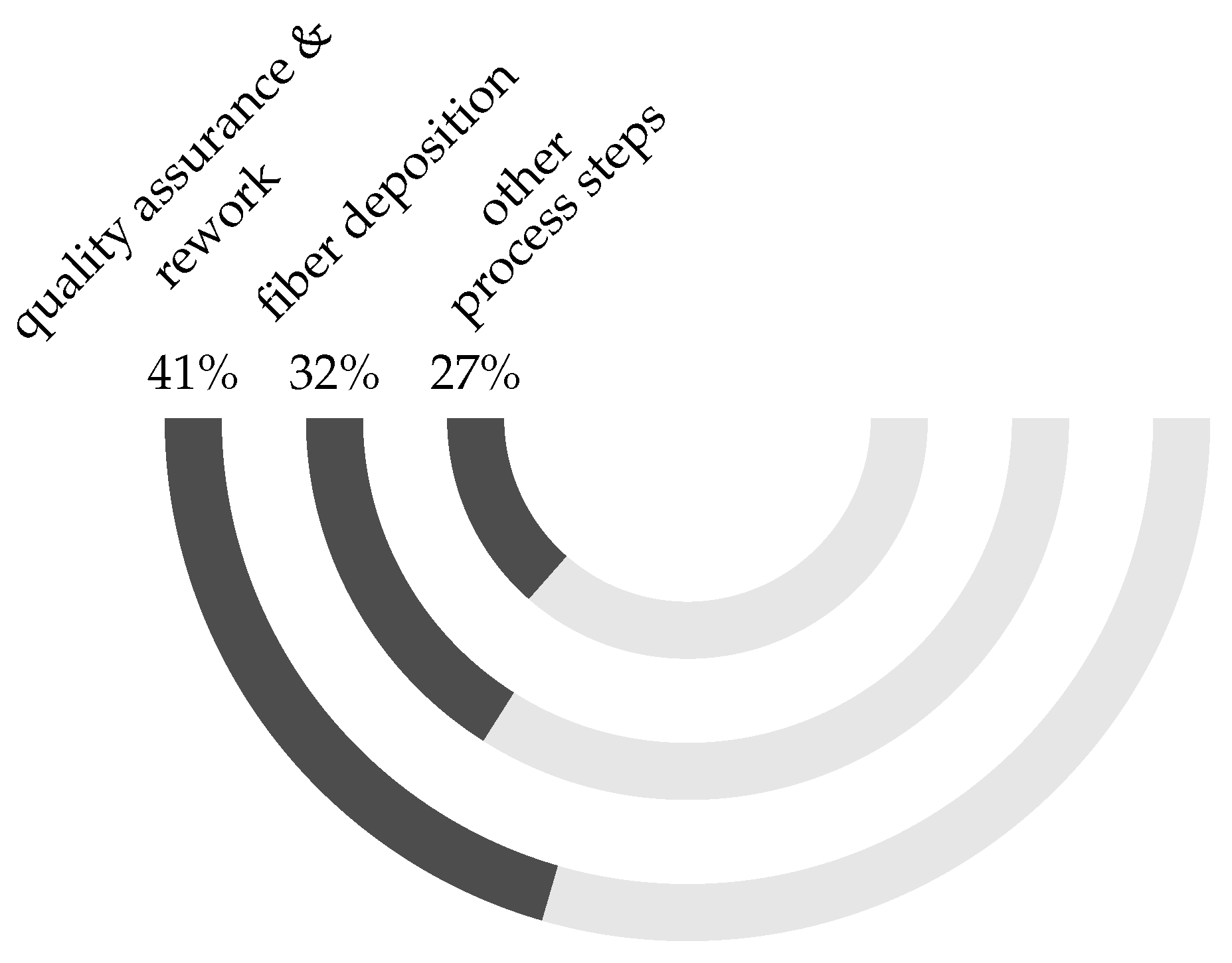
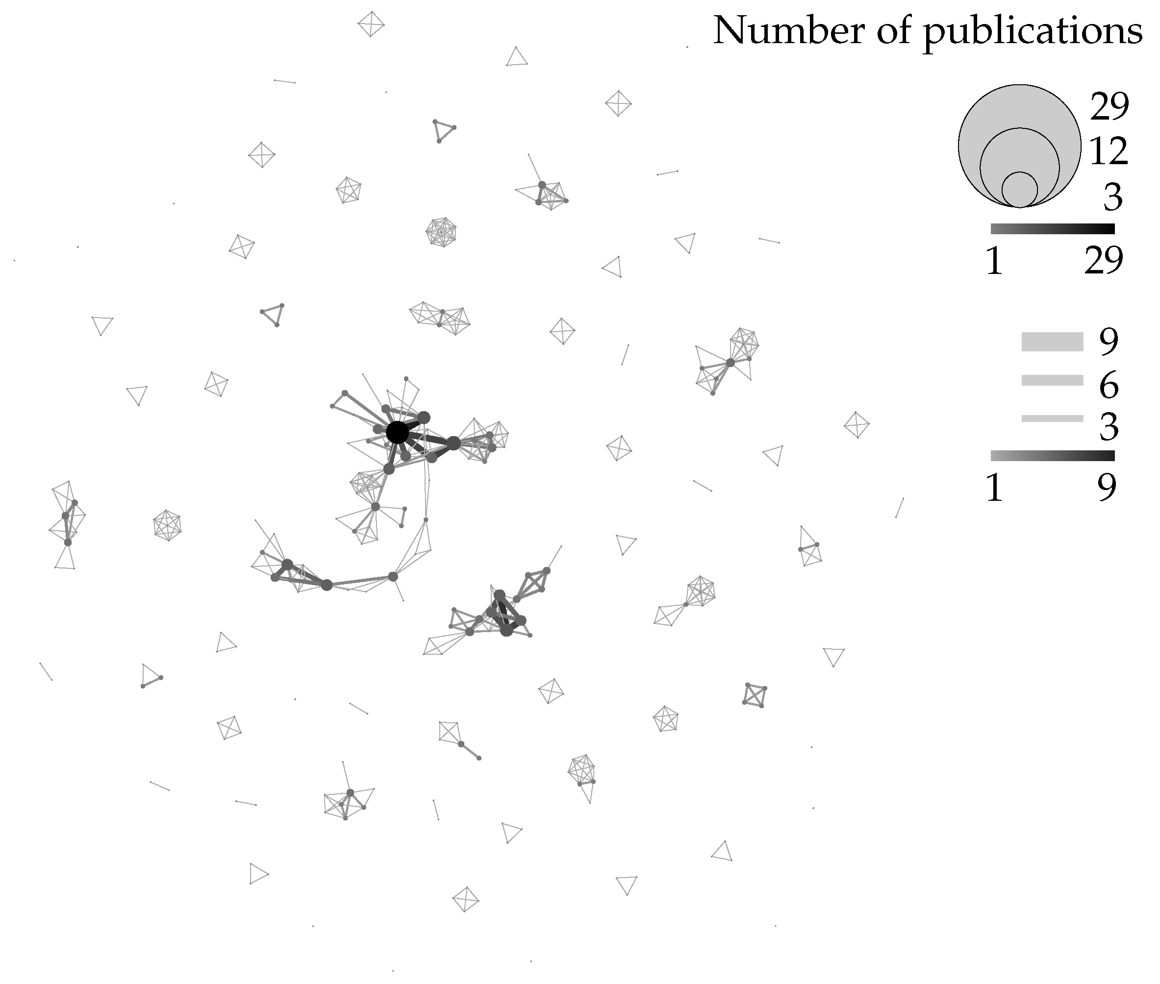
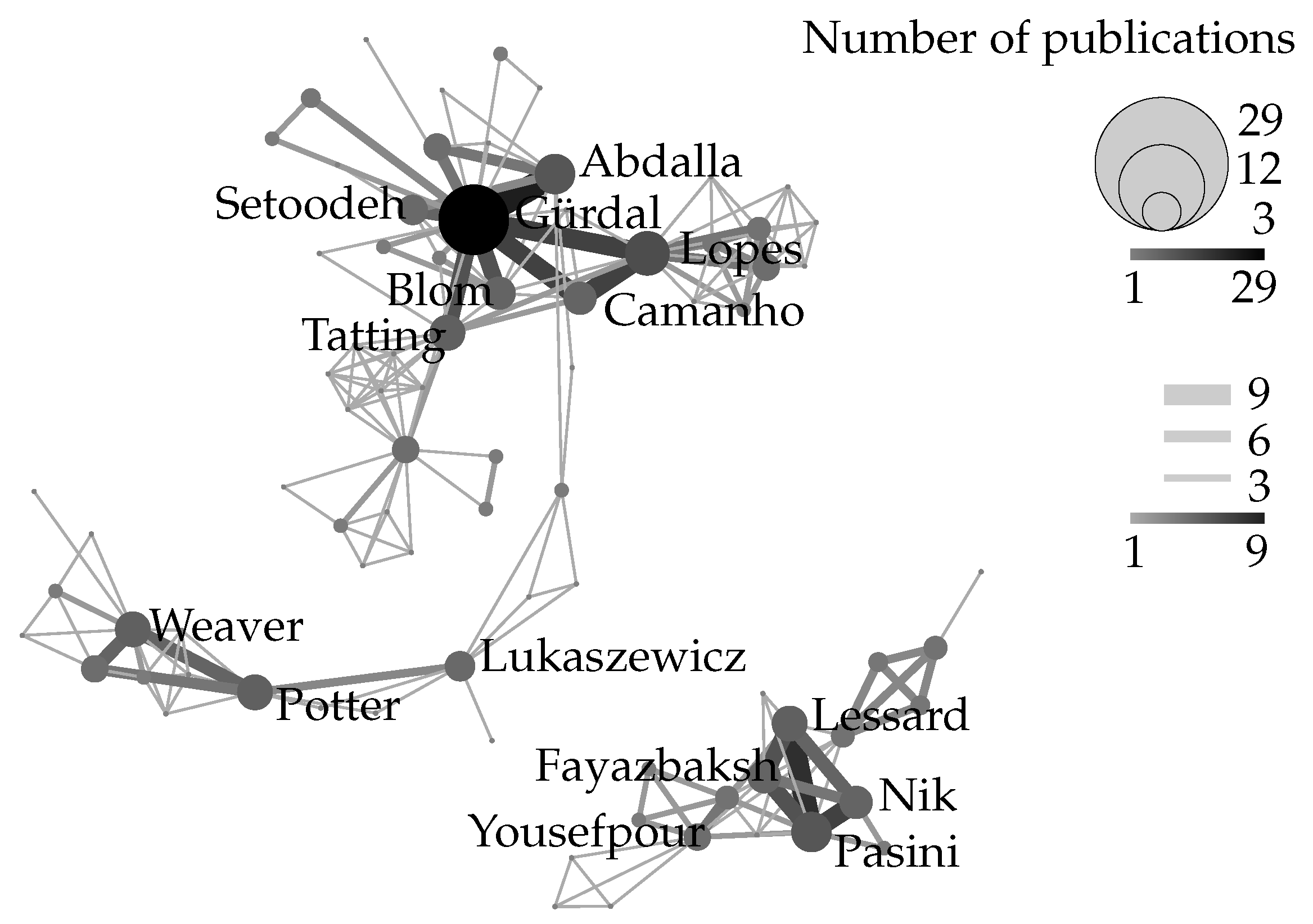
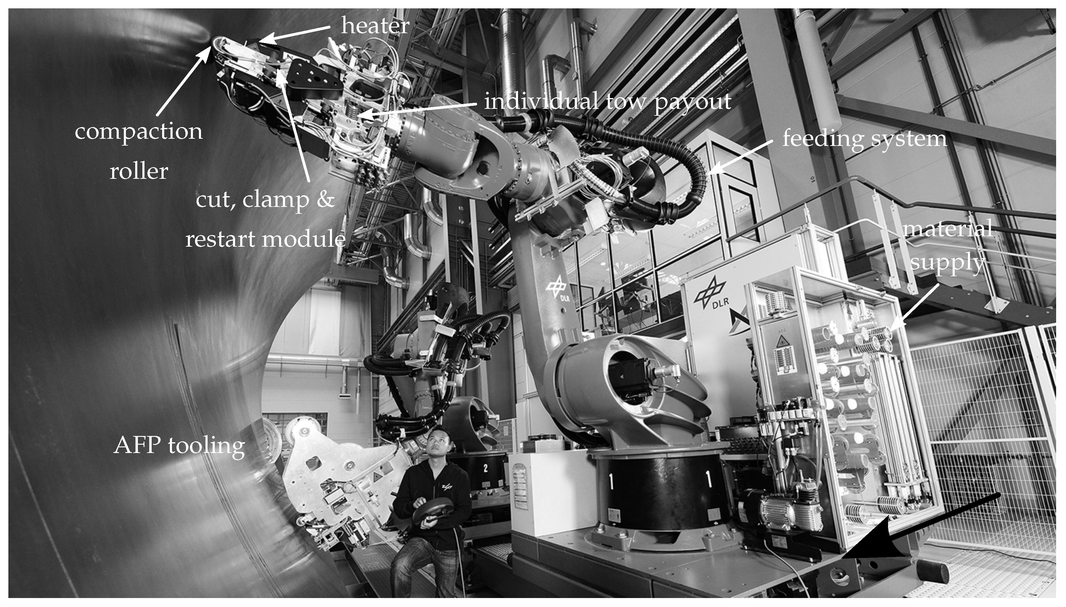
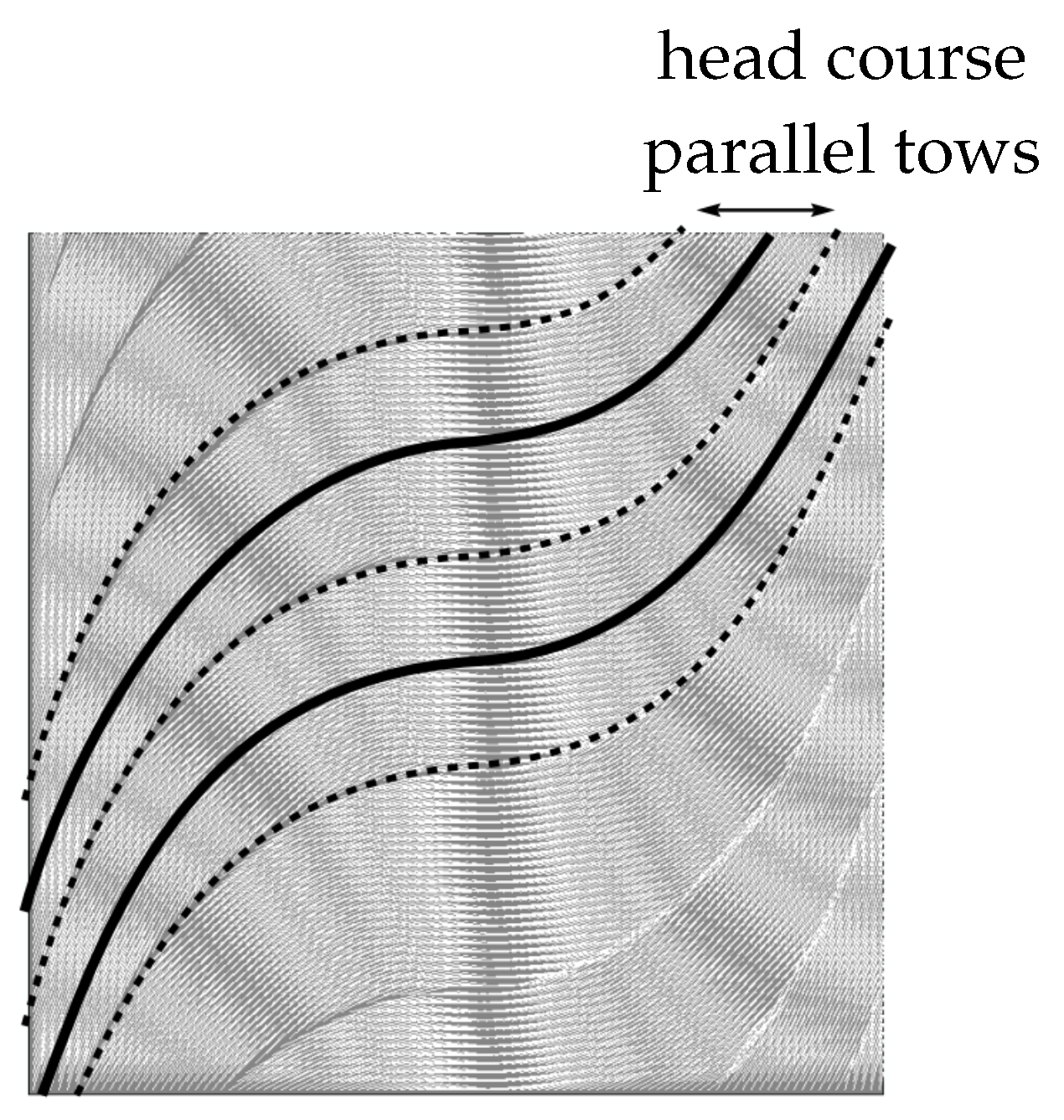
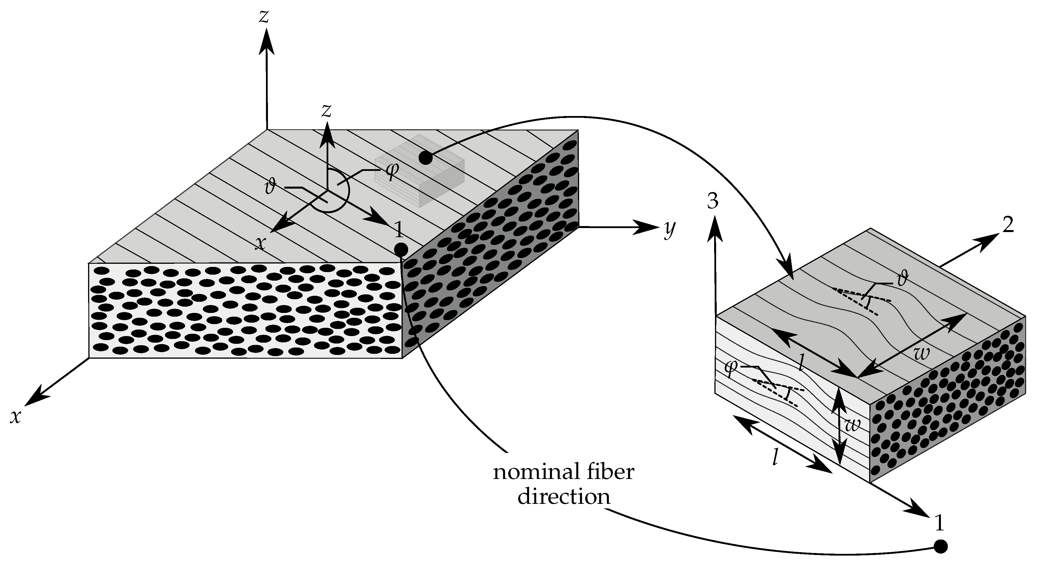
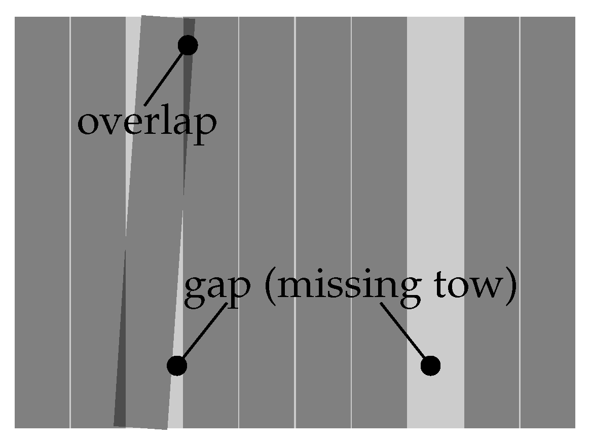
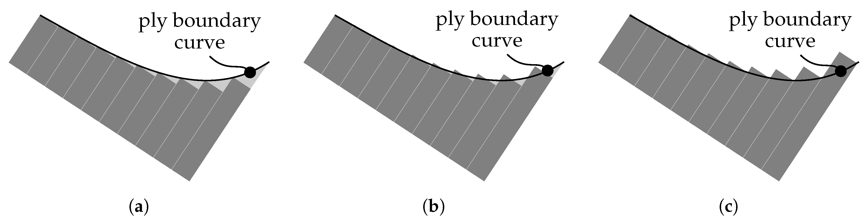
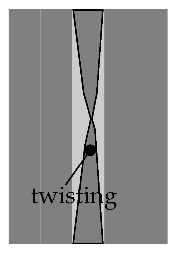
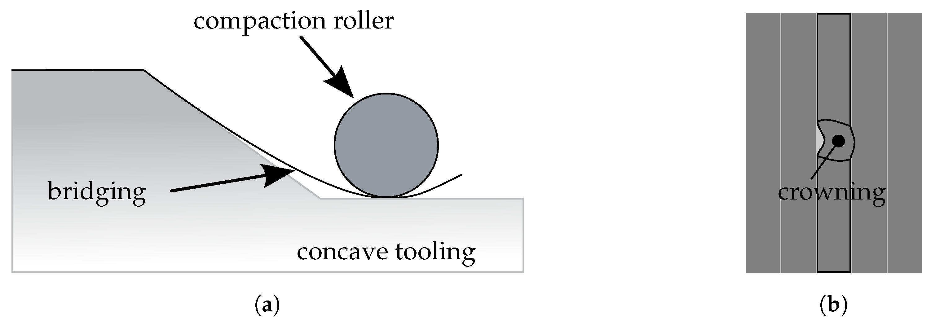
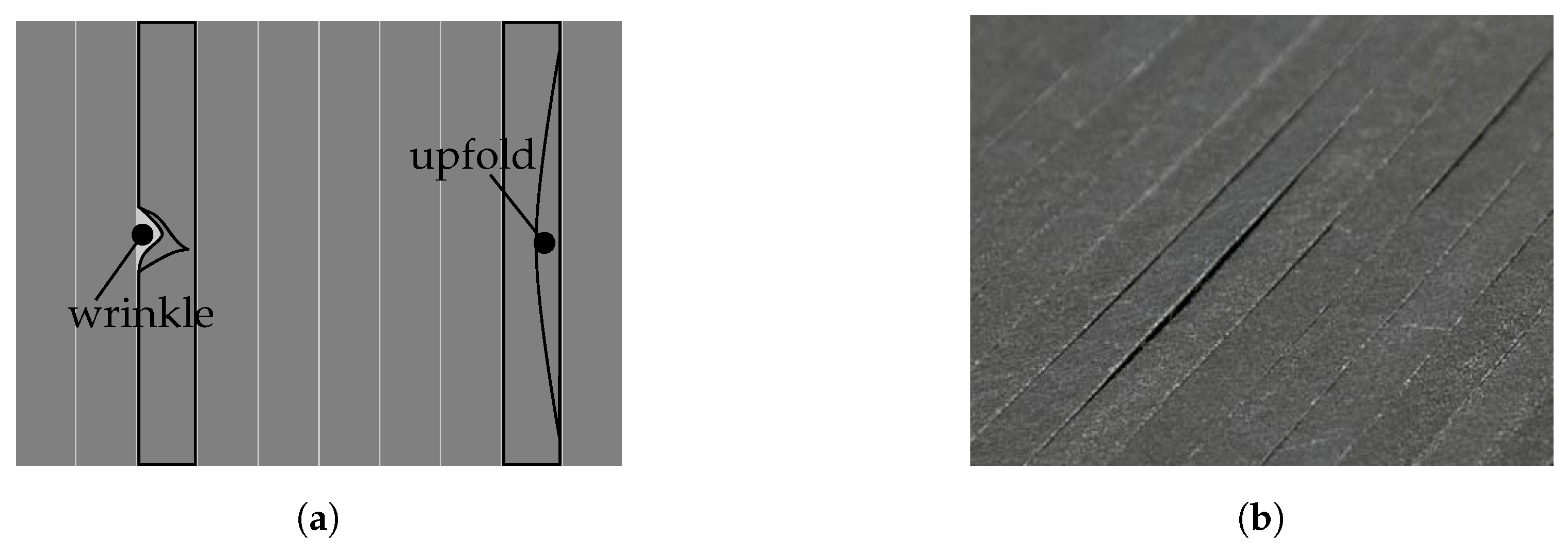
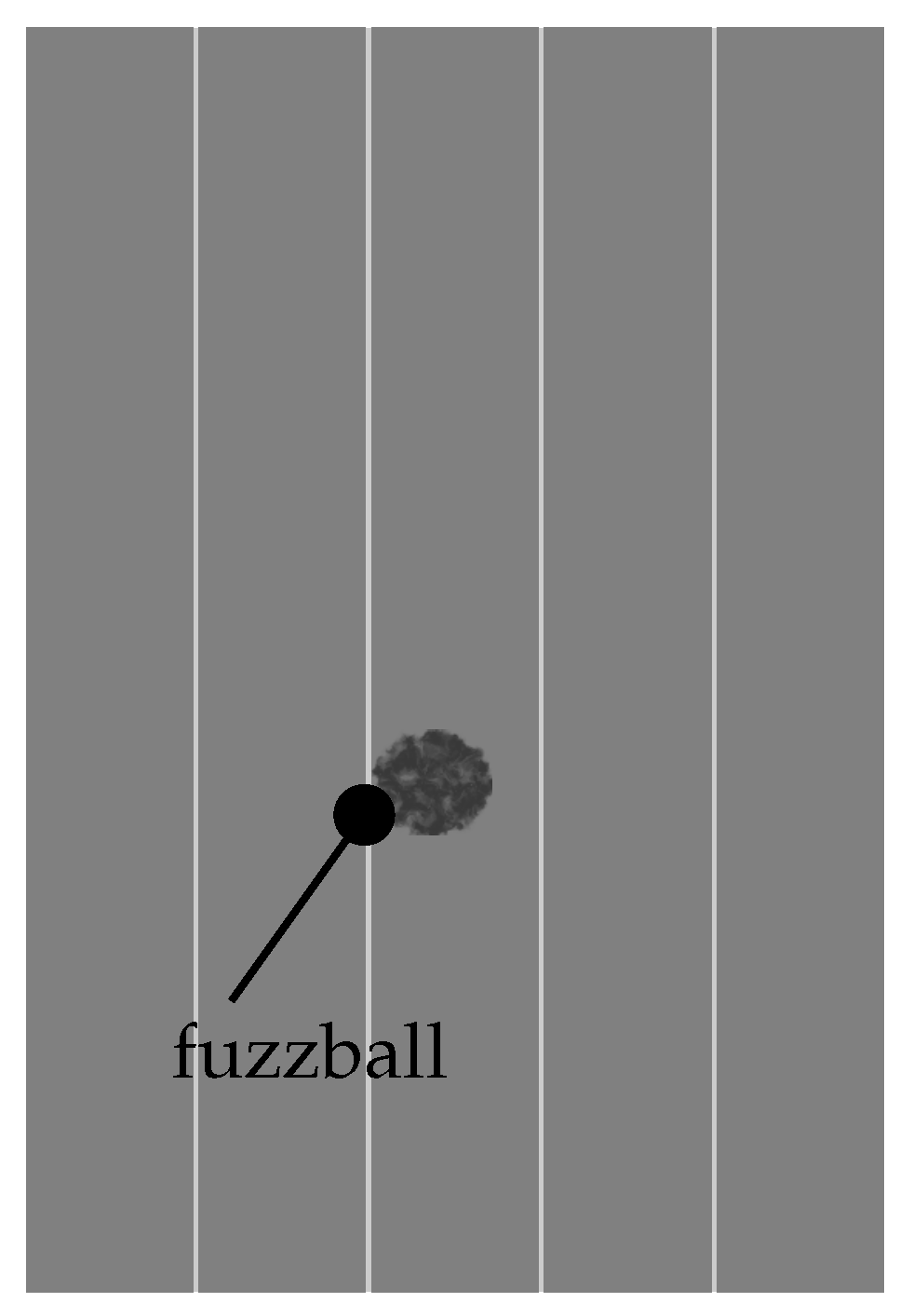
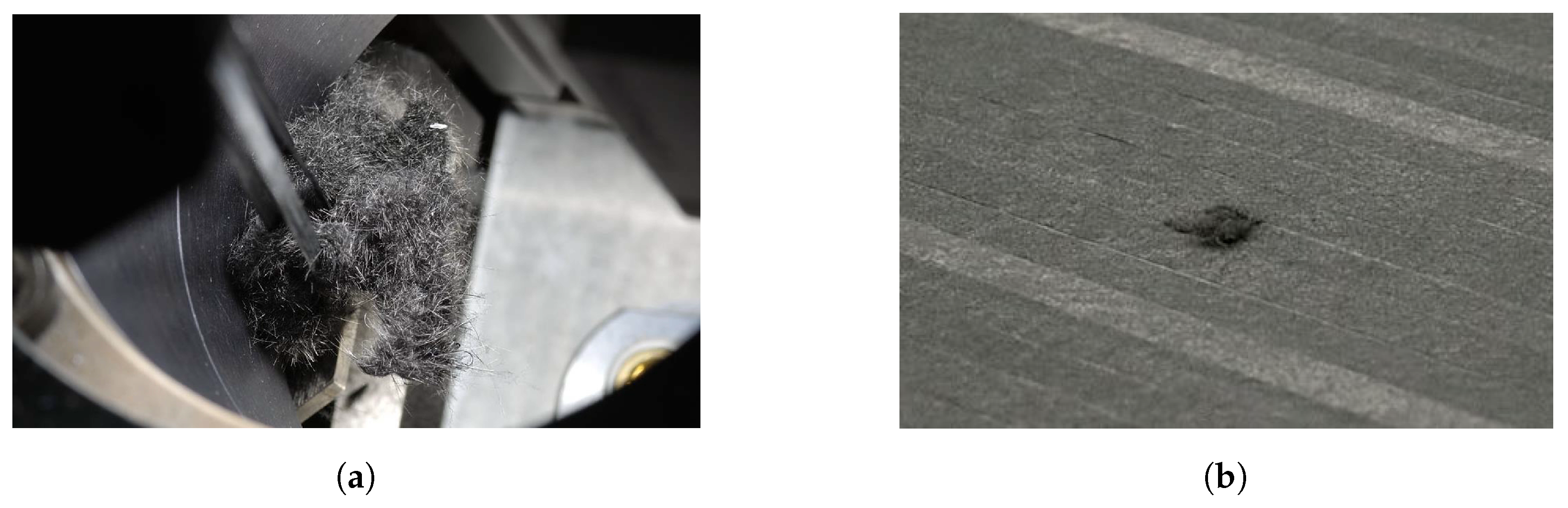
Table 1.
Overview of ATL and AFP manufactured aircraft components. The number of automated manufactured aircraft components increases, i.e., highlift devices (ailerons, flaps and spoilers), engine casing components (inlet cauling, thrust reverser and fan), wing and empennage primary structures (spar, rib, stringer, skin and trailing edge) and fuselage primary structures (skin and stringer).
| Manufacturer | Type | Components |
|---|---|---|
| Boeing [10,11,19,20,21,22] | 777, 787 V-22 Osprey | wing, empennage, fuselage |
| Airbus [9,10,20,21,22] | A319/A320/A321, A330/A340, A350, A380, A400M | empennage, wing, fuselage |
| Bombardier [20] | C-Series | fuselage |
| Fairchild Dornier [10] | Do 728 | empennage |
| Gulfstream Aerospace [10] | Gulfstream IV | wing |
| Dassault Aviation [10] | Dassault Falcon | empennage |
| Hawker Beechcraft Corporation [11,20] | Premier 1, Hawker 4000 | fuselage |
| Northrop [9,10] | B-2 | wing |
| Grumman Aerospace Corporation [10] | A-6 Intruder | wing |
| Vought Aircaft [10,11,21] | C-17 | empennage |
| Lockheed Martin [10,11,20] | F-22, F-35, C-130 | wing, empennage |
| Eurofighter [10] | Eurofighter Typhoon | wing |
Table 2.
Summary of potential secondary effects that may accompany or result from of manufacturing- induced primary imperfections. This overview bases on the performed literature review, from which the proposed classification of imperfections into the types I–X emerges.
Table 2.
Summary of potential secondary effects that may accompany or result from of manufacturing- induced primary imperfections. This overview bases on the performed literature review, from which the proposed classification of imperfections into the types I–X emerges.
| Secondary Imperfection | |||||||||||
|---|---|---|---|---|---|---|---|---|---|---|---|
| Type I | Type II | Type III | Type IV | Type V | Type VI | Type VII | Type VIII | Type IX | Type X | ||
| Primary Imperfection | Type I | • | • | • | |||||||
| Type II | • | • | • | ||||||||
| Type III | • | ||||||||||
| Type IV | • | • | • | ||||||||
| Type V | • | • | • | • | |||||||
| Type VI | • | • | |||||||||
| Type VII | • | • | • | • | |||||||
| Type VIII | • | • | • | ||||||||
| Type IX | - | - | - | - | - | - | - | - | - | ||
| Type X | • | • | • | ||||||||
© 2019 by the authors. Licensee MDPI, Basel, Switzerland. This article is an open access article distributed under the terms and conditions of the Creative Commons Attribution (CC BY) license (http://creativecommons.org/licenses/by/4.0/).
Share and Cite
MDPI and ACS Style
Heinecke, F.; Willberg, C. Manufacturing-Induced Imperfections in Composite Parts Manufactured via Automated Fiber Placement. J. Compos. Sci. 2019, 3, 56. https://doi.org/10.3390/jcs3020056
AMA Style
Heinecke F, Willberg C. Manufacturing-Induced Imperfections in Composite Parts Manufactured via Automated Fiber Placement. Journal of Composites Science. 2019; 3(2):56. https://doi.org/10.3390/jcs3020056
Chicago/Turabian StyleHeinecke, Falk, and Christian Willberg. 2019. "Manufacturing-Induced Imperfections in Composite Parts Manufactured via Automated Fiber Placement" Journal of Composites Science 3, no. 2: 56. https://doi.org/10.3390/jcs3020056