
Real-Time FPGA-Based Object Tracker with Automatic Pan-Tilt Features for Smart Video Surveillance Systems


1
CSIR—Central Electronics Engineering Research Institute (CSIR-CEERI), Pilani 333031, Rajasthan, India
2
Electronic Science Department, Kurukshetra University, Kurukshetra 136119, Haryana, India
*
Author to whom correspondence should be addressed.
J. Imaging 2017, 3(2), 18; https://doi.org/10.3390/jimaging3020018
Submission received: 14 December 2016
/
Revised: 3 May 2017
/
Accepted: 25 May 2017
/
Published: 31 May 2017
Abstract
:The design of smart video surveillance systems is an active research field among the computer vision community because of their ability to perform automatic scene analysis by selecting and tracking the objects of interest. In this paper, we present the design and implementation of an FPGA-based standalone working prototype system for real-time tracking of an object of interest in live video streams for such systems. In addition to real-time tracking of the object of interest, the implemented system is also capable of providing purposive automatic camera movement (pan-tilt) in the direction determined by movement of the tracked object. The complete system, including camera interface, DDR2 external memory interface controller, designed object tracking VLSI architecture, camera movement controller and display interface, has been implemented on the Xilinx ML510 (Virtex-5 FX130T) FPGA Board. Our proposed, designed and implemented system robustly tracks the target object present in the scene in real time for standard PAL (720 × 576) resolution color video and automatically controls camera movement in the direction determined by the movement of the tracked object.
1. Introduction
Visual object tracking, one of the most significant tasks of smart video surveillance system, is usually performed in the context of higher-level visual surveillance applications that require the location of the object in every frame [1]. The importance of visual object tracking comes from the fact that it has a wide range of real-world applications, including surveillance and monitoring of human activities in residential areas (parking lots and banks) [2,3], smart rooms [4,5], traffic flow monitoring [6], traffic accident detection [7], hand gesture recognition [8], mobile video conferencing [9], video compression [10,11] and enabling an unmanned ground vehicle to handle a road intersection [12].
Development of a real-time object tracking system is a very challenging task due to issues arising from the motion of the camera, complex object motion, the complex background of the scene (the presence of other moving objects) and real-time processing requirements. These challenges may cause tracking degradation and even failures. In order to deal with these different challenges, researchers have used numerous approaches for object tracking. These algorithms usually focus on different problems in visual object tracking and, thus, have different properties and characteristics, resulting in different responses and performances for the same input video sequences. They primarily differ from each other based on the choice/selection of the object representation scheme, image features space and the camera/object motion modeling scheme. The choice/selection relies heavily on the specific context/environment of the tracking task and the end use for which tracking information is being sought. In the literature, a large number of tracking methods has been proposed, which provide the appropriate selection of the above parameters for a variety of scenarios. Detailed surveys of these algorithms were presented by Yilmaz et al. [1], Li et al. [13] and Porikli [14]. Most of these algorithms either simplified their domains by imposing constraints on the class of objects they can track [15,16,17] or assumed that the camera is stationary and exploited background subtraction/segmentation [18,19,20,21,22]. Peddigari and Kehtarnavaz [23] have reported a real-time predictive zoom tracker, but it works only for digital static cameras. In all of these approaches, if the background changes due to camera movement, the whole system must be initialized again for capturing background information. Therefore, these approaches work only for fixed backgrounds; thus limiting their applications for stationary camera systems.
Several researchers have proposed and published algorithms for object tracking that did not assume constant background. The object trackers based on condensation [24], covariance matrix matching [25], normalized correlation [26], active contours [27,28], appearance modeling [29], incremental principal component analysis [30], the kernel scheme [31,32,33,34] and the particle filter [35,36,37] can track the object of interest even in the presence of camera motion. Gupta et al. [38] have combined the Eigen tracker and particle filter to design a predictive appearance-based tracker, but it has the overheads of non-linear optimizations. Ho et al. [39] have proposed a fast appearance tracker that eliminates non-linear optimizations completely, but it lacks the benefits of the predictive framework. Tripathi et al. [40] have enhanced the capabilities of the Eigen tracker by augmenting it with a condensation-based predictive framework to increase its efficiency and also made it fast by avoiding non-linear optimizations. They have reported that their tracker tracks robustly for real-world scenarios, with changing appearance, lighting variations and shadowing, as well as pose variations. However, the claimed frame rate for 320 × 240 resolution videos on an Intel Centrino P4 1.8-GHz machine was 0.25 frames per second, which is 100-times slower than the real-time requirement of 25 frames per second. Most of the algorithms proposed in the literature and discussed above for object tracking in dynamic backgrounds are computationally too expensive to be deployed on a moderate computing machine for a practical real-time tracking surveillance application. Color histogram-based object trackers were proposed by Adam et al. [41] and Porikli et al. [42] that are fast and computationally simple. These match the color histogram of the target object with every possible region in the whole frame. Since the histogram does not contain the spatial information and there is a risk of picking up the wrong target having similar histograms [43], therefore these trackers are not adequately robust.
The recent trend in object tracking algorithm/system development is to exploit the machine learning/pattern recognition techniques for designing object tracking systems with Tracking, Learning, and Detection (TLD) capabilities [44]. Such object trackers not only track the objects in a video stream, but also learn with time about the changing characteristics or appearance of the tracked object. This feature makes them robust as compared to other tracking techniques. The TLD type of trackers can also detect the tracked object if it goes out and appears in the scene after some time. The computational complexity of these trackers is high due to the use of sophisticated machine learning/pattern recognition techniques. A recent experimental survey of different object trackers is available in [45]. In this survey, the authors have considered in total nineteen trackers, which are grouped into five different categories, namely tracking using matching, tracking using matching with the extended appearance model, tracking using matching with constraints, tracking using discriminative classification and tracking using discriminative classification with constraints.
In parallel with robust and efficient algorithm developments, many researchers have proposed hardware architectures for object tracking algorithms, to achieve real-time performance for use in real-world surveillance applications. In 2005, Johnston et al. [46] made an initial attempt to design an FPGA-based remote object tracking system for real-time control on the Xilinx Spartan-II XC2S200 FPGA using simple morphological filtering and the bounding box-based approach. Instead of 24-bit RGB pixel data, they have used 16-bit (5:6:5) RGB pixel data. There is no detailed discussion about the object tracking results in their published article.
An FPGA-based object tracking system, using the image segmentation-based approach for a static background, was proposed by Yamaoka et al. [47]. It was designed and tested for the video resolution of 80 × 60 pixels. There are no discussions in the paper on the input/output video interfaces. Liu et al. [48] have also implemented object tracking on FPGA for 80 × 60 pixel size downscaled images using background subtraction. Kristensen et al. [49] have designed and presented a complete video surveillance system with input/output video interfaces for real-time object tracking using the background segmentation approach. Their implementation can track objects at a frame rate of 30 frames per second. The system was designed for a video resolution of 320 × 240 pixels, which is rather low as compared to the resolutions used by modern digital video surveillance systems. More recently, Chan et al. [50] have developed an IP camera-based surveillance system using both the FPGA and the general purpose processor-based server. Their implementation is capable of processing 60 frames per second for PAL (720 × 576) size video resolution. As all four implementations [47,48,49,50] have used background segmentation-based approaches, they can do object tracking only in static background scenarios.
Xu et al. [51] have proposed a VLSI architecture for active shape module for application in people tracking, and Shahzada et al. [52] have designed an image coprocessor for an object tracking system. The authors of both of these implementations have compared their performance results with standard software implementations without any discussions on their use or extensions for real-time object tracking application. Some embedded implementations of object trackers using EDK (Embedded Development Kit)-based tools were also presented by Raju et al. [53,54]. In these implementations, only the issues were discussed, and a few IPs were designed. They fell short of a complete system design and associated real-time performance results.
Several researchers [55,56,57,58] have tried to address the real-time aspects of dynamic background object trackers using hardware/FPGA-based implementations, but none of them have discussed or reported the details of input/output video interface design, real-time results, frame resolutions and frame rates. Hardware architectures have also been proposed for the color segmentation-based object tracking algorithm [59] and mean-shift object tracking algorithm [60]. Recently, many researchers have used color histogram and/or particle filter-based object tracking schemes and designed their hardware architectures [61,62,63,64]. In their implementations, the maximum size considered for the object of interest was 32 × 32 pixels [61], and the maximum number of particles considered was 31 [62]. As the number of particles considered directly effects the robustness of the tracker, their robustness is relatively low. A comparison of these hardware implementations with our research results will be presented in the section on the synthesis results.
Based on the available literature, it is observed that there are the following main issues that need to be addressed for the design of a complete object tracking system for its use in real-time surveillance applications:
- ▪
- Real-time data capturing from the camera and on-the-fly processing and display need to be implemented.
- ▪
- The frame size should be of PAL (720 × 576) resolution, which is projected to be the most commonly-used video resolution for current generation video surveillance cameras.
- ▪
- The design of the external memory interface for storing the required number of intermediate frames necessary for robust object tracking (requirement depends on algorithm) needs to be addressed as on-chip FPGA memory (Block RAMs) is not enough for storing standard PAL (720 × 576) size multiple video frames.
- ▪
- The current generation of automated video surveillance systems requires a camera with Pan, Tilt and Zooming (PTZ) capabilities to cover a wide field of view; and these must be controlled automatically by system intelligence rather than manual interventions. Therefore, the design and implementation of a real-time automatic purposive camera movement controller is another important issue that needs to be addressed. The camera should move automatically to follow the tracked object over a larger area by keeping the tracked object in the field of view of the camera.
Keeping in view all of the above issues that are important for an object tracking system, in this paper, we purpose and develop a real-time object tracking system with automatic purposive camera movement capabilities. An object tracking scheme based on particle filtering, color histogram and the sum of absolute differences that can handle camera movement and background change issues has been implemented. To increase the robustness of the system, we have considered 121 particles as compared to 31 particles by [62] and the maximum tracked object size of 100 × 100 pixels as compared to 32 × 32 pixels by [61]. To achieve real-time performance for PAL (720 × 576) resolution videos, for the implemented object tracking scheme, a dedicated VLSI architecture has been designed and developed. To store the large amount of video data, as needed during object tracking, the DDR2 external memory interface has been designed and integrated. To provide real-time purposive camera movement, the camera movement controller is designed. Based on the inputs from the object tracking architecture, the camera movement controller moves the camera automatically in the XY-plane to follow the tracked object and keep it in the field of view of the camera as long as possible. By integrating the designed dedicated object tracking VLSI architecture with the camera interface controller, the DDR2 external memory interface controller, the camera movement controller and the DVI display controller, a complete robust working prototype of an FPGA-based real-time object tracking system with automatic purposive camera movement capabilities has been developed.
2. Object Tracking Algorithm
In this section, we describe our implemented object tracking method. For the detailed description of the original color-based particle filtering approach, refer to [37,65]. In our implementation, the Sum of Absolute Difference (SAD) information for similarity computation between the target object image and computed particle images is used to enhance the accuracy of the tracker. Our implemented tracking scheme is computationally simple and, therefore, hardware implementation friendly. Furthermore, this tracking scheme does not assume a static background and, therefore, is suitable for tracking objects using an active PTZ camera to follow the tracked object in larger fields of view. We have considered 121 particles and the maximum tracked object size of 100 × 100 pixels. The implemented algorithm is described below.
Initially, a box of a 100 × 100 pixel size appears in the middle of the frame. The object to be tracked must be within this box. If it is not, it is brought into this box by moving the camera towards the object to be tracked (the camera used is a pan-tilt-zoom camera; therefore, it can easily be moved in any direction). Once the object becomes static in the box, the 100 × 100 size color image of the object to be tracked is stored in the memory as the reference image of the object of interest. This reference image is used during the tracking procedure in subsequent frames of the video.
The reference color histogram of the object of interest is computed by using the stored 100 × 100 pixel size reference color image. The histogram is computed for each R, G and B color channel separately. We have considered 26 bins (0–9, 10–19, 20–29,…, 240–249, 250–255) for each color channel’s histogram for enhancing the accuracy. Maximum tracked object movement in any direction from one frame to the next frame is 20 pixels. Maximum 20 pixel movement in two consecutive frames allows tracking the object even if it enters and moves out of a scene in a one-second duration for PAL size color videos. In order to cover the complete region of 20 pixels’ movement in any direction, we have considered 121 particles around the location of the tracked object in the previous frame. This increases the accuracy of the tracking process. After this initialization, the following steps are performed for each frame:
- (1)
- As we have considered a maximum of 20 pixels’ movement of the tracked object in any direction from one frame to the next frame, therefore, 121 particles (each of size 100 × 100 pixels) around the location (X, Y) of the tracked object in last frame are considered to cover the complete region of 20 pixels’ movement in any direction. The location of each particle with respect to location (X, Y) of the tracked object in the previous frame is shown in Figure 1. For each particle, a 100 × 100 pixel image is extracted from the stored current frame based on the coordinate values shown in Figure 1.
- (2)
- The color histogram (for each R, G and B color channel) for each particle is computed by using the 100 × 100 pixel image of each particle. The absolute difference of each bin (a total of 26 bins for each color channel is considered as mentioned above) of each R, G and B color channel for each particle is computed with respect to their corresponding bins in the reference histogram of the tracked object (the reference image histogram is computed during the initialization phase as mentioned earlier in this section).
- (3)
- Next, the absolute difference values for each bin are added for each color channel separately, and finally, the three color channels’ values are added up. This results in the histogram difference value (denoted as Histogram_Difference). This histogram difference is computed for each particle.
- (4)
- In addition to the above, the Sum of Absolute Differences (SAD) is also computed for each particle with respect to the reference image of the tracked object.
- (5)
- The above process results in a total of 121 Histogram_Difference values and 121 SAD values. Now, the respective SAD value and the Histogram_Difference value are added up for each particle. This value is connoted as Histogram_Difference_Plus_SAD. Thus, in all, there are 121 values of Histogram_Difference_Plus_SAD.
- (6)
- The particle with minimum Histogram_Difference_Plus_SAD value among the 121 Histogram_Difference_Plus_SAD values is the best matched particle, and the location of this particle is the location of the rectangle for the tracked object in this current frame. The coordinates of this particle are computed, and a rectangle of a 100 × 100 pixel size is drawn using these coordinates.
- (7)
- The location of this particle will become the reference location for the next frame. In the next frame, 121 particles will be considered around this location. For every new frame, Steps 1–7 will be repeated.
We have implemented the above-mentioned object tracking scheme in the C/C++ programming language. For running the code, a Dell Precision T3400 workstation (with Windows XP operating system, quad-core Intel® Core™ 2 Duo Processor with 2.93-GHz operating frequency and 4 GB RAM) was used. The Open Computer Vision (OpenCV) libraries have been used in the code for reading video streams (either stored or coming from camera) and displaying object tracking results. The achieved frame rate for software implementation is much lower than that required for real-time performance. To achieve real-time performance, we have designed a dedicated hardware architecture for the above-mentioned scheme and implemented it on the FPGA development platform. The details for the same are discussed in the remaining sections of this paper.
3. Implemented Object Tracking System
A simplified conceptual block diagram of the proposed and implemented FPGA-based real-time object tracking system using the Xilinx ML510 (Virtex-5 FX130T) FPGA platform (Xilinx, Inc., San Jose, CA, USA) is shown in Figure 2 to illustrate the data flow within the system. The main components of the complete FPGA-based standalone object tracking system are: analog camera, VDEC1 Video Decoder Board for analog to digital video conversion, custom-designed interface PCB, Xilinx ML510 (Virtex-5 FX130T) FPGA platform for performing real-time object tracking with automatic camera movement and a display device (display monitor).
Input video, captured by a Sony Analog Camera (EVI-D70P, Sony, Tokyo, Japan), is digitized by the Digilent VDEC1 Video Decoder Board. The digital output signals from the video decoder board are transferred to the FPGA platform using high speed I/O ports (HSIO PINS) available on the Xilinx ML510 (Virtex-5 FX130T) FPGA Board using the custom-designed interface PCB. The components inside dashed blue line are available on the Xilinx ML510 (Virtex-5 FX130T) FPGA Board. These include the FPGA device (shown by the dashed red line), external DDR2 memory, High Speed Input Output Interface (HSIO PINS), the UART port and the DVI interface port. The camera interface module uses the digital video signals available at the FPGA interface to extract RGB data and generate video timing signals. The DVI display controller is used to display the processed data on the display monitor.
The object tracking algorithm requires storage of complete incoming and processed video frames. As the on-chip memory (block RAMs) on the Xilinx ML510 (Virtex-5 FX130T) FPGA Board is not sufficient to buffer this large amount of video data, therefore external DDR2 memory available on the Xilinx ML510 (Virtex-5 FX130T) FPGA Board is used to store the video frames (incoming and processed). For this purpose, the DDR2 external memory interface is designed and integrated. This interface writes the incoming pixel data into the external DDR2 memory and sends the processed output data to DVI display controller for display on the monitor, connected through the DVI interface port. The object tracking module receives the image pixel data from the external DDR2 memory and writes back the processed data to the external DDR2 memory through the DDR2 external memory interface. Camera movement controller is designed to generate the commands for purposive movement of the camera in horizontal/vertical/diagonal directions to follow the tracked object. The commands are generated based on the inputs (coordinates of new location of tracked object) from the object tracking module and are transferred to the PTZ camera through the UART port available on the FPGA development platform.
We have used the Sony EVI-D70P camera (Sony, Tokyo, Japan). This camera has pan, tilt and zoom features, and these must be controlled automatically based on the outputs from the object tracking module running on the FPGA. For this purpose, a dedicated camera movement controller has been designed. It takes inputs from the object tracking module running on FPGA and timing signals from the video timing generation block, generates the necessary commands for purposive movement of the camera based on the inputs received and sends these commands to the camera through the UART port available on the Xilinx ML510 (Virtex-5 FX130T) FPGA development board. It has four main modules as shown in Figure 3.
The first two modules, working in parallel, are the camera movement direction computation block and the camera movement speed computation block. These two blocks respectively compute the camera movement direction and camera movement speed based on the new location parameters and the last stored location parameters of the object of interest (target object), as well as storing these new parameter values for future reference. The camera command generation module generates necessary commands for controlling the desired camera movement. In order to stop the camera, each camera movement command must be followed by a camera stop command. The generated commands are sent to the RS232 controller, which sends these commands to the camera. The camera receives the movement control commands through a cable which connects the VISCA RS232 IN port of the camera to the UART port of the Xilinx ML510 (Virtex-5 FX130T) FPGA board.
3.1. Proposed and Implemented Object Tracking Architecture
The VLSI architecture designed and implemented by us for the proposed particle filtering, color histogram and SAD-based object tracking scheme is shown in Figure 4. The input data to the object tracking architecture are coming from the DDR2 external memory interface. It is 48-bit data. As the DDR2 external memory interface performs two write/read operations in one clock cycle (one at the rising edge and the other at the falling edge), two pixel data become available in each clock cycle. One of the pixel data is 24 bits wide (eight bits each for the R, G and B color channels). The controller receives the control signals (video timing) from the camera interface module and generates the control signals for all the internal blocks of the object tracking architecture. These control signals ensure proper functioning and synchronization of all of the internal modules of the architecture.
The 48-bit pixel data coming from the external DDR2 memory via the DDR2 external memory interface is routed to the WData inputs of the REF-MEM, the PE1-MEM, the PE2-MEM and the PE3-MEM memories. During the initialization process (performed during the initial few frames), the reference image of the object to be tracked is stored in the REF-MEM and then used during the tracking procedure. For this purpose, the switch available at the input of memories is connected to the WData input of the REF-MEM for the initial few frames. Once the reference image of the object to be tracked is stored in the REF-MEM, the tracking process begins. For all subsequent frames, the switch available at the input of memories will remain connected to the WData inputs of PE1-MEM, PE2-MEM and PE3-MEM memories. The size of the object to be tracked is considered as 100 × 100 pixels. Therefore, REF-MEM is of a size of 100 × 50 × 48 bits: 100 being the number of rows, 50 being the number of columns and 48 bits being the bit-size of each location (as two pixels’ data = 48 bits is read/written during each clock cycle). The REF-MEM address unit generates the Address for Reading (RADD), the Address for Writing (WADD) and the Write Enable (WEN) signal. Two clocks signals, clk1 and clk2, provide timing to the REF-MEM and the REF-MEM address units: data are written at clk1 clock frequency and are read at clk2 clock frequency. This is because data from the external DDR2 memory arrives at a different clock frequency (200 MHz) than the clock frequency (125.8 MHz) used by the processing unit.
After the initial reference image of the object to be tracked is written in REF-MEM, the color histogram of the 100 × 100 pixel reference image is computed by the REF HIST module. This module takes 48-bit data (two pixel RGB data in one cycle) as input. Color histograms are computed separately for each of the R, G and B color channels. For each color channel histogram, 26 bins are used for getting enhanced accuracy. These bins are for eight-bit data values from 0–9, 10–19, 20–29, 30–39, 40–49,…, 240–249 and 250–255. The outputs of the REF HIST block are Histogram Bins for the R, G and B color channels (i.e., HBR, HBG and HBB). Each of these outputs contains the 26 bin values separately.
Now, for all of the subsequent frames, the objective is to track the object of interest. This is done by computing the histograms and SAD values for the 121 particles in the current frame. Computation of histograms and SAD values for the 121 particles requires the reading of 121 images of a 100 × 100 pixel size in each frame. In addition to this, one PAL (720 × 576) size input color image is written to the external DDR2 memory, and one PAL (720 × 576) size processed output color image is read from the external DDR2 memory for sending to the display device. All of these operations put a lot of demand on the external memory bandwidth. To address this issue, we have developed a novel architecture in which all 121 particles of 100 × 100 pixel size images are read in one go. The details are explained below.
The size of the tracked object is 100 × 100 pixels, and the maximum movement of the tracked object from one frame to the next frame is 20 pixels in any direction. For this reason, 121 particles (each of size 100 × 100 pixels) around the location (X, Y) of the tracked object in the last frame are considered to cover the complete region of 20 pixel movement in any direction (shown in Figure 1 in the algorithm section). Therefore, in the current frame, an image of a 140 × 140 pixel size contains all of the images of the 100 × 100 pixel size for the 121 particles. The location of the 140 × 140 pixel size image in the current frame with reference to the 100 × 100 pixel size tracked object in the last frame is shown by the red dotted bounding line in Figure 5. As per the architecture designed and developed by us, this 140 × 140 pixel size image is read just once from the external memory and stored in the on-chip (block RAMs) memory. All of the images of the 100 × 100 pixel size for the 121 particles are then read, whenever needed, from the 140 × 140 pixel size image stored in the block RAMs. This significantly reduces the external memory bandwidth requirement, but uses some extra on-chip memory.
We have used three Processing Elements (PEs) in parallel to speed up the computation process and to achieve real-time performance. Each processing element computes histogram, histogram difference, SAD and the sum of histogram difference and SAD for each particle. There are three memories associated with the three processing elements. These memories contain the images of particles. The size of each of these three processing element associated memories is 140 × 70 × 48 bits. The number of rows is 140; the number of columns is 70; and as two pixel data are read/written in each clock cycle, the bit-width of each location is 48 bits. Thus, each processing element associated memory contains the image pixel data covering the range of all ±20 pixel movements in all of the directions around the tracked object location in the last frame.
After initialization, the switch available at the input is connected to WData inputs of PE1-MEM, PE2-MEM and PE3-MEM memories in order to store the 140 × 140 pixel size image read from the external memory once only in each incoming frame. Like the REF-MEM address unit, the PE1-MEM address, PE2-MEM address and PE3-MEM address units generate the RADD and WADD along with the WEN signals for their corresponding memories (i.e., PE1-MEM, PE2-MEM and PE3-MEM, respectively). Two clocks, clk1 and clk2, are used by PEI-MEM and PEI-MEM address units (I from 1–3) because data are written to memories at clk1 clock frequency and read from memories at clk2 clock frequency. This is so because data to be written to these memories arrive from external DDR2 memory at a clock frequency of 200 MHz, while data are to be supplied by these memories to the associated processing elements at the clock frequency of 125.8 MHz. For every new frame, after reading the 140 × 140 pixel size image data from external DDR2 memory and writing it to PEI-MEM (I from 1–3), the next step is to perform the required processing on the data written to PEI-MEM (I from 1–3). The clock cycle counter (COUNT_clk2CYCLE) starts counting as the processing begins.
The processing starts by computing the histograms and SAD values for all of the 121 particles (each having the image size of 100 × 100 pixels) having starting X, Y coordinates as shown in Figure 1. Since each of these 100 × 100 × 24-bit images are stored as 100 × 50 × 48-bit images (where the number of rows is 100 and the number of columns is 50), therefore it takes 5000 clock cycles for reading each 100 × 50 × 48-bit image from PEI-MEM (I from 1–3).
In the first 5000 clock cycles, the read address for PE1-MEM memory is generated in such a way so as to read the first 100 × 100 pixel image from (X − 20, Y − 20) to (X − 20 + 100, Y − 20 + 100) locations; the read address for PE2-MEM memory is generated in such a way so as to read the second 100 × 100 pixel image from (X − 16, Y − 20) to (X − 16 + 100, Y − 20 + 100) locations; and the read address for PE3-MEM memory is generated in such a way so as to read the third 100 × 100 pixel image from (X − 12, Y − 20) to (X − 12 + 100, Y − 20 + 100) locations. These three images are for the first three particles of the first row in Figure 1. The output data (RDATA) of each PEI-MEM (I from 1–3) is taken as input by the corresponding histogram generation unit (PE-HIST) and SAD computation unit (PE-SAD).
Each PEI-HIST (I from 1–3) module takes the 48-bit data (RGB data of two pixels supplied in one cycle) as input. The color histogram is computed for each R, G and B color channel separately. For each color channel histogram, 26 bins are used for achieving enhanced accuracy. These bins are for eight-bit data values from 0–9, 10–19, 20–29, 30–39, 40–49, …, 240–249 and 250–255. The outputs of the PEI-HIST (I from 1–3) module are histogram bins for R, G and B color channels (i.e., HBR, HBG and HBB). Each of these outputs contains 26 bin values separately. These outputs, along with the outputs of the REF-HIST block, are used by the respective PE-HIST-DIFF modules for computing the histogram difference values. For this purpose, first, the absolute difference of each bin of each R, G and B color channel for each PEI-HIST (I from 1–3) is computed with respective bins of the REF-HIST module. Following this, the absolute difference values of each bin are added separately for each color channel. Finally, the three color channel values are added for computing the final sum of Histogram Difference Values (HDS).
PEI-SAD (I from 1–3) module takes 48-bit data (two pixel RGB data in one clock cycle) from PEI-MEM (I from 1–3) and the corresponding 48-bit data from REF-MEM as two inputs in each clock cycle. It computes the SAD values for each color channel separately and finally adds them together to compute the sum of SAD values (SADS).
The Sum of SAD values (SADS) and the sum of Histogram Difference Values (HDS) are added for each of the three particles, resulting in the three Sum of Processing Element (SPE) values. These three SPE values are stored in registers S1, S2 and S3 respectively (through the use of de-multiplexer (DMUX)) for future use. One hundred clock cycles are allocated for computation and storage of the three SPE values. It therefore takes 5100 clock cycles for processing the first three particles of the first row in Figure 1.
In the second set of 5100 cycles, the three images of 100 × 100 pixel size from (X − 8, Y − 20) to (X − 8 + 100, Y − 20 + 100) locations, from (X − 4, Y − 20) to (X − 4 + 100, Y − 20 + 100) locations and from (X, Y − 20) to (X + 100, Y − 20 + 100) locations are processed. These correspond to the next three particles of the first row in Figure 1. Their SPE values are stored in the next three registers S4, S5 and S6. In this way, this process of computing SPE values for all of the remaining particles is performed till the last particle (from X + 20, Y + 20 to X + 20 + 100, Y + 20 + 100 locations) is processed. In this way, at the end, there will be 121 SPE values in registers S1, S2, S3, …, S121. It takes a total of 209,100 clock cycles to compute these 121 values. The minimum sum value is searched from these sum values stored in S1, S2, S3, …, S121 by MINIMUM SUM VALUE COMPUTATION module. The particle corresponding to the minimum sum value is the best matched particle with the tracked object in the previous frames, and the location of this particle is the location of the tracked object in the current frame. The OBJECT NEW LOCATION COMPUTATION & UPDATE module computes the location (X, Y coordinates) of this best matched particle and updates the X and Y coordinates of the tracked object in the current frame. These updated coordinate values (U_XY) are used by the RECTANGLE DRAW FOR OBJECT NEW LOCATION module. This module generates the data and corresponding addresses for external DDR2 memory for drawing of rectangle in the current frame stored in external DDR2 memory. As this block generates the data and address for external DDR2 memory, it works at clk1 (200 MHz) clock frequency. The updated coordinate values (U_XY) of the tracked object are also sent to camera movement controller module for generating camera movement commands for automatic purposive movement of the camera to follow the tracked object in a larger area and to keep the tracked object in the field of view of the camera.
The updated coordinate values (U_XY) of the tracked object in the current frame act as the X, Y coordinates of the tracked object for the incoming next frame. In the next frame, all of the 121 particles will be generated around these updated coordinate values (U_XY), and computations will be performed on them. For this reason, the updated coordinate values (U_XY) are also sent to the DDR2 external memory controller, which generates addresses and reads pixel data for the 121 particles from external DDR2 memory in every frame. This process will continue for each frame in the incoming video stream. Individual blocks of the architecture proposed above are described in the following subsections. Our computation uses 32-bit integer operations. The proposed and implemented object tracking system architecture is adaptable and scalable for different values of the various parameters.
3.1.1. SAD Computation Module
In this subsection, we discuss the proposed architecture for Sum of Absolute Differences (SAD) computation (Figure 6). The SAD computation block (PEI-SAD (I from 1–3)) computes the sum of absolute differences between the 100 × 100 pixel size particle image and the 100 × 100 pixel size reference image of the object to be tracked. It receives two 48-bit data inputs. Each 48-bit data input contains two pixel data (24-bit RGB data for each pixel). The first 48-bit input contains two pixel RGB data from processing element/particle image. The second 48-bit input contains two pixel RGB data from the reference image of the object to be tracked. Before SAD computation, both the 48-bit data are separated into two 24-bit RGB pixel data (R1G1B1 and R2G2B2) and finally into the eight-bit R, G and B color components. For each color channel’s eight-bit data, the absolute difference is computed between the Processing Element/particle (PE) image data and the Reference image (REF) data. The eight-bit absolute difference result is zero extended to 32 bits before adding with the previous SAD value stored in the register. As two pixels are processed simultaneously, it takes 5000 clock cycles for computing SAD value for the complete 100 × 100 pixel size image. At the end of 5000 clock cycles, there will be two SAD values corresponding to each color component. Each value contains the SAD of 5000 pixels. In the 5001st clock cycle, the Enable (EN) signals of the three output registers (RSAD, GSAD and BSAD) are activated. The sum of R1SAD and R2SAD is stored in the RSAD register; the sum of G1SAD and G2SAD is stored in the GSAD register; and the sum of B1SAD and B2SAD is stored in the BSAD register.
These three color channel SAD values are then added together to form the combined SAD for the 100 × 100 pixel size particle image, which is the final output and is denoted by Sum of Absolute Differences Sum (SADS). This value is used in further computations.
3.1.2. Histogram Computation Module
The histogram computation module computes the histogram for a 100 × 100 pixel size image. This module receives 48-bit data input, which contains two pixel data (24-bit RGB data for each pixel). Before histogram computation, the 48-bit data are separated into two 24-bit RGB data (R1G1B1 and R2G2B2) and finally into the eight-bit R, G and B color components. Color histograms are computed separately for each of the R, G and B color channels. For each color channel’s histogram, 26 bins are used for getting enhanced accuracy. These bins are: B1 for data values from 0–9, B2 for data values from 10–19, B3 for data values from 20–29, B4 for data values from 30–39, B5 for data values from 40–49, …, B25 for data values from 240–249 and B26 for data values from 250–255. The output of each PEI-HIST (I from 1–3) module (or REF-HIST module) contains the 26 bin values separately.
For each color channel, the histogram is computed for two eight-bit pixel data (Figure 7). For one eight-bit pixel data histogram computation, the incoming eight-bit data are compared with the boundary values of each bin. The counter of only that bin in whose range the data lie is incremented by one; counters of all other bins are not incremented.
As two pixels are processed simultaneously, it takes 5000 clock cycles for computing histogram for the complete 100 × 100 pixel size image. At the end of 5000 clock cycles, there are two values for each bin of the histogram. Each bin value contains the histogram information of 5000 pixels. At the 5001st clock cycle, EN signals of the twenty six output registers are enabled. The sum of H1B1 and H2B1 is stored in the HB1 register; the sum of H1B2 and H2B2 is stored in the HB2 register; the sum of H1B3 and H2B3 is stored in the HB3 register; the sum of H1B4 and H2B4 is stored in the HB4 register, …, the sum of H1B25 and H2B25 is stored in the HB25 register; and the sum of H1B26 and H2B26 is stored in HB26 register. Each color channel histogram value produces twenty six bins as output. Each processing element histogram generation module produces 26 × 3 bin values as outputs, corresponding to the separate histograms of the three color channels for the 100 × 100 pixel size image.
3.1.3. Histogram Differences Sum Computation Module
The outputs of each of the three processing element histogram units (26 × 3 bin values) along with the outputs of REF-HIST block are taken as inputs by the respective histogram differences sum computation modules (PE-HIST-DIFF ) for computing the sum of absolute difference values for histogram bin values (Figure 8). For this purpose, first, the difference between each bin of each color channel for each PEI-HIST (I from 1–3) module and the corresponding bins of REF-HIST module is computed. This is done in a sequential fashion. For each color channel, the PE bins and corresponding REF bins are considered one by one (one in each clock cycle). The absolute difference is computed between the PE bin and the corresponding REF bin. The computed absolute difference value is accumulated with the previous value for that particular color channel. It takes 26 clock cycles for computing the sum of absolute differences for histogram bin values for each color channel. The sums of absolute differences of histogram bin values for the three color channels are computed in parallel. In the 27th clock cycle, EN1 (enable) signal of the output register HDS is activated, and the sum of absolute differences of histogram bin values for the three color channels is stored. It takes 27 clock cycles for the completion of this task.
In the end, the sum of absolute differences of histogram bins (HDS) for the particular particle image is added to the value of the particle’s sum of absolute differences sum value (SADS). The result is noted by SPE (Sum for Processing Element). The SPE values are stored in the corresponding registers using the de-multiplexer. At the end, there will be 121 sum values in registers S1, S2, S3, …, S121 corresponding to each particle.
3.1.4. Minimum Sum Value Computation Module
In this sub-section, the architectural proposal for finding the minimum sum among the 121 sum values stored in registers is described. The minimum sum is found in two stages (Figure 9).
In the first stage, there are 11 minimum sum computation Stage-1 units working in parallel. Each unit finds the minimum sum from among the 11 sum values. These 11 sum values correspond to the 11 particles of one row in Figure 1. In total, there are 11 rows, and hence, 11 units are used in parallel. The outputs of minimum sum computation Stage-1 units are the row-wise Minimum Sum values (MSUM) of 32 bits each and the column numbers of their occurrence identified by the four-bit Column Counter values (CCNT). The column counter value gives the column number in Figure 1 corresponding to minimum sum value in a particular row.
Figure 10 shows the proposed architecture for the minimum sum computation Stage-1 unit. It receives 11 sum values as inputs in a sequential order. At the beginning, the Minimum Sum Value (MSUM) is initialized to the highest 32-bit value. Each incoming sum value is compared with the previously stored Minimum Sum Value (MSUM). If it is less than the exiting MSUM value, then it is stored in MSUM, otherwise MSUM remains unaltered. It takes 11 clock cycles to find the minimum sum value among the 11 sum values of one row.
Initially, the column counter value CCNT is set to zero. There is a counter that counts on every clock cycle. This counter corresponds to the column number of the incoming sum in Figure 1. If the incoming sum is less than the previously stored Minimum Sum Value (MSUM), then the counter value is written to the four-bit CCNT register, otherwise the value of CCNT remains unaltered. Each minimum sum computation Stage-1 unit produces the Minimum Sum Value (MSUM) for a row, as well as the column number (CCNT) of its occurrence, taking 11 clock cycles for these computations.
As there are 11 minimum sum computation Stage-1 units working in parallel for the 11 rows of particles, at the end of 11 clock cycles, Stage 1 produces 11 minimum sum values and 11 corresponding column values.
Stage 2 (Figure 11) takes these 11 minimum sum values and 11 column values as inputs and finds the Minimum Sum Value (MSUM) among these 11 minimum sum values. It also finds the column number (CCNT) and the row number (RCNT) corresponding to the minimum sum value. The process of finding the minimum sum value remains the same as that for Stage 1.
Initially, the row counter RCNT and column counter value CCNT are set to zero. There is a counter that counts on every clock cycle. This counter corresponds to the row number of the incoming sum. If the incoming sum is less than the previous stored value of the Minimum Sum Value (MSUM), then the counter value is written to four-bit RCNT register, otherwise the previous value of RCNT is retained. The Stage-2 minimum sum computation unit produces the Minimum Sum Value (MSUM) and corresponding row value (RCNT) in 11 clock cycles. In the 12th clock cycle, based on the RCNT value, the corresponding CCNT value is selected from the incoming 11 CCNT values from Stage-1 and stored in the output CCNT register. This CCNT value corresponds to the final minimum sum value. Thus, Stage-2 produces the row number RCNT value and column number CCNT value corresponding to the minimum sum value. The complete minimum sum computation process takes 23 clock cycles. After finding the minimum sum value among 121 sum values (i.e., after finding best matched particle among 121 particles), the next step is to compute the location, i.e., new X, Y coordinates corresponding to the minimum sum value or best matched particle using RCNT and CCNT values.
3.1.5. New Location Computation Module
The new location computation unit consists of two modules working in parallel for computing the X coordinate and the Y coordinate of the best matched particle (Figure 12). These new X, Y coordinates are the location of the tracked object in the current frame. The X computation unit takes CCNT value and previously stored X_ST value as inputs and computes the new/updated value U_X. Similarly, the Y computation unit takes RCNT value and previously stored Y_ST value as inputs computes the new/updated value U_Y. The maximum movement of tracked object in any direction is 20 pixels from one frame to the next frame, and the movement from one particle to another particle in any direction is of four pixels.
The new X, Y coordinate (U_XY) is the location of the object to be tracked in the current frame. The 100 × 100 pixel size rectangle is drawn by taking these updated X, Y values (U_XY) as the starting point. The rectangle is drawn by writing the data at rectangle positions in external DDR2 memory for the stored current frame. The appropriate addresses and data are sent to external DDR2 memory for this purpose using DDR2 external memory interface. This is done by RECTANGLE DRAW FOR OBJECT NEW LOCATION module. In the next frame, these updated X, Y coordinates (U_XY) are considered as the tracked object’s position, and all of the 121 particles (Figure 1) are generated around these values by considering them as reference X, Y. In this way, this process continues for every frame of incoming video stream.
4. Results and Discussions
4.1. Synthesis Results
All of the above-mentioned modules of the proposed architecture for object tracking scheme were coded in VHDL. For correctness of the results, we have verified our coded VLSI/RTL (Register Transfer Level) design against the algorithm’s software results through simulation using ModelSim. It is found that our VLSI/RTL design produces the same results as the C/C++ software implementation of the algorithm. A top level design module was created that invoked the object tracking architecture along with camera interface, DDR2 external memory interface, camera movement controller and display controller modules. A User Constraint File (UCF) was created to map the input/output ports of the design on actual pins of the FPGA. This top level design was synthesized using the Xilinx ISE (Version 12.1, Xilinx, Inc., San Jose, CA, USA) tool chain. The resulting configuration (.bit) file was stored in the Flash memory to enable automatic configuration of the FPGA at power-on. Thus, a complete standalone prototype system for real-time object tracking was developed, which is shown in Figure 13. The components of the system are the Xilinx ML510 (Virtex-5 FX130T) FPGA platform, the Sony EVI D-70P camera and the display monitor. To start object tracking, we need to press the switch button (available on the FPGA board) after initially identifying the object to be tracked. If there is no object to be tracked present in the video scene, then the system remains in the idle state.
Table 1 shows the FPGA resources (post-place and route results) utilized by the proposed and implemented object tracking hardware architecture and the four input/output interfaces (camera interface, DDR2 external memory interface, camera movement controller and DVI display controller) designed and used for implementing the complete object tracking prototype system.
FPGA resource utilization percentage for the complete object tracking system implemented using the designed object tracking architecture and the four interfaces is shown in Table 2. The maximum operating frequency is 125.8 MHz, and the maximum possible frame rate for PAL (720 × 576) size color video is 303 frames per second. Synthesis results reveal that the implemented object tracking system utilizes approximately 60% FPGA slices and 35% block RAMs (on-chip memory) on the Xilinx ML510 (Virtex-5 FX130T) FPGA development platform, leaving 40% FPGA slices and 65% block RAMs un-utilized. This allows the implementation of other applications of a smart video surveillance system on the same FPGA development platform.
The performance of our object tracking architecture implementation is compared with some recently published object tracking implementations, which use different algorithms. The performance comparison is shown in Table 3.
FPGA implementation of particle filter based tracker, implemented on the Virtex5 (xc5lx110t) FPGA device, is presented in [62]. Hardware/VLSI implementations of histogram-based color trackers, presented in [63,64], are implemented on the Virtex4 (xc4vlx200) FPGA device. The object tracking FPGA implementations presented in [49,59] are based on segmentation techniques.
For a meaningful performance comparison with the work reported in the literature [62,63,64], our proposed and designed object tracking architecture has also been synthesized (including place and route) for the Virtex5 (xc5lx110t) and Virtex4 (xc4vlx200) FPGA devices using the Xilinx ISE tool chain. However, the FPGA devices used in [49,59] have much less on-chip memory than the memory required by our implementation (3024 Kb). For these reasons, it was not possible to synthesize our proposed and designed architecture for the FPGA devices used in [49,59]. Besides, all of the implementations considered for comparison have used different object tracking schemes, and therefore, a comparison of FPGA resource utilization does not make proper sense and, thus, is not presented. Several other hardware implementations discussed in the literature review section are not considered for comparison because their reported performance and frame size are far less as compared to the implementations we have considered for comparison.
It is thus clear that the architecture for object tracking proposed and implemented by us in this paper outperforms the existing architectural implementations in terms of processing performance. The proposed and implemented object tracking system architecture is adaptable and scalable for different video sizes. The summary of the selected parameter values and performance of the system is given in Table 4.
The values of these various parameters have been selected empirically based on the availability of the resources on FPGA development platform and the accuracy of the results reported in the literature. We have determined these different parameter values through preliminary experiments in the software implementation and have not changed any parameter during the hardware implementation. Changes in the parameter values will affect the accuracy, performance and FPGA resource utilization of the system. For example, if we change the size of the tracked object from 100 × 100 to a different value or change the number of particles, then the FPGA resource utilization, as well as the number of clock cycles required for processing of one frame will change. With increasing size, the FPGA block RAM and slice utilization and number of required clock cycles will increase, but the accuracy will improve. With decreasing size, the FPGA block RAM and slice utilization and number of required clock cycles will decrease, but accuracy might degrade.
Another point to note is that the automatic purposive camera movement (pan-tilt) mechanism had not been designed in any of the hardware implementations considered for comparison. Although there exist object trackers in the literature that were designed using PTZ cameras [66,67,68,69,70], all of these were implemented on PCs/servers using MATLAB or C/C++ programming languages. Therefore, their performance is much lower than the performance of our proposed and implemented hardware system in this paper.
4.2. Object Tracking Results
For a robust and real-time testing of our implementation, the implemented system has been run for different real-world scenarios for tracking of an object of interest in live color video streams directly coming from the camera. The color video resolution is of standard PAL (720 × 576) size. Three different possible situations have been considered for testing (Figure 14, Figure 15 and Figure 16). Figure 14 shows the sequence of frames with the tracked object in a scenario where only the tracked object is moving and no other moving objects are present in the scene (static background). The scenario where the scene is changing due to the movement of multiple moving objects in the background is considered in Figure 15. Clearly, only the object of interest, initially present in 100 × 100 pixel box, is tracked in subsequent frames, despite the presence of other moving objects in the scenes. Figure 16 presents the scenario where the scene is changing due to camera movement and the presence of multiple moving objects in the background. Due to camera movement, the background in each frame in Figure 16 is different. Despite these changes in the background due to camera movement and the presence of other moving objects, the object of interest initially present in the 100 × 100 pixel box is tracked robustly. Based on the commands generated by the implemented system, the camera is moving automatically in the direction required to follow the tracked object and keep it in the field of view of the camera as long as possible. All of the frames shown in Figure 14, Figure 15 and Figure 16 are extracted from the results produced and displayed by the object tracking system (designed and developed by us in this paper) on the monitor for live PAL (720 × 576) resolution color video streams coming directly from the PTZ camera. These results demonstrate that the implemented system can robustly track an object in real-time for video surveillance applications.
Figure 14, Figure 15 and Figure 16 show the scenes where only the face of the person is tracked. The cases of complete object tracking are shown in Figure 17, Figure 18, Figure 19 and Figure 20. For testing of our implemented object tracking system, different environmental conditions (varying light intensities/different backgrounds/changing or dynamic backgrounds/indoor scenes/outdoor scenes/grey scale scenes) are considered. Figure 17, Figure 19 and Figure 20 show the object tracking results with automatic camera movement for indoor environments with varying light intensities and backgrounds, while Figure 18 shows the object tracking results for outdoor environment in grey scale video. In all cases (Figure 17, Figure 18, Figure 19 and Figure 20), the object to be tracked, identified in the initial frame, is tracked robustly throughout the video streams. We have tested the implemented object tracking system for 20 different video streams (length of 3–5 min) with different environmental conditions. Out of the 20 video streams, our implemented system tracks the initially identified object successfully in 19 cases, while failing to track in one case where the color of the complete object to be tracked is almost the same as that of the color of the background.
5. Conclusions
In this paper, we have proposed and described the design and implementation of a standalone system for object tracking in real time, with automatic camera pan-tilt capabilities. We have used a particle filtering, color histogram and Sum of Absolute Differences (SAD) based scheme for tracking an object of interest in a video stream. To meet the real-time performance requirements of the smart video surveillance systems, a dedicated object tracking VLSI architecture has been designed and implemented. To provide purposive camera movement (pan-tilt) to follow the tracked object and keep it in the field of view of the camera as long as possible, a dedicated camera movement controller has been designed. The complete system, including camera interface, DDR2 external memory interface controller, the new designed object tracking architecture, camera movement controller and display interface, has been implemented on the Xilinx ML510 (Virtex-5 FX130T) FPGA Board. As demonstrated by the object tracking results, our proposed, designed and implemented system robustly tracks the target object present in the scene in real time for standard PAL (720 × 576) resolution color video and automatically controls camera movement in the direction determined by the movement of the tracked object. The implemented system can be effectively used as a standalone system for tracking an object of interest in real time in a live video stream coming directly from a camera.
Acknowledgments
The financial support of Department of Electronics & Information Technology (DeitY)/Ministry of Communications and Information Technology (MCIT), the Government of India, is gratefully acknowledged.
Author Contributions
Sanjay Singh, Chandra Shekhar, and Anil Vohra conceived the design. Sanjay Singh implemented the design, analyzed the results, and wrote the paper.
Conflicts of Interest
The authors declare no conflict of interest. The founding sponsors had no role in the design of the study; in the collection, analyses or interpretation of data; in the writing of the manuscript; nor in the decision to publish the results.
References
- Yilmaz, A.; Javed, O.; Shah, M. Object Tracking: A Survey. ACM Comput. Surv. 2006, 38, 1–45. [Google Scholar] [CrossRef]
- Haritaoglu, I.; Harwood, D.; Davis, L.S. W4: Real-time Surveillance of People and Their Activities. IEEE Trans. Pattern Anal. Mach. Intell. 2000, 22, 809–830. [Google Scholar] [CrossRef]
- Chen, X.; Yang, J. Towards Monitoring Human Activities Using an Omni-directional Camera. In Proceedings of the Fourth IEEE International Conference on Multimodal Interfaces, Pittsburgh, PA, USA, 14–16 October 2002; pp. 423–428. [Google Scholar]
- Wren, C.R.; Azarbayejani, A.; Darrell, T.; Pentland, A.P. Pfinder: Real-Time Tracking of the Human Body. IEEE Trans. Pattern Anal. Mach. Intell. 1997, 19, 780–785. [Google Scholar] [CrossRef]
- Intille, S.S.; Davis, J.W.; Bobick, A.E. Real-Time Closed-World Tracking. In Proceedings of the IEEE Conference on Computer Vision and Pattern Recognition, San Juan, Puerto Rico, 17–19 June 1997; pp. 697–703. [Google Scholar]
- Coifmana, B.; Beymerb, D.; McLauchlanb, P.; Malikb, J. A Real-Time Computer Vision System for Vehicle Tracking and Traffic Surveillance. Transp. Res. Part C Emerg. Technol. 1998, 6, 271–288. [Google Scholar] [CrossRef]
- Tai, J.C.; Tseng, S.T.; Lin, C.P.; Song, K.T. Real-Time Image Tracking for Automatic Traffic Monitoring and Enforcement Applications. Image Vis. Comput. 2004, 22, 485–501. [Google Scholar] [CrossRef]
- Pavlovic, V.I.; Sharma, R.; Huang, T.S. Visual Interpretation of Hand Gestures for Human-Computer Interaction: A Review. IEEE Trans. Pattern Anal. Mach. Intell. 1997, 19, 677–695. [Google Scholar] [CrossRef]
- Paschalakis, S.; Bober, M. Real-Time Face Detection and Tracking for Mobile Videoconferencing. Real Time Imaging 2004, 10, 81–94. [Google Scholar] [CrossRef]
- Sikora, T. The MPEG-4 Video Standard Verification Model. IEEE Trans. Circuits Syst. Video Technol. 1997, 7, 19–31. [Google Scholar] [CrossRef]
- Eleftheriadis, A.; Jacquinb, A. Automatic Face Location Detection and Tracking for Model-Assisted Coding of Video Teleconferencing Sequences at Low Bit-Rates. Signal Process. Image Commun. 1995, 7, 231–248. [Google Scholar] [CrossRef]
- Ahmed, J.; Shah, M.; Miller, A.; Harper, D.; Jafri, M.N. A Vision-Based System for a UGV to Handle a Road Intersection. In Proceedings of the 22nd National conference on Artificial intelligence, Vancouver, BC, Canada, 22–26 June 2007; pp. 1077–1082. [Google Scholar]
- Li, X.; Hu, W.; Shen, C.; Zhang, Z.; Dick, A.; Hengel, V.D. A Survey of Appearance Models in Visual Object Tracking. ACM Trans. Intell. Syst. Technol. 2013, 4, 1–48. [Google Scholar] [CrossRef]
- Porikli, F. Achieving Real-time Object Detection and Tracking under Extreme Condition. J. Real Time Imaging 2006, 1, 33–40. [Google Scholar] [CrossRef]
- Doulamis, A.; Doulamis, N.; Ntalianis, K.; Kollias, S. An Efficient Fully Unsupervised Video Object Segmentation Scheme Using an Adaptive Neural-Network Classifier Architecture. IEEE Trans. Neural Netw. 2003, 14, 616–630. [Google Scholar] [CrossRef] [PubMed]
- Ahmed, J.; Jafri, M.N.; Ahmad, J.; Khan, M.I. Design and Implementation of a Neural Network for Real-Time Object Tracking. Int. J. Comput. Inf. Syst. Control Eng. 2007, 1, 1825–1828. [Google Scholar]
- Ahmed, J.; Jafri, M.N.; Ahmad, J. Target Tracking in an Image Sequence Using Wavelet Features and a Neural Network. In Proceedings of the IEEE Region 10 TENCON 2005 Conference, Melbourn, Australia, 21–24 November 2005; pp. 1–6. [Google Scholar]
- Stauffer, C.; Grimson, W. Learning Patterns of Activity using Real-time Tracking. IEEE Trans. Pattern Anal. Mach. Intel. 2000, 22, 747–757. [Google Scholar] [CrossRef]
- Kim, C.; Hwang, J.N. Fast and Automatic Video Object Segmentation and Tracking for Content-Based Applications. IEEE Trans. Circuits Syst. Video Technol. 2002, 12, 122–129. [Google Scholar]
- Gevers, T. Robust Segmentation and Tracking of Colored Objects in Video. IEEE Trans. Circuits Syst. Video Technol. 2004, 14, 776–781. [Google Scholar] [CrossRef]
- Erdem, C.E. Video Object Segmentation and Tracking using Region-based Statistics. Signal Process. Image Commun. 2007, 22, 891–905. [Google Scholar] [CrossRef]
- Papoutsakis, K.E.; Argyros, A.A. Object Tracking and Segmentation in a Closed Loop. Adv. Vis. Comput. Lect. Notes Comput. Sci. 2010, 6453, 405–416. [Google Scholar]
- Paddigari, V.; Kehtarnavaz, N. Real-time Predictive Zoom Tracking for Digital Still Cameras. J. Real Time Imaging 2007, 2, 45–54. [Google Scholar] [CrossRef]
- Isard, M.; Blake, A. CONDENSATION—Conditional Density Propagation for Visual Tracking. Int. J. Comput. Vis. 1998, 29, 5–28. [Google Scholar] [CrossRef]
- Porikli, F.; Tuzel, O.; Meer, P. Covariance Tracking using Model Update Based on Lie Algebra. In Proceedings of the IEEE Conference on Computer Vision and Pattern Recognition, New York, NY, USA, 17–22 June 2006; pp. 728–735. [Google Scholar]
- Wong, S. Advanced Correlation Tracking of Objects in Cluttered Imagery. Proc. SPIE 2005, 5810, 1–12. [Google Scholar]
- Yilmaz, A.; Li, X.; Shah, M. Contour-based Object Tracking with Occlusion Handling in Video Acquired using Mobile Cameras. IEEE Trans. Pattern Anal. Mach. Intell. 2004, 26, 1531–1536. [Google Scholar] [CrossRef] [PubMed]
- Kass, M.; Witkin, A.; Terzopoulos, D. Snakes: Active Contour Models. Int. J. Comput. Vis. 1988, 1, 321–331. [Google Scholar] [CrossRef]
- Black, M.J.; Jepson, A.D. EigenTracking: Robust Matching and Tracking of Articulated Objects Using a View-based Representation. Int. J. Comput. Vis. 1998, 26, 63–84. [Google Scholar] [CrossRef]
- Li, C.M.; Li, Y.S.; Zhuang, Q.D.; Li, Q.M.; Wu, R.H.; Li, Y. Moving Object Segmentation and Tracking in Video. In Proceedings of the Fourth International Conference on Machine Learning and Cybernetics, Guangzhou, China, 18–21 August 2005; pp. 4957–4960. [Google Scholar]
- Comaniciu, D.; Visvanathan, R.; Meer, P. Kernel based Object Tracking. IEEE Trans. Pattern Anal. Mach. Intell. 2003, 25, 564–577. [Google Scholar] [CrossRef]
- Comaniciu, D.; Ramesh, V.; Meer, P. Real-time Tracking of Non-Rigid Objects Using Mean Shift. In Proceedings of the IEEE Conference on Computer Vision and Pattern Recognition, Guangzhou, China, 18–21 August 2000; Volume 2, pp. 142–149. [Google Scholar]
- Namboodiri, V.P.; Ghorawat, A.; Chaudhuri, S. Improved Kernel-Based Object Tracking Under Occluded Scenarios. Comput. Vis. Graph. Image Process. Lect. Notes Comput. Sci. 2006, 4338, 504–515. [Google Scholar]
- Dargazany, A.; Soleimani, A.; Ahmadyfard, A. Multibandwidth Kernel-Based Object Tracking. Adv. Artif. Intell. 2010, 2010, 175603. [Google Scholar] [CrossRef]
- Arulampalam, M.S.; Maskell, S.; Gordon, N.; Clapp, T. A Tutorial on Particle Filters for Online Nonlinear/Non-Gaussian Bayesian Tracking. IEEE Trans. Signal Process. 2002, 50, 174–188. [Google Scholar] [CrossRef]
- Gustafsson, F.; Gunnarsson, F.; Bergman, N.; Forssell, U.; Jansson, J.; Karlsson, R.; Nordlund, P.J. Particle Filters for Positioning, Navigation, and Tracking. IEEE Trans. Signal Process. 2002, 50, 425–437. [Google Scholar] [CrossRef]
- Pérez, P.; Hue, C.; Vermaak, J.; Gangnet, M. Color-Based Probabilistic Tracking. Comput. Vis. Lect. Notes Comput. Sci. 2002, 2350, 661–675. [Google Scholar]
- Gupta, N.; Mittal, P.; Patwardhan, K.S.; Roy, S.D.; Chaudhury, S.; Banerjee, S. On Line Predictive Appearance-Based Tracking. In Proceedings of the IEEE International Conference on Image Processing, Singapore, 24–27 October 2004; pp. 1041–1044. [Google Scholar]
- Ho, J.; Lee, K.C.; Yang, M.H.; Kriegman, D. Visual Tracking Using Learned Linear Subspaces. In Proceedings of the IEEE Computer Society Conference on Computer Vision and Pattern Recognition, Washington, DC, USA, 27 June–2 July 2004; Volume 1, pp. 782–789. [Google Scholar]
- Tripathi, S.; Chaudhury, S.; Roy, S.D. Online Improved Eigen Tracking. In Proceedings of the Seventh International Conference on Advances in Pattern Recognition, Kolkata, India, 4–6 February 2009; pp. 278–281. [Google Scholar]
- Adam, A.; Rivlin, E.; Shimshoni, I. Robust Fragments-based Tracking Using the Integral Histogram. In Proceedings of the IEEE Computer Society Conference on Computer Vision and Pattern Recognition, New York, NY, USA, 17–23 June 2006; pp. 798–805. [Google Scholar]
- Porikli, F. Integral Histogram: A Fast Way to Extract Histograms in Cartesian Spaces. In Proceedings of the IEEE Computer Society Conference on Computer Vision and Pattern Recognition, San Diego, CA, USA, 20–25 June 2005; Volume 1, pp. 829–836. [Google Scholar]
- Ahmed, J.; Ali, A.; Khan, A. Stabilized active camera tracking system. J. Real Time Image Process. 2016, 11, 315–334. [Google Scholar] [CrossRef]
- Kalal, Z.; Mikolajczyk, K.; Matas, J. Tracking-Learning-Detection. IEEE Trans. Pattern Anal. Mach. Intell. 2012, 34, 1409–4122. [Google Scholar] [CrossRef] [PubMed]
- Smeulders, A.W.M.; Cucchiara, R.; Dehghan, A. Visual Tracking: An Experimental Survey. IEEE Trans. Pattern Anal. Mach. Intell. 2014, 36, 1422–1468. [Google Scholar]
- Johnston, C.T.; Gribbon, K.T.; Bailey, D.G. FPGA based Remote Object Tracking for Real-time Control. In Proceedings of the First International Conference on Sensing Technology, Palmerston North, New Zealand, 21–23 November 2005; pp. 66–71. [Google Scholar]
- Yamaoka, K.; Morimoto, T.; Adachi, H.; Awane, K.; Koide, T.; Mattausch, H.J. Multi-Object Tracking VLSI Architecture Using Image-Scan based Region Growing and Feature Matching. In Proceedings of the IEEE International Symposium on Circuits and Systems, San Diego, CA, USA, 20–25 June 2006; pp. 5575–5578. [Google Scholar]
- Liu, S.; Papakonstantinou, A.; Wang, H.; Chen, D. Real-Time Object Tracking System on FPGAs. In Proceedings of the Symposium on Application Accelerators in High-Performance Computing, Knoxville, Tennessee, 19–20 July 2011; pp. 1–7. [Google Scholar]
- Kristensen, F.; Hedberg, H.; Jiang, H.; Nilsson, P.; Wall, V.O. An Embedded Real-Time Surveillance System: Implementation and Evaluation. J. Signal Process. Syst. 2008, 52, 75–94. [Google Scholar] [CrossRef]
- Chan, S.C.; Zhang, S.; Wu, J.F.; Tan, H.J.; Ni, J.Q.; Hung, Y.S. On the Hardware/Software Design and Implementation of a High Definition Multiview Video Surveillance System. IEEE J. Emerg. Sel. Top. Circuits Syst. 2013, 3, 248–262. [Google Scholar] [CrossRef]
- Xu, J.; Dou, Y.; Li, J.; Zhou, X.; Dou, Q. FPGA Accelerating Algorithms of Active Shape Model in People Tracking Applications. In Proceedings of the 10th Euromicro Conference on Digital System Design Architectures, Methods and Tools, Lubeck, Germany, 29–31 August 2007; pp. 432–435. [Google Scholar]
- Shahzada, M.; Zahidb, S. Image Coprocessor: A Real-time Approach towards Object Tracking. In Proceedings of the International Conference on Digital Image Processing, Bangkok, Thailand, 7–9 March 2009; pp. 220–224. [Google Scholar]
- Raju, K.S.; Baruah, G.; Rajesham, M.; Phukan, P.; Pandey, M. Implementation of Moving Object Tracking using EDK. Int. J. Comput. Sci. Issues 2012, 9, 43–50. [Google Scholar]
- Raju, K.S.; Borgohain, D.; Pandey, M. A Hardware Implementation to Compute Displacement of Moving Object in a Real Time Video. Int. J. Comput. Appl. 2013, 69, 41–44. [Google Scholar]
- McErlean, M. An FPGA Implementation of Hierarchical Motion Estimation for Embedded Object Tracking. In Proceedings of the IEEE International Symposium on Signal Processing and Information Technology, Vancouver, BC, Canada, 12–14 December 2006; pp. 242–247. [Google Scholar]
- Hsu, Y.P.; Miao, H.C.; Tsai, C.C. FPGA Implementation of a Real-Time Image Tracking System. In Proceedings of the SICE Annual Conference, Taipei, Taiwan, 18–21 August 2010; pp. 2878–2884. [Google Scholar]
- Elkhatib, L.N.; Hussin, F.A.; Xia, L.; Sebastian, P. An Optimal Design of Moving Object Tracking Algorithm on FPGA. In Proceedings of the International Conference on Intelligent and Advanced Systems, Kuala Lumpur, Malaysia, 12–14 June 2012; pp. 745–749. [Google Scholar]
- Wong, S.; Collins, J. A Proposed FPGA Architecture for Real-Time Object Tracking using Commodity Sensors. In Proceedings of the 19th International Conference on Mechatronics and Machine Vision in Practice, Auckland, New Zealand, 28–30 November2012; pp. 156–161. [Google Scholar]
- Popescu, D.; Patarniche, D. FPGA Implementation of Video Processing-Based Algorithm for Object Tracking. Univ. Politeh. Buchar. Sci. Bull. Ser. C 2010, 72, 121–130. [Google Scholar]
- Lu, X.; Ren, D.; Yu, S. FPGA-based Real-Time Object Tracking for Mobile Robot. In Proceedings of the International Conference on Audio Language and Image Processing, Shanghai, China, 23–25 November 2010; pp. 1657–1662. [Google Scholar]
- El-Halym, H.A.A.; Mahmoud, I.I.; Habib, S.E.D. Efficient Hardware Architecture for Particle Filter Based Object Tracking. In Proceedings of the 17th International Conference on Image Processing, Rio de Janeiro, Brazil, 17–19 June 2010; pp. 4497–4500. [Google Scholar]
- Agrawal, S.; Engineer, P.; Velmurugan, R.; Patkar, S. FPGA Implementation of Particle Filter based Object Tracking in Video. In Proceedings of the International Symposium on Electronic System Design, Kolkata, India, 19–22 December 2012; pp. 82–86. [Google Scholar]
- Cho, J.U.; Jin, S.H.; Pham, X.D.; Kim, D.; Jeon, J.W. A Real-Time Color Feature Tracking System Using Color Histograms. In Proceedings of the International Conference on Control, Automation and Systems, Seoul, Korea, 17–20 October 2007; pp. 1163–1167. [Google Scholar]
- Cho, J.U.; Jin, S.H.; Pham, X.D.; Kim, D.; Jeon, J.W. FPGA-Based Real-Time Visual Tracking System Using Adaptive Color Histograms. In Proceedings of the IEEE International Conference on Robotics and Biomimetics, Bangkok, Thailand, 22–25 February 2007; pp. 172–177. [Google Scholar]
- Nummiaro, K.; Meier, E.K.; Gool, L.V. A Color-based Particle Filter. Image Vis. Comput. 2003, 21, 99–110. [Google Scholar] [CrossRef]
- Kang, S.; Paik, J.K.; Koschan, A.; Abidi, B.R.; Abidi, M.A. Real-time video tracking using PTZ cameras. Proc. SPIE 2003, 5132, 103–111. [Google Scholar]
- Dinh, T.; Yu, Q.; Medioni, G. Real Time Tracking using an Active Pan-Tilt-Zoom Network Camera. In Proceedings of the IEEE/RSJ International Conference on Intelligent Robots and Systems, St. Louis, MI, USA, 10–15 October 2009; pp. 3786–3793. [Google Scholar]
- Varcheie, P.D.Z.; Bilodea, G.A. Active People Tracking by a PTZ Camera in IP Surveillance System. In Proceedings of the IEEE International Workshop on Robotic and Sensors Environments, Lecco, Italy, 6–7 November 2009; pp. 98–103. [Google Scholar]
- Haj, M.A.; Bagdanov, A.D.; Gonzalez, J.; Roca, F.X. Reactive object tracking with a single PTZ camera. In Proceedings of the International Conference on Pattern Recognition, Istanbul, Turkey, 23–26 August 2010; pp. 1690–1693. [Google Scholar]
- Lee, S.G.; Batkhishig, R. Implementation of a Real-Time Image Object Tracking System for PTZ Cameras. Converg. Hybrid Inf. Technol. Commun. Comput. Inf. Sci. 2011, 206, 121–128. [Google Scholar]
Figure 1.
Locations of different particles (starting point coordinates) generated around tracked object location (X:Y coordinates) in the last frame.
Figure 1.
Locations of different particles (starting point coordinates) generated around tracked object location (X:Y coordinates) in the last frame.

Figure 2.
Dataflow diagram of the proposed and developed object tracking system.

Figure 3.
Conceptual block diagram of camera movement controller design.

Figure 4.
VLSI architecture for object tracking scheme proposed, designed and implemented in the paper. PE → Processing Element; CLK1 → Clock 1; CLK2 → Clock2; SAD → Sum of Absolute Difference; HIST → Histogram; REF → Reference; MEM → Memory; WData → Write Data; RData → Read Data; WADD → Write Address; RADD → Read Address; WEN → Write Enable; DIFF → Difference; SUM → Sum.

Figure 5.
Location of the 140 × 140 pixel size image with reference to the tracked object.

Figure 6.
Proposed and implemented architecture for the SAD computation module. REF → Reference; PE → Processing Element; SAD → Sum of Absolute Difference; EXT → Extended; R → Red Color Channel; G → Green Color Channel; B → Blue Color Channel; DIFF → Difference.
Figure 6.
Proposed and implemented architecture for the SAD computation module. REF → Reference; PE → Processing Element; SAD → Sum of Absolute Difference; EXT → Extended; R → Red Color Channel; G → Green Color Channel; B → Blue Color Channel; DIFF → Difference.

Figure 7.
Architecture of histogram computation unit. D1 → Data1; D2 → Data2; RST → Reset; CLK → Clock; EN → Enable; IN → Input; MUX → Multiplexer; REG → Register; HB → Histogram Bin.
Figure 7.
Architecture of histogram computation unit. D1 → Data1; D2 → Data2; RST → Reset; CLK → Clock; EN → Enable; IN → Input; MUX → Multiplexer; REG → Register; HB → Histogram Bin.

Figure 8.
Architecture of Histogram Differences Sum (HDS) computation module. HB → Histogram Bin; REF → Reference; PE → Processing Element; DIFF → Difference; SAD → Sum of Absolute Differences; HDS → Sum of Absolute Differences of Histogram Bins.
Figure 8.
Architecture of Histogram Differences Sum (HDS) computation module. HB → Histogram Bin; REF → Reference; PE → Processing Element; DIFF → Difference; SAD → Sum of Absolute Differences; HDS → Sum of Absolute Differences of Histogram Bins.

Figure 9.
Architecture of minimum sum value computation module. S → Sum Value; MSUM → Minimum Sum Value; CCNT → Column Counter; RCNT → Row Counter.
Figure 9.
Architecture of minimum sum value computation module. S → Sum Value; MSUM → Minimum Sum Value; CCNT → Column Counter; RCNT → Row Counter.

Figure 10.
Internal architecture of minimum sum computation Stage-1 unit. SX → Sum Value of Xth Column in a Row; MSUM → Minimum Sum Value; CCNT → Column Counter; COUNT → Counter; MUX → Multiplexer; REG → Register.
Figure 10.
Internal architecture of minimum sum computation Stage-1 unit. SX → Sum Value of Xth Column in a Row; MSUM → Minimum Sum Value; CCNT → Column Counter; COUNT → Counter; MUX → Multiplexer; REG → Register.

Figure 11.
Internal architecture of minimum sum value computation Stage-2 unit. MSUMX → Minimum Sum Value of Xth Row; MSUM → Minimum Sum Value; CCNT → Column Counter; RCNT → Row Counter; COUNT → Counter; MUX → Multiplexer; REG → Register.
Figure 11.
Internal architecture of minimum sum value computation Stage-2 unit. MSUMX → Minimum Sum Value of Xth Row; MSUM → Minimum Sum Value; CCNT → Column Counter; RCNT → Row Counter; COUNT → Counter; MUX → Multiplexer; REG → Register.

Figure 12.
Block diagram of new location computation unit. CCNT → Column Counter; RCNT → Row Counter; X → X Coordinate Value; Y → Y Coordinate Value; X_ST → Previously Stored Value of X; Y_ST → Previously Stored Value of Y; U_X → Updated Value of X; U_Y → Updated Value of Y; U_XY → Updated X,Y Values;

Figure 13.
Complete object tracking system hardware setup.

Figure 14.
Frame sequence showing object tracking against static background.

Figure 15.
Frame sequence showing object tracking in the presence of other moving objects in the scene.
Figure 15.
Frame sequence showing object tracking in the presence of other moving objects in the scene.

Figure 16.
Frame sequence showing object tracking in scenes that change due to camera movement and presence of other moving objects in the scene.
Figure 16.
Frame sequence showing object tracking in scenes that change due to camera movement and presence of other moving objects in the scene.

Figure 17.
Frame sequence showing object tracking in scenes that change due to camera movement.

Figure 18.
Frame sequence showing object tracking in outdoor scenes.

Figure 19.
Frame sequence showing object tracking in scenes that change due to camera movement and presence of other moving objects in the scene.
Figure 19.
Frame sequence showing object tracking in scenes that change due to camera movement and presence of other moving objects in the scene.

Figure 20.
Frame sequence showing object tracking in scenes that change due to camera movement.


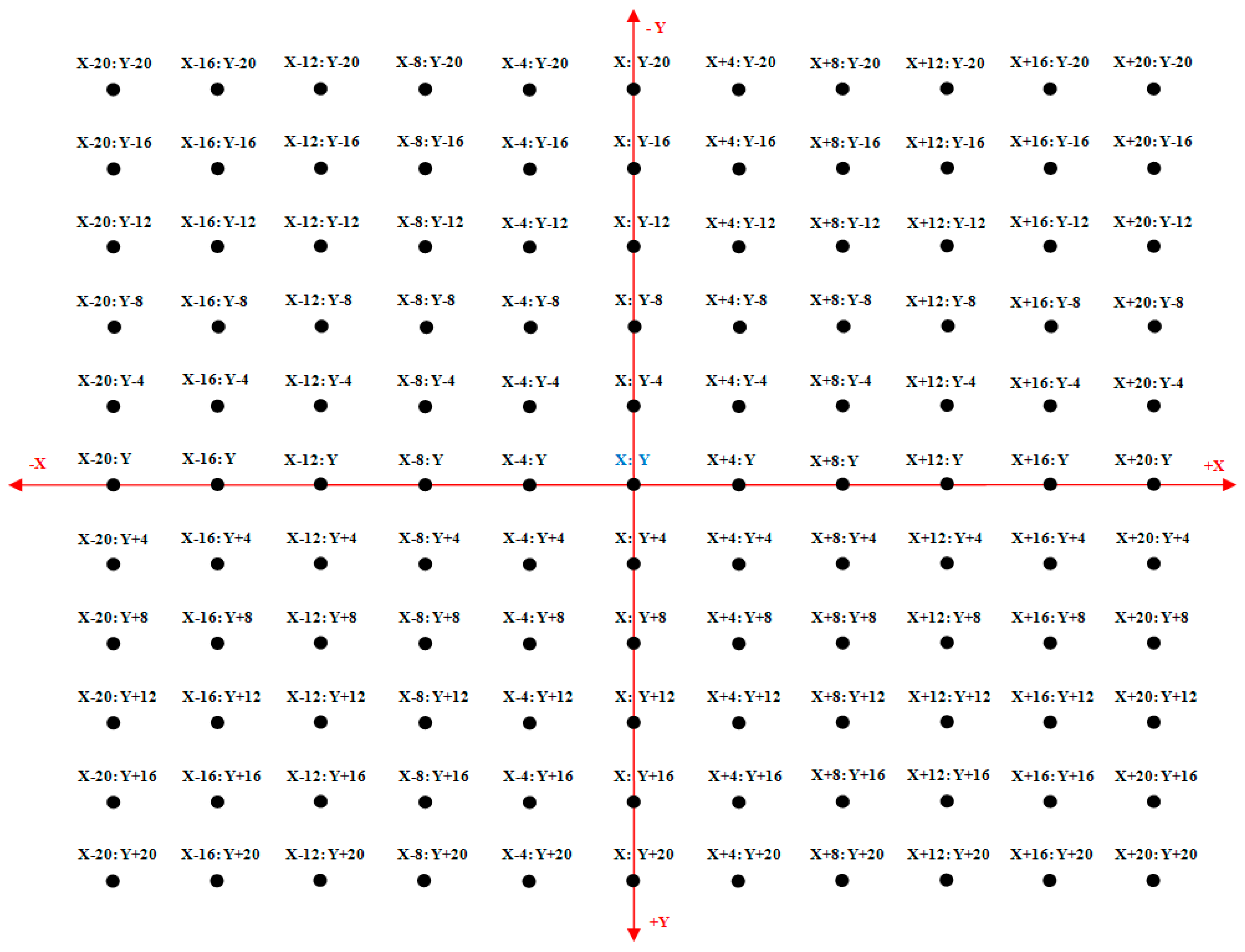
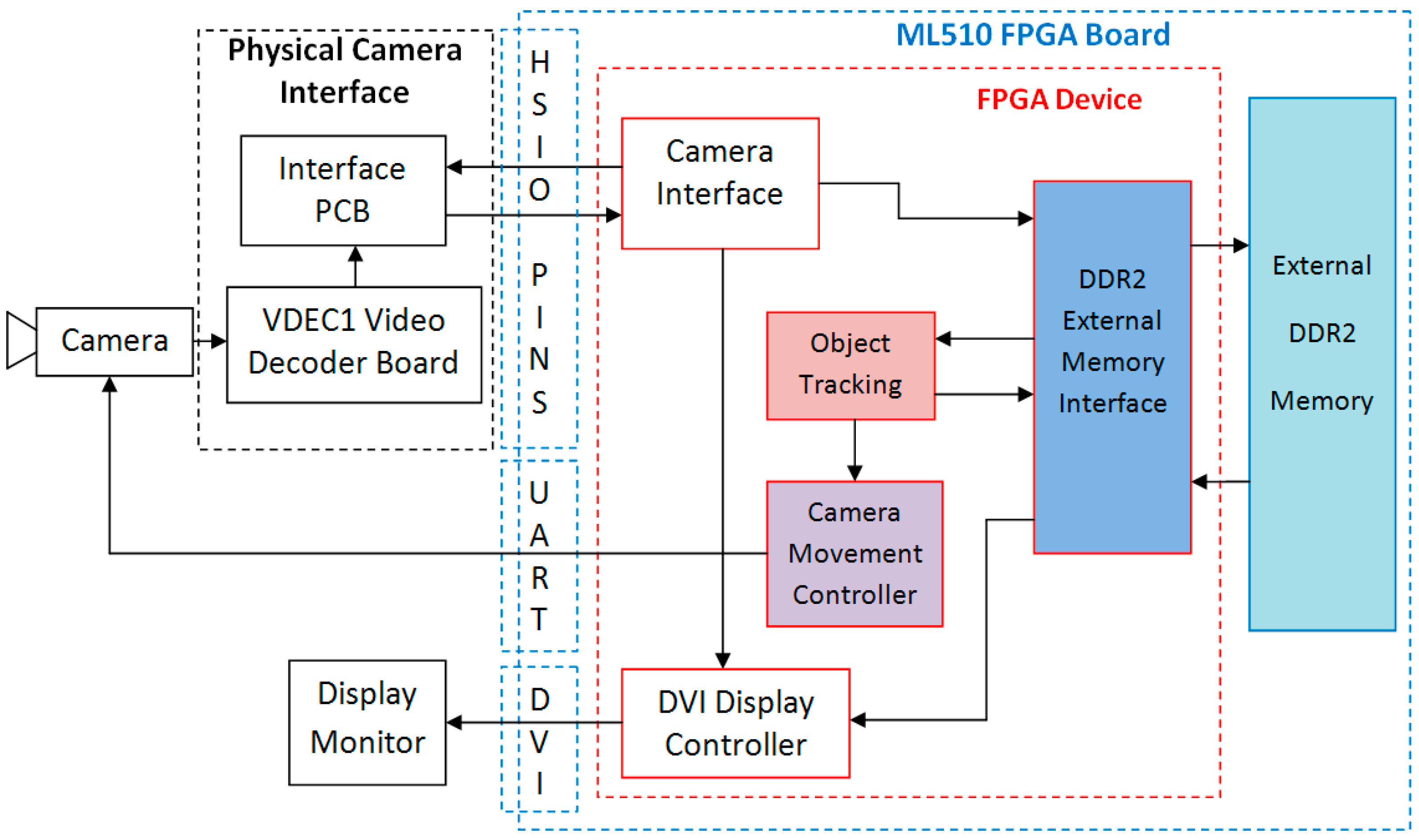
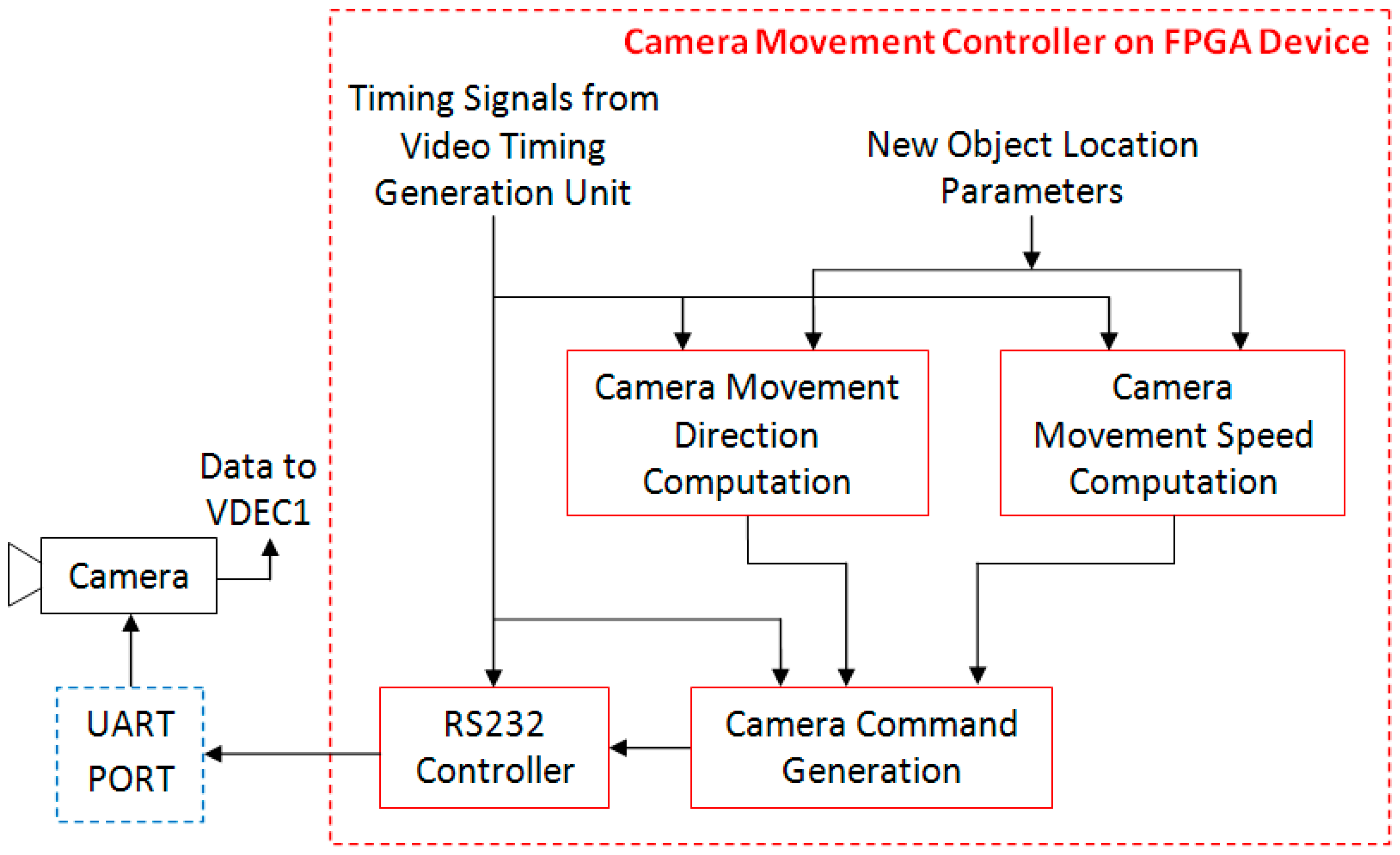
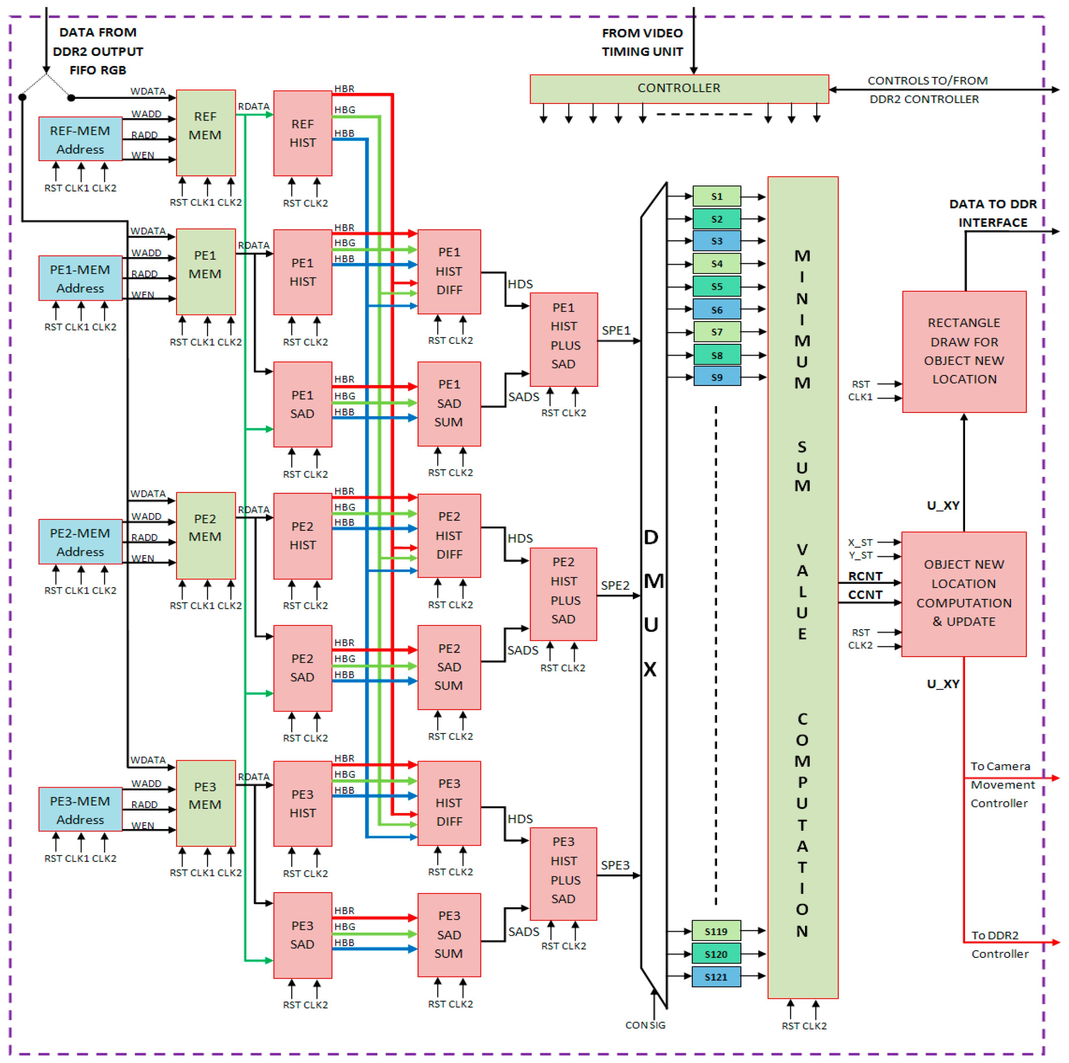
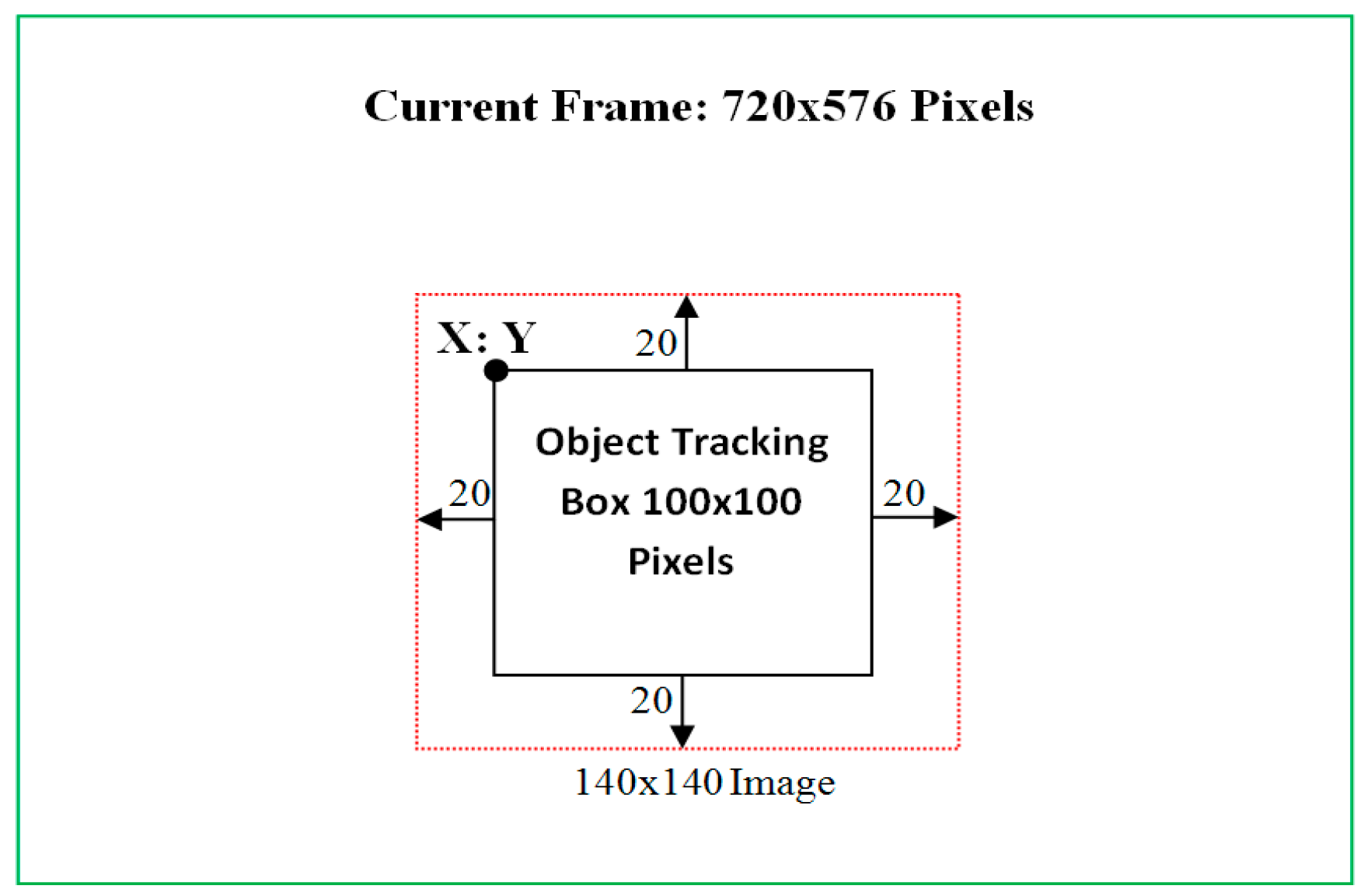
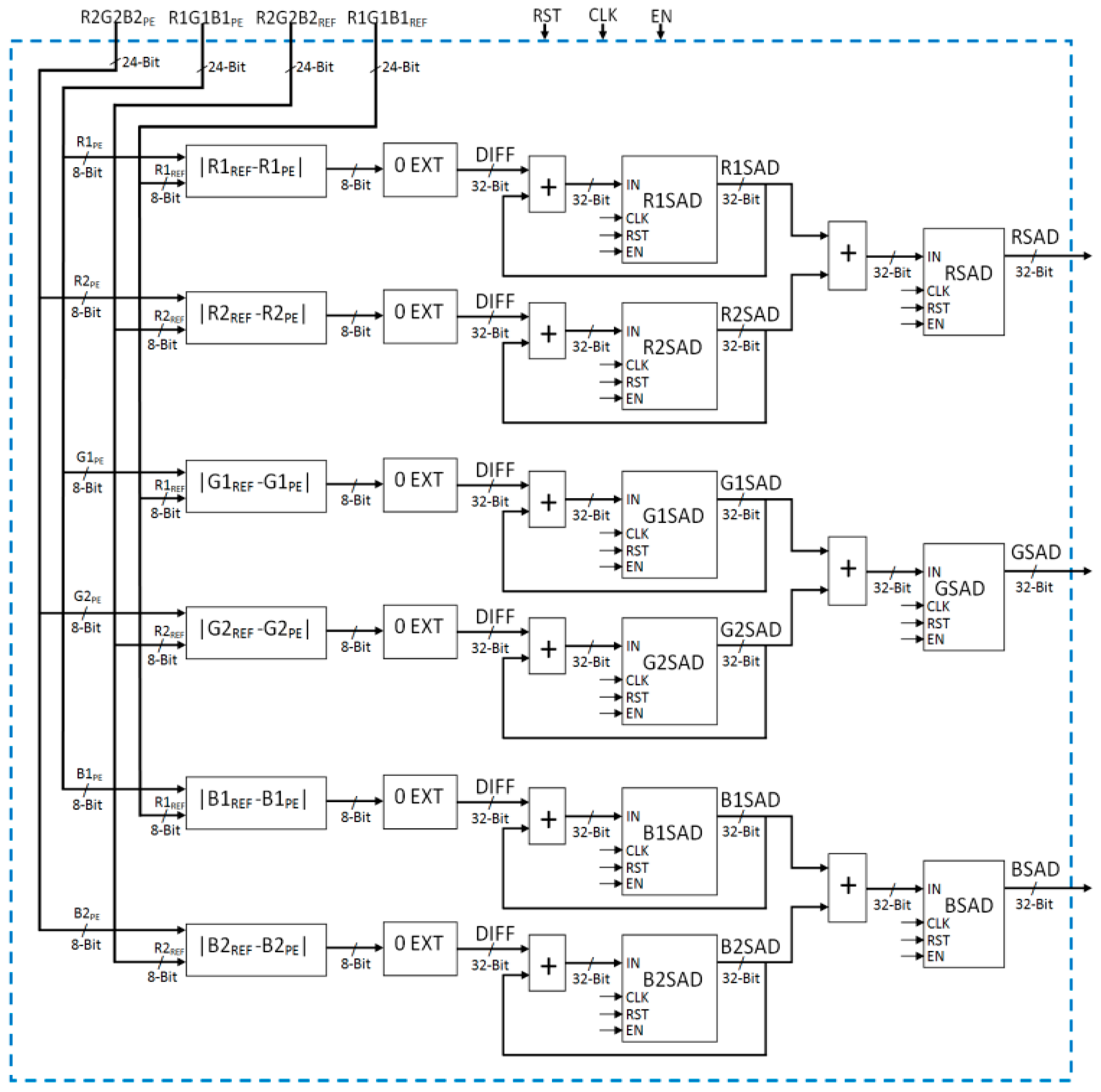
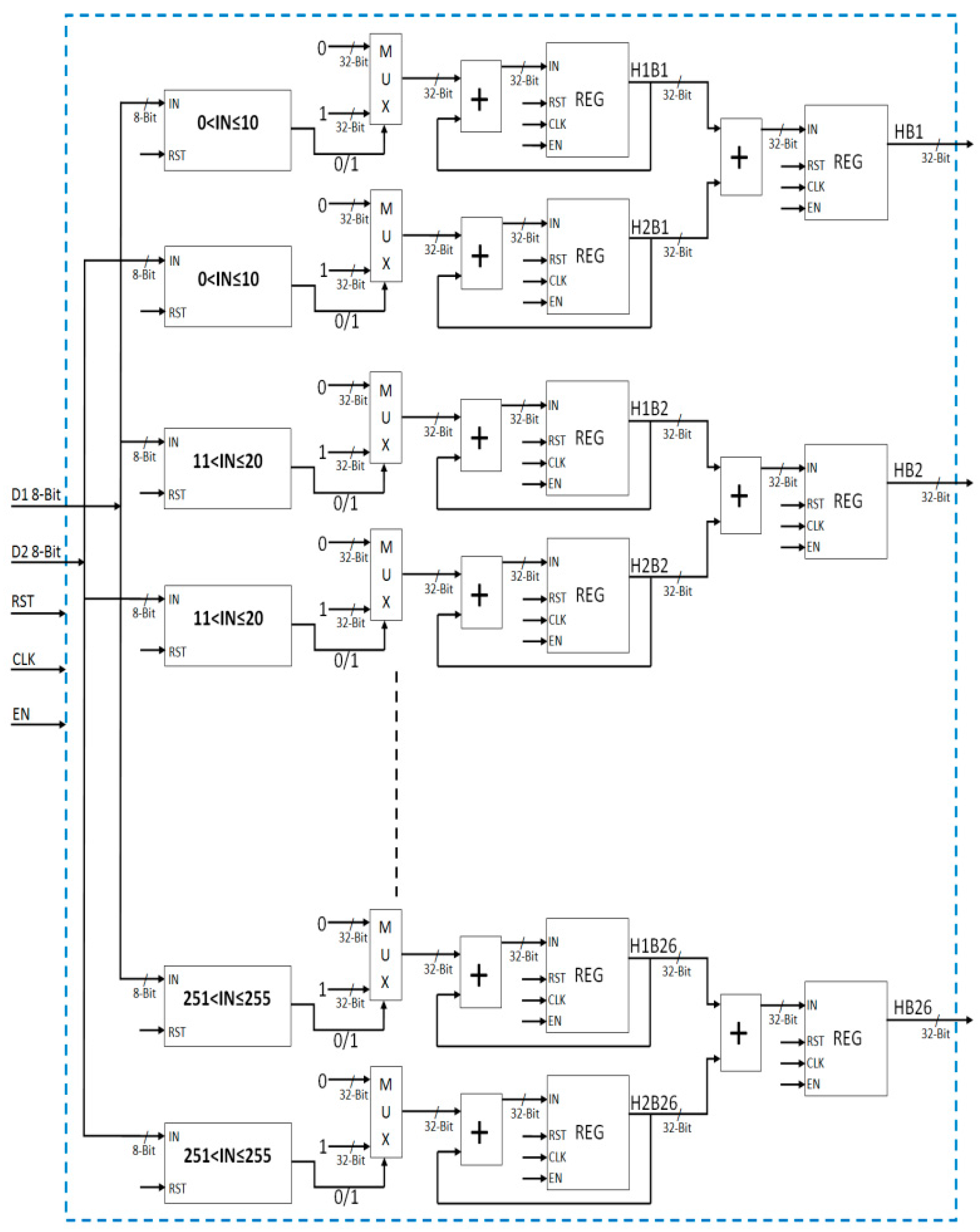
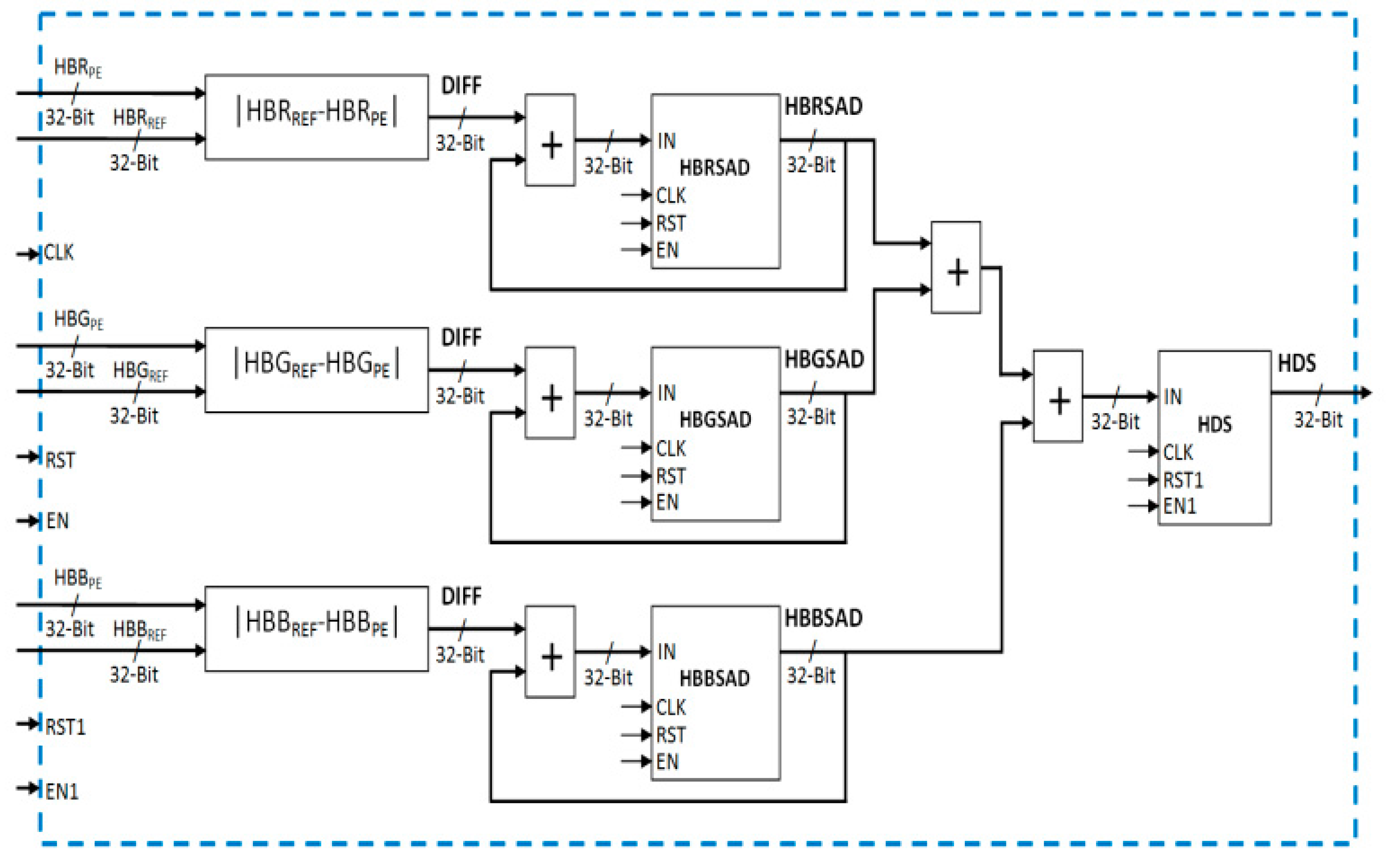
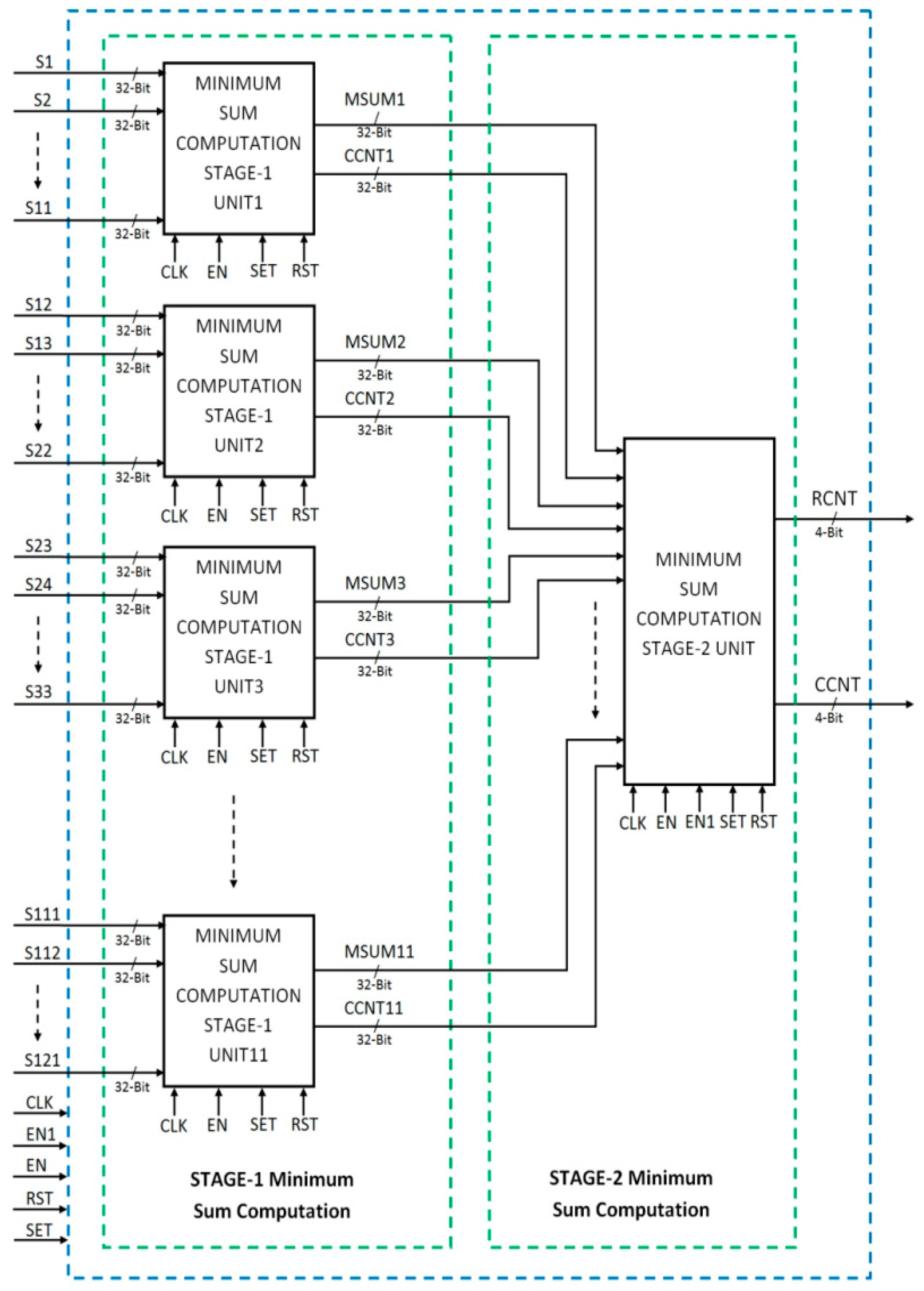
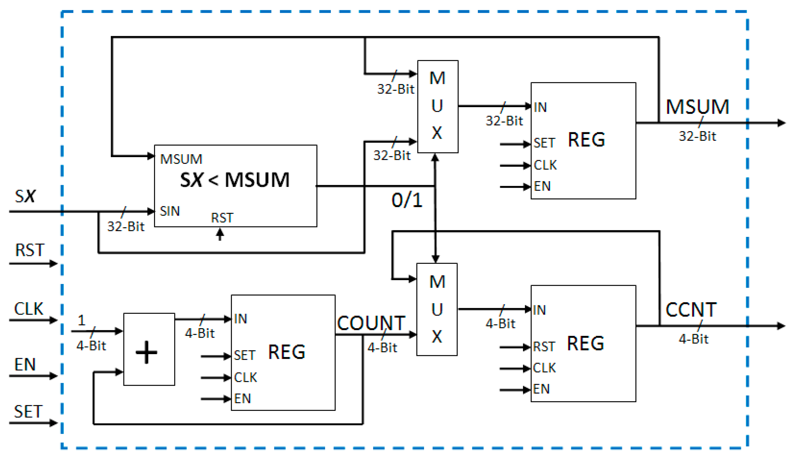
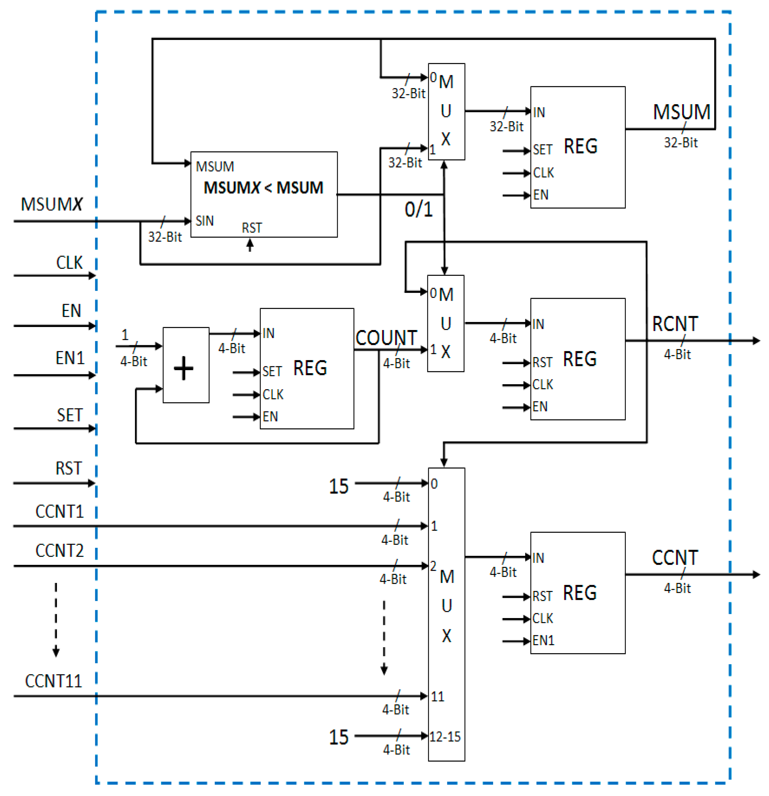
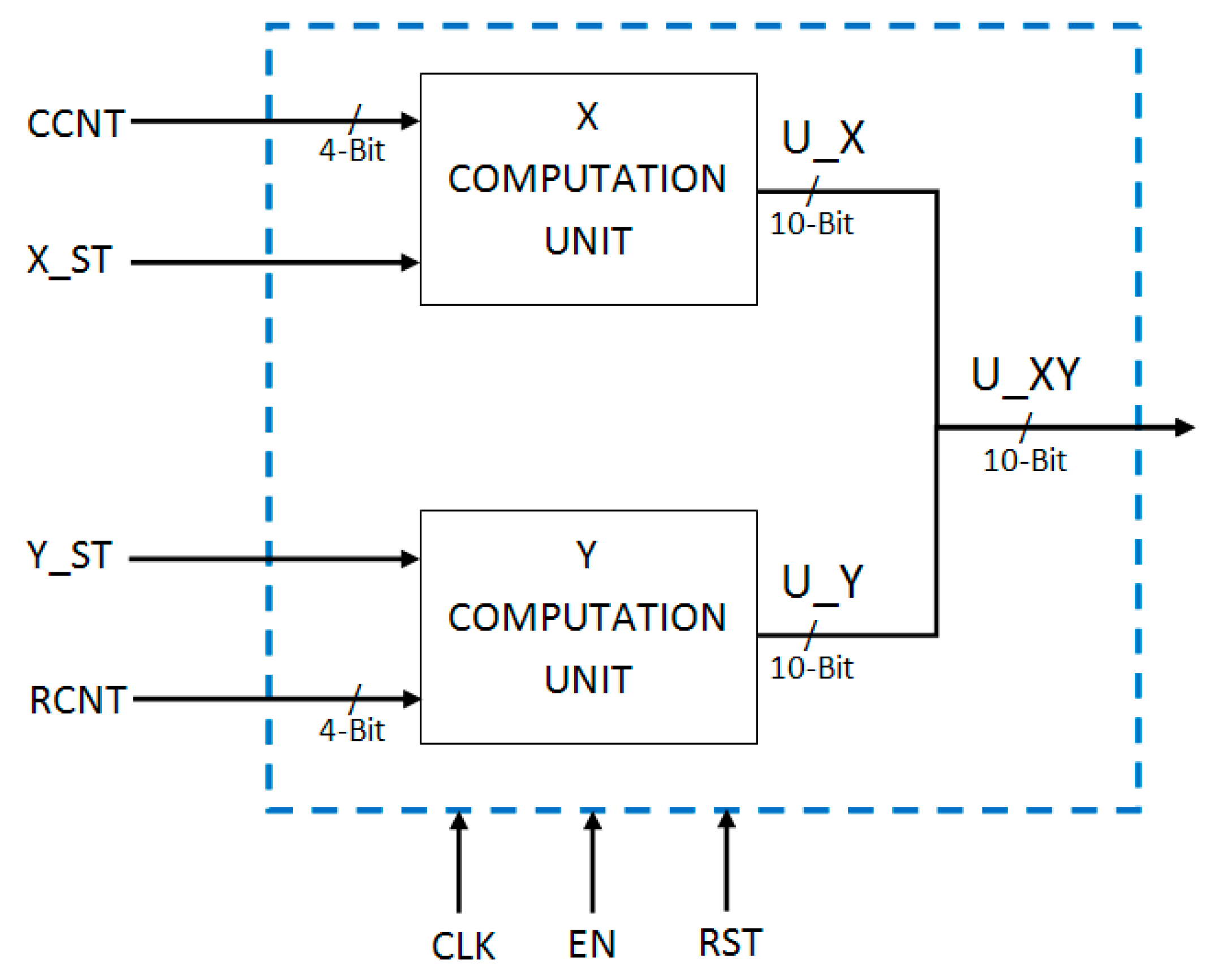
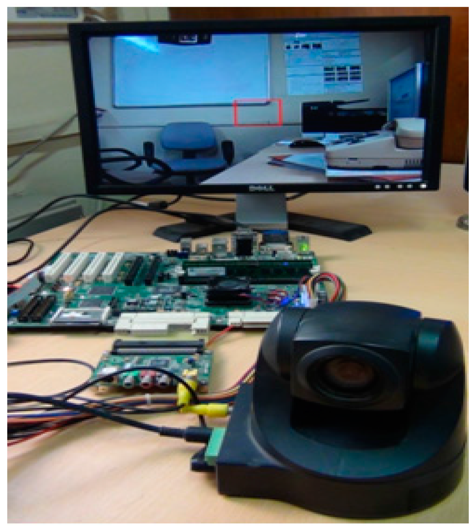
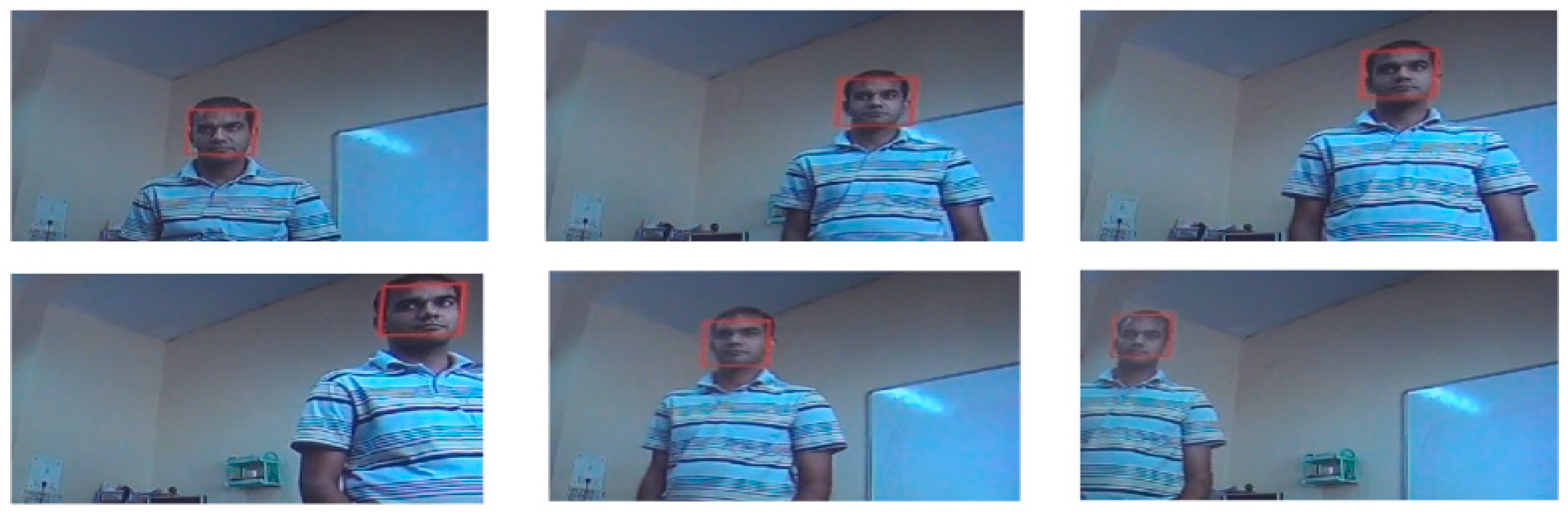
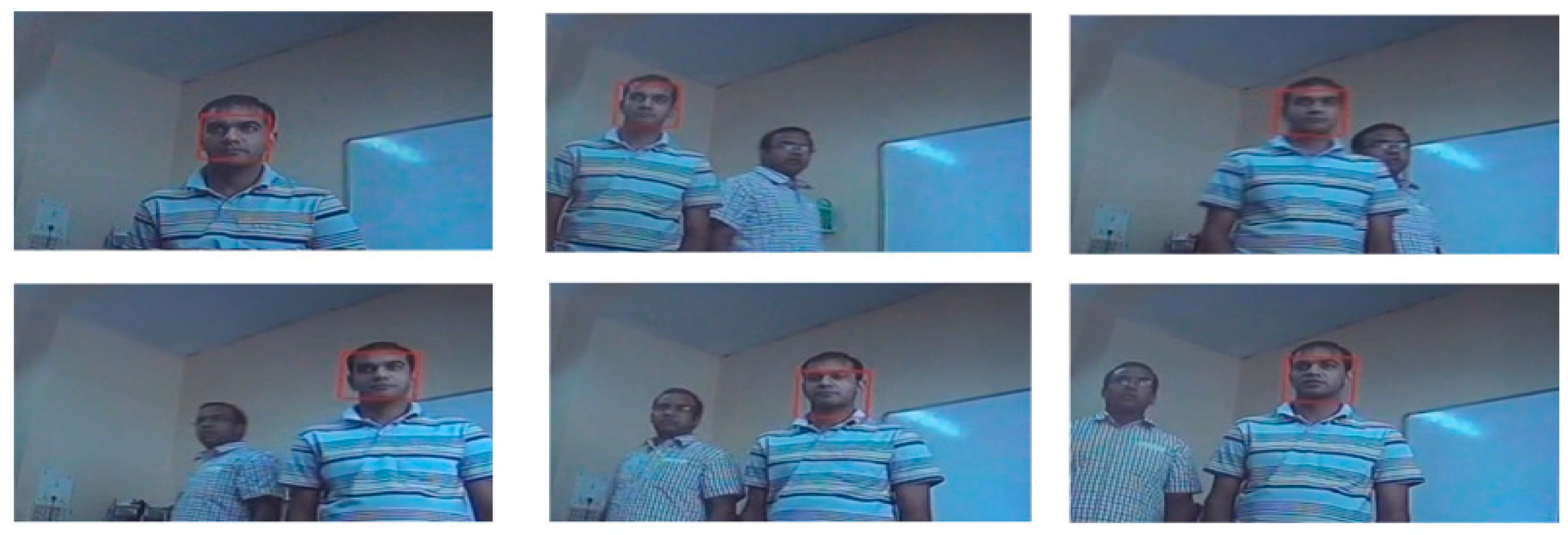
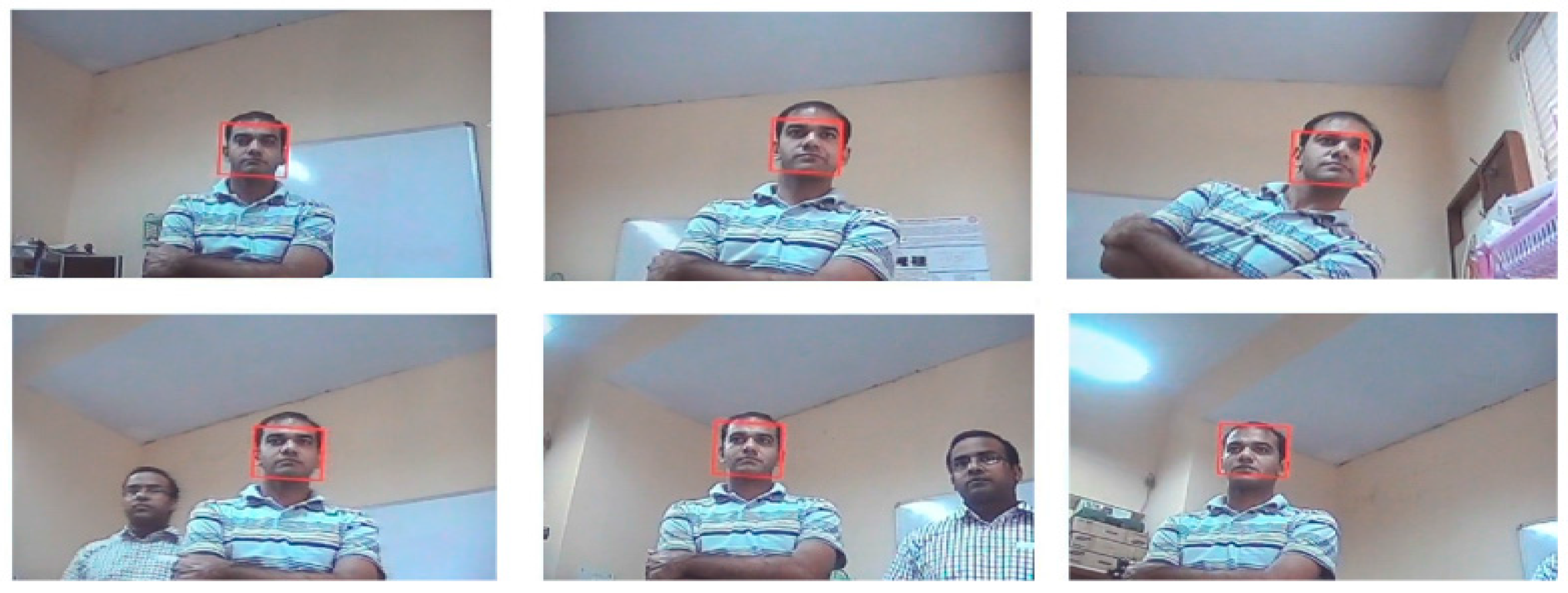
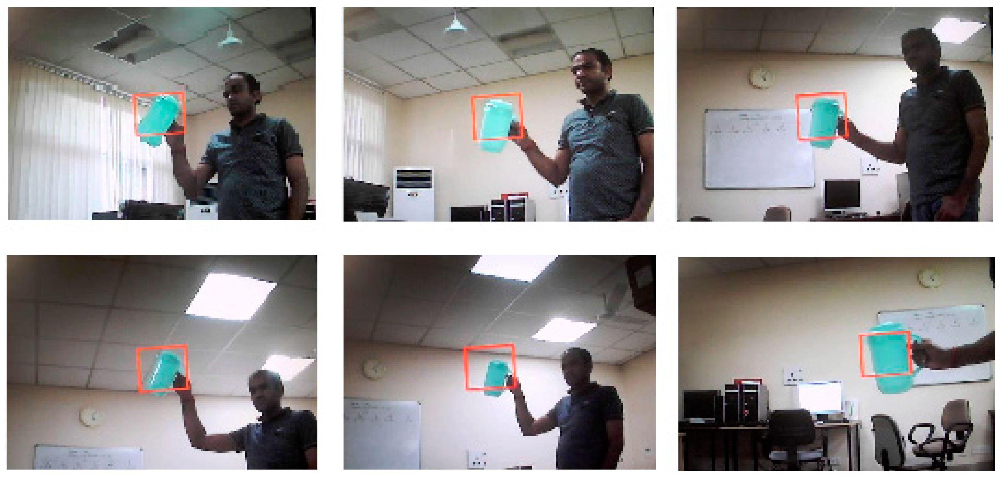
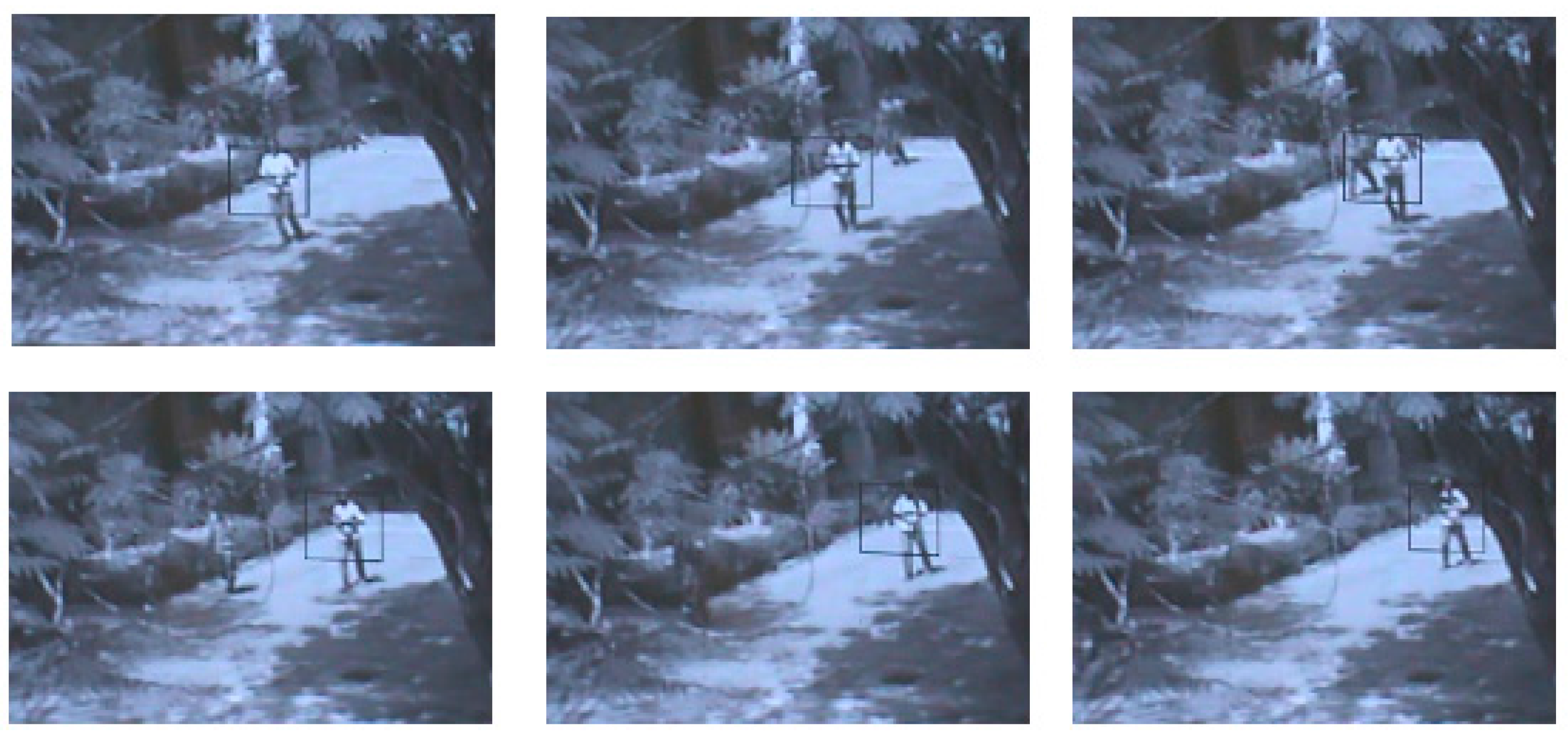
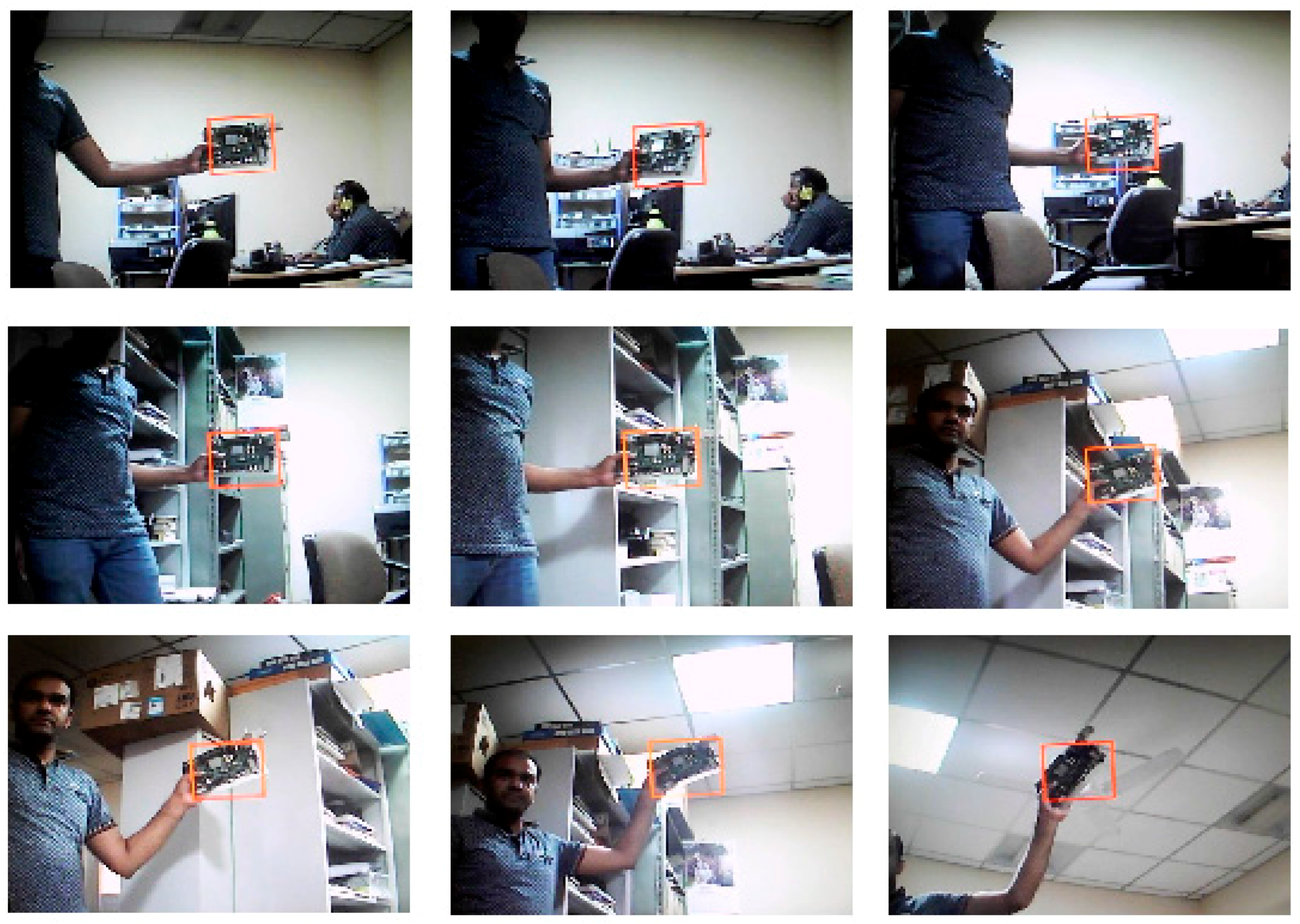
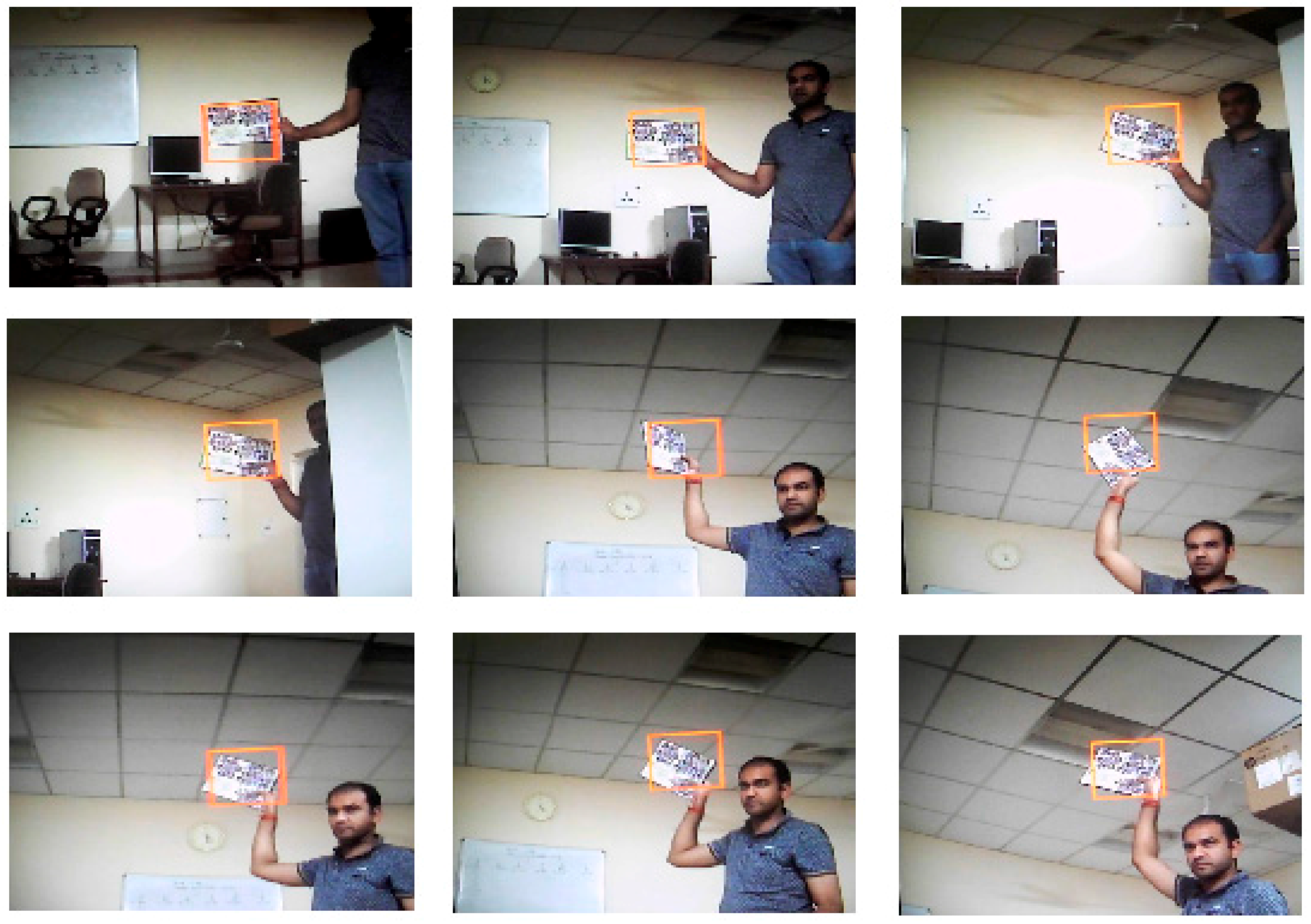
Table 1.
FPGA resource utilization by object tracking architecture and four interfaces.
| Resources | Camera Interface | DVI Display Interface | Camera Movement Controller | DDR2 External Memory Interface | Proposed and Designed Object Tracking Architecture |
|---|---|---|---|---|---|
| Slice Registers | 391 | 79 | 162 | 3609 | 23,174 |
| Slice LUTs | 434 | 101 | 487 | 2568 | 34,157 |
| Route-thrus | 42 | 39 | 48 | 113 | 9033 |
| Occupied Slices | 199 | 33 | 160 | 1616 | 10,426 |
| BRAMs 36K | 3 | 0 | 0 | 16 | 84 |
| Memory (Kb) | 108 | 0 | 0 | 576 | 3024 |
| DSP Slices | 3 | 0 | 0 | 0 | 0 |
| IOs | 16 | 22 | 5 | 255 | 292 |
Table 2.
FPGA resource utilization by complete implementation of object tracking system.
| Resources | Complete System (Object Tracking Architecture + Four Interfaces) | Total Available Resources | Percentage of Utilization |
|---|---|---|---|
| Slice Registers | 27,396 | 81,920 | 33.44% |
| Slice LUTs | 37,715 | 81,920 | 46.04% |
| Route-thrus | 9265 | 163,840 | 5.65% |
| Occupied Slices | 12,414 | 20,840 | 59.56% |
| BRAMs 36K | 103 | 298 | 34.56% |
| Memory (Kb) | 3708 | 10,728 | 34.56% |
| DSP Slices | 3 | 320 | 0.94% |
Table 3.
Performance comparison with existing object tracking implementations.
| Target FPGA Device | Implementation | Video Resolution | Frame Rate (fps) |
|---|---|---|---|
| Virtex5 (xc5fx130t-2ff1738) | Our Implementation | PAL (720 × 576) | 303 |
| Virtex5 (xc5lx110t) | Our Implementation | PAL (720 × 576) | 303 |
| [62] | PAL (720 × 576) | 197 | |
| Virtex4 (xc4vlx200) | Our Implementation | PAL (720 × 576) | 200 |
| [63] | VGA (640 × 480) | 81 | |
| [64] | VGA (640 × 480) | 81 | |
| Virtex-IIPro (xc2pro30) | [49] | QVGA (320 × 240) | 25 |
| Spartan3 (xc3sd100a) | [59] | PAL (720 × 576) | 30 |
Table 4.
Summary of selected parameter values and performance of our object tracking implementation.
Table 4.
Summary of selected parameter values and performance of our object tracking implementation.
| Number of Particles | Tracked Object Size | Number of Histogram Bins in Each R, G and B Color Channel | Video Resolution | Maximum Clock Frequency | Frame Rate (fps) |
|---|---|---|---|---|---|
| 121 | 100 × 100 Pixels | 26 Bins | 720 × 576 | 125.8 MHz | 303 |
© 2017 by the authors. Licensee MDPI, Basel, Switzerland. This article is an open access article distributed under the terms and conditions of the Creative Commons Attribution (CC BY) license (http://creativecommons.org/licenses/by/4.0/).
Share and Cite
MDPI and ACS Style
Singh, S.; Shekhar, C.; Vohra, A. Real-Time FPGA-Based Object Tracker with Automatic Pan-Tilt Features for Smart Video Surveillance Systems. J. Imaging 2017, 3, 18. https://doi.org/10.3390/jimaging3020018
AMA Style
Singh S, Shekhar C, Vohra A. Real-Time FPGA-Based Object Tracker with Automatic Pan-Tilt Features for Smart Video Surveillance Systems. Journal of Imaging. 2017; 3(2):18. https://doi.org/10.3390/jimaging3020018
Chicago/Turabian StyleSingh, Sanjay, Chandra Shekhar, and Anil Vohra. 2017. "Real-Time FPGA-Based Object Tracker with Automatic Pan-Tilt Features for Smart Video Surveillance Systems" Journal of Imaging 3, no. 2: 18. https://doi.org/10.3390/jimaging3020018
Note that from the first issue of 2016, this journal uses article numbers instead of page numbers. See further details here.