Load Transfer of Offshore Open-Ended Pipe Piles Considering the Effect of Soil Plugging

1
School of Civil Engineering, Qingdao University of Technology, Qingdao 266033, China
2
China Postdoctoral research fellow, Hydraulic Engineering Post-Doctoral Scientific Research Station, Zhejiang University, Hangzhou 310058, China
3
Key Laboratory of Offshore Geotechnics and Material of Zhejiang Province, College of Civil Engineering and Architecture, Zhejiang University, Hangzhou 310058, China
4
School of Civil Engineering, Shandong University, Jinan 250061, China
*
Author to whom correspondence should be addressed.
J. Mar. Sci. Eng. 2019, 7(9), 313; https://doi.org/10.3390/jmse7090313
Submission received: 25 July 2019
/
Revised: 30 August 2019
/
Accepted: 30 August 2019
/
Published: 8 September 2019
Abstract
:Open-ended pipe piles have been increasingly used as the foundations for offshore structures. Considering the soil plugging effect, a novel analytical model is proposed in this paper to study the load transfer mechanism of open-ended pipe piles. A trilinear model for the external shaft friction was introduced, while a rigid plastic model was adopted to describe the load transfer at the pile-plug interface. Furthermore, an equilibrium equation of the soil plug was proposed, based on the hypothesis of a trilinear distribution of lateral earth pressure. The pile end resistance was analyzed by dividing it into two parts, i.e., the soil plug and pile annulus, the behaviors of which were described by the double broken line model. A calculation example was carried out to analyze the load transfer properties of the open-ended pipe piles. As a validation, similar load transfer processes of the open-ended pile were also captured in a newly built discrete element method model, mimicking the 100g centrifuge testing conditions.
1. Introduction
In recent years, a large number of offshore structures have been under construction worldwide, such as offshore platforms, pipelines and wind farms. There are also some related theoretical and experimental researches about the responses of offshore structures in a complicated ocean environment [1,2,3,4]. Pipe piles have been generally used as the underlying supporting structures of these structures because of their satisfactory bearing capacity, light weight and outstanding workability [5,6,7,8]. In most cases, open-ended modes are employed to increase the ease of penetration [9,10,11,12,13]. However, during open-ended pile driving, part of the soil will be squeezed into the pipe pile and therefore a soil plug is formed. It is the formation of the soil plug that causes the load transfer of these open-ended pipe piles, rather different from that of closed-ended and solid ones, thus impacting the properties of their bearing capacity [14].
The bearing capacity of an open-ended pile is composed of external skin frictional resistance, annular toe resistance, as well as plug resistance (less of internal frictional resistance and base resistance on the soil plug). Frictional resistance is caused by the relative displacement between pile shaft and soil (soil plug). However, the mobilization mechanisms between external and internal skin frictions are different. During the initial loading, the external skin friction is gradually developed top-down as the pile descends, and the working load at the pile top is completely borne by the external skin friction. At this moment, no settlement occurs for the pile annulus end and no soil is squeezed into the pile pipe, thus the internal skin friction is not mobilized. As the loading increases, the applied load transfers to the soil below the pile annulus. Since the pile shaft has significantly larger rigidity than the soil plug, the soils below the pile annulus experience larger compression than that below the soil plug. This causes few soils to be squeezed into the pile pipe, even though the length of the soil plug keeps constant in most cases, i.e., the pile remains plugged during static testing [1,15,16]. During this stage, internal friction is gradually developed and soil plug resistance increases gradually. This complicated load transfer procedure suggests that the previous load transfer theoretical models [12,17,18], which were derived from the solid pile, is not applicable for an open-ended pile.
Recently, the equilibrium analysis on soil plugs [1,7,14,19,20,21], as well as the experiments in a field and testing chamber [8,10,22,23,24], have improved the understanding of the stress mobilization in the soil plugs of open-ended piles. Nevertheless, there are very few analytical models for an open-ended pipe pile [14,15]. This lack limits the accurate prediction of bearing capacity and settlement for open-ended piles by a theoretical approach. Therefore, taking the soil plugging effect into consideration, and using load transfer as the analytical method, this paper develops a theoretical approach for calculating the load transfer of open-ended pipe piles. A calculation example is presented to exhibit the load transfer characteristic of an open-ended pile subjected to vertical loading and its difference compared to a closed-ended pile. As a validation, a numerical two-dimensional discrete element method (DEM) model using PFC software which was developed by the ITASCA consulting group was built to reveal this load transfer process by applying axial loading to an open-ended pile jacked into sandy soil.
2. Load Transfer Model of Open-Ended Pipe Piles
2.1. Computational Assumptions
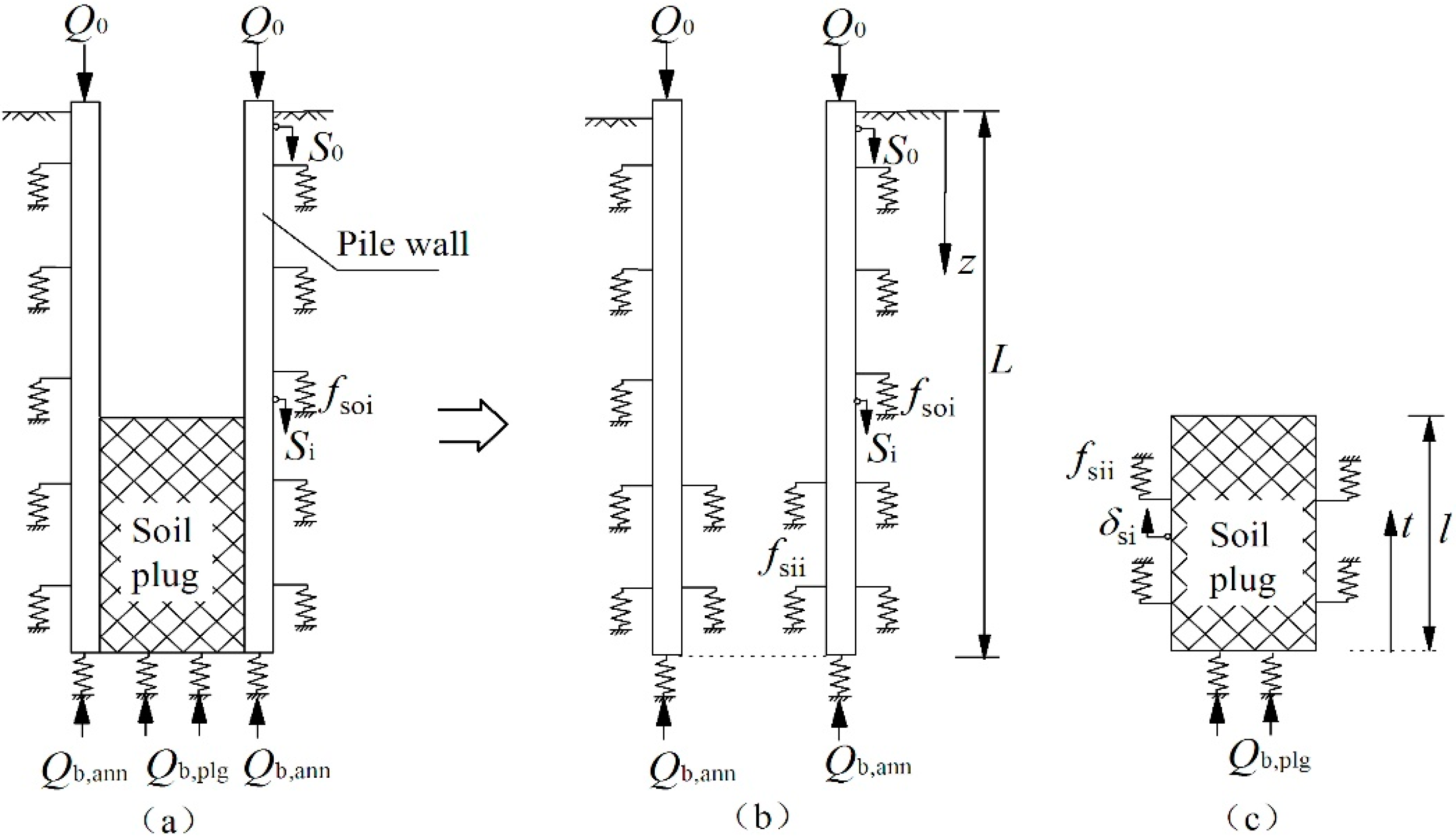
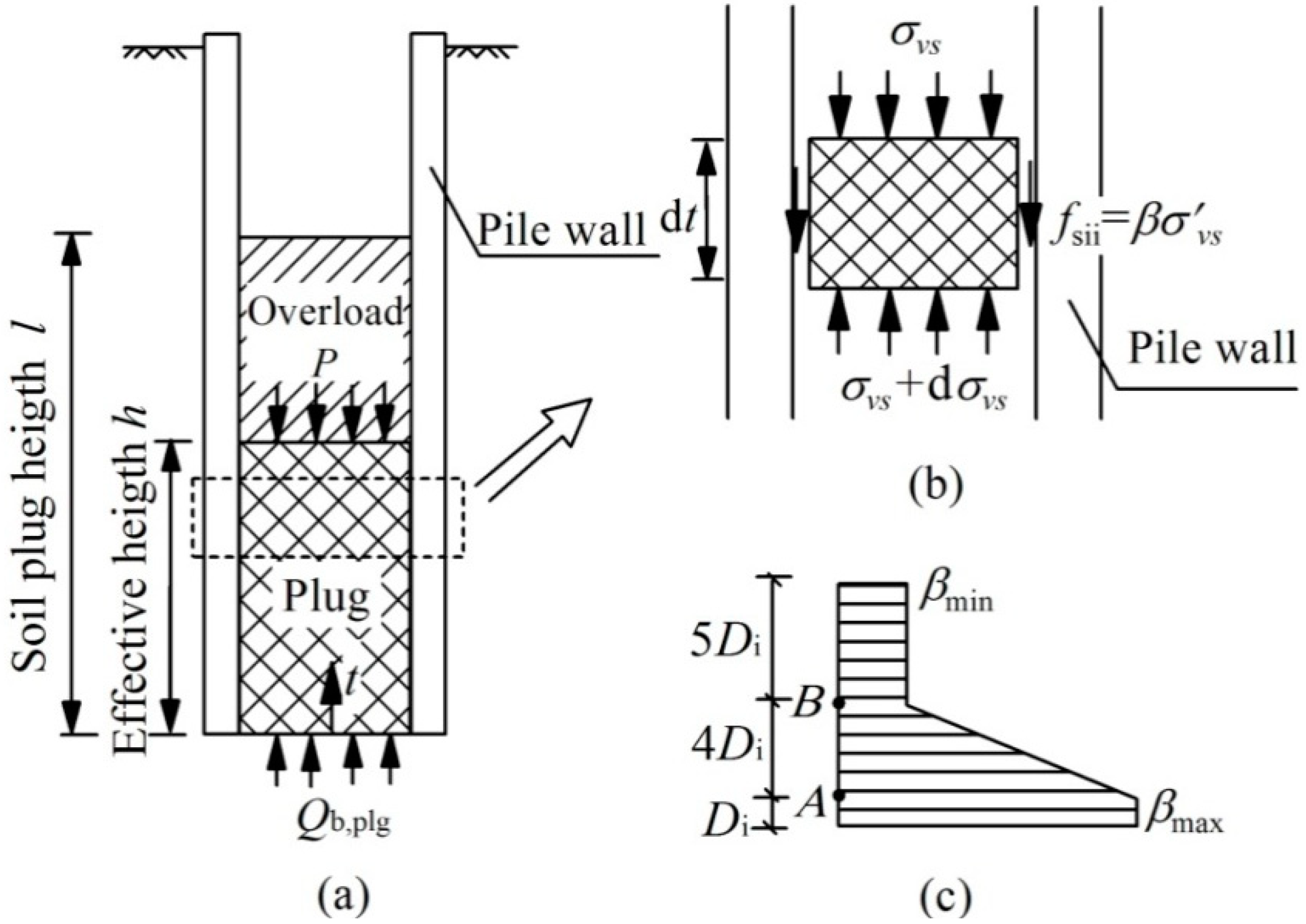
As soil plug is a major factor that affects the development of bearing capacity of open-ended pipe piles, with the interactions between the soil plug and pile annulus being crucial. In order to simplify the calculations, the effect of the pile annulus and internal soil plug was considered separately. The open-ended pipe pile was defined as a kind of “pile-in-pile” system, i.e., the pile annulus as the “outer pile” (Figure 1b) and the soil plug as the “inner pile” (Figure 1c). Thus, the pile annulus and soil plug can be analyzed separately. At the same time, they experienced interactive coupling and together constrained the development of the bearing capacity of the pipe pile. The external skin frictional resistance of the inner pile (soil plug) was the internal skin friction of the outer pile (pile annulus).
In these calculations, it was assumed that the load at annulus end Qb,ann transferred through the pile annulus (outer pile), and the load at the soil plug end Qb,plg transferred through the soil plug and then induced the internal skin friction fsi. The derivation was based on the following assumptions: (a) The material behavior of the pile shaft was assumed to be linearly elastic under vertical loading; (b) pile tip settlement was only induced by the loads on the pile tip; (c) the soil was homogeneous. The assumptions (a) and (b) are consistent of those in the previous load transfer theoretical models for solid pile [17,18,25]. Assumption (c) was just used to simplify this analytical model.
According to the force equilibrium of a pile unit, the basic differential equation for load transfer can be written as [25], which was applicable to the external pile annulus (outer pile) and soil plug (inner pile), as shown in Figure 1.
where Ep is the elastic modulus of pile (kPa); Ap is the area of cross-section of pile (m2); z is the depth from ground surface; dz is the unit change of depth; S(z) is the relative displacement of pile to surrounding soil medium (m); fs(z) is the unit side friction (kPa), which is the friction of the soil surrounding the pile annulus and the annulus soil plug for the outer pile and inner pile, respectively, in the herein “pile-in-pile” analytical model; U is the circumference of the pile cross-section (m). It should be noted that compared to the resistances of soils, the weight of the hollow pipe pile was much smaller and therefore its contribution to the force equilibrium was ignored for simplicity.
The relation between the axial force of pile P(z), unit side friction fs(z) and the relative displacement of pile to surrounding medium S(z) was as follows [25]:
where r0 is the radius of pile. It should be noted that the above equations were common for all the piles. However, the parameters were valued respectively for the external pile annulus (outer pile) and soil plug (inner pile) in the current model of an open-ended pile.
2.2. Load Transfer Model of Outside Pile Annulus
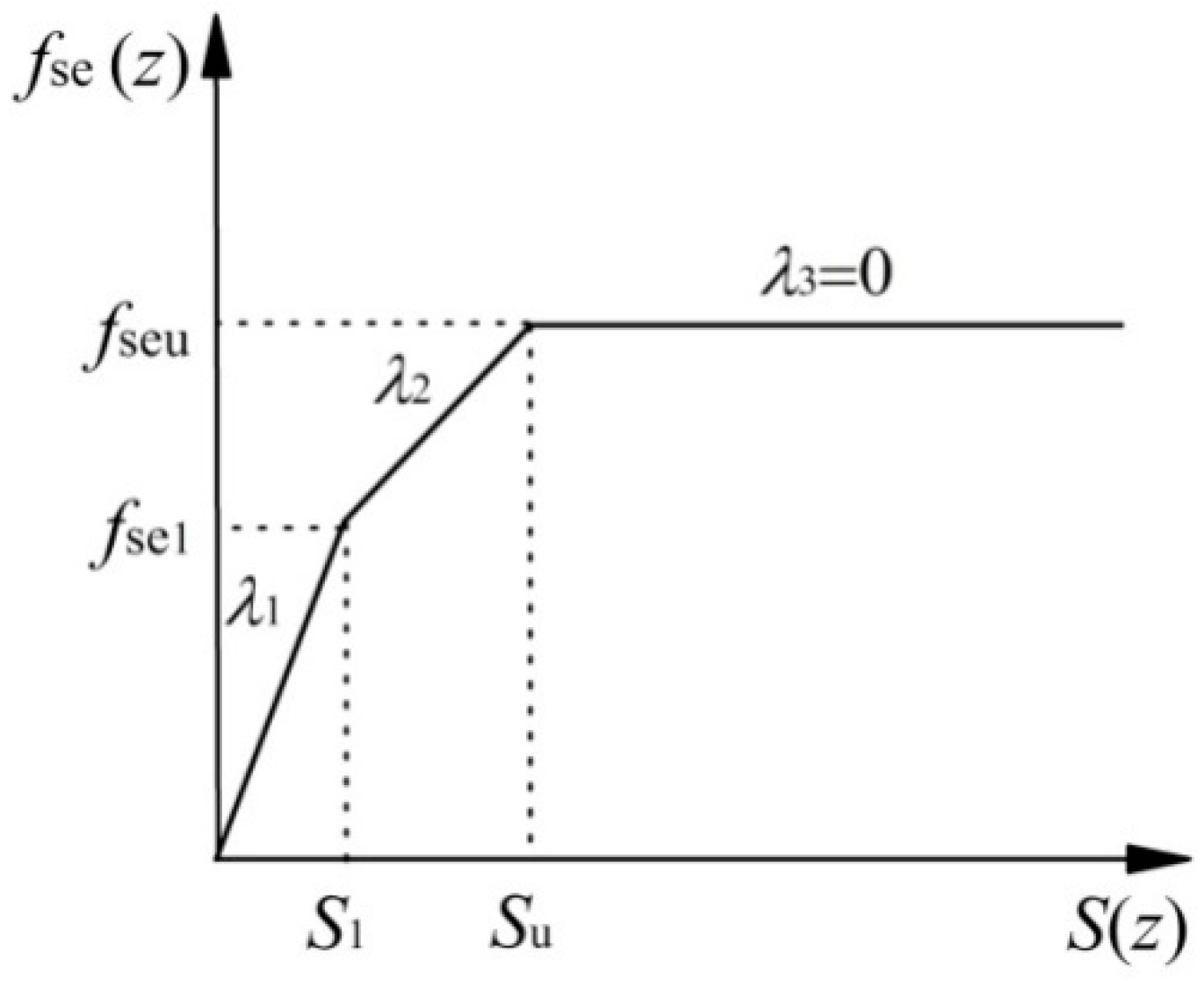
A trilinear model is used for the load transfer of the pile annulus and surrounding soil, as shown in Figure 2, and the load transfer function was expressed in Equation (3), as follows:
where fse(z) is the external skin friction of pipe pile (Pa); S(z) is the relative displacement of pile annulus to surrounding soil (m), which is descending in amount under the assumption of no vertical movement of the surrounding soil; λ1 and λ2 are the coefficients of shearing rigidity of the surrounding soil in the elastic and plastic stages, respectively (Pa/m); S1 is the limit displacement at the end of the elastic stage (m); Su is the limit displacement when side friction achieves its maximum at the end of the plastic stage (m). To determine load transfer function, four parameters are needed-λ1, λ2, S1 (or fse1) and Su (or fseu). Furthermore, it is assumed that the coefficients of shearing rigidity in elastic and plastic stage λ1 and λ2 are only dependent on the material of pile and soil, but independent of depths. Hence they remain the same in homogeneous soil. Let fse1 = ηfseu = ηkz (η is a constant). Boundary and limit displacements were obtained as follows [25]:
Parameter k is the stiffness coefficient of shaft friction along depth (Pa/m). The values of λ1, λ2 and η can be obtained from field measurements. λ1 can also be approximated using a close-theoretical solution by the shearing displacement method [17] as follows:
where ζ = ln (rm/r0), rm = 2.5L (1 − υs); Gs is the shearing modulus of the surrounding soil; r0 is pile radius; υs is the Poisson’s ratio of the surrounding soil; L is the pile length. The limit side friction fseu is approximated to increase linearly with depth [17], which can be expressed using the β-method:
where γ′ is the effective unit weight of the surrounding soil (kN/m3); K is the lateral pressure coefficient of surrounding soil; δ is the friction angle between the pile annulus and surrounding soil (°).
For the discussions on the values of parameters K and δ of the outside pile annulus, please refer to the author’s previous work [26], in which the pile-soil friction angle δ is 0.9φ′ (where φ′ is the internal friction angle of soil). As for the value of external lateral pressure coefficient K, we believe it is closely related to the amount of soil compaction of the open-ended pipe piles [27,28], which can be directly reflected by the soil plug length rate (PLR). PLR is defined as the ratio of the soil plug length to the penetration depth at the completion of pile installation. Following the work by Yu and Zhang [28], a linear model was used to express how the coefficient K varies with PLR
where PLR, if not known, for an open-ended steel pile may be estimated by an empirical relationship proposed by Yu and Zhang [28].
where Di is the inside radius of the pile. For normally consolidated sandy soil, the relationship between the at-rest earth pressure coefficient K0 and the frictional angle of soil φ′ was as follows:
2.3. Load Transfer Model inside the Pile Annulus
There is no research to date on the load transfer model for the inner side of pile annulus. Randolph [29] thought that the relative displacement required by the inner side of a steel pile to develop the internal skin friction is only 0.2%~0.5% of the pile radius. Therefore, Randolph et al. [6] neglected this relative displacement in his theoretical reasoning, assuming a rigidity model for the development of internal skin frictional resistance. A rigidity plastic expression was also introduced here to describe the load transfer at the pile-plug interface:
where fsi is the unit internal friction of the open-ended pile; Ks is the lateral pressure coefficient of the soil plug; is the effective vertical stress at various height t, as shown in Figure 1c; δi is the friction angle between the soil plug and the inner side of the pile annulus. There is already research showing that the shearing failure plane of the inner side of the annulus occurs inside soil [30]. Hence, if the change in density of the compacted soil plug is neglected, the value of i can be approximated by the friction angle of the soil outside pile. Model tests [31,32,33] and results of numerical analysis [34] showed that, because of the existence of “soil arching effect”, the lateral pressure coefficient of the inner side of pile is greater than that of the outer side, achieving a maximum value between 1 to 2 radius in the vicinity of pile end, as shown in Figure 3. It was expressed as a trilinear model, as shown in Figure 3 and Equation (12).
where h is the effective height of the soil plug; Ksmax and Ksmin are the maximum and minimum lateral pressure coefficients of the soil plug within the effective height.
De Nicola and Randolph [33] suggested that for sandy soil, Ksmax can be expressed as a function of soil relative density Dr (in %), i.e., Ksmax = Dr/100. Lehane and Gavin [23] showed in their research that Ksmax can be as high as 1.3, and Ksmin as low as 0.3. The latter is the value for Ksmin in our computation, but Ksmax is not a constant and is related closely to the plug length ratio (PLR) [28], as expressed in the exponential function below:
2.4. Load Transfer Model for Pile Tip
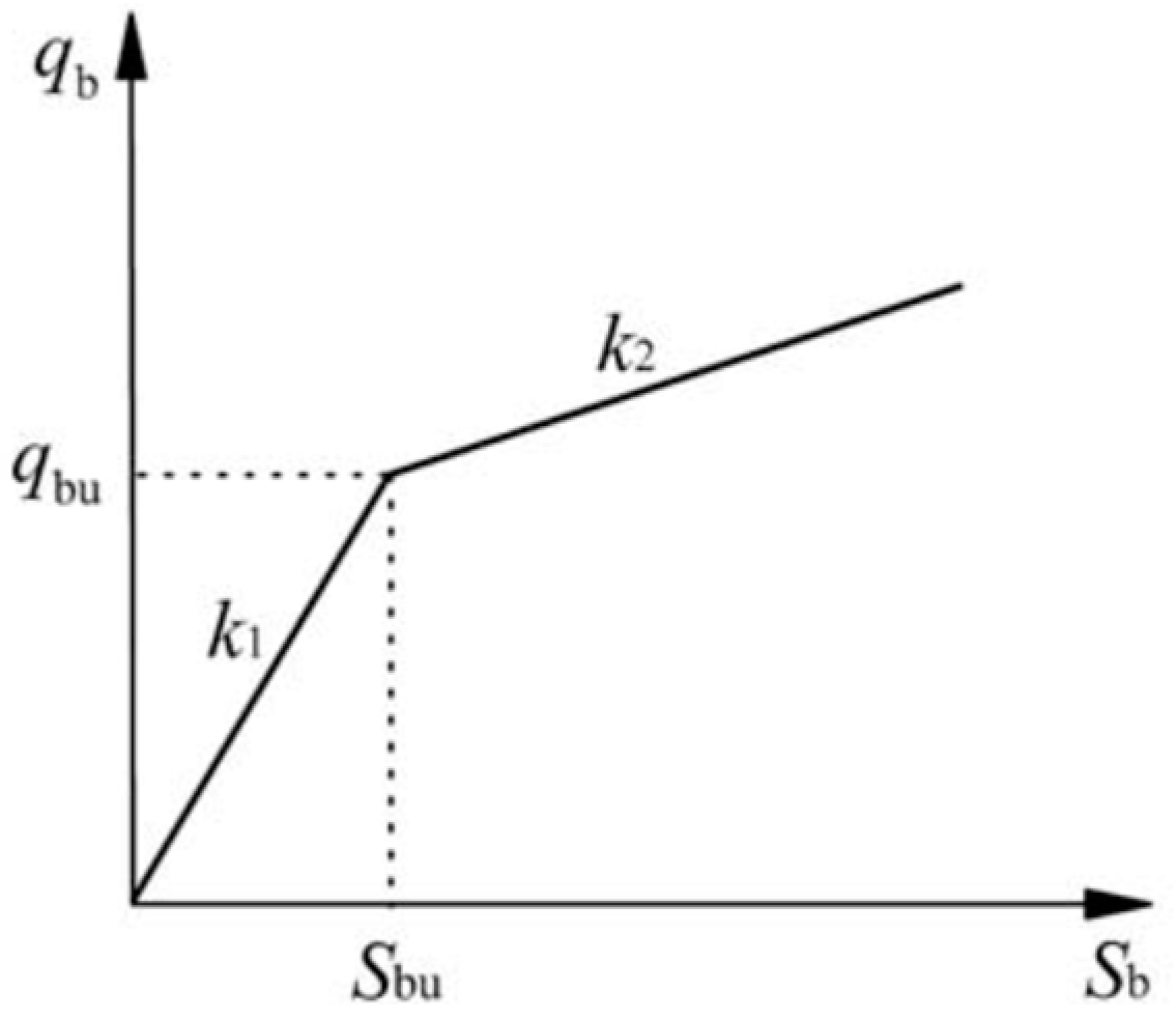
Neglecting the change in properties of soil under the pile tip, the same double broken line model (Figure 4) was used to describe the load transfer of the annulus end and soil plug end, which was expressed as follows [25]:
where qb is the unit vertical stress at pile end(Pa); k1 and k2 are the normal rigidity coefficients in the elastic stage and plastic stage, respectively (Pa/m); Sb is the settlement of the pile end (m); Sbu is the limit displacement between the elastic and plastic stages (m).
k1 can be calculated as follows [17]:
where Gb and υb are the shearing modulus and Poisson’s ratio of the soil below the pile annulus.
k2 can be implied from the load-settlement curve of a single pile. Under a large load, the load-settlement curve remained a straight line, which indicated that the sliding regime of the surrounding soil had expanded to the whole range of the pile shaft, causing the total frictional resistance to stop increasing, with the working load P0 at the pile head being completely borne by pile end resistance. The settlement of the pile end was the result of subtracting the compaction amount of pile shaft ΔS from the descending amount of pile head S0. When the whole pile shaft is in sliding stage, the compaction amount can be solved as follows:
Hence, substituting the three quantities gives k2:
where kt = ΔP0/ΔS0 is the slope of the steep dipping section of the load-settlement curve; Ep and Ap are the elastic modulus and cross-section area of the pile, respectively.
3. Load Transfer Analysis on Open-Ended Pipe Piles
3.1. Load Transfer Analysis outside Pile Annulus
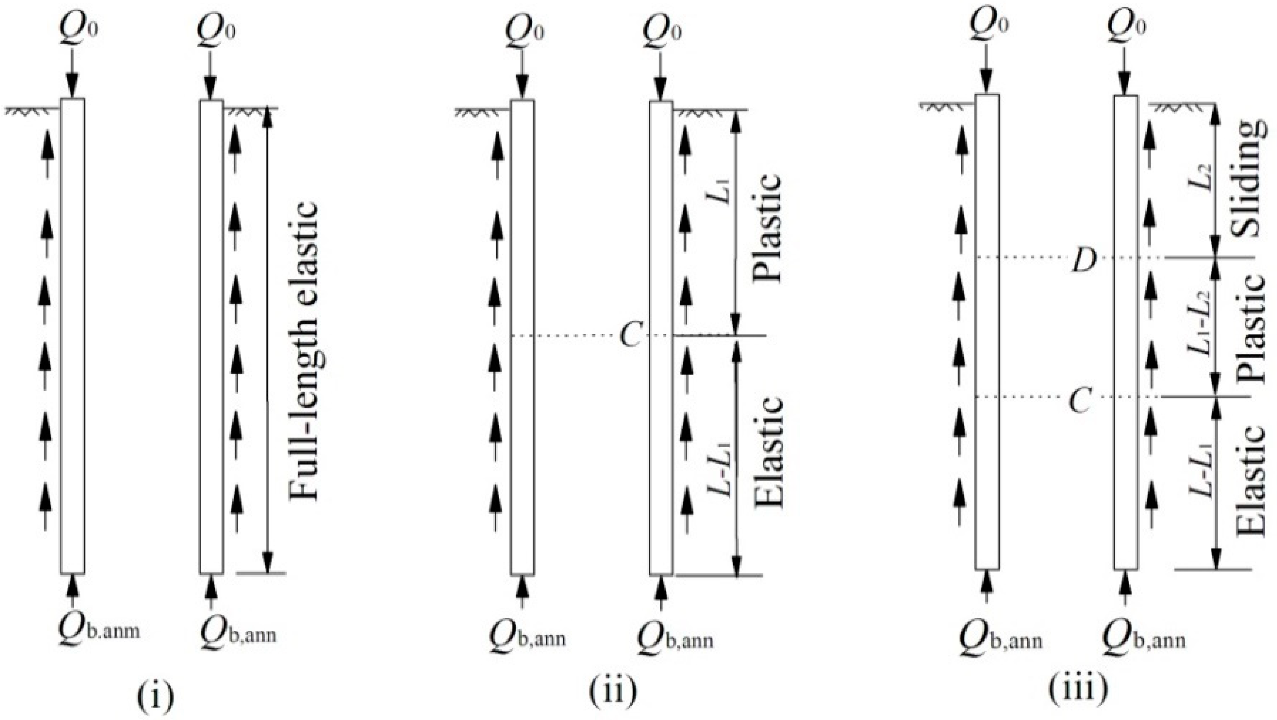
With the settlement of the pile, the friction offered by the pile annulus was mobilized generally. A trilinear load transfer model was applied. The pile-soil interface had three states: (i) elastic stage, (ii) plastic stage, (iii) sliding stage, as illustrated in Figure 5 below.
(1) All surrounding soil in the elastic load transfer stage.
When the working load at a single pile head was small, the settlement of the pile shaft was small, and the surrounding soil was in a full-length elastic state. From the load transfer trilinear model (Figure 2) and basic function (Equation (3)), the load transfer function and the boundary conditions were derived as follows [25]:
Solving the above equations to get
where
(2) Part of the surrounding soil in the elastic stage
As the load at pile head increased, settlement increased as well. When the settlement of pile head met the condition S0 > S1(0), the surrounding soil gradually moved top-down into the plastic stage. Let the load and settlement at cross-section C be Pc and Sc, respectively. Then, for the pile shaft in the plastic stage, the load transfer differential equation and boundary conditions are as follows:
Solving the above equations to get
(3) Part of the surrounding soil in the sliding stage
When the descending amount of pile head met the condition S0 > Su(0), the surrounding soil gradually moved top-down into the sliding stage. The differential equation for sliding stage was as follows:
Solving the above equations to get
where
3.2. Load Transfer Analysis inside the Pile Annulus
During loading, the water in the soil plug gradually drained out, and the elastic modulus Es of the soil plug changed accordingly, yet changing laws are difficult to determine. Hence, the basic load transfer function was hardly applicable. On the other hand, the load transfer between the pile internal skin and the soil plug confirmed the rigidity-plasticity model, i.e., the development of internal skin friction was not affected by relative displacement. Therefore, neither soil plug compaction nor relative displacement needed to be taken into consideration, but only the force balance of the soil plug.
The part of the soil plug above effective height h was treated as overload. The force analysis of the soil plug unit is shown in Figure 6b, and coordinate t (the upwards distance from pile end) in Figure 6a. Hence, the basic expression for the equilibrium equation based on effective stress was as follows:
where β can be expressed using Equations (11) and (12). Since the side pressure coefficient was modelled by a trilinear function, as seen in Figure 6c, the solutions to the equilibrium equation of the soil plug have also been split into three sections as well.
(1) 0 ≤ t < Di
With the equilibrium equation of the soil plug becoming
Considering boundary conditions when x = 0, = qb,plg and denoting gave the vertical effective stress at various heights:
where qb,plg is the vertical stress at soil plug end.
(2) Di ≤ t < 5Di
The equilibrium function for the soil plug was
The function above has no analytic solutions. Now let , , and consider boundary conditions t = Di, σ′v = σ′vsA, where σ′vsA can be obtained by substituting t = Di into Equation (33). Hence, the vertical effective stress of soil plug can be expressed as follows:
where
where erf is the Gaussian error function.
(3) 5Di ≤ t < 10Di
The equilibrium function of the soil plug was
where the parameters σ′vs, Di and are the effective vertical stress, inside radius of the pile and pile-plug friction angle, respectively. Let , and consider boundary conditions x = 5Di, σ′vs = σ′vsB, where σ′vsB can be obtained by substituting t = 5Di into Equation (35). Hence the vertical effective stress for this section was expressed as follows:
The part of soil plug above the effective height can be treated as over-load. Solving the equation below obtains t, which is actually the effective height
The vertical stress at soil plug end qs,plg depended on the settlement of soil below the soil plug end Sb,plg, but Sb,plg is not equal to the settlement of pile annulus end Sb,ann. In order to stimulate the friction on the inner side of the annulus, there must be relative displacement between the soil plug and pile wall, which means that a volume of soil will be squeezed into the pile, i.e., Sb,plg is less than Sb,ann. To determine Sb,plg, the loading mechanic process can be considered as an extension of pile driving at its ending moment. Therefore, the final filing ratio (FFR) of the soil plug, which was defined as the ratio between the increment of the soil plug length and the increment of pile penetration depth over the final stages of pile installation, was adopted here. Then, the relative displacement at the soil plug end w0, and descending amount of the soil below the soil plug Sb,plg, at various settlement of pile annulus Sb,ann can be computed
A double broken line model was employed to describe the load transfer at the soil plug end. Substituting Equation (36) into Equation (14) gives us vertical effective stress of the soil plug, and from Equation (11) the distribution of internal skin friction of pile can be obtained. With Equations (42) and (43), the axial force and compaction amount of pile shaft, caused by internal skin friction, can be derived as follows:
3.3. Computation Steps
- (1)
- First it was assumed that there was a small displacement at the annulus end Sb,ann1, and from Equation (14) pile annulus end resistance Pb,ann1 was determined.
- (2)
- With the assumed pile annulus end displacement Sb,ann1, and the final filing ratio (FFR) at the moment when pile driving ends, we used Equation (40) and Equations (14) to determine the descending amount of soil below the soil plug end Sb,plg1 and vertical stress at the soil plug end qb,plg1, as well as Equation (39) to compute the effective height of soil plug h.
- (3)
- From Equations (33), (35) and (38), the vertical effective stress σ′vs at various heights within the effective height h can be calculated, so that from Equation (11) the internal skin friction fsi, and hence from Equations (42) and (43), the resulting axial force and compaction are obtained.
- (4)
- From Equations (19), (20), (23) and (28), the compute axial force and pile shaft displacement was found to be caused by the external skin friction corresponding to displacement of pile annulus Sb,ann1.
- (5)
- By superposing the previous two steps, we obtained the distribution of axial force and settlement of open-ended pipe pile shaft under both inner and outer side frictions, as well as the load and settlement.
- (6)
- As displacement at pile end Sb,ann increased, the load-settlement curve of the pile top and the stress distribution of the pile draft were obtained.
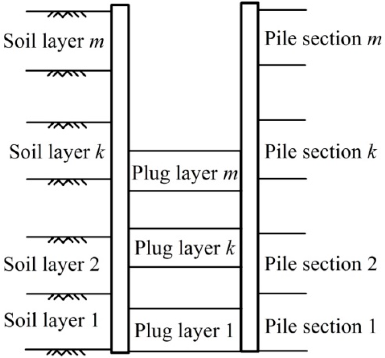
When analyzing layered soils, the pile draft can be split into a series of pile sections based on layers of foundation soil. From existing research, it is known that there is corresponding relation between layers of soil plug and layered soils. The thickness of each layer can be determined by how IFR (incremental filling ratio) varies when pile penetrates, and the soil plug can be split into a series of soil plug sections for computations, as shown in Figure 7. Each calculation pile section and soil plug section was analyzed following the computation steps of homogeneous soil. The stress and displacement of the head of the calculation section below were found at the bottom of the calculation section immediately above. Hence, the distribution of axial force of the full-length pile shaft, as well as its load-settlement curve, can be obtained.
4. Calculation Example
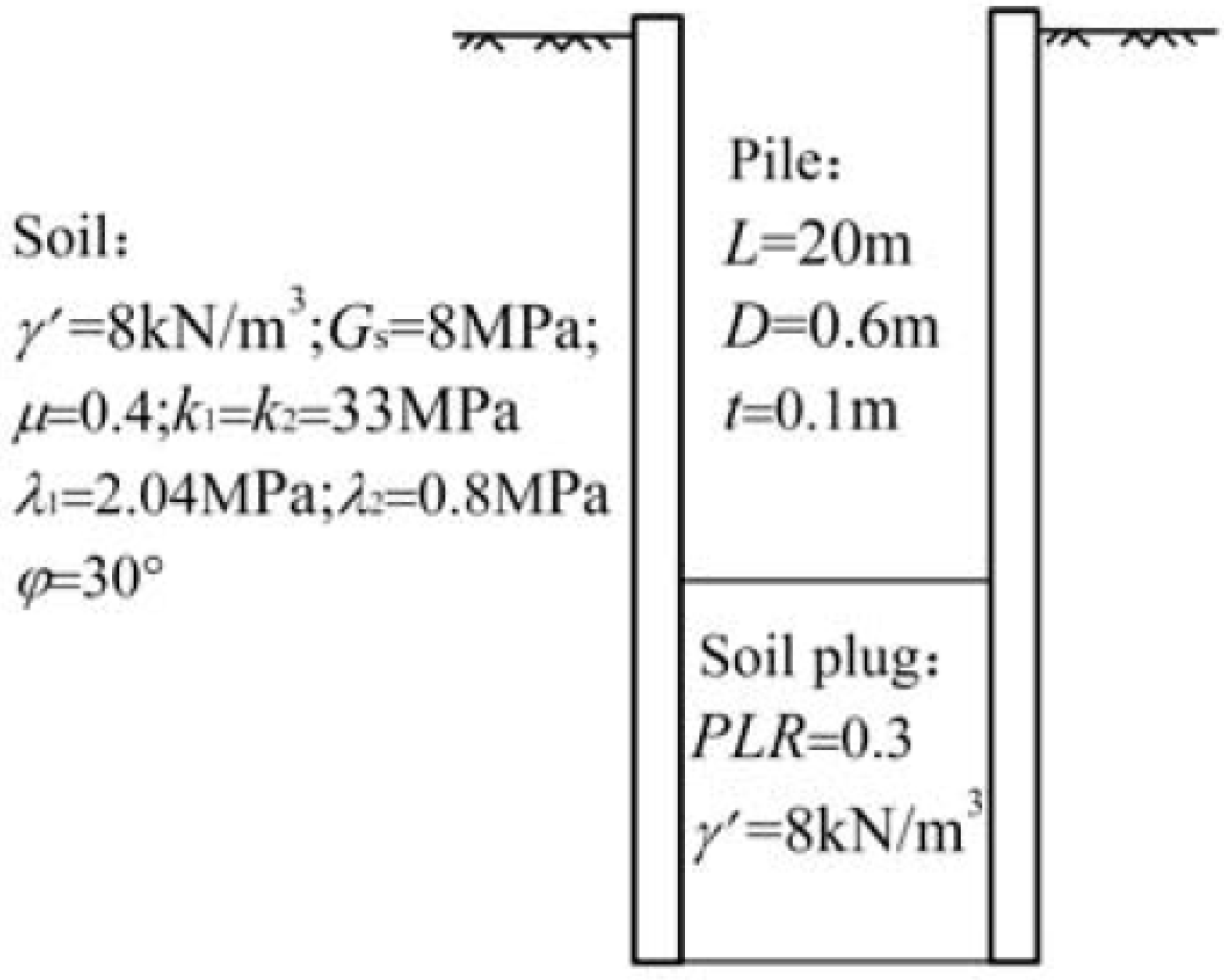
We used a calculation example to carry out a comparison analysis on the properties of load transfer of open-ended concrete pipe piles. In this example, concrete pipe piles with an outer diameter of 600 mm and a wall thickness of 110 mm were deployed, whose pile shaft elastic modulus Ep was 3.8 × 10⁴ MPa. Surrounding soil and soil at the pile end were the same as the homogeneous one; there was no bearing stratum at the pile end. We took soil plug rate (PLR) as 0.3, i.e., the length of soil plug was 6.0 m. Let each level of loading at the pile be 200 kN, and configure other parameters as in Figure 8.
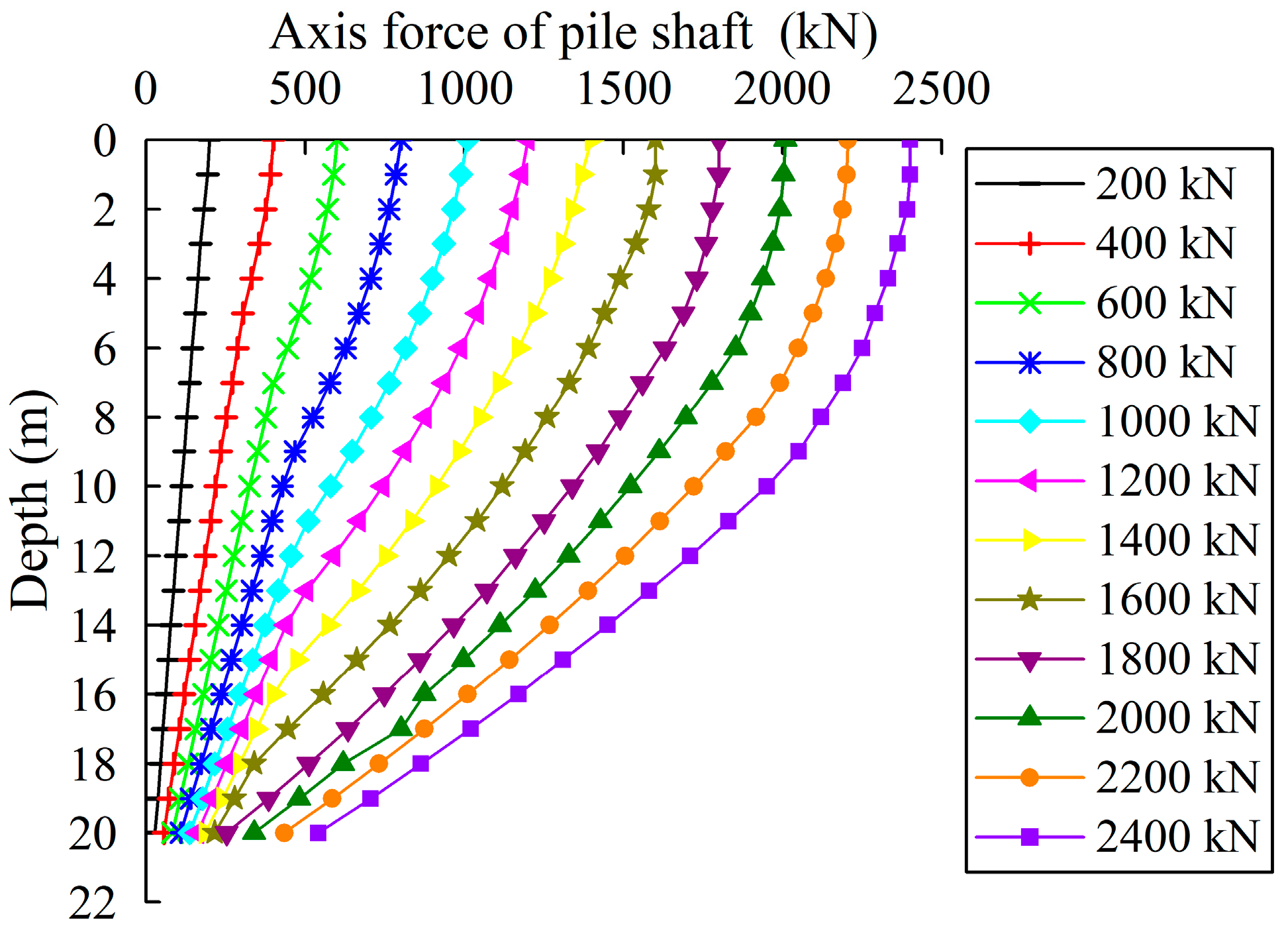
Figure 9 shows the axial force along the pile shaft under different loadings on the pile top. As we can see, at the initial stage, the bearing capacity at the pile end was not stimulated, and only properties of the pure friction pile are shown. As load increased, working load at the pile end developed gradually, and the properties of the pile were in transition from the friction pile to bearing friction pile. Moreover, at the initial stages, the distribution of axial force was roughly linear, and then transformed into a curve, whose slopes got steeper as the depth became deeper. This revealed that the friction of the lower part of the pile was greater than that of the upper part. The slope in the vicinity of the pile end changed evidently. The larger the load, the more obvious the change in slope appeared. This meant that the axial force decreased sharply, largely due to the contribution of soil plug friction.
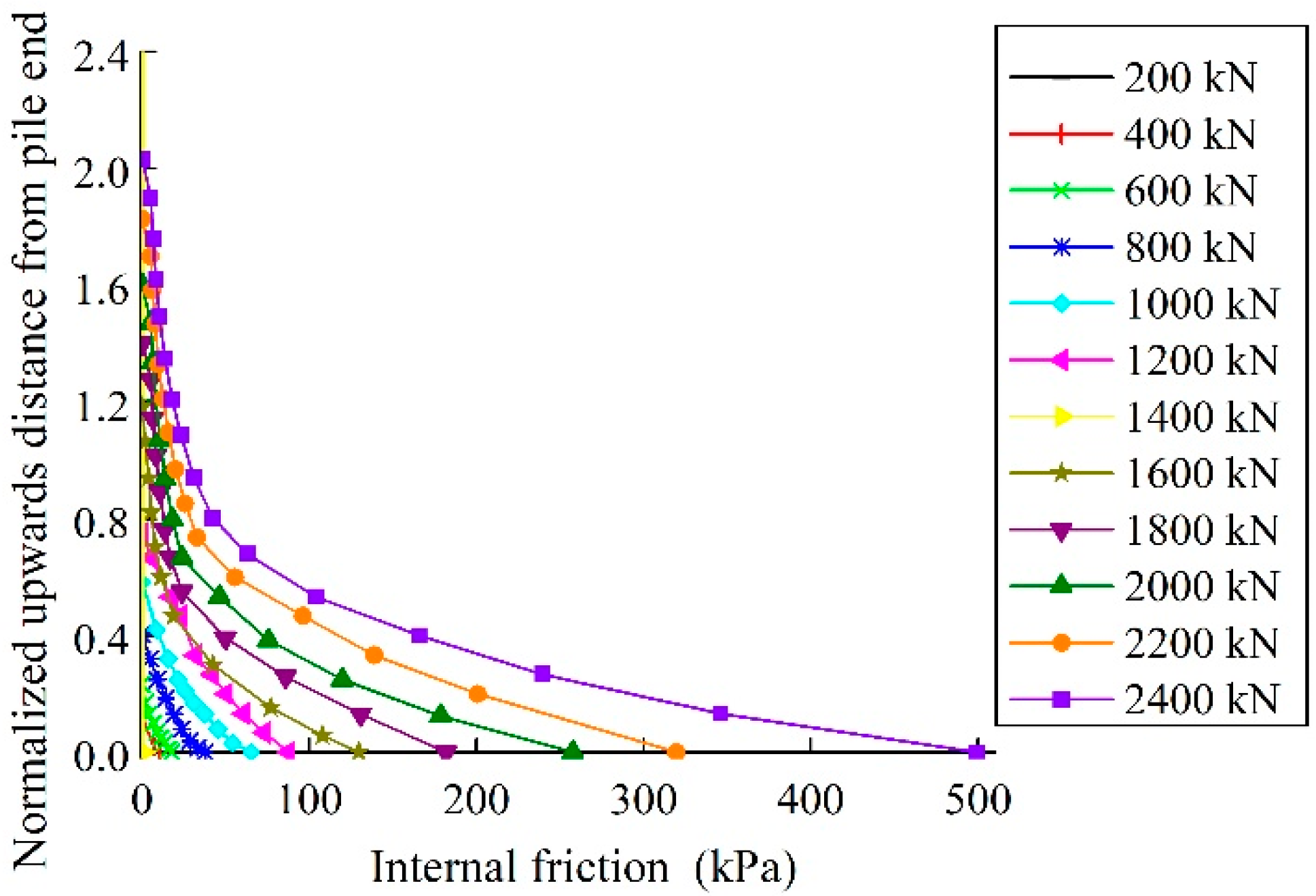
Figure 10 shows the distribution of the internal friction of pile annulus under each level of load. The distribution increased exponentially with depths. The closer it was to the pile end, the larger the friction. When the load was small, the frictional resistance provided by the soil plug was negligible. As the load increased, the frictional resistance was gradually stimulated and the effective height increased gradually as well. When the load was 2400 kN, the internal skin friction was approximately 500 kPa, which was roughly six times as large as the external skin friction in the same depth. The effective height of the soil plug was 2.03Di, which meant that the soil plug stress mainly lay close to the pile end. When the load was at its limit bearing capacity of 2150 kN, the internal skin friction at the pile end was 283 kN, which was 3.4 times as large as the external skin friction, and the effective height of the soil plug was 1.78 Di. The analysis above demonstrated that, when the working load reached the bearing capacity limit, the part of the soil plug whose friction had been developed was only within the range of two inner radiuses above the pile end. The bearing capacity of the soil plug was far from well-developed, and the soil plug end resistance depended on the development of the lower part of the soil plug, which is inconsistent with the research result of Kishida and Isemoto [31].
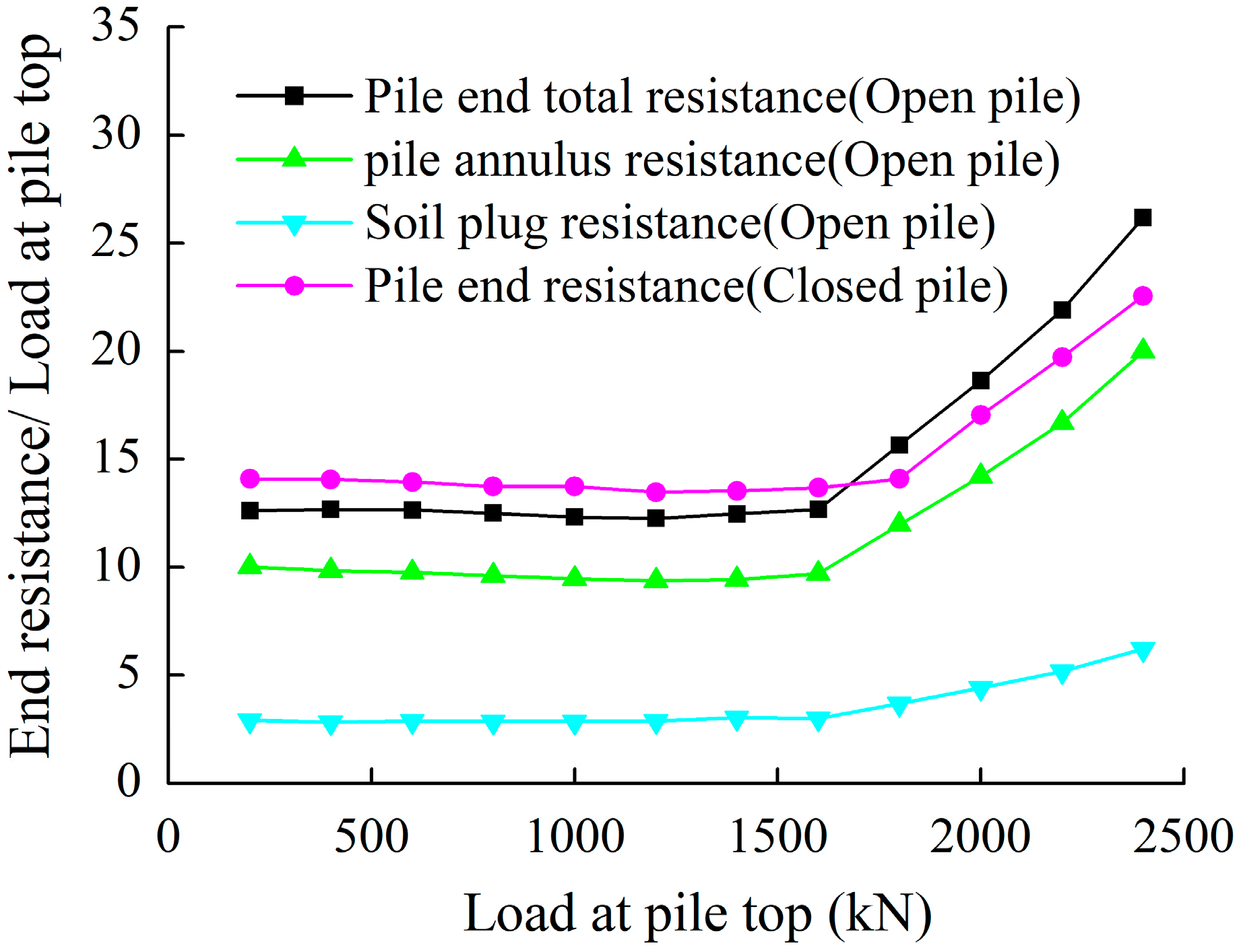
Figure 11 shows how the ratio of end resistance to the load at the pile top of two kinds of pipe piles changed with increasing load. As we can see, end resistance remained steady when the load was less than 1700 kN, and the proportion of end resistance increased gradually when the load was greater than 1700 kN. When the load reached 2400 kN, the load at the open-ended pipe pile top shared by the pile annulus and soil plug accounted for 20.1% and 6.1%, respectively. In comparison, the ratio of end-resistance to the load for the closed-ended pipe pile was 22.6%, slightly less than that of the open-ended one. This was because the squeezing effect of the closed-ended pipe pile was more significant, so that the external skin friction was much greater than that of the open-ended pipe pile, which caused only part of the soil to be squeezed. Consequently, the proportion of the external skin friction of the closed-ended pile was larger.
Figure 12 shows the curves of load-displacement at the pile top of the open-ended and closed-ended piles under the same conditions. The two curves were almost overlapping at the initial loading stage, and when load exceeded 1700 kN, the two curves started to diverge. At the later stage of loading, the settlement of the closed-ended pipe pile was smaller than that of the open-ended one, and the larger the loading, the more apparent the difference. The load values of the closed-ended and open-ended pipe piles at the displacement level of 40 mm were 2331 kN and 2150 kN, respectively, with the former being 8% greater than the latter.
5. Discrete Element Method Model
The discrete element method (DEM) has been developed and has recently been used in geotechnical engineering. The DEM is based on the explicit numerical scheme in which the interaction of particles is modelled contact-by-contact and the relative motion of the particles is modelled particle-by-particle. Therefore, the DEM makes it possible to simulate granular materials at both the micro and macro scales, and the software PFC developed by the ITASCA consulting group was applied in this study. A model open-ended pipe pile was jacked into the homogeneous sandy soil samples generated using Grid-Method [34]. An increased gravity field of 100 g was conducted in this simulation, mimicking the centrifuge testing conditions, resulting in a prototype pile with a diameter of 4.5 m and penetration length of 50 m. Each pile wall was made of two columns of overlapped particles with a radius of 1.125 mm, so as to measure the external and inner friction separately. Table 1 shows the discrete element method model input parameters. The view of system just after installation is plotted in Figure 13, and the final length of the soil plugs was 0.24 m (PLR = 0.48). The sand particles were made of disks with a maximum diameter of 7.05 mm, a minimum diameter of 4.5 mm, an average grain diameter d50 = 5.85 mm and uniformity coefficient cu = d60/d10 = 1.26. The ratio of dpile/d50 was around 8 in this model, which is close to the values suggested by Vallejo and Lobo-Guerrero [35], ensuring the efficiency and accuracy of this numerical modelling.
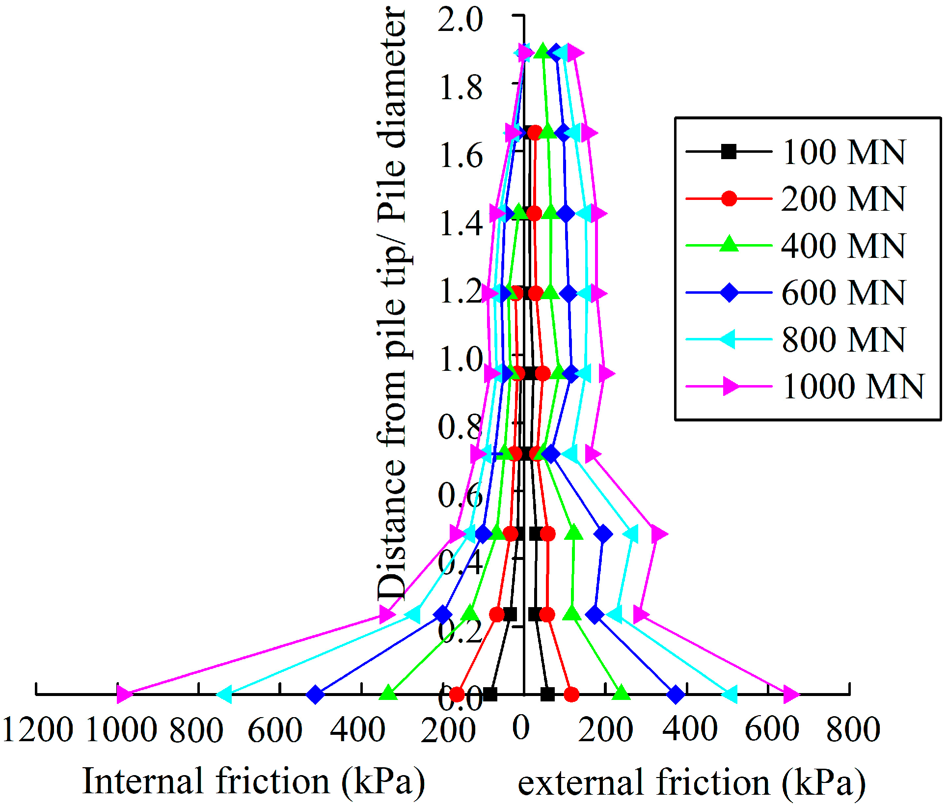
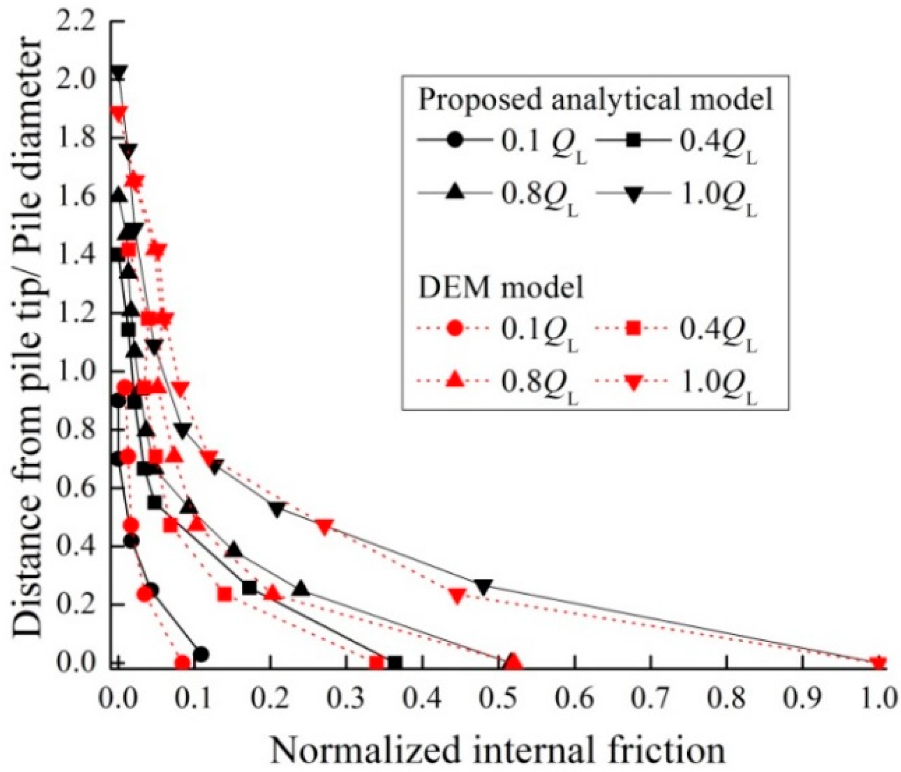
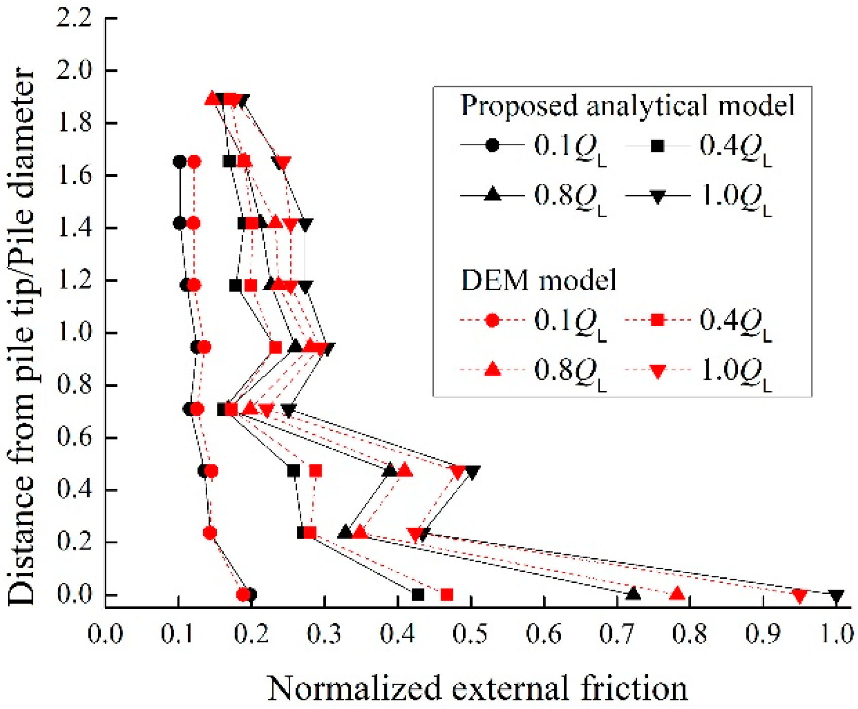
After installation of the pile, the increasing vertical static loads were applied on the pile top until they reached the limited load (i.e., the pile top settlement reached to 10% of the pile outer diameter De). It was noted that the residual stresses induced by the installation were ignored in this simulation. In order to compare the external and internal friction more clearly, only the section of 2.0 Di above the pile tip were considered, as shown in Figure 14. It was clear that both the internal and external skin frictions were gradually stimulated with increasing loads. The maximum internal skin friction at the pile end was 981 kPa, which was 50% larger than the maximum external skin friction. This ratio was close to the measurements in the piles with lower plugging degree [8,10], but was much lower than that in the above calculation example (Section 3), probably due to its higher plugging degree. Meanwhile, the internal skin friction decayed sharply with the distance from the pile tip, decreasing to less than the corresponding external skin friction above 0.4 Di. The effective height of the soil plug was 1.89 Di at the limited load, which was closed to the value of 1.78 Di obtained from the calculated example (Figure 10) and the observations from the model test [36]. The internal frictions and external frictions in this DEM model were normalized by the maximum internal friction at the pile end under limited load QL, with a normalized distance from the pile end, which are plotted in Figure 15, Figure 16, Figure 17 and Figure 18. It was clear that these distributions were close to the results from the analytical model.
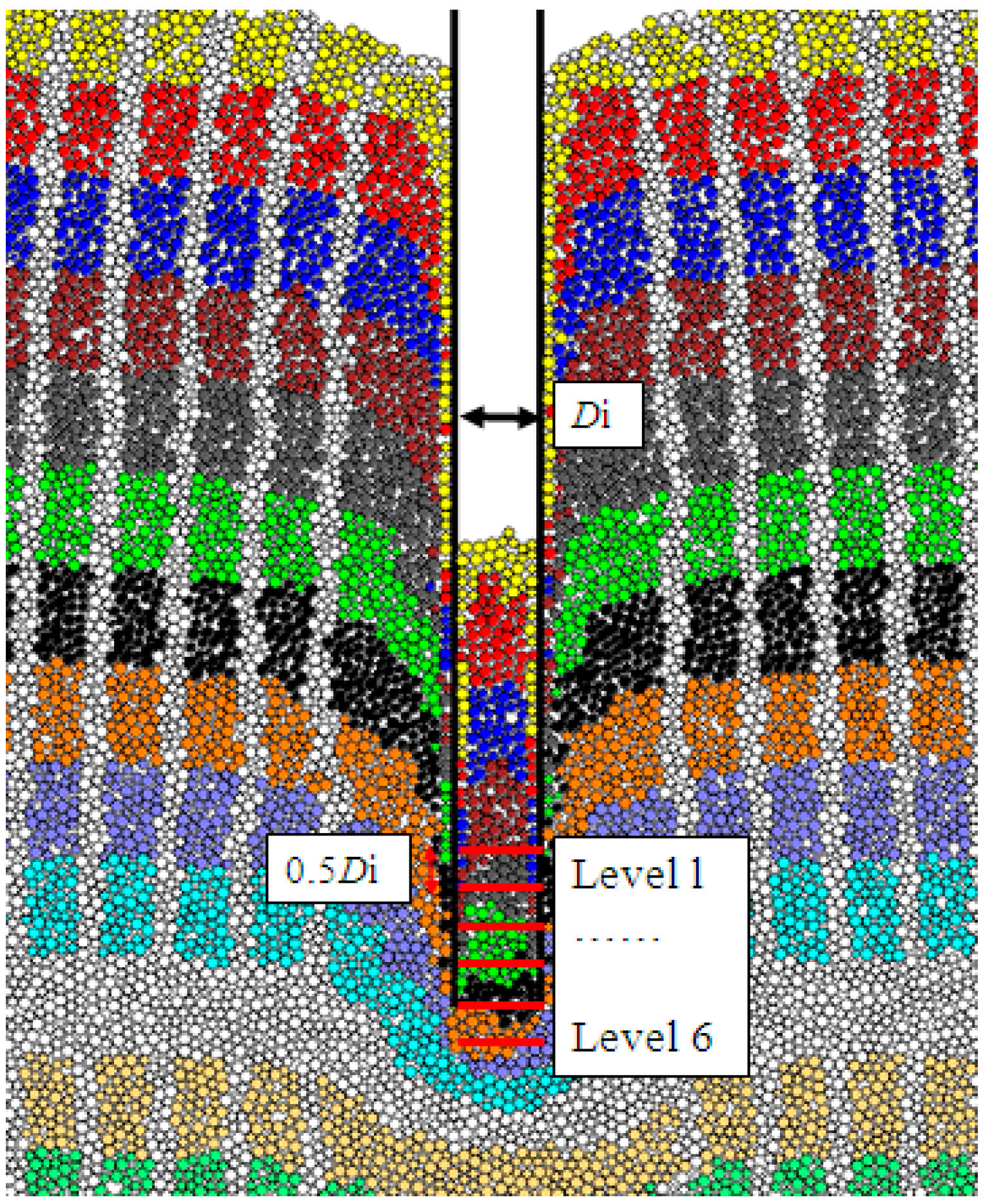
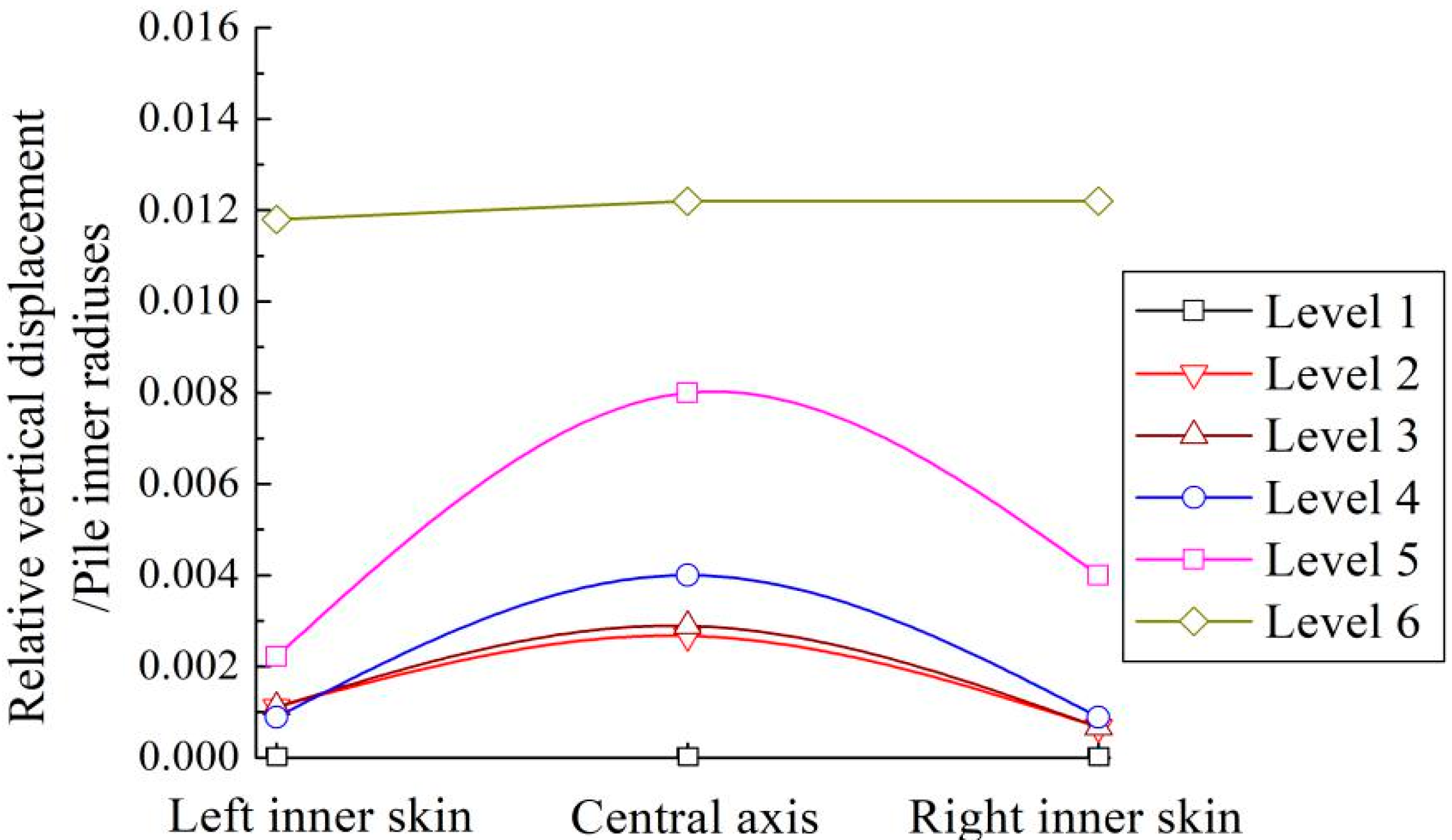
The relative vertical displacements of sand particles from the pile tip at the limited load at six levels (at 0.5 Di intervals) inside the pile at the limited load are plotted in Figure 19. It was clear that the particles at level 2–6 moved upwards relative to the pile tip, partially at and beneath the pile tip level. This indicated that the soils beneath the pile tip still further intruded into the pipe with the pile tip settlement. Even so, as the particles at levels 1 remained relatively static, the soil plug length kept constant during the whole loading process, indicating that the soil plug was compacted. This phenomenon further confirmed that the effective height of the soil plug was the portion where the soil particles moved relative to pile wall. In addition, the particles around the central axis experienced larger displacements than the adjacent pile inner skin, thus implying an “initiative arch” formed under the restriction of internal skin friction during vertical loading.
6. Concluding Comments
(1) The development mechanisms of internal and external skin frictions of open-ended pipe piles are different. While the inner soil plug was compressed during loading, the surrounding soil experienced mainly shearing deformation, and thus the external skin fiction was developed before the inside one. End resistance of the open-ended pile was shared by the pile annulus and soil plug.
(2) A kind of pile-in-pile load transfer model was established. In this model, a trilinear model was introduced to describe the load transfer at the pile-soil interface. A rigid plastic model was introduced to describe the load transfer at the pile-plug interface, and an equilibrium equation was proposed for the soil plug based on the hypothesis of a trilinear model for lateral pressure coefficient of a soil plug. A load transfer double broken line model was introduced to describe the load transfer at the pile end, done so by dividing the pile end resistance into two parts shared by the soil plug and pile annulus, respectively.
(3) The calculation example showed that the end resistance of the open-ended pile was shared mainly by pile annulus, with the proportion increasing with increasing load at the pile top. Soil plug friction was accumulated within the range of two inner radiuses above the pile end, and soil plug friction at the pile end was 3.4 times as large as the external skin friction. The bearing capacity of open-ended piles was smaller than that of closed-ended ones under the same conditions.
(4) The discrete element method model, mimicking the centrifuge testing conditions, revealed a similar load transfer process to the calculation example. Soil plug friction was generally mobilized with increasing loads, and extended upward to 1.89 inner radiuses (effective height) at a limited load. The soils beneath the pile tip intruded into pile pipe during the loading process, compacting the soil plug and thus causing the internal skin friction at the pile end to be 50% higher than the corresponding external skin friction.
Author Contributions
Conceptualization, J.L. and Z.G.; methodology, J.L.; validation, J.L., B.H. and Z.G.; formal analysis, Z.G.; investigation, B.H.; resources, J.L.; data curation, J.L.; writing-original draft preparation, J.L.; writing-review and editing, Z.G.; visualization, Z.G.; supervision, J.L.; funding acquisition, J.L.
Funding
This research was funded by National Natural Science Foundation of China (41772318, 51779220), Qingdao Fundamental Research Project (16-5-1-34-jch), Shandong Key Research and Development Plan (2017GSF20107), Open Fund of State key Laboratory of Coastal and Offshore Engineering (LP1712) and Ministry of Housing and Urban-Rural Development of China (2014-K3-026).
Conflicts of Interest
The authors declare no conflicts of interest.
References
- Randolph, M.F.; Cassidy, M.; Gourvenec, S.M. Challenges of offshore geotechnical engineering. In Proceedings of the 16th International Conference on Soil Mechanics and Geotechnical Engineering, Osaka, Japan, 12–16 September 2005; Plenary Session D; Millpress Science Publishers: Rotterdam, The Nertherlands, 2005. [Google Scholar]
- Randolph, M.F.; Gaudin, C.; Gourvenec, S.M.; White, D.J.; Boylan, N.; Cassidy, M.J. Recent advances in offshore geotechnics for deep water oil and gas developments. Ocean Eng. 2011, 38, 818–834. [Google Scholar] [CrossRef]
- Guo, Z.; Jeng, D.S.; Zhao, H.Y.; Guo, W.; Wang, L.Z. Effect of seepage flow on sediment incipient motion around a free spanning pipeline. Coast. Eng. 2019, 143, 50–62. [Google Scholar] [CrossRef]
- Li, K.; Guo, Z.; Wang, L.Z.; Jiang, H.Y. Effect of seepage flow on shields number around a fixed and sagging pipeline. Ocean Eng. 2019, 172, 487–500. [Google Scholar] [CrossRef]
- Liu, J.W.; Duan, N.; Cui, L.; Zhu, N. DEM investigation of installation responses of jacked open-ended piles. Acta Geotech. 2019. [Google Scholar] [CrossRef]
- Randolph, M.F.; Leong, E.C.; Houlsby, G.T. One dimensional analysis of soil plugs in pipe piles. Geotechnique 1991, 41, 587–598. [Google Scholar] [CrossRef]
- Yu, F.; Yang, J. Base Capacity of Open-Ended Steel Pipe Piles in Sand. J. Geotech. Geoenviron. Eng. 2012, 138, 1116–1128. [Google Scholar] [CrossRef] [Green Version]
- Ko, J.; Jeong, S. Plugging effect of open-ended piles in sandy soil. Can. Geotech. J. 2015, 52, 535–547. [Google Scholar] [CrossRef]
- Byrne, B.W. Drive pipe piles in dense sand. In Australian Geomechanics; Paper No.9501; Geonechanics Group: Perth, Australia, 1995; pp. 72–80. [Google Scholar]
- Paik, K.; Salgado, R.; Lee, J.; Kim, B. Behavior of open and closed-ended piles driven into sands. J. Geotech. Geoenviron. Eng. 2003, 129, 296–306. [Google Scholar] [CrossRef]
- Jardine, R.J.; Chow, F.C.; Overy, R.; Standing, J. ICP Design Methods for Driven Piles in Sands and Clays; Thomas Telford: London, UK, 2005. [Google Scholar]
- Gavin, K.; Lehane, B. Base load-displacement response of piles in sand. Can. Geotech. J. 2007, 44, 1053–1063. [Google Scholar] [CrossRef]
- Liu, J.W.; Guo, Z.; Zhu, N.; Zhao, H.; Garg, A.; Xu, L.F.; Liu, T.; Fu, C.C. Dynamic response of offshore open-ended pile under lateral cyclic loadings. J. Mar. Sci. Eng. 2019, 7, 128. [Google Scholar] [CrossRef]
- Randolph, M.F. Science and empiricism in pile foundation design. Géotechnique 2003, 53, 847–875. [Google Scholar] [CrossRef]
- Murff, J.D.; Raines, R.D.; Randolph, M.F. Soil plug behaviour of piles in sand. In Proceedings of the 22nd Offshore Technology Conference, OTC 6421, Houston, TX, USA, 7–10 May 1990; pp. 25–32. [Google Scholar]
- Paikowsky, S.G.; Whitman, R.V.; Baligh, M.M. A new look at the phenomenon of offshore pile plugging. Mar. Geotechnol. 1990, 8, 213–230. [Google Scholar] [CrossRef]
- Randolph, M.F.; Wroth, C.P. Analysis of deformation of vertically loaded piles. J. Geotech. Eng. Div. 1978, 104, 1465–1488. [Google Scholar]
- Randolph, M.F. RATZ Program Manual: Load Transfer Analysis of Axially Loaded Piles; Dept. of Civil and Resource Engineering, University of Western Australia: Perth, Australia, 2003. [Google Scholar]
- O’Neill, M.; Raines, R. Load Transfer for Pipe Piles in Highly Pressured Dense Sand. J. Geotech. Eng. 1991, 117, 1208–1226. [Google Scholar] [CrossRef]
- Lehane, B.; Randolph, M. Evaluation of a Minimum Base Resistance for Driven Pipe Piles in Siliceous Sand. J. Geotech. Geoenviron. Eng. 2002, 128, 198–205. [Google Scholar] [CrossRef]
- Yu, F.; Yang, J. Improved evaluation of interface friction on steel pipe pile in sand. J. Perform. Constr. Facil. 2012, 26, 170–179. [Google Scholar] [CrossRef]
- White, D.J.; Sidhu, H.K.; Finlay, T.C.R.; Bolton, M.D.; Nagayama, T. Press-in piling: The influence of plugging on driveability. In Proceedings of the 8th International Conference of the Deep Foundations Institute, New York, NY, USA, 5–7 October 2000; pp. 299–310. [Google Scholar]
- Lehane, B.M.; Gavin, K. Base resistance of jacked pipe piles in sand. J. Geotech. Geoenviron. Eng. 2001, 127, 473–480. [Google Scholar] [CrossRef]
- Jeong, S.; Ko, J.; Won, J.; Lee, K. Bearing capacity analysis of open-ended piles considering the degree of soil plugging. Soils Found. 2015, 55, 1001–1014. [Google Scholar] [CrossRef] [Green Version]
- Zhang, Z.M. Pile Foundation Engineering; China Architecture & Building Press: Beijing, China, 2007. (In Chinese) [Google Scholar]
- Liu, J.W. Experimental and Theoretical Studies on the Construction Effects for Jacked Open-Ended Concrete Pipe Piles. Ph.D. Thesis, Zhejiang University, Hangzhou, China, 2012. (In Chinese). [Google Scholar]
- Paik, K.; Salgado, R. Determination of Bearing Capacity of Open-Ended Piles in Sand. J. Geotech. Geoenviron. Eng. 2003, 129, 46–57. [Google Scholar] [CrossRef]
- Yu, F.; Zhang, Z.M. A design framework for evaluating the vertical bearing capacity of open-ended concrete pipe pile from empirical correlations. China Civ. Eng. J. 2011, 44, 100–110. (In Chinese) [Google Scholar]
- Randolph, M.F. Modelling of the soil plug response during pile driving. In Proceedings of the 9th SE Asian Geotechnical Conference, Bangkok, Thailand, 7–11 December 1987; pp. 6.1–6.14. [Google Scholar]
- Liu, J.W.; Zhang, Z.Z.; Yu, F. Case history of installing instrumented jacked open-ended piles. J. Geotech. Geoenviron. Eng. 2012, 12, 810–820. [Google Scholar] [CrossRef]
- Kishida, H.; Isemoto, N. Behaviour of sand plugs in open-end steel pipe piles. In Proceedings of the 9th International Conference Soil Mechanics, Tokyo, Japan, 10–15 July 1977; pp. 601–604. [Google Scholar]
- Paik, K.H.; Lee, S.R. Behavior of soil plugs in open-ended model piles driven into sands. Mar. Georesour. Geotechnol. 1993, 11, 353–373. [Google Scholar] [CrossRef]
- De Nicola, A.; Randolph, M.F. The plugging behavior of driven and jacked piles in sand. Geotechnique 1997, 47, 841–856. [Google Scholar] [CrossRef]
- Duan, N.; Cheng, Y.P. Discrete Element Method Centrifuge Model of Monopile under Cyclic Lateral Loads. Int. J. Environ. Chem. Ecol. Geol. Geophys. Eng. 2016, 10, 200–205. [Google Scholar]
- Vallejo, L.; Lobo-Guerrero, S. DEM analysis of crushing around driven piles in granular materials. Géotechnique 2005, 55, 617–623. [Google Scholar]
- Kumara, J.J.; Kikuchi, Y.; Kurashina, T. Effective Length of the Soil Plug of Inner-Sleeved Open-Ended Piles in Sand. J. GeoEng. 2015, 10, 75–82. [Google Scholar]
Figure 1.
Load transfer diagram for open-ended pipe pile. ((a) Open-ended pile defined as “pile in pile” system, (b) pile annulus defined as “outer pile”, (c) soil plug defined as “inner pile”.).
Figure 1.
Load transfer diagram for open-ended pipe pile. ((a) Open-ended pile defined as “pile in pile” system, (b) pile annulus defined as “outer pile”, (c) soil plug defined as “inner pile”.).

Figure 2.
Load transfer trilinear model of pile-soil interface.

Figure 3.
Trilinear model for the distribution of lateral pressure coefficient for the soil plug.

Figure 4.
Load transfer model for pile tip.

Figure 5.
Calculation model for surrounding soil. ((i) elastic stage, (ii) plastic stage, (iii) sliding stage).
Figure 5.
Calculation model for surrounding soil. ((i) elastic stage, (ii) plastic stage, (iii) sliding stage).

Figure 6.
Stress conditions within the soil plug ((a) equilibrium of soil plug, (b) equilibrium of soil plug unit, (c) side pressure coefficient model of soil plug).
Figure 6.
Stress conditions within the soil plug ((a) equilibrium of soil plug, (b) equilibrium of soil plug unit, (c) side pressure coefficient model of soil plug).

Figure 7.
Computation diagram of the pipe pile in layered soils.

Figure 8.
Sketch map of computing case.

Figure 9.
Distribution of axial force for open-ended pipe.

Figure 10.
Distribution of internal skin friction under loading.

Figure 11.
Change in the ratio of end resistance to load under loading.

Figure 12.
Curve of load-displacement at the pile top.

Figure 13.
View of pile-soil system just after installation.

Figure 14.
Comparison of internal and external skin friction under loading.

Figure 15.
The internal friction from the analytical method and DEM model.

Figure 16.
The external friction from the analytical method and DEM model.

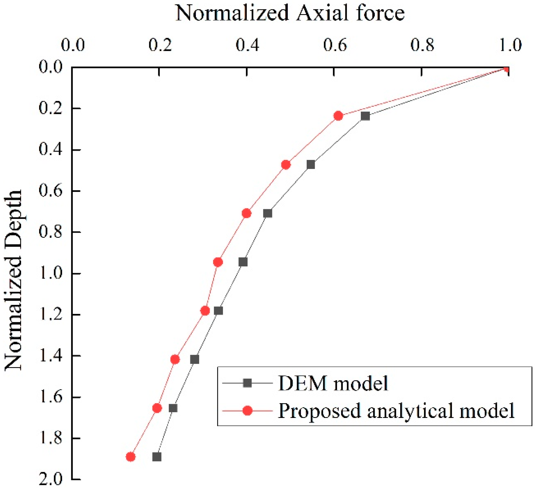
Figure 17.
The axial force-depth from the analytical method and DEM model.

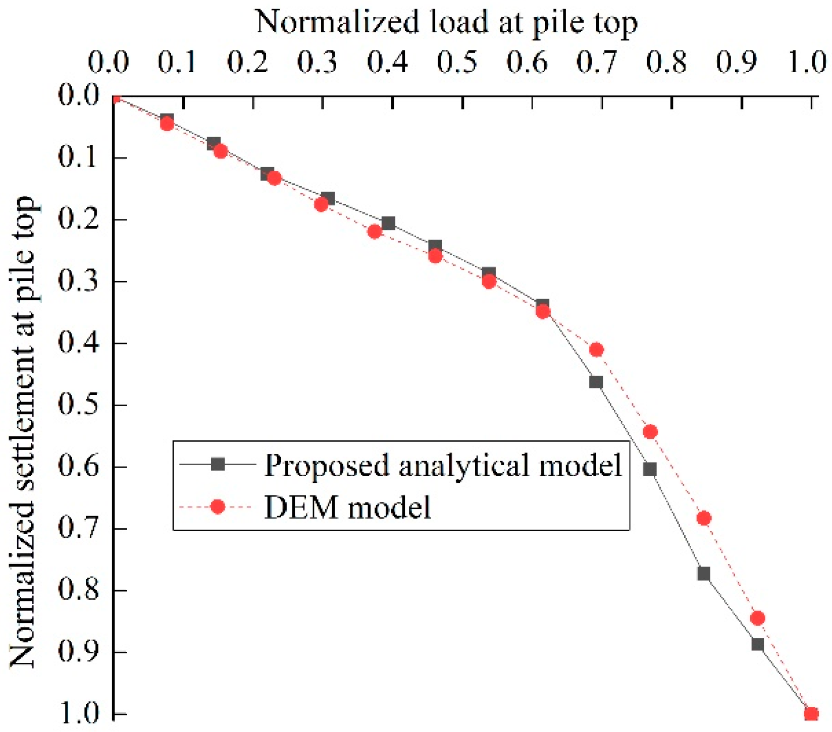
Figure 18.
The load at pile top versus the settlement from the analytical method and DEM model.

Figure 19.
Relative vertical displacements at six levels inside the pile.


Table 1.
Input parameters for discrete element method (DEM) simulations.
| Simulation Parameters | Value |
|---|---|
| Density of sand particles (kg/m3) | 2650 |
| Density of particles for pile (kg/m3) | 500 |
| Average particle size (mm) | 5.85 |
| Pile outer diameters (mm) | 45 |
| Pile inner diameters (mm) | 39.6 |
| Model pile length (mm) | 500 |
| Model container width (mm) | 1200 |
| Model container depth (mm) | 600 |
| Friction coefficient of the particles | 0.5 |
| Friction coefficient of pile and walls | 0.5 |
| Young’s modulus of particles (Pa) | 4 × 10⁷ |
| Contact normal stiffness of pile and particles (N/m) | 8 × 10⁷ |
| Particle stiffness ratio (ks/kn) | 0.25 |
| Contact normal stiffness of walls (N/m) | 6 × 10¹² |
| Initial average porosity | 0.25 |
| Final average porosity (final equilibrium) | 0.185 |
| Bulk unit weight (kN/m3) | 2115.3 |
© 2019 by the authors. Licensee MDPI, Basel, Switzerland. This article is an open access article distributed under the terms and conditions of the Creative Commons Attribution (CC BY) license (http://creativecommons.org/licenses/by/4.0/).
Share and Cite
MDPI and ACS Style
Liu, J.; Guo, Z.; Han, B. Load Transfer of Offshore Open-Ended Pipe Piles Considering the Effect of Soil Plugging. J. Mar. Sci. Eng. 2019, 7, 313. https://doi.org/10.3390/jmse7090313
AMA Style
Liu J, Guo Z, Han B. Load Transfer of Offshore Open-Ended Pipe Piles Considering the Effect of Soil Plugging. Journal of Marine Science and Engineering. 2019; 7(9):313. https://doi.org/10.3390/jmse7090313
Chicago/Turabian StyleLiu, Junwei, Zhen Guo, and Bo Han. 2019. "Load Transfer of Offshore Open-Ended Pipe Piles Considering the Effect of Soil Plugging" Journal of Marine Science and Engineering 7, no. 9: 313. https://doi.org/10.3390/jmse7090313
Note that from the first issue of 2016, this journal uses article numbers instead of page numbers. See further details here.