
Advances in Reconfigurable Vectorial Thrusters for Adaptive Underwater Robots
by
 , , and
Henrique Fagundes Gasparoto
1 ,
,
Olivier Chocron
2 ,
,
Mohamed Benbouzid
3,4,* and
and
Pablo Siqueira Meirelles
5
1
Lab-STICC (UMR CNRS 6285), Team ROBEX, ENSTA Bretagne, CEDEX 9, 29806 Brest, France
2
Institut de Recherche Dupuy de Lôme (UMR CNRS 6027 IRDL), ENI Brest, CEDEX 3, 29238 Brest, France
3
Institut de Recherche Dupuy de Lôme (UMR CNRS 6027 IRDL), University of Brest, 29238 Brest, France
4
Logistics Engineering College, Shanghai Maritime University, Shanghai 201306, China
5
Department of Computational Mechanics, Faculty of Mechanical Engineering, State University of Campinas (UNICAMP), Campinas, SP 13083-860, Brazil
*
Author to whom correspondence should be addressed.
J. Mar. Sci. Eng. 2021, 9(2), 170; https://doi.org/10.3390/jmse9020170
Submission received: 16 January 2021
/
Revised: 29 January 2021
/
Accepted: 30 January 2021
/
Published: 7 February 2021
(This article belongs to the Special Issue Feature Reviews in Marine Science and Engineering)
Abstract
:Manoeuvrability is one of the essential keys in the development of improved autonomous underwater vehicles for challenging missions. In the last years, more researches were dedicated to the development of new hulls shapes and thrusters to assure more manoeuvrability. The present review explores various enabling technologies used to implement the vectorial thrusters (VT), based on water-jet or propellers. The proposals are analysed in terms of added degrees of freedom, mechanisms, number of necessary actuators, water-tightness, electromagnetomechanical complexity, feasibility, etc. The usage of magnetic coupling thrusters (conventional or reconfigurable) is analysed in details since they can assure the development of competitive full waterproof reconfigurable thrusters, which is a frictionless, flexible, safe, and low-maintenance solution. The current limitations (as for instance the use of non conductive hull) are discussed and ideas are proposed for the improvement of this new generation of underwater thrusters, as extending the magnetic coupling usage to obtain a fully contactless vector thrust transmission.
1. Introduction
Technology is a vital tool in the activity of human exploration. Whether on our planet, in our solar system or even in the exploration of other stars, humanity has dedicated, dedicates and will dedicate great efforts in the development of technologies that allow us to go beyond the known limits. Looking only at our planet, it is always possible to see scientific initiatives with the purpose of exploring areas and systems not yet wholly dominated, as one can see in the excavations carried out in the Antarctic continent, in diving into deep waters to expand the knowledge of oceanic ecosystems, as well as islands, denser jungles and other less accessible systems.
In environments not favourable to human presence, it is recurrent to use autonomous, supervised, or remotely controlled machines, i.e., robots. In the exploration of the planet Mars, the use of robotic vehicles counts already as successful examples from the Sojourner to Curiosity [1]. Recently, a group that included the renowned physicist Stephen Hawking announced the project Breakthrough Starshot, which intends to send a large number of mini robot ships to the nearby solar system, i.e., Alpha Centauri [2].
In our globe, biologists have expanded the use of drones for research in dense forests, and institutions are adopting such vehicles for their monitoring with the intention of preserving these areas. Moreover, rivers and oceans are also explored through remotely operated underwater vehicles (ROV) or more recently by autonomous underwater vehicles (AUV).
Beyond the Earth limits, humanity is feeding other ambitions in the NASA’s project SUBSEA [3], which aims to find extraterrestrial life through the exploration of hydrothermal systems of underwater volcanoes, in a hidden ocean beneath the icy crust of Saturn’s moons Enceladus and Europa.
Nevertheless, the use of underwater vehicles is not only restricted to scientific research interests. Since the last decades of the XXth century, autonomous robots are used in other tasks where the activity of divers is costly, dangerous or even impossible. There is an important interest in these robots for the maintenance of marine renewable energy (MRE) systems (underwater devices such as offshore wind turbines, tidal power plants, or hydroelectric dam underwater structures). Moreover, there are also interests in military applications (mine warfare, sensitive areas protection, identification of magnetic and electric boats signatures), port activities (monitoring of installations, inspection and maintenance of ships hull), or maritime safety (pollution control, search for wrecks, emergency response to submarine disasters), and for offshore industry activity (pipelines or telecommunication cables).
For all these missions, underwater interventions on complex geological or fabricated architectures—which are usually obstacle infested and hostile environments—require fully autonomous underwater vehicles (AUVs) with advanced key technologies [4], as enhanced manoeuvring capabilities [5], controlled with the most intelligent algorithms. These more stringent demands imply the need to expand the capabilities of AUVs such as speed, power, control, perception, autonomy, and depth [6]. However, the propulsion and control systems for this robot kind have not improved as quickly as their needs, which restricts their performance and thus their autonomy. According to [7], it is necessary to give long-range and manoeuvring capabilities to AUVs to advance to a new generation of underwater robots (UR) able to perform a more extensive set of operations. What refers to two design aspects of these vehicles: hull shape (e.g., torpedoes have a streamlined shape to favour hydrodynamic penetration) and propulsion system. In [5], it is observed that investigations and developments have been conducted about underwater vehicles locomotion, but few are dedicated to the propulsion system itself. Therefore, this review presents the last advances in underwater propulsion systems, beginning by Section 2 presentation. Next, Section 3 (or simply reconfigurable thrusters, RT) are addressed. RT are the most promising branch of vectorial thrusters (VT), which allows the reorientation the thrust vectors. For full propeller-based waterproof RTs, the usage of magnetic couplings (MC) or joints is indispensable. It is presented in the Section 4. Finally, Section 5 are carried-out.
2. Propulsion Types
The propulsion systems of underwater vehicles can be divided into four categories:
It is immediate that the propulsion architecture of a vehicle determines its set of possible motion directions, as well as influences the ability to control the movement.
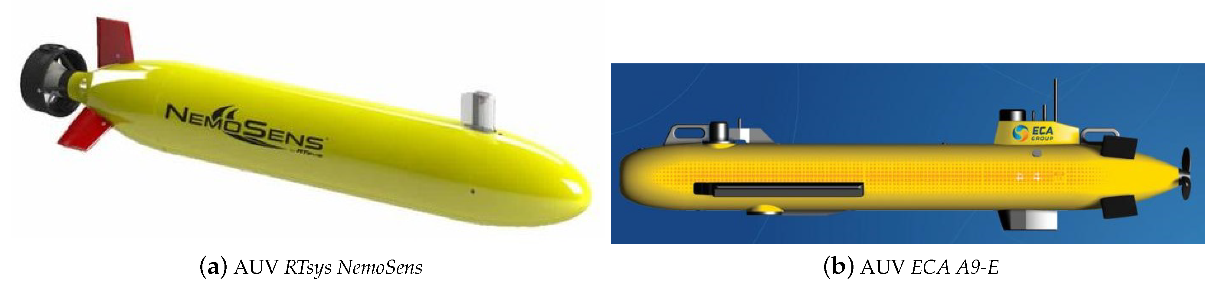
Classical rear propeller with control surface architectures, such as in large conventional submarine equipped with rudders, take an important place in AUV market since it has a great performance following straight lines due to their torpedo-shaped hull. It is possible to see many commercial examples as in the AUV RTsys COMET 300 [8], in the AUV RTsys NemoSens [9], in the AUV ECA A9-E [10] and M [11], in the AUV ECA A18-D [12], E [13], and M [14], in the AUV ECA A27-E [22] and M [15].
However, this option offers low manoeuvrability.
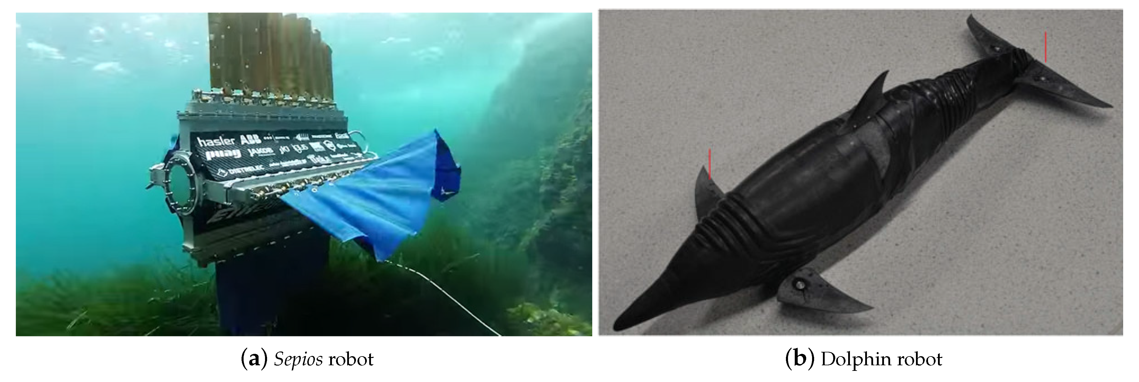
Biomimetic and bioinspired propulsions (Figure 2), i.e., mimicked or inspired, receptively, come from natural propulsion mechanisms present in marine life, such as dolphins and whales fins as in [17,18], or eel-like [19], or fishes as in [20,21]. These propulsion systems are usually made with many DOFs of actuation (e.g., Figure 2a), which are difficult to implement and control. However, it presents important advantages and has become a growing research subject [45] which studies the aspects that interfere on the manoeuvrability [46,47].
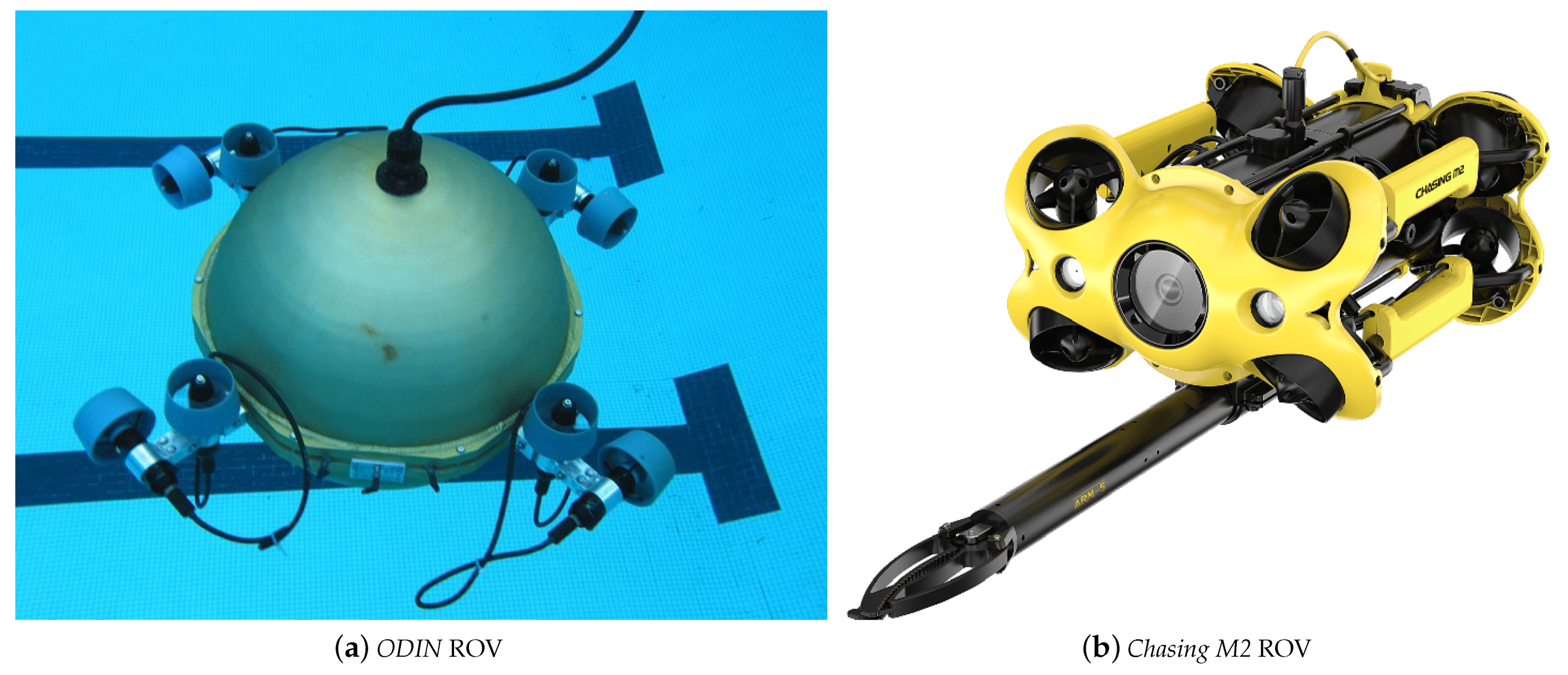
In VT propulsion systems (Figure 3 and Figure 4), it is possible to drive and steer the vehicle only using thrusters through various strategies. A single fixed thruster (FT) endows the robot with only a thrust vector (with fixed direction in Figure 6), which does not allow trajectory tracking. This issue is solved with the combination of several FTs acting in different directions and with different thrust vectors , placed differently by a position vector , as in robot ODIN [42,43] (Figure 4a), which can be considered the first underwater robot with a full holonomic propulsion [48]. Another newest possibility is to use a few or a single reconfigurable thruster (RT) [26], since they may have their thrust vectors redirected, which involves more than one degree of freedom (DOF) per thruster, and so, an integrated solution for propulsion and guidance [27].
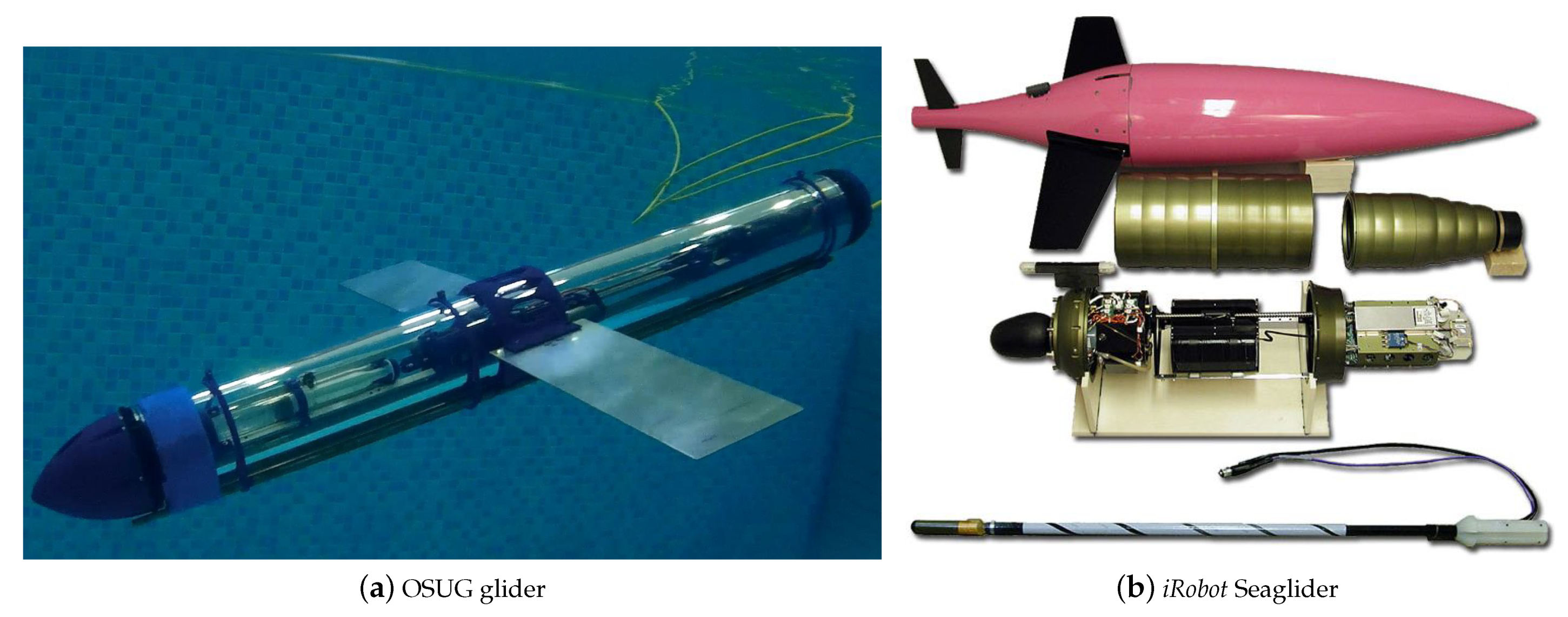
The underwater gliders (Figure 5) can be considered a separate case because they do not include an active propulsion system, but rather a buoyancy-gravity or a mass shifter controlled device. This system, coupled with fixed fins allows a dive-wise alternating movement not controlled in heading and only partially in planar speed. Some hybrid vehicles gather buoyancy-gravity actuators and propellers or rudders [38], they then belong to this fourth category.
In terms of manoeuvrability that is the heart of this paper, classical rear propeller with control surface architectures are less manoeuvrable because the control action is reactive and indirect since the vehicle cannot be steered if there is no advance. Underwater gliders are still less manoeuvrable since their rudders are not controllable. Biomimetic and bioinspired propulsions can reach great manoeuvrable architectures but usually requiring many DOFs of actuation. Vectorial thrust using fixed thrusters (FT) can be highly manoeuvrable if equipped with many thrusters, sometimes greater than 6 as in ROV ODIN [42,43] (Figure 4a). The propulsion architecture is so endowed with many thrust vectors in different directions and the control system works to define the correct intensity of each one. It results in a total force and torque propulsion vectors, respectively and , shown in Figure 6. Vectorial thrust using reconfigurable thrusters (RT) can significantly reduce the total number of thrusters. It is possible because, not only the intensity of vectors are changed but also their directions in this type of propulsion architecture. Moreover, the vector reorientation by a servomotor, for example, is usually faster than the intensity change. Moreover, the possibility of the robot reconfiguration allows the optimized choice of the reconfigured propulsion architecture according to different tasks, minimizing the trajectory tracking error and energy consumption [49].
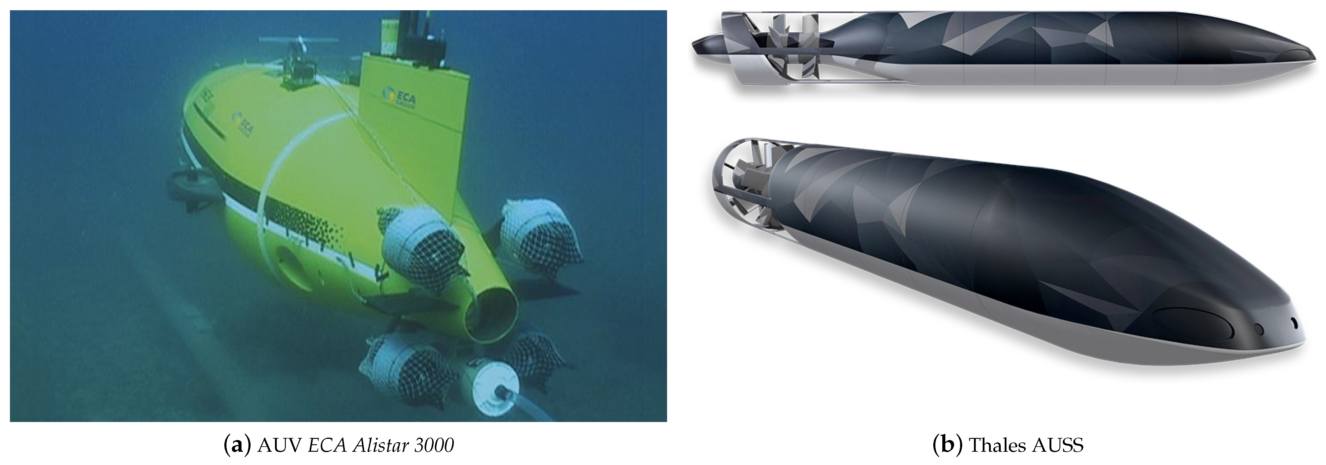
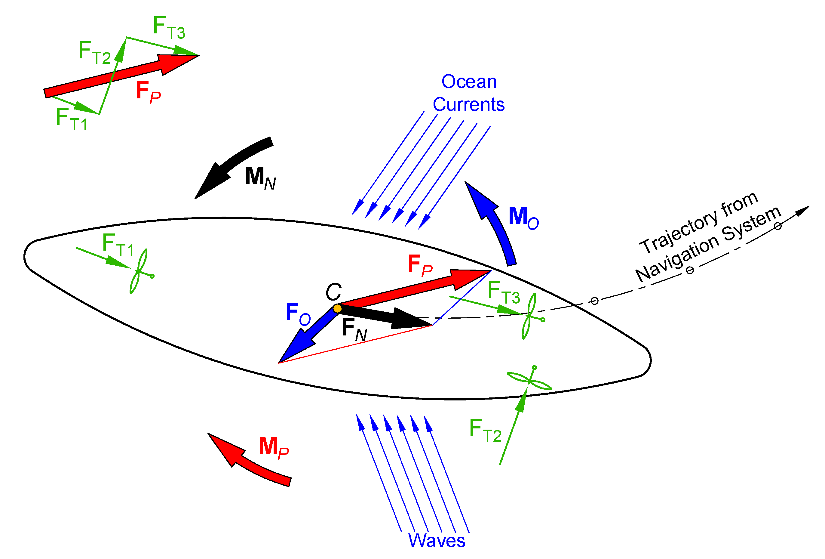
Figure 6 presents a 2D model for the vectorial thrust approach. In this figure, the vehicle thrusters are propeller-based. However, VT propulsion type includes also jet-based thrusters, which is a convergence point with bioinspired robots, as it is possible to see in the jellyfish [50]. In this context, the propulsion technique called synthetic jet is considered here in the VT group, but its dynamic based in pulsatile vortex generators is more complex [23,24]. Still, other advanced hydrodynamic techniques, as one based in double propellers in an autonomous underwater and surface system (AUSS) [25] (Figure 3b), are also considered in the VT group.
In Figure 6, the vehicle has to follow a defined trajectory keeping the desired orientation. For that, temporal needed efforts and , in the centre C, are calculated. However, the vehicle is under ocean efforts that also changes along the time, represented by and , acting in point C. Hence, to follow the given trajectory with the desired orientation, the vehicle propulsion system has to calculate and generate, continuously, the propulsion vectors defined as:
and
also calculated in C. If the vehicle is equipped with more than one vectorial thruster, and are given by
and
The penetration of VT technology in commercial AUVs is verified more by the adoption of FT-based architectures than RT ones. It is due to the intrinsic complexity in terms of mechanism making of RTs. Moreover, RT control systems are harder than FT ones that can use known PID strategies since the relation command-torsor is linear, which is not the case with RTs. FT industrial examples are found in the ROV Victor 6000 [28], the AUV ECA Alistar 3000 [22] Figure 3a, and the AUV ECA A18-TD [29]. New personal portable underwater drones for photographies usually are FT-based as in drones Chasing F1 [30], M2 [31], Dory [32], Gladius Mini [33], and the drone PowerRay [34]. A military example of an advanced RT-based prototype is the autonomous underwater and surface system (AUSS) from Thales Group [25] (Figure 3b). Many RT-based architectures are in development and they will be better discussed in Section 3.
3. Advances in Reconfigurable Vectorial Thrusters
One of the RT systems advantages over FT ones is the possibility of reducing the number of thrusters to the minimum, which reduces the total vehicle mass and volume. Another advantage is the possible reduced consumption of energy when changing directions [7] since, in most options, it is only necessary to change the orientation of the propeller or duct. However, to guarantee a greater manoeuvrability and increased controllability of AUVs, an RT must be endowed with the highest possible capability to reorient its thrust vector [51]. This means a great angle range and more DOF per thrusters.
In the last two decades and more intensively in the last one, researches have been carried out to advance in the development of different RT types. The advance in RT propulsion can be divided into two groups: propeller-based and pumped-water-jet-based RTs. Moreover, other RT characteristics can organise them in other groups. For example, between options where only the water flux has its direction reoriented by ducts or nozzles, or options where the pump or propeller with their motors have to be reoriented as well. The latter aspect is relevant for the inertia analysis, which determines needed forces, torques, and power-supply for a fast reconfiguration.
Another indispensable question is how many ideas were converted in submersible prototypes. It is a crucial point since RT thrusters with 3-DOF are sometimes equipped with a parallel mechanism that depends on 4 actuators, and most of the proposals do not address the water-tightness issue in transmitting all these movements outside the robot hull. Most of the works present different RT architectures for studying different control strategies, but the construction feasibility is not addressed. Below, some relevant RT architectures propositions are chronologically presented, and they are highlighted every time a proposal comes with a submersible prototype.
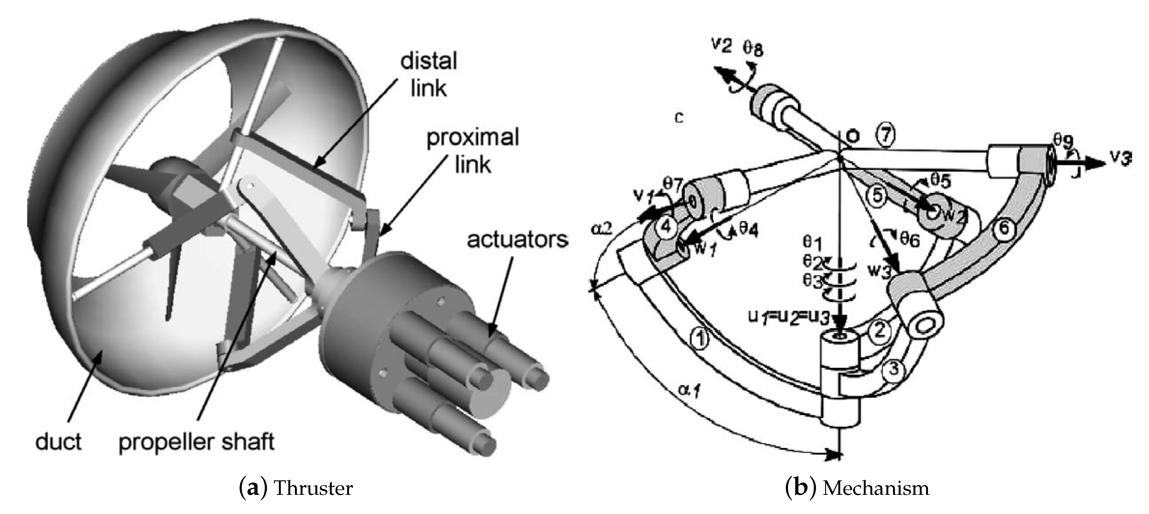
In [52] (2000), an RT in a “MicroAUV” is presented, with the water-jet reorientation reached by its tail reconfiguration. In [27] (2004, Figure 7), an RT is developed with 3-DOF of the duct and propeller reconfiguration, using a spherical parallel mechanism with 4 actuators (one for the main power transmission and the other three for the reconfiguration).
In [51] (2008), the concept of a propeller-based reconfigurable magnetic coupling thruster (RMCT) is introduced, modelled, and experienced.
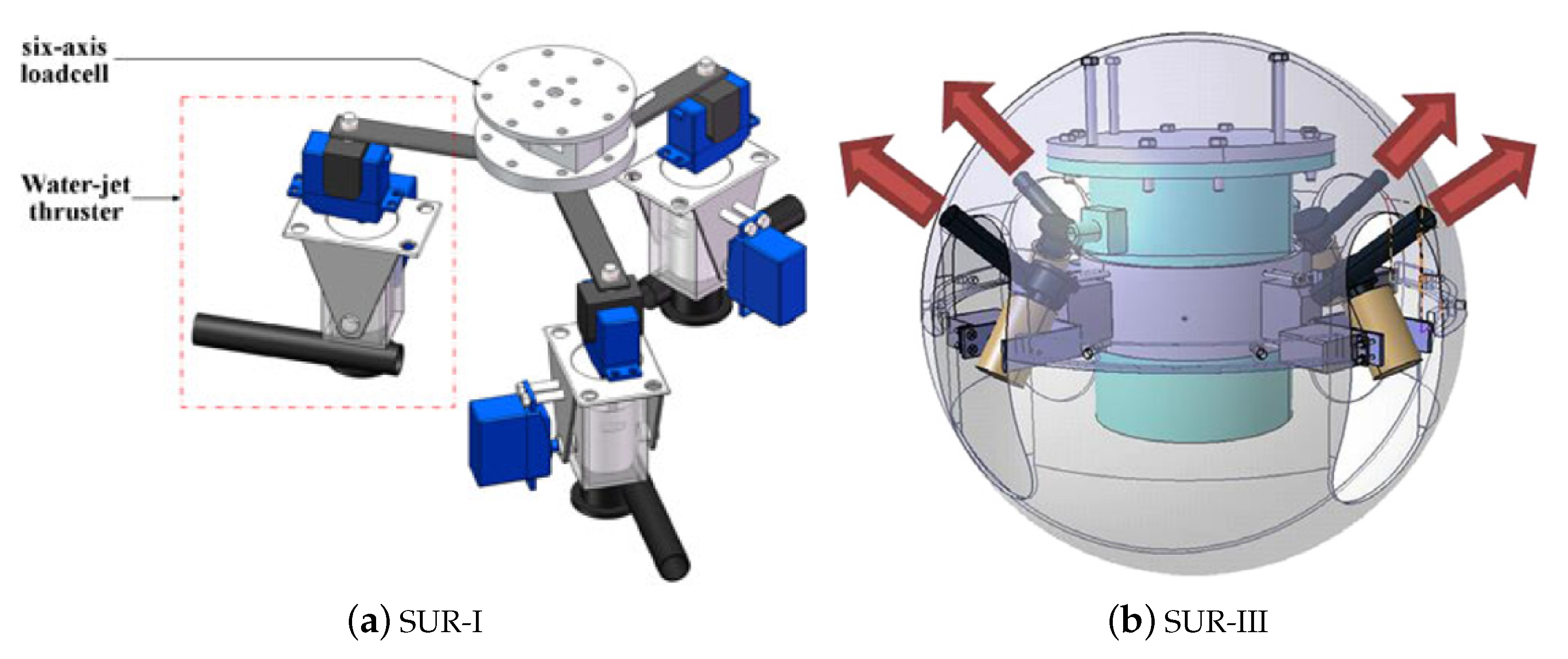
In [53] (2009), it is introduced a novel architecture with three pumped-water-jet-based RT, each one with 2-DOF controlled by two servo-motors. Here, the jet force is not a DOF associated since the water-jet pressure is constant. After one year, it is possible to see the evolution of this concept in [54] (2010), where the architecture concept with three pumped-water-jet-based RT evolved for a prototype in construction. And, finally, a real spherical underwater robot (SUR) is presented with the three pumped-water-jet-based RT in [55] (2012, see Figure 8a).
In the same year, in [57] 2012, the prototype of the MASUV-1 robot is presented (Figure 9). MASUV-1 is a small real underwater vehicle with an RT-based on nozzle orientation that redirects the propeller flow with 2-DOF (total of 3-DOF), keeping the propeller out of reach of marine life, and not requiring any shaft reorientation. It is interesting to note in MASUV-1 propulsion technology how concepts of water-jet and propeller-based RTs are combined. The range of reconfiguration of MASUV-1 is equal to for both reconfiguration angles.
In [58] (2013, see Figure 10), similarly to [53] (2009), a pumped-water-jet-based RT is presented, using three actuators to assure more 2-DOF of reconfiguration to the thrust. In the same year, two propositions were published showing the application of RTs in two different propulsion architectures (see Figure 11): the Smart-E AUV [59] and the so called Italian sea-stick [60] apud [61]. In these publications, RTs are called pivoted thrusters. The Smart-E AUV realizes a holonomic drive with only three thrusters. The Italian sea-Stick is a hybrid solution since it is also equipped with rudders.
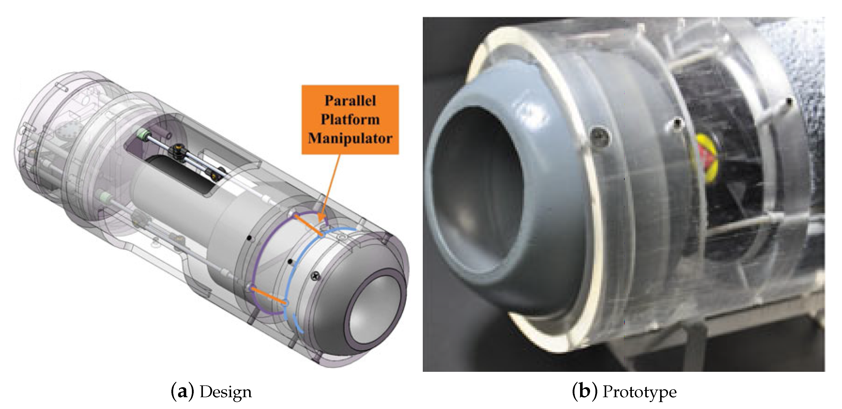
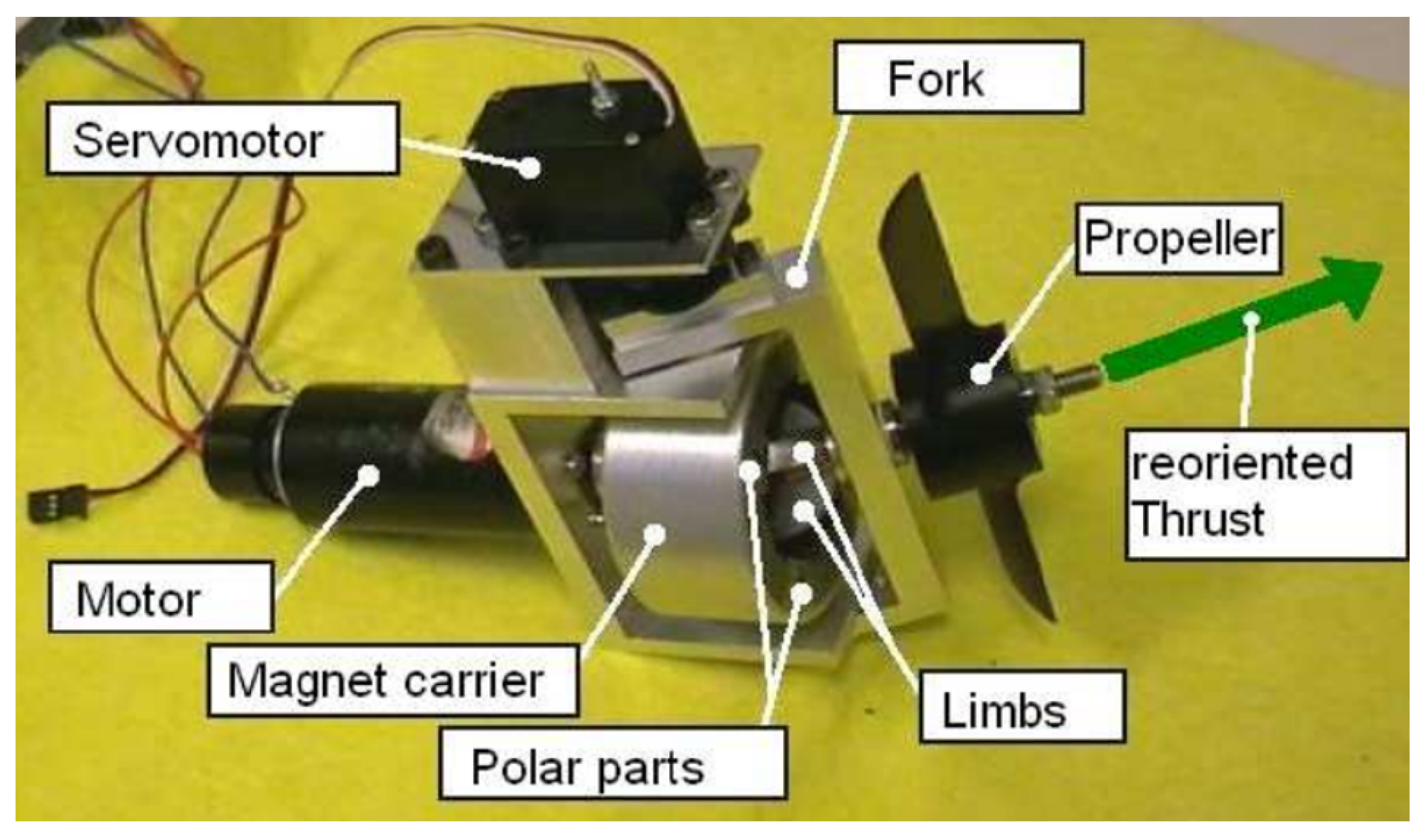
In [5] (2014, see Figure 12), the RMCT concept presented in [51] (2008) evolves for a non-submersible prototype, using a spherical reconfigurable magnetic coupling (S-RMC) or joint, with one actuator to assure 1-DOF of reconfiguration.
In [4] (2015), authors analysed the state of the art in key technologies for AUVs and indicate that the RT technologies were not yet mature and so, they propose a 3-DOF orientable motor-to-propeller transmission mechanism (see Figure 13), based on ball gear, with wide range wrist rotation. However, their review did not take into account advances in the RMCT concept, since they analysed only water-jet and mechanical transmission systems. In [62] (2017), more details are shown about the motor-to-propeller transmission mechanism, based on ball gear. The design shows a range of reconfiguration near to for both reconfiguration angles. However, in the test photos, this range seems closer to .
In [63] (2015, see Figure 14a), a tilt thrusting underwater robot (TTURT), equipped with four thrusters, each one with a total of 2 DOF (considering that the thrust intensity control is a DOF in itself). It is interesting to note that TTURT thrusters adapt a commercial thruster (Seabotix BTD-150) in a reconfiguration system, including one more DOF. However, all the thruster‘s body has to be rotated, including propeller, duct, and even the motor and gear.
The problems in rotating all the thruster body are:
- Additional forces and torques are needed or generated, which follows the thruster mass (e.g., Seabotix BTD-150 has a mass equal to 705 grams, i.e., relatively high for small underwater robots).
- The rotation of the motor rotor out of its axis generates a reasonable additional gyroscopic torque.
- The big hull of thrusters creates significant protuberances in the water flow that runs along the robot hull.
- All this imply a bigger servomotor of reconfiguration and a robust sealed bearing block.
Moreover, in tilted architectures as in TTURT, the possible modes are quite limited (6 modes in TTURT). It means the generation of needed precise vectors (in Figure 6) is difficult. Thus, the system has to change the configuration many times to control de robot position and orientation, since the exact needed vector is probably between two modes in its limited available modes.
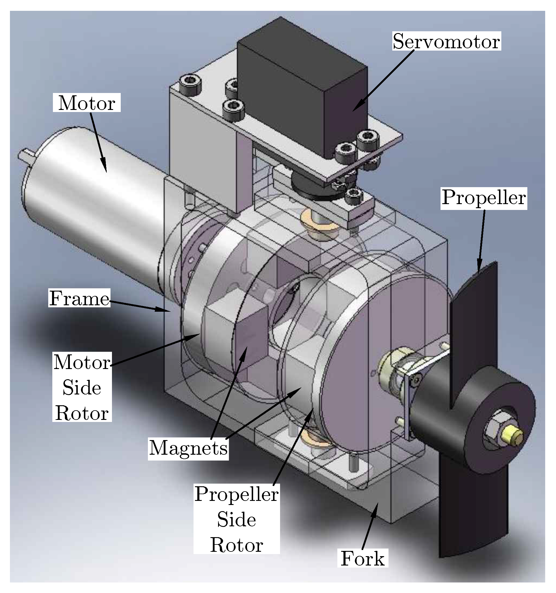
In [65] (2016, Figure 15), the RMCT concept presented in [5,51] receives a new non-submersible prototype, using now a flat reconfigurable magnetic coupling (F-RMC) or joint, also with one actuator to assure 1-DOF of reconfiguration.
In [56] (2017, see Figure 8a), the SUR-II evolves to the SUR-III, now with four three pumped-water-jet-based RT, each one with 2-DOF of reconfiguration, using waterproof servo-motors.
Robots with torpedo-shaped hulls are proposed in [64,66,67] (see Figure 14b and Figure 16). They are equipped with propeller-based RTs, with 2-DOF of reconfiguration, using a different type of spherical joints. The difference between them is in the reconfiguration mechanism. In [67] (2019), a parallel mechanism with three actuators is necessary for controlling two more DOF, as in [27,58]. In [64] (2016, see Figure 14b), 2-DOF of reconfiguration are added using only two actuators, as in [57,62], but this time using an spherical robotic wrist joint proposed in [68,69].
- They do not need to reorient their motor axis to reconfigure the thrust vector. Only their propeller, duct or nozzle have to be reoriented. Thus, reduced power and torque values are required in manoeuvrers.
- They need mechanical seals since the movement is transmitted through shafts or rods, which implies frictions and likely water-tightness issues.
In fact, the water-tightness issue is not addressed in these above-mentioned RT proposals. The water-tightness issue is most critical in deep-water tasks due to high pressure. However, there exist full water-tightness solutions available with wide reconfiguration angles. One of these most promising RT solutions is found in [70] (2016), where a rim-driven propulsion pod is equipped with pitch-variable blades, which can reach the best propeller performance for a range of hull speeds, and not for only one. Moreover, its blades rotate thanks a rotating magnetic field that crosses a non pierced thruster hull, keeping the motor sealed hermetically.
Together with this latter solution, RT proposals based on reconfigurable magnetic couplings are the most promising in terms of water-tightness. In these thrusters, the motor shaft movement is transmitted to the propeller one at a distance, also without any material medium, through a magneto-mechanical device which works as a coupling or joint allowing the propeller driving and orientation. Besides its water-tightness, this technology brings many other benefits such as:
- Movement transmission between insulated environments (fluids, heat, radiations)
- Complicated and unsure mechanical seals are no longer needed for rotating joints
- Robot water-tightness is not jeopardised by a hull breach
- Elimination of the friction inherent to mechanical seals of rotary joints
- Transmission protection in case of severe load peaks (where a gearbox would break), since it works as a torque limiter (mechanical fuse).
- Flexible joint with a spring effect that can mitigate eventual vibrations and shakes
- Low maintenance when it is compared to a mechanical coupling or joints (such as Universal, Rzeppa, and Tripod one)
- Their rotors are synchronous in steady-states when the magnetic field is generated only by magnets in both rotors, and not by electric currents as in [71]
The usage of magnetic coupling to ensure the water-tightness of FT systems is not new [72,73]. The novelty in RMCT [51] is the use of reconfigurable magnetic couplings to construct feasible RTs.
As discussed, RTs are endowed with at least 2-DOF of actuation, which means the thrust vector can be contained in a plan. Figure 17 shows a section view of a 2-DOF RMCT [61].
The good point of this solution is the usage of conventional magnetic couplings (axial or radial). The drawback is that all the thruster is reconfigured, which implies more inertia and energy to the reconfiguration, as better discussed previously.
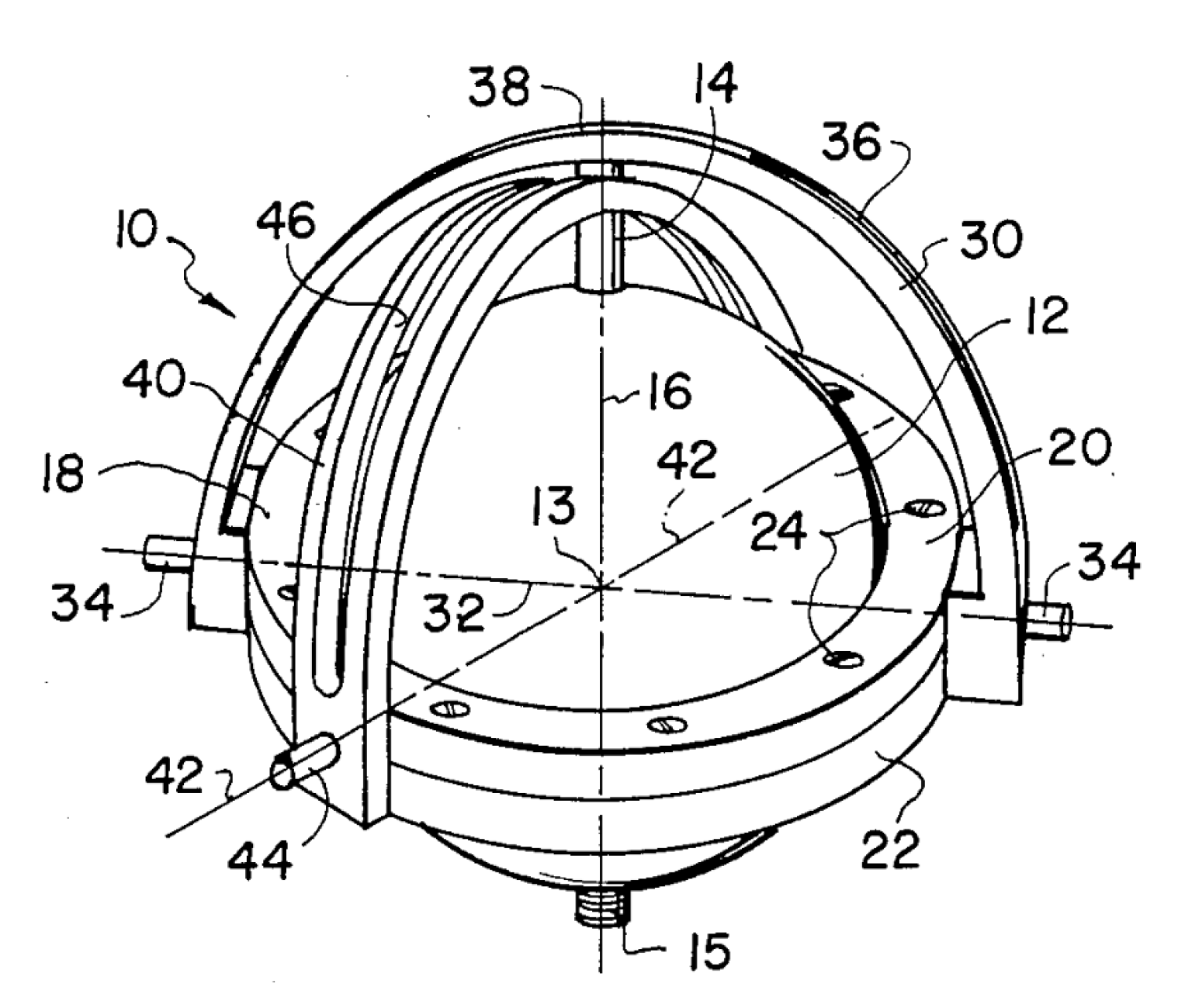
Another more complex possibility is the inclusion of a supplementary DOF, designing a 3-DOF RMCT. A possible mechanical solution for this device is the assembling of two conventional magnetic couplings orthogonally arranged, which leads to a spherical wrist joint [69] as in Figure 18.
Figure 12 and Figure 15 shows the first spherical-RMCT, and the first flat-RMCT, respectively. In both figures, it is possible to see that both proposals are non-submersible. The challenge in making submersible 3-DOF RT prototypes is the difficulty of implementing two mechanical functions, jointly: the transmission torque function (coupling) at a distance with the hull in between, and the 3D rotational freedom (spherical joint). For a better understanding of this problematic, a further understanding of these reconfigurable magnetic couplings is crucial.
4. Advances in Reconfigurable Magnetic Couplings
A magnetic coupling (MC) is one among other devices that runs thanks to the magnetic coupling phenomenon. It is interesting noting fundamental differences from motors and magnetic gears. All these devices have rotating magnetic fields. Typically, there are two coupled rotating magnetic fields: a driver and a driven one.
As motors, regarding the speed, there are synchronous magnetic couplings and asynchronous magnetic couplings. If both rotors have permanent magnets, rotors speeds are synchronous in steady-state. For an asynchronous behaviour, rotors are different, where one has a constant magnetic field (usually from permanent magnets), and a magnetic field is induced in the driven or driver rotors due to eddy-currents [71]. These currents are only generated if there is a different speed (slip) between rotors, similarly to asynchronous motors. To promote higher eddy-currents, the eddy-current carrying rotor is typically made in copper. However, due to these currents, this asynchronous option is lossy since it generates Ohmic heating.
Due to the asynchronous aspect of eddy-currents and hysteresis couplings, they are also applied in clutches, and due to their power dissipation, they are also applied in brakes [74,75,76].
Another manner to differentiate MCs comes from the air-gap or magnetic flux geometries since one generally involves the other. Their air-gap geometries are typically plane or cylindrical [77]. However, most of the time, MCs are classified regarding their magnetic flux geometries, which are usually classified as axial or radial [78]. An MC with axial magnetic flux usually has a plane air-gap, and an MC with a radial magnetic flux usually has a cylindrical air-gap. Axial magnetic couplings (AMC) are also referred as face-to-face MC [79], or flat MC [65]. Radial magnetic couplings (RMC) are also referred as coaxial MC [80], or concentric MC.
From the ideas in [81,82,83,84], the engineering and applications of MCs have evolved a lot. Nowadays, it is possible to understand better what are the characteristics that make great AMC and RMC, as examples in Figure 19 and Figure 20, respectively, that will be further presented and discussed below.
It is possible to find many different ideas that tried to improve MC performances along this last century. One of the most promising ideas was the magnetic flux guidance by soft-iron yokes, as in [85], which concentrate the magnetic field energy at the air-gap between rotors. Improvements were also achieved by the rotors dissymmetry or “short pitch” magnets, as in [86,87]. However, the best idea until now, comes with a “magnetic curiosity” discovered in [88] and after in [89], which nowadays is known as Halbach arrays.
Halbach arrays can do the same than soft-iron yokes, but using magnets, and so constitutes an ironless alternative. The discovered pattern has affected many different devices, and it is possible to see its application on RMCs with magnets parallelepiped in [90,91]. Moreover, in [92] it is shown that MCs can be still more optimised if their magnets sizes are well-chosen in the arc-shaped magnets based rotors with Halbach arrays, which can result in a non-sinusoidal torque behaviour.
Usually, the parameter that evaluates the performance of an MC is the ratio of maximum transmissible torque over magnets volume or mass. It is also called magnetic torque density analysis [93]. In [80], the torque density optimisation problem is addressed for AMC and RMC, using soft-iron yokes as flux closure for arched magnets. In [94], ironless arched magnets arrangements are investigated for bearings and magnetic couplings by simplified formulas, to calculate forces and stiffness based on coupling energy between elementary dipoles. In [95], an approximate analytical expression is derived based on the Amperean Model, and the torque density is optimised for an ironless axial arched magnetic coupling. In [96], magnets arrays are optimised using FEA (Finite Element Analysis), for finding the best magnetisation direction of elements in a grid, which result in the Halbach array. In [97], parameters that affect arched axial magnetic couplings with iron yokes are also studied by 3D FEA. In [78], it is proposed a new analytical formulation using a subdomain method and the torque density optimised by Genetic Algorithms (GA). Recently, in [98,99], it is proposed what is called as “ideal” AMC and RMC, with rotors made from arc-shaped magnets in Halbach arrays, and their torque density analyses are based on a new analytical formulation, including the curvature effects that were neglected in [78]. However, here, it is considered that they cannot be “ideals” if the results in [92] are not applied.
At this point, it is essential to remark that, even more than forty years after publications of ideas in [88,89], there are still some initiatives trying to optimise magnetic couplings without addressing their pattern.
Without Halbach array or soft-iron yokes, the magnetic flux is dispersed in both rotors sides (as in [94,95], for example). However, the usage of soft-iron yokes increases rotors volume, mass, and inertia, which reduces torque and stiffness densities (e.g., in [78,80,97]). Another problem with soft-iron yokes is the volume increase of metallic conductors, where can be generated eddy-currents, which creates a damping effect because of energy losses in transient conditions, which is only useful for asynchronous couplings.
In an ideal Halbach arrangement, the maximum concentration of the magnetic field in the rotors air-gap is achieved when the magnetisation vectors change continuously from a pole to another. However, for technological reasons, the rotor ring is subdivided into separate magnets with a determined and predominant magnetisation vector direction. It is sometimes called the discretisation of ideal Halbach [100].
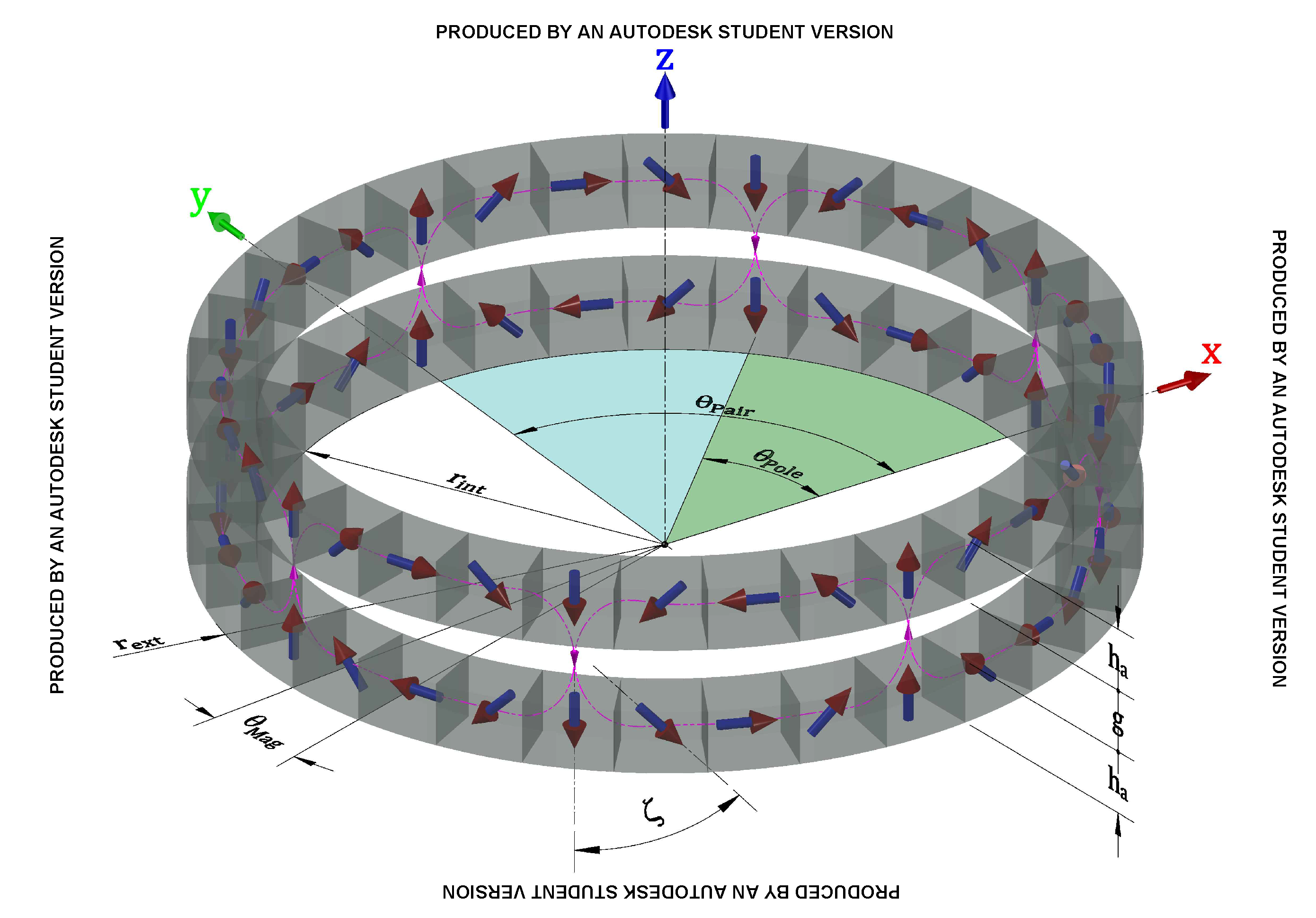
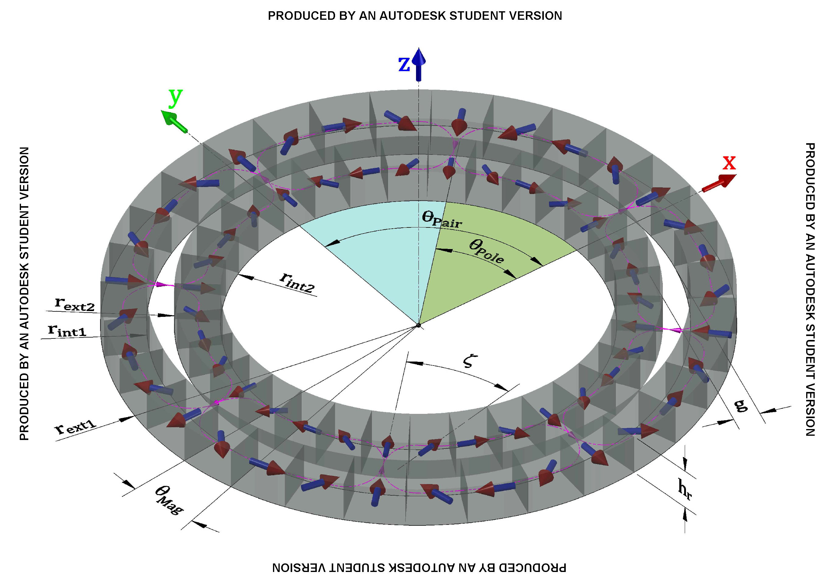
Figure 19 and Figure 20 present Halbach array-based AMC and RMC, with arched magnets. It is necessary to know a set of parameters to define these MCs:
- the inner radii, , ,
- the outer radii, , ,
- the height of rotors, ,
- the air-gap height, g
- the poles-pairs, p per rotor
- the Halbach stage index,
- the remnant magnetic flux density, or magnetic remanence,
- the magnetic permeability of magnets,
- the magnets material density,
It is necessary to define angular positions to know the configuration of rotors. So, is the angular position of the motor side rotor around the fixed axis z, while or is the same but for load side rotor. When rotors are aligned, i.e., , as shown in Figure 19 and Figure 20, it sets-up a neutral configuration where there is no torque acting on rotors. In this configuration, it is also verified the maximum attraction between rotors (). To create a torque between rotors, it is necessary to create a misalignment between them, with . This behaviour makes the magnetic coupling working as a non-linear torsional spring, which allows naming the difference between and as the magnetic spring angle [101]. Sometimes, is defined as the relative mechanical displacement angle [102].
The intrinsic flexibility of MCs can be a benefit or a drawback depending on the application. It is a benefit when it allows misalignment between driver and driven rotors axes. Moreover, it can mitigate eventual vibrations and shakes. However, for precise application, a drawback of this MCs is its relatively low stiffness, which introduces speed/position oscillations and therefore, inaccuracy [103]. When an MC connects two rotors (two inertia), transmitting driver movement (motor side) to a driven rotor (load side), a low coupling stiffness does not assure a transiently synchronous movement between them [102,104,105]. In [106] it is referred to as the “stiffness problem”, which can affect any system with compliant coupling.
Some techniques to control these flexibly coupled systems exist [103,107,108]. The stiffness optimisation of AMCs is dealt in [93], which makes easier and more accurate the speed/position control task, when it is needed.
Reconfigurable magnetic couplings (RMC) are MCs that assure torque transmission for a considerable angle between driver and driven concurrent axes. As discussed above, the RMC concept was introduced in [51], and the first prototype, i.e., the spherical RMC, was presented in [5], with a reconfiguration angle range equal to . Figure 21 shows S-RMC rotors simulations, where magnetic fluxes are shown for two configurations.
At the left of Figure 21, top and front view of rotors magnetic fluxes are shown for a configuration where the driver and driven axes are parallels, but for a magnetic spring (shift) angle . Parts coloured in yellow and red are magnets, which are sources of magnetic field, and so magnetic fluxes. Parts coloured in green are made by soft ferromagnetic materials (“irons”). The magnetic fluxes enter and exit rotors by these soft parts. Since , there is an attraction torque between rotors, which tries to align the inner rotor limbs (spherical ends of the inner rotor cross) to the outer rotor green polar parts, which in turn reduces the reluctance to the fluxes passage.
At the right of Figure 21, top and front view of rotors magnetic fluxes are shown for a reconfigured position, where the driver and driven axes are concurrent with a reconfiguration angle non-null, and with a magnetic spring angle . In this reconfigured position, it is possible to see magnetic fluxes more dispersed than those of the not-reconfigured one, which indicates a reduction of torque from 230 to (as verified in experiments).
The first great thing in S-RMC is the materialisation of a contactless spherical joint. The second innovative thing is that S-RMC is a reconfigurable reluctance magnetic coupling, with magnets only in the outer rotor. From this point of view, it is interesting to analyse how S-RMC technology seems similar to those of spherical motors, which have been developed since [109].
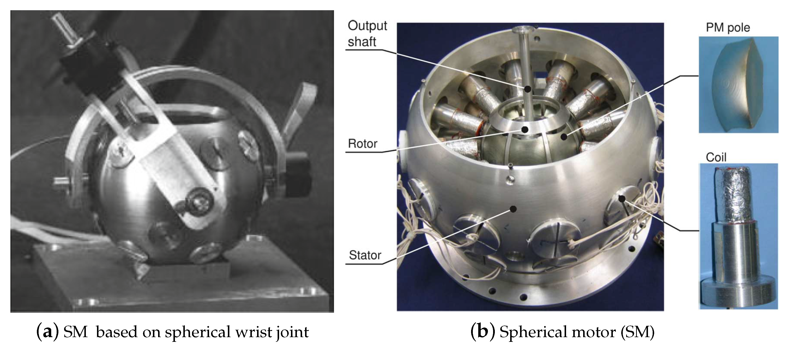
Analysing spherical motors technologies in [110] (see Figure 22), it is possible to identify other benefits of S-RMC solution. Taking into account the differences above-discussed between motors and MCs (motors have one stator and one rotor, against two rotors in MCs), S-RMC solution simplifies the electromagnetomechanical problem of spherical motors into a magnetomechanical one. It is obtained since in S-RMC the driven magnetic field is generated by mechanical rotation of the outer rotor, which is mounted with permanent magnets. Of course, S-RMC has more inertia since it is equipped with two rotors. In spherical motors, the driven magnetic field is generating by pulsating electric currents, which present torque oscillations (torque ripple). Moreover, their electric currents are generated usually by coils, which implies Ohmic losses. Thus, S-RMC is a no-current, wireless, permanent magnet-based synchronous solution, which can reconfigure the movement from advanced conventional electric motors, or even from a combustion motor.
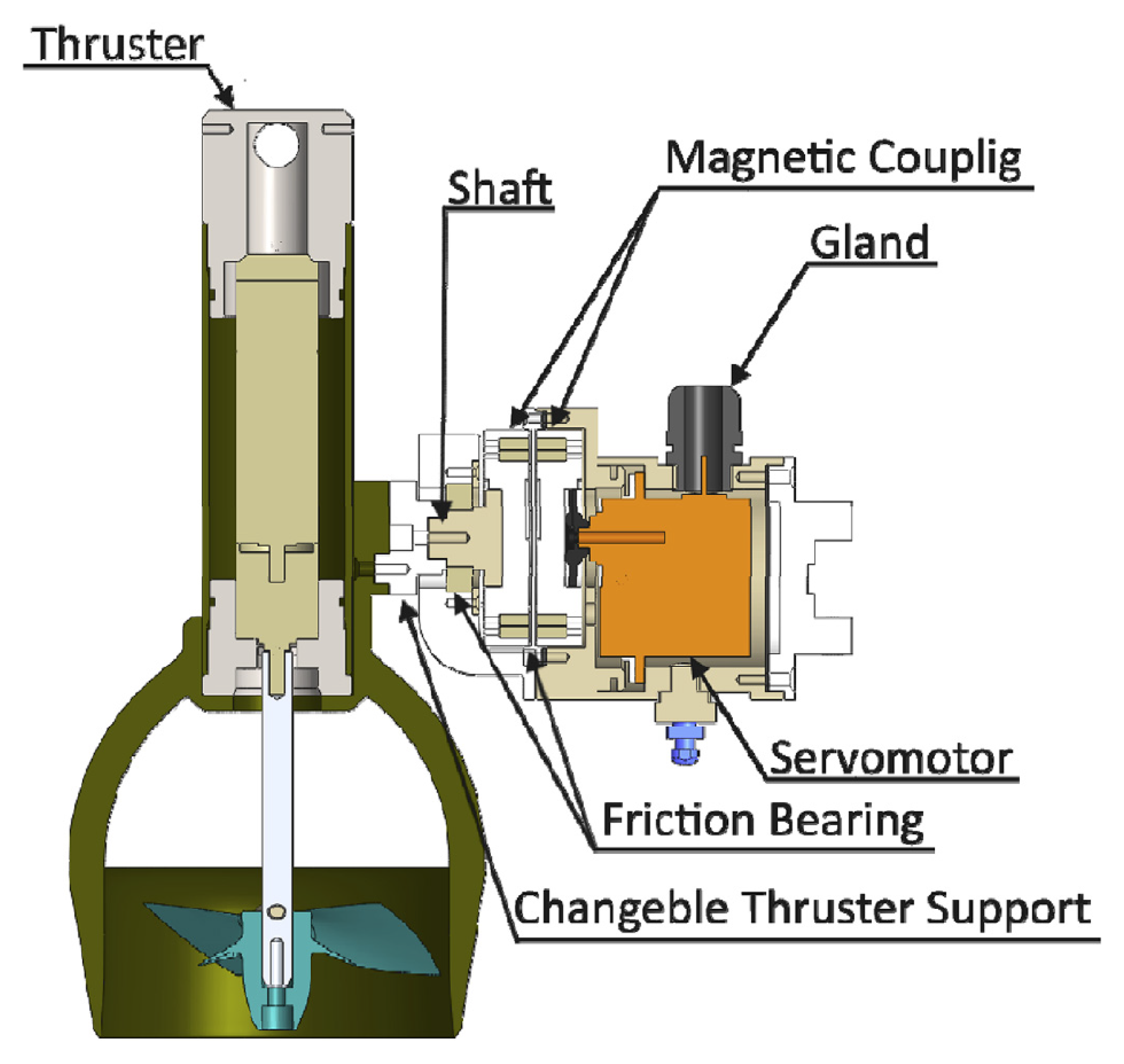
The RMC design has been improving. These improvements have focused on increasing the magnetic coupling torque in intensity and quality. A second proposal for an RMC is introduced in [65]: the Flat-RMC (F-RMC). Figure 23 shows Flat-RMC. F-RMC is designed to present a better maximum transmissible torque than S-RMC. It is possible since its rotors are equipped with magnets.
The F-RMC solution has geometric similarities with the spherical joint presented in [113], which has literately a sphere that defines the movement constraint between two axial magnetic rotors. The difference in F-RMC is that the spherical movement constraint is defined by bearing blocks that are not in the joint centre. F-RMC uses two parts of conventional axial MCs with flat shaped magnets (parallelepipedal), which have a easier fabrication.
Figure 23 shows the magnetic parts without their non-magnetic protection cover against water (jackets).
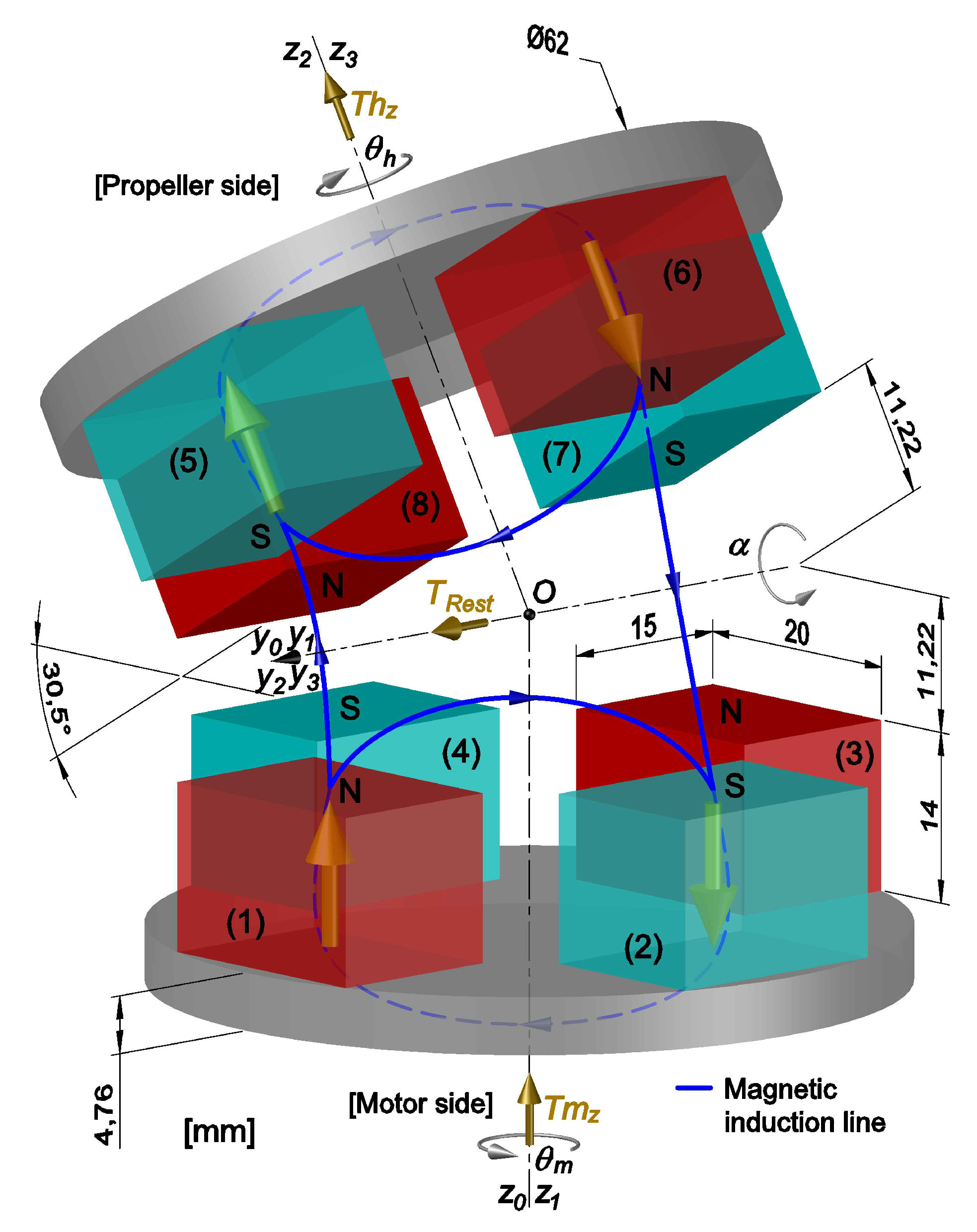
Naturally, the quantity and material type of magnets affect the coupling torque values. It has eight equal magnets placed ninety degrees between each other. The magnets coloured in blue have their south pole facing the air gap, and the red ones are in the other way. Both soft-iron yokes of rotors are made of magnetic stainless steel. The blues lines indicate the two more important magnetic induction lines (and flux): the circuit between two magnets in the same part (e.g., magnets (1) and (2)), and a bigger circuit including four magnets, two on each side (e.g., magnets (1), (2), (5) and (6)).
In Figure 23, the coupling is shown with its maximum reconfiguration angle, °, when magnets (4) and (8) are closest and magnets (2) and (6) are farthest, and with °, i.e., when the magnets on motor side are aligned with those on propeller side: stable state with the minimum magnetic reluctance (MMR). It is important to point out that the torque transmission capacity is highly sensitive to any air gap change. In the configuration of Figure 23, the maximum transmissible torque is around and for ° this torque falls for around .
A further torque analysis of this F-RMC is addressed in [101]. It states that, when ° we have classical magnetic couplings (parallel rotors axes). In this condition, if ° (null magnetic spring torque), the magnets faces of a rotor are parallels to those of the other rotor, with the same air gap between all exposed faces of magnets. Hence, the attraction and repulsion forces between magnets around the reconfiguration axis (servomotor axis) are balanced between each side, and there is no torque around this axis (but there is an axial attractive force). However, the configuration with ° is unstable because if ° (even is small) the attraction force between magnets (4) and (8) is greater than the attraction force between magnets (2) and (6), thus there is a positive torque around axis , which tends to increase further . In this case, to keep and control , the servomotor (Figure 15) has to apply a counter torque, which is called restoring torque in Figure 23 ( in [65]). A drawback of this version is its high that has to be counterbalanced by the servomotor: its value is almost equal to the maximum transmitted torque.
A third proposal for an RMC is introduced in [114]: the Radial-RMC (R-RMC), shown in Figure 24a,b. The R-RMC is the reconfigurable version of the conventional RMC, as presented in Figure 20. Some advances in the R-RMC concept over the F-RMC one are:
- the elimination of the high attractive force between rotors
- the reduced restoring torque
- the reduced auto-driving effect when axisymmetric rotors are assured
The R-RMC concept is still in development and until now a real prototype was not presented.
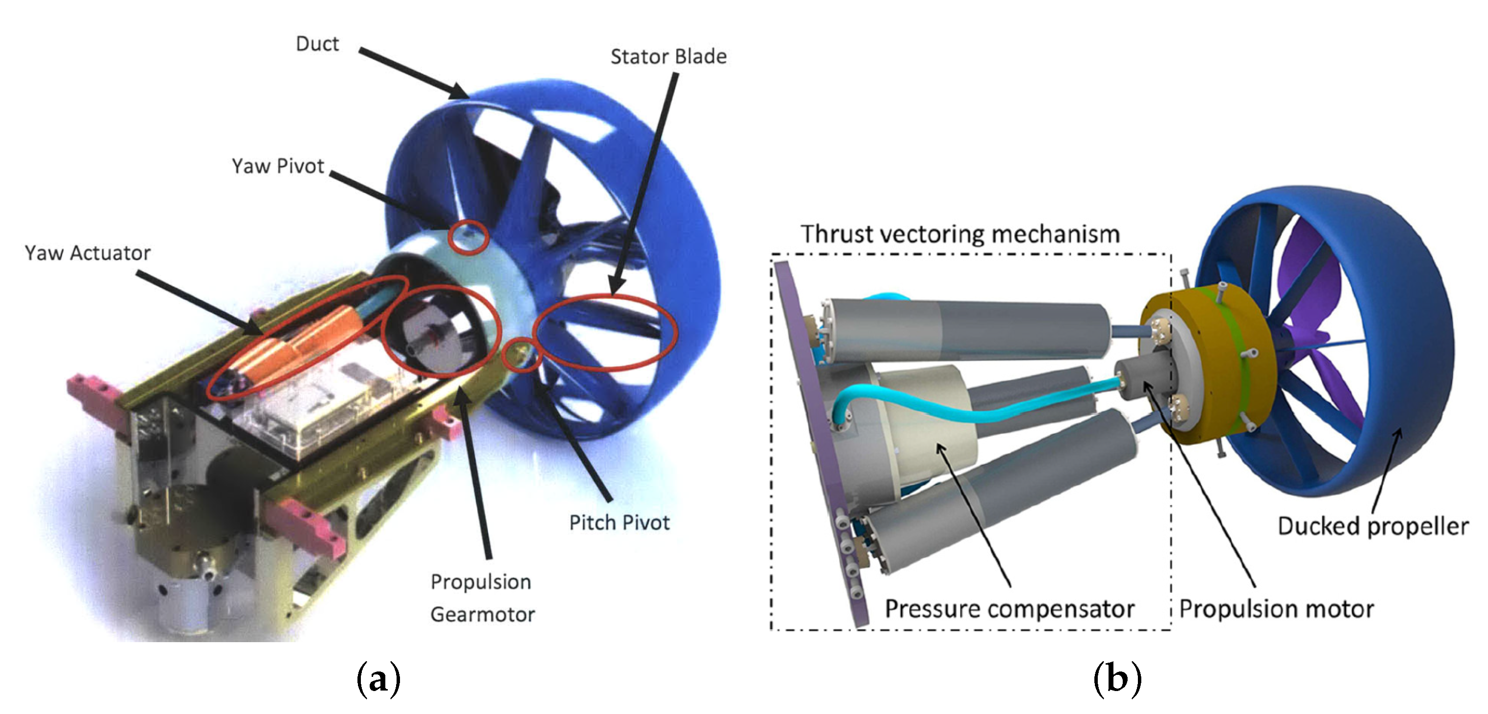
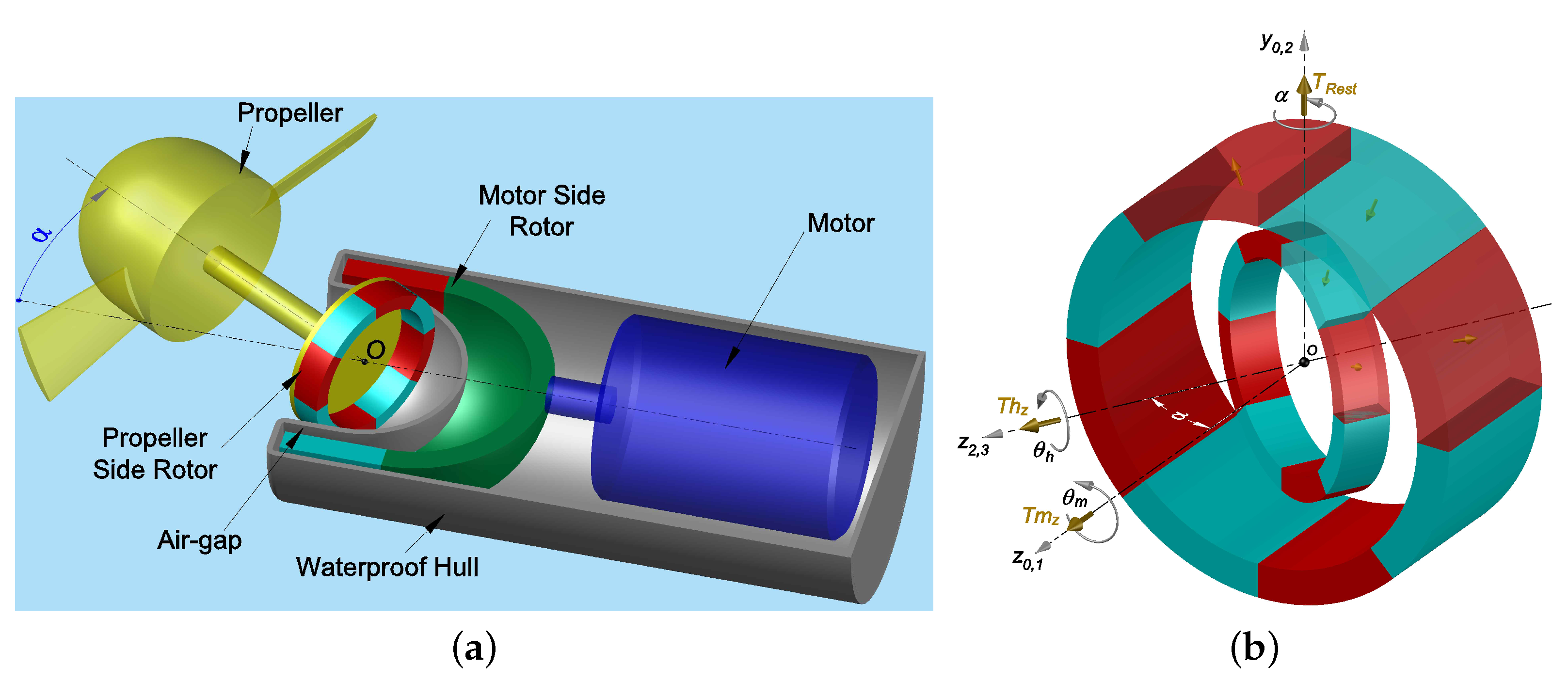
More recently, in [115] a new underwater robot was proposed using a pumped-water-jet primary thruster assisted by two auxiliary S-RMCT, each one dotted with 3-DOF (Figure 25a). This S-RMCT is also based on the spherical robotic wrist joint presented in [68,69] (Figure 18), which was also used in the proposals of Figure 14b ([64]) and Figure 22a ([112]). The main differences between the S-RMCT in [115] and that one in [5] are:
- the new inner rotor that is also equipped with magnets, which increases the maximum coupling torque
- the new magnets presents a more complex geometry, sector of cylinders or spheres, which make the new thruster more expensive
The main drawback in this new version is the usage of water-proof servomotors (Figure 25b), as in the proposal of RT in Figure 8, which are technologies limited in terms of depths. However, the increase of efforts on the development of new RMCTs shows that we are not so far from a viable prototype really full water-proof.
5. Summary and Conclusions
In the presented review, it is clear how the humankind keeps applying great efforts in the exploration of the Earth, with its forests, oceans, and ice-lands, but also in exploring other planets, looking for new life forms in extraterrestrial oceans.
In last years, a considerable quantity of research energy was applying on seeking the increase of the AUVs manoeuvrability. Most of them are concentrated in reconfigurable vectorial thrusters and bioinspired or biomimetic propulsion architectures. It is possible to find promising examples using both approaches. However, it is still missing a fair comparison between these two technologies, which should include the last advances in both, not excluding novel solutions in reconfigurable vectorial thrust.
The last advances in reconfigurable vectorial thrusters are concentrated in two groups: pumped-water-jet and propeller-based systems. Techniques to change the thrust vector are usually in changing the orientation of propellers axes, ducts or nozzles. However, there are examples where all thruster or pump is rotated. When the water-jet comes from a constant pressure pump, the intensity jet cannot sometimes be controlled, which reduces 1-DOF of control per thruster. The proposals can assure 1 or 2-DOF of vector reconfiguration, using 2, 3 or 4 actuators, usually applied in parallel mechanisms. The most promising mechanism seems to be a spherical robotic wrist joint developed in the 1980s, which demands only one actuator for each degree of freedom added. The identified reconfiguration ranges variate from to . A great solution was patented in 2016, which is a reconfigurable rim-driven magnetic-coupled solution, equipped with adaptable pitch blades. However, it has a drawback: the motor mass is also reoriented in the reconfiguration. Moreover, the watertight of the reconfiguration mechanism is not addressed.
The advances in rotational magnetic couplings was surveyed. The best examples in literature have arc-shaped magnets, organised in Halbach arrays with different magnets sizes, and do not present soft ferromagnetic yokes. They are usually optimised regarding their volumetric magnetic torque density. Two main topologies of Halbach array-based magnetic coupling were detailed introduced: axial and radial. The intrinsic flexibility of magnetic couplings was discussed. It can be a benefit where there exist misalignment or vibrations, but introduces the stiffness problem, which in turn makes hard the position control task. The advances in reconfigurable magnetic coupling was also presented. This technology was compared with solutions given by spherical motors development. The main advantage is that reconfigurable magnetic couplings eliminate the electricity of the electromagnetomechanical problem in spherical motors, transforming it in a simpler magnetomechanical system. It is possible because the motor stator, with its pulsating rotational field, is replaced by another magnets-based rotor. The spherical, flat, and radial existing concepts and some existing prototypes were presented. The last one, presented on 2019, is a spherical great example, but it also uses waterproof servomotors limited in terms of depths. An idea is transmitting the degrees of freedom of servomotors also using magnetic couplings, as in a solution present in pivoted thrusters.
Finally, the 3-DOF reconfigurable magnetic coupling thruster is a promising concepts that must be converted into viable submersible prototypes with full waterproof mechanisms.
Author Contributions
Investigation, H.F.G. and O.C.; Writing—Original Draft Preparation, H.F.G.; Writing—Review & Editing, O.C., H.F.G., M.B. and P.S.M.; Supervision, O.C., M.B. and P.S.M.; Project Administration, O.C., M.B.; Funding Acquisition, P.S.M. and O.C. All authors have read and agreed to the published version of the manuscript.
Funding
This research was funded by CSF-PVE-S Program/CAPES/BRAZIL grant number 88887.116973/2016-00.
Institutional Review Board Statement
Not applicable.
Informed Consent Statement
Not applicable.
Data Availability Statement
Not applicable.
Conflicts of Interest
The funders had no role in the design of the study; in the collection, analyses, or interpretation of data; in the writing of the manuscript, or in the decision to publish the results.
Abbreviations
The following abbreviations are used in this manuscript:
| AUV | Autonomous underwater vehicles |
| COT | Cost of transport |
| DOF | Degree of freedom |
| FT | Fixed thruster |
| MER | Marine renewable energy |
| RMC | Reconfigurable magnetic coupling |
| RMCT | Reconfigurable magnetic coupling thruster |
| ROV | Remotely operated underwater vehicles |
| RT | Reconfigurable thruster |
| SM | Spherical motor |
| SUR | Spherical underwater robot |
| TTURT | Tilt thrusting underwater robot |
| UR | Underwater robot |
| VT | Vectorial thruster |
References
- Rhian, J. Martian Evolution: From Sojourner to Curiosity—A Legacy. Mars Q. 2013, 4, 5–6. [Google Scholar]
- Breakthrough Initiatives. Internet Investor and Science Philanthropist Yuri Milner & Physicist Stephen Hawking Announce Breakthrough Starshot Project to Develop 100 Million Mile per Hour Mission to the Stars Within a Generation. 2016. Available online: http://breakthroughinitiatives.org/News/4 (accessed on 4 February 2021).
- Tabor, A. What Is SUBSEA? 2018. Available online: https://www.nasa.gov/ames/subsea (accessed on 4 February 2021).
- Gao, F.D.; Han, Y.Y.; Wang, H.D.; Xu, N. Analysis and innovation of key technologies for autonomous underwater vehicles. J. Cent. South Univ. 2015, 22, 3347–3357. [Google Scholar] [CrossRef]
- Chocron, O.; Prieur, U.; Pino, L. A validated feasibility prototype for AUV reconfigurable magnetic coupling thruster. IEEE/ASME Trans. Mechatron. 2014, 19, 642–650. [Google Scholar] [CrossRef]
- Murphy, A.J.; Haroutunian, M. Using bio-inspiration to improve capabilities of underwater vehicles. In Proceedings of the 17th International Unmanned Untethered Submersible Technology Conference, Portsmouth, NH, USA, 11–24 August 2011. [Google Scholar]
- Vega, E.P.; Chocron, O.; Ferreira, J.V.; Benbouzid, M.E.H.; Meirelles, P.S. Evaluation of AUV Fixed and Vectorial Propulsion Systems with Dynamic Simulation and Non-linear Control. In Proceedings of the IECON2015, Yokohama, Japan, 9–12 November 2015; pp. 944–949. [Google Scholar]
- RTsys. COMET 300 AUV. Available online: https://rtsys.eu/wp-content/uploads/2021/01/COMET_300_Briefsheet_003.pdf (accessed on 4 February 2021).
- RTsys. NemoSens: Micro Autonomous Underwater Vehicle. Available online: https://pdf.nauticexpo.fr/pdf-en/rtsys/comet-300-auv/50414-113779.html (accessed on 4 February 2021).
- Eca Group. A9-E/AUV/Autonomous Underwater Vehicle. Available online: https://www.ecagroup.com/en/solutions/a9-e-auv-autonomous-underwater-vehicle (accessed on 4 February 2021).
- Eca Group. A9-M/AUV/Autonomous Underwater Vehicle. Available online: https://www.ecagroup.com/en/solutions/a9-m-auv-autonomous-underwater-vehicle (accessed on 4 February 2021).
- Eca Group. A18D/AUV/Autonomous Underwater Vehicle. Available online: https://www.ecagroup.com/en/solutions/a18-d-auv-autonomous-underwater-vehicle (accessed on 4 February 2021).
- Eca Group. A18-E/AUV/Autonomous Underwater Vehicle. Available online: https://www.ecagroup.com/en/solutions/a18-e-auv-autonomous-underwater-vehicle (accessed on 4 February 2021).
- Eca Group. A18-M/AUV/Autonomous Underwater Vehicle. Available online: https://www.ecagroup.com/en/solutions/a18-m-auv-autonomous-underwater-vehicle (accessed on 4 February 2021).
- Eca Group. A27-M/AUV/Autonomous Underwater Vehicle. Available online: https://www.ecagroup.com/en/solutions/a27-m-auv-autonomous-underwater-vehicle (accessed on 4 February 2021).
- Möller, M.P.; Schappi, A.; Buholzer, P.; Wegmann, M.; Seewer, A.; Dubois, F.; Flury, J.F.; Freiermuth, V.; Heslinga, M. Focus Project Sepios: Riding the Wave of Progress; Technical Report; ETH Zürich: Zürich, Switzerland, 2014. [Google Scholar]
- Yu, J.; Su, Z.; Wu, Z.; Tan, M. Development of a Fast-Swimming Dolphin Robot Capable of Leaping. IEEE/ASME Trans. Mechatron. 2016, 21, 2307–2316. [Google Scholar] [CrossRef]
- Wu, Z.; Yu, J.; Yuan, J.; Tan, M. Towards a gliding robotic dolphin: Design, modeling, and experiments. IEEE/ASME Trans. Mechatron. 2019, 24, 260–270. [Google Scholar] [CrossRef]
- Boyer, F.; Chablat, D.; Lemoine, P.; Wenger, P. The EEL-Like Robot. In Proceedings of the ASME 2009 International Design Engineering Technical Conferences and Computers and Information in Engineering Conference, San Diego, CA, USA, 30 August–2 September 2009; pp. 1–8. [Google Scholar]
- Yu, J.; Zhang, C.; Liu, L. Design and Control of a Single-Motor-Actuated Robotic Fish Capable of Fast Swimming and Maneuverability. IEEE/ASME Trans. Mechatron. 2016, 21, 1711–1719. [Google Scholar] [CrossRef]
- Pollard, B.; Tallapragada, P. An Aquatic Robot Propelled by an Internal Rotor. IEEE/ASME Trans. Mechatron. 2017, 22, 931–939. [Google Scholar] [CrossRef]
- Eca Group. AUV—ALISTAR 3000. Available online: https://www.ecagroup.com/en/solutions/alistar-3000-auv-autonomous-underwater-vehicle (accessed on 4 February 2021).
- Mohseni, K. Pulsatile vortex generators for low-speed maneuvering of small underwater vehicles. Ocean Eng. 2006, 33, 2209–2223. [Google Scholar] [CrossRef]
- Geng, L.; Hu, Z.; Lin, Y. Hydrodynamic characteristic of synthetic jet steered underwater vehicle. Appl. Ocean Res. 2018, 70, 1–13. [Google Scholar] [CrossRef]
- Thales. Première Mondiale: Thales et 19 PME Françaises Inventent un Concept de Drone Mixte de Surface et Sous-Marin. 2016. Available online: https://www.thalesgroup.com/sites/default/files/database/d7/asset/document/cp_20161017_thales_et_19_pme_inventent_un_concept_de_drone_mixte_de_surface_et_sous-marin_fr_0.pdf (accessed on 4 February 2021).
- Chocron, O.; Delaleau, E. Trajectory-Based Synthesis of Propulsion Systems for Fixed-Thrusters AUVs. In CISM International Centre for Mechanical Sciences, Courses and Lectures; Springer International Publishing: New York, NY, USA, 2019; Volume 584, pp. 380–391. [Google Scholar] [CrossRef] [Green Version]
- Cavallo, E.; Michelini, R.C.; Filaretov, V.F. Conceptual design of an AUV equipped with a three degrees of freedom vectored thruster. J. Intell. Robot. Syst. Theory Appl. 2004, 39, 365–391. [Google Scholar] [CrossRef]
- Nokin, M. Victor 6000—A deep teleoperated system for scientific research. In Proceedings of the Oceans Conference Record (IEEE), Halifax, NS, Canada, 6–9 October 1997; Volume 1, pp. 167–171. [Google Scholar] [CrossRef]
- Eca Group. A18-TD/AUV/Autonomous Underwater Vehicle. Available online: https://www.ecagroup.com/en/solutions/a18-td-auv-autonomous-underwater-vehicle (accessed on 4 February 2021).
- CHASING-INNOVATION, Co.Ltd. CHASING F1 Fish Finder Drone_Wireless Underwater Fishing Camera—Chasing Innovation. Available online: https://www.chasing.com/chasing-f1.html (accessed on 4 February 2021).
- CHASING-INNOVATION, Co.Ltd. CHASING M2 ROV|Professional Underwater Drone with a 4K UHD Camera—Chasing Innovation. Available online: https://www.chasing.com/chasing-m2.html (accessed on 4 February 2021).
- CHASING-INNOVATION, Co.Ltd. CHASING|CHASING DORY—The world’s Most Portable Underwater Drone—Chasing Innovation. Available online: https://www.chasing.com/chasing-dory.html (accessed on 4 February 2021).
- CHASING-INNOVATION, Co.Ltd. CHASING|GLADIUS MINI—4K Underwater Drone with Camera—Chasing Innovation. Available online: https://www.chasing.com/gladius-mini.html (accessed on 4 February 2021).
- PowerVision Inc. PowerRay Underwater Drone|Explore the Underwater World. Available online: https://www.powervision.me/en/product/powerray (accessed on 4 February 2021).
- Kaya, K.D.; Goren, A.; Yilmaz, S.; Bayramoğlu, K. Determination of operating parameters of an AUV following a preplanned trajectory using hydrodynamic analysis data. Ocean Eng. 2020, 217, 107708. [Google Scholar] [CrossRef]
- Loc, M.B.; Choi, H.S. Design of self-tuning gain depth controller for an autonomous underwater vehicle with mass shifter mechanism. In Proceedings of the 12th International Conference on Control, Automation and Systems, JeJu Island, Korea, 17–21 October 2012; pp. 1742–1746. [Google Scholar]
- Williams, A. Design of a Low-Cost Open-Source Underwater Glider; Technical Report. 2018. Available online: https://engrxiv.org/kvqmh/ (accessed on 4 February 2021). [CrossRef]
- Nguyen, N.D.; Choi, H.S.; Lee, S.W. Robust Adaptive Heading Control for a Ray-Type Hybrid Underwater Glider with Propellers. J. Mar. Sci. Eng. 2019, 7, 363. [Google Scholar] [CrossRef] [Green Version]
- Zhou, H.; Fu, J.; Liu, C.; Zeng, Z.; Yu, C.; Yao, B.; Lian, L. Dynamic modeling and endurance enhancement analysis of deep-sea gliders with a hybrid buoyancy regulating system. Ocean Eng. 2020, 217, 108146. [Google Scholar] [CrossRef]
- Wu, H.; Niu, W.; Wang, S.; Yan, S. Prediction method of permissible error ranges of control parameters for underwater gliders under given operation accuracy. Appl. Ocean Res. 2020, 103, 102153. [Google Scholar] [CrossRef]
- Le Mézo, T.; Le Maillot, G.; Ropert, T.; Jaulin, L.; Ponte, A.; Zerr, B. Design and control of a low-cost autonomous profiling float. Mech. Ind. 2020, 21, 512. [Google Scholar] [CrossRef]
- Antonelli, G.; Chiaverini, S.; Sarkar, N.; West, M. Adaptive control of an autonomous underwater vehicle: Experimental results on ODIN. In Proceedings of the 1999 IEEE International Symposium on Computational Intelligence in Robotics and Automation, Monterey, CA, USA, 8–9 November 1999; pp. 64–69. [Google Scholar] [CrossRef]
- Choi, H.T.; Hanai, A.; Choi, S.K.; Yuh, J. Development of an Underwater Robot, ODIN-III. In Proceedings of the IEEE International Conference on Intelligent Robots and Systems, Las Vegas, NV, USA, 27–31 October 2003; Volume 1, pp. 836–841. [Google Scholar] [CrossRef]
- Department of Aerospace & Mechanical Engineering UUV Project. Autonomous Unmanned Underwater Survey Vessel UUV AUV—iRobot Seaglider. Available online: http://www.solarnavigator.net/world_solar_challenge/autonomous_vessels/seaglider_university_of_washington_naval_research.htm (accessed on 4 February 2021).
- Salazar, R.; Campos, A.; Fuentes, V.; Abdelkefi, A. A review on the modeling, materials, and actuators of aquatic unmanned vehicles. Ocean. Eng. 2019, 172, 257–285. [Google Scholar] [CrossRef]
- Weihs, D. Stability versus maneuverability in aquatic locomotion. Integr. Comp. Biol. 2002, 42, 127–134. [Google Scholar] [CrossRef] [PubMed]
- Triantafyllou, M.S.; Winey, N.; Trakht, Y.; Elhassid, R.; Yoerger, D. Biomimetic design of dorsal fins for AUVs to enhance maneuverability. Bioinspir. Biomimet. 2020, 15, 035003. [Google Scholar] [CrossRef] [PubMed]
- Ehlers, K.; Meyer, B.; Maehle, E. Full holonomic control of the omni-directional AUV SMART-E. In Proceedings of the Joint Conference of ISR 2014—45th International Symposium on Robotics and Robotik 2014—8th German Conference on Robotics, Munich, Germany, 2–3 June 2014; pp. 299–304. [Google Scholar]
- Chocron, O.; Vega, E.P.; Benbouzid, M. Dynamic reconfiguration of autonomous underwater vehicles propulsion system using genetic optimization. Ocean Eng. 2018, 156, 564–579. [Google Scholar] [CrossRef]
- Salazar, R.; Fuentes, V.; Abdelkefi, A. Classification of biological and bioinspired aquatic systems: A review. Ocean. Eng. 2018, 148, 75–114. [Google Scholar] [CrossRef]
- Chocron, O.; Mangel, H. Reconfigurable magnetic-coupling thrusters for agile AUVs. In Proceedings of the 2008 IEEE/RSJ International Conference on Intelligent Robots and Systems, Nice, France, 22–26 September 2008; pp. 3172–3177. [Google Scholar] [CrossRef]
- Page, Y.G.; Holappa, K.W. Simulation and control of an autonomous underwater vehicle equipped with a vectored thruster. Ocean. Conf. Rec. (IEEE) 2000, 3, 2129–2134. [Google Scholar] [CrossRef]
- Guo, S.; Lin, X.; Hata, S. A conceptual design of vectored water-jet propulsion system. In Proceedings of the 2009 IEEE International Conference on Mechatronics and Automation, Changchun, China, 9–12 August 2009; pp. 1190–1195. [Google Scholar] [CrossRef]
- Guo, S.; Lin, X.; Tanaka, K.; Hata, S. Development and control of a vectored water jet based spherical underwater vehicle. In Proceedings of the 2010 IEEE International Conference on Information and Automation, Harbin, China, 20–23 June 2010; Volume 2, pp. 1341–1346. [Google Scholar] [CrossRef]
- Lin, X.; Guo, S. Development of a spherical underwater robot equipped with multiple vectored water-jet-based thrusters. J. Intell. Robot. Syst. Theory Appl. 2012, 67, 307–321. [Google Scholar] [CrossRef]
- Li, Y.; Guo, S.; Wang, Y. Design and characteristics evaluation of a novel spherical underwater robot. Robot. Auton. Syst. 2017, 94, 61–74. [Google Scholar] [CrossRef]
- Kopman, V.; Cavaliere, N.; Porfiri, M. MASUV-1: A miniature underwater vehicle with multidirectional thrust vectoring for safe animal interactions. IEEE/ASME Trans. Mechatron. 2012, 17, 563–571. [Google Scholar] [CrossRef]
- Xin, B.; Xiaohui, L.; Zhaocun, S.; Yuquan, Z. A vectored water jet propulsion method for autonomous underwater vehicles. Ocean Eng. 2013, 74, 133–140. [Google Scholar] [CrossRef]
- Meyer, B.; Ehlers, K.; Osterloh, C.; Maehle, E. Smart-E, An Autonomous Omnidirectional Underwater Robot. Paladyn. J. Behav. Robot. 2013, 4, 204–210. [Google Scholar] [CrossRef] [Green Version]
- Faccioli, A. SeaStick AUV con funzionalità ROV. In Proceedings of the Operational Oceanography, Innovative technologies and Applications, Oristano, Italy, 3–5 June 2013. [Google Scholar]
- Pugi, L.; Allotta, B.; Pagliai, M. Redundant and reconfigurable propulsion systems to improve motion capability of underwater vehicles. Ocean Eng. 2018, 148, 376–385. [Google Scholar] [CrossRef]
- Gao, F.D.; Han, Y.Y.; Wang, H.D.; Ji, G. Innovative design and motion mechanism analysis for a multi-moving state autonomous underwater vehicles. J. Cent. South Univ. 2017, 24, 1133–1143. [Google Scholar] [CrossRef]
- Jin, S.; Kim, J.; Kim, J.; Seo, T. Six-Degree-of-Freedom Hovering Control of an Underwater Robotic Platform With Four Tilting Thrusters via Selective Switching Control. IEEE/ASME Trans. Mechatron. 2015, 20, 2370–2378. [Google Scholar] [CrossRef]
- Zhang, R.; Chen, Y.; Gao, J. Numerical investigation on transverse maneuverability of a vectored underwater vehicle without appendage. J. Robot. Mechatron. 2016, 28, 371–377. [Google Scholar] [CrossRef]
- Vega, E.P.; Chocron, O.; Benbouzid, M.E.H. A Flat Design and Validated Model for AUV Reconfigurable Magnetic Coupling Thruster. IEEE/ASME Trans. Mechatron. 2016, 21, 2892–2901. [Google Scholar] [CrossRef]
- Nawrot, M.T. Conceptual Design of a Thrust-Vectoring Tailcone for Underwater Robotics. Ph.D. Thesis, Massachusetts Institute of Technology, Cambridge, MA, USA, 2012. [Google Scholar]
- Liu, T.; Hu, Y.; Xu, H.; Zhang, Z.; Li, H. Investigation of the vectored thruster AUVs based on 3SPS-S parallel manipulator. Appl. Ocean Res. 2019, 85, 151–161. [Google Scholar] [CrossRef]
- Rosheim, M.E. Hydraulic Servo Mechanism. U.S. Patent No. 4,194,437, 25 March 1980. [Google Scholar]
- Dien, R.Y.; Luce, E.C. Spherical Robotic Wrist Joint. U.S. Patent No. 4,628,765, 16 December 1986. [Google Scholar]
- Champeaux, R. Dispositif Avec Helice a Entrainement Circonferentiel Et Ensemble Statique, Avec Des Pales Auto-Ajustables Place en Aval. World Intellectual Property Organization (WIPO). Patent No. WO 2016/092206 AI, 16 June 2016. [Google Scholar]
- Lubin, T.; Fontchastagner, J.; Mezani, S.; Rezzoug, A. Comparison of Transient Performances for Synchronous and Eddy-current Torque Couplers. In Proceedings of the 2016 XXII IEEE International Conference on Electrical Machines (ICEM), Lausanne, Switzerland, 4–7 September 2016; pp. 697–703. [Google Scholar] [CrossRef] [Green Version]
- Charpentier, J.F.; Fadli, N.; Jennane, J. Study of Ironless Permanent Magnet Devices being Both a Coupling and an Axial Bearing for Naval Propulsion. IEEE Trans. Magn. 2003, 39, 3235–3237. [Google Scholar] [CrossRef]
- Bin Ambar, R.; Sagara, S.; Yamaguchi, T. Development of a dual-shaft propeller thruster equipped with rotational speed sensor for UVMS control. Artif. Life Robot. 2013, 18, 241–247. [Google Scholar] [CrossRef] [Green Version]
- Baermann, M. Magnetic Friction Brake or Clutch. U.S. Patent No. 2,886,149, 12 May 1959. [Google Scholar]
- Duncan, J.E. Adjustable Hysteresis Clutch and Brake. U.S. Patent No. 3,700,941, 24 October 1972. [Google Scholar]
- Fleischmann, O. Hysteresis Coupling or Brake and Torque Adjustment Method. European Patent No. 3 236 566 A1, 19 April 2016. [Google Scholar]
- Ravaud, R.; Lemarquand, G. Magnetic couplings with cylindrical and plane air gaps: Influence of the magnet polarization direction. Prog. Electromagn. Res. B 2009, 16, 333–349. [Google Scholar] [CrossRef] [Green Version]
- Dolisy, B.; Mezani, S.; Lubin, T.; Leveque, J. A New Analytical Torque Formula for Axial Field Permanent Magnets Coupling. IEEE Trans. Energy Convers. 2015, 30, 892–899. [Google Scholar] [CrossRef] [Green Version]
- Gery, J.M. Magnetic Coupling Using Halbach Type Magnet Array. U.S. Patent No. 6,841,910, 11 January 2005. [Google Scholar]
- Hornreich, R.; Shtrikman, S. Optimal design of synchronous torque couplers. IEEE Trans. Magn. 1978, 14, 800–802. [Google Scholar] [CrossRef]
- Bradley, R.C. Liquid Meter. U.S. Patent No. 1,608,231, 23 November 1926. [Google Scholar]
- Honig, F. Magnetic Slip-Clutch and Winding Mechanism. U.S. Patent No. 1,862,267, 7 June 1932. [Google Scholar]
- Connolly, W.B. Magnetic Driving Mechanism. U.S. Patent No. 2,241,983, 13 May 1941. [Google Scholar]
- Wood, A.R. Magnetic Coupling. U.S. Patent No. 2,437,871, 16 March 1948. [Google Scholar] [CrossRef] [Green Version]
- Yonnet, J.P.; Hemmerlin, S.; Rulliere, E.; Lemarquand, G. Analytical calculation of permanent magnet couplings. IEEE Trans. Magn. 1993, 29, 2932–2934. [Google Scholar] [CrossRef]
- Lemarquand, V.; Charpentier, J.F.; Lemarquand, G. Nonsinusoidal torque of permanent-magnet couplings. IEEE Trans. Magn. 1999, 35, 4200–4205. [Google Scholar] [CrossRef]
- Ravaud, R.; Lemarquand, V.; Lemarquand, G. Analytical design of permanent magnet radial couplings. IEEE Trans. Magn. 2010, 46, 3860–3865. [Google Scholar] [CrossRef]
- Mallinson, J.C. One-Sided Fluxes—A Magnetic Curiosity? IEEE Trans. Magn. 1973, 9, 678–682. [Google Scholar] [CrossRef] [Green Version]
- Halbach, K. Design of permanent multipole magnets with oriented rare earth cobalt material. Nucl. Instr. Methods 1980, 169, 1–10. [Google Scholar] [CrossRef] [Green Version]
- Charpentier, J.F.; Lemarquand, G. Optimal Design of Cylindrical Air-Gap Synchronous Permanent Magnet Couplings. IEEE Trans. Magn. 1999, 35, 1037–1046. [Google Scholar] [CrossRef]
- Charpentier, J.F.; Lemarquand, G. Study of permanent-magnet couplings with progressive magnetization using an analytical formulation. IEEE Trans. Magn. 1999, 35, 4206–4217. [Google Scholar] [CrossRef]
- Ravaud, R.; Lemarquand, G. Discussion about the magnetic field produced by cylindrical Halbach structures. Prog. Electromagn. Res. B 2009, 13, 275–308. [Google Scholar] [CrossRef] [Green Version]
- Gasparoto, H.F.; Chocron, O.; Benbouzid, M.; Siqueira Meirelles, P. Design of an Optimally Stiff Axial Magnetic Coupling for Compliant Actuators. In Proceedings of the IECON 2019—45th Annual Conference of the IEEE Industrial Electronics Society (IES), Lisbon, Portugal, 14–17 October 2019. [Google Scholar]
- Yonnet, J.P. Permanent magnet bearings and couplings. IEEE Trans. Magn. 1981, 17, 1169–1173. [Google Scholar] [CrossRef]
- Ausserlechner, U. The maximum torque of synchronous axial permanent magnetic coupling. Prog. Electromagn. Res. B 2014, 40, 1–29. [Google Scholar] [CrossRef] [Green Version]
- Choi, J.S.; Yoo, J. Design of a Halbach Magnet Array Based on Optimization Techniques. IEEE Trans. Magn. 2008, 44, 2361–2366. [Google Scholar] [CrossRef]
- Shin, H.J.; Choi, J.Y.; Jang, S.M.; Lim, K.Y. Design and Analysis of Axial Permanent Magnet Couplings Based on 3D FEM. IEEE Trans. Magn. 2013, 49, 3985–3988. [Google Scholar] [CrossRef]
- Li, K.; Bird, J.Z. A 3-D analytical model of a Halbach axial magnetic coupling. In Proceedings of the 2016 International Symposium on Power Electronics, Electrical Drives, Automation and Motion, Anacapri, Italy, 22–24 June 2016; pp. 1448–1454. [Google Scholar] [CrossRef]
- Li, K.; Bird, J.Z.; Acharya, V.M. Ideal Radial Permanent Magnet Coupling Torque Density Analysis. IEEE Trans. Magn. 2017, 53, 1–4. [Google Scholar] [CrossRef]
- Blümler, P.; Casanova, F. CHAPTER 5: Hardware developments: Halbach magnet arrays. In New Developments in NMR; Royal Society of Chemistry: London, UK, 2016; pp. 133–157. [Google Scholar] [CrossRef]
- Gasparoto, H.F.; Chocron, O.; Benbouzid, M.; Meirelles, P.S.; Ferreira, L.O.S. Torque analysis of a flat reconfigurable magnetic coupling thruster for marine renewable energy systems maintenance AUVs. Energies 2018, 12, 56. [Google Scholar] [CrossRef] [Green Version]
- Montague, R.G.; Bingham, C.; Atallah, K. Servo Control of Magnetic Gears. IEEE/ASME Trans. Mechatron. 2012, 17, 269–278. [Google Scholar] [CrossRef]
- Bouheraoua, M.; Wang, J.; Atallah, K. Rotor Position Estimation of a Pseudo Direct-Drive PM Machine Using Extended Kalman Filter. IEEE Trans. Ind. Appl. 2017, 53, 1088–1095. [Google Scholar] [CrossRef] [Green Version]
- Montague, R.G. Control of drive trains incorporating magnetic gears. Ph.D. Thesis, University of Sheffield, Sheffield, UK, 2011. [Google Scholar]
- Lubin, T.; Mezani, S.; Rezzoug, A. Experimental and Theoretical Analyses of Axial Magnetic Coupling Under Steady-State and Transient Operations. IEEE Trans. Ind. Electron. 2014, 61, 4356–4365. [Google Scholar] [CrossRef] [Green Version]
- Tondos, M.S. Minimizing electromechanical oscillations in the drives with resilient couplings by means of state and disturbance observers. In Proceedings of the 1993 Fifth European Conference on Power Electronics and Applications, Brighton, UK, 13–16 September 1993; Volume 5, pp. 360–365. [Google Scholar]
- Bouheraoua, M.; Wang, J.; Atallah, K. Speed Control for a Pseudo Direct Drive Permanent-Magnet Machine With One Position Sensor on Low-Speed Rotor. IEEE Trans. Ind. Appl. 2014, 50, 3825–3833. [Google Scholar] [CrossRef]
- Bouheraoua, M.; Atallah, K.; Wang, J. Design and implementation of an observer-based state feedback controller for a pseudo direct drive. IET Electr. Power Appl. 2013, 7, 643–653. [Google Scholar] [CrossRef]
- Williams, F.; Laithwaite, E.; Piggott, L. Brushless variable-speed induction motors. Proc. IEE Part A Power Eng. 1957, 104, 102. [Google Scholar] [CrossRef]
- Bai, K.; Lee, K.M. Permanent Magnet Spherical Motors; Springer: Singapore, 2018. [Google Scholar]
- Lee, K.M.; Roth, R.B.; Zhou, Z. Dynamic Modeling and Control of a Ball-Joint-Like Variable-Reluctance Spherical Motor. J. Dyn. Syst. Meas. Control 1996, 118, 29–40. [Google Scholar] [CrossRef]
- Yan, L.; Chen, I.M.; Lim, C.K.; Yang, G.; Lin, W.; Lee, K.M. Design and analysis of a permanent magnet spherical actuator. IEEE/ASME Trans. Mechatron. 2008, 13, 239–248. [Google Scholar] [CrossRef]
- Houston, J.S. Pivotal Magnetic Coupling and Position Sensor. U.S. Patent No. 5,168,221, 1 December 1992. [Google Scholar]
- Gasparoto, H.F.; Chocron, O.; Benbouzid, M.; Meirelles, P.S.P. Magnetic design and analysis of a radial reconfigurable magnetic coupling thruster for vectorial AUV propulsion. In Proceedings of the IECON 2017—43rd Annual Conference of the IEEE Industrial Electronics Society (IES), Beijing, China, 29 October–1 November 2017; pp. 2876–2881. [Google Scholar] [CrossRef]
- Yaxin, L.; Chuan, T.; Yu, W.; Peng, G.; Xinyu, M. Design and Simulation of a Collaborative Propulsion System for the Underwater Robot. Int. J. Robot. Eng. 2019, 4. [Google Scholar] [CrossRef]


Figure 6.
A 2D model for the vectorial thrust problematic.

Figure 7.
A spherical full parallel mechanism with 3-DOF for the duct and propeller reconfiguration [27].
Figure 7.
A spherical full parallel mechanism with 3-DOF for the duct and propeller reconfiguration [27].


Figure 9.
MASUV-1: A miniature AUV with RT [57].
Figure 9.
MASUV-1: A miniature AUV with RT [57].

Figure 10.
An AUV concept equipped with a pumped-water-jet-based RT [58].
Figure 10.
An AUV concept equipped with a pumped-water-jet-based RT [58].


Figure 12.
Spherical-RMCT prototype [5].
Figure 12.
Spherical-RMCT prototype [5].

Figure 13.
An RT with a wide reconfiguration [62]. (a) Thruster. (b) Ball gear mechanism.
Figure 13.
An RT with a wide reconfiguration [62]. (a) Thruster. (b) Ball gear mechanism.


Figure 15.
Flat-RMCT CAD assembly [65].
Figure 15.
Flat-RMCT CAD assembly [65].


Figure 17.
2-DOF reconfigurable magnetic coupling thruster [61].
Figure 17.
2-DOF reconfigurable magnetic coupling thruster [61].

Figure 18.
Spherical wrist joint [69].
Figure 18.
Spherical wrist joint [69].

Figure 19.
Axial Halbach array-based magnetic coupling with arched magnets, poles-pair , and Halbach stage .
Figure 19.
Axial Halbach array-based magnetic coupling with arched magnets, poles-pair , and Halbach stage .

Figure 20.
Radial Halbach array-based magnetic coupling with arched magnets, poles-pair , and Halbach stage .
Figure 20.
Radial Halbach array-based magnetic coupling with arched magnets, poles-pair , and Halbach stage .

Figure 21.
Spherical-RMC rotors simulation, showing magnetic fluxes for two configurations [5].
Figure 21.
Spherical-RMC rotors simulation, showing magnetic fluxes for two configurations [5].


Figure 23.
Flat-RMCT model. Configuration with , ° [101].
Figure 23.
Flat-RMCT model. Configuration with , ° [101].

Figure 24.
Radial Reconfigurable Magnetic Coupling Thruster (R-RMCT) concept [114]. (a) The R-RMCT. (b) Only the R-RMC.
Figure 24.
Radial Reconfigurable Magnetic Coupling Thruster (R-RMCT) concept [114]. (a) The R-RMCT. (b) Only the R-RMC.

Figure 25.
New underwater robot based on an S-RMCT [115]. (a) New UR based on S-RMCT. (b) Only the S-RMCT.
Figure 25.
New underwater robot based on an S-RMCT [115]. (a) New UR based on S-RMCT. (b) Only the S-RMCT.

Publisher’s Note: MDPI stays neutral with regard to jurisdictional claims in published maps and institutional affiliations. |
© 2021 by the authors. Licensee MDPI, Basel, Switzerland. This article is an open access article distributed under the terms and conditions of the Creative Commons Attribution (CC BY) license (http://creativecommons.org/licenses/by/4.0/).
Share and Cite
MDPI and ACS Style
Fagundes Gasparoto, H.; Chocron, O.; Benbouzid, M.; Siqueira Meirelles, P. Advances in Reconfigurable Vectorial Thrusters for Adaptive Underwater Robots. J. Mar. Sci. Eng. 2021, 9, 170. https://doi.org/10.3390/jmse9020170
AMA Style
Fagundes Gasparoto H, Chocron O, Benbouzid M, Siqueira Meirelles P. Advances in Reconfigurable Vectorial Thrusters for Adaptive Underwater Robots. Journal of Marine Science and Engineering. 2021; 9(2):170. https://doi.org/10.3390/jmse9020170
Chicago/Turabian StyleFagundes Gasparoto, Henrique, Olivier Chocron, Mohamed Benbouzid, and Pablo Siqueira Meirelles. 2021. "Advances in Reconfigurable Vectorial Thrusters for Adaptive Underwater Robots" Journal of Marine Science and Engineering 9, no. 2: 170. https://doi.org/10.3390/jmse9020170
Note that from the first issue of 2016, this journal uses article numbers instead of page numbers. See further details here.