Surface Characteristics of Machined Polystyrene with 3D Printed Thermoplastic Tool

 , , ,
, , ,  ,
,  and
and 
Abstract
:1. Introduction
2. Materials and Methods
3. Results and Discussion
3.1. Single Objective-Optimization
3.2. Tool Performance
4. Conclusions
Author Contributions
Funding
Acknowledgments
Conflicts of Interest
References
- Dick, J.; Hull, E.; Jackson, K. Requirements Engineering; Springer: Basel, Switzerland, 2017. [Google Scholar]
- Duflou, J.R.; Sutherland, J.W.; Dornfeld, D.; Herrmann, C.; Jeswiet, J.; Kara, S.; Hauschild, M.; Kellens, K. Towards energy and resource efficient manufacturing: A processes and systems approach. CIRP Ann. 2012, 61, 587–609. [Google Scholar] [CrossRef] [Green Version]
- Chen, D.; Heyer, S.; Ibbotson, S.; Salonitis, K.; Steingrímsson, J.G.; Thiede, S. Direct digital manufacturing: Definition, evolution, and sustainability implications. J. Clean. Prod. 2015, 107, 615–625. [Google Scholar] [CrossRef]
- Bradley, R.; Jawahir, I.S.; Badurdeen, F.; Rouch, K. A framework for material selection in multi-generational components: Sustainable value creation for a circular economy. Procedia CIRP 2016, 48, 370–375. [Google Scholar] [CrossRef] [Green Version]
- Kellens, K.; Mertens, R.; Paraskevas, D.; Dewulf, W.; Duflou, J.R. Environmental Impact of Additive Manufacturing Processes: Does AM contribute to a more sustainable way of part manufacturing? Procedia CIRP 2017, 61, 582–587. [Google Scholar] [CrossRef]
- Huang, S.H.; Liu, P.; Mokasdar, A.; Hou, L. Additive manufacturing and its societal impact: A literature review. Int. J. Adv. Manuf. Technol. 2013, 67, 1191–1203. [Google Scholar] [CrossRef]
- Balogun, V.A.; Kirkwood, N.; Mativenga, P.T. Energy consumption and carbon footprint analysis of Fused Deposition Modelling: A case study of RP Stratasys Dimension SST FDM. Int. J. Sci. Eng. Res. 2015, 6, 1–6. [Google Scholar]
- Freitas, D.; Almeida, H.A.; Bártolo, H.; Bártolo, P.J. Sustainability in extrusion-based additive manufacturing technologies. Prog. Addit. Manuf. 2016, 1, 65–78. [Google Scholar] [CrossRef] [Green Version]
- Turner, B.N.; Gold, S.A. A review of melt extrusion additive manufacturing processes: II. Materials, dimensional accuracy, and surface roughness. Rapid Prototyp. J. 2015, 21, 250–261. [Google Scholar] [CrossRef]
- Cicala, G.; Latteri, A.; Del Curto, B.; Lo Russo, A.; Recca, G.; Farè, S. Engineering thermoplastics for additive manufacturing: A critical perspective with experimental evidence to support functional applications. J. Appl. Biomater. Funct. Mater. 2017, 15, 10–18. [Google Scholar] [CrossRef] [Green Version]
- Suárez, L.; Domínguez, M. Sustainability and environmental impact of fused deposition modelling (FDM) technologies. Int. J. Adv. Manuf. Technol. 2020, 106, 1267–1279. [Google Scholar] [CrossRef]
- Wohlers, T.T. Wohlers Report 2011: Additive Manufacturing and 3D Printing State of the Industry Annual Worldwide Progress Report; Wohlers Associates Inc.: Fort Collins, CO, USA, 2011. [Google Scholar]
- Anitha, R.; Arunachalam, S.; Radhakrishnan, P. Critical parameters influencing the quality of prototypes in fused deposition modelling. J. Mater. Process. Technol. 2001, 118, 385–388. [Google Scholar] [CrossRef]
- Sood, A.K.; Ohdar, R.K.; Mahapatra, S.S. Parametric appraisal of mechanical property of fused deposition modelling processed parts. Mater. Des. 2010, 31, 287–295. [Google Scholar] [CrossRef]
- Harris, M.; Potgieter, J.; Archer, R.; Arif, K.M. In-process thermal treatment of polylactic acid in fused deposition modelling. Mater. Manuf. Process. 2019, 34, 701–713. [Google Scholar] [CrossRef]
- Brooks, H.; Rennie, A.; Abram, T.; McGovern, J.; Caron, F. Variable fused deposition modelling: Analysis of benefits, concept design and tool path generation. In Proceedings of the 5th International Conference on Advanced Research in Virtual and Rapid Prototyping, Leiria, Portugal, 28 September–1 October 2011; pp. 511–517. [Google Scholar]
- Lužanin, O.; Movrin, D.; Plančak, M. Effect of layer thickness, deposition angle, and infill on maximum flexural force in FDM-built specimens. J. Technol. Plast. 2014, 39, 49–58. [Google Scholar]
- Giri, J.; Patil, A.; Prabhu, H. The Effect of Various Parameters on the Nozzle Diameter and 3D Printed Product in Fused Deposition Modelling: An Approach. In Proceedings of 2nd International Conference on Communication, Computing and Networking; Springer: Singapore, 2019; pp. 839–847. [Google Scholar] [CrossRef]
- uzZaman, U.K.; Boesch, E.; Siadat, A.; Rivette, M.; Baqai, A.A. Impact of fused deposition modeling (FDM) process parameters on strength of built parts using Taguchi’s design of experiments. Int. J. Adv. Manuf. Technol. 2019, 101, 1215–1226. [Google Scholar]
- El Magri, A.; El Mabrouk, K.; Vaudreuil, S.; EbnTouhami, M. Mechanical properties of CF-reinforced PLA parts manufactured by fused deposition modeling. J. Thermoplast. Compos. Mater. 2019, 12, 0892705719847244. [Google Scholar] [CrossRef]
- Bikas, H.; Lianos, A.K.; Stavropoulos, P. A design framework for additive manufacturing. Int. J. Adv. Manuf. Technol. 2019, 106, 3769–3783. [Google Scholar] [CrossRef] [Green Version]
- Samykano, M.; Selvamani, S.K.; Kadirgama, K.; Ngui, W.K.; Kanagaraj, G.; Sudhakar, K. Mechanical property of FDM printed ABS: Influence of printing parameters. Int. J. Adv. Manuf. Technol. 2019, 102, 2779–2796. [Google Scholar] [CrossRef]
- Singh, S.; Singh, N.; Gupta, M.; Prakash, C.; Singh, R. Mechanical feasibility of ABS/HIPS-based multi-material structures primed by low-cost polymer printer. Rapid Prototyp. J. 2019, 25, 152–161. [Google Scholar] [CrossRef]
- Naresh, K.; Jayaganthan, R.; Velmurugan, R. A comparative study between in-house 3D printed and injection molded ABS and PLA polymers for low-frequency applications. Mater. Res. Express 2019, 6, 085345. [Google Scholar]
- Singh, S.; Prakash, C.; Antil, P.; Singh, R.; Królczyk, G.; Pruncu, C.I. Dimensionless Analysis for Investigating the Quality Characteristics of Aluminium Matrix Composites Prepared through Fused Deposition Modelling Assisted Investment Casting. Materials 2019, 12, 1907. [Google Scholar] [CrossRef] [Green Version]
- Harris, M.; Potgieter, J.; Archer, R.; Arif, K.M. Effect of Material and Process Specific Factors on the Strength of Printed Parts in Fused Filament Fabrication: A Review of Recent Developments. Materials 2019, 12, 1664. [Google Scholar] [CrossRef] [PubMed] [Green Version]
- Waheed, S.; Cabot, J.M.; Smejkal, P.; Farajikhah, S.; Sayyar, S.; Innis, P.C.; Beirne, S.; Barnsley, G.; Lewis, T.W.; Breadmore, M.C.; et al. 3D printing of abrasive, hard and thermally conductive synthetic micro-diamond-polymer composite using low-cost fused deposition modelling printer. ACS Appl. Mater. Interfaces 2019, 11, 4353–4363. [Google Scholar] [CrossRef] [PubMed]
- Corcione, C.E.; Gervaso, F.; Scalera, F.; Padmanabhan, S.K.; Madaghiele, M.; Montagna, F.; Sannino, A.; Licciulli, A.; Maffezzoli, A. Highly loaded hydroxyapatite microsphere/PLA porous scaffolds obtained by fused deposition modelling. Ceram. Int. 2019, 45, 2803–2810. [Google Scholar] [CrossRef]
- Nikzad, M.; Masood, S.H.; Sbarski, I. Thermo-mechanical properties of a highly filled polymeric composites for fused deposition modeling. Mater. Des. 2011, 32, 3448–3456. [Google Scholar] [CrossRef]
- Grimm, T. Fused deposition modeling: A technology evaluation. Time-Compress. Technol. 2003, 11, 1–6. [Google Scholar]
- Ho, C.M.; Ng, S.H.; Li, K.H.; Yoon, Y.J. 3D printed microfluidics for biological applications. Lab Chip 2015, 15, 3627–3637. [Google Scholar] [CrossRef]
- Hierl, T.; Arnold, S.; Kruber, D.; Schulze, F.P.; Hümpfner-Hierl, H. CAD-CAM–Assisted Esthetic Facial Surgery. J. Oral Maxillofac. Surg. 2013, 71, 15–23. [Google Scholar] [CrossRef]
- Kumta, S.; Kumta, M.; Jain, L.; Purohit, S.; Ummul, R. A novel 3D template for mandible and maxilla reconstruction: Rapid prototyping using stereolithography. Indian J. Plastic Surg. Off. Publ. Assoc. Plast. Surg. India 2015, 48, 263. [Google Scholar] [CrossRef] [Green Version]
- Ciocca, L.; De Crescenzio, F.; Fantini, M.; Scotti, R. CAD/CAM and rapid prototyped scaffold construction for bone regenerative medicine and surgical transfer of virtual planning: A pilot study. Comput. Med. Imaging Graph. 2009, 33, 58–62. [Google Scholar] [CrossRef]
- Masood, S.H.; Song, W.Q. Development of new metal/polymer materials for rapid tooling using fused deposition modelling. Mater. Des. 2004, 25, 587–594. [Google Scholar] [CrossRef]
- Attivissimo, F.; Lanzolla, A.M.; Carlone, S.; Larizza, P.; Brunetti, G. TDM-FDM configuration of electromagnetic tracking system for image-guided surgery devices. In Proceedings of the 2017 IEEE International Instrumentation and Measurement Technology Conference (I2MTC), Turin, Italy, 22–25 May 2017; pp. 1–6. [Google Scholar]
- Chen, H.; Yang, X.; Chen, L.; Wang, Y.; Sun, Y. Application of FDM three-dimensional printing technology in the digital manufacture of custom edentulous mandible trays. Sci. Rep. 2016, 14, 19207. [Google Scholar] [CrossRef] [PubMed] [Green Version]
- Singh, N.; Singh, R.; Ahuja, I.P. On Development of Functionally Graded Material Through Fused Deposition Modelling Assisted Investment Casting from Al2O3/SiC Reinforced Waste Low Density Polyethylene. Trans. Indian Inst. Met. 2018, 71, 2479–2485. [Google Scholar] [CrossRef]
- Singh, R.; Singh, S.; Fraternali, F. Development of in-house composite wire based feed stock filaments of fused deposition modelling for wear-resistant materials and structures. Compos. Part B Eng. 2016, 98, 244–249. [Google Scholar] [CrossRef]
- McCullough, E.J.; Yadavalli, V.K. Surface modification of fused deposition modeling ABS to enable rapid prototyping of biomedical microdevices. J. Mater. Process. Technol. 2013, 213, 947–954. [Google Scholar] [CrossRef]
- Mohammed, M.; Fitzpatrick, A.; Malyala, S.; Gibson, I. Customised design and development of patient specific 3D printed whole mandible implant. In Proceedings of the 27th Annual International Solid Freeform Fabrication Symposium, Austin, TX, USA, 8–10 August 2016; pp. 1708–1717. [Google Scholar]
- Tsouknidas, A.; Pantazopoulos, M.; Katsoulis, I.; Fasnakis, D.; Maropoulos, S.; Michailidis, N. Impact absorption capacity of 3D-printed components fabricated by fused deposition modelling. Mater. Des. 2016, 102, 41–44. [Google Scholar] [CrossRef]
- Mohamed, O.; Masood, S.; Bhowmik, J. Analytical modelling and optimization of the temperature-dependent dynamic mechanical properties of fused deposition fabricated parts made of PC-ABS. Materials 2016, 9, 895. [Google Scholar] [CrossRef] [PubMed] [Green Version]
- Skowyra, J.; Pietrzak, K.; Alhnan, M.A. Fabrication of extended-release patient-tailored prednisolone tablets via fused deposition modelling (FDM) 3D printing. Eur. J. Pharm. Sci. 2015, 68, 11–17. [Google Scholar] [CrossRef]
- Hong, C.; Yuan, Y.; Yang, Y.; Zhang, Y.; Abro, Z.A. A simple FBG pressure sensor fabricated using fused deposition modelling process. Sens. Actuators A: Phys. 2019, 285, 269–274. [Google Scholar] [CrossRef]
- Durgun, I. Sheet metal forming using FDM rapid prototype tool. Rapid Prototyp. J. 2015, 21, 412–422. [Google Scholar] [CrossRef]
- Haeberle, G.; Desai, S. Investigating Rapid Thermoform Tooling Via Additive Manufacturing (3d Printing). Am. J. Appl. Sci. 2019, 16, 238–243. [Google Scholar] [CrossRef]
- Malak, S.F.; Anderson, I.A. Orthogonal of polyurethane foam. Int. J. Mech. Sci. 2005, 47, 867–883. [Google Scholar] [CrossRef]
- Sood, A.K.; Ohdar, R.K.; Mahapatra, S.S. Improving dimensional accuracy of fused deposition modelling processed part using grey Taguchi method. Mater. Des. 2009, 30, 4243–4252. [Google Scholar] [CrossRef]
- Fernandez-Vicente, M.; Calle, W.; Ferrandiz, S.; Conejero, A. Effect of infill parameters on tensile mechanical behavior in desktop 3D printing. 3D Print. Addit. Manuf. 2016, 3, 183–192. [Google Scholar] [CrossRef]
- Jouaneh, M.; Hammad, A.; Datseris, P. A flexible automated foam cutting system. Int. J. Mach. Tools Manuf. 1997, 37, 437–449. [Google Scholar] [CrossRef]
- Brooks, H.; Aitchison, D. A review of state-of-the-art large-sized foam cutting rapid prototyping and manufacturing technologies. Rapid Prototyp. J. 2010, 16, 318–327. [Google Scholar] [CrossRef]
- Da Silva, F.P.; Beretta, E.M.; Prestes, R.C.; Junior, W.K. Design and milling manufacture of polyurethane custom contoured cushions for wheelchair users. Australas. Med J. 2011, 4, 500. [Google Scholar] [CrossRef]
- Ahn, D.G.; Lee, S.H.; Yang, D.Y. A study on the influence of the sloped cutting angle on kerfwidth and part quality in the hotwire cutting of EPS foam for the VLM-s rapid prototyping process. Int. J. Mach. Tools Manuf. 2003, 43, 1447–1464. [Google Scholar] [CrossRef]
- Shim, V.; Boheme, J.; Josten, C.; Anderson, I. Use of polyurethane foam in orthopaedic biomechanical experimentation and simulation. Polyurethane 2012. [Google Scholar] [CrossRef] [Green Version]
- Lanz, R.W.; Melkote, S.N.; Kotnis, M. Effect of process parameters and tool shape on the machinability of a particulate filled-polymer composite material for rapid tooling. Mach. Sci. Technol. 2001, 5, 217–237. [Google Scholar] [CrossRef]
- Azmi, A.I.; Lin, R.J.; Bhattacharyya, D. Machinability study of glass fibre-reinforced polymer composites during end milling. Int. J. Adv. Manuf. Technol. 2013, 64, 247–261. [Google Scholar] [CrossRef]
- Kacker, R.N.; Lagergren, E.S.; Filliben, J.J. Taguchi’s orthogonal arrays are classical designs of experiments. J. Res. Natl. Inst. Stand. Technol. 1991, 96, 577. [Google Scholar] [CrossRef] [PubMed]


| Tool Material | Machine | Material Cutting | Summary |
|---|---|---|---|
| Stainless Steel | CNC Milling Machine | Polyurethane | The researchers found that surface roughness of tested samples was significantly affected by cell size and depth-of-cut. The additive manufacturing-based tooling provided a good alternative to conventional CNC-based tooling based on its low cost and rapid turnover [48]. |
| Hot-Wire Frame Cutter | Flexible Automated System (FAS) | Polyurethane foams | The FAS significantly reduced the cutting time and improved cutting quality. It has more flexibility to handle dissimilar geometries and more advantages over molding while making foam cushions [49]. |
| Hot Wire, Water Jet, Hot Ribbon Hot Tool | Free Form Automated Sculpting Technology, True Surface System, Shape Maker, Model Angelo, Free Foam Thick-Layered Object Manufacturing, Variable Lamination Manufacturing, Rapid-Heat Ablation, Michelangelo | Polyurethane foams | The review paper described a different kind of cutting machine form. Suggested and discussed the relative merits of rapid prototype systems to enhance foam cutting systems [50]. |
| High-Speed Steel | Milling | Flexible polyurethane foam | In this work, it was observed that at spindle speed ~2400 rpm and feed rate ~2400–4000 mm/min is suitable for distortion-less geometries. It is likely to build up customized products to convince the explicit requirements of persons with disabilities [51]. |
| Hot Wire | Four Axis Automated Hotwire Cutter | Polyurethane foam | The part quality and dimensional accuracy depend on machining parameters. The work investigated the part quality and dimensional accuracy while hot cutting of foam in two different cutting angles and found that cutting parameters influenced the quality of the parts [52]. |
| Drill, Mill Cutter, Saw Cutter | Lathe, Milling, Sawing | Polyurethane foam | The work presented an excellent application of the process for orthopedics [53]. |
| Parameters | Feed Rate, F | Spindle Speed, S | Depth of Cut, DoC |
|---|---|---|---|
| Units | mm/min | rpm | mm |
| S. No. | A | B | C |
| Level 1 | 30 | 1500 | 2 |
| Level 2 | 40 | 1700 | 4 |
| Level 3 | 50 | 2000 | 6 |
| Exp. No. | A | B | C |
|---|---|---|---|
| 1 | 30 | 1500 | 2 |
| 2 | 30 | 1700 | 4 |
| 3 | 30 | 2000 | 6 |
| 4 | 40 | 1500 | 4 |
| 5 | 40 | 1700 | 6 |
| 6 | 40 | 2000 | 2 |
| 7 | 50 | 1500 | 6 |
| 8 | 50 | 1700 | 2 |
| 9 | 50 | 2000 | 4 |
| S. No. | Deviation-In- Width, DIW (mm) | S/N Ratio (dB) | Deviation-In- Height, DIH (mm) | S/N Ratio (dB) | Surface Roughness, Ra (µm) | S/N Ratio (dB) |
|---|---|---|---|---|---|---|
| 1 | 1.45 | −3.227 | 2.55 | −8.130 | 13.02 | −22.2982 |
| 2 | 1.27 | −2.076 | 2.21 | −6.887 | 11.52 | −21.2298 |
| 3 | 1.01 | −0.086 | 2.47 | −7.853 | 9.01 | −19.0964 |
| 4 | 1.25 | −1.938 | 2.33 | −7.347 | 10.56 | −20.4799 |
| 5 | 1.05 | −0.423 | 2.32 | −7.309 | 9.08 | −19.1636 |
| 6 | 0.77 | 2.2702 | 1.97 | −5.889 | 9.11 | −19.1980 |
| 7 | 0.98 | 0.1755 | 2.08 | −6.361 | 6.02 | −15.5991 |
| 8 | 0.56 | 5.0362 | 1.18 | −1.437 | 5.01 | −14.0002 |
| 9 | 0.38 | 8.4043 | 1.16 | −1.289 | 4.12 | −12.3043 |
| Overall S/N ratio, dB | - | 0.904 | - | −5.833 | - | −18.15 |
| Source | Degree of Freedom | Sum of Square | Variance | Fisher’s Value | Probability (P) | Contribution (%) |
|---|---|---|---|---|---|---|
| DIW | ||||||
| F | 2 | 64.133 | 32.067 | 19.75 | 0.048 * | 57.01 |
| S | 2 | 40.462 | 20.231 | 12.46 | 0.074 | 35.97 |
| DoC | 2 | 4.656 | 2.328 | 1.43 | 0.411 | 4.14 |
| Residual Error | 2 | 3.248 | 1.624 | 2.89 | ||
| DIH | ||||||
| F | 2 | 36.302 | 18.1508 | 27.09 | 0.036 * | 65.77 |
| S | 2 | 9.465 | 4.7325 | 7.06 | 0.124 | 17.15 |
| DoC | 2 | 8.092 | 4.0459 | 6.04 | 0.142 | 14.66 |
| Residual Error | 2 | 1.34 | 0.6699 | 2.43 | ||
| Ra | ||||||
| F | 2 | 60.754 | 40.5863 | 30.37 | 0.013 * | 84.01 |
| S | 2 | 9.074 | 5.0431 | 4.536 | 0.081 | 12.56 |
| DoC | 2 | 1.613 | 0.6195 | 0.806 | 0.331 | 2.24 |
| Residual Error | 2 | 0.7971 | 0.6699 | 1.10 | ||
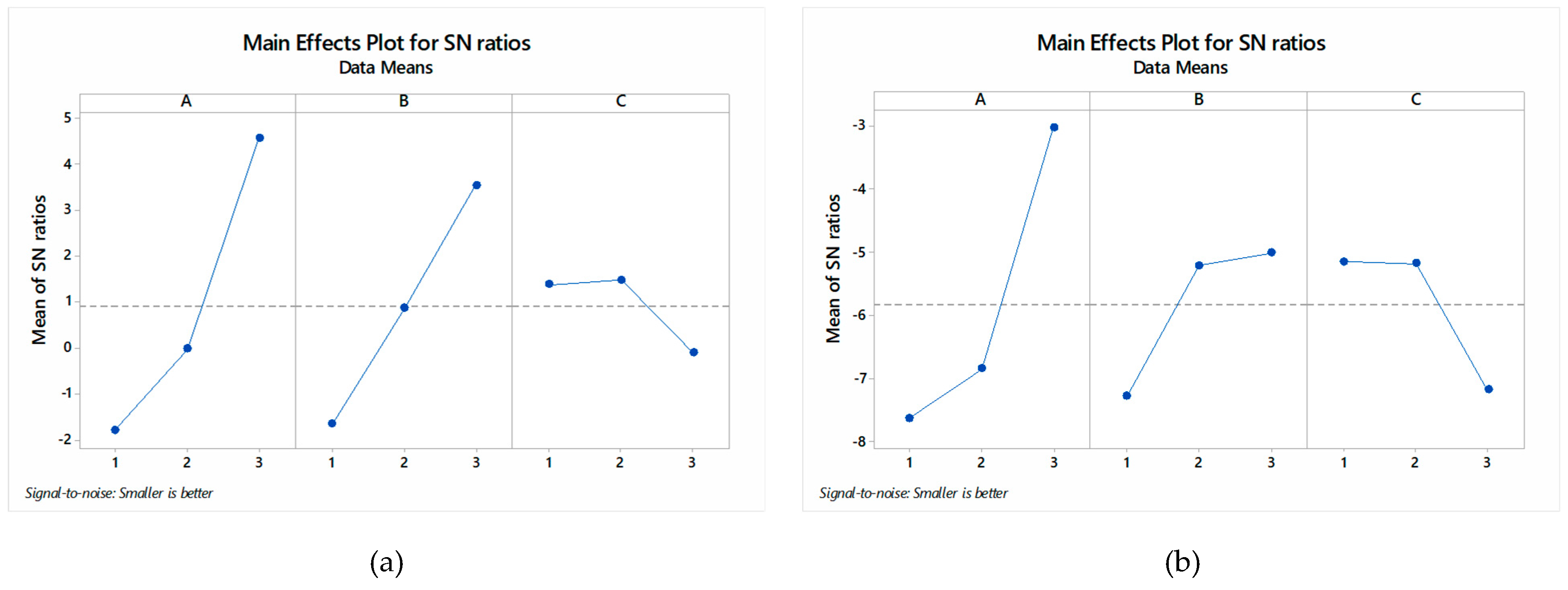
| Level | F | V | DoC |
|---|---|---|---|
| DIW | |||
| 1 | −1.79662 | −1.66336 | 1.35969 |
| 2 | −0.03060 | 0.84546 | 1.46335 * |
| 3 | 4.53868 * | 3.52936 * | −0.11158 |
| Delta | 6.33530 | 5.19272 | 1.57493 |
| Rank | 1 | 2 | 3 |
| DIH | |||
| 1 | −7.624 | −7.280 | −5.153 * |
| 2 | −6.849 | −5.212 | −5.175 |
| 3 | −3.029 * | −5.011 * | −7.175 |
| Delta | 4.595 | 2.269 | 2.022 |
| Rank | 1 | 2 | 3 |
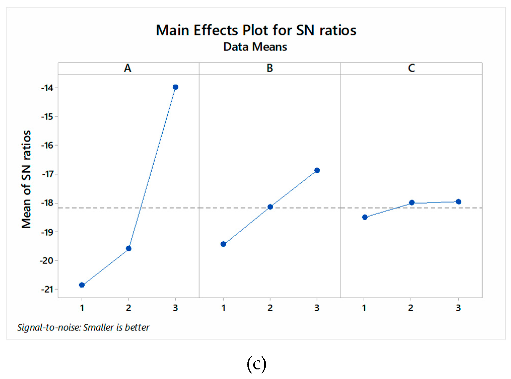
| Ra | |||
| 1 | −20.87 | −16.87 * | −17.92 |
| 2 | −19.61 | −18.13 | −17.86 * |
| 3 | −13.97 * | −19.46 | −18.68 |
| Delta | 6.91 | 2.59 | 0.82 |
| Rank | 1 | 2 | 3 |
| Output Response | Predicted | Experimental | Deviation (±) |
|---|---|---|---|
| DIW (mm) | 0.410 | 0.415 | 0.05 |
| DIH (mm) | 1.018 | 1.107 | 0.089 |
| Ra (µm) | 4.16 | 4.11 | 0.05 |
© 2020 by the authors. Licensee MDPI, Basel, Switzerland. This article is an open access article distributed under the terms and conditions of the Creative Commons Attribution (CC BY) license (http://creativecommons.org/licenses/by/4.0/).
Share and Cite
Sandhu, K.; Singh, G.; Singh, S.; Kumar, R.; Prakash, C.; Ramakrishna, S.; Królczyk, G.; Pruncu, C.I. Surface Characteristics of Machined Polystyrene with 3D Printed Thermoplastic Tool. Materials 2020, 13, 2729. https://doi.org/10.3390/ma13122729
Sandhu K, Singh G, Singh S, Kumar R, Prakash C, Ramakrishna S, Królczyk G, Pruncu CI. Surface Characteristics of Machined Polystyrene with 3D Printed Thermoplastic Tool. Materials. 2020; 13(12):2729. https://doi.org/10.3390/ma13122729
Chicago/Turabian StyleSandhu, Kamalpreet, Gurminder Singh, Sunpreet Singh, Raman Kumar, Chander Prakash, Seeram Ramakrishna, Grzegorz Królczyk, and Catalin I. Pruncu. 2020. "Surface Characteristics of Machined Polystyrene with 3D Printed Thermoplastic Tool" Materials 13, no. 12: 2729. https://doi.org/10.3390/ma13122729