
Engineered Magnetization Dynamics of Magnonic Nanograting Filters


1
Department of Electrical and Electronics Engineering, Koç University, Sarıyer, 34450 Istanbul, Turkey
2
Department of Physics, Massachusetts Institute of Technology, Cambridge, MA 02139, USA
*
Author to whom correspondence should be addressed.
Magnetochemistry 2021, 7(6), 81; https://doi.org/10.3390/magnetochemistry7060081
Submission received: 10 April 2021
/
Revised: 7 May 2021
/
Accepted: 14 May 2021
/
Published: 3 June 2021
(This article belongs to the Special Issue Micromagnetics and Magnetization Processes in Nanomagnetism)
Abstract
:Magnonic crystals and gratings could enable tunable spin-wave filters, logic, and frequency multiplier devices. Using micromagnetic models, we investigate the effect of nanowire damping, excitation frequency and geometry on the spin wave modes, spatial and temporal transmission profiles for a finite patterned nanograting under external direct current (DC) and radio frequency (RF) magnetic fields. Studying the effect of Gilbert damping constant on the temporal and spectral responses shows that low-damping leads to longer mode propagation lengths due to low-loss and high-frequency excitations are also transmitted with high intensity. When the nanowire is excited with stronger external RF fields, higher frequency spin wave modes are transmitted with higher intensities. Changing the nanowire grating width, pitch and its number of periods helps shift the transmitted frequencies over super high-frequency (SHF) range, spans S, C, X, Ku, and K bands (3–30 GHz). Our design could enable spin-wave frequency multipliers, selective filtering, excitation, and suppression in magnetic nanowires.
1. Introduction
Spin signal processing such as filtering, frequency multiplication, and excitation in GHz bands could enable on-chip integration for compact microwave data communication, data storage, as well as information transfer in ferromagnetic waveguides [1,2]. Many of these functionalities could be established within the same physically defined structure via magnonic crystals (MCs) on the nanoscale. MC are spin waveguides that can be rationally designed [3] or dynamically reconfigured [4] for functional spin transfer by engineering the voltage or magnetic field induced spin-wave dispersion dynamics. Spin-wave eigenmodes in magnetic nanomaterials are the outcomes of spin-wave dispersion effects originating from the total effective magnetic field arising from an exchange, geometry related, anisotropy, and external excitation terms [5,6]. Several methods have been implemented to produce the desired spin transmission spectra. Realizing a geometry-driven energy band gap formation allows enabling several prominent features to emerge, such as guided information carrier by periodic arrays of nanostrips [7,8] and width–modulated nanogratings [9,10,11,12]. Besides that spatial periodic variation of saturation magnetization, alternating nanostrips, filters, and phase shifters were investigated with different material classes [8,13,14,15,16], where Y3Fe5O12 (YIG) and permalloy were the common types for MC. YIG provides lower damping and low loss propagation of spin-waves [1,17]. Permalloy is an optically reflective magnetic metal with higher saturation magnetic moment which makes this material useful for Kerr and Brillouin light scattering microscopy [9,10,12,18]. Magnonic crystals could provide spin-wave band-pass [19] or band-reject [12,17] spectral filtering through their magnon band gaps. MC width variation leads to the modulation of the spin-wave wavevectors, and consequently to the formation of frequency rejection bands in the spin-wave transmission characteristics. Further analysis of the temporal effects of such nanograting wires is needed in order to understand the contribution of material parameters such as Gilbert damping on the spin-wave dynamics evolution and the spin-wave mode propagation. In addition, geometry parameters are important to consider in terms of their contribution to the time and frequency profiles of the spin-wave dynamics and transmission behavior in MC. Steady state transmission spectrum should also be analyzed in terms of the excitation conditions which are concerned with RF signal frequencies and the bias field conditions.
Here, we model the temporal and spatial magnetization dynamics in nanogratings. The spectrum of spin waves propagating in the MC filter is important to understand the effect of modulation on the overall spectral transmission. Material- and geometry-related parameters concerned with the structure presented here, are worth investigating to evaluate its performance as a nanograting filter. We look at the effect of increasing the excitation frequency of an RF signal applied to the nanowire, which contributes to the excitation of the eigenmode in the structure.
2. Materials and Methods
In this work, Object-Oriented Micromagnetic Framework (OOMMF) simulations were performed on the filter structure shown in Figure 1a. OOMMF solves Landau-Lifshitz-Gilbert (LLG) equation using finite-difference methods [20,21,22,23].
where, m is the normalized magnetization vector, γ is the gyromagnetic ratio, α is the Gilbert damping constant. Equation (1) is comprised of two terms: the first term describes the magnetization precession under the presence of an effective magnetic field (Heff) and the second term captures the Gilbert damping effect. The damping term helps reach the minimum energy state by forcing the magnetization to orient itself parallel to the effective field [24]. Heff can be written as the sum of the terms: the exchange field (Hex), demagnetization fields (Hdemag), uniaxial magneto-crystalline anisotropy (Huniaxial) as well as DC and RF external magnetic field terms (HDC, HRF) as in Equation (2). Hdemag is the demagnetizing field, which provides a major contribution, resulting from shape anisotropy [25].
∂m/∂t = -γm × Heff + αm × ∂m/∂t
Heff = Hex + Hdemag + Huniaxial + HDC + HRF
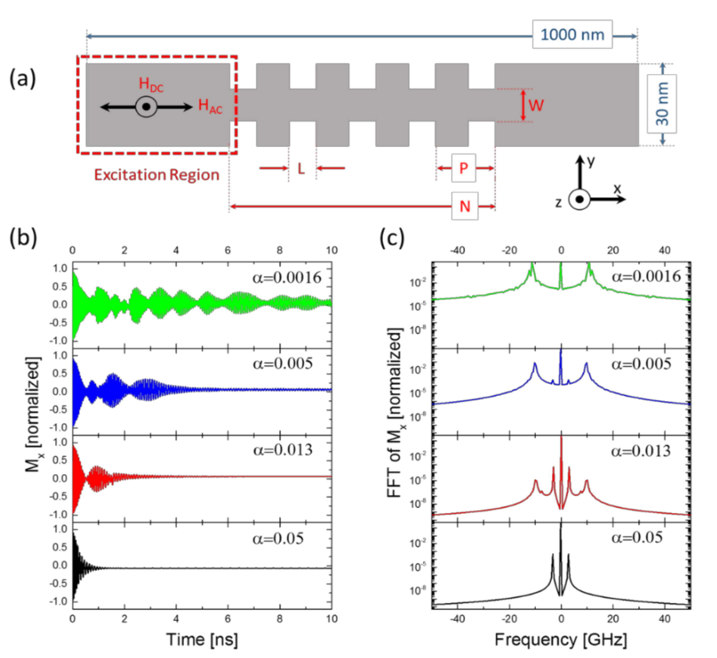
Here, three main geometric parameters of the nanograting object were investigated in our study by aligning the demagnetizing field along the long axis and in-plane, where the long axis of the nanowire was parallel to the horizontal plane. The micromagnetic simulations have been run under a finite mesh size of 5 × 5 × 10 nm3 with a simulation time step of 2 ps [26], which is sufficient to run the simulation with parametric sweeps. The geometry under test is depicted in Figure 1a: an excitation region of 500 nm length, and this region followed by a finite periodic structure with a grating region in the middle of the nanowire. The total length of the structure has been kept at 1000 nm and the thickness is set to 10 nm. The grating region includes the periodic features with period count N, periodicity P, grating spacing W, and trench width L as shown in the figure. For further analysis, the effects of geometric dimensions (W, P, N), Gilbert damping parameter, and the RF excitation frequency on the nanowire filter’s magnetization dynamics and its spectral magnetization output were modelled to observe the mode transition behavior in detail.
To observe the spin-wave propagation and magnetization dynamics through the nanograting filter geometry, a 1000 mT external DC magnetic field is applied on the wire along the z-axis. Along with this field, the nanowire is also excited by a 3 GHz, 500 mT amplitude continuous RF sinusoidal external magnetic field in the +x-direction of the red dashed rectangular region. This configuration leads to Forward Volume Spin Waves (FVSWs), which propagate in the magnetized media with an in-plane propagation wave vector [27,28]. After applying the DC and RF external magnetic fields, spins will precess and eventually settle along the z-direction again due to damping. Material parameters used in the simulations are saturation magnetization Ms = 840 × 103 A m−1 and the exchange constant (Aex) is 13 × 10−12 J m−1. The uniaxial anisotropy constant K1 is 100 J m−3 set along the +z-axis, while Gilbert damping constant α = 0.013. In this study, the small uniaxial magnetic anisotropy effect Ku was added to the simulation since it can be present in magnetic materials used in thin film MC. Earlier experimental studies showed that in thin YIG films, perpendicular magnetic anisotropy could arise due to lattice strain [29] and in permalloy, growth-induced anisotropy emerges due to off stoichiometry [30].
These material constants are close to Permalloy’s parameters. Permalloy’s intrinsic Gilbert damping and uniaxial anisotropy constant Ku could vary due to surface strain, stoichiometric variations and growth-induced effects. Thus, the change of the spectral and temporal characteristics are investigated for permalloy-like materials.
While investigating the effect of geometry, each parameter is varied in discrete steps while keeping the others fixed. For investigating the effect of damping and RF excitation field frequencies, the geometry has been fixed with N = 5, W = 24 nm, L = 10 nm, and P = 20 nm. For investigating the effect of N, the geometry and excitation conditions are fixed with W = 24 nm, L = 10 nm, P = 20 nm, α = 0.013 and f = 3 GHz. For investigating the effect of P, the geometry and excitation conditions are fixed with W = 24 nm, L = 10 nm, α = 0.013 and f = 3 GHz. The remaining section on the right contains the grating and is also 500 nm fixed in total length. We swept P and N parameters and obtained the spectra and the temporal results accordingly. The grating region changes in length according to the changes in the period length P or the period count N. In all cases, the overall length of the right region is fixed at 500 nm so that the total length of the structure is fixed at 1000 nm. The average magnetization dynamics of the spin-wave components of the overall structure were calculated in the time domain and Fourier transform was applied on the time domain transmission dynamics to obtain the individual spin-wave spectra.
3. Results and Discussion
We include the results of varying material properties; Gilbert damping coefficient (α) and Ms, varying RF signal excitation frequency and the change in the width modulated grating geometry, on the output magnetization temporal profiles and their steady-state spectra of the nanowire filter.
3.1. Effect of Damping, and Ms on Mx and Mz Transient and Steady State Responses
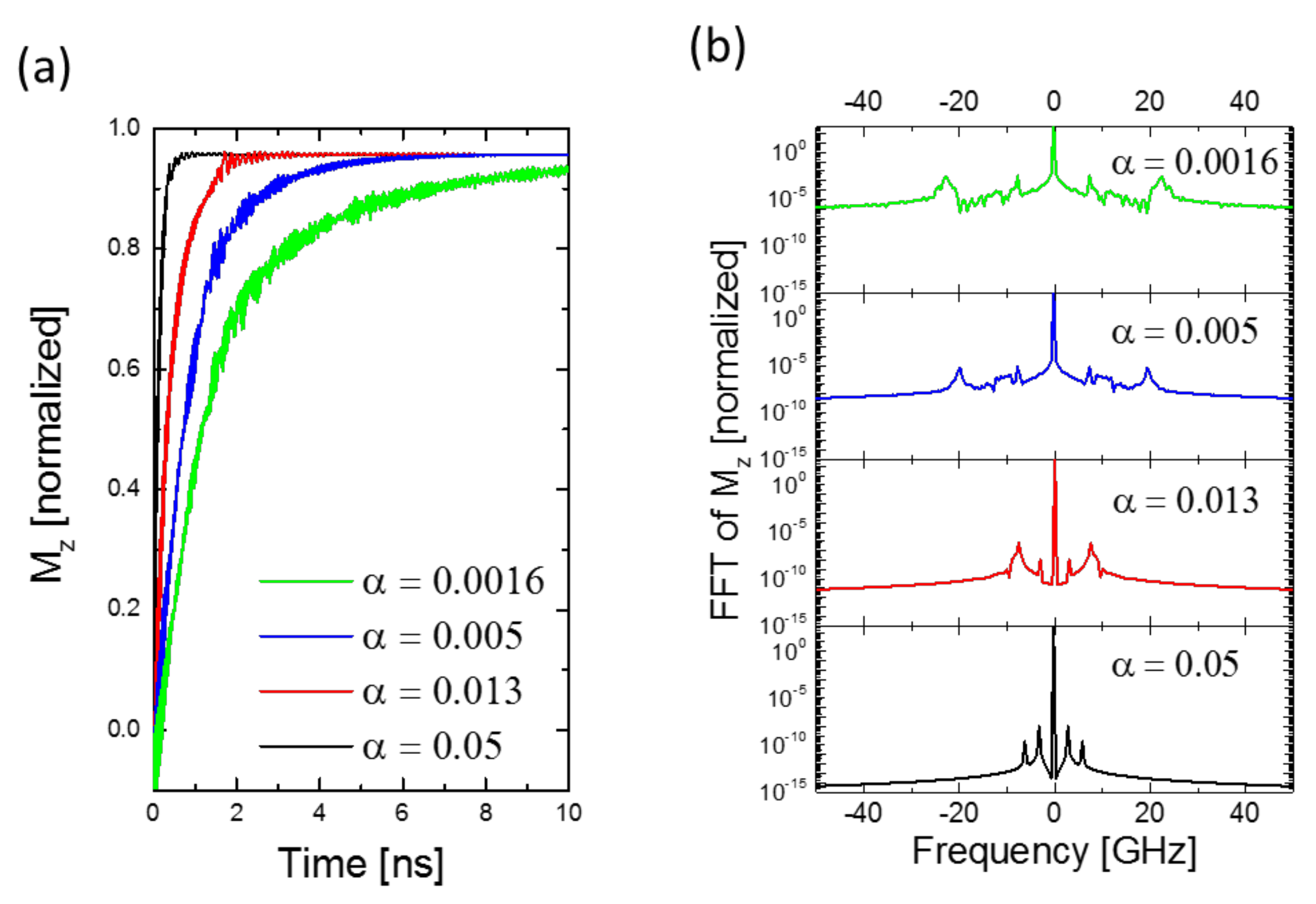
The effect of damping on both transient and steady-state responses of the magnetization in the nanograting structure are shown, respectively, in Figure 1b and Figure 2b. Small damping values allow for longer and higher-frequency oscillations in Mx time profile (see Figure 2a). This is also shown in Mz time response, which causes a lower slope for lower damping values. So higher Gilbert damping reduces the energy required to shift to steady-state and for spins to transport such energy. To translate this effect into the frequency domain, Figure 1c and Figure 2b show the resulting excited frequency peaks of filter nanowire modes. Mx peak intensities are reduced for higher damping and the overall spectral magnitude is lower. Increasing Gilbert damping re-shifts the frequencies of the excited modes, so the higher frequency mode peaks are shifted toward lower frequency magnitudes while the 3 GHz peak remains unchanged even in magnitude.
3.2. Effect of Frequency of RF Signal on Mx and Mz Steady State Responses
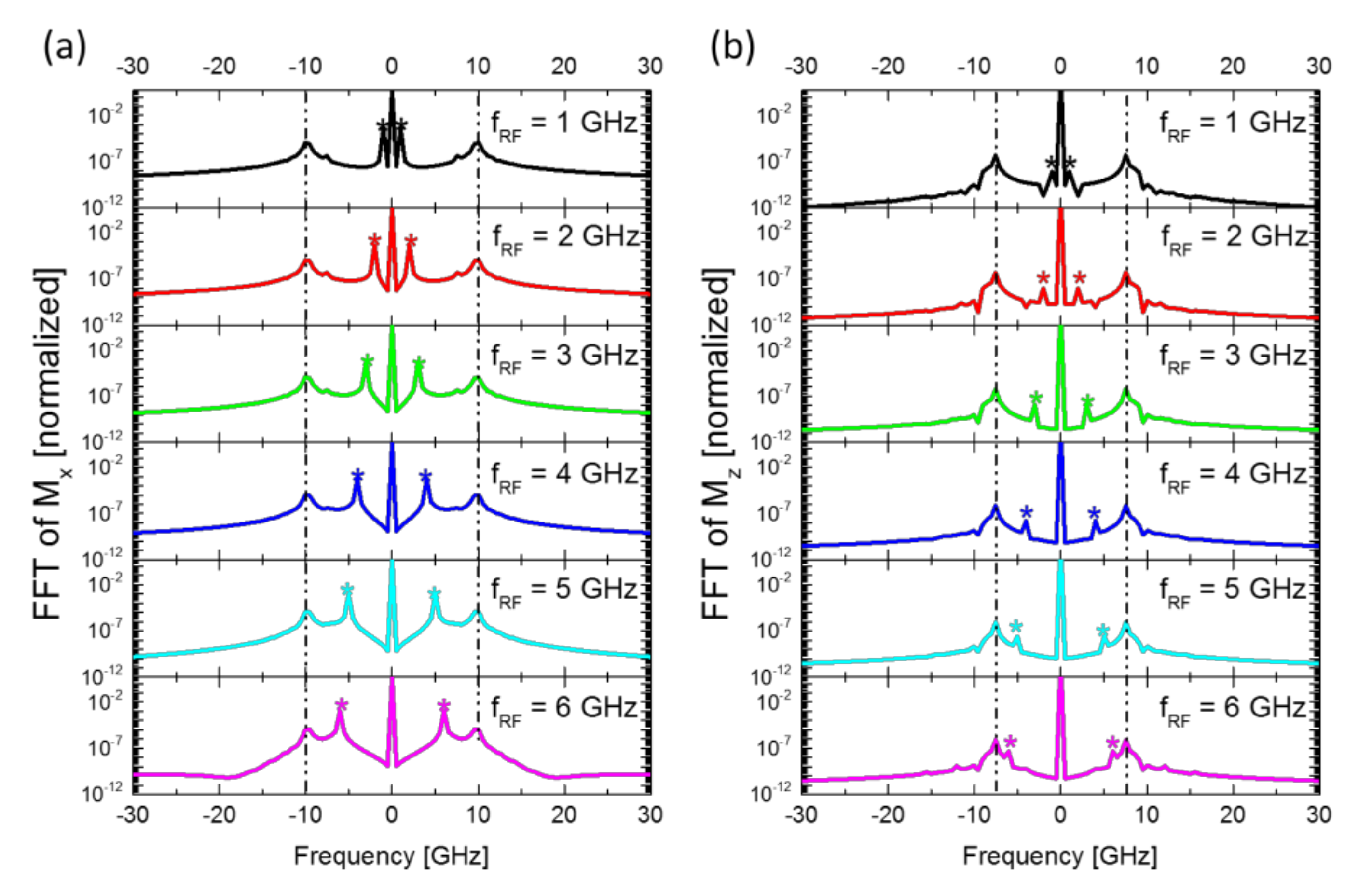
The RF excitation signal which is applied along the longitudinal axis of the nanowire has a significant contribution to the spectral features and modes of the nanograting filter response, as shown in Figure 3. The Mx spectra in Figure 3a show the different excitation frequency peaks of the RF signal along the longitudinal direction. The first neighbors around the zero-bias peak signed with star labels are an indication of the excitation frequency. A higher frequency excited peak (at around 10 GHz) at each spectrum curve appears unaffected by the increasing excitation frequency, which may imply that the magnetization response along this magnetization component does not affect higher frequency modes resulting from spin-wave generation in the nanowire. In Figure 3b of the Mz spectra, the excited modes’ intensities also experience an increase with the higher frequencies of the excitation signal, while a 7.5 GHz excited peak appearing for the same nanowire geometry and material settings is clearly unaffected by this change. This shows a possible frequency-selective property of the nanowire structure prone to any change in an applied RF signal frequency.
3.3. Effect of Nanograting Structure Geometry on Mx and Mz Responses
This section is concerned with discussing the resulting changes in the width-modulated central structure on the average magnetization dynamics of the overall nanowire. Each parameter is evaluated while keeping the rest of the geometry and the material properties unchanged.
3.3.1. Periodicity (N) and Period Length (P)
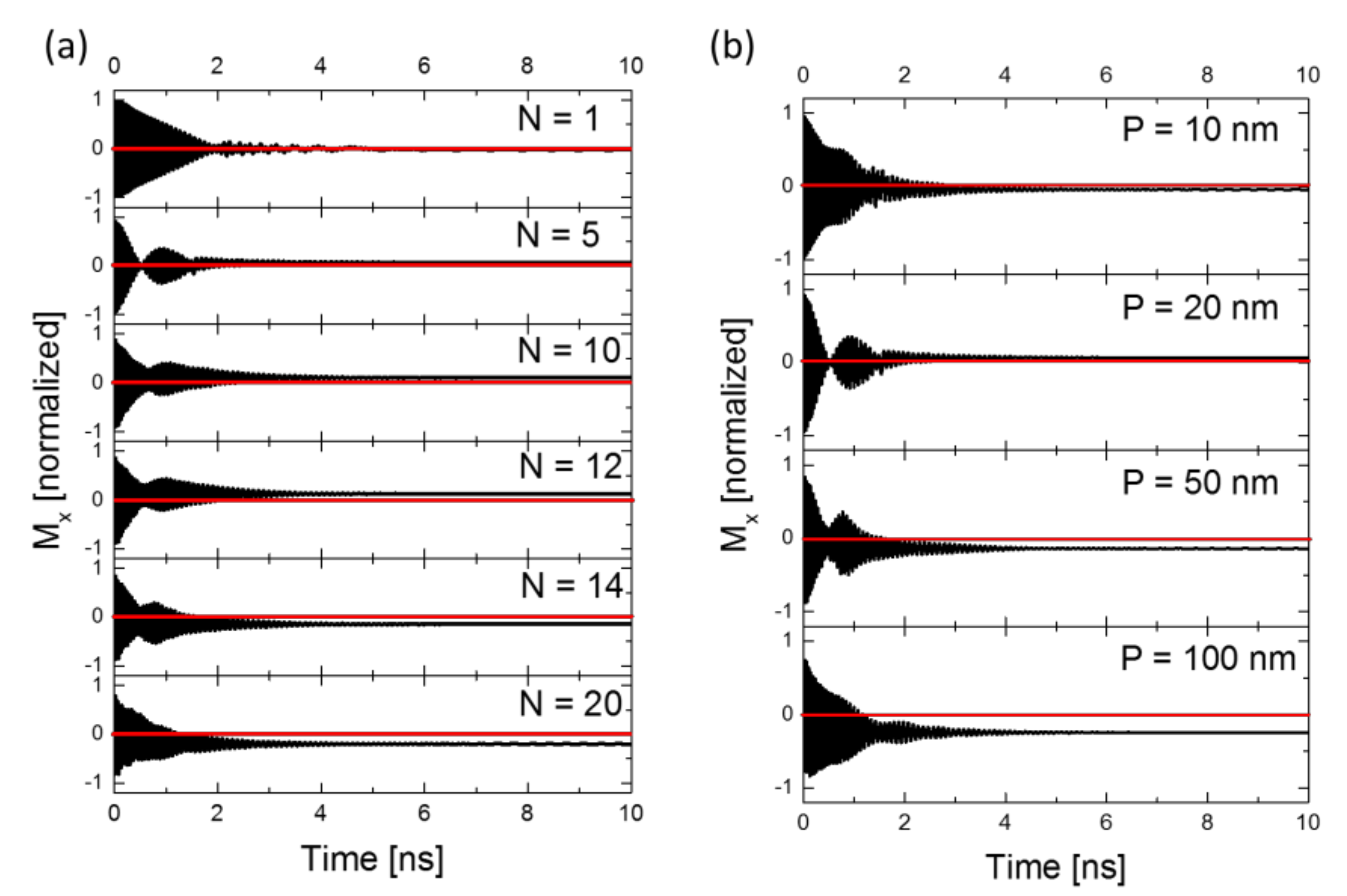
Figure 4 demonstrates the changes in the magnetization (Mx) orientation over the nanowire from increasing both N and P. Wherefrom Figure 4a for N > 12, the average magnetization flips to the negative direction of the x-axis and becomes more negative as N increases. This change is a result of the increase in the contribution of the demagnetization field to the overall effective field across the structure as N becomes larger. The same can be concluded from Figure 4b, as P forces a change in the overall Mx due to the demagnetizing field, causing it to be more negative as P goes beyond 50 nm. The non-zero magnetization in steady state for both plots of N and P indicates that not all the magnetic moments are oriented in the same direction. Some portion of the moment along the z-direction causes a shifting of the overall signal from the equilibrium [31].
3.3.2. Filter Response for W (nm)
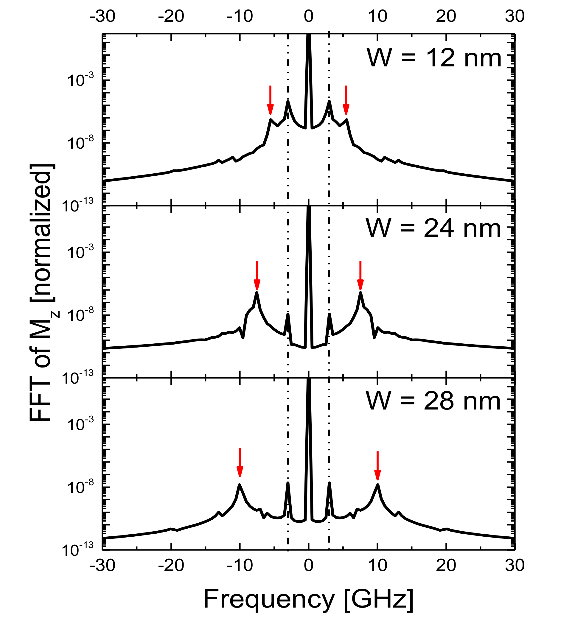
Another way to relate the output spectrum of the nanowire to the selectively produced mode is to cause W to become narrower or wider, within the given structure width. This is demonstrated in Figure 5, where spectral peaks are shifted to higher frequencies as W increases. Since the MC is excited at DC (0 Hz) and 3 GHz, these driving forces appear as steady-state peaks in all spectra. The major peaks other than 0 Hz and 3 GHz are attributed to the demagnetizing field-driven effects. Figure 5 shows that increasing the width W from 12 to 28 nm shifts the high frequency peak from 5 to 10 GHz.
4. Conclusions
In this paper, the magnetization dynamics for nanowires are modelled by systematically varying Gilbert damping constants, nanowire geometric parameters, and RF excitation frequency to elucidate their effects on the spin-wave modes and their temporal behavior. Gilbert damping causes the overall magnetization vectors to decay faster in time and their energy spectra are reduced. Spectral peaks tend to shift toward lower frequencies as the structure is subjected to higher damping. This property constitutes the selective frequency response as a filter. It is also observed that increasing the excitation frequency of the RF signal in the longitudinal axis affects the magnitude of the resulting spectrum while keeping certain excited mode peaks unaffected along x and z components. Variation in the geometry of the width modulation section of the structure plays a role in defining the amount of contribution of the demagnetizing field along the nanowire by changing the N and P values. The spectrum peaks shift to higher frequencies as W increases.
Previous studies on similar but bulk-like micron-thick structures [14] showed reflection-less magnon dynamics and tunable band structures. From a practical standpoint, a reflection-less magnonic crystal could be the building block needed for eliminating the back-coupling between the cascaded magnon devices such as filters, logic gates, MC-based frequency multiplexers and demultiplexers. A detailed investigation of the material property, external field and geometry dependence of this structure with this study could shed light on magnon dynamics and spectral characteristics in thin film MC. Thus, this study could pave the way to more advanced cascaded magnon logic structures.
Author Contributions
R.Y. did the modelling and simulations, F.K. and M.C.O. designed and supervised the study. All authors wrote and commented on the manuscript. All authors have read and agreed to the published version of the manuscript.
Funding
This research was funded by Turkish Academy of Science TÜBA-GEBİP Award (2019), The Scientific and Technological Research Council of Turkey, grant number 120F230 and by European Research Council (ERC) grant number 948063. The APC was funded by TÜBA-GEBİP and the ERC grants.
Data Availability Statement
The data presented in this study are available on request from the corresponding author. The data are not publicly available due to ongoing unpublished research.
Acknowledgments
Funding from TÜBA-GEBİP Award by Turkish Academy of Sciences, TUBITAK grant no. 120F230 and European Research Council project SKYNOLIMIT no. 948063 are gratefully acknowledged.
Conflicts of Interest
The authors declare no conflict of interest.
References
- Chumak, A.V.; Serga, A.A.; Hillebrands, B.; Kostylev, M.P. Scattering of backward spin waves in a one-dimensional magnonic crystal. Appl. Phys. Lett. 2008, 93, 022508. [Google Scholar] [CrossRef] [Green Version]
- Deng, J.; Zhu, M.; Luo, J.; Zheng, H.; Zheng, P.; Feng, C.; Luo, J. Modulation of magnonic bands of dipole-exchange spin waves in fishbone-like yttrium iron garnet nanostrip magnonic crystal waveguides. J. Phys. D Appl. Phys. 2020, 53, 315001. [Google Scholar] [CrossRef]
- Sheshukova, S.E.; Beginin, E.N.; Sadovnikov, A.V.; Sharaevsky, Y.P.; Nikitov, S.A. Multimode propagation of magnetostatic waves in a width-modulated yttrium-iron-garnet waveguide. IEEE Magn. Lett. 2014, 5, 1–4. [Google Scholar] [CrossRef]
- Haldar, A.; Kumar, D.; Adeyeye, A.O. A reconfigurable waveguide for energy-efficient transmission and local manipulation of information in a nanomagnetic device. Nat. Nanotechnol. 2016, 11, 437–443. [Google Scholar] [CrossRef]
- Lisenkov, I.; Kalyabin, D.; Osokin, S.; Klos, J.W.; Krawczyk, M.; Nikitov, S. Nonreciprocity of edge modes in 1D magnonic crystal. J. Magn. Magn. Mater. 2015, 378, 313–319. [Google Scholar] [CrossRef]
- Ustinov, A.B.; Drozdovskii, A.V.; Kalinikos, B.A. Multifunctional nonlinear magnonic devices for microwave signal processing. Appl. Phys. Lett. 2010, 96, 142513. [Google Scholar] [CrossRef]
- Gubbiotti, G.; Zhou, X.; Haghshenasfard, Z.; Cottam, M.G.; Adeyeye, A.O.; Kostylev, M. Interplay between intra- and inter-nanowires dynamic dipolar interactions in the spin wave band structure of Py/Cu/Py nanowires. Sci. Rep. 2019, 9. [Google Scholar] [CrossRef] [PubMed]
- Wang, Z.K.; Zhang, V.L.; Lim, H.S.; Ng, S.C.; Kuok, M.H.; Jain, S.; Adeyeye, A.O. Observation of frequency band gaps in a one-dimensional nanostructured magnonic crystal. Appl. Phys. Lett. 2009, 94, 083112. [Google Scholar] [CrossRef] [Green Version]
- Ciubotaru, F.; Chumak, A.V.; Grigoryeva, N.Y.; Serga, A.A.; Hillebrands, B. Magnonic band gap design by the edge modulation of micro-sized waveguides. J. Phys. D Appl. Phys. 2012, 45, 255002. [Google Scholar] [CrossRef] [Green Version]
- Kim, S.-K.; Lee, K.-S.; Han, D.-S. A gigahertz-range spin-wave filter composed of width-modulated nanostrip magnonic-crystal waveguides. Appl. Phys. Lett. 2009, 95, 082507. [Google Scholar] [CrossRef] [Green Version]
- Lee, K.-S.; Han, D.-S.; Kim, S.-K. Physical origin and generic control of magnonic band gaps of dipole-exchange spin waves in width-modulated nanostrip waveguides. Phys. Rev. Lett. 2009, 102, 127202. [Google Scholar] [CrossRef] [Green Version]
- Wang, Q.; Zhong, Z.; Jin, L.; Tang, X.; Bai, F.; Zhang, H.; Beach, G.S.D. Design of nanostrip magnonic crystal waveguides with a single magnonic band gap. J. Magn. Magn. Mater. 2013, 340, 23–26. [Google Scholar] [CrossRef]
- Ciubotaru, F.; Chumak, A.V.; Obry, B.; Serga, A.A.; Hillebrands, B. Magnonic band gaps in waveguides with a periodic variation of the saturation magnetization. Phys. Rev. B 2013, 88, 134406. [Google Scholar] [CrossRef] [Green Version]
- Frey, P.; Nikitin, A.A.; Bozhko, D.A.; Bunyaev, S.A.; Kakazei, G.N.; Ustinov, A.B.; Kalinikos, B.A.; Ciubotaru, F.; Chumak, A.V.; Wang, Q.; et al. Reflection-less width-modulated magnonic crystal. Commun. Phys. 2020, 3, 1–7. [Google Scholar] [CrossRef]
- Goto, T.; Shimada, K.; Nakamura, Y.; Uchida, H.; Inoue, M. One-dimensional magnonic crystal with Cu stripes for forward volume spin waves. Phys. Rev. Appl. 2019, 11, 014033. [Google Scholar] [CrossRef] [Green Version]
- Ma, F.; Lim, H.; Zhang, V.; Ng, S.; Kuok, M. Magnonic band structure investigation of one-dimensional bi-component magnonic crystal waveguides. Nanoscale Res. Lett. 2012, 7, 498. [Google Scholar] [CrossRef] [Green Version]
- Lutsev, L.V.; Dubovoy, V.A.; Stognij, A.I.; Novitskii, N.N.; Mozharov, A.M.; Mukhin, I.S.; Ketsko, V.A. Spin-wave filters based on thin Y3Fe5O12 films on Gd3Ga5O12 and Si substrates for microwave applications. J. Appl. Phys. 2020, 127, 183903. [Google Scholar] [CrossRef]
- Fallarino, L.; Madami, M.; Duerr, G.; Grundler, D.; Gubbiotti, G.; Tacchi, S.; Carlotti, G. Propagation of spin waves excited in a permalloy film by a finite-ground coplanar waveguide: A combined phase-sensitive micro-focused brillouin light scattering and micromagnetic study. IEEE Trans. Magn. 2013, 49, 1033–1036. [Google Scholar] [CrossRef]
- Mohseni, M.; Wang, Q.; Heinz, B.; Kewenig, M.; Schneider, M.; Kohl, F.; Lägel, B.; Dubs, C.; Chumak, A.V.; Pirro, P. Controlling the nonlinear relaxation of quantized propagating magnons in nanodevices. Phys. Rev. Lett. 2021, 126. [Google Scholar] [CrossRef]
- Carter, R.L.; Owens, J.M.; Smith, C.V.; Reed, K.W. Ion-implanted magnetostatic wave reflective array filters. J. Appl. Phys. 1982, 53, 2655–2657. [Google Scholar] [CrossRef]
- Divinskiy, B.; Urazhdin, S.; Demokritov, S.O.; Demidov, V.E. Controlled nonlinear magnetic damping in spin-Hall nano-devices. Nat. Commun. 2019, 10, 1–7. [Google Scholar] [CrossRef]
- Kim, Y.M.; Han, S.H.; Kim, H.J.; Choi, D.; Kim, K.H.; Kim, J. Thickness effects on magnetic properties and ferromagnetic resonance in Co–Ni–Fe–N soft magnetic thin films. J. Appl. Phys. 2002, 91, 8462. [Google Scholar] [CrossRef]
- Richardson, D.; Kalinikos, B.A.; Carr, L.D.; Wu, M. Spontaneous exact spin-wave fractals in magnonic crystals. Phys. Rev. Lett. 2018, 121, 107204. [Google Scholar] [CrossRef] [PubMed] [Green Version]
- Lakshmanan, M. The fascinating world of the Landau–Lifshitz–Gilbert equation: An overview. Philos. Trans. R. Soc. A Math. Phys. Eng. Sci. 2011, 369, 1280–1300. [Google Scholar] [CrossRef] [PubMed]
- Kruglyak, V.V.; Hicken, R.J. Magnonics: Experiment to prove the concept. J. Magn. Magn. Mater. 2006, 306, 191–194. [Google Scholar] [CrossRef] [Green Version]
- Duflou, R.; Ciubotaru, F.; Vaysset, A.; Heyns, M.; Sorée, B.; Radu, I.P.; Adelmann, C. Micromagnetic simulations of magnetoelastic spin wave excitation in scaled magnetic waveguides. Appl. Phys. Lett. 2017, 111, 192411. [Google Scholar] [CrossRef] [Green Version]
- Klingler, S.; Pirro, P.; Brächer, T.; Leven, B.; Hillebrands, B.; Chumak, A.V. Spin-wave logic devices based on isotropic forward volume magnetostatic waves. Appl. Phys. Lett. 2015, 106, 212406. [Google Scholar] [CrossRef] [Green Version]
- Prabhakar, A.; Stancil, D. Propagation Characteristics and Excitation of Dipolar Spin Waves. In Spin Waves-Theory and Applications; Springer: Berlin, Germany, 2009; p. 169. [Google Scholar]
- Ding, J.; Liu, C.; Zhang, Y.; Erugu, U.; Quan, Z.; Yu, R.; McCollum, E.; Mo, S.; Yang, S.; Ding, H.; et al. Nanometer-thick yttrium iron garnet films with perpendicular anisotropy and low damping. Phys. Rev. Appl. 2020, 14, 014017. [Google Scholar] [CrossRef]
- Fujii, T.; Uchiyama, S.; Masuda, M.; Sakaki, Y. On the origin of uniaxial anisotropy in permalloy thin films. IEEE Trans. Magn. 1968, 4, 515–519. [Google Scholar] [CrossRef]
- Labrune, M.; Miltat, J. Wall structures in ferro/antiferromagnetic exchange-coupled bilayers: A numerical micromagnetic approach. J. Magn. Magn. Mater. 1995, 151, 231–245. [Google Scholar] [CrossRef]
Figure 1.
Filter geometry applied external RF and DC magnetic field regions and transmission along with x-axis magnetization. (a) The simulated nanowire geometry with the orientations of external RF and DC magnetic field (respectively, HAC and HDC) excitations (dimensions not to scale). The effect of increasing Gilbert damping coefficient on transient Mx in (b) time and (c) frequency (for 8–10 ns time window) domains (the rest of the parameters were held fixed).

Figure 2.
Damping coefficient dependence of z-axis transmission, where 3 GHz RF signal is used for the excitations. The effect of increasing Gilbert damping coefficient on transient Mz in (a) time and (b) frequency (for 8–10 ns time window) domains (the rest of the parameters were fixed). The nanogratings with lower damping coefficients transmit higher-frequency oscillations with higher transmission ratios.

Figure 3.
Effects of external RF magnetic field excitation. The effect of increasing excitation frequency of RF signal on (a) Mx and (b) Mz spectral peaks’ intensities and positions/frequencies, for 8–10 ns time window. The damping coefficient is kept at the value of 0.013 for all cases.
Figure 3.
Effects of external RF magnetic field excitation. The effect of increasing excitation frequency of RF signal on (a) Mx and (b) Mz spectral peaks’ intensities and positions/frequencies, for 8–10 ns time window. The damping coefficient is kept at the value of 0.013 for all cases.

Figure 4.
The effect of increasing the (a) periodicity N and (b) period P of the nanograting structure on Mx temporal plots. Other geometry parameters are fixed. Material parameters; α = 0.013 and Ms = 840 × 103 A m−1. Excitation frequency is 3 GHz with 500 mT RF and 1000 mT DC bias field.
Figure 4.
The effect of increasing the (a) periodicity N and (b) period P of the nanograting structure on Mx temporal plots. Other geometry parameters are fixed. Material parameters; α = 0.013 and Ms = 840 × 103 A m−1. Excitation frequency is 3 GHz with 500 mT RF and 1000 mT DC bias field.

Figure 5.
Mz spectra resulting from changing W (nm), for 8–10 ns time window. Dashed lines are an indication of the excitation frequency for three cases.
Figure 5.
Mz spectra resulting from changing W (nm), for 8–10 ns time window. Dashed lines are an indication of the excitation frequency for three cases.

Publisher’s Note: MDPI stays neutral with regard to jurisdictional claims in published maps and institutional affiliations. |
© 2021 by the authors. Licensee MDPI, Basel, Switzerland. This article is an open access article distributed under the terms and conditions of the Creative Commons Attribution (CC BY) license (https://creativecommons.org/licenses/by/4.0/).
Share and Cite
MDPI and ACS Style
Yagan, R.; Katmis, F.; Onbaşlı, M.C. Engineered Magnetization Dynamics of Magnonic Nanograting Filters. Magnetochemistry 2021, 7, 81. https://doi.org/10.3390/magnetochemistry7060081
AMA Style
Yagan R, Katmis F, Onbaşlı MC. Engineered Magnetization Dynamics of Magnonic Nanograting Filters. Magnetochemistry. 2021; 7(6):81. https://doi.org/10.3390/magnetochemistry7060081
Chicago/Turabian StyleYagan, Rawana, Ferhat Katmis, and Mehmet C. Onbaşlı. 2021. "Engineered Magnetization Dynamics of Magnonic Nanograting Filters" Magnetochemistry 7, no. 6: 81. https://doi.org/10.3390/magnetochemistry7060081
Note that from the first issue of 2016, this journal uses article numbers instead of page numbers. See further details here.