
Investigation of the Effect of Spin Crossover on the Static and Dynamic Properties of MEMS Microcantilevers Coated with Nanocomposite Films of [Fe(Htrz)2(trz)](BF4)@P(VDF-TrFE)

 , ,
, , 
Abstract
:1. Introduction
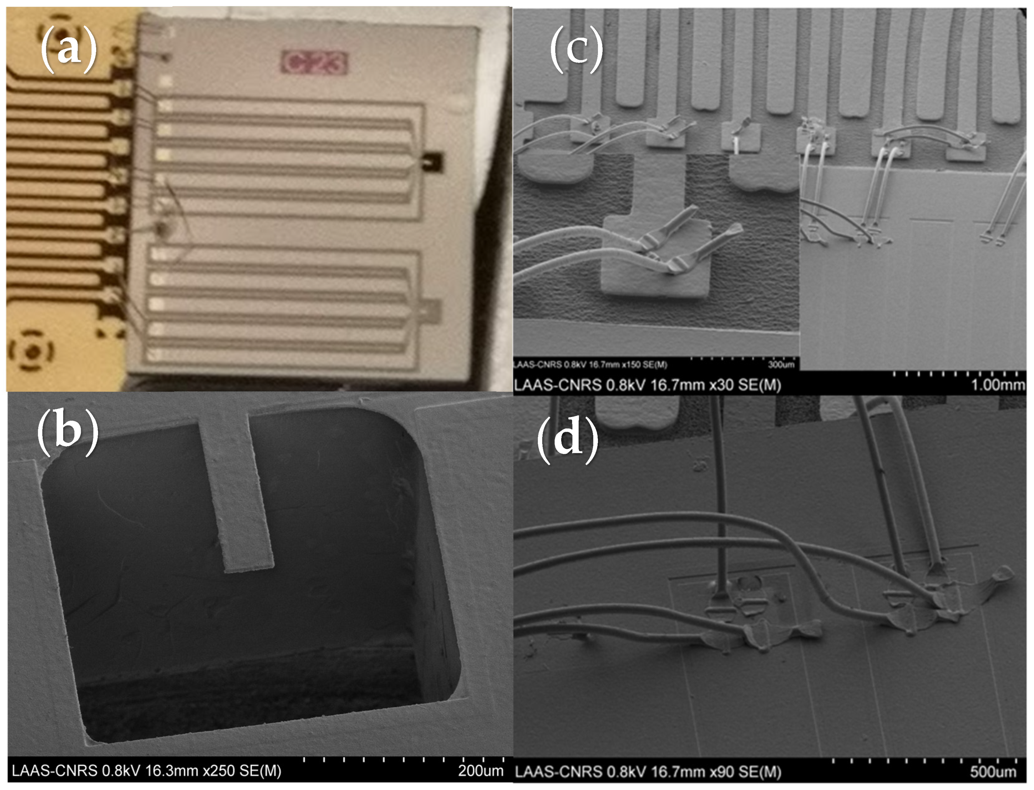
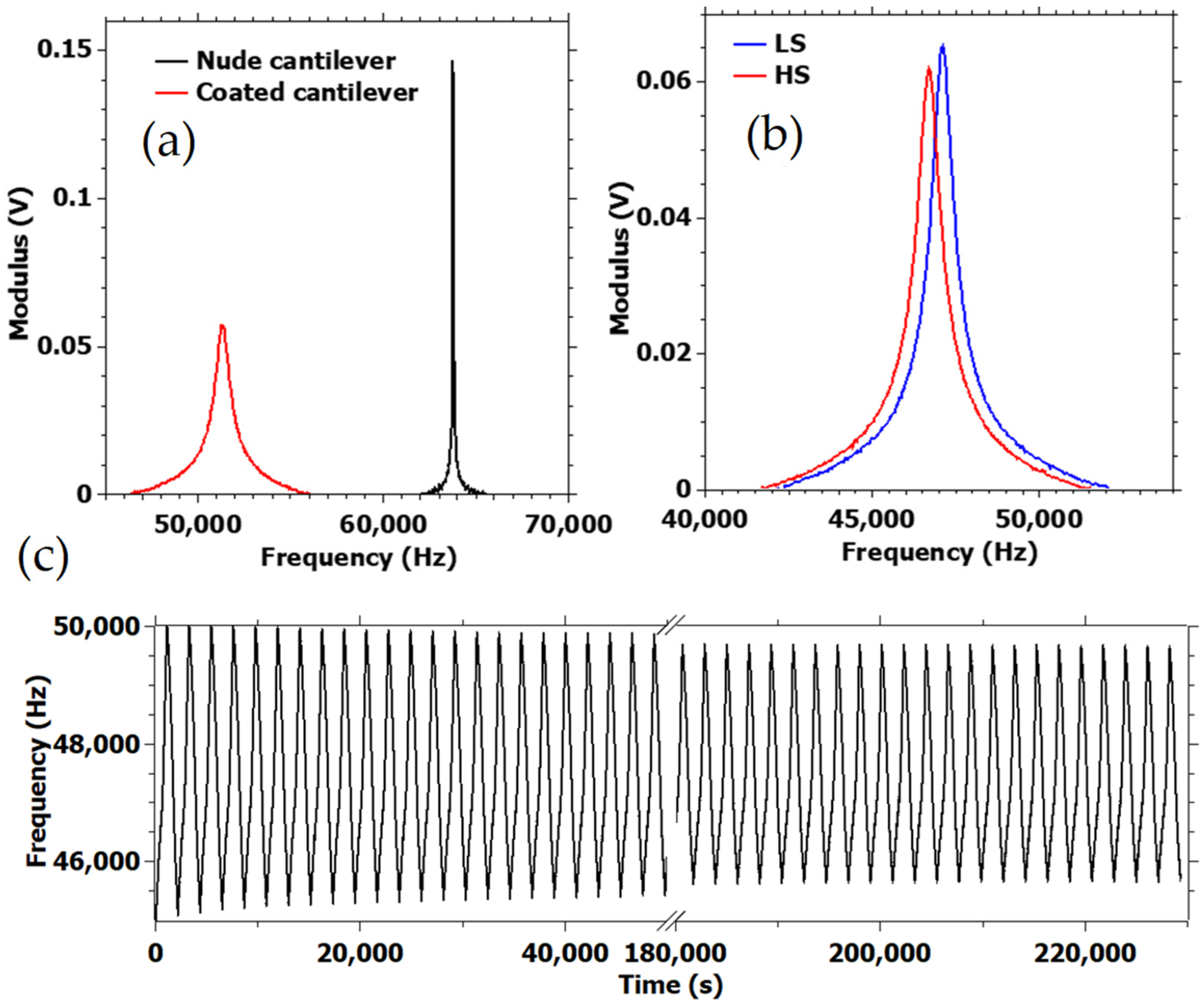
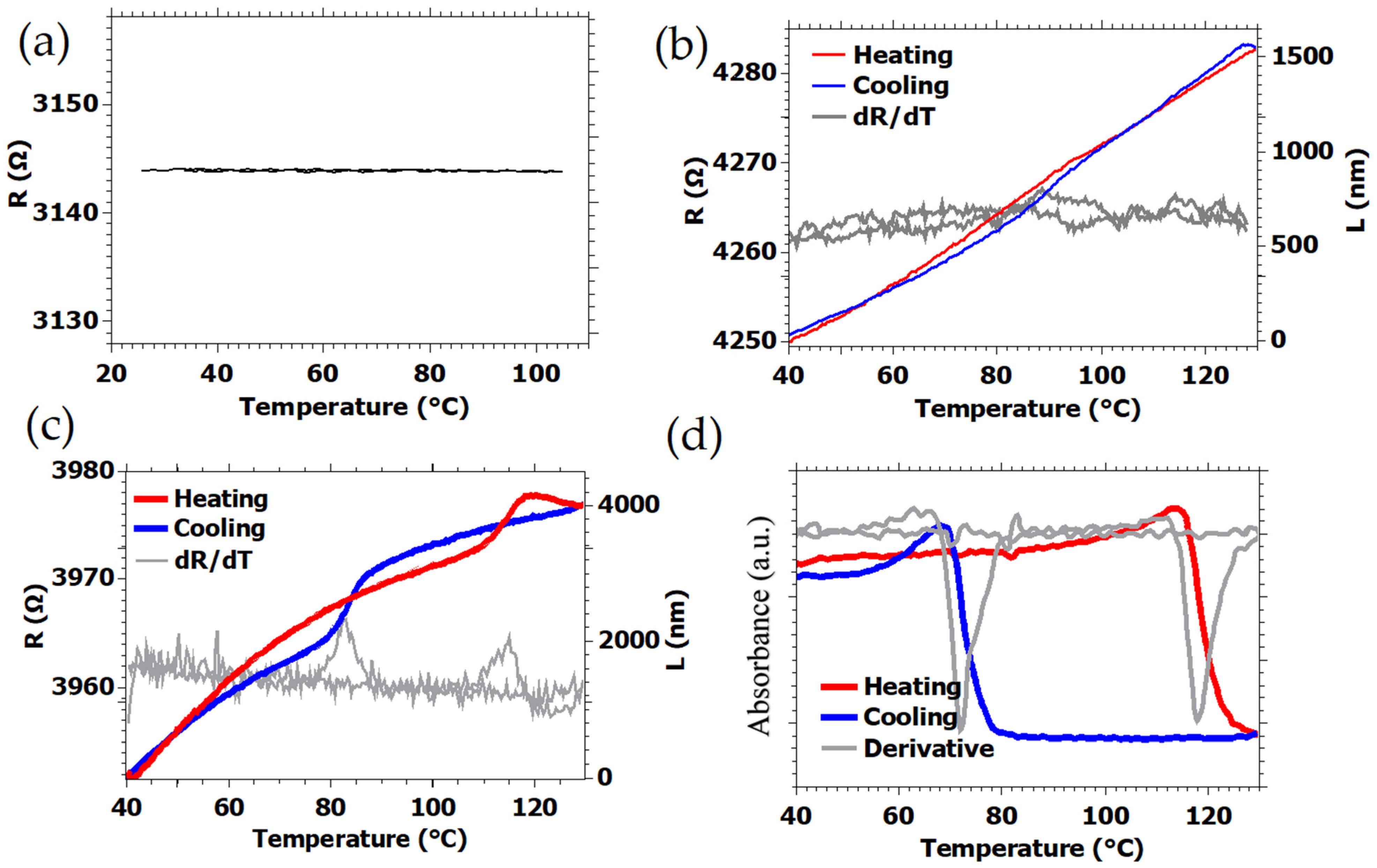
2. Results
3. Discussion
4. Materials and Methods
5. Conclusions
Author Contributions
Funding
Institutional Review Board Statement
Informed Consent Statement
Data Availability Statement
Conflicts of Interest
References
- Gütlich, P.; Hauser, A.; Spiering, H. Thermal and Optical Switching of Iron(II) Complexes. Angew. Chem. Int. Ed. 1994, 33, 2024–2054. [Google Scholar] [CrossRef]
- Gütlich, P.; Goodwin, H.A. Spin Crossover in Transition Metal Compounds I–III; Springer: Berlin/Heidelberg, Germany, 2004; Volume 233–235. [Google Scholar]
- Bousseksou, A.; Molnar, G.; Salmon, L.; Nicolazzi, W. Molecular spin crossover phenomenon: Recent achievements and prospects. Chem. Soc. Rev. 2011, 40, 3313–3335. [Google Scholar] [CrossRef] [PubMed]
- Halcrow, M.A. (Ed.) Spin-Crossover Materials: Properties and Applications; John Wiley & Sons: Oxford, UK, 2013. [Google Scholar]
- Collet, E.; Guionneau, P. Structural analysis of spin-crossover materials: From molecules to materials. Comptes Rendus Chim. 2018, 21, 1133–1151. [Google Scholar] [CrossRef]
- Guionneau, P. Crystallography and spin-crossover. A view of breathing materials. Dalton Trans. 2014, 43, 382–393. [Google Scholar] [CrossRef] [PubMed]
- Halcrow, M. Structure:function relationships in molecular spin-crossover complexes. Chem. Soc. Rev. 2011, 40, 4119–4142. [Google Scholar] [CrossRef]
- Shepherd, H.J.; Gural’Skiy, I.A.; Quintero, C.M.; Tricard, S.; Salmon, L.; Molnar, G.; Bousseksou, A. Molecular actuators driven by cooperative spin-state switching. Nat. Commun. 2013, 4, 2607. [Google Scholar] [CrossRef] [Green Version]
- Gural’Skiy, I.A.; Quintero, C.M.; Costa, J.S.; Demont, P.; Molnar, G.; Salmon, L.; Shepherd, H.; Bousseksou, A. Spin crossover composite materials for electrothermomechanical actuators. J. Mater. Chem. C 2014, 2, 2949–2955. [Google Scholar] [CrossRef] [Green Version]
- Chen, Y.-C.; Meng, Y.; Ni, Z.-P.; Tong, M.-L. Synergistic electrical bistability in a conductive spin crossover heterostructure. J. Mater. Chem. C 2014, 3, 945–949. [Google Scholar] [CrossRef]
- Manrique-Juarez, M.D.; Rat, S.; Mathieu, F.; Saya, D.; Séguy, I.; Leïchlé, T.; Nicu, L.; Salmon, L.; Molnar, G.; Bousseksou, A. Microelectromechanical systems integrating molecular spin crossover actuators. Appl. Phys. Lett. 2016, 109, 061903. [Google Scholar] [CrossRef]
- Manrique-Juarez, M.D.; Mathieu, F.; Shalabaeva, V.; Cacheux, J.; Rat, S.; Nicu, L.; Leïchlé, T.; Salmon, L.; Molnár, G.; Bousseksou, A. A Bistable Microelectromechanical System Actuated by Spin-Crossover Molecules. Angew. Chem. Int. Ed. 2017, 56, 8074–8078. [Google Scholar] [CrossRef]
- Manrique-Juárez, M.D.; Mathieu, F.; Laborde, A.; Rat, S.; Shalabaeva, V.; Demont, P.; Thomas, O.; Salmon, L.; Leïchlé, T.; Nicu, L.; et al. Micromachining-Compatible, Facile Fabrication of Polymer Nanocomposite Spin Crossover Actuators. Adv. Funct. Mater. 2018, 28, 1801970. [Google Scholar] [CrossRef]
- Mikolasek, M.; Manrique-Juarez, M.D.; Shepherd, H.J.; Ridier, K.; Rat, S.; Shalabaeva, V.; Bas, A.-C.; Collings, I.E.; Mathieu, F.; Cacheux, J.; et al. Complete Set of Elastic Moduli of a Spin-Crossover Solid: Spin-State Dependence and Mechanical Actuation. J. Am. Chem. Soc. 2018, 140, 8970–8979. [Google Scholar] [CrossRef] [Green Version]
- Urdampilleta, M.; Ayela, C.; Ducrot, P.-H.; Rosario-Amorin, D.; Mondal, A.; Rouzières, M.; Dechambenoit, P.; Mathonière, C.; Mathieu, F.; Dufour, I.; et al. Molecule-based microelectromechanical sensors. Sci. Rep. 2018, 8, 1–6. [Google Scholar] [CrossRef]
- Dugay, J.; Giménez-Marqués, M.; Venstra, W.J.; Torres-Cavanillas, R.; Sheombarsing, U.N.; Manca, N.; Coronado, E.; Van Der Zant, H.S.J. Sensing of the Molecular Spin in Spin-Crossover Nanoparticles with Micromechanical Resonators. J. Phys. Chem. C 2019, 123, 6778–6786. [Google Scholar] [CrossRef]
- Piedrahita-Bello, M.; Angulo-Cervera, J.E.; Courson, R.; Molnár, G.; Malaquin, L.; Thibault, C.; Tondu, B.; Salmon, L.; Bousseksou, A. 4D printing with spin-crossover polymer composites. J. Mater. Chem. C 2020, 8, 6001–6005. [Google Scholar] [CrossRef]
- Molnár, G.; Rat, S.; Salmon, L.; Nicolazzi, W.; Bousseksou, A. Spin Crossover Nanomaterials: From Fundamental Concepts to Devices. Adv. Mater. 2018, 30, 1703862. [Google Scholar] [CrossRef]
- Rat, S.; Piedrahita-Bello, M.; Salmon, L.; Molnár, G.; Demont, P.; Bousseksou, A. Coupling Mechanical and Electrical Properties in Spin Crossover Polymer Composites—Supporting information. Adv. Mater. 2018, 30, 1705275. [Google Scholar] [CrossRef] [Green Version]
- Piedrahita-Bello, M.; Martin, B.; Salmon, L.; Molnár, G.; Demont, P.; Bousseksou, A. Mechano–Electric coupling in P(VDF–TrFE)/spin crossover composites. J. Mater. Chem. C 2020, 8, 6042–6051. [Google Scholar] [CrossRef]
- Suleimanov, I.; Costa, J.S.; Molnár, G.; Salmon, L.; Fritsky, I.; Bousseksou, A. Effect of ligand substitution in [Fe(H-trz)2(trz)]BF4 spin crossover nanoparticles. Fr. Ukr. J. Chem. 2015, 3, 66–72. [Google Scholar] [CrossRef] [Green Version]
- Létard, J.-F.; Guionneau, P.; Goux-Capes, L. Towards Spin Crossover Applications. Top. Curr. Chem. 2006, 235, 221–249. [Google Scholar] [CrossRef]
- Alava, T.; Mathieu, F.; Mazenq, L.; Soyer, C.; Remiens, D.; Nicu, L. Silicon–Based micromembranes with piezoelectric actuation and piezoresistive detection for sensing purposes in liquid media. J. Micromech. Microeng. 2010, 20, 075014. [Google Scholar] [CrossRef]
- Dufour, I.; Maali, A.; Amarouchene, Y.; Ayela, C.; Caillard, B.; Darwiche, A.; Guirardel, M.; Kellay, H.; Lemaire, E.; Mathieu, F.; et al. The Microcantilever: A Versatile Tool for Measuring the Rheological Properties of Complex Fluids. J. Sens. 2012, 2012, 719898. [Google Scholar] [CrossRef] [Green Version]
- Whiting, R.; Angadi, M.; Tripathi, S. Evaluation of elastic moduli in thin-film/substrate systems by the two-layer vibrating reed method. Mater. Sci. Eng. B 1995, 30, 35–38. [Google Scholar] [CrossRef]
- Vanhellemont, J.; Swarnakar, A.K.; Van Der Biest, O. Temperature Dependent Young’s Modulus of Si and Ge. ECS Trans. 2014, 64, 283–292. [Google Scholar] [CrossRef]
- Hafner, J.; Teuschel, M.; Schneider, M.; Schmid, U. Origin of the strong temperature effect on the piezoelectric response of the ferroelectric (co-)polymer P(VDF70-TrFE30). Polymer 2019, 170, 1–6. [Google Scholar] [CrossRef]
- Timoshenko, S. Analysis of Bi-Metal Thermostats. J. Opt. Soc. Am. 1925, 11, 233–255. [Google Scholar] [CrossRef]
- Stoney, G.G. The tension of metallic films deposited by electrolysis. Proc. R. Soc. London. Ser. A Math. Phys. Sci. 1909, 82, 172–175. [Google Scholar] [CrossRef] [Green Version]


| [Fe(Htrz)2(trz)](BF4)@ P(VDF-TrFE) [This Work] | [Fe(Htrz)2(trz)](BF4)@ SU8 [13] | |
|---|---|---|
| Length, l (µm) | 150 | 840 |
| Si cantilever thickness, ts (µm) | 2 | 20 |
| Composite film thickness, tf (µm) | 1.5 | 3.5 |
| Width, w (µm) | 50 | 100 |
| Particle weight fraction, f (wt%) | 33 | 30 |
| Density, ρ (kg/m3) | 1800 | 1400 |
| Tip deflection at SCO δ (µm) | 0.88 | 3.65 |
| Cantilever curvature due to SCO k (m−1) | 80 | 10 |
| Actuation strain due to SCO, εSCO (%) | 1.3 | 1.0 |
| Actuation stress due to SCO, σSCO (MPa) | 7.7 | 43 * |
| Young’s modulus, E (GPa) at 40 °C | 3.2 | - |
| Young’s modulus, E (GPa) at 95 °C | 0.5 | 3.2 |
| Work density due to SCO, w/v (mJ/cm3) | 40 | 140 |
Publisher’s Note: MDPI stays neutral with regard to jurisdictional claims in published maps and institutional affiliations. |
© 2021 by the authors. Licensee MDPI, Basel, Switzerland. This article is an open access article distributed under the terms and conditions of the Creative Commons Attribution (CC BY) license (https://creativecommons.org/licenses/by/4.0/).
Share and Cite
Angulo-Cervera, J.E.; Piedrahita-Bello, M.; Mathieu, F.; Leichle, T.; Nicu, L.; Salmon, L.; Molnár, G.; Bousseksou, A. Investigation of the Effect of Spin Crossover on the Static and Dynamic Properties of MEMS Microcantilevers Coated with Nanocomposite Films of [Fe(Htrz)2(trz)](BF4)@P(VDF-TrFE). Magnetochemistry 2021, 7, 114. https://doi.org/10.3390/magnetochemistry7080114
Angulo-Cervera JE, Piedrahita-Bello M, Mathieu F, Leichle T, Nicu L, Salmon L, Molnár G, Bousseksou A. Investigation of the Effect of Spin Crossover on the Static and Dynamic Properties of MEMS Microcantilevers Coated with Nanocomposite Films of [Fe(Htrz)2(trz)](BF4)@P(VDF-TrFE). Magnetochemistry. 2021; 7(8):114. https://doi.org/10.3390/magnetochemistry7080114
Chicago/Turabian StyleAngulo-Cervera, José Elías, Mario Piedrahita-Bello, Fabrice Mathieu, Thierry Leichle, Liviu Nicu, Lionel Salmon, Gábor Molnár, and Azzedine Bousseksou. 2021. "Investigation of the Effect of Spin Crossover on the Static and Dynamic Properties of MEMS Microcantilevers Coated with Nanocomposite Films of [Fe(Htrz)2(trz)](BF4)@P(VDF-TrFE)" Magnetochemistry 7, no. 8: 114. https://doi.org/10.3390/magnetochemistry7080114