Laser Powder Bed Fusion of Precipitation-Hardened Martensitic Stainless Steels: A Review
by
 ,
,
Le Zai
1,2,†, 
Chaoqun Zhang
1,*,†,
Yiqiang Wang
3,
Wei Guo
4,††,
Daniel Wellmann
1,5,
Xin Tong
2 and
Yingtao Tian
5 1
School of Mechanical Engineering, Shanghai Jiao Tong University, Shanghai 200240, China
2
College of Materials Science and Engineering, Chongqing University, Chongqing 400045, China
3
United Kingdom Atomic Energy Authority, Culham Science Centre, Abingdon, OX14 3DB, UK
4
Laser Processing Research Centre, School of Mechanical, Aerospace and Civil Engineering, The University of Manchester, Manchester, M13 9PL, UK
5
Department of Engineering, Lancaster University, Bailrigg, Lancaster, LA1 4YW, UK
*
Author to whom correspondence should be addressed.
†
Le Zai and Chaoqun Zhang contribute equally to this paper.
††
Dr. Wei Guo is working at The Welding Institute (TWI) Ltd. as a Senior Project Leader.
Metals 2020, 10(2), 255; https://doi.org/10.3390/met10020255
Submission received: 22 December 2019
/
Revised: 7 February 2020
/
Accepted: 10 February 2020
/
Published: 14 February 2020
(This article belongs to the Special Issue AM-PBF Processes and Joining Similar/Dissimilar PBF Materials: Quo Vadis?)
Abstract
:Martensitic stainless steels are widely used in industries due to their high strength and good corrosion resistance performance. Precipitation-hardened (PH) martensitic stainless steels feature very high strength compared with other stainless steels, around 3-4 times the strength of austenitic stainless steels such as 304 and 316. However, the poor workability due to the high strength and hardness induced by precipitation hardening limits the extensive utilization of PH stainless steels as structural components of complex shapes. Laser powder bed fusion (L-PBF) is an attractive additive manufacturing technology, which not only exhibits the advantages of producing complex and precise parts with a short lead time, but also avoids or reduces the subsequent machining process. In this review, the microstructures of martensitic stainless steels in the as-built state, as well as the effects of process parameters, building atmosphere, and heat treatments on the microstructures, are reviewed. Then, the characteristics of defects in the as-built state and the causes are specifically analyzed. Afterward, the effect of process parameters and heat treatment conditions on mechanical properties are summarized and reviewed. Finally, the remaining issues and suggestions on future research on L-PBF of martensitic precipitation-hardened stainless steels are put forward.
1. Introduction
Precipitation-hardened (PH) stainless steels (for example, 17–4 PH steel, ≤0.07 C, 15-17.5 Cr, 3-5 Ni, 3-5 Cu, ≤1 Mn, Si, 0.15-0.45 Nb, balance Fe in wt.%) were invented to meet the demand of the rapid development of the aerospace industry since the 1940s [1,2]. They have much higher strength than ferritic or austenitic stainless steels [3]. The main precipitation and hardening elements in martensitic stainless steels are copper (Cu) and niobium (Nb). The hardening process is dominated by the Cu precipitate phase in the martensite matrix after a high-temperature solid solution and subsequent aging heat treatment [4,5,6,7,8]. A wide range of mechanical properties of precipitation-hardened (PH) stainless steels (SS) can be developed through heat treatment at different temperatures, since various types of microstructures can be obtained with different heat treatment processes [9]. The typical temperature range for aging heat treatment for this alloy is 480-620 °C [1]. Under the H900 condition (aging temperature: 482 °C, time: 1 h), the precipitation in 17–4 PH stainless steel begins with Cu-rich precipitates (bcc, body center cubic) that maintain a coherent relationship with the matrix, which would lead to an increase in tensile strength and toughness [4]. These precipitates can transform into non-coherent Cu-rich particles (fcc, face center cubic) after extended aging at 400 °C [5]. After experiencing over-aging, the precipitates are coarsened. The number of precipitates is reduced, and the coherence relationship is also destroyed [6,10]. These changes together lead to a decrease in mechanical strength, but an increase in ductility and impact toughness.
PH stainless steels are widely used in the aerospace industry [11,12], the marine industry [13], nuclear reactor components [14], chemical process equipment [15], and medical apparatus due to their high tensile strength, impact strength, fracture toughness, and corrosion resistance at typical service temperatures below 300 °C [15,16]. Most of these parts are important load-bearing components of heavy machinery in a demanding service environment. However, PH stainless steels have poor workability and machinability due to their high strength and high hardness, which result in a long production cycle and difficulties in obtaining desired shapes through conventional machining and forming processes [17].
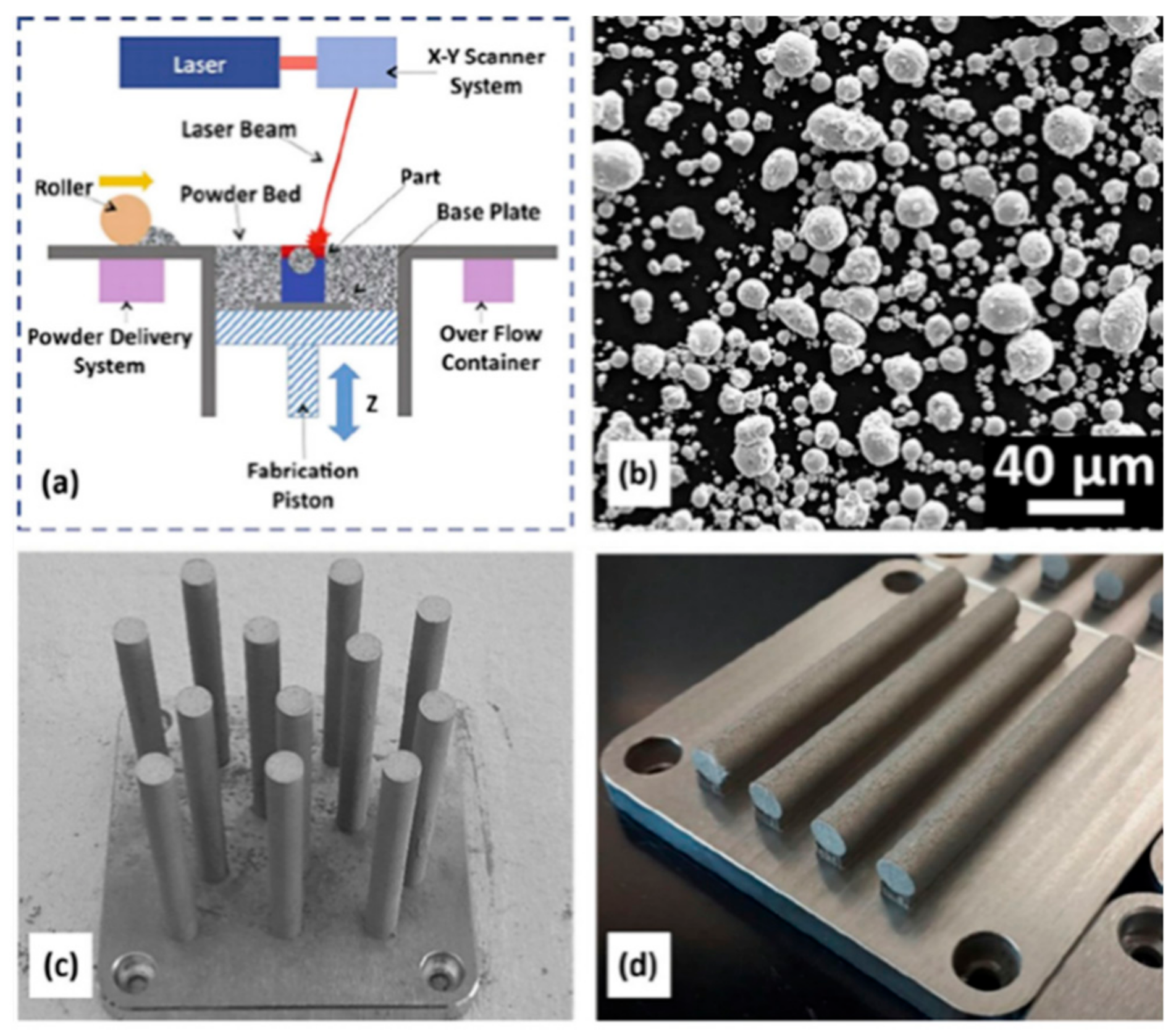
Due to the high strength and high hardness of PH steels, they are difficult to be manufactured via conventional machining processes. Additive manufacturing (AM) processes [18,19,20,21,22,23,24]] offer great new opportunities for producing high-strength PH steel parts with high geometric complexity [25]. Some metal AM processes are used for printing PH steel parts, including laser powder bed fusion (L-PBF) [17,26,27], wire arc additive manufacturing (WAAM) [28,29,30,31], and direct metal laser deposition (DMLD) [2]. Compared with L-PBF, the printing accuracy of DMLD is limited by the convergence size of the powder flow, and the forming accuracy of DLMD is lower than that of L-PBF. The forming accuracy of WAAM is much lower than that of L-PBF; thus, WAAM can only be used for manufacturing metal parts with simple geometric shapes; moreover, WAAMed parts generally require subsequent processing [32,33,34] to achieve satisfied surface quality. Thus, L-PBF is more suitable for producing PH steel parts with high geometric complexity than both WAAM and DMLD. L-PBF is an advanced additive manufacturing (AM) technique, which involves a layer-by-layer melting and solidification of a metal powder according to the sliced Computer Aided Design (CAD) model, and it is widely used for printing various metals [18,35,36,37,38,39,40,41,42,43,44,45,46,47,48,49,50,51,52,53,54,55,56,57,58,59,60,61]. L-PBF of stainless steels was widely studied in recent years, such as austenitic stainless steels 304 [62,63,64,65] and 316L [66,67,68,69,70,71,72,73,74,75,76,77,78,79,80,81,82,83,84,85,86], duplex stainless steels [87,88,89,90], and PH stainless steels [26,27,91,92,93,94,95,96,97,98]. During L-PBF, metallic powder is selectively melted and fused by a high-energy-density laser beam [99,100,101]. A schematic of the L-PBF process is shown in Figure 1a. L-PBF has significant advantages over traditional processing techniques [102,103]. The use of three-dimensional data, forming parts in the process, without the need for molds, is suitable for producing materials with complex geometries. In addition, the surface of the formed part is close to the sand casting situation and often adequate for the application [104]. In terms of cost and production cycle, significant savings in raw materials and total lead time can be achieved [105]. In terms of performance, the strength of the L-PBF part is often superior to casting and comparable to wrought parts [106,107]. The weldability and the austenitic/martensitic microstructure of PH stainless steels make it an attractive alloy for additive manufacturing (AM) processing [108]. Therefore, the manufacturing of PH stainless steel parts by L-PBF attracted broad interests from industry.
In order to obtain an almost fully dense and functional component, many process parameters, such as laser energy density, scanning strategy, powder bed preheating process, and build chamber atmosphere, need to be controlled carefully (Figure 1c,d). The volumetric laser energy density E (J/mm3), as defined in Equation (1), is critical and needs to be above a certain threshold.
where P (W) is the laser power, v (mm/s) is the laser scanning speed, h (mm) is the hatch spacing (i.e., the distance between laser scan lines), and t (mm) is the powder layer height [109].
There are many involved process and design parameters for L-PBF, including powder, laser power, scanning speed, scanning strategy, and part building orientation (Figure 1c,d). The quality of the formed parts is usually closely related to the additive manufacturing equipment, materials (powder material type, powder sphericity, powder fluidity, etc.), and process (process parameters, scanning strategy) [32,33,34,110,111,112,113,114]. Various combinations of these parameters result in parts experiencing a unique and complex thermal history, which results in a mixture of microstructures during the fabrication. For example, Irrinki et al. [115] studied the mechanical properties of L-PBF 17–4 PH stainless steel using gas- versus water-atomized powders. It was found that specimens built by gas-atomized powder had superior densification (87% to 97%), elongation (7% to 23%), and ultimate tensile strength (470 MPa to 850 MPa) at a laser energy density of 64 J/mm3. Specimens made by water-atomized powder were only as good as those made by gas-atomized powder when the powder bed energy density was increased to 104 J/mm3. Gu et al. [116] found that the porosity in L-PBFed 17–4 PH stainless steel increased with decreasing power (70–90 W) and scanning speed (287–800 mm/s) when the energy density was maintained at 61 J/mm3. Therefore, it is essential to investigate the interrelation between the L-PBF process and the resulting microstructures. In this review, the microstructure of L-PBFed PH stainless steels is reviewed first. Afterward, previous investigations on phase transformation behaviors, as well as the effect of process parameters and post-heat treatments on mechanical properties, are summarized and reviewed.
2. Microstructure
The L-PBF fabricated parts show a unique microstructure compared with the conventional method. There are three phases in PH stainless steels: δ-ferrite (bcc), austenite (fcc), and martensite (bcc; austenitic transformation occurs when the temperature is below MS). The solid-state phase transformation of PH stainless steels typically follows a δ-ferrite → austenite → martensite sequence. However, large undercooling rates (105–106 K/s) [117] render the phase diagram invalid, and pre-solidified materials undergo cyclic heating/cooling during the L-PBF process, which results in non-equilibrium microstructures for 17–4 PH stainless steels. Thus, the microstructures of materials fabricated by the L-PBF method are different from those of conventional processing materials. In addition, L-PBF parts exhibit anisotropic properties. Generally the mechanical properties in the build direction differ from those in the plane of the build [98].
2.1. Microstructure in as L-PBFed State
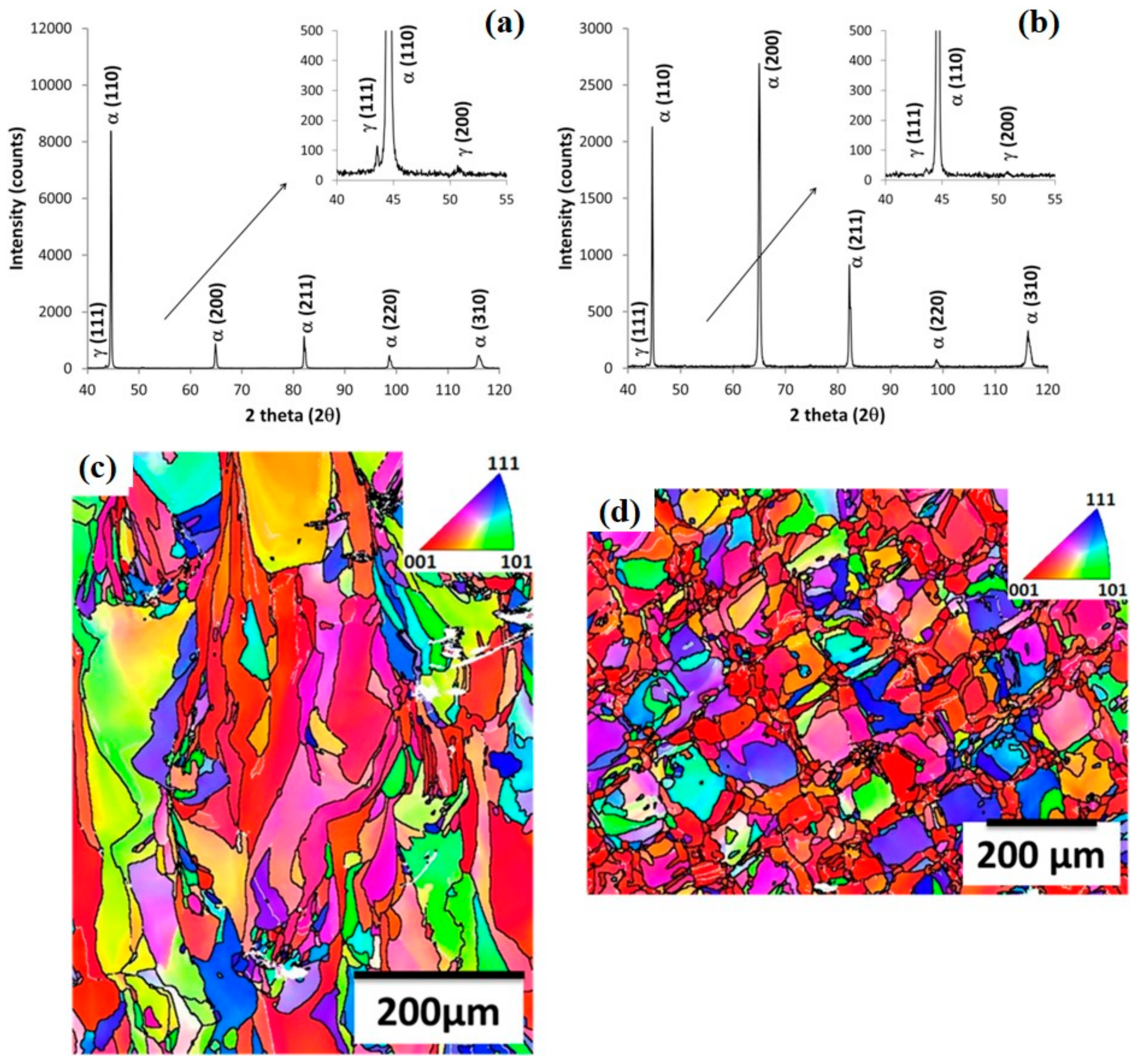
The as-built PH stainless-steel microstructure consists of columnar grains, which are oriented parallel to the build direction following the vertical thermal gradient between the melt pool and the solidified lower layers. These columnar shaped grains can have a size of several hundreds of micrometers (Figure 2c,d), thus extending over several powder layers. This means that, during the molten pool solidification, the freshly formed crystals have an epitaxial growth by adopting the orientation of the lower previously formed grains [98]. PH stainless-steel AM samples exhibit columnar bcc grains with strong overall [118] texture and small equi-axed fcc grains at molten pool boundaries, as shown in Figure 4.
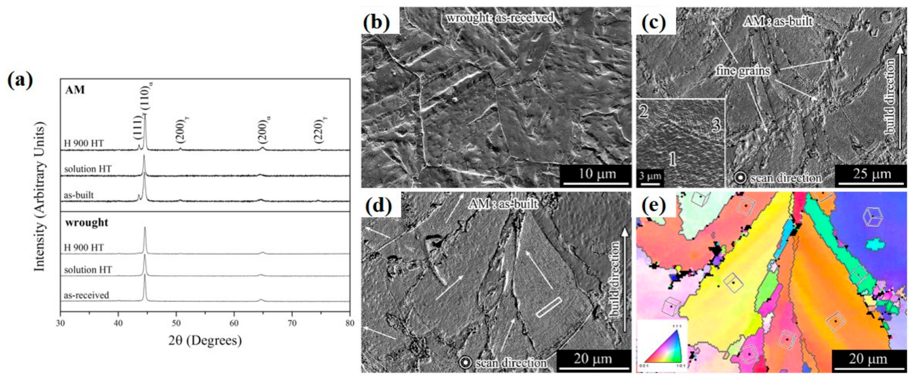
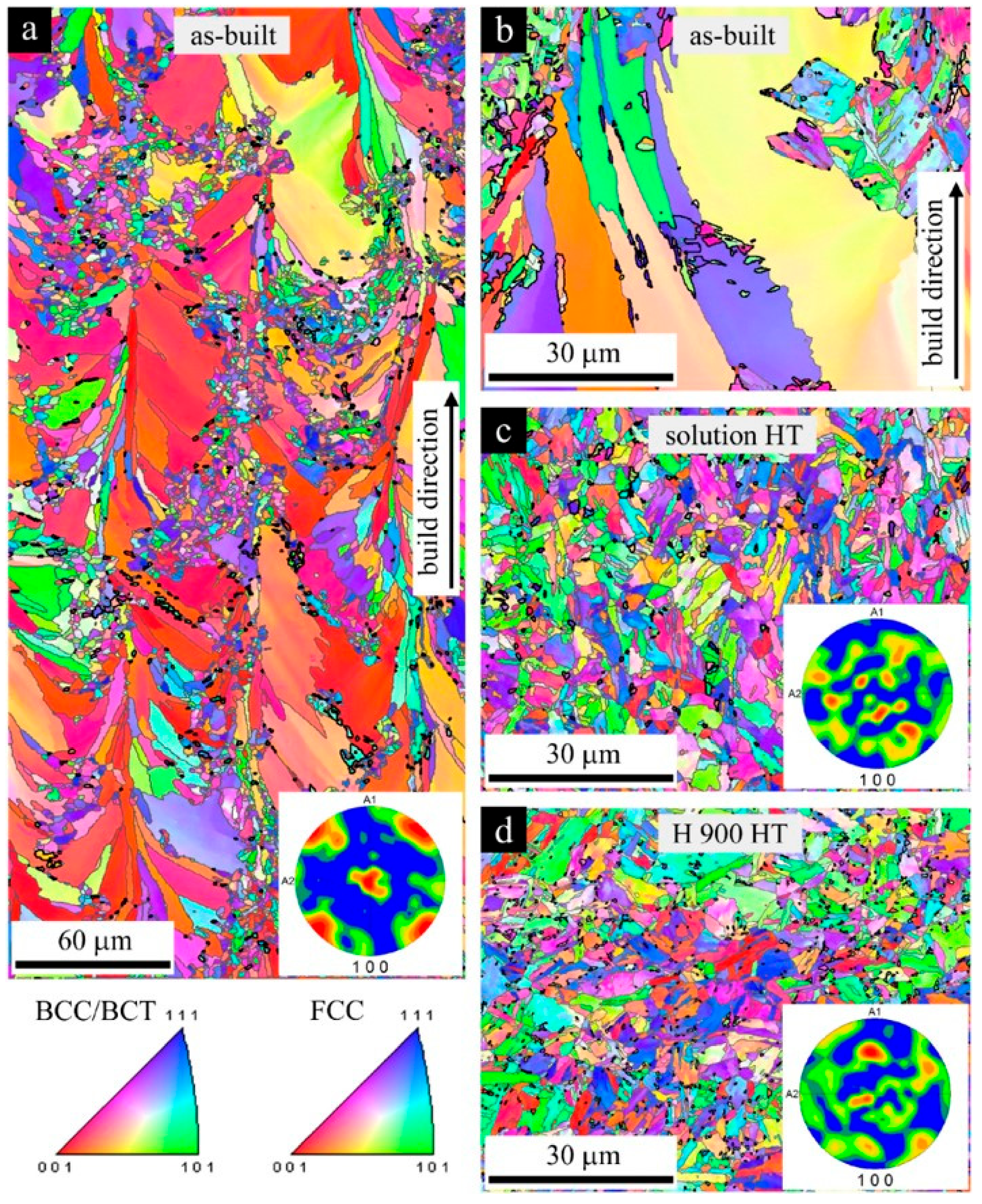
Previous work on as-built PH SS AM components revealed a non-equilibrium microstructure, as well as strong differences in texture parallel and perpendicular to the build direction, due to the very high cooling rates [17,99,104,105,106,107,115]. Some of the literature claimed that the as-built microstructure via L-PBF contains martensite and retained austenite (metastable phase at room temperature) [26,27,95,98,119,120,121,122], completely different from that of a wrought 17–4 PH stainless steel, which is fully martensitic. However, Alnajjar et al. [117] and Sun et al. [123] respectively reported a fully δ-ferrite microstructure (based on Figure 2) and a dominantly ferrite microstructure (Figure 3) with small grains at melt-pool boundaries comprising bcc martensitic laths and equiaxed fcc austenite grains. Strictly speaking, all the above statements on phase composition cannot be warranted by their Electron Backscatter Diffraction (EBSD) and X-ray diffraction (XRD) data, since the martensite in the 17–4 steel has a nearly bcc structure (essentially without interstitials, very low carbon concentration) and appears as “ferrite” in X-ray diffraction and in EBSD. Significant challenges exist in accurately identifying δ-ferrite, ferrite, and martensite in as-built 17–4 PH SS steel samples due to the high similarity in the crystal structure. Due to the inconsistence and controversy on the phase composition of as-built 17–4 PH SS steel as reported in aforementioned papers, it is very necessary to deeply study the microstructure of as-built 17–4 PH, especially clearly distinguishing and identifying the martensite phase and δ-ferrite phase. Very recently, Vunnam et al. [91] carried out some meritorious work on this. They used EBSD image quality (IQ) to distinguish martensite and ferrite phases [91,124]. The martensite region and grain boundary region usually have low IQ values. Vunnam et al. [91] reported that austenite, ferrite, and martensite were all detected in different as-built 17–4 PH samples produced using different 17–4 powders with slightly different chemical compositions (mainly different Creq/Nieq values). Vunnam et al. [91] found that the δ-ferrite-to-austenite phase transformation kinetics depend on the initial powder chemical composition. Depending on the Creq/Nieq value of the initial powder, the residual δ-ferrite volume fraction varied approximately from 95% to below 25%. The very sensitive effect of powder chemical composition was not recognized before the study of Vunnam et al. [91] and may explain the variability in phase composition results reported in previous investigations. Their findings are useful for achieving fully martensitic parts in the as-built state by controlling the composition of the powder. As a result, post-heat treatments may be saved in same cases for lower cost (Figure 4).
For 17–4 PH stainless steel, the starting and ending temperatures of martensitic transformation Ms (132 °C) and Mf (32 °C) are higher than room temperature, which leads to complete transformation of austenite at room temperature [14]. For the AM specimens, the cooling rates in L-PBF are high enough to form a complete martensite structure [122]. However, some regions of martensite formed during the L-PBF process would be heat-affected by laser scanning paths, resulting in the formation of reverted austenite (inter-lath austenite). Hence, the as-L-PBFed sample could possess a relatively small volume of reverted austenite. Furthermore, other characteristics, such as the residual stresses at the grain boundaries, dislocation density, and grain size, may reduce the MS and Mf temperatures to below room temperature. All of these factors would lead to an incomplete transformation of the austenite phase [95,98,117]. The presence of austenite-stabilizing elements such as N in the powder and (as N2 gas) in the build chamber would also contribute to that phenomenon [96]. Additionally, some factors such as initial conditions of the powder, building orientation, chamber atmosphere, and subsequent processing and heat treatment conditions demonstrated significant effects on the austenite-martensite transformation and the amount of retained austenite in L-PBF 17–4 PH stainless steel. In general, the high retained austenite (RA) content (after printing) is related to the following factors: the presence of nitrogen plays a role in stabilizing the austenite, but also segregation effects resulting from rapid cooling could be responsible for the high RA fraction. Segregation would result in different local chemical compositions (favoring local RA); heat treatment would nullify the effect by chemical homogenization. Below is a detailed discussion of the above factors.
- (1)
- Initial Atomizing Media of Powder and Building Chamber Atmosphere
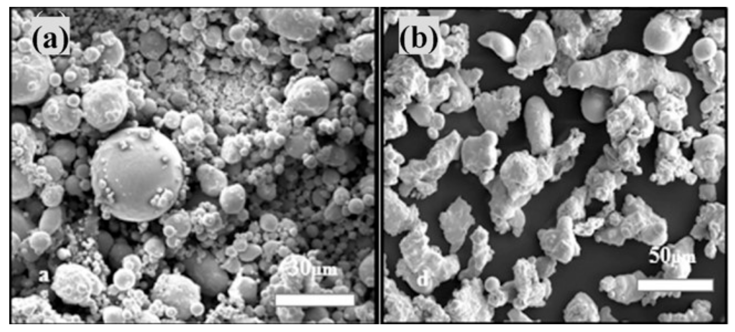
Powders obtained from gas-atomized (argon-atomized and nitrogen-atomized) or water-atomized techniques were proven to be feasible for L-PBF because of their respective advantages [115]. As shown in Figure 5, gas-atomized powders (Figure 5a) are spherical particles, while water-atomized powders have a mixture of semi-spherical and rounded shapes with relatively clean particles without satellites (Figure 5b). The building chamber atmosphere (argon or nitrogen) is essential to prevent powder oxidation during the L-PBF process at elevated temperature. The effects of powder types associated with manufacturing atmosphere on the final microstructure of L-PBF 17–4 PH steels are listed in the Table 1.
Despite the differences in the results of the existing literature, the effect of different atomizing media on the microstructure of powder is enormous [95,96]. Nitrogen-atomized powder makes it easier to obtain austenite than argon-atomized powder, and water-atomized powder can obtain the maximum volume fraction of austenite in three atomization modes. Among the three atomizing media, the cooling rates for water-atomized powder are 10-100 times larger than gas-atomized powders [126] (a high cooling rate refines the grains and suppresses the austenite transformation). The carbon content of the water-atomized powder (0.208 wt.%) is much higher than that of the gas-atomized powder (0.03 wt.%) [93], and the relatively higher carbon content lowers the MS temperature and suppresses the production of martensite. The combination of these two factors leads to a higher austenite content in raw powder materials. Moreover, the formation of retained austenite appears to be highly likely due to the absorption of nitrogen, an austenite stabilizer [95,96,127], from both powder atomizing media and chamber atmosphere, resulting in decreased martensite.
- (2)
- Energy density
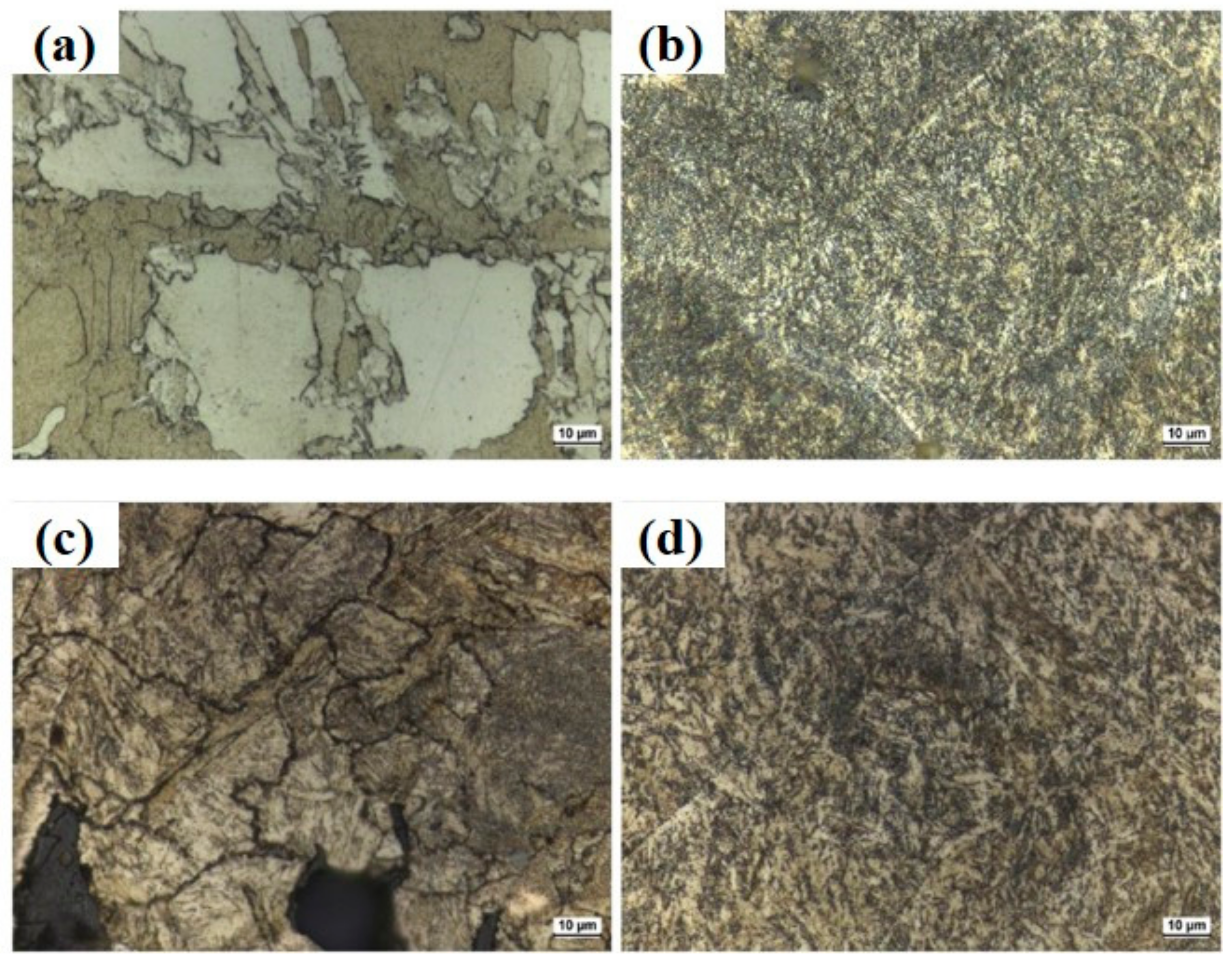
Table 2 shows the relative phase content of as-built L-PBF parts obtained by gas-atomized and water-atomized powder under different energy densities. When the energy density is increased from 64 J/mm3 to 104 J/mm3, the phase remains unchanged in the gas-atomized case, i.e., fully martensitic. The amount of residual austenite phase in water atomized powder printing is inversely proportional to the laser energy density. This trend may be caused by the increased peak temperature in the melt pool due to the increased heat input. The microstructure of the deposited sample at 64 J/mm3 volumetric laser energy density exhibited a coarser lath martensitic structure, as shown in Figure 6a, and an ultrafine martensitic structure was observed, as shown in Figure 6b. Figure 6 shows that a significant amount of the large porosity can be attributed to the lack of fusion at a lower energy density of 64 J/mm3. In the L-PBF process, martensite is formed when austenite is rapidly cooled below the MS temperature according to the continuous cooling transformation (CCT) curve.
- (3)
- Building orientation
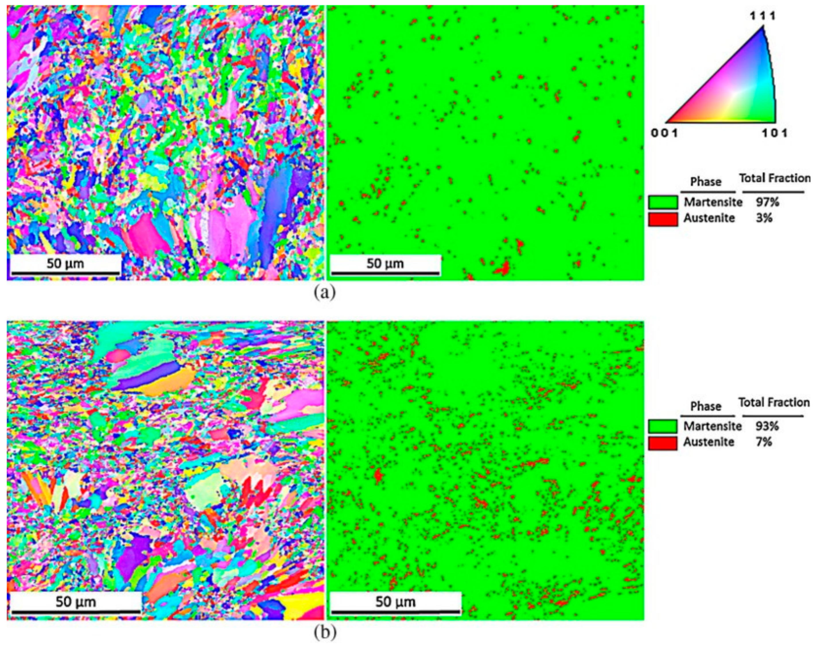
The relationship between the aspect ratio of the part and the building orientation would affect its thermal history during the AM process. For example, in the case of a cylindrical rod, the sample in the vertical orientation has a higher building aspect ratio (tall but slim), while the sample in the horizontal orientation has a lower aspect ratio (short and wide) [26]. Eventually, this may affect its final grain sizes and phase fraction [128]. A larger amount of retained austenite can be found in horizontally orientated samples (93% martensite +7% austenite) than in vertically orientated samples (97% martensite + 3% austenite) in EBSD maps of selected areas, as reported by Yadollahi et al. (Figure 7) [26]. The difference in austenite volume fraction is because the deposited area between layers of the horizontal sample is larger, and the time interval between melted layers is evidently longer as compared to vertical ones, which allows more heat energy to dissipate through the surrounding space, powder bed, and previously melted layer. Therefore, the initial temperature difference between the molten pool and the previously solidified surface is larger, which leads to a higher cooling rate of horizontal samples and refinement of austenite grains.
- (4)
- Laser scanning pattern
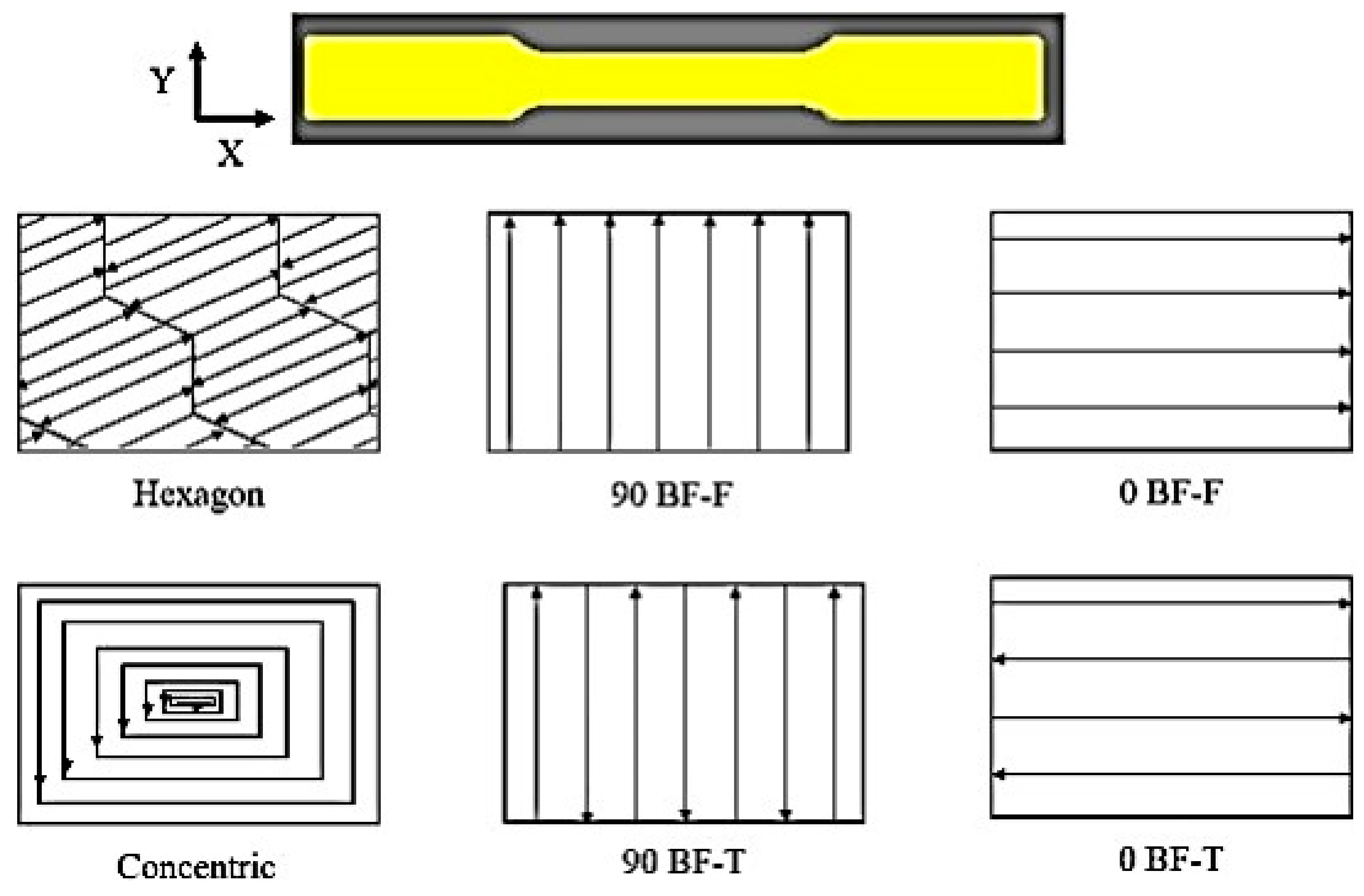
The laser scanning strategy can change the thermal history of each layer, thus affecting the porosity and microstructure of L-PBF parts [129]. Although the energy density input to the powder bed remains unchanged, the total distance that the laser travels varies with the strategy due to the geometric constraints of the specific scanning strategy. In addition, the scanning time of each layer is also different. Six different laser scanning strategies are shown in Figure 8 [129]. Except for the hexagonal scanning strategy, the grains of all scanning strategies were textured along the build direction due to the repetitive nature of the line scanning strategy. Table 3 [129] shows the average austenite fraction corresponding to different scanning strategies.
2.2. Microstructure after Heat Treatments
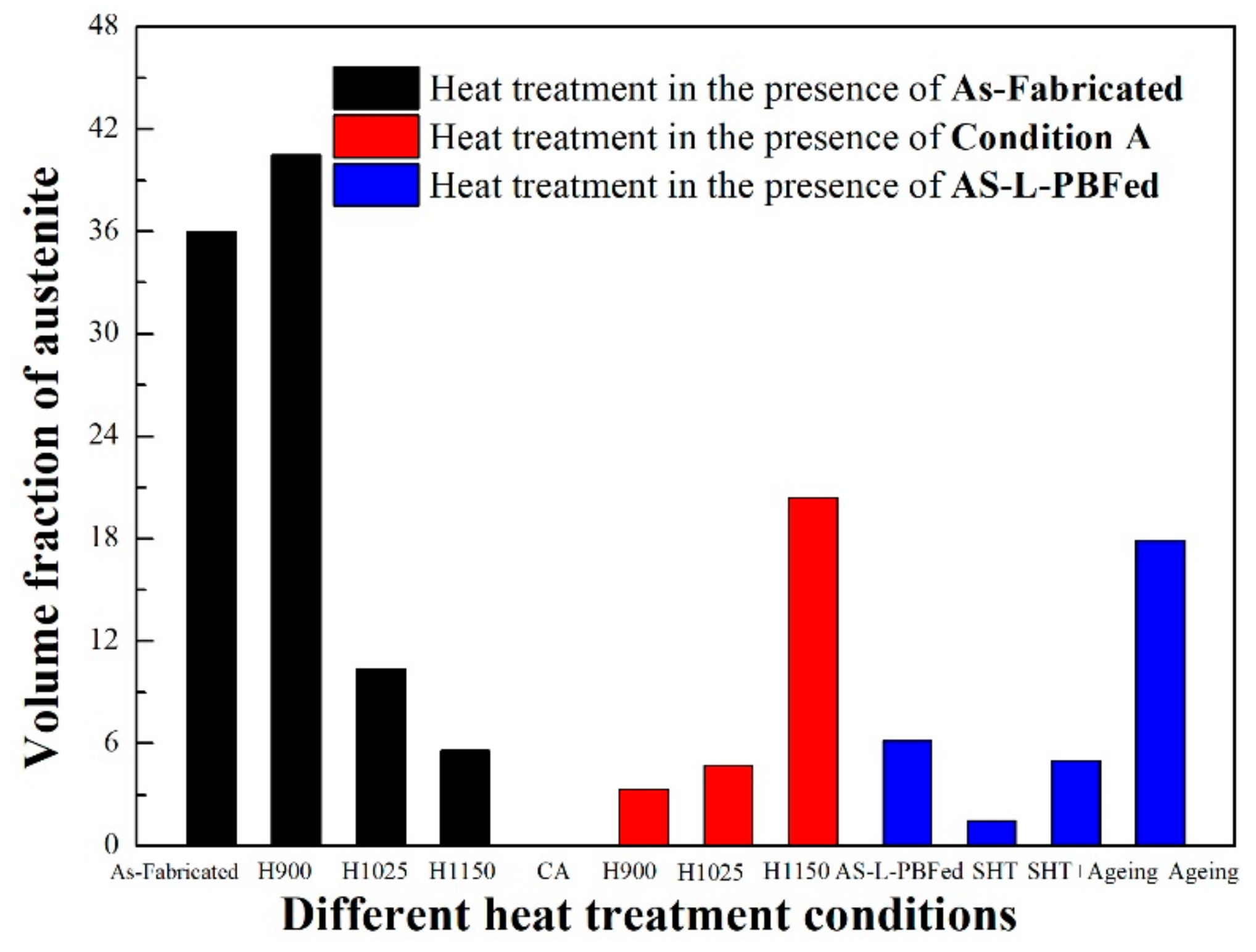
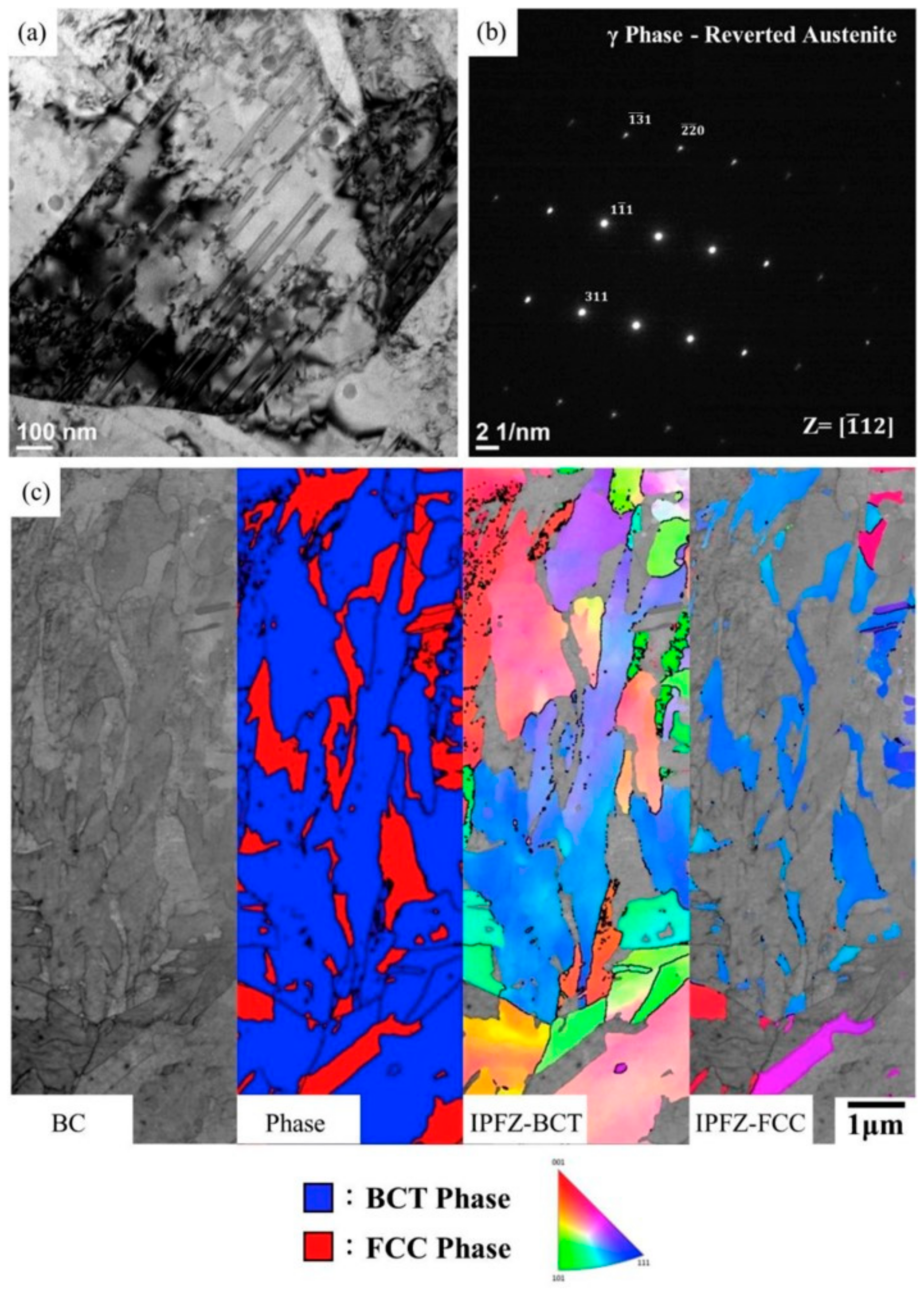
The unique heating, melting, and solidification conditions during the additive manufacturing process induce microstructural heterogeneities, anisotropy, and residual stresses in almost all cases. Post-heat treatments are required to mitigate these effects, especially for PH stainless steels strengthened by the precipitation of highly dispersed Cu-rich particles. Post-heat treatment has an important effect on the microstructure of L-PBF parts. For example, solution annealing and the aging process can recrystallize and homogenize the microstructure to remove the interface region. The interface area of the deposited layer and the boundary of the molten pool disappear completely. Sun [123] reported that the microstructure of the solid solution heat-treated AM sample is finer and more uniform than that of the AM sample. The {100} texture of the original columnar ferrite grains was eliminated, and the volume fraction of the retained austenite was reduced by condition A (solutionizing treatment), as shown in Figure 4c,d. Different heat treatment conditions have a significant effect on the content of retained austenite, as shown in Table 4 and Figure 9. Solution heat treatment is sufficient to eliminate the metastable austenite phase. In this case, the subsequent aging treatment of the material results in an increase in yield and tensile strength. With the increase in aging temperature and time, the volume percentage of austenite is as high as 20.4% [27,122]. The copper-rich precipitates can be formed within the martensite matrix during the aging process, but this does not occur spontaneously in the as-built sample. Upon direct over-aging 17–4 PH stainless steel to temperatures above peak-aging, this state with the extension of temperature and time returns the martensite matrix to the softer austenite phase, as shown in Figure 10a. This figure shows Transmission Electron Microscope (TEM) images of L-PBF + direct aging specimens with an overview of the microstructure of both martensite and austenite. The selected area diffraction pattern (SADP) in Figure 10b represents the crystal structure reverting to austenite (γ-phase FCC). SEM transmission Kikuchi diffraction (SEM-TKD) analysis shows the electron band contrast, phase diagram, and inverse pole figure Z (IPFZ). A superfine grain structure can be observed in Figure 10c. Some austenite grains even reach a sub-micron size. It is noteworthy that direct aging results in a high fraction of austenitic reduction, i.e., 17.9%. It is observed that these austenite grains nucleate on the grain boundaries of the slab and parent austenite [27,122]. The high-volume fraction of austenite in the as-L-PBFed state can inhibit the aging strengthening. However, with the increase in heat treatment temperature, the retained austenite of L-PBF gradually transforms into martensite. Possibly, the relaxation of residual stress leads to the transformation of austenite into martensite after cooling from heat treatment. Over-aging of H1025 and H1150 heat treatments does not lead to the expected negative relative strengthening [27]. The gas-atomized powder shows a single martensite after low-temperature solutionizing (1051 °C) and aging (482 °C).After high-temperature dissolution (1315 °C) and aging (482 °C), both gas-atomized and water-atomized components exhibit a complete martensitic structure [93].
3. Defects
The density of the AM parts is related to the bulk density of the powder. Factors including powder surface, particle shape, particle size, and flowability of the powder can affect the bulk density of powder [130]. Density of the L-PBF parts is often measured using a method based on Archimedes’ law [115,125,129]. Hu [131] demonstrated that scan speed and slice thickness have a significant impact on the L-PBF part’s density. Process parameters affect the density of the molten pool by changing the behavior of the molten pool. In addition, there is a negative correlation between slice thickness and relative density. The density of L-PBF parts under different laser energy densities and scanning strategies is shown in Table 5, where the L-PBF part’s density increases with laser energy density. A larger volume of low-viscosity molten liquids induced by higher heat input is formed in the powder bed, which may lead to a better wettability and subsequently enhance the densification [132]. The scanning strategy does not have very much influence on densification of L-PBF parts, but it can lead to different roundness and area distribution of holes [129].
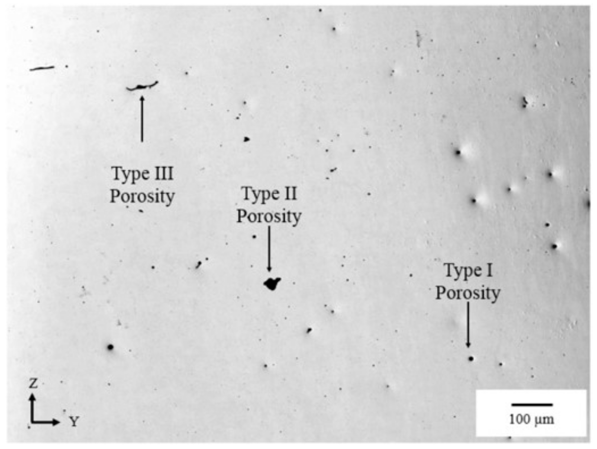
In the as-built and heat-treated specimens, many microscopic defects (porosity or inclusions) could exist due to non-optimal thermal histories impacting the wettability, thermal, and flow behavior of the melt pool. These porosities can be classified into three types by their characteristic morphology and different formation mechanism, as shown in Figure 11 [129]. Type I porosity is in a spherical shape caused by entrapped gases and low laser penetration depth due to the vapor pressure of the entrained gas. This may be affected by the powder packing density and the powder manufacturing process [26,133]. The shape of type II porosity is more irregular than that of a trapped gas pore occurring from a submicron to macro-size [34] It is caused by many factors related to the AM process, such as cracking caused by thermal stress, incomplete melting of particles, and balling by the inability of the melt pool to overcome surface tension, which creates incomplete coverage for the next powder layer [34]. Type III is mostly an irregular slit shape [26] leading to stress concentrations more severe than spherically shaped pores, caused by the incomplete fusion of the powder layer into the underlying layer, resulting in inter-laminar cracking or elongated voids along the boundary of molten pool [134]. Such voids have a significant impact on the mechanical properties of L-PBF parts, especially its elongation to failure and fatigue behavior, due to the susceptibility of crack initiation.
4. Mechanical Properties
4.1. Hardness Distribution
4.1.1. Effect of Process Parameters on Hardness
Ponnusamy [135] investigated the effect of defocus distance of the laser beam on the surface characteristics of 17–4 PH stainless-steel parts manufactured by L-PBF. The results showed that the maximum microhardness was about 414 HV with minimal surface roughness for samples with a defocus of -4 mm at 85% laser power (maximum power 300 W). The hardness of L-PBF parts obtained using water-atomized powder is considerably lower than that of gas-atomized and wrought alloy parts because of the higher content of martensite in gas-atomized powder. The hardness of L-PBF parts increases from 18 HRC to 24 HRC when the energy density increases from 64 J/mm3 to 104 J/mm3. This might be due to the relatively higher density of the parts being manufactured at higher laser energy density, as reported by Pasebani [93]. Irrinki [115] also found that hardness of parts fabricated through both water-atomized and gas-atomized powders increased with increased laser energy density. Murr et al. [96] compared the L-PBF fabrication of both Ar-atomized and N2-atomized powder in an Ar atmosphere (Ar/Ar; N2/Ar). It was found that L-PBF fabrication of N2-atomized powder in a N2 atmosphere (N2/N2) generated more retained austenite with lower hardness. Accordingly, Ar-atomized powder (Ar/N2) in N2 atmosphere produces a similar content of martensite (Ar/Ar; N2/Ar) to that of Ar and N2 powder in Ar atmosphere accompanied by similar hardness values, as shown in Figure 11 of Reference [96]. Building orientation, inter-layer time intervals, and energy density can affect the thermal history experienced during the fabrication, which results in a different amount of retained austenite in the microstructure, showing different microhardness. The correlations among scanning velocity, hatch spacing, slice thickness, and microhardness all exhibit a downward trend. The volume percentage and size of the Cu precipitates play an important role in changing the microhardness [131].
4.1.2. Effect of Heat Treatment on Hardness
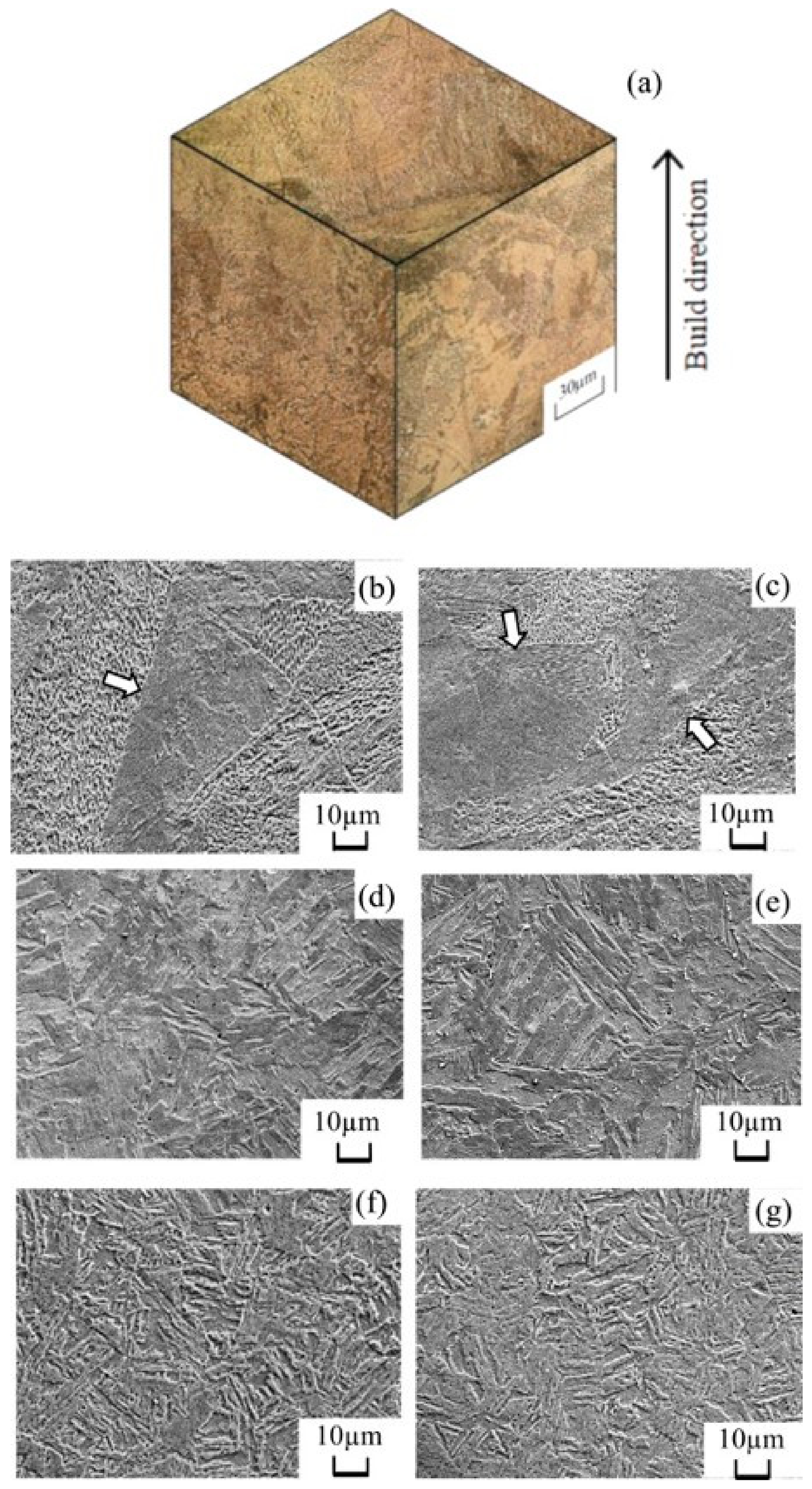
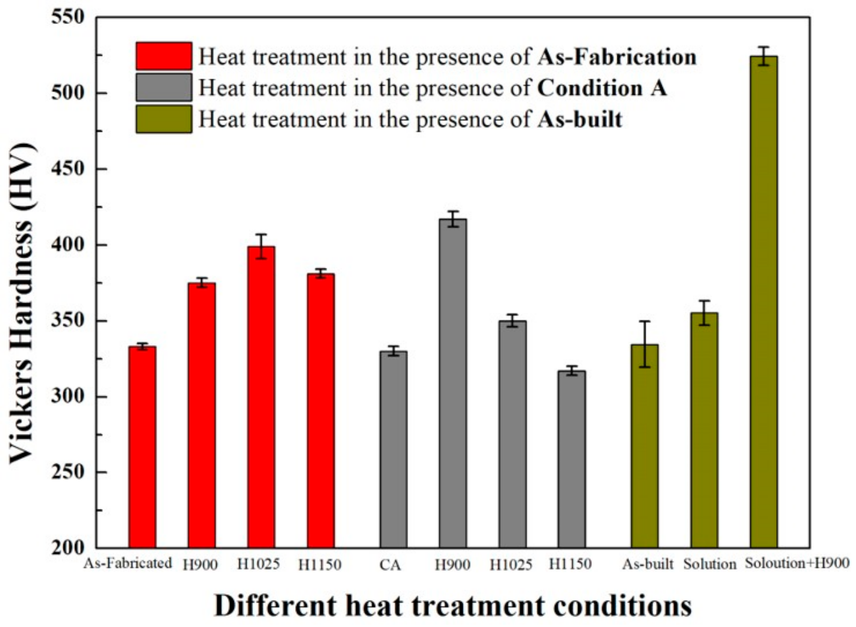
As reported by Akita et al. [17], the average hardness of as-built, L-PBF-quenched (the as-built sample was heated to 1050 °C and held for 4 h, followed by water quenching), and CM (conventionally melted) specimens were 275 HV, 340 HV, and 454 HV (test load: 4.9 N, load-holding time: 30s), respectively. The microstructure (Figure 12) containing δ-ferrite (soft-tough phase) was attributed to the relatively slow cooling rate during the L-PBF process, while the microstructures of the L-PBF-quenched specimen were more uniform. This specimen consists of rough acicular martensite due to the extremely fast cooling rate by water quenching. The martensite in the CM sample is finer and more uniform than the L-PBF-quenched sample. The above differences in microstructure explain the changes in hardness shown in Figure 13. Previous investigations of L-PBF 17–4 PH stainless steels focused on evaluating the heat treatment response of as-built material through hardness measurements in the solutionized [27,129,136,137], solutionized and aged [27,93,129,136], and aged only conditions [27,95,96], as shown in Table 6. The L-PBF + SHT specimen exhibited higher hardness values than the As-L-PBF sample. A higher martensitic phase fraction and some traces of Cu-rich precipitates in L-PBF + SHT specimen were responsible for the increase in hardness. The L-PBF + SHT + aging specimen exhibited much higher hardness than the L-PBF + SHT specimen. This increase was mainly due to precipitation strengthening by the aging process. When going from the as-built condition directly into an aging heat treatment (without solution treatment), the change in hardness values depends on the amount of retained austenite, which is dictated primarily by the original atomization condition of the powders [136].
4.2. Tensile Properties
L-PBF 17–4 PH SS parts are not necessarily fully martensitic and often contain some retained austenite. The amount of retained austenite can be highly dependent on various fabrication conditions. The volume percentage of retained austenite may significantly influence the material’s strength, toughness, strain hardening, and elongation to failure [95,96]. With the increase in the content of retained austenite phase, the tensile strength and hardness of the parts decrease, while the retained austenite is beneficial to improve the strain hardening and elongation at break because of the transformation-induced plasticity (TRIP) effect.
Studies [26,122] were conducted to investigate the effect of building orientation on mechanical properties, as shown in Table 7. The results showed that the building direction has a certain influence on the monotonic stretching behavior of L-PBF 17–4 PH stainless steel. Compared with the horizontal sample, the vertical sample has a small volume per unit volume and a large porosity. For vertical specimens, the weak interfacial layer is perpendicular to the direction of the tensile load, providing an easier route for pore growth and coalescence. However, in horizontal samples, these layers are parallel to the loading axis, which hinders the opening and expansion of the voids [26]. The increase in strength could be attributed to the relatively higher density of the manufactured part at a higher laser energy density, which produces sufficient heat to melt the powder, and the fraction of martensitic phase increased in the part made in water-atomized powder [93,125]. Furthermore, the strength of the as-built sample after heat treatment was improved to different extents both shown in Table 8. The effect of heat treatment on the strength (yield strength and tensile strength) is attributed to the hardened second-phase precipitates in the matrix, as well as other changes in microstructure characteristics, i.e., the phase volume fraction (relative volume fraction of martensite to retained austenite), grain size, and morphology. The martensite phase content of the L-PBF + SHT or Condition A (CA) sample is higher than that of the AS-L-PBF sample, which is responsible for the higher strength. After the aging process, the L-PBF + SHT + aging or CA- H××× specimen also has a higher strength due to precipitation of chromium-nickel-copper, which occurs during aging as shown in Table 8. The enhancement of L-PBF + direct aging comes from work hardening [122]. In addition, the voids, pores, and unmelted areas (i.e., weaker metallurgical bonding) between layers can be attributed to entrained gases and lower laser penetration depth. Such voids obviously affect the mechanical properties of materials, especially their elongation at break and fatigue properties.
4.3. Fatigue Properties
For L-PBF PH SS components, it is important to pay attention to their fatigue behavior. This is because fatigue failure is the most common failure mechanism in many engineering components and structures. Fatigue failure is the result of cyclic loading and may occur when the stress is much smaller than that caused by monotonic failure.
Few studies tested the performance of L-PBF fabricated 17–4 PH stainless-steel parts under cyclic loading, and the results indicated that fatigue properties were more sensitive to the defects generated by L-PBF (e.g., porosity, microcracks), leading to the low fracture strains and stresses under cyclic loading. Akita et al. [17] compared the fatigue strengths and crack growth behavior fabricated by L-PBF, L-PBF-quenched (the as-built sample was heated to 1050 °C and held for 4 h, followed by water quenching), and CM (conventionally melted) samples. The L-PBF and L-PBF-quenched 17–4 PH stainless steel exhibited much lower fatigue strengths compared to the CM one due to the lower hardness and higher population of defects. However, fatigue crack growth resistances of the L-PBF and L-PBF-quenched 17–4 PH stainless steel were higher than that of the CM one due to frequent crack branching and deflection. Yadollahi et al. [26] investigated the effects of building orientation and heat treatment (solution annealing and peak aging) on the fatigue properties. The voids and interlayer cavities formed by insufficient melting of vertical specimens in L-PBF process were more harmful than those of horizontal specimens. This is because they provide greater stress concentration under load, which results in lower fatigue strength, as shown in Figure 14. It was also found that the high cycle fatigue life of the specimens after heat treatment is significantly lower than that of the as-built parts, which is because the fatigue life is more sensitive to impurities precipitated during aging. In contrast, the low cycle fatigue life of the specimens is higher than that of the as-built parts. However, the results show that using Archimedes’ principle to measure the scalar density of a single piece is an ineffective method to improve the fatigue strength of a single piece. Future research directions should pay attention to how to adjust process parameters to improve fatigue performance with sufficient density.
5. Summary and Outlook
In this paper, previous studies on PH stainless steels parts fabricated by L-PBF were reviewed. The effects of initial powder characteristic, process parameters, and post-heat treatment on L-PBF microstructure, phase transformation behavior, and mechanical properties were discussed.
Despite the attractive advantages of producing PH stainless-steel parts by L-PBF, obstacles still remain, which hamper its widespread practical applications in industrial applications. Rapid melting, solidification, and re-melting of powders during the process and different combinations of processing parameters result in a complex thermal history and complicated microstructure. In the future, the influence of various factors, including process parameters, initial powder characteristic, building atmosphere, and post-heat treatments needs to be deeply studied to understand the phase transformation and microstructure evolutions which occur during the L-PBF of PH stainless steels. Accurately identifying δ-ferrite, ferrite, and martensite in L-PBFed PH stainless-steel samples is of significant importance for further studies on microstructure evolution. Fatigue properties and corrosion properties should be further investigated to realize the industrial applications of L-PBFed PH stainless steels. More investigations on the influence of various heat treatments on the microstructure evolution are necessary to better control the microstructures and properties of L-PBFed PH stainless steels through high-efficiency and low-cost heat treatments.
Author Contributions
Writing—original draft preparation, L.Z.; writing—outline of the paper, review, editing, supervision and funding acquisition, C.Z. (L.Z. and C.Z. contributed equally to this paper); writing—review and editing, Y.W., W.G., D.W., X.T., and Y.T. All authors have read and agreed to the published version of the manuscript.
Funding
This work was supported by the National Natural Science Foundation of China, grant number 51605287, and the Natural Science Foundation of Shanghai, grant number 16ZR1417100. This work was also supported by the fund of the State Key Laboratory of Long-Life High Temperature Materials (DTCC28EE190933). Yiqiang Wang would like to acknowledge EPSRC Grant EP/T012250/1.
Conflicts of Interest
The authors declare no conflicts of interest.
References
- Bahrami Balajaddeh, M.; Naffakh-Moosavy, H. Pulsed Nd:YAG laser welding of 17–4 PH stainless steel: Microstructure, mechanical properties, and weldability investigation. Opt. Laser Technol. 2019, 119, 105651. [Google Scholar] [CrossRef]
- Wang, D.; Chi, C.T.; Wang, W.Q.; Li, Y.L.; Wang, M.S.; Chen, X.G.; Chen, Z.H.; Cheng, X.P.; Xie, Y.J. The effects of fabrication atmosphere condition on the microstructural and mechanical properties of laser direct manufactured stainless steel 17–4 PH. J Mater. Sci. Technol. 2019, 35, 1315–1322. [Google Scholar] [CrossRef]
- Jan Kazior, A.S.-N.; Tadeusz, P.; Marek, H.; Marek, N. Properties of Precipitation Hardening 17–4 PH Stainless Steel Manufactured by Powder Metallurgy Technology. Adv. Mater. Res. 2013, 811, 87–92. [Google Scholar] [CrossRef]
- Wang, J.; Zou, H.; Li, C.; Qiu, S.; Shen, B. The spinodal decomposition in 17–4PH stainless steel subjected to long-term aging at 350 °C. Mater. Charact. 2008, 59, 587–591. [Google Scholar] [CrossRef]
- Murayama, M.; Hono, K.; Katayama, Y. Microstructural evolution in a 17–4 PH stainless steel after aging at 400 °C. Metall. Mater. Trans. A 1999, 30, 345–353. [Google Scholar] [CrossRef]
- Hsiao, C.-N.; Chiou, C.S.; Yang, J.-R. Aging reactions in a 17–4 PH stainless steel. Mater. Chem. Phys. 2002, 74, 134–142. [Google Scholar] [CrossRef]
- Viswanathan, U.K. Effects of Aging on the Microstructure of 17–4 PH Stainless Steel. Mater. Sci. Eng. A 1988, 104, 181–189. [Google Scholar] [CrossRef]
- Bayode, A.; Pityana, S.; Akinlabi, E.T.; Shongwe, M.B. Effect of scanning speed on laser deposited 17–4PH stainless steel. In Proceedings of the 2017 8th International Conference on Mechanical and Intelligent Manufacturing Technologies (ICMIMT), Cape Town, South Africa, 3–6 February 2017; IEEE: Piscataway, NJ, USA, 2017. [Google Scholar] [CrossRef]
- Deng, D.; Chen, R.; Sun, Q.; Li, X. Microstructural Study of 17–4PH Stainless Steel after Plasma-Transferred Arc Welding. Materials 2015, 8, 424–434. [Google Scholar] [CrossRef] [Green Version]
- Bhambroo, R.; Roychowdhury, S.; Kain, V.; Raja, V.S. Effect of reverted austenite on mechanical properties of precipitation hardenable 17–4 stainlesssteel. Mater. Sci. Eng. A 2013, 568, 127–133. [Google Scholar] [CrossRef]
- Chien, W.-T.; Tsai, C.-S. The investigation on the prediction of tool wear and the determination of optimum cutting conditions in machining 17–4PH stainless steel. J. Mater. Process. Technol. 2003, 140, 340–345. [Google Scholar] [CrossRef]
- Raj, S.V.; Ghosn, L.J.; Lerch, B.A.; Hebsur, M.; Cosgriff, L.M.; Fedor, J. Mechanical properties of 17–4PH stainless steel foam panels. Mater. Sci. Eng. A 2007, 456, 305–316. [Google Scholar] [CrossRef] [Green Version]
- Arisoy, C.F.; Başman, G.; Şeşen, M.K. Failure of a 17–4 PH stainless steel sailboat propeller shaft. Eng. Fail. Anal. 2003, 10, 711–717. [Google Scholar] [CrossRef]
- Bhaduri, A.K.; Gill, T.P.S.; Srinivasan, G.; Sujith, S. Optimised post-weld heat treatment procedures and heat input for welding 17–4PH stainless steel. Sci. Technology Weld. Join. 2013, 4, 295–301. [Google Scholar] [CrossRef]
- Lin, X.; Cao, Y.; Wu, X.; Yang, H.; Chen, J.; Huang, W. Microstructure and mechanical properties of laser forming repaired 17–4PH stainless steel. Mater. Sci. Eng. A 2012, 553, 80–88. [Google Scholar] [CrossRef]
- Jui-hung Wu, C.-k.L. Tensile and fatigue properties of 17–4 PH stainless steel at high temperatures. Metall. Mater. Trans. A 2002, 33, 1715–1724. [Google Scholar]
- Akita, M.; Uematsu, Y.; Kakiuchi, T.; Nakajima, M.; Kawaguchi, R. Defect-dominated fatigue behavior in type 630 stainless steel fabricated by selective laser melting. Mater. Sci. Eng. A 2016, 666, 19–26. [Google Scholar] [CrossRef]
- Pham, M.-S.; Dovgyy, B.; Hooper, P.A.; Gourlay, C.M.; Piglione, A. The role of side-branching in microstructure development in laser powder-bed fusion. Nat. Communications 2020, 11, 749. [Google Scholar] [CrossRef]
- Hou, H.; Simsek, E.; Ma, T.; Johnson, N.S.; Qian, S.; Cissé, C.; Stasak, D.; Hasan, N.A.; Zhou, L.; Hwang, Y.; et al. Fatigue-resistant high-performance elastocaloric materials made by additive manufacturing. Science 2019, 366, 1116–1121. [Google Scholar] [CrossRef] [Green Version]
- Todaro, C.J.; Easton, M.A.; Qiu, D.; Zhang, D.; Bermingham, M.J.; Lui, E.W.; Brandt, M.; StJohn, D.H.; Qian, M. Grain structure control during metal 3D printing by high-intensity ultrasound. Nat. Commun. 2020, 11, 142. [Google Scholar] [CrossRef]
- Martin, A.A.; Calta, N.P.; Khairallah, S.A.; Wang, J.; Depond, P.J.; Fong, A.Y.; Thampy, V.; Guss, G.M.; Kiss, A.M.; Stone, K.H.; et al. Dynamics of pore formation during laser powder bed fusion additive manufacturing. Nat. Commun. 2019, 10. [Google Scholar] [CrossRef] [Green Version]
- Lin, T.-C.; Cao, C.; Sokoluk, M.; Jiang, L.; Wang, X.; Schoenung, J.M.; Lavernia, E.J.; Li, X. Aluminum with dispersed nanoparticles by laser additive manufacturing. Nat. Commun. 2019, 10, 4124. [Google Scholar] [CrossRef] [PubMed] [Green Version]
- DebRoy, T.; Mukherjee, T.; Milewski, J.O.; Elmer, J.W.; Ribic, B.; Blecher, J.J.; Zhang, W. Scientific, technological and economic issues in metal printing and their solutions. Nat. Mater. 2019, 18, 1026–1032. [Google Scholar] [CrossRef] [PubMed]
- Martin, J.H.; Yahata, B.D.; Hundley, J.M.; Mayer, J.A.; Schaedler, T.A.; Pollock, T.M. 3D printing of high-strength aluminium alloys. Nature 2017, 549, 365–369. [Google Scholar] [CrossRef] [PubMed]
- Li, N.; Huang, S.; Zhang, G.; Qin, R.; Liu, W.; Xiong, H.; Shi, G.; Blackburn, J. Progress in additive manufacturing on new materials: A review. J Mater. Sci. Technol. 2019, 35, 242–269. [Google Scholar] [CrossRef]
- Yadollahi, A.; Shamsaei, N.; Thompson, S.M.; Elwany, A.; Bian, L. Effects of building orientation and heat treatment on fatigue behavior of selective laser melted 17–4 PH stainless steel. Int. J. Fatigue 2017, 94, 218–235. [Google Scholar] [CrossRef]
- LeBrun, T.; Nakamoto, T.; Horikawa, K.; Kobayashi, H. Effect of retained austenite on subsequent thermal processing and resultant mechanical properties of selective laser melted 17–4 PH stainless steel. Mater. Des. 2015, 81, 44–53. [Google Scholar] [CrossRef]
- Caballero, A.; Ding, J.; Ganguly, S.; Williams, S. Wire + Arc Additive Manufacture of 17–4 PH stainless steel: Effect of different processing conditions on microstructure, hardness, and tensile strength. J. Mater. Process. Technol. 2019, 268, 54–62. [Google Scholar] [CrossRef]
- Williams, S.W.; Martina, F.; Addison, A.C.; Ding, J.; Pardal, G.; Colegrove, P. Wire + Arc Additive Manufacturing. Mater. Sci. Technol. 2016, 32, 641–647. [Google Scholar] [CrossRef] [Green Version]
- Martina, F.; Ding, J.; Williams, S.; Caballero, A.; Pardal, G.; Quintino, L. Tandem metal inert gas process for high productivity wire arc additive manufacturing in stainless steel. Addit. Manuf. 2019, 25, 545–550. [Google Scholar] [CrossRef] [Green Version]
- Jin, W.; Zhang, C.; Jin, S.; Tian, Y.; Wellmann, D.; Liu, W. Wire arc additive manufacturing of stainless steels: a review. Appl. Sci. 2020. [Google Scholar]
- Gu, D.D.; Meiners, W.; Wissenbach, K.; Poprawe, R. Laser additive manufacturing of metallic components: materials, processes and mechanisms. Int. Mater. Rev. 2013, 57, 133–164. [Google Scholar] [CrossRef]
- Frazier, W.E. Metal Additive Manufacturing: A Review. J. Mater. Eng. Perform. 2014, 23, 1917–1928. [Google Scholar] [CrossRef]
- Sames, W.J.; List, F.A.; Pannala, S.; Dehoff, R.R.; Babu, S.S. The metallurgy and processing science of metal additive manufacturing. Int. Mater. Rev. 2016, 61, 315–360. [Google Scholar] [CrossRef]
- Wood, P.; Libura, T.; Kowalewski, L.Z.; Williams, G.; Serjouei, A. Influences of Horizontal and Vertical Build Orientations and Post-Fabrication Processes on the Fatigue Behavior of Stainless Steel 316L Produced by Selective Laser Melting. Materials 2019, 12. [Google Scholar] [CrossRef] [PubMed] [Green Version]
- Strakosova, A.; Kubásek, J.; Michalcová, A.; Průša, F.; Vojtěch, D.; Dvorský, D. High Strength X3NiCoMoTi 18-9-5 Maraging Steel Prepared by Selective Laser Melting from Atomized Powder. Materials 2019, 12. [Google Scholar] [CrossRef] [PubMed] [Green Version]
- El Kashouty, F.M.; Rennie, E.W.A.; Ghazy, M. Tool Life Performance of Injection Mould Tooling Fabricated by Selective Laser Melting for High-Volume Production. Materials 2019, 12. [Google Scholar] [CrossRef] [Green Version]
- Natali, S.; Brotzu, A.; Pilone, D. Comparison between Mechanical Properties and Structures of a Rolled and a 3D-Printed Stainless Steel. Materials 2019, 12. [Google Scholar] [CrossRef] [Green Version]
- Antunes, F.; Santos, L.; Capela, C.; Ferreira, J.; Costa, J.; Jesus, J.; Prates, P. Fatigue Crack Growth in Maraging Steel Obtained by Selective Laser Melting. Appl. Sciences 2019, 9. [Google Scholar] [CrossRef] [Green Version]
- Mugwagwa, L.; Yadroitsev, I.; Matope, S. Effect of Process Parameters on Residual Stresses, Distortions, and Porosity in Selective Laser Melting of Maraging Steel 300. Metals 2019, 9. [Google Scholar] [CrossRef] [Green Version]
- Abolhasani, D.; Seyedkashi, M.H.S.; Kang, N.; Kim, J.Y.; Woo, Y.Y.; Moon, H.Y. Analysis of Melt-Pool Behaviors during Selective Laser Melting of AISI 304 Stainless-Steel Composites. Metals 2019, 9. [Google Scholar] [CrossRef] [Green Version]
- Papula, S.; Song, M.; Pateras, A.; Chen, X.-B.; Brandt, M.; Easton, M.; Yagodzinskyy, Y.; Virkkunen, I.; Hänninen, H. Selective Laser Melting of Duplex Stainless Steel 2205: Effect of Post-Processing Heat Treatment on Microstructure, Mechanical Properties, and Corrosion Resistance. Materials 2019, 12. [Google Scholar] [CrossRef] [Green Version]
- Nguyen, D.-S.; Park, H.-S.; Lee, C.-M. Applying Selective Laser Melting to Join Al and Fe: An Investigation of Dissimilar Materials. Appl. Sci. 2019, 9. [Google Scholar] [CrossRef] [Green Version]
- Kwon, J.Y.; Casati, R.; Coduri, M.; Vedani, M.; Lee, S.C. Hydrogen Embrittlement Behavior of 18Ni 300 Maraging Steel Produced by Selective Laser Melting. Materials 2019, 12. [Google Scholar] [CrossRef] [PubMed] [Green Version]
- Esarte, J.; Blanco, M.J.; Bernardini, A.; Sancibrián, R. Performance Assessment of a Three-Dimensional Printed Porous Media Produced by Selective Laser Melting Technology for the Optimization of Loop Heat Pipe Wicks. Appl. Sci. 2019, 9. [Google Scholar] [CrossRef] [Green Version]
- Shi, W.; Wang, P.; Liu, Y.; Han, G. Experiment of Process Strategy of Selective Laser Melting Forming Metal Nonhorizontal Overhanging Structure. Metals 2019, 9. [Google Scholar] [CrossRef] [Green Version]
- Zhao, Z.; Li, J.; Bai, P.; Qu, H.; Liang, M.; Liao, H.; Wu, L.; Huo, P.; Liu, H.; Zhang, J. Microstructure and Mechanical Properties of TiC-Reinforced 316L Stainless Steel Composites Fabricated Using Selective Laser Melting. Metals 2019, 9, 267. [Google Scholar] [CrossRef] [Green Version]
- Yan, J.; Zhou, Y.; Gu, R.; Zhang, X.; Quach, W.-M.; Yan, M. A Comprehensive Study of Steel Powders (316L, H13, P20 and 18Ni300) for Their Selective Laser Melting Additive Manufacturing. Metals 2019, 9, 86. [Google Scholar] [CrossRef] [Green Version]
- Kurzynowski, T.; Stopyra, W.; Gruber, K.; Ziółkowski, G.; Kuźnicka, B.; Chlebus, E. Effect of Scanning and Support Strategies on Relative Density of SLM-ed H13 Steel in Relation to Specimen Size. Materials 2019, 12, 239. [Google Scholar] [CrossRef] [Green Version]
- Siddique, S.; Awd, M.; Wiegold, T.; Klinge, S.; Walther, F. Simulation of Cyclic Deformation Behavior of Selective Laser Melted and Hybrid-Manufactured Aluminum Alloys Using the Phase-Field Method. Appl. Sci. 2018, 8, 948. [Google Scholar] [CrossRef] [Green Version]
- Santos, M.S.L.; De Jesus, J.; Ferreira, M.J.; Costa, D.J.; Capela, C. Fracture Toughness of Hybrid Components with Selective Laser Melting 18Ni300 Steel Parts. Appl. Sci. 2018, 8, 879. [Google Scholar] [CrossRef] [Green Version]
- Chen, W.; Yin, G.; Feng, Z.; Liao, X. Effect of Powder Feedstock on Microstructure and Mechanical Properties of the 316L Stainless Steel Fabricated by Selective Laser Melting. Metals 2018, 8, 729. [Google Scholar] [CrossRef] [Green Version]
- Nguyen, L.V.; Kim, E.-a.; Lee, S.-R.; Yun, J.; Choe, J.; Yang, D.-y.; Lee, H.-s.; Lee, C.-w.; Yu, J.-H. Evaluation of Strain-Rate Sensitivity of Selective Laser Melted H13 Tool Steel Using Nanoindentation Tests. Metals 2018, 8, 589. [Google Scholar] [CrossRef] [Green Version]
- Luo, J.; Jia, X.; Gu, R.; Zhou, P.; Huang, Y.; Sun, J.; Yan, M. 316L Stainless Steel Manufactured by Selective Laser Melting and Its Biocompatibility with or without Hydroxyapatite Coating. Metals 2018, 8, 548. [Google Scholar] [CrossRef] [Green Version]
- Branco, R.; Costa, D.M.J.; Berto, F.; Razavi, M.S.; Ferreira, A.M.J.; Capela, C.; Santos, L.; Antunes, F. Low-Cycle Fatigue Behaviour of AISI 18Ni300 Maraging Steel Produced by Selective Laser Melting. Metals 2018, 8, 32. [Google Scholar] [CrossRef] [Green Version]
- Segura-Cardenas, E.; Ramirez-Cedillo, G.E.; Sandoval-Robles, A.J.; Ruiz-Huerta, L.; Caballero-Ruiz, A.; Siller, R.H. Permeability Study of Austenitic Stainless Steel Surfaces Produced by Selective Laser Melting. Metals 2017, 7, 521. [Google Scholar] [CrossRef] [Green Version]
- Hitzler, L.; Hirsch, J.; Heine, B.; Merkel, M.; Hall, W.; Öchsner, A. On the Anisotropic Mechanical Properties of Selective Laser-Melted Stainless Steel. Materials 2017, 10, 136. [Google Scholar] [CrossRef] [Green Version]
- Yusuf, M.S.; Chen, Y.; Boardman, R.; Yang, S.; Gao, N. Investigation on Porosity and Microhardness of 316L Stainless Steel Fabricated by Selective Laser Melting. Metals 2017, 7, 64. [Google Scholar] [CrossRef] [Green Version]
- Prashanth, G.K.; Löber, L.; Klauss, H.-J.; Kühn, U.; Eckert, J. Characterization of 316L Steel Cellular Dodecahedron Structures Produced by Selective Laser Melting. Technologies 2016, 4, 34. [Google Scholar] [CrossRef] [Green Version]
- Casati, R.; Lemke, N.J.; Tuissi, A.; Vedani, M. Aging Behaviour and Mechanical Performance of 18-Ni 300 Steel Processed by Selective Laser Melting. Metals 2016, 6, 218. [Google Scholar] [CrossRef]
- Boegelein, T.; Dryepondt, S.N.; Pandey, A.; Dawson, K.; Tatlock, G.J. Mechanical response and deformation mechanisms of ferritic oxide dispersion strengthened steel structures produced by selective laser melting. Acta Mater. 2015, 87, 201–215. [Google Scholar] [CrossRef] [Green Version]
- Guan, K.; Wang, Z.; Gao, M.; Li, X.; Zeng, X. Effects of processing parameters on tensile properties of selective laser melted 304 stainless steel. Mater. Des. 2013, 50, 581–586. [Google Scholar] [CrossRef]
- Nguyen, Q.B.; Zhu, Z.; Ng, F.L.; Chua, B.W.; Nai, S.M.L.; Wei, J. High mechanical strengths and ductility of stainless steel 304L fabricated using selective laser melting. J. Mater. Science Technol. 2019, 35, 388–394. [Google Scholar] [CrossRef]
- Tilita, G.A.; Chen, W.; Kwan, C.C.F.; Yuen, M.M.F. The effect of ultrasonic excitation on the microstructure of selective laser melted 304 L stainless steel. Mater. und Werkst. 2017, 48, 342–348. [Google Scholar] [CrossRef]
- Abd-Elghany, K.; Bourell, D.L. Property evaluation of 304L stainless steel fabricated by selective laser melting. Rapid Prototyp. J. 2012, 18, 420–428. [Google Scholar] [CrossRef]
- Kong, D.; Ni, X.; Dong, C.; Zhang, L.; Man, C.; Yao, J.; Xiao, K.; Li, X. Heat treatment effect on the microstructure and corrosion behavior of 316L stainless steel fabricated by selective laser melting for proton exchange membrane fuel cells. Electrochim. Acta 2018, 276, 293–303. [Google Scholar] [CrossRef]
- Ma, M.; Wang, Z.; Zeng, X. A comparison on metallurgical behaviors of 316L stainless steel by selective laser melting and laser cladding deposition. Mater. Sci. Eng. A 2017, 685, 265–273. [Google Scholar] [CrossRef]
- Ahmadi, A.; Mirzaeifar, R.; Moghaddam, N.S.; Turabi, A.S.; Karaca, H.E.; Elahinia, M. Effect of manufacturing parameters on mechanical properties of 316L stainless steel parts fabricated by selective laser melting: A computational framework. Mater. Des. 2016, 112, 328–338. [Google Scholar] [CrossRef]
- Zhang, B.; Dembinski, L.; Coddet, C. The study of the laser parameters and environment variables effect on mechanical properties of high compact parts elaborated by selective laser melting 316L powder. Mater. Sci. Eng. A 2013, 584, 21–31. [Google Scholar] [CrossRef]
- Suryawanshi, J.; Prashanth, K.G.; Ramamurty, U. Mechanical behavior of selective laser melted 316L stainless steel. Mater. Sci. Eng. A 2017, 696, 113–121. [Google Scholar] [CrossRef]
- Harun, W.S.W.; Asri, R.I.M.; Romlay, F.R.M.; Sharif, S.; Jan, N.H.M.; Tsumori, F. Surface characterisation and corrosion behaviour of oxide layer for SLMed-316L stainless steel. J. Alloy. Compd. 2018, 748, 1044–1052. [Google Scholar] [CrossRef]
- Casati, R.; Lemke, J.; Vedani, M. Microstructure and Fracture Behavior of 316L Austenitic Stainless Steel Produced by Selective Laser Melting. J. Mater. Sci. Technol. 2016, 32, 738–744. [Google Scholar] [CrossRef]
- Li, H.; Ramezani, M.; Li, M.; Ma, C.; Wang, J. Effect of process parameters on tribological performance of 316L stainless steel parts fabricated by selective laser melting. Manuf. Lett. 2018, 16, 36–39. [Google Scholar] [CrossRef]
- Bartolomeu, F.; Buciumeanu, M.; Pinto, E.; Alves, N.; Carvalho, O.; Silva, F.S.; Miranda, G. 316L stainless steel mechanical and tribological behavior—A comparison between selective laser melting, hot pressing and conventional casting. Addit. Manufacturing 2017, 16, 81–89. [Google Scholar] [CrossRef]
- Aggarwal, A.; Patel, S.; Kumar, A. Selective Laser Melting of 316L Stainless Steel: Physics of Melting Mode Transition and Its Influence on Microstructural and Mechanical Behavior. JOM 2018, 71, 1105–1116. [Google Scholar] [CrossRef]
- Alrbaey, K.; Wimpenny, D.; Tosi, R.; Manning, W.; Moroz, A. On Optimization of Surface Roughness of Selective Laser Melted Stainless Steel Parts: A Statistical Study. J. Mater. Eng. Perform. 2014, 23, 2139–2148. [Google Scholar] [CrossRef]
- Kong, D.; Ni, X.; Dong, C.; Lei, X.; Zhang, L.; Man, C.; Yao, J.; Cheng, X.; Li, X. Bio-functional and anti-corrosive 3D printing 316L stainless steel fabricated by selective laser melting. Mater. Des. 2018, 152, 88–101. [Google Scholar] [CrossRef]
- Kuznetsov, P.A.; Krasikov, A.V.; Staritsyn, M.V.; Mushnikova, S.Y.; Parmenova, O.N. Features of Local Corrosion of AISI316L Steel Manufactured by Selective Laser Melting. Prot. Met. Phys. Chem. Surf. 2018, 54, 484–489. [Google Scholar] [CrossRef]
- Mertens, A.; Reginster, S.; Paydas, H.; Contrepois, Q.; Dormal, T.; Lemaire, O.; Lecomte-Beckers, J. Mechanical properties of alloy Ti–6Al–4V and of stainless steel 316L processed by selective laser melting: influence of out-of-equilibrium microstructures. Powder Metall. 2014, 57, 184–189. [Google Scholar] [CrossRef]
- Shang, Y.; Yuan, Y.; Li, D.; Li, Y.; Chen, J. Effects of scanning speed on in vitro biocompatibility of 316L stainless steel parts elaborated by selective laser melting. Int. J. Adv. Manuf. Technol. 2017, 92, 4379–4385. [Google Scholar] [CrossRef]
- Badrossamay, M.; Childs, T.H.C. Further studies in selective laser melting of stainless and tool steel powders. Int. J. Mach. Tools Manufacture 2007, 47, 779–784. [Google Scholar] [CrossRef]
- Strano, G.; Hao, L.; Everson, R.M.; Evans, K.E. Surface roughness analysis, modelling and prediction in selective laser melting. J. Mater. Process. Technol. 2013, 213, 589–597. [Google Scholar] [CrossRef]
- Morgan, R.; Sutcliffe, C.J.; O’Neill, W. Density analysis of direct metal laser re-melted 316L stainless steel cubic primitives. J. Mater. Science 2004, 39, 1195–1205. [Google Scholar] [CrossRef]
- Riemer, A.; Leuders, S.; Thöne, M.; Richard, H.A.; Tröster, T.; Niendorf, T. On the fatigue crack growth behavior in 316L stainless steel manufactured by selective laser melting. Eng. Fracture Mech. 2014, 120, 15–25. [Google Scholar] [CrossRef]
- Tolosa, I.; Garciandía, F.; Zubiri, F.; Zapirain, F.; Esnaola, A. Study of mechanical properties of AISI 316 stainless steel processed by “selective laser melting”, following different manufacturing strategies. Int. J. Adv. Manuf. Technol. 2010, 51, 639–647. [Google Scholar] [CrossRef]
- Pinomaa, T.; Lindroos, M.; Walbrühl, M.; Provatas, N.; Laukkanen, A. The significance of spatial length scales and solute segregation in strengthening rapid solidification microstructures of 316L stainless steel. Acta Mater. 2020, 184, 1–16. [Google Scholar] [CrossRef]
- Hengsbach, F.; Koppa, P.; Duschik, K.; Holzweissig, M.J.; Burns, M.; Nellesen, J.; Tillmann, W.; Tröster, T.; Hoyer, K.-P.; Schaper, M. Duplex stainless steel fabricated by selective laser melting - Microstructural and mechanical properties. Mater. Des. 2017, 133, 136–142. [Google Scholar] [CrossRef]
- Saeidi, K.; Kevetkova, L.; Lofaj, F.; Shen, Z. Novel ferritic stainless steel formed by laser melting from duplex stainless steel powder with advanced mechanical properties and high ductility. Mater. Sci. Eng. A 2016, 665, 59–65. [Google Scholar] [CrossRef]
- Davidson, K.; Singamneni, S. Selective Laser Melting of Duplex Stainless Steel Powders: An Investigation. Mater. Manuf. Process. 2015, 31, 1543–1555. [Google Scholar] [CrossRef]
- Davidson, K.P.; Singamneni, S.B. Metallographic evaluation of duplex stainless steel powders processed by selective laser melting. Rapid Prototyp. J. 2017, 23, 1146–1163. [Google Scholar] [CrossRef]
- Vunnam, S.; Saboo, A.; Sudbrack, C.; Starr, T.L. Effect of powder chemical composition on the as-built microstructure of 17–4 PH stainless steel processed by selective laser melting. Addit. Manuf. 2019, 30, 100876. [Google Scholar] [CrossRef]
- Sun, Y.; Hebert, R.J.; Aindow, M. Non-metallic inclusions in 17–4PH stainless steel parts produced by selective laser melting. Mater. Des. 2018, 140, 153–162. [Google Scholar] [CrossRef]
- Pasebani, S.; Ghayoor, M.; Badwe, S.; Irrinki, H.; Atre, S.V. Effects of atomizing media and post processing on mechanical properties of 17–4 PH stainless steel manufactured via selective laser melting. Addit. Manuf. 2018, 22, 127–137. [Google Scholar] [CrossRef]
- Mahmoudi, M.; Elwany, A.; Yadollahi, A.; Thompson, S.M.; Bian, L.; Shamsaei, N. Mechanical properties and microstructural characterization of selective laser melted 17–4 PH stainless steel. Rapid Prototyp. J. 2017, 23, 280–294. [Google Scholar] [CrossRef] [Green Version]
- Rafi, H.K.; Pal, D.; Patil, N.; Starr, T.L.; Stucker, B.E. Microstructure and Mechanical Behavior of 17–4 Precipitation Hardenable Steel Processed by Selective Laser Melting. J. Mater. Eng. Perform. 2014, 23, 4421–4428. [Google Scholar] [CrossRef]
- Murr, L.E.; Martinez, E.; Hernandez, J.; Collins, S.; Amato, K.N.; Gaytan, S.M.; Shindo, P.W. Microstructures and Properties of 17–4 PH Stainless Steel Fabricated by Selective Laser Melting. J. Mater. Res. Technol. 2012, 1, 167–177. [Google Scholar] [CrossRef] [Green Version]
- Averyanova, M.; Cicala, E.; Bertrand, P.; Grevey, D. Experimental design approach to optimize selective laser melting of martensitic 17–4 PH powder: part I-single laser tracks and first layer. Rapid Prototyp. J. 2012, 18, 28–37. [Google Scholar] [CrossRef]
- Facchini, L.; Vicente, N.; Lonardelli, I.; Magalini, E.; Robotti, P.; Molinari, A. Metastable Austenite in 17–4 Precipitation-Hardening Stainless Steel Produced by Selective Laser Melting. Adv. Eng. Mater. 2010, 12, 184–188. [Google Scholar] [CrossRef]
- Qiu, C.; Kindi, M.A.; Aladawi, A.S.; Hatmi, I.A. A comprehensive study on microstructure and tensile behaviour of a selectively laser melted stainless steel. Scientific reports 2018, 8, 7785. [Google Scholar] [CrossRef]
- Tian, Z.; Zhang, C.; Wang, D.; Liu, W.; Fang, X.; Wellmann, D.; Zhao, Y.; Tian, Y. A Review on Laser Powder Bed Fusion of Inconel 625 Nickel-Based Alloy. Appl. Sci. 2019, 10, 81. [Google Scholar] [CrossRef] [Green Version]
- Chen, H.; Zhang, C.; Jia, D.; Wellmann, D.; Liu, W. Corrosion Behaviors of Selective Laser Melted Aluminum Alloys: A Review. Metals 2020, 10, 102. [Google Scholar] [CrossRef] [Green Version]
- Sun, Z.; Tan, X.; Tor, S.B.; Yeong, W.Y. Selective laser melting of stainless steel 316L with low porosity and high build rates. Mater. Des. 2016, 104, 197–204. [Google Scholar] [CrossRef]
- Li, X.P.; Van Humbeeck, J.; Kruth, J.P. Selective laser melting of weak-textured commercially pure titanium with high strength and ductility: A study from laser power perspective. Mater. Des. 2017, 116, 352–358. [Google Scholar] [CrossRef]
- Wang, D.; Yang, Y.; Yi, Z.; Su, X. Research on the fabricating quality optimization of the overhanging surface in SLM process. Int. J. Adv. Manuf. Technol. 2012, 65, 1471–1484. [Google Scholar] [CrossRef]
- Yadroitsev, I.; Smurov, I. Selective laser melting technology: From the single laser melted track stability to 3D parts of complex shape. Phys. Procedia 2010, 5, 551–560. [Google Scholar] [CrossRef] [Green Version]
- Hanzl, P.; Zetek, M.; Bakša, T.; Kroupa, T. The Influence of Processing Parameters on the Mechanical Properties of SLM Parts. Procedia Eng. 2015, 100, 1405–1413. [Google Scholar] [CrossRef] [Green Version]
- Zhou, B.; Zhou, J.; Li, H.; Lin, F. A study of the microstructures and mechanical properties of Ti6Al4V fabricated by SLM under vacuum. Mater. Sci. Eng. A 2018, 724, 1–10. [Google Scholar] [CrossRef]
- Hunt, J.; Derguti, F.; Todd, I. Selection of steels suitable for additive layer manufacturing. Ironmak. Steelmak. 2014, 41, 254–256. [Google Scholar] [CrossRef]
- Xiebin Wang, S.K.; Van Humbeeck, J. A Short Review on the Microstructure, Transformation Behavior and Functional Properties of NiTi Shape Memory Alloys Fabricated by Selective Laser Melting. Materials 2018, 11, 1683. [Google Scholar] [CrossRef] [Green Version]
- Qi, L.-h.; Chao, Y.-p.; Luo, J.; Zhou, J.-m.; Hou, X.-h.; Li, H.-j. A novel selection method of scanning step for fabricating metal components based on micro-droplet deposition manufacture. Int. J. Mach. Tools Manuf. 2012, 56, 50–58. [Google Scholar] [CrossRef]
- Pinkerton, A.J. [INVITED] Lasers in additive manufacturing. Opt. Laser Technol. 2016, 78, 25–32. [Google Scholar] [CrossRef] [Green Version]
- Santos, E.C.; Shiomi, M.; Osakada, K.; Laoui, T. Rapid manufacturing of metal components by laser forming. Int. J. Mach. Tools Manuf. 2006, 46, 1459–1468. [Google Scholar] [CrossRef]
- Zinovieva, O.; Zinoviev, A.; Ploshikhin, V. Three-dimensional modeling of the microstructure evolution during metal additive manufacturing. Comput. Mater. Sci. 2018, 141, 207–220. [Google Scholar] [CrossRef]
- Körner, C. Additive manufacturing of metallic components by selective electron beam melting — a review. Int. Mater. Rev. 2016, 61, 361–377. [Google Scholar] [CrossRef] [Green Version]
- Irrinki, H.; Dexter, M.; Barmore, B.; Enneti, R.; Pasebani, S.; Badwe, S.; Stitzel, J.; Malhotra, R.; Atre, S.V. Effects of Powder Attributes and Laser Powder Bed Fusion (L-PBF) Process Conditions on the Densification and Mechanical Properties of 17–4 PH Stainless Steel. JOM 2016, 68, 860–868. [Google Scholar] [CrossRef]
- Gu, H.G.H.; Pal, D.; Rafi, K.; Starr, T.; Stucker, B. Influences of Energy Density on Porosity and Microstructure of Selective Laser Melted 17–4 PH Stainless Steel. Solid Free. Fabr. Symp. 2013, 474–489. [Google Scholar]
- Alnajjar, M.; Christien, F.; Wolski, K.; Bosch, C. Evidence of austenite by-passing in a stainless steel obtained from laser melting additive manufacturing. Addit. Manuf. 2019, 25, 187–195. [Google Scholar] [CrossRef]
- Ouyang, D.; Li, N.; Xing, W.; Zhang, J.; Liu, L. 3D printing of crack-free high strength Zr-based bulk metallic glass composite by selective laser melting. Intermetallics 2017, 90, 128–134. [Google Scholar] [CrossRef]
- Lebrun, T.; Tanigaki, K.; Horikawa, K.; Kobayashi, H. Strain rate sensitivity and mechanical anisotropy of selective laser melted 17–4 PH stainless steel. Mech. Eng. J. 2014, 1, SMM0049. [Google Scholar] [CrossRef] [Green Version]
- Jerrard, P.G.E.; Hao, L.; Evans, K.E. Experimental investigation into selective laser melting of austenitic and martensitic stainless steel powder mixtures. Proc. Inst. Mech. Eng. Part B J. Eng. Manuf. 2009, 223, 1409–1416. [Google Scholar] [CrossRef]
- Kokosza, A.; Pacyna, J. Evaluation of retained austenite stability in heat treated cold work tool steel. J. Mater. Process. Technol. 2005, 162–163, 327–331. [Google Scholar] [CrossRef]
- Hsu, T.-H.; Chang, Y.-J.; Huang, C.-Y.; Yen, H.-W.; Chen, C.-P.; Jen, K.-K.; Yeh, A.-C. Microstructure and property of a selective laser melting process induced oxide dispersion strengthened 17–4 PH stainless steel. J. Alloy Compd. 2019, 803, 30–41. [Google Scholar] [CrossRef]
- Sun, Y.; Hebert, R.J.; Aindow, M. Effect of heat treatments on microstructural evolution of additively manufactured and wrought 17–4PH stainless steel. Mater. Des. 2018, 156, 429–440. [Google Scholar] [CrossRef]
- Wu, J.; Wray, P.J.; Garcia, C.I.; Hua, M.; Deardo, A.J. Image Quality Analysis: A New Method of Characterizing Microstructures. ISIJ Int. 2005, 45, 254–262. [Google Scholar] [CrossRef] [Green Version]
- Irrinki, H.; Jangam, J.S.D.; Pasebani, S.; Badwe, S.; Stitzel, J.; Kate, K.; Gulsoy, O.; Atre, S.V. Effects of particle characteristics on the microstructure and mechanical properties of 17–4 PH stainless steel fabricated by laser-powder bed fusion. Powder Technol. 2018, 331, 192–203. [Google Scholar] [CrossRef]
- Hoeges, S.; Zwiren, A.; Schade, C. Additive manufacturing using water atomized steel powders. Met. Powder Rep. 2017, 72, 111–117. [Google Scholar] [CrossRef]
- Cheruvathur, S.; Lass, E.A.; Campbell, C.E. Additive Manufacturing of 17–4 PH Stainless Steel: Post-processing Heat Treatment to Achieve Uniform Reproducible Microstructure. JOM 2015, 68, 930–942. [Google Scholar] [CrossRef]
- Yadollahi, A.; Shamsaei, N.; Thompson, S.M.; Seely, D.W. Effects of process time interval and heat treatment on the mechanical and microstructural properties of direct laser deposited 316L stainless steel. Mater. Sci. Eng. A 2015, 644, 171–183. [Google Scholar] [CrossRef]
- Kudzal, A.; McWilliams, B.; Hofmeister, C.; Kellogg, F.; Yu, J.; Taggart-Scarff, J.; Liang, J. Effect of scan pattern on the microstructure and mechanical properties of Powder Bed Fusion additive manufactured 17–4 stainless steel. Mater. Des. 2017, 133, 205–215. [Google Scholar] [CrossRef]
- Krantz, M.; Zhang, H.; Zhu, J. Characterization of powder flow: Static and dynamic testing. Powder Technol. 2009, 194, 239–245. [Google Scholar] [CrossRef]
- Hu, Z.; Zhu, H.; Zhang, H.; Zeng, X. Experimental investigation on selective laser melting of 17–4PH stainless steel. Opt. Laser Technol. 2017, 87, 17–25. [Google Scholar] [CrossRef]
- Li, R.; Shi, Y.; Wang, Z.; Wang, L.; Liu, J.; Jiang, W. Densification behavior of gas and water atomized 316L stainless steel powder during selective laser melting. Appl. Surf. Sci. 2010, 256, 4350–4356. [Google Scholar] [CrossRef]
- Zhao, X.; Chen, J.; Lin, X.; Huang, W. Study on microstructure and mechanical properties of laser rapid forming Inconel 718. Mater. Sci. Eng. A 2008, 478, 119–124. [Google Scholar] [CrossRef]
- King, W.E.; Barth, H.D.; Castillo, V.M.; Gallegos, G.F.; Gibbs, J.W.; Hahn, D.E.; Kamath, C.; Rubenchik, A.M. Observation of keyhole-mode laser melting in laser powder-bed fusion additive manufacturing. J. Mater. Process. Technol. 2014, 214, 2915–2925. [Google Scholar] [CrossRef]
- Ponnusamy, P.; Masood, S.H.; Palanisamy, S.; Rahman Rashid, R.A.; Ruan, D. Characterization of 17–4PH alloy processed by selective laser melting. Mater. Today Proc. 2017, 4, 8498–8506. [Google Scholar] [CrossRef]
- Meredith, S.D.; Zuback, J.S.; Keist, J.S.; Palmer, T.A. Impact of composition on the heat treatment response of additively manufactured 17–4 PH grade stainless steel. Mater. Sci. Eng. A 2018, 738, 44–56. [Google Scholar] [CrossRef]
- Stoudt, M.R.; Ricker, R.E.; Lass, E.A.; Levine, L.E. The Influence of Post-Build Microstructure on the Electrochemical Behavior of Additively Manufactured 17–4 PH Stainless Steel. JOM 2017, 69, 506–515. [Google Scholar] [CrossRef] [Green Version]
Figure 1.
(a) Schematic of laser powder bed fusion (L-PBF) process, (b) gas-atomized (argon) 17–4 precipitation-hardened (PH) stainless steel (SS) powder; (c) vertically and (d) horizontally orientated cylindrical bars of 17–4 PH SS samples [26].
Figure 1.
(a) Schematic of laser powder bed fusion (L-PBF) process, (b) gas-atomized (argon) 17–4 precipitation-hardened (PH) stainless steel (SS) powder; (c) vertically and (d) horizontally orientated cylindrical bars of 17–4 PH SS samples [26].

Figure 2.
(a) XRD spectra and (c) EBSD orientation map (Inverse pole figure, IPF Z) of as-built 17–4 PH steel in the (Y–Z) plane parallel to the build direction; (b) XRD spectra and (d) EBSD orientation map (IPF Z) of as-built 17–4 PH steel in the (X–Y) plane perpendicular to the build direction [117].

Figure 3.
(a) XRD spectra of the as-built and heat-treated 17–4 PH SS samples, (b) as-received wrought sample, and (c) as-built sample; (d) a typical melt pool in the as-built sample. (e) An EBSD grain orientation map obtained from the area shown in Figure 3d [123].

Figure 4.
EBSD orientation maps: (a,b) as-built sample; (c) solution heat-treated (HT) sample; (d) H900 sample [123], 17–4 steel.
Figure 4.
EBSD orientation maps: (a,b) as-built sample; (c) solution heat-treated (HT) sample; (d) H900 sample [123], 17–4 steel.

Figure 5.
Micromorphology of 17–4 PH SS powder: (a) gas-atomized powder and (b) water-atomized powder [125]. (reproduced from [125], with permission from Elsevier, 2018).

Figure 6.
Optical micrographs of as built 17–4 PH SS perpendicular to the build direction: (a) gas-atomized at 64 J/mm3, (b) gas-atomized at 104 J/mm3, (c) water-atomized at 64 J/mm3, and (d) water-atomized at 104 J/mm3 [93].
Figure 6.
Optical micrographs of as built 17–4 PH SS perpendicular to the build direction: (a) gas-atomized at 64 J/mm3, (b) gas-atomized at 104 J/mm3, (c) water-atomized at 64 J/mm3, and (d) water-atomized at 104 J/mm3 [93].

Figure 7.
EBSD maps of selected areas in the middle region of (a) vertical and (b) horizontal as-built (AB) samples [26], material: 17–4 steel.
Figure 7.
EBSD maps of selected areas in the middle region of (a) vertical and (b) horizontal as-built (AB) samples [26], material: 17–4 steel.

Figure 8.
Schematic diagram of different scanning strategies [129].
Figure 8.
Schematic diagram of different scanning strategies [129].

Figure 9.
Volume fraction of austenite under different heat treatment conditions, material: 17–4 steel [27,122].

Figure 10.
Reverted austenite in L-PBF þ Direct Aging 17–4 PH specimens: (a) TEM image providing an overview of the reverted austenite; (b) selected area diffraction pattern (SADP) indicating reverted austenite (g phase); (c) SEM transmission Kikuchi diffraction (SEM-TKD) analyses showing the electron band contrast (BC), phase map of martensite (blue) and austenite (red), the inverse pole figure Z of martensite (IPFZ-bcc), and the inverse pole figure-Z of austenite (IPFZ-fcc) [122].

Figure 11.
Optical micrographs of 90-BF-F AM show typical defects observed in all samples (material: 17–4 steel). The loading direction is perpendicular to the page, and the building direction is parallel to the Z-direction [129].
Figure 11.
Optical micrographs of 90-BF-F AM show typical defects observed in all samples (material: 17–4 steel). The loading direction is perpendicular to the page, and the building direction is parallel to the Z-direction [129].

Figure 12.
(a) Three-dimensional macro-morphology of L-PBF specimen; (b,c) microstructure of L-PBF specimen; (d,e) microstructure of L-PBF-quenched specimen; (f,g) microstructure of conventionally melted (CM) specimen. (Material: 17–4 steel) Arrows indicate ferrite-rich area [17].
Figure 12.
(a) Three-dimensional macro-morphology of L-PBF specimen; (b,c) microstructure of L-PBF specimen; (d,e) microstructure of L-PBF-quenched specimen; (f,g) microstructure of conventionally melted (CM) specimen. (Material: 17–4 steel) Arrows indicate ferrite-rich area [17].


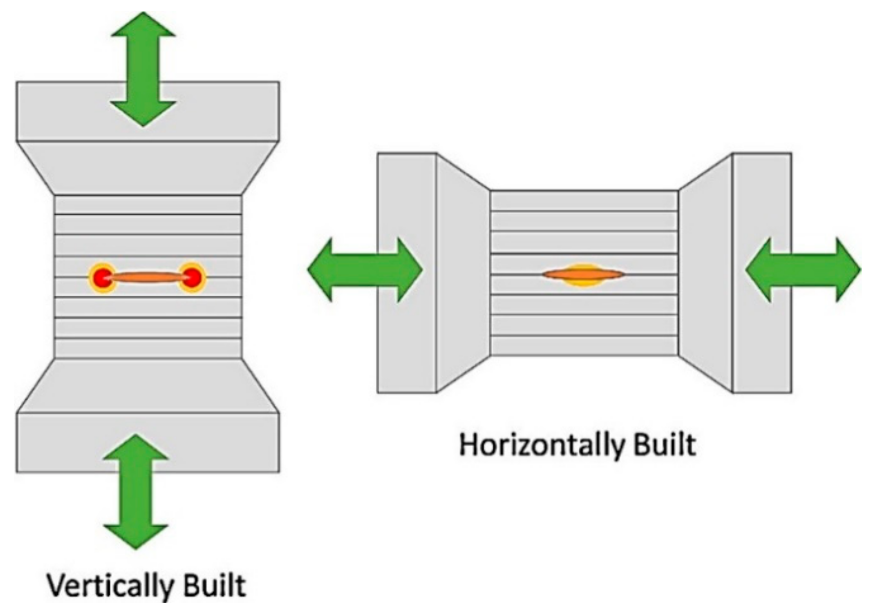
Figure 14.
Schematic diagram of the unmelted region formed in the vertical and horizontal building directions with respect to the direction of load and stress concentration [26].
Figure 14.
Schematic diagram of the unmelted region formed in the vertical and horizontal building directions with respect to the direction of load and stress concentration [26].


Table 1.
The effect of atomized media and building atmosphere on the amount of retained austenite.
| Powder Type | Argon Gas Fabrication | Nitrogen Gas Fabrication | Reference |
|---|---|---|---|
| Argon-atomized (α) | α 1 | α | [96] |
| Nitrogen-atomized α (6%) + γ (94%) | α | α (15%) + γ (85%) | [96] |
| Nitrogen-atomized (α + γ) | α (92%) + γ (8%) | α + γ (more than 50%) | [95] |
| Nitrogen-atomized α (dominate) + γ | α | - | [93] |
| Water-atomized α + γ (dominate) | α + γ 1 | - | [93] |
| Gas-atomized | α | - | [94] |
| Gas-atomized α (70%) + γ (30%) | α | - | [125] |
| Water-atomized α (20%) + γ (80%) | α (more than 20%) + γ | - | [125] |
1 α-(bcc-martensite); γ-(fcc-austenite); material: 17–4 steel.
Table 2.
The effect of energy destiny on the amount of retained austenite of parts obtained by gas-atomized and water-atomized powder (material: 17–4 steel).
Table 2.
The effect of energy destiny on the amount of retained austenite of parts obtained by gas-atomized and water-atomized powder (material: 17–4 steel).
| Energy Density(J/mm3) | Gas-Atomized Powder | Water-Atomized Powder | Chamber Atmosphere | Reference |
|---|---|---|---|---|
| 64 | α (coarse) | α + γ | Argon | [93] |
| 104 | α (fine) | α (fraction of phase increased) + γ | Argon | [93] |
| 64 | α | α (70 ± 5%) + γ (30 ± 5%) | Argon | [125] |
| 80 | α | α (75 ± 5%) + γ (25 ± 5%) | Argon | [125] |
| 84 | α | α (80 ± 5%) + γ (20 ± 5%) | Argon | [125] |
| 104 | α | α (90 ± 5%) + γ (10 ± 5%) | Argon | [125] |
Table 3.
The effect of scanning strategy on the average amount of austenite phase, 17–4 steel.
| Scanning Strategies | Average Austenite (Volume fraction, %) | Reference |
|---|---|---|
| 17–4 PH powder | 62.9 | [129] |
| Hexagon pattern 1 | ~58.3 | |
| Concentric middle 2 | ~82.4 | |
| Concentric edges 2 | ~50.3 | |
| 90-BF-F 3 | ~27.2 | |
| 90-BF-T 4 | ~25.2 | |
| 0-BF-F 5 | ~43.6 | |
| 0-BF-T 6 | ~69.9 |
1 The hexagon pattern (“hexagon”) consists of 25-mm-diameter hexagonal islands with a 100-μm overlap of hexagons within the layer. The hexagons are fused at a 45° angle to the loading axis of the tensile specimens. From layer to layer, in the Z-direction, the pattern angle alternates between 315° and 225°. The hexagon pattern is the default scan strategy for three-dimensional (3D) system metal printers. 2 Concentric pattern (“concentric”) consists of successive outlines of the part. In this case, the outer perimeter of the part is processed by the laser first, and the outlines move successively inward toward the center of the part. 3 90° vertical hatch pattern one direction (90-BF-F). This pattern is unidirectional in the axis perpendicular to the loading axis of the tensile bar. 4 90/270° vertical hatch pattern (90-BF-T). This pattern is bidirectional to the axis perpendicular to the loading axis of the tensile bar. 5 0° horizontal hatch pattern (0-BF-F). This pattern is unidirectional to the axis parallel to the loading axis of the tensile bar. 6 0/180° horizontal hatch pattern (0-BF-T). This pattern is bidirectional to the axis parallel to the loading axis of the tensile bar.
Table 4.
The effect of heat treatment conditions on the amount of austenite (material: 17–4 steel).
| Condition | Martensite (bcc, α), % | Austenite (fcc, γ), % | Reference |
|---|---|---|---|
| As-fabricated | 64.0 | 36.0 | [27] |
| H900 1 | 59.5 | 40.5 | [27] |
| H1025 | 89.6 | 10.4 | [27] |
| H1150 | 94.4 | 5.6 | [27] |
| Condition A 2 | 100 | 0 | [27] |
| CA-H900 | 96.7 | 3.3 | [27] |
| CA-H1025 | 95.3 | 4.7 | [27] |
| CA-H1150 | 79.6 | 20.4 | [27] |
| As-L-PBF | 93.8 | 6.2 | [122] |
| L-PBF + SHT 3 | 98.5 | 1.5 | [122] |
| L-PBF + SHT + Aging 4 | 95 | 5 | [122] |
| L-PBF + Direct Aging | 82.1 | 17.9 | [122] |
1 H900 (480 °C for 1 h), H1025 (550 °C for 4 h), and H1150 (620 °C for 4 h) heat treatments; 2 Condition A (CA) state (1040 °C for 30 min) and quenched prior to the subsequent aging; 3 SHT (solution heat treatment) was conducted at 788 °C for 2 h followed by water quenching to room temperature; 4 Aging was conducted at 482 °C for 1 h followed by water quenching to room temperature.
Table 5.
The effect of energy density and scanning strategy on the density of L-PBF parts (material: 17–4 steel).
Table 5.
The effect of energy density and scanning strategy on the density of L-PBF parts (material: 17–4 steel).
| L-PBF Parts from | Scanning Strategy | Energy Density (J/mm3) | Density (%) | Reference |
|---|---|---|---|---|
| Gas-atomized powder D50 = 13 μm Water-atomized powder D50 = 17 μm Water-atomized powder D50 = 24 μm Water-atomized powder D50 = 43 μm | N/A | 64 | 96.6 ± 0.5/96 ± 0.8/ 87 ± 0.3/89.7 ± 0.3 | [125] |
| N/A | 80 | 97.4 ± 0.5/97.1 ± 0.6/ 91.4 ± 0.6/94.5 ± 0.7 | [125] | |
| N/A | 84 | 97.6 ± 0.5/97 ± 0.8/ 96.3 ± 0.5/97 ± 0.5 | [125] | |
| N/A | 104 | 97.5 ± 0.5/97 ± 0.5/ 96.8 ± 0.1/97 ± 0.5 | [125] | |
| Average particle size 14.5 μm, D10 = 3.28 μm, D90 = 30.14 μm | Hexagon | 62.5 | 98.9 | [129] |
| Concentric | 62.5 | 98.2 | [129] | |
| 90-BF-F | 62.5 | 98.5 | [129] | |
| 90-BF-T | 62.5 | 98.8 | [129] | |
| 0-BF-F | 62.5 | 98.7 | [129] | |
| 0-BF-T | 62.5 | 98.7 | [129] |
Table 6.
The effect of heat treatment conditions on hardness (material: 17–4 steel).
| Condition | Hardness (HV) | Martensite (bcc, α), % | Austenite (fcc, γ), % | Reference |
|---|---|---|---|---|
| As-fabricated | 333 ± 2 | 64.0 | 36.0 | [27] |
| H900 1 | 375 ± 3 | 59.5 | 40.5 | [27] |
| H1025 | 399 ± 8 | 89.6 | 10.4 | [27] |
| H1150 | 381 ± 3 | 94.4 | 5.6 | [27] |
| Condition A 2 | 330 ± 3 | 100 | 0 | [27] |
| CA-H900 | 417 ± 5 | 96.7 | 3.3 | [27] |
| CA-H1025 | 350 ± 4 | 95.3 | 4.7 | [27] |
| CA-H1150 | 317 ± 3 | 79.6 | 20.4 | [27] |
| As-built | 334.5 ± 15 | N/A | N/A | [123] |
| Solution | 355.2 ± 8 | N/A | N/A | [123] |
| Solution + H900 | 524.5 ± 6 | N/A | N/A | [123] |
1 H900 (480 °C for 1 h), H1025 (550 °C for 4 h), and H1150 (620 °C for 4 h) heat treatments; 2 Condition A (CA) state (1040 °C for 30 min) and quenched prior to the subsequent aging.
Table 7.
The effect of build orientation on the mechanical properties (material: 17–4 steel).
| Samples | Yield Strength (MPa) | Ultimate Tensile Strength (MPa) | Elongation (%) | Reference | |
|---|---|---|---|---|---|
| As-built samples | Vertical | 580 | 940 | 5.8 | [26] |
| Horizontal | 650 | 1060 | 14.5 | ||
| CA-H900 samples | Vertical | 1020 | 1150 | 2.8 | |
| Horizontal | 1250 | 1410 | 11 | ||
Table 8.
The effect of heat treatments on the mechanical properties (material: 17–4 steel).
| Condition | Yield Strength (MPa) | Ultimate Tensile Strength (MPa) | Elongation (%) | Reference | |
|---|---|---|---|---|---|
| As-built samples, vertical | 580 | 940 | 5.8 | [26] | |
| CA-H900 samples, vertical | 1020 | 1150 | 2.8 | [26] | |
| As-built samples, horizontal | 650 | 1060 | 14.5 | [26] | |
| CA-H900 samples, horizontal | 1250 | 1410 | 11 | [26] | |
| As-fabricated | 661 ± 24 | 1255 ± 3 | 16.2 ± 2.5 | [27] | |
| H900 1 | 945 ± 12 | 1417 ± 6 | 15.5 ± 1.3 | [27] | |
| H1025 | 870 ± 25 | 1358 ± 8 | 13.3 ± 1.5 | [27] | |
| H1150 | 1005 ± 15 | 1319 ± 2 | 11.1 ± 0.4 | [27] | |
| Condition A 2 | 939 ± 9 | 1188 ± 6 | 9.0 ± 1.5 | [27] | |
| CA-H900 | 1352 ± 18 | 1444 ± 2 | 4.6 ± 0.4 | [27] | |
| CA-H1025 | 1121 ± 9 | 1172 ± 2 | 9.6 ± 1.7 | [27] | |
| CA-H1150 | 859 ± 11 | 1017 ± 15 | 16.6 ± 1.2 | [27] | |
| As-L-PBFed | 803 | 1228 | 12.7 | [122] | |
| L-PBF + SHT 3 | 966 | 1268 | 8.8 | [122] | |
| L-PBF + SHT + Aging 4 | 1276 | 1381 | 13.6 | [122] | |
| L-PBF + Direct Aging | 1173 | 1478 | 9.8 | [122] | |
| Solutionized at 1015 °C and aged at 482 °C | Gas-atomized (energy density y1 = 64 J/mm3, y2 = 104 J /mm3 | 1116/1200 | 1358/1368 | 5.2/2.6 | [93] |
| Water-atomized (energy density y1 = 64 J/mm3, y2 = 104 J/mm3 | 365/500 | 510/990 | 1/3.3 | [93] | |
| Solutionized at 1315 °C and aged at 482 °C | Gas-atomized (energy density y1 = 64 J/mm3, y2 = 104 J /mm3 | 1186/1255 | 1308/1300 | 2.6/2 | [93] |
| Water-atomized (energy density y1 = 64 J/mm3, y2 = 104 J/mm3 | 650/1000 | 780/1261 | 0.7/5.5 | [93] | |
1 H900 (480 °C for 1 h), H1025 (550 °C for 4 h), and H1150 (620 °C for 4 h) heat treatments; 2 Condition A (CA) state (1040 °C for 30 min) and quenched prior to the subsequent aging; 3 SHT (solution heat treatment) was conducted at 788 °C for 2 h, followed by water quenching to room temperature; 4 Aging was conducted at 482 °C for 1 h, followed by water quenching to room temperature.
© 2020 by the authors. Licensee MDPI, Basel, Switzerland. This article is an open access article distributed under the terms and conditions of the Creative Commons Attribution (CC BY) license (http://creativecommons.org/licenses/by/4.0/).
Share and Cite
MDPI and ACS Style
Zai, L.; Zhang, C.; Wang, Y.; Guo, W.; Wellmann, D.; Tong, X.; Tian, Y. Laser Powder Bed Fusion of Precipitation-Hardened Martensitic Stainless Steels: A Review. Metals 2020, 10, 255. https://doi.org/10.3390/met10020255
AMA Style
Zai L, Zhang C, Wang Y, Guo W, Wellmann D, Tong X, Tian Y. Laser Powder Bed Fusion of Precipitation-Hardened Martensitic Stainless Steels: A Review. Metals. 2020; 10(2):255. https://doi.org/10.3390/met10020255
Chicago/Turabian StyleZai, Le, Chaoqun Zhang, Yiqiang Wang, Wei Guo, Daniel Wellmann, Xin Tong, and Yingtao Tian. 2020. "Laser Powder Bed Fusion of Precipitation-Hardened Martensitic Stainless Steels: A Review" Metals 10, no. 2: 255. https://doi.org/10.3390/met10020255
Note that from the first issue of 2016, this journal uses article numbers instead of page numbers. See further details here.