Article

Mechanical and Microstructural Characterization of TIG Welded Dissimilar Joints between 304L Austenitic Stainless Steel and Incoloy 800HT Nickel Alloy

by
Grzegorz Rogalski
,
Aleksandra Świerczyńska
*,
Michał Landowski
and
Dariusz Fydrych
Faculty of Mechanical Engineering, Gdańsk University of Technology, 80-233 Gdańsk, Poland
*
Author to whom correspondence should be addressed.
Metals 2020, 10(5), 559; https://doi.org/10.3390/met10050559
Submission received: 28 March 2020 / Revised: 17 April 2020 / Accepted: 23 April 2020 / Published: 26 April 2020
(This article belongs to the Special Issue Fusion Welding)

Abstract

:
In this article, the mechanical properties and microstructure of 304L austenitic stainless steel/Incoloy 800HT nickel alloy dissimilar welded joints are investigated. The joints were made of 21.3 mm × 7.47 mm tubes using the TIG process with the use of S Ni 6082 nickel filler metal. No welding imperfections were found and high strength properties of joints were obtained, meeting the assumed acceptance criteria of the product’s standards. The tensile strength of the welded joints was higher than for the joined materials (Incoloy 800HT). Macro- and microscopic metallographic tests revealed the correct morphology of the joints and the appropriate structures in their critical zones. However, differences were found in the morphologies of the zones between the weld and the base materials. In fusion boundary from the side of the Incoloy 800HT alloy, no clear outline of the fusion line was observed (type A fusion boundary), while increased grain size and an epitaxial structure were observed. In turn, in the zone: weld–304L steel, a distinct fusion line was observed with areas with an increased amount of high-temperature δ ferrite (type B fusion boundary). No precipitates were found that could reduce the resistance of the joints to intergranular corrosion. A hardness decrease (approximately 30 HV0.1) in the transition zone: austenitic steel–weld and an increase of hardness (approximately 10 HV0.1) on the opposite side of the welded joint were observed.

1. Introduction

Many design solutions require the use of components made of materials with specific properties in terms of strength and work, e.g., at high temperatures or in environments promoting various forms of material degradation [1,2,3,4]. Their use is often the result of the use of a calculation code and of the operating conditions of the device, e.g., the type of working medium, temperature, mechanical and thermal load, etc. A highly aggressive work environment is a particularly important criterion for the selection of materials used in the construction of devices [5,6,7,8]. A medium containing chlorides, nitric and phosphoric acid, gases formed during mining works, brine, lye, etc. can be mentioned. The devices in which the listed factors may occur include heat exchangers; a special group are shell and tube heat exchangers, e.g., U-tube type [9]. In such devices, there are working zones such as the shell space and the space of the tube insert. Each of them may have a different working medium with specific characteristics. It is difficult to obtain satisfactory results using just one type of material for such a configuration. For this reason, two types of materials are used to build devices that meet the assumed criteria for manufacturing and operation. Austenitic stainless steels, as well as nickel and its alloys, are widely used material groups for such working conditions [10,11]. Austenitic stainless steels are characterized in detail in the literature in terms of their weldability and the effect of various welding processes on the properties of welded joints [12]. In the case of nickel and its alloys, the literature also gives examples of the influence of various factors on the properties of joints [13,14], and their effect on the behavior of joints [15]. Nickel and its alloys are characterized by excellent heat resistance, creep resistance, resistance to fatigue and good resistance to oxidation at high temperatures while maintaining a low coefficient of thermal expansion and good resistance to stress corrosion cracking (SCC). These features are derived, among others, from the chemical composition, whose main alloying element is nickel. If it is necessary to limit the use of nickel only to the area where it is indispensable, there is a need to combine it with other materials, e.g., with austenitic stainless steel [10,11,16]. This significantly reduces production costs while ensuring the proper and faultless operation of the device. Nickel alloys can also be arc welded with other iron alloys, e.g., nonalloy steels [17], with duplex stainless steels [18] and other alloy steels [19,20,21,22].
Incoloy 800HT is a solid solution strengthened nickel-chromium-iron alloy with small additions of aluminum and titanium. The alloy was developed and introduced to the market in 1950s to supplement the demand for heat-resistant and corrosion-resistant alloys with relatively low nickel contents, which significantly reduced manufacturing costs. An important property of this alloy is the relatively low tendency to form cracks, which is the result of SCC in the chloride environment, which, for example, in the case of austenitic steels, is a very common problem [23,24].
The problems with welding this material are the same as for other nickel alloys. The most important include the formation of hot cracks in the weld or Heat Affected Zone (HAZ, i.e., when the metal solidifies, there is a liquid or brittle film derived from the segregation of impurities or accompanying components such as sulfur, phosphorus, oxygen, silicon), increase in the brittleness of welds (high-temperature brittleness resulting from the presence of sulfur, phosphorus, lead and other elements forming low-melting eutectics with nickel, e.g., zinc, tin, bismuth), weld porosity (presence of 0.025% nitrogen generates pores in solidifying metal, high heat input value), and intergranular corrosion (depending on the working environment) [13,24,25].
In this material group, 304L austenitic stainless steel is the basic grade. It is characterized by good corrosion resistance, mainly in natural environments; however, it cannot be used in environments with high chloride concentrations or in saline environments. Pitting corrosion can occur in chloride-containing solutions even at temperatures of 5–10 °C. Stress corrosion cracking may occur above 50–60 °C. Under the condition of maintaining an appropriate technological regime, it is a weldable material, and the reduced carbon content minimizes the risk of intergranular corrosion [23,26].
The basic parameter determining the possibility of obtaining the sounddissimilar joints between austenitic steel and nickel alloys is the selection of the filler metal. For this purpose, two different material variants can be used: either an austenitic steel filler or a nickel alloy filler. Mortezaie et al. suggested that for dissimilar joints between Inconel 718 and 310S austenitic stainless steel, Inconel 82 filler metal is more beneficial than austenitic consumable [27]. In the case of TIG welding of higher thickness elements of Inconel 625 alloy and AISI 316L steel, it is preferable to use combined technology, using both nickel (ERNiCr-3) and austenitic steel (316L) filler metal [28]. It is also possible to obtain the sound joints without the use of a filler metal (autogenous) by TIG and EBW processes [28,29,30,31], explosive welding [32] and diffusion bonding [33]. Improvement in the properties of alloy steel welded joints can be achieved in some cases by the use of heat treatments, such as solution annealing [34,35]. However, in the case of dissimilar welded joints of austenitic stainless steel-nickel alloy type, ASME regulations do not recommend solution annealing.
Due to the different physico-chemical properties of the base materials and consumables, dissimilar welded joints are usually characterized by significant structural inhomogeneity, both in terms of technological and operational properties. Depending on the grades of stainless steel and nickel alloy, the hardness measurements of the welded joint show similar values for both base materials [25,36] or an increase in the fusion zone from stainless steel towards nickel alloy [29,37]. Wang et al. stated that in the case of 316L stainless steel/Inconel 182 dissimilar welded joints investigated in a high temperature and high-pressure water, different types of fusion boundaries had different surface potential values, and that the corrosion behavior was related to potential value changes between two sides of fusion boundaries [38].
The literature contains scientific reports of research on the performance of austenitic stainless steel–nickel alloy dissimilar joints [39,40,41,42,43,44,45,46]. However, to the best of the author’s knowledge, the proposed material combination (304L austenitic stainless steel and Incoloy 800HT nickel alloy) has not yet been described. The available literature indicates that the subject is still relevant from a scientific point of view, and even more so from a practical point of view, with the possibility of applying the proposed solution to industrial conditions. The present work seeks to investigate the structure-property relationship in 304L austenitic stainless steel–Incoloy 800HT nickel alloy dissimilar joints made with the TIG welding process and a nickel alloy filler metal.

2. Materials and Methods

The selection of materials used in the experiment resulted from the requirements of a shell and tube heat exchanger in relation to the working medium on the shell side (propylene glycol 50%), coil/tube side (pressured water), working pressure and temperature (tube side: 30 MPa at 630 °C; shell side: 1 MPa at 100 °C). Based on the input data, the designer selected two materials from which the shell space, tubesheet, coils and connectors were made. The materials used were austenitic 304L stainless steel (1.4307, group 8.1 according to TR ISO 15608) and Incoloy 800HT nickel alloy (1.4959, group 45 according to TR ISO 15608). Both materials were delivered after solution annealing: 304L steel after solution annealing from 1070 °C and fast cooling, Incoloy 800HT from 1150 °C and cooling to 426 °C in 2 min. The design of the heat exchanger enabled the use of an Incoloy 800HT coil only in a space exposed to a medium characterized by the risk of SCC. Due to the high pressure in the coil, tubes of both materials with the following geometrical dimensions were used: ϕ = 21.3 mm × 7.47 mm. The chemical composition and mechanical properties of the materials used in accordance with the inspection certificate (type 3.1 according with EN 10204 and requirements of ASME Sec. II part A, B) are shown in Table 1 and Table 2.
In order to perform test joints a 141 (TIG, GTAW) welding process was used with the use of filler metal, the characteristics of which are presented in Table 3. Rods with the designation according to EN ISO 18274, S Ni 6082 (NiCr20Mn3Nb; AWS A5.14: ERNiCr-3; 2.4806) and diameter ϕ = 2 mm were used. This is a fully austenitic filler with high corrosion resistance, a low coefficient of thermal expansion and resistance to temperature changes (thermal shock). In addition, it has the ability to inhibit carbon diffusion at high temperatures. It can be used for welding nickel-based alloys, high-temperature, creep-resistant, heat-resistant and cryogenic steels, as well as dissimilar joints. It is used in the production of pressure vessels operating from −196 °C to +550 °C. The selection of welding parameters and techniques for welding of the tested joints was made on the basis of the results of the preliminary studies described in Section 3.2.
Nondestructive testing was carried out in accordance with the requirements of the relevant standards (visual testing–EN ISO 17637, penetrant testing–EN ISO 571-1, radiographic testing–EN ISO 17636-1). Tensile tests were carried out at room temperature, i.e., 23 °C, using a ZD 100T (Jinan Hensgrand Instrument Co.,Ltd, China) testing machine (range: 0–1000 T, scale interval: 2 kN, measurement error: ± 1°) in accordance with EN ISO 6892-1 and EN ISO 4136. Bending tests were carried out in accordance with the requirements of the EN ISO 5173 standard. The tests were performed using also the ZD 100T testing machine. A plunger with a diameter of ϕ = 32 mm was used (according to EN ISO 15614-1, the diameter of the plunger for materials with elongation ≥25% is 4t, where t is the thickness of the specimen). The acceptance criterion was defined as a bend angle α = 180°.
Macro- and microscopic examinations were performed in accordance with the guidelines of EN ISO 17639. A specimen was mechanically cut from the joint in a direction transverse to the weld axis. Then it was subjected to the process of step grinding, polishing and etching. For etching, a mixture of 80 mL H2O, 12 mL HNO3 and 118 mL HF was used. Etching was performed by immersing the specimen in a solution at 70 °C for about 1 min. The surface was then washed with warm water and dried. Macroscopic metallographic tests were performed using the Nikon Stereo Microscope (SMZ1270i fitted DS-Fi2 Camera Head, Nikon Corporation, Tokyo, Japan), while metallographic microscopy was done on a light microscope Nikon Eclipse LV150N (Tokyo, Japan). This allowed us to image the reflected light in a bright field, dark field, polarized light and interference contrast–Nomarski contrast (DIC). The use of DIC emphasizes the features of very low heights that do not have contrast during standard observation. The tests were carried out on the 3D optical profiler Sensofar S neox (Barcelona, Spain). Examinations were also performed on an electron microscope JOEL JSM-7800F (SEM) with the possibility of performing EDS analysis (Japan Electronics Corporation, Tokyo, Japan). Microhardness measurements were made with the use of FM-800 tester (Future-Tech, Tokyo, Japan) with a load of F = 0.9807 N (HV0.1).

3. Experimental

3.1. Research Plan

The research plan was based on the requirements of ISO 15614-1. It was expanded to include tests that allow the material structure to be verified using appropriate diagnostic tools. The following tests were performed:
  • Nondestructive testing (NDT):
    • Visual testing–VT,
    • Penetrant testing–PT,
    • Radiographic testing–RT.
  • Destructive testing (DT):
    • Static tensile tests,
    • Bending tests,
    • Macro- and microscopic examinations,
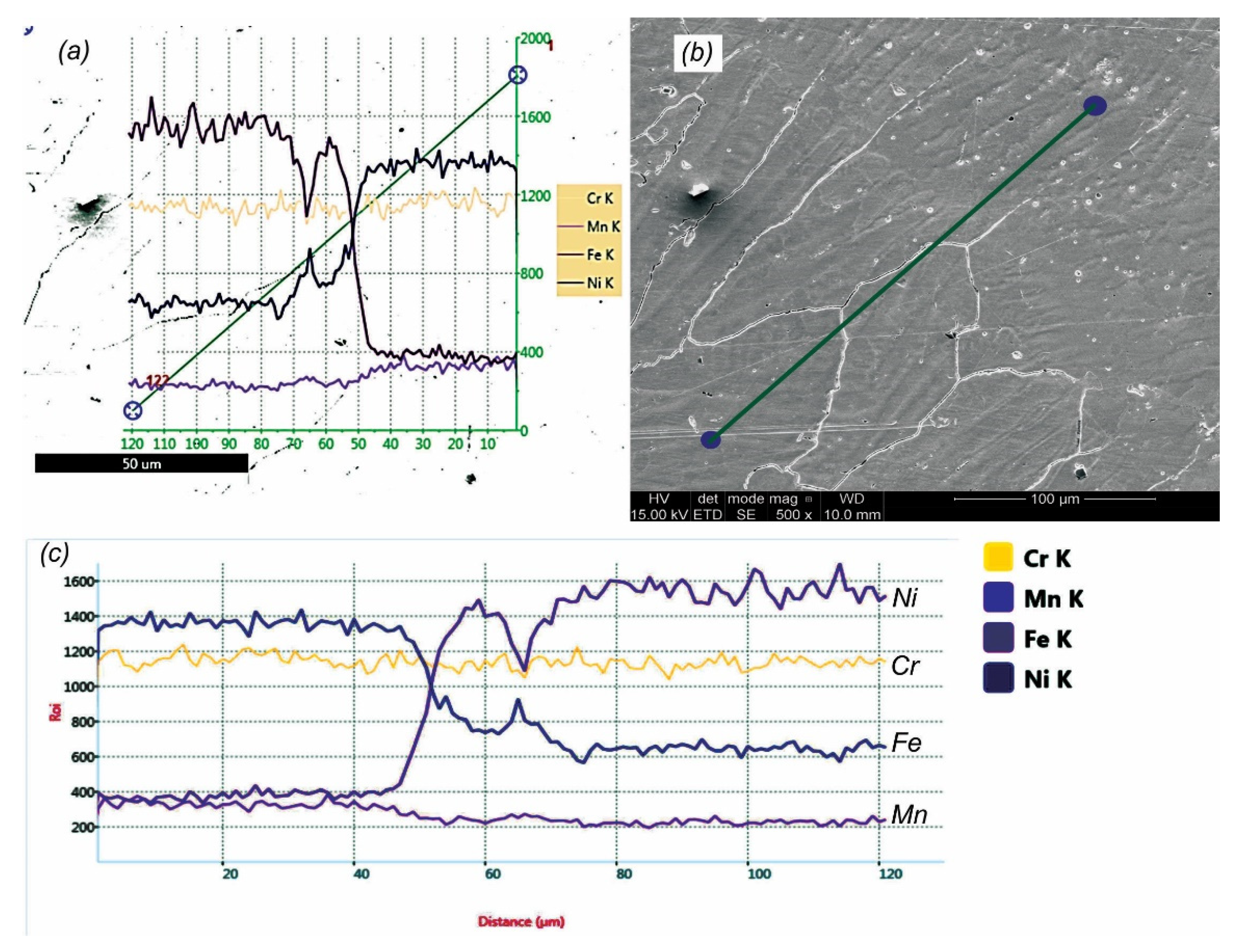
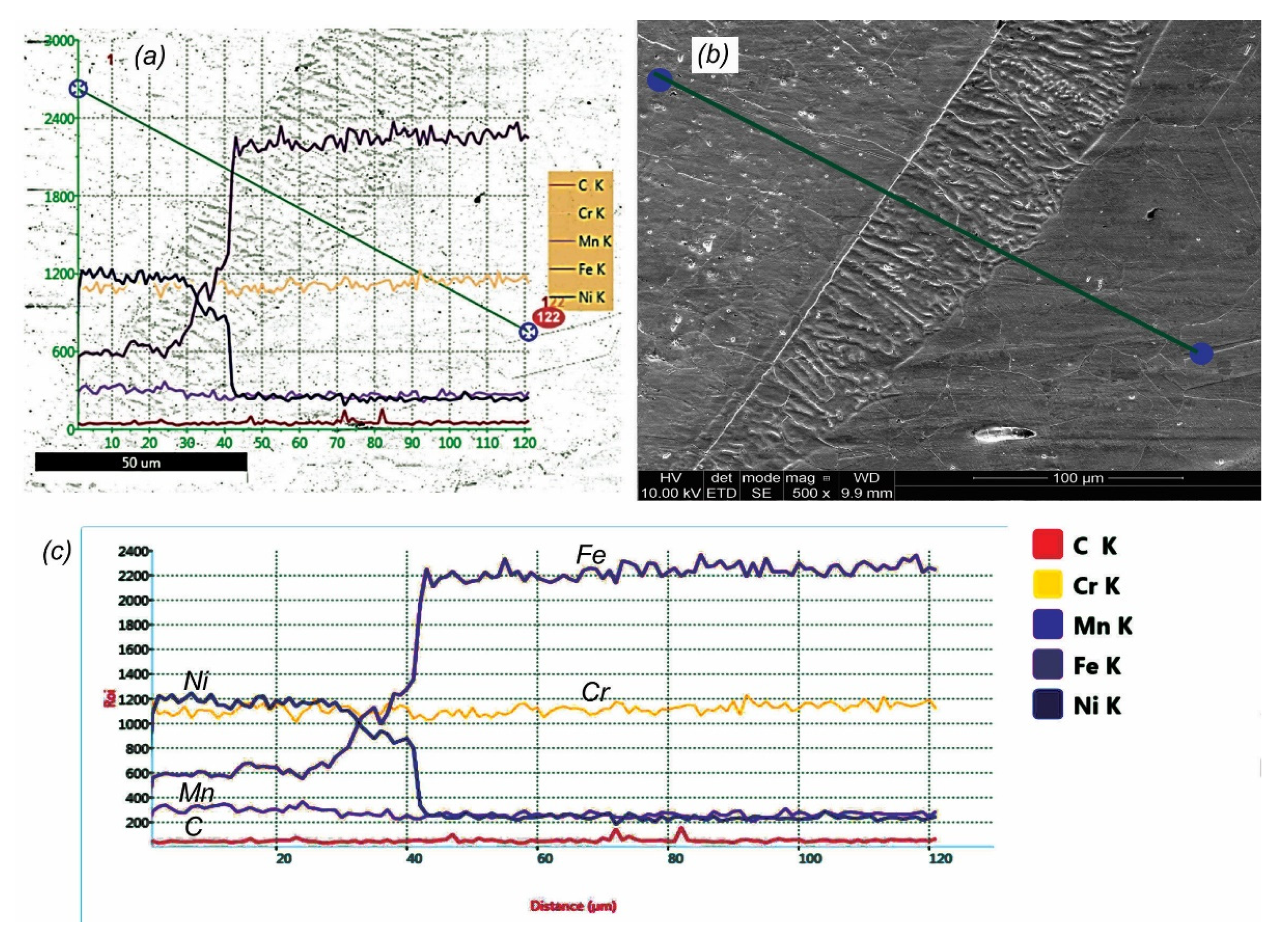
    • EDS analysis,
    • Confocal microscopy,
    • Microhardness measurements.
The tests were carried out in two stages: on preliminary test welded joints and on five test welded joints.

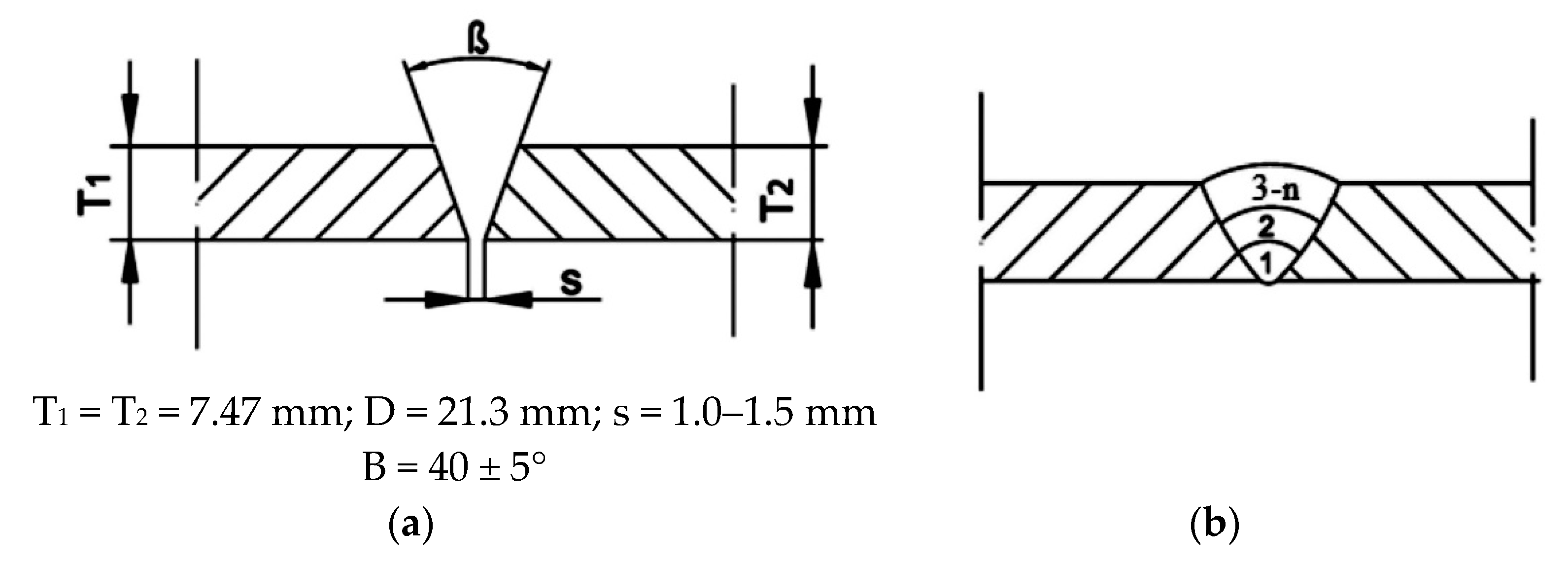
3.2. Welding Technology

For structural and operation reasons, the need to make welded joints of 304L austenitic stainless steel and Incoloy 800HT tubes appeared. Before welding, the tubes were beveled according to the scheme in Figure 1a. The proposed geometry of the welding groove enables full penetration and minimizes welding deformations by reducing the bevel angle, which is important because of the required dimensional tolerance of the tube system. Figure 1b shows the welding sequence.
Before welding the test joints, which were tested according to the research plan, preliminary test joints were made. This made it possible to identify and eliminate difficulties during welding and to determine the values of significant variables enabling us to obtain joints of quality level B according to ISO 5817 (including welding parameters). Shielding gas I1 (99.99% Ar) according to EN ISO 14175 from the face (10–12 l/min) and root side (forming gas 6–8 l/min) was used. A tungsten electrode with the designation WL-15 and a diameter of ϕ = 2.4 mm was used. Specimens were made in position H-L045 (6G) due to the destination location of the joint in the heat exchanger structure. The ambient temperature was 20 ± 2 °C. The elements were cleaned and degreased with acetone before welding. Preliminary welding tests showed the presence of welding imperfections such as cracks. Examples are shown in Figure 2.
The identified cracks occurred from the root side (Figure 2a,c) and the face side (Figure 2b,d) of the weld. Their shape is characteristic for hot cracks, i.e., they extend along the axis of the weld (Figure 2a,b) and propagate out from the center of the weld at its end (Figure 2d). The analysis of the welding process showed that the welding technique characteristic for austenitic stainless steels was one of the causes of the formation of this type of imperfection. It was changed through the use of straight beads, the distribution of liquid metal by mixing with a filler, making joints with an excess weld metal and filling the end crater with reinforcement. In addition, after each bead, the oxidized filler tip was cut off to eliminate the introduction of oxides into the liquid metal pool, which was not done for preliminary joints. This limited the appearance of liquid and brittle film from the segregation of impurities, which is one of the causes of crack formation [13]. The applied changes also led us to verify the welding parameters, which resulted in a decrease in the heat input. Those modifications brought positive results and allowed us to accept welding parameters. Test joints were made according to the parameters shown in Table 4. Five specimens were made: two were subjected to tensile tests, two to bending tests and one for other structural tests and microhardness measurements.

4. Results and Discussion

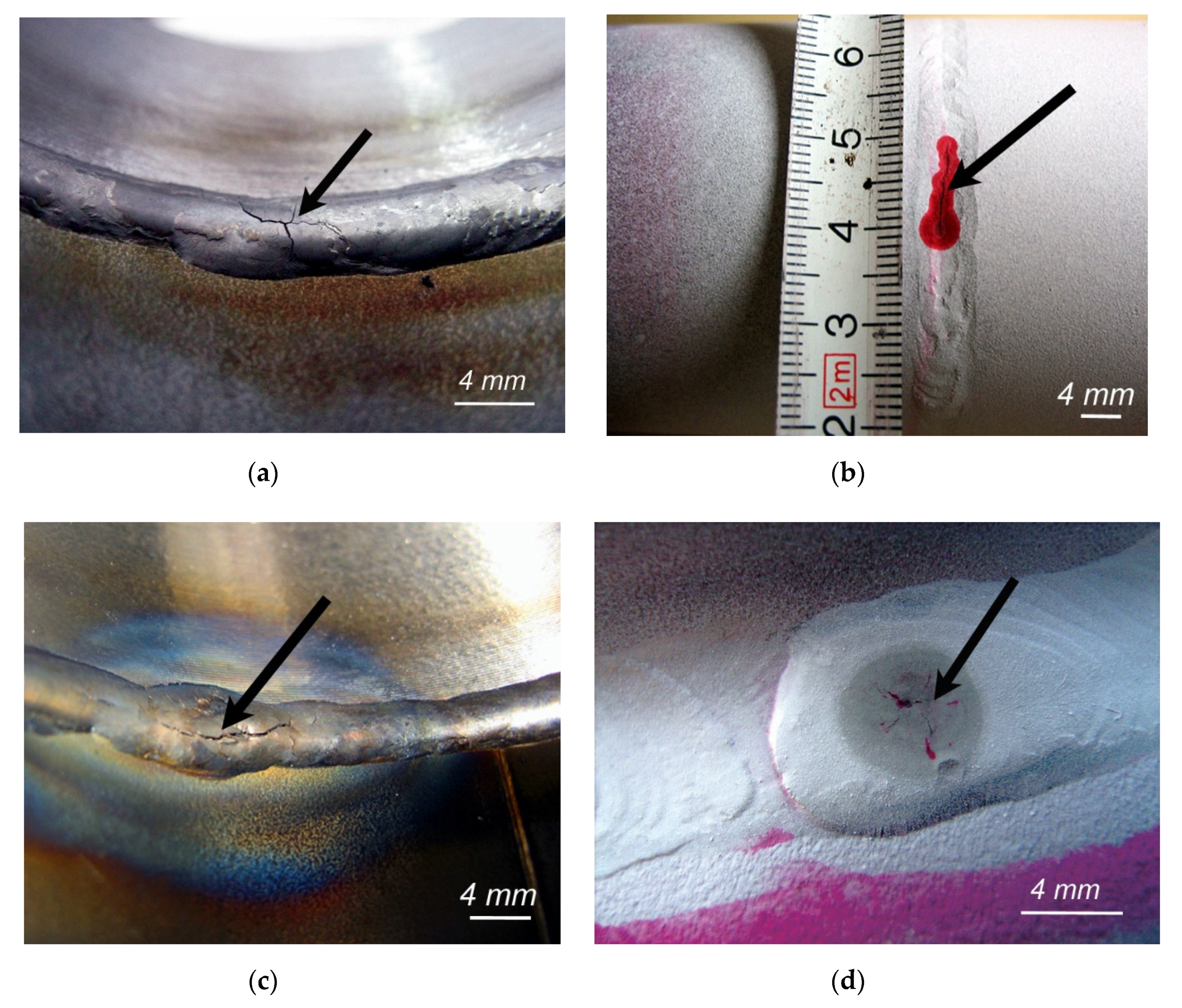
4.1. Nondestructive Testing

As part of nondestructive testing, tests were performed to detect surface imperfections (VT, PT) and weld imperfections (RT). All tested specimens obtained positive results of NDT tests. They were classified at quality level B in accordance with the requirements of EN ISO 5817, which was the assumed acceptance criterion. Figure 3 shows an example of a welded joint in general view and in cross-section.
Figure 3a shows the view of the face of the weld. A characteristic feature of this area for the material group being studied is low fluidity (high density) of the liquid metal pool. The consequence of this is the inability to obtain a characteristic clear, smooth face as in the case of the welding of austenitic stainless steels. All joints had the same weld face appearance. Figure 3b shows the cross section of the joint. As can be seen, the wall thickness of the tube is large relative to the outer diameter of the tube, which results in a small inner diameter. Thus, it is very important to shape and protect the root using forming gas. This requires the right flow rate to achieve laminar flow of the shielding gas. In the present case, sufficient values are 6–8 l/min. In addition to the proper formation of the root, this protected the surface against oxidation, which, when it occurs, may lead to the loss of corrosion resistance. After verification of the joints made on the basis of NDT and positive test results, they were subjected to destructive tests according to the presented research plan.

4.2. Destructive Testing

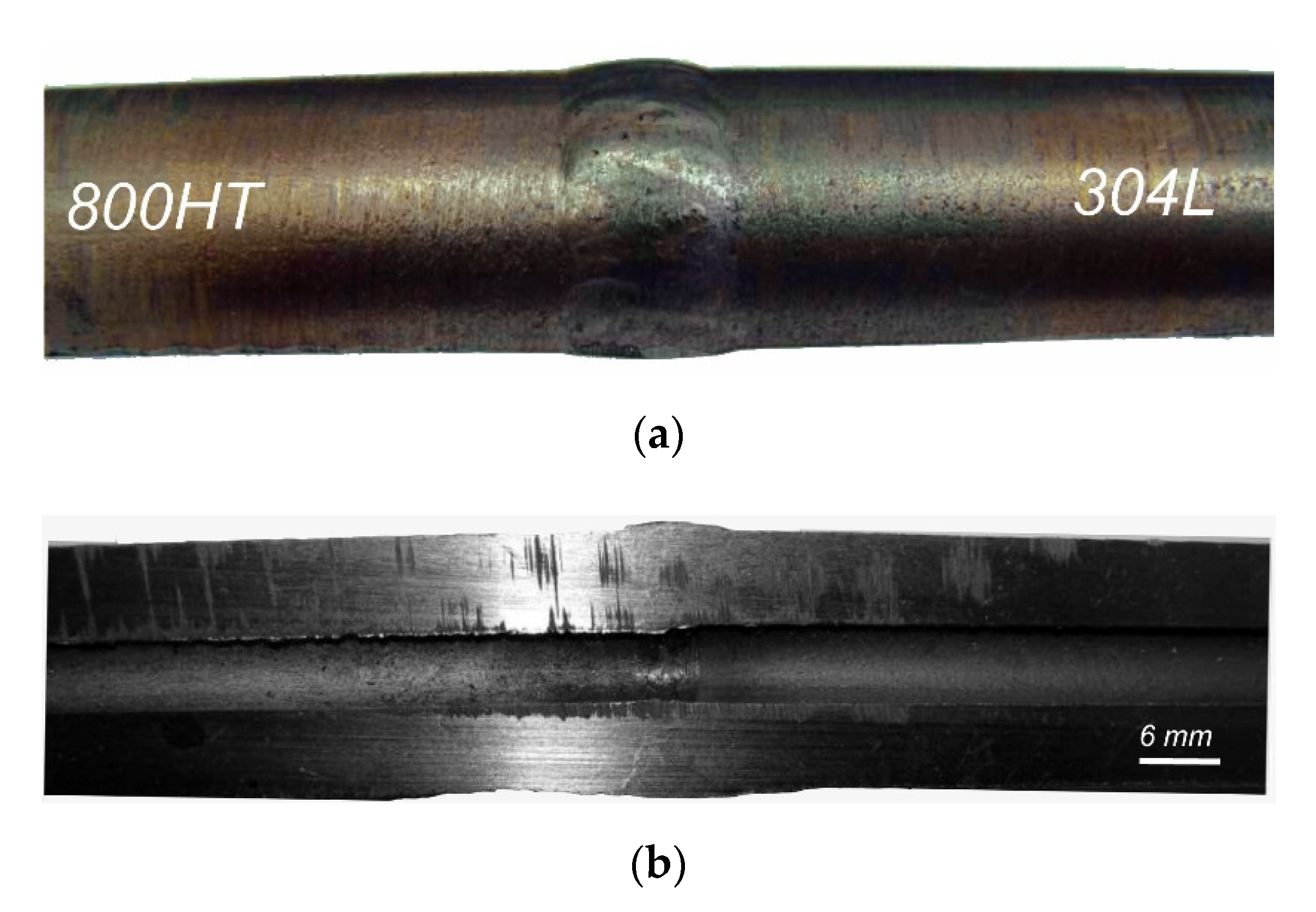
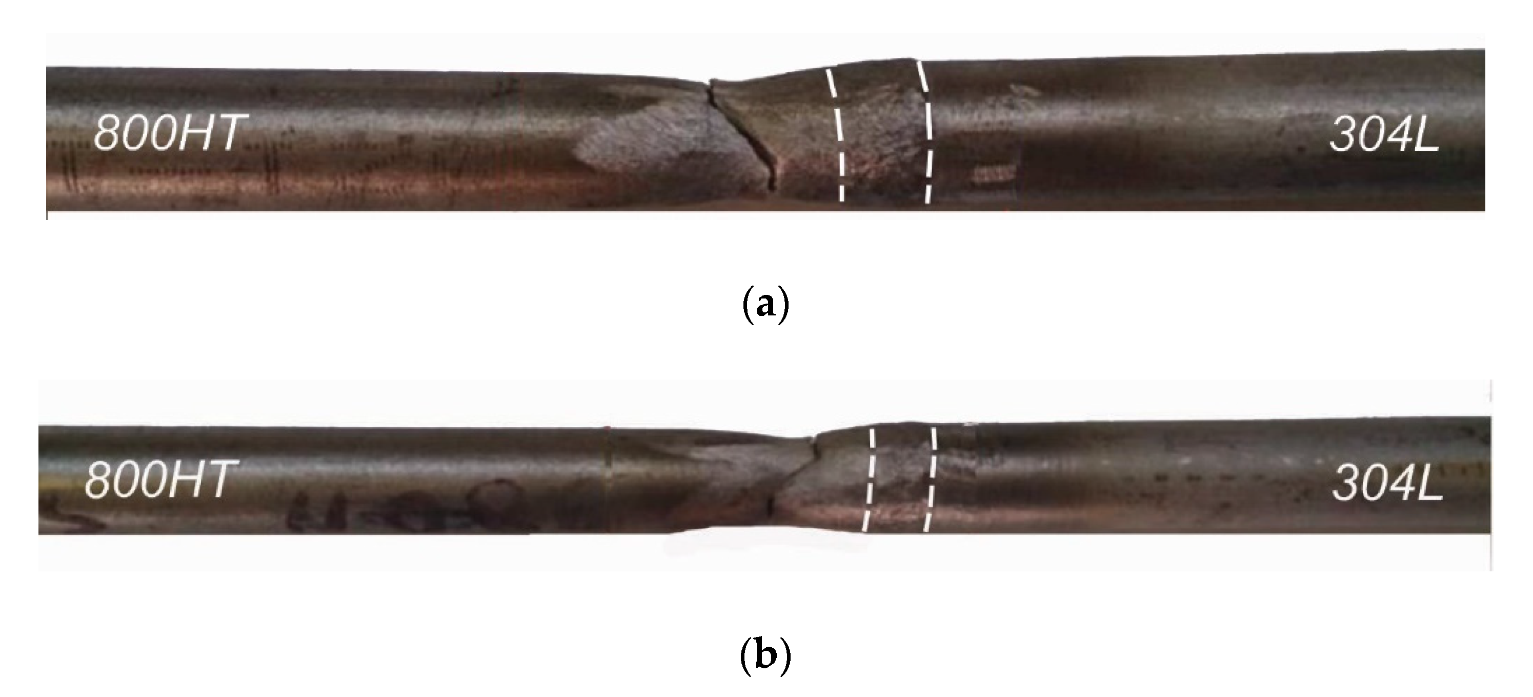
4.2.1. Static Tensile Test

Transverse tensile tests were carried out for two specimens, A and B (extended entire welded tube joint). Figure 4 presents the view of specimens after the tests. According to ASTM B 407, the minimum tensile strength of the Incoloy 800HT alloy is 450 MPa, and according to SA 312, the minimum tensile strength of the 304L austenitic stainless steel is 485 MPa. The acceptance criterion was the minimum tensile strength of the base material with a lower tensile strength, in this case Incoloy 800HT. The results of the test are presented in Table 5.
The obtained results meet the acceptance criterion: the obtained values are approximately 30% higher than the requirements. In addition, it was observed that a fracture occurred in the Incoloy 800HT base material. These results indicated that appropriate welding parameters had been applied in relation to the welding position (H-L045, 6G), that the welding consumable had been correctly selected, and that no imperfections occurred in the welded joints.

4.2.2. Bending Test

A bending test was carried out to determine the plastic properties of the welded joint. In addition, it is a test that reveals welding imperfections in the joint, e.g., lack of penetration, incomplete fusion, pores, etc. Two specimens were prepared for tensile the face (TFBB) and the root (TRBB) of the weld. A view of the specimens after bending is shown in Figure 5.
The obtained test results were considered positive. All specimens reached a bending angle of 180°. There were no cracks or other material defects on the tensiled surfaces. Even areas not subjected to assessment did not show welding imperfections. This proves the very good plastic properties and lack of welding imperfections in the tested specimens. Like the strength properties, the plastic properties are a derivative of the proper selection of the filler metal and welding parameters. The proposed bevel angle did not cause a reduction in the wettability of the filler or fusion of the tube walls, as evidenced by the lack of cracks and delaminations of the tensiled surfaces.

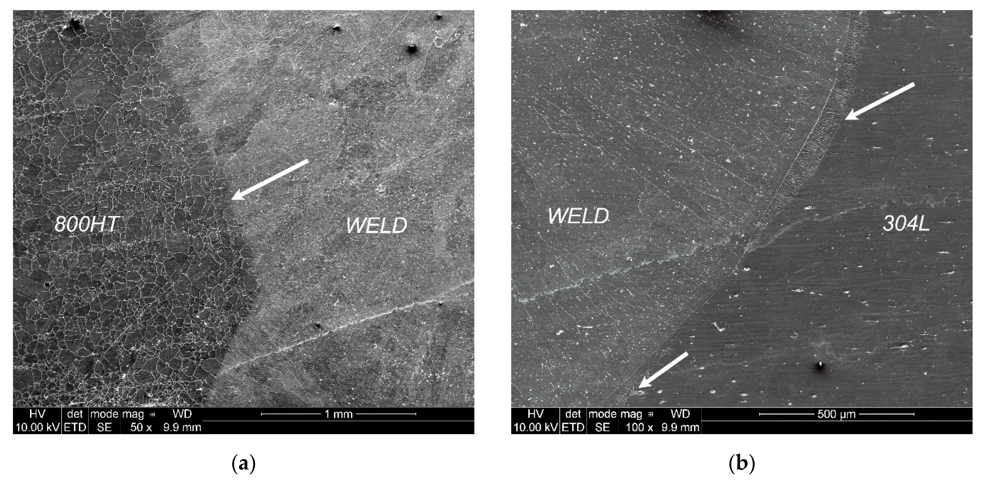
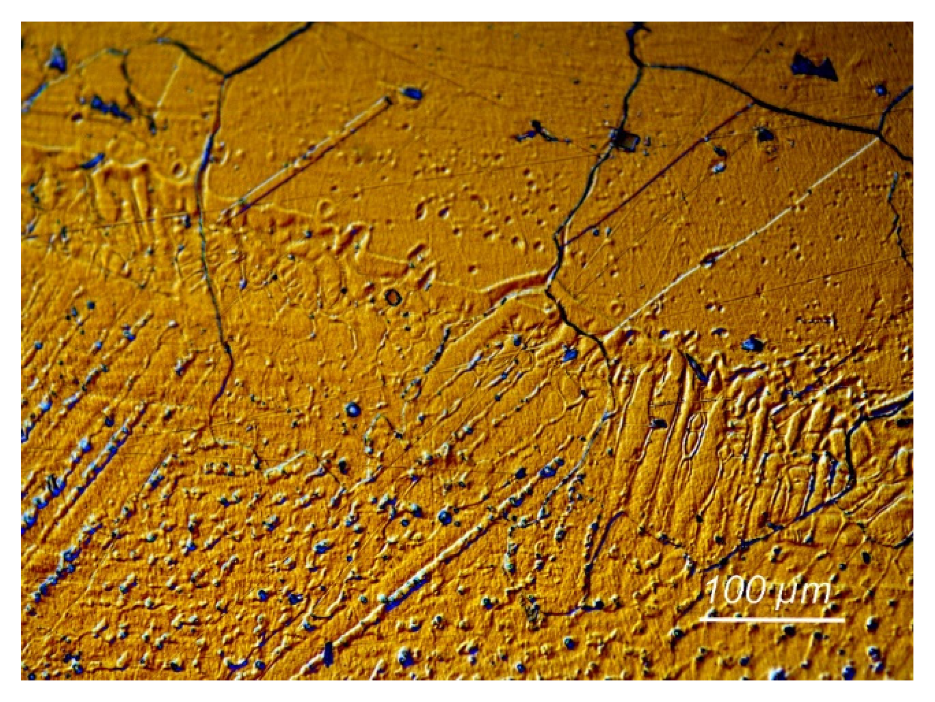
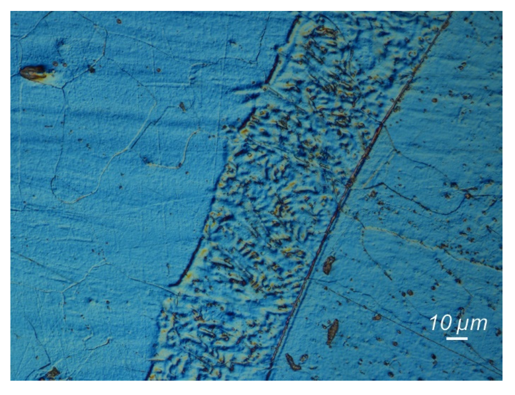
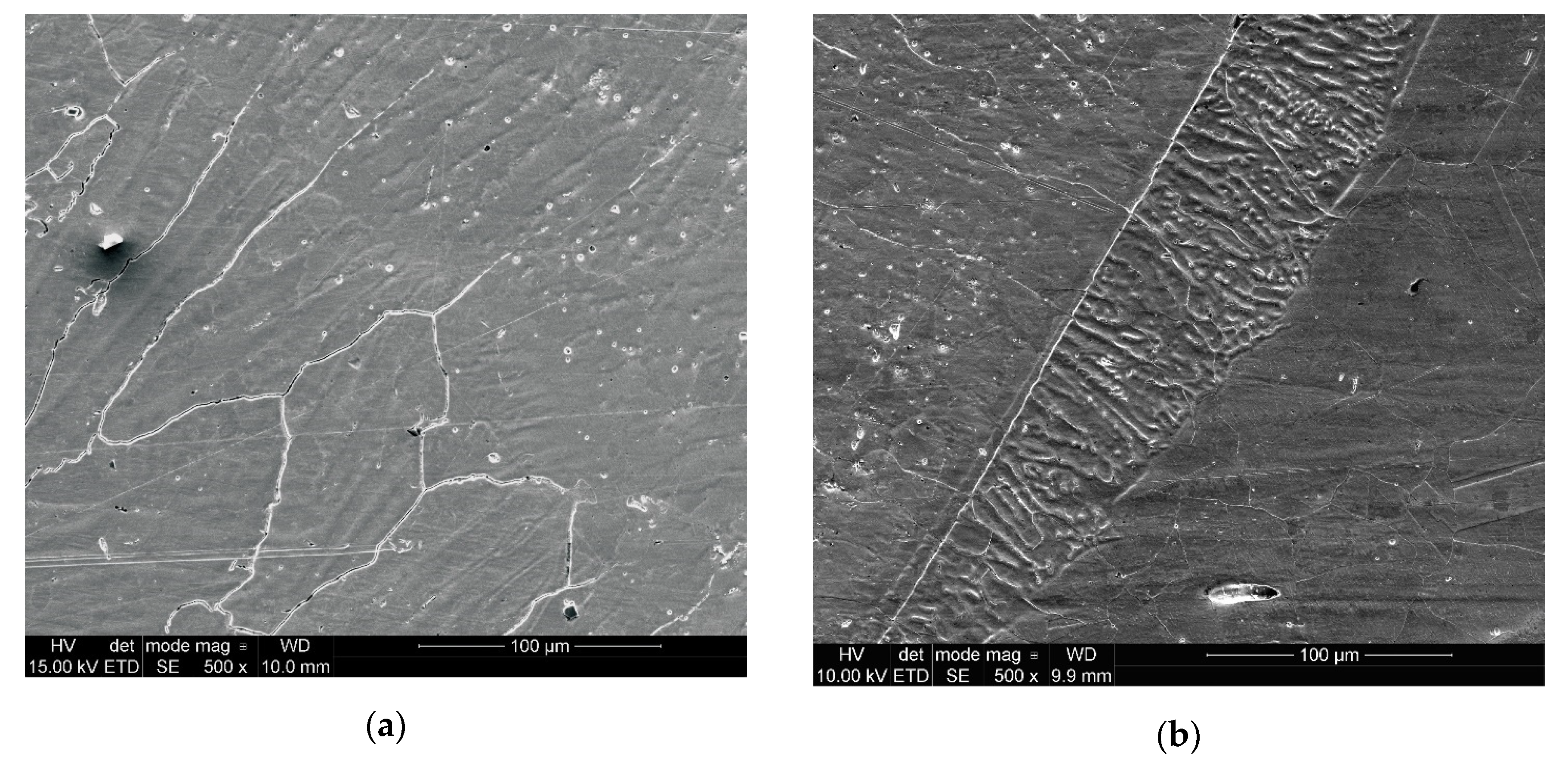
4.2.3. Macro- and Microscopic Examinations

Figure 6 presents a macroscopic view of a cross-section of the obtained dissimilar welded joint. There were no welding imperfections in the specimen, i.e., no cracks or porosity. The joint was symmetrical and was characterized by complete penetration and a smooth transition of the face into the base material. On the fusion line in 304L steel, white bands can be seen, which were formed as a result of structural changes. Metallographic microscopic tests were performed for base materials, weld and in the transition areas: weld–Incoloy 800HT and weld–304L stainless steel. Figure 7 shows the structure of base materials: Incoloy 800HT and 304L austenitic stainless steel. Incoloy 800HT is a solid solution with a full austenitic structure, many twins (Figure 7a) and Ti(N,C) precipitates (Figure 7b, indicated by an arrow). No changes were found relative to the typical structure of the material; 304L stainless steel has an austenitic structure (Figure 7c) with characteristic twins, slip bands and δ ferrite precipitates (Figure 7d). The structure of the tested 304L steel is correct. No structural anomalies caused by the manufacturing process, e.g., inadequate solution annealing, were identified for either material. Figure 8 shows the structure of the middle part of the weld. The weld has an equiaxed, fully austenitic structure with coarse and fine dendrites. Eutectics and microcracks were not detected in the weld.
Changing the arrangement of dendrites into columnar and their increase occurred in zones adjacent to the base material. Figure 9a,b show a view of the joint areas: Incoloy 800HT–fusion line–weld and weld–fusion line–304L stainless steel (white bands visible also in Figure 6). There are significant differences between the morphology of the fusion line and the HAZ for both materials (indicated by arrows), which is in accordance with the available literature [38]. From the Incoloy 800HT side, there is no clearly defined HAZ (type A fusion boundary); only at larger magnifications, a smooth transition of the weld metal into the base material can be observed (Figure 10). The morphology of the area between 304L stainless steel and the weld is different (type B fusion boundary). The areas of the smooth transition of weld to base material were observed, but there were also the zones of different morphologies (marked by the arrow in Figure 9b) which may indicate structural changes in this area. In order to analyze them, microscopic examinations (Figure 10 and Figure 11) were performed with higher magnification and the application of DIC (Nomarski contrast).
In the transition zone between the weld and Incoloy 800HT (Figure 10), columnar dendrites appearing towards the base material are visible. This may be due to the lower thermal conductivity of the Incoloy 800HT alloy (11.5 W/mK) compared to 304L stainless steel (14.0–16.3 W/mK). This leads to a slight dissipation of heat introduced during welding and the formation of the observed dendrite arrangement. Such changes were also observed by other researchers in welded joints of nickel alloys with austenitic stainless steel [38,44]. In the direction of the base material, melting of its grains and the epitaxial crystallization area, a transition of the dendritic structure of the weld in the crystallographic direction of the base material was observed. In the fusion zone, the grain shape of the primary structure (base material) can be observed. This type of crystallization is associated with relatively low thermal conductivity, low heat dissipation and a high density of the liquid metal. In the case oftransition zone: weld–304L stainless steel, this structure was not observed. However, areas with significant changes in morphology were identified, as revealed using the Nomarski contrast (Figure 11). Clearly defined spaces on the fusion line show the occurrence of high-temperature δ ferrite. Their intensity is associated with the higher thermal conductivity coefficient of 304L compared to the Incoloy 800HT and the welding position (H-L045), which generates varied heat distribution along the fusion line. Hence, the δ ferrite-rich zones do not occur along the entire length. The analyzed areas, despite structural and morphological differences, did not reveal imperfections in the form of microcracks or the formation of eutectics, which can be the result of introducing oxides or organic contaminations into the welding pool. No chromium carbide precipitations—that could lead to intergranular corrosion—were observed, which could result from the heat input during welding in the H-L045 position.
The next stage of the research was to determine the distribution of elements in transition zones. Figure 12 shows the areas subjected to this analysis, and Figure 13 and Figure 14 show theresults of the test.
In the transition zone on Incoloy 800HT, the proper change in the content of elements was found during an analysis of the linear distribution of the chemical elements. The change in chemical composition presented in Figure 13 indicates that the iron and nickel content in the fusion line changes significantly, which is an expected feature. The iron content increases after crossing the fusion line, and the nickel content decreases and corresponds to the content in the base material. No changes in chromium content were observed, suggesting no chromium carbide precipitates in this area. The manganese content decreased after crossing the fusion line. The contents of other elements were at the expected, correct levels. An analysis of the EDS linear distribution of the second transition zone, i.e., for 304L stainless steel, showed similar characteristics. Elemental distribution changes after crossing the fusion line were observed (Figure 14), and were the greatest for nickel and iron. These diffusive changes are slight compared to the transition zone of Incoloy 800HT. The presented research results suggest that no intermetallic phases were precipitated. The appropriate welding heat input and the use of straight beads (high cooling rate) allowed the reinforcing elements to remain in the solid solution. It also resulted in high strength, as revealed by mechanical tests.

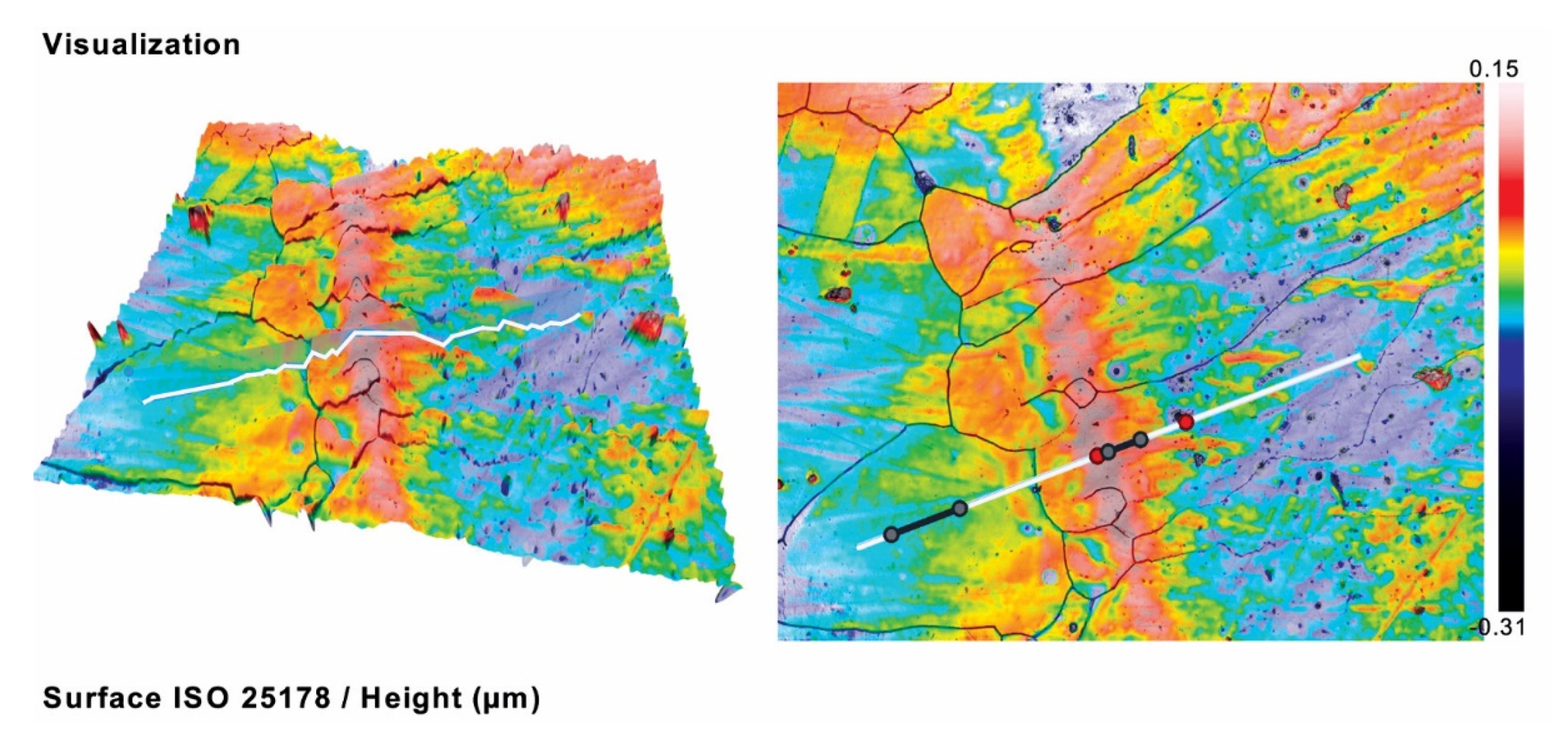
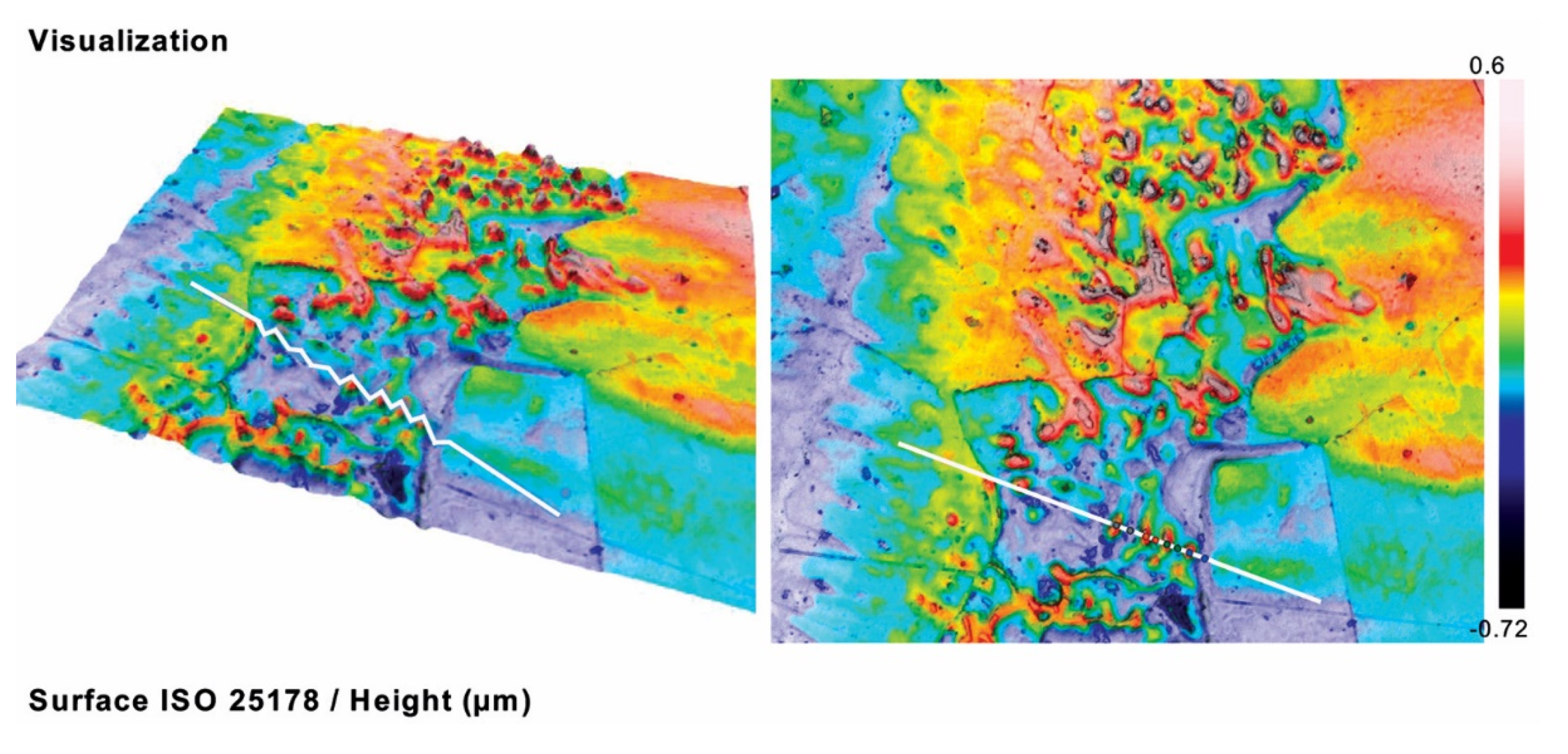
4.2.4. Confocal Microscopy

Microscopic metallographic examinations revealed differences in the structure of the transition areas between the weld and the base materials; therefore, a profile analysis of the morphology of the surface of the transition areas was carried out using a confocal microscope. The obtained results are shown in Figure 15 and Figure 16 and in Table 6.
The surface topography on both sides of the investigated joint showed the existence of transition zones between the base materials and the weld. These zones were associated with the influence of heat in the transition zone during the welding process. However, they have a different nature. In the case of Incoloy 800HT, a marked uniform hill of approximately 120 µm (maximum 150 µm) above the average surface was visible. In the second case, in the transition valley, single peaks of about 400 μm existed. The roughness of the specimens was evaluated by applying mean parameters such as root mean square height (Sq) and arithmetical mean height (Sa). Both of them demonstrate the general texture of the surfaces under investigation. Individual maximum and minimum height values do not affect both of these parameters (the differences were in the range of 15–20%). The maximum height (Sz) was 0.46 μm for Incoloy 800HT and 50× magnification and 1.32 µm for 304L stainless steel and 150x magnification. For the Incoloy 800HT specimen, the valley depths were predominant, and maximum pit depth (Sv) values reached 0.28 μm, i.e., approximately two times higher than the corresponding maximum peak height (Sp). In the second case, the surface was characterized by equaled distribution among peak heights and valley depths (Sp and Sv parameters were about 0.66 µm). The analyzed surfaces were in the form of a plateau with a concentration of the material near the profile tops which was represented by negative skewness Ssk (−0.36 for Incoloy 800HT alloy and −0.18 for 304L steel). A kurtosis (Sku) value higher than three for Incoloy 800HT (4.19) indicates the presence of a sharp structure of the profile. In the case of 304L steel, the structure was smoother (the Sku value was 2.83).

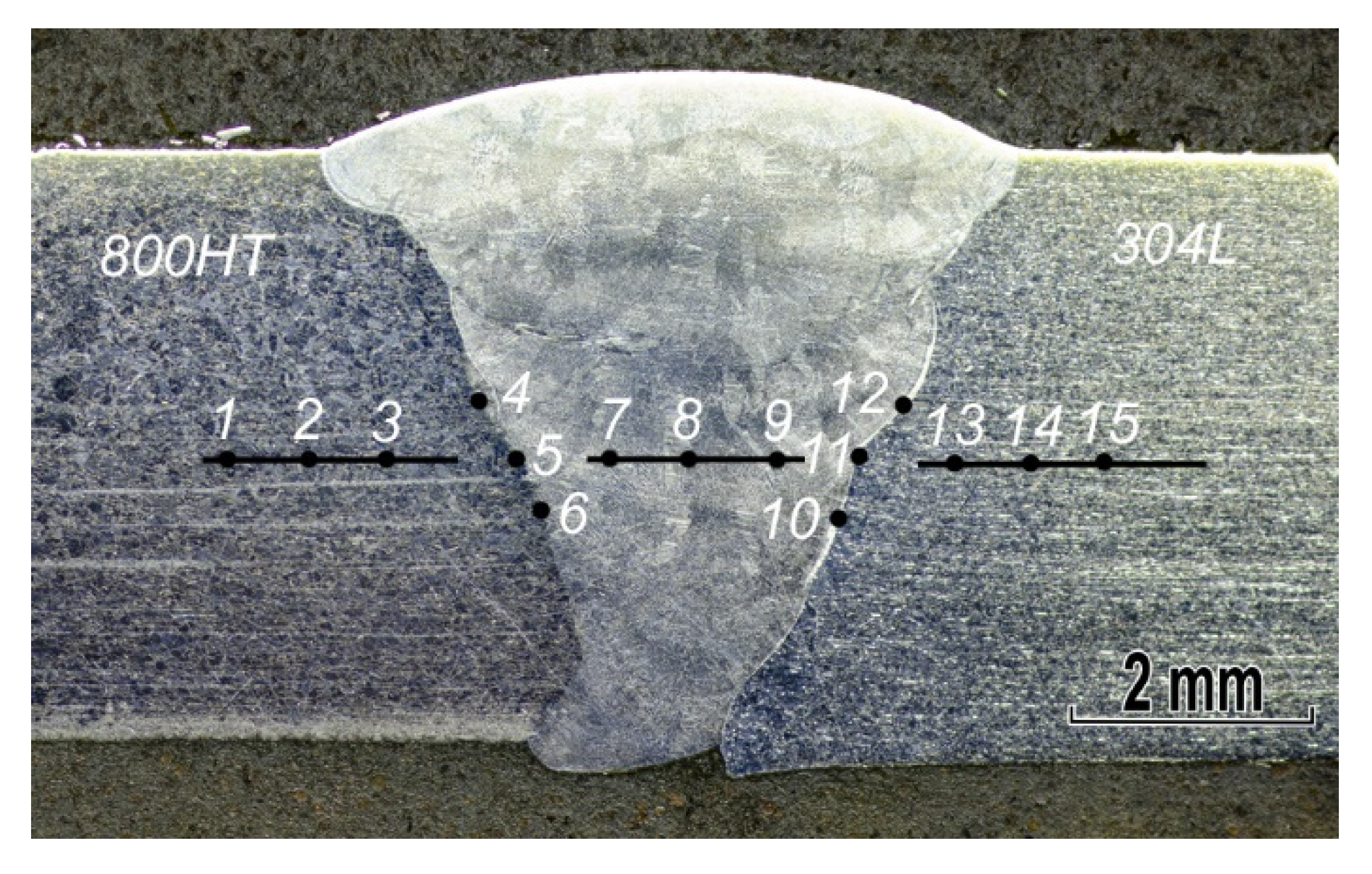
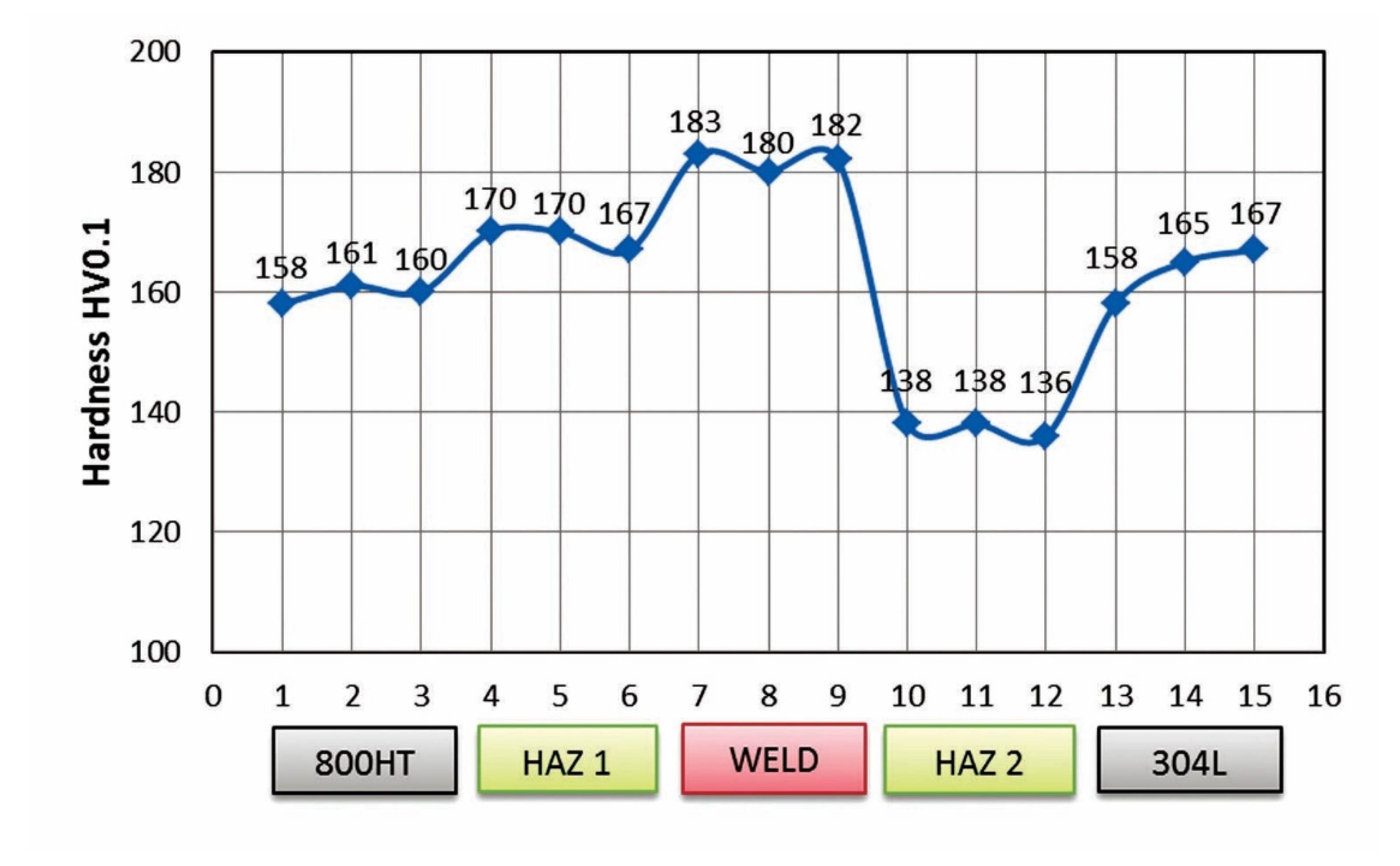
4.2.5. Microhardness Measurements

Microhardness measurements were made in base materials, weld and heat affected zones (paying special attention to transition zones) according to the arrangement of measurement points shown in Figure 17. Figure 18 shows the results of the measurements.
According to literature data, the microhardness for Incoloy 800HT nickel alloy is in the range of 120–250 HV0.1 [10,29,36]. In the considered case, this value was 158–161 HV0.1, which corresponds to the indicated range. In the heat affected zone (HAZ1), these values are slightly higher (average 169 HV), which indicates the appropriate heat input and cooling rate. The average HV0.1 value for weld metal is around 182 HV0.1. Such an increase can be explained by changes in the dendrite arrangement in the weld. The hardness for 304L steel reaches typical values for this grade [45]. However, a decrease in the HAZ2 area (average value 137 HV0.1) was observed, which results from the structure changes that were presented in microscopic studies (δ ferrite). The obtained results are characteristic of dissimilar nickel alloy and austenitic stainless steel welded joints, as also demonstrated by other authors [10,29,36,45].
Despite the fact that the hardness distribution (Figure 18) indicates a reduction in the hardness in HAZ of austenitic steel, both samples were fractured in Incoloy 800HT base material (Figure 4). This is not a typical result, but has already been reported in the literature for dissimilar joints of nickel alloy and austenitic stainless steel [39].

5. Summary

The difficult operating conditions of heat exchanger components necessitate the usage of materials with properties which are suitably matched to the environment, and the welding of dissimilar joints [9,47,48]. TIG welding of dissimilar Incoloy 800HT nickel alloy and 304L austenitic stainless steel welded joints gave positive results, despite initial problems associated with hot crack formation. They were eliminated by changing the welding technique (straight beads, mixing with a filler) and a reduction of oxides introduced from the filler material (cutting off the oxidized filler tip). Based on NDT and DT, no welding imperfections were found in the tested joints. The tensile strength of the tested joints was higher than the value for Incoloy 800HT (base material with lower mechanical properties). The results of the bending test showed good plasticity of the joint. Macroscopic examinations showed the correct structure of the joint. Microstructural studies revealed various types of structure and morphology in the transition zone between the weld and base materials. They were derived from the heat input value (different heat distribution and cooling effects during solidification and crystallization). SEM microscopic studies with the EDS technique allowed us to study the chemical composition of the welded joint. They revealed typical changes of alloying elements in the studied zones, which caused a lack of precipitations that could reduce the joint properties. Confocal microscopy studies also showed differences in transition zones expressed by changes in roughness. This method seems to be developmental, e.g., in relation to the determination of δ ferrite depending on roughness. Microhardness measurements showed the highest values in the weld, the lowest in HAZ from the 304L austenitic stainless steel side. This distribution is a consequence of structural changes caused by the influence of the welding thermal cycle.
Due to the specific geometry of welded tubes (diameter of the inner hole smaller compared to the wall thickness of the tube), reduction of the bevel angle, difficult welding position (H-L045) and, as a consequence, specific welding current parameters, the heat distribution conditions differ significantly from those that are characteristic for welding tubes of typical dimensions and sheets in a flat position (PA). In the lower part of the tube, the heat input value is higher compared to its upper surface. This can lead to changes in grain size and the formation of TiC and TiN precipitates directly behind HAZ in Incoloy 800HT alloy side. Their presence makes it possible to maintain the high strength properties of Incoloy 800HT alloy at high temperatures. However, at room temperature, these properties are lower than for 304L austenitic stainless steel, as demonstrated by product standards SA312 and SB 407. A decrease in hardness in HAZ does not always lead to a reduction in strength, especially for steel with a single phase structure.

Author Contributions

Conceptualization, G.R.; formal analysis, G.R., A.Ś., M.L. and D.F.; investigation, G.R. and M.L.; methodology, G.R. and M.L.; writing–original draft, G.R., A.Ś. and D.F.; writing–review & editing, G.R., A.Ś. and D.F. All authors have read and agreed to the published version of the manuscript.

Funding

This research received no external funding.

Acknowledgments

Authors want to thank Secespol Sp. z o.o. from Nowy Dwór Gdański for providing the material for welding of joints and Michał Dobrzyński from Gdańsk University of Technology for a valuable discussion.

Conflicts of Interest

The authors declare no conflict of interest.

References

  1. Mytsyk, B.; Ivanytsky, Y.; Hembara, O.; Kost, Y.; Shtayura, S.; Sakharuk, O. Effects of hydrogen influence on strained steel 1020. Int. J. Hydrog. Energy 2020, 45, 10199–10208. [Google Scholar] [CrossRef]
  2. Świerczyńska, A.; Fydrych, D.; Landowski, M.; Rogalski, G.; Łabanowski, J. Hydrogen embrittlement of X2CRNiMoCuN25-6-2- super duplex stainless steel welded joints under cathodic protection. Constr. Build. Mater. 2020, 238, 117697. [Google Scholar] [CrossRef]
  3. Wasim, M.; Djukic, M.B. Hydrogen embrittlement of low carbon structural steel at macro-, micro-and nano-levels. Int. J. Hydrog. Energy 2020, 45, 2145–2156. [Google Scholar] [CrossRef]
  4. Slobodyan, M.S.; Pavlov, S.K.; Remnev, G.E. Corrosion and high-temperature steam oxidation of E110 alloy and its laser welds after ion irradiation. Corros. Sci. 2019, 152, 60–74. [Google Scholar] [CrossRef]
  5. Chmielewski, T.; Hudycz, M.; Krajewski, A.; Sałaciński, T.; Skowrońska, B.; Świercz, R. Structure investigation of titanium metallization coating deposited onto AlN ceramics substrate by means of friction surfacing process. Coatings 2019, 9, 845. [Google Scholar] [CrossRef] [Green Version]
  6. Lisiecki, A.; Ślizak, D. Hybrid laser deposition of Fe-based metallic powder under cryogenic conditions. Metals 2020, 10, 190. [Google Scholar] [CrossRef] [Green Version]
  7. Kik, T.; Moravec, J.; Nováková, I. Numerical simulations of X22CrMoV12-1 steel multilayer welding. Arch. Metall. Mater. 2019, 64, 1441–1448. [Google Scholar] [CrossRef]
  8. Tomków, J.; Czupryński, A.; Fydrych, D. The abrasive wear resistance of coatings manufactured on high-strength low-alloy (HSLA) offshore steel in wet welding conditions. Coatings 2020, 10, 219. [Google Scholar] [CrossRef] [Green Version]
  9. Ali, M.; Ul-Hamid, A.; Alhems, L.M.; Saeed, A. Review of common failures in heat exchangers-Part I: Mechanical and elevated temperature failures. Eng. Fail. Anal. 2020, 109, 104396. [Google Scholar] [CrossRef]
  10. Ramkumar, K.D.; Mithilesh, P.; Varun, D.; Reddy, A.R.G.; Arivazhagan, N.; Narayanan, S.; Kumar, K.G. Characterization of microstructure and mechanical properties of Inconel 625 and AISI 304 dissimilar weldments. ISIJ Int. 2020, 54, 900–908. [Google Scholar] [CrossRef] [Green Version]
  11. Mani, C.; Karthikeyan, R.; Kannan, S. Electrochemical impedance analysis on cryogenically treated dissimilar metal welding of 316L stainless steel and monel 400 alloy using GTAW. Metals 2019, 9, 1088. [Google Scholar] [CrossRef] [Green Version]
  12. Golański, G.; Zieliński, A.; Sroka, M.; Słania, J. The effect of service on microstructure and mechanical properties of HR3C heat-resistant austenitic stainless steel. Materials 2020, 13, 1297. [Google Scholar] [CrossRef] [PubMed] [Green Version]
  13. Adamiec, J.; Konieczna, N. The welded joints structure of the Inconel 617 alloy designed for high temperature operation in supercritical parameters boilers. Arch. Metall. Mater. 2020, 65, 243–255. [Google Scholar] [CrossRef]
  14. Wang, J.F.; Sun, Q.J.; Wang, H.; Liu, J.P.; Feng, J.C. Effect of location on microstructure and mechanical properties of additive layer manufactured Inconel 625 using gas tungsten arc welding. Mater. Sci. Eng. A 2016, 676, 395–405. [Google Scholar] [CrossRef]
  15. Grudzień, M.; Tuz, L.; Pańcikiewicz, K.; Zielińska-Lipiec, A. Microstructure and properties of a repair weld in a nickel based superalloy gas turbine component. Adv. Mater. Sci. 2017, 17, 55–63. [Google Scholar] [CrossRef] [Green Version]
  16. Li, G.; Huang, J.; Wu, Y. An investigation on microstructure and properties of dissimilar welded Inconel 625 and SUS 304 using high-power CO2 laser. Int. J. Adv. Manuf. Technol. 2015, 76, 1203–1214. [Google Scholar] [CrossRef]
  17. Ming, H.; Wang, J.; Han, E.H. Comparative study of microstructure and properties of low-alloy-steel/nickel-based-alloy interfaces in dissimilar metal weld joints prepared by different GTAW methods. Mater. Charact. 2018, 139, 186–196. [Google Scholar] [CrossRef]
  18. Tumer, M.; Karahan, T.; Mert, T. Evaluation of microstructural and mechanical properties of dissimilar Inconel 625 nickel alloy–UNS S32205 duplex stainless steel weldment using MIG welding. Weld. World 2020, 64, 21–35. [Google Scholar] [CrossRef]
  19. Payão Filho, J.D.C.; Passos, E.K.D.; Gonzaga, R.S.; Ferreira, R.F.; Santos, D.D.; Juliano, D.R. Ultrasonic inspection of a 9% Ni steel joint welded with Ni-based superalloy 625: Simulation and experimentation. Metals 2018, 8, 787. [Google Scholar] [CrossRef] [Green Version]
  20. Wang, Y.; Shao, C.; Cui, H.; Fan, M.; Ma, N.; Lu, F. Failure competition behavior of 9Cr/617 dissimilar welded joint during LCF test at elevated temperature. Mater. Sci. Eng. A 2020, 773, 138810. [Google Scholar] [CrossRef]
  21. Ahmad, H.W.; Chaudry, U.M.; Tariq, M.R.; Bae, D.H. Assessment of fatigue and electrochemical corrosion characteristics of dissimilar materials weld between alloy 617 and 12 Cr steel. J. Manuf. Process. 2020, 53, 275–282. [Google Scholar] [CrossRef]
  22. Hejripour, F.; Aidun, D.K. Consumable selection for arc welding between stainless steel 410 and Inconel 718. J. Mater. Proc. Technol. 2017, 245, 287–299. [Google Scholar] [CrossRef]
  23. Dong, L.; Zhang, X.; Han, Y.; Peng, Q.; Deng, P.; Wang, S. Effect of surface treatments on microstructure and stress corrosion cracking behavior of 308L weld metal in a primary pressurized water reactor environment. Corros. Sci. 2020, 166, 108465. [Google Scholar] [CrossRef]
  24. DuPont, J.N.; Lippold, J.C.; Kiser, S.D. Welding Metallurgy and Weldability of Nickel Base Alloys; John Wiley & Sons, Inc.: Hoboken, NJ, USA, 2009. [Google Scholar]
  25. Kumar, S.A.; Sathiya, P. Effects of heat input on the mechanical and metallurgical characteristics of TIG welded Incoloy 800HT joints. Arch. Metall. Mater. 2017, 62, 1673–1679. [Google Scholar] [CrossRef] [Green Version]
  26. Sreevidya, N.; Abhijith, S.; Albert, S.K.; Vinod, V.; Banerjee, I. Failure analysis of service exposed austenitic stainless steel pipelines. Eng. Fail. Anal. 2020, 108, 104337. [Google Scholar] [CrossRef]
  27. Mortezaie, A.; Shamanian, M. An assessment of microstructure, mechanical properties and corrosion resistance of dissimilar welds between Inconel 718 and 310S austenitic stainless steel. Int. J. Pres. Ves. Pip. 2014, 116, 37–46. [Google Scholar] [CrossRef]
  28. Dokme, F.; Kulekci, M.K.; Esme, U. Microstructural and mechanical characterization of dissimilar metal welding of Inconel 625 and AISI 316L. Metals 2018, 8, 797. [Google Scholar] [CrossRef] [Green Version]
  29. Shakil, M.; Ahmad, M.; Tariq, N.H.; Hasan, B.A.; Akhter, J.I.; Ahmed, E.; Mehmood, M.A.; Choudhry, M.A.; Iqbal, M. Microstructure and hardness studies of electron beam welded Inconel 625 and stainless steel 304L. Vacuum 2014, 110, 121–126. [Google Scholar] [CrossRef]
  30. Silva, G.M.D.; Ferreira, E.A.; Castro, J.A.D. Resistência à corrosão de juntas dissimilares dos aços AISI 316L e da liga Inconel 718. Soldagem Insp. 2019, 24, 1–11. [Google Scholar] [CrossRef]
  31. Demarque, R.; Silva, R.D.S.; Santos, E.P.D.; Castro, J.A.D. Avaliação de parâmetros de soldagem nas características de juntas dissimilares Inconel 718-Inox 316L soldadas pelo processo TIG autógeno. Soldagem Insp. 2018, 23, 380–392. [Google Scholar] [CrossRef] [Green Version]
  32. Kosturek, R.; Wachowski, M.; Śnieżek, L.; Gloc, M. The influence of the post-weld heat treatment on the microstructure of Inconel 625/carbon steel bimetal joint obtained by explosive welding. Metals 2019, 9, 246. [Google Scholar] [CrossRef] [Green Version]
  33. Fang, Y.J.; Jiang, X.S.; Mo, D.F.; Song, T.F.; Luo, Z.P. Microstructure and mechanical properties of the vacuum diffusion bonding joints of 4J29 Kovar alloy and 316L stainless steel using pure cobalt interlayer. Vacuum 2019, 168, 108847. [Google Scholar] [CrossRef]
  34. Mitelea, I.; Utu, I.D.; Urlan, S.D.; Crăciunescu, C.M. The effect of the solution treatment onto the microstructure and mechanical properties of MAG pulsed welded joints from X2CrNiMoN22-5-3 duplex stainless steels. Materialwiss. Werkstoff. 2017, 48, 1040–1048. [Google Scholar] [CrossRef]
  35. Rogalski, G.; Świerczyńska, A.; Fydrych, D.; Landowski, M. The influence of solution annealing temperature on the properties of Lean Duplex 2101 welded joints in tubes. Weld. Technol. Rev. 2019, 91, 49–59. [Google Scholar] [CrossRef]
  36. Ramkumar, K.D.; Patel, S.D.; Praveen, S.S.; Choudhury, D.J.; Prabaharan, P.; Arivazhagan, N.; Xavior, M.A. Influence of filler metals and welding techniques on the structure–property relationships of Inconel 718 and AISI 316L dissimilar weldments. Mater. Des. 2014, 62, 175–188. [Google Scholar] [CrossRef]
  37. Wang, W.; Lu, Y.; Ding, X.; Shoji, T. Microstructures and microhardness at fusion boundary of 316 stainless steel/Inconel 182 dissimilar welding. Mater. Charact. 2015, 107, 255–261. [Google Scholar] [CrossRef]
  38. Wang, W.; Han, Y.; Liu, T.; Lu, Y.; Shoji, T. Effect of surface potential on corrosion behavior of the fusion boundary in the dissimilar welds between 316L stainless steels and Inconel 182 alloy. J. Mater. Sci. 2020, 55, 774–785. [Google Scholar] [CrossRef]
  39. Ramkumar, T.; Selvakumar, M.; Narayanasamy, P.; Begam, A.A.; Mathavan, P.; Raj, A.A. Studies on the structural property, mechanical relationships and corrosion behaviour of Inconel 718 and SS 316L dissimilar joints by TIG welding without using activated flux. J. Manuf. Process. 2017, 30, 290–298. [Google Scholar] [CrossRef]
  40. Kumar, K.G.; Ramkumar, K.D.; Arivazhagan, N. Characterization of metallurgical and mechanical properties on the multi-pass welding of Inconel 625 and AISI 316L. J. Mech. Sci. Techol. 2015, 29, 1039–1047. [Google Scholar] [CrossRef]
  41. Sayiram, G.; Arivazhagan, N. Microstructural characterization of dissimilar welds between Incoloy 800H and 321 austenitic stainless steel. Mater. Charact. 2015, 102, 180–188. [Google Scholar] [CrossRef]
  42. Zhou, S.; Chai, D.; Yu, J.; Ma, G.; Wu, D. Microstructure characteristic and mechanical property of pulsed laser lap-welded nickel-based superalloy and stainless steel. J. Manuf. Process. 2017, 25, 220–226. [Google Scholar] [CrossRef]
  43. Ramkumar, K.D.; Prabu, S.S.; Arivazhagan, N. Investigation on the fusion zone microstructures and mechanical integrity of AISI 904L and Inconel 625 weld joints. Mater. Res. Express 2015, 6, 086540. [Google Scholar] [CrossRef]
  44. Hosseini, H.S.; Shamanian, M.; Kermanpur, A. Microstructural and weldability analysis of Inconel617/AISI 310 stainless steel dissimilar welds. Int. J. Pres. Ves. Pip. 2016, 144, 18–24. [Google Scholar] [CrossRef]
  45. Kourdani, A.; Derakhshandeh-Haghighi, R. Evaluating the properties of dissimilar metal welding between Inconel 625 and 316L stainless steel by applying different welding methods and consumables. Metal. Mater. Trans. 2018, 49, 1231–1243. [Google Scholar] [CrossRef]
  46. Safari, M.; Mostaan, H.; Derakhshan, E. Microstructual and mechanical studies of the dissimilar tabular joints of Incoloy alloy 825 and AISI 316 stainless steel. J. Mar. Eng. Technol. 2018, 18, 1–10. [Google Scholar] [CrossRef]
  47. Górka, J.; Przybyła, M.; Szmul, M.; Chudzio, A.; Ładak, D. Orbital TIG welding of titanium tubes with perforated bottom made of titanium-clad steel. Adv. Mater. Sci. 2019, 19, 55–64. [Google Scholar] [CrossRef] [Green Version]
  48. Bouzid, A.H.; Pourreza, M. Analysis of residual stresses in the transition zone of tube-to-tubesheet joints. J. Pressure Vessel Technol. 2019, 141. [Google Scholar] [CrossRef]
Figure 1. Scheme of (a) edge preparation for welding, (b) welding sequence.
Metals 10 00559 g001
Figure 2. Examples of welding imperfections identified after the preliminary welding tests (a) and (c) crack form the root; (b) and (d) cracks from the face. The arrows mark the cracks.
Metals 10 00559 g002
Figure 3. Example of a specimens (a) view from the face; (b) cross-section.
Metals 10 00559 g003
Figure 4. Specimens after transverse tensile test (a) specimen A; (b) specimen B. Dashed lines mark welds.
Metals 10 00559 g004
Figure 5. Specimens after bending tests.
Metals 10 00559 g005
Figure 6. Cross-section of the Incoloy 800HT nickel alloy–304L austenitic stainless steel welded joint.
Metals 10 00559 g006
Figure 7. Metallographic structure of (a) Incoloy 800HT nickel alloy–optical microscopy; (b) Incoloy 800HT nickel alloy–electron microscopy; (c) 304L austenitic stainless steel–optical microscopy; (d) 304L austenitic stainless steel–electron microscopy.
Metals 10 00559 g007
Figure 8. Metallographic structure in the middle part of weld metal.
Metals 10 00559 g008
Figure 9. SEM micrograph showing interface between (a) weld–fusion line and Incoloy 800HT nickel alloy (type A fusion boundary) and (b) weld–fusion line and 304L austenitic stainless steel (type B fusion boundary).
Metals 10 00559 g009
Figure 10. Micrograph showing interface between weld–fusion line and Incoloy 800HT nickel alloy (Nomarski contrast).
Metals 10 00559 g010
Figure 11. Micrograph showing interface between weld–fusion line and 304L austenitic stainless steel (Nomarski contrast).
Metals 10 00559 g011
Figure 12. SEM micrograph showing interface between (a) weld–fusion line and Incoloy 800HT nickel alloy and (b) weld–fusion line and 304L austenitic stainless steel.
Metals 10 00559 g012
Figure 13. Results of EDS linear analysis for the zone: Incoloy 800HT nickel alloy (a) distribution of elements against the background of the structure with the measuring line marked; (b) microstructure of the weld area–HAZ–Incoloy 800HT nickel alloy with the line according to which the elements were measured; (c) linear distribution of elements.
Metals 10 00559 g013
Figure 14. Results of EDS linear analysis for the zone: 304L austenitic stainless steel (a) distribution of elements against the background of the structure with the measuring line marked; (b) microstructure of the weld area–HAZ–304L austenitic stainless steel with the line according to which the elements were measured; (c) linear distribution of elements.
Metals 10 00559 g014
Figure 15. Test results of profile analysis for the zone of Incoloy 800HT nickel alloy. The analysis was performed along the white line.
Metals 10 00559 g015
Figure 16. Test results of profile analysis for the zone of 304L austenitic stainless steel. The analysis was performed along the white line.
Metals 10 00559 g016
Figure 17. The arrangement of measurement points on the specimen for microhardness measurements.
Metals 10 00559 g017
Figure 18. Microhardness distribution across the welded joint.
Metals 10 00559 g018
Table 1. Chemical composition and mechanical properties of 304L stainless steel according to the inspection certificate.
Chemical Composition [wt. %]
CSiMnPSCrNiN
0.0140.411.560.0210.00818.1810.240.070
Mechanical Properties
Rp0.2 [MPa]Rp1.0 [MPa]Rm [MPa]A50 [%]
31236259964
Table 2. Chemical composition and mechanical properties of Incoloy 800HT nickel alloy according to the inspection certificate.
Chemical Composition [wt. %]
CSiMnPSCrNiCuTiAlFe
0.0720.480.790.0180.00119.2530.200.180.540.4347.6
Mechanical Properties
Rp0.2 [MPa]Rm [MPa]A50 [%]Grain Size ASTM E112
20258257Nr. 6
Table 3. Chemical composition and mechanical properties at the 20 °C of S Ni 6082 filler metal according to the inspection certificate.
Chemical Composition [wt. %]
CSiMnPSCrNiCuTiNbFe
<0.01<0.13.10.0010.00120.573.0<0.10.42.50.2
Mechanical Properties
Rp0.2 [MPa]Rm [MPa]A (L0 = 5d) [%]KV [J]
≥400≥620≥35≥150
Table 4. Welding parameters for test joints.
Run *Welding ProcessSize of Filler Metal [mm] Welding Current [A]Arc Voltage [V]Type of Current/ PolarityTravel Speed [mm/s]Heat ** Input [kJ/mm]
1141 (TIG)2.060–11010.5–11.0DC-1.2–2.50.2–0.6
2-n141 (TIG)2.080–1109.0–10.0DC-1.2–2.50.2–0.6
* See welding sequence in Figure 1b. ** Heat input calculated according to EN 1011-1.
Table 5. Tensile test results of welded joints.
No SpecimensCalculation Cross-Section, So [mm2]Total Loading Force, Ib [kN] Tensile Strength, Rm [MPa]Place of Fracture
1321.5188584Base material Incoloy 800HT
2312.5184589Base material Incoloy 800HT
Table 6. 3D surface texture parameters of the specimens under investigation.
ZoneSa [µm]Sq [µm]Sp [µm]Sv [µm]Sz [µm]Sku [µm]Ssk [µm]
Weld–HAZ–800HT nickel alloy0.04 0.060.170.280.464.19−0.36
Weld–HAZ–304L stainless steel0.16 0.200.650.661.322.83−0.18

