Tensile-Shear Mechanical Behaviors of Friction Stir Spot Weld and Adhesive Hybrid Joint: Experimental and Numerical Study

State Key Laboratory of Automobile Simulation and Control, Jilin University, Changchun 130022, China
*
Author to whom correspondence should be addressed.
Metals 2020, 10(8), 1028; https://doi.org/10.3390/met10081028
Submission received: 27 June 2020
/
Revised: 25 July 2020
/
Accepted: 27 July 2020
/
Published: 31 July 2020
(This article belongs to the Special Issue Advanced Process Technologies Based on Friction Stir Welding and Linear Friction Welding)
Abstract
:In this work, the tensile-shear mechanical behaviors of friction stir spot weld and adhesive hybrid joint were performed from both numerical and experimental viewpoints. Weld through (WT) and flow in (FI) processes were studied in this research. The focus was to evaluate joint defects, tensile-shear failure load (TSFL), failure energy, failure mode and stress distribution of the joint. In FI joints, keyhole and hook defects appeared in the weld zone and the areas of material removed from the base metal were filled with adhesive. In the WT joints, the adhesive layer close to the weld zone was carbonized due to the welding heat. Meanwhile, under the rotating movement of welding tool, the adhesive impurities entered the stirring zone (SZ) and heat affected zone (HAZ) of the weld, which decreased mechanical performances of WT joints. Compared to the friction stir spot welding (FSSW) joint, the TSFL value, stiffness and failure energy of FI joint were increased by 2.7, 1.1 and 8.14 times, respectively. In order to study the stress distribution of the joints, a finite element (FE) model, which considered the weld structure and mechanical properties of weld regions, was implemented. Moreover, the adhesive layer was simplified by the cohesive zone model (CZM). FE results show that the FI process effectively decreases the stress concentration of the weld edge from 243.09 to 15.5 MPa, under the 2 kN tensile load. The weld can block the adhesive crack propagation, and the adhesive optimized the stress distribution of FI joints through a synergistic effect. So, the use of FI process for aluminum alloy connection is strongly recommended, especially in crucial structure areas.
1. Introduction
As a result of the huge consumption of natural resources and global warming, many countries have enacted legislation to reduce fuel consumption and greenhouse gas emissions [1,2]. Manufacturers in the automotive and aerospace industries use lightweight materials such as aluminum and magnesium alloys to reduce structural weight in order to improve fuel efficiency and reduce CO2 emissions [3,4,5,6,7]. Aluminum alloy has been widely used in the field of transportation due to its low density, high strength-to-weight ratio and strong damping ability [8,9]. The structural application of aluminum alloys for the safety and reliability of motor vehicles inevitably involves the issues of welding and joining. Traditional welding processes, like resistance spot welding (RSW), have defects such as cracks and porosity in the joint during the welding process, which degrades the mechanical properties of the weld [10,11].
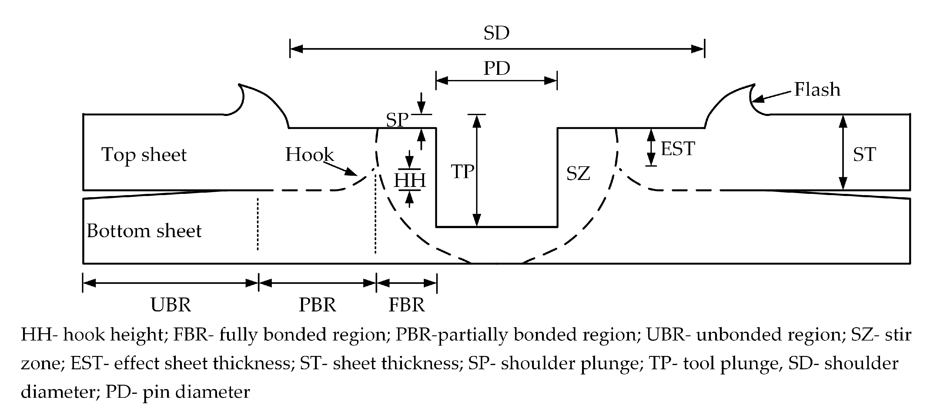
Friction stir welding (FSW) was introduced and patented by The Welding Institute (TWI) in 1991 [12,13]. FSW is a solid-state joining process, which means that base metals can be joined at a temperature below their melting point. Friction stir spot welding (FSSW) has been developed as a derivative of FSW for joining automobile body structures [14]. FSSW is performed on overlap sheets without translation of a welding tool. The FSSW process is widely used in the joining of lightweight metals (aluminum, magnesium, copper alloys, etc.) and polymers (polypropylene, polycarbonate, polyethylene, etc.) [15,16,17,18]. An extensive amount of research has been conducted by FSW and FSSW, focusing on the process–structure–performance relationship of the weld [12]. Process parameters include tool parameters (tool rotation speed, plunging time and plunge depth) and welding parameters (shape and diameter of tool shoulder, shape and diameter of tool probe and probe pitch) [19,20]. The contribution of the tool shape to the tensile-shear failure load (TSFL) of the joint is 61.5%, the tool speed is 20.1% and insertion time is 18.4% [20]. Figure 1 illustrates the cross-sectional structure of a FSSW weld. The TSFL of a weld depends on the value of FBR and EST. The longer FBR and the higher EST correspond to superior joint performances. [21]. However, the keyhole in a FSSW weld leading to discontinuous weld material and the stress concentration due to the hook defect can weaken the mechanical properties of the weld [22].
Adhesive bonding (AB) is one of the most common joining techniques used in advanced structures (e.g., aerospace, racing and automobile bodies, marine). This joining technique has some special advantages compared to traditional joining methods, (like riveting, bolting and welding). AB joints have a higher load-bearing capacity by reducing stress concentrations [23]. In addition, this method can be combined with other joining processes to benefit from the advantages of them, such as spot welding and riveting. Due to the lower stress concentration in the joint area, this hybrid joint has a stronger connection capacity. The weld-bonded process is divided into two types: the “flow-in” (FI) and the “weld-through”(WT) method [24]. The FI method first welds the parts together. Then a low viscosity adhesive is used to flow into the gap of the overlap area by capillary action and subsequently cure. With the WT method, the adhesive is applied to the part, then spot welded and subsequently cured [25]. Pouranvari et al. compared shear tensile properties of martensitic stainless steel weld/adhesive hybrid joints [26]. Results show that TSFL and energy absorption of the weld-bonded joint were increased by 100% (from 6.7 to 13.6 kN) and 110% (from 1.9 to 4.1 J) compared to those of the RSW weld, respectively. Ren et al. compared static tensile-shear properties of laser welding (LW) and laser weld bonding joints [27]. Similar results were also found. Different from RSW and LW, the hybrid joint of FSSW and AB in the WT process has lower strength than FSSW joints. During the welding process, uncured adhesive affects the weld quality. In addition, welding heat degrades the effectiveness of the adhesive near the weld [28]. The FSSW process requires a certain residence time in order to adequately plasticize the material. This inevitably results in burn-up of the adhesive layer, which decreases performances of the hybrid joint [29]. At present, the hybrid joint of FSSW and AB is mainly focused on the WT method. Few research studies have been conducted on FI method joints. Moreover, systematic analysis of the failure mechanism and the stress distribution of FSSW hybrid joints is lacking.
In this work, an experimental and numerical study was carried out on two types of hybrid joints (FI and WT). For comparison purposes, the AB and FSSW joints were also included in this study. The experimental connection of metal coupons and subsequent testing were carried out under controlled laboratory conditions. The microstructure defects, the failure load and fracture behavior of the joint were compared, and the role of the adhesive layer was discussed. The cohesive zone model was used to simulate the mechanical behaviors of the adhesive layer and created a fine finite element (FE) model based on weld structure and mechanical properties in the weld regions. Then, the stress distribution of AB, FSSW and FI joints in the lap area was compared, and the effect of the adhesive layer on the stress distribution was explained.
2. Materials and Experiments
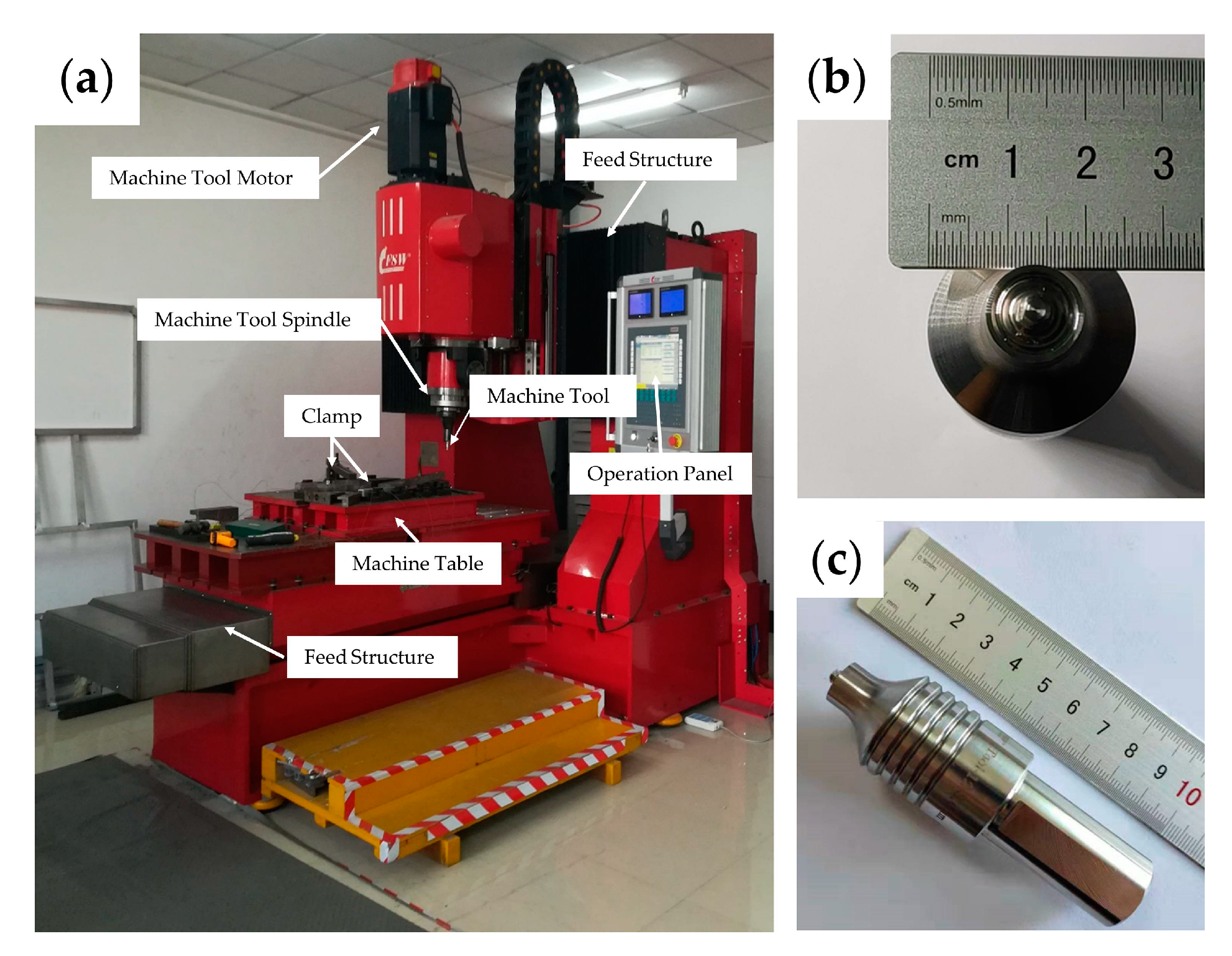
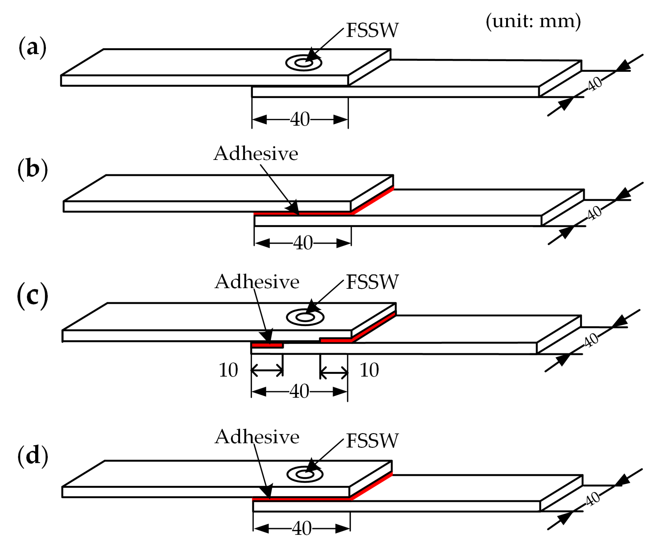
AA6061 aluminum alloy has been widely used in automobile stampings due to its excellent processability and good corrosion resistance. AA6061-T6 coupons of 2 mm thickness were chosen for the present study. Specimens were welded in the lap configuration. The nominal chemical composition was Al-1.1Mg-0.7Si-0.2Cr-0.1Cu-0.1Zn-0.1Mn-0.1Fe for the welding plate. Table 1 illustrates the mechanical properties of the used metal. The individual coupon dimensions of tensile shear were 40 × 110 mm, and were welded on an overlap area of 40 × 40 mm, respectively. Prior to FSSW, the coupons were cleaned with an angle grinder to remove oxide layers on the coupon’s surface. As shown in Figure 2a, welds were produced using a CNC-controlled gantry FSW machine (FSW-LM-AM16, Beijing Seifost Technology Co., Ltd., Beijing, China). The thread FSSW tool is made from high-speed steel (HS6-5-2C) material, having a concave shoulder with a diameter of 12 mm and a probe length of 2.5 mm, as shown in Figure 2b,c. The welding machine was operated in position control mode with plunge speed of 1 mm/s, rotation speed of 1200 rpm and 3 s dwell time. The depth of the shoulder depression was kept constant at 0.3 mm. These parameters were chosen to produce a weld with the largest tensile-shear performance, as documented in previous studies [22,31]. Schematic illustration of the FSSW joint can be seen in Figure 3a.
The adhesive used for the other three types of joints was 3M® DP 420 (3M company, Saint Paul, MN, USA), a typical two-component epoxy adhesive. According to the manufacturer’s recommendation, it takes 48 h at room temperature to achieve complete curing. In AB joint manufacturing, the adhesive was manually applied onto the overlap surfaces. In order to maintain the gap between the plates, two additional 0.2 mm thick plates were placed on both sides of the base metal. Clips applied the pressure on the edges of the joint to overflow the excess adhesive. Finally, samples were cured at room temperature for two days. Figure 3b shows a schematic illustration of an AB specimen.
Two methods were studied for hybrid joints of adhesive and FSSW. The former was called the flow-in (FI) process in which the weld was firstly produced, and the adhesive flowed into the gap between the base metal by capillary action. In the latter, adhesive was applied to the overlap areas before welding, named as the weld-through (WT) process. To ensure the same thickness of the adhesive layers for FI joints, a CNC milling machine (M-V6T, Guangzhou HongLi Co., Ltd., Guangzhou, China) was used to remove 0.2 mm material on coupons. FSSW was performed and the welding parameters were the same as the FSSW process. Then, the adhesive flowed into the gap between the two aluminum plates and completed the curing process. The samples were cured at room temperature for 48 h. The geometries of FI specimen are schematically illustrated in Figure 3c. The WT method was used in the welding bonding process. Before welding, the mixed adhesive was applied on the overlap surfaces. In order to study the effect of welding heat on the WT specimen, three rotation speeds (800, 1200 and 1600 rpm) were selected. The adhesive curing method of FI joints was the same as AB and FI. A schematic illustration of the WT specimen in lap configuration can be seen in Figure 3d.
The mechanical properties of FSSW, AB, FI and WT joints were characterized using lap-shear testing. The specimens were tested on a tensile testing machine (WDW-3100, Jilin Guanteng Automation Technology Co., Ltd., Changchun, China) at a constant cross head speed of 1.5 mm/min. The TSFL (the maximum load in the load–displacement curve) and failure energy (the area under the load–displacement curve) were obtained by averaging the values of three individual specimens [32,33]. Failure modes of FSSW, AB, FI and WT joints were determined by observing the morphology of fracture surfaces. In order to enhance the conductivity of specimens, AB, FI and WT joints were sputter coated with gold nanoparticles. Then, a scanning electron microscope (SEM) (Zeiss EVO 18, Oberkohen, Germany) was used to study the fracture surfaces.
Metallurgical characteristics of the two types of hybrid joint were examined. In order to prevent microstructural changes, specimens were cut along the center line of joints using an arm saw. Then, the samples were embedded in phenolic to expose the center surface of joints. All samples were progressively ground using SiC abrasive paper and polished by a metal sample polishing machine (PG-2D, Shanghai Golden phase Equipment Co., Ltd., Shanghai, China). Finally, the metallographic samples were etched for 25 s by Keller’s reagent (95 mL water, 2.5 mL HNO3, 1.5 mL HCL, 1.0 mL HF). Microstructures were examined using an inverted optical microscopy (OM, Imager-M2M, ZEISS, Oberkohen, Germany).
3. The Finite Element Modelling and Boundary Conditions
During the processing of WT joints, adhesive impurities were introduced into the weld under the rotating action of the welding tool. The welding heat caused carbonization of the adhesive layer near the weld. These factors led to an uneven distribution of WT joint materials. Therefore, this section adopted FEM to analyze the stress distribution of the AB, FSSW and FI joints under tensile loads. Since FI joints include FSSW and AB parts, the methods and results of studying FSSW and AB joints can be referred to the FI joint. According to the symmetry of the model structure, only half of the actual model was created to obtain an optimal model with a short computational time.
3.1. FE Modelling of Spot Weld
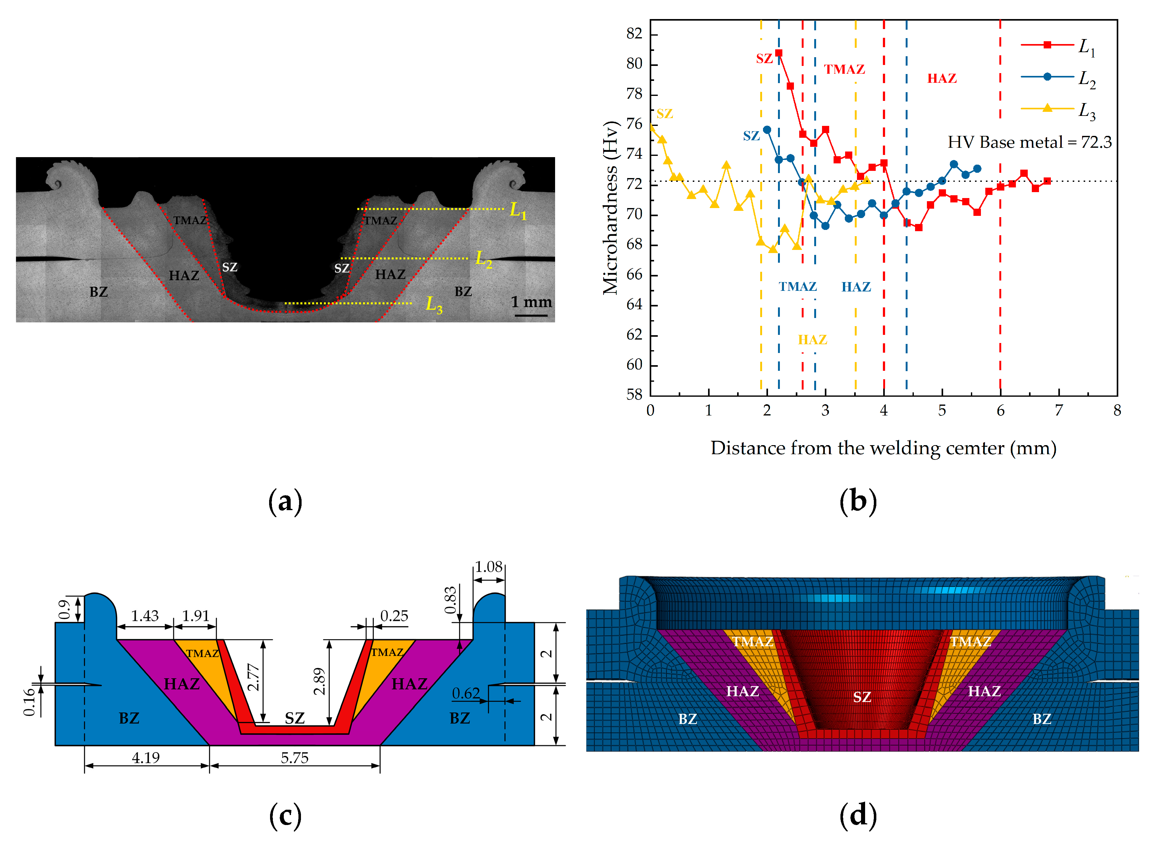
The mechanical behaviors of a weld are determined by the structure and the mechanical properties of the weld regions [34]. The weld formed by the stirring the base material consists of four metallurgical zones: the stirring zone (SZ), thermo-mechanically affected zone (TMAZ), heat-affected zone (HAZ) and base zone (BZ) [8]. As shown in Figure 4a, the approximate boundary among the SZ, TMAZ, HAZ and BZ can be easily identified by the weld microstructure. Figure 4b shows the microhardness distribution of the weld on the three lines (L1, L2, L3). The keyhole defect weakened the load area of the welds. At the same time, the flash edge around the weld caused a complex stress distribution under tensile loads. Besides, there was a gap of about 0.16 mm in the overlap area of the top and bottom plates and a sharp notch was formed. Under tensile loading, stress concentration occurred at the notched tip. Therefore, the microstructure of the weld and the effect of the notch on the stress distribution of the weld were considered in modelling. The dimensions of each weld region were characterized using length–image correlation techniques and the dimensional schematic is shown in Figure 4c. The weld nugget and base material were meshed with eight-node structural solid elements (C3D8R). The size of the elements was refined sufficiently in order to obtain more realistic results. The minimum size of the mesh was 0.15 mm. Overall, 52,473 elements and 60,027 nodes were included in the FE model. Figure 4d depicts the partial weld FE model near the weld nugget of as-welded workpieces. On the other hand, different weld regions have different mechanical properties. In the modelling process, the influence of the mechanical properties of different regions on the simulation results was also considered. The elastoplastic mechanical properties of the weld regions were estimated based on the ratio of the average hardness to the base metal AA 6061-T6, as shown in Table 2 [22,35].
3.2. FE Modelling of Adhesive Layer
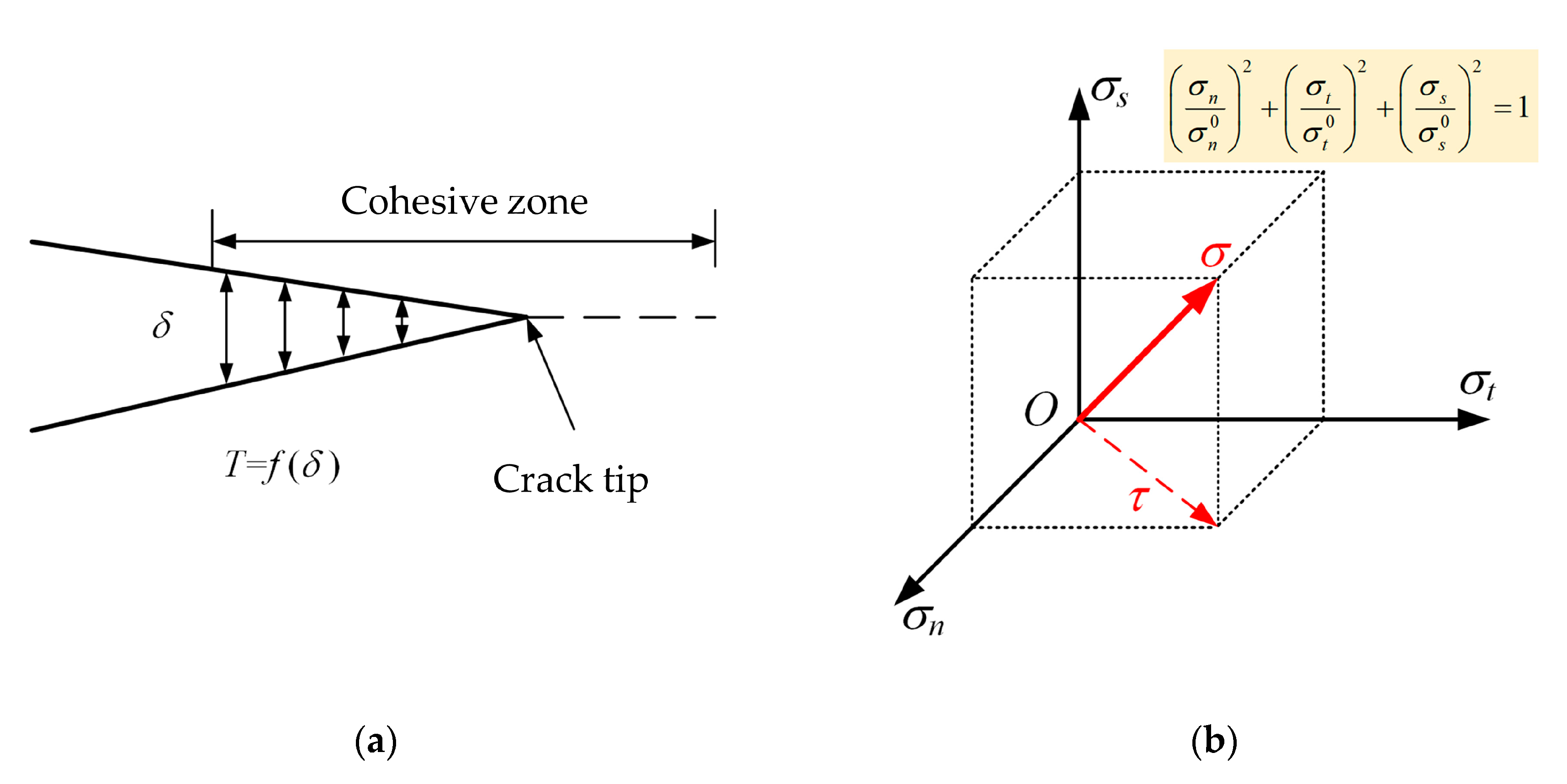
The cohesive zone model (CZM) is a common method for simplified modelling of adhesive layers [37,38,39]. The traction–separation law and liner energetic criterion was used to simulate the mechanical behaviors of cohesive elements [40,41]. The traction and separation model for CZM is shown in Figure 5a, and the relationship between traction force and opening distance is as follows:
where, T and are the traction force and opening distance of the adhesive layer, respectively. The function relation f indicates the constitutive relation of the adhesive.
Elasticity is defined by the constitutive matrix (K), which contains the stiffness parameters and the stresses and strains at the interface,
A suitable approximation for thin adhesive layers is provided with knn = E, ktt = kss = G, knt = kts = ksn = 0 (G is the shear modulus) [41]. When the simulated stress value of the CZM elements reaches the viscous strength, the material softening occurs, resulting in a decrease in material properties [37,42]. The initial damage stress state of CZM can be expressed by:
where, , and are the stress components of cohesive elements in the tensile, shear and tear direction, respectively. , , are maximal values of the corresponding stress components for the considered adhesive. As shown in Figure 5b, the initial damage process occurs when the stress state satisfies Equation (3). The most general criterion for failure of CZM is expressed as the power law (Equation (4)) and depends on the fracture energy of the three pure modes:
where , , are the critical values of the fracture energies of the three pure modes. Gn, Gt and Gs are the fracture energies corresponding to the stress components in three directions of failure elements, respectively. For isotropic adhesive layers, it can be assumed that [43,44].
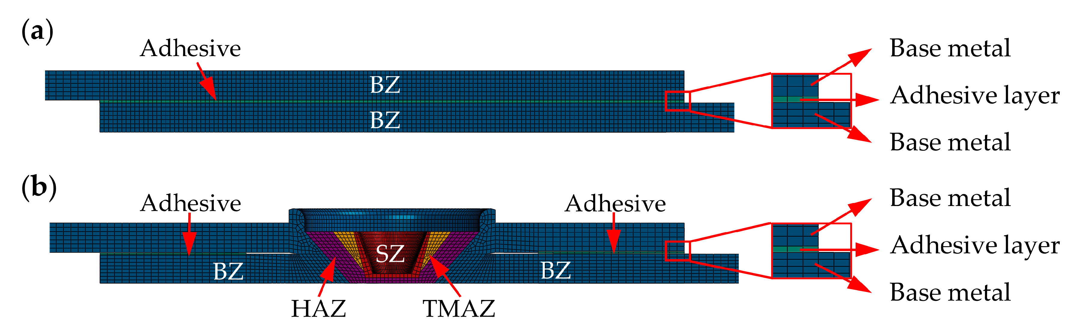
The basic physical and mechanical properties of the used adhesive are given in Table 3. The sheets of AB joint were modelled by 128037 C3D8R solid elements, while the adhesive layer consisted of 8911 cohesive elements of COH3D8. Mesh details at the overlap region of the AB joint in the view of the symmetry plane are shown in Figure 6a. The adhesive layer was connected to the top and bottom sheets using the “Tie” feature of Systèmes® ABAQUS 2016 software. Tie contact is a special interaction model used to define the connection between two bodies, which ensures that the surfaces of the two contacts maintain the same motion and deformation. A similar adhesive layer modelling method was used for the adhesive portion of the FI joint. The cohesive element of 800 COH3D8 was used in the adhesive area and the tie contact model was applied to establish the connection between the adhesive layer and the base material. Mesh details at the overlap region of FI joint are shown in Figure 6b (view of the symmetry plane).
3.3. Load and Boundary Conditions
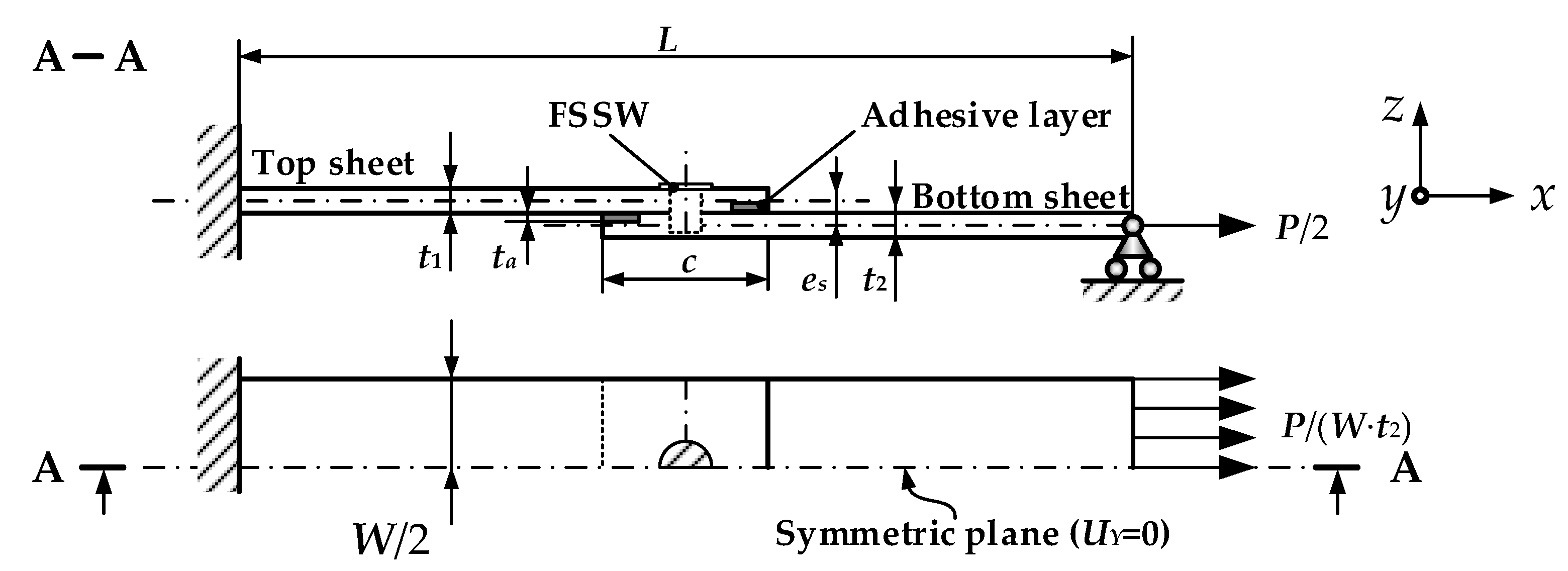
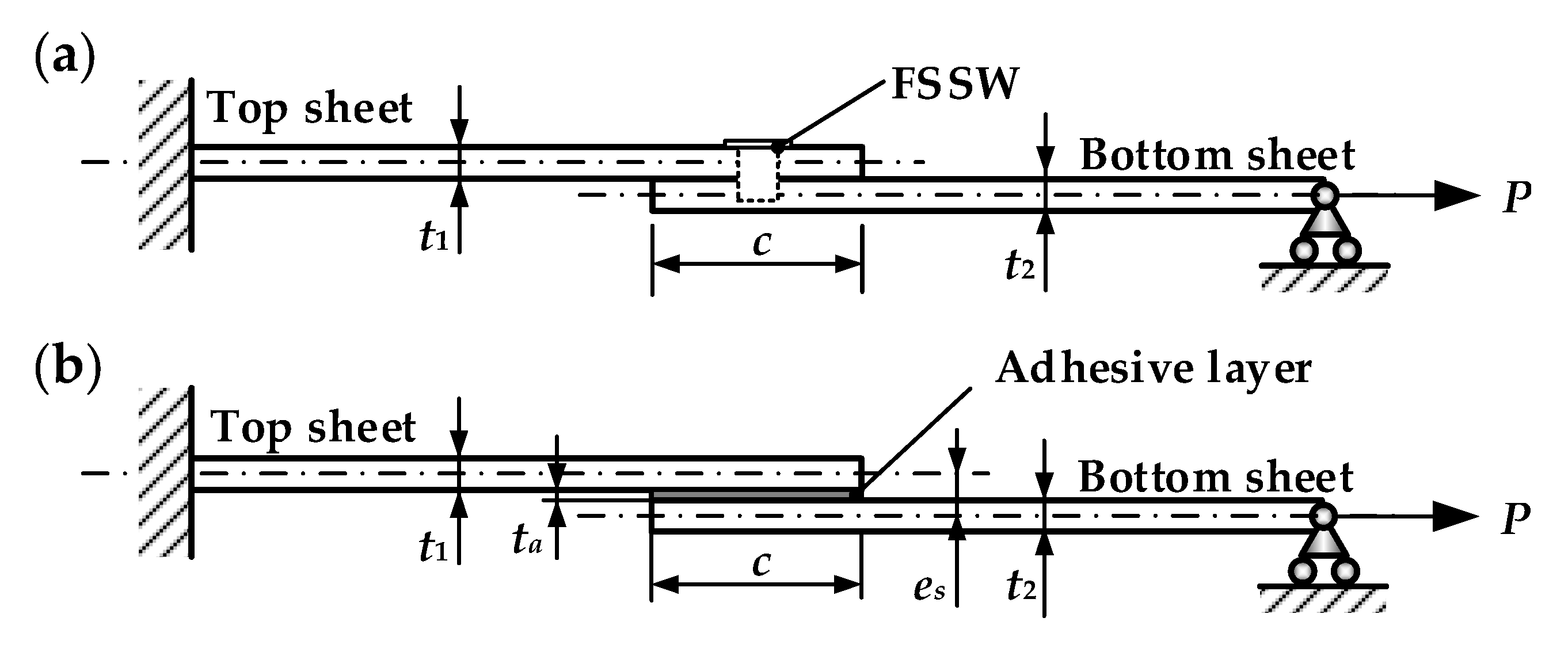
The joint strength of the welded structure and specimen is mainly based on tensile tests of the lap structure. Therefore, a weld-bonded lap joint with a single spot was simulated by using Static, General steps with Nlgeom on. The dimensions and constraints model of the FI joint is shown in Figure 7. Similarly, Figure 8 shows schematics of the loading and constraint conditions of the FSSW and AB joint. Since the specimen was symmetric about the Y-axis, only half of the specimen was considered. The half-model structure was numerically analyzed in the FE model using symmetry constraints on the symmetric plane (UY = 0). The model simulated the tensile process of the joint by fixing one side and applying surface pressure on the other side. The FE model was equated by constraining the displacement in three directions (UX, UY, UZ) at one side of the joint and applying an out-of-face pressure of magnitude P/(W·t2) at the other side.
4. Results and Discussion
4.1. Hybrid Joint Defects
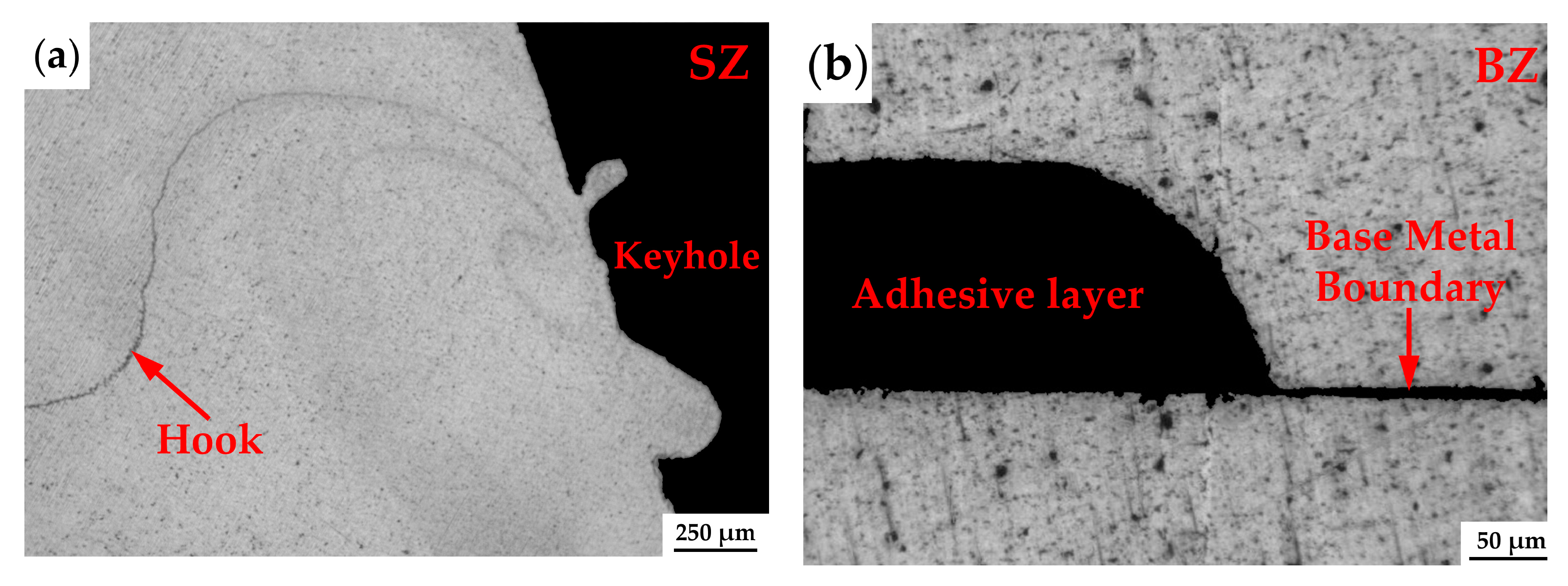
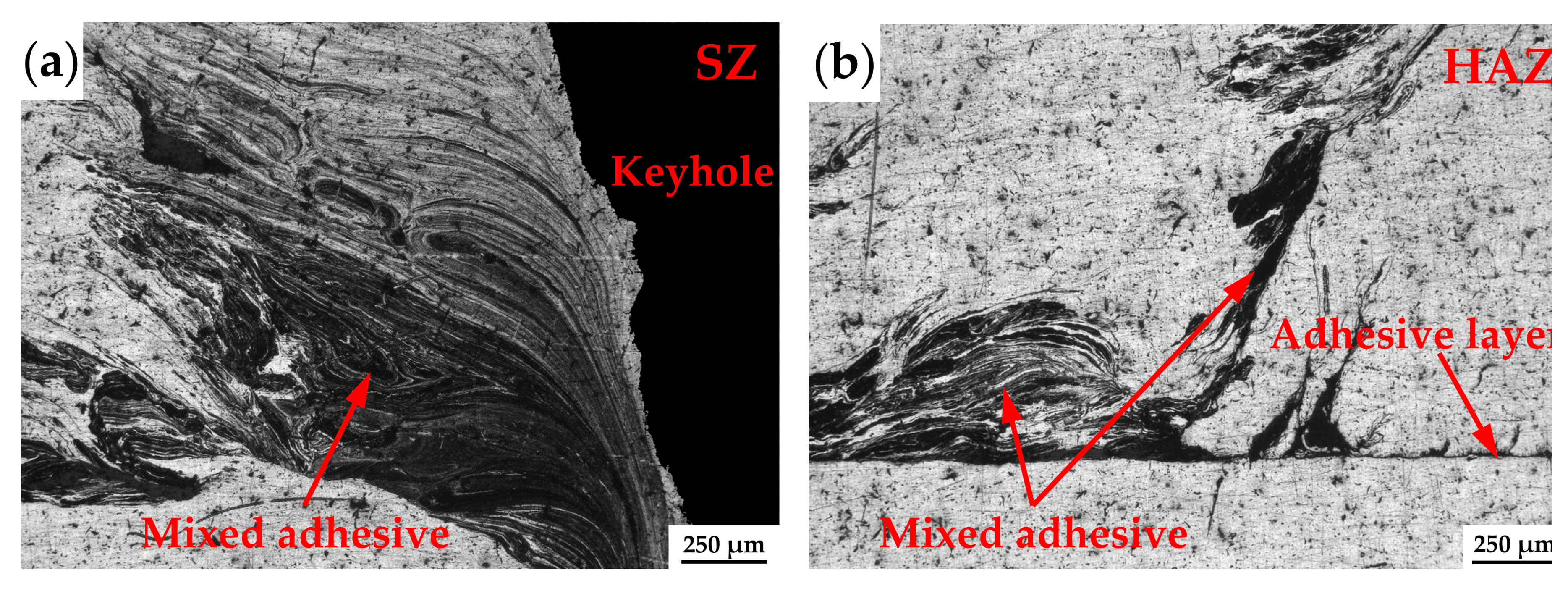
The defects of FI and WT joints in characteristic regions are shown in Figure 9 and Figure 10. Typically, FSSW left a keyhole in the center of the weld after welding, which degraded the mechanical properties of the joint. At the same time, the hook defect appeared in the weld microstructure, which is considered as the starting point for tensile-shear failure of the FSSW weld. Moreover, static tensile-shear strength of the weld is determined by the distance from the keyhole to the hook tip. As the hook height increases, the weld strength decreases [47]. Since the weld and the adhesive layer are separated in the FI joint, hook and keyhole defects were also apparent in the SZ region, as shown in Figure 9a. The two defects have the same weakening effect on FI joints as FSSW welds. In order to ensure consistency in adhesive layer thickness on FI joints, 0.2 mm material was removed by machining. In addition, the adhesive was injected in gap of base metals at the end of the welding process. Figure 9b shows the microstructure of the adhesive region in the FI joint. During the experiment, the adhesive carbonization area of WT joints increased as the tool rotation speed increased from 800 to 1600 rpm. Therefore, the microstructure of WT joints was analyzed at a rotation speed of 800 rpm. Figure 10a exhibits defects in the SZ region of the WT joint. A keyhole appeared in the WT joint, which was similar to the FI joint. Due to the rotational movement of the welding tool, the adhesive mixed with the weld in the regions of SZ and HAZ. The mechanical properties of the weld in WT joints were degraded due to the introduction of adhesive impurities in the weld. Kubit et al. studied the effect of the adhesive layer on the strength of 7075-T6 aluminum alloy refill FSSW joints. The results showed that the adhesive decreased the strength of the welds by 9% to 28% [48].
4.2. Mechanical Properties
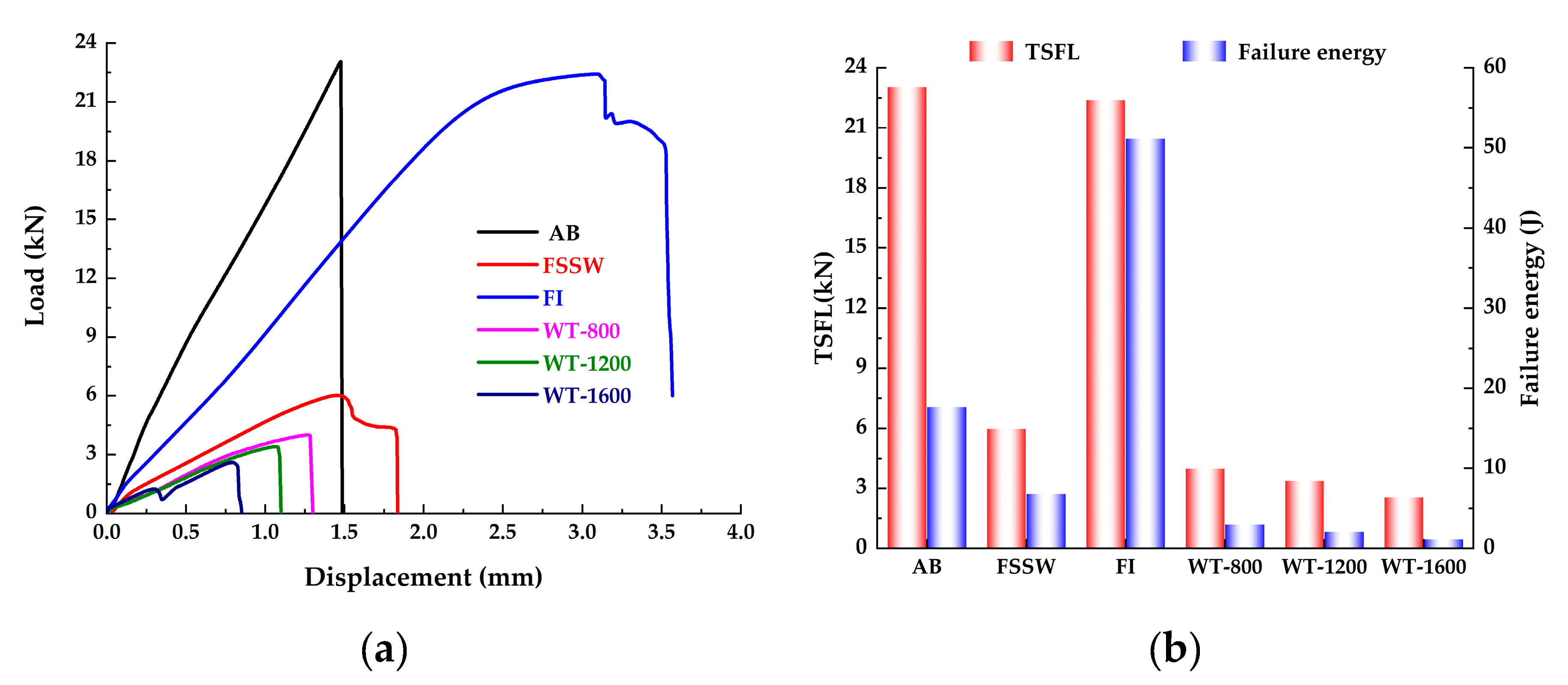
Figure 11a exhibits the load–displacement curves for the FSSW, AB, FI and WT joints, respectively. The TSFL of the AB joint was slightly higher than that of the FI joint, which was in turn higher than that of the FSSW and WT joints. The highest TSFL of the AB joints is due to the uniform distribution of the joint material and the elimination of residual stresses in the joint [26]. The reason for the higher TSFL of FI weld than FSSW weld is that the adhesive layer increases the joint area, resulting in higher load carrying capacity. Compared to the FSSW weld, the adhesive increased the TSFL of FI joints from 5.99 to 22.4 kN and the stiffness from 4439.15 to 9381.4 kN/m. The significantly lower TSFL of WT joints was attributed to adhesive impurities at the weld interface and localized failure of the adhesive near the weld. In addition, when the speed was increased from 800 to 1600 rpm, a larger carbonization area of the adhesive layer occurred due to the higher welding heat, and the TSFL of the WT joint decreased from 3.99 to 2.57 kN. A similar observation of the TSFL of WT joints being lower than the AB joint and welds under the best welding parameters was reported by Amaro et al. for the hybrid joint of FSSW and adhesive [28]. The effect of welding heat on the TSFL of WT joints was also found in [29]. The study showed that the TSFL of WT joints decreased from 30 to 15 kN as the welding time increased from 0 to 6 s.
In order to more completely characterize the tensile-shear characteristics of lap joints, the failure energy was estimated, which was defined as the area under the load–displacement curve [32,33]. Since the failure displacement of the FI weld was significantly higher than that of the AB joint, the failure energy of the AB joint (~17.669 J) was lower than that of the FI joint (~51.14 J). Similar findings were found by Xu et al. They compared the tensile mechanical properties of AB and weld-bonded joints of magnesium–aluminum. When the lap area of the joint was 35 × 35 mm, the failure energy of the weld-bonded joint was significantly higher than that of AB joints [33]. The fracture energy of the FI joint was 8.14 times that of the FSSW weld (~6.828 J) and both of these values were substantially greater than that of the WT joint. Compared to FSSW, the TSFL value and fracture energy of the FI joints increased by 2.7 and 8.14 times, respectively. Clearly, the FI process can significantly improve the connection performances of FSSW.
4.3. Failure Mode
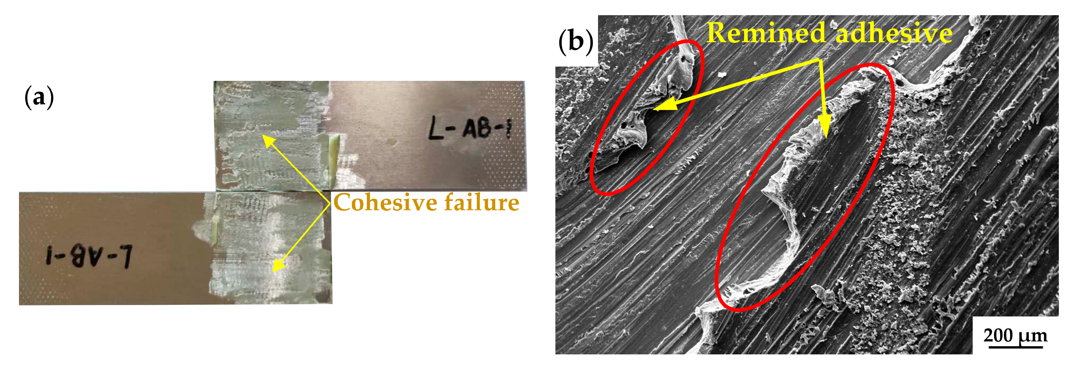
SEM was used to characterize the fracture surface of specimens. Figure 12 shows the SEM micrographs of the fracture surfaces in the AB joint. As can be seen from Figure 12a, the adhesive was uniformly distributed on the top and bottom plates, with a cohesive failure mode. In addition, the joint failure was without obvious deformation, exhibiting brittle fracture characteristics. Figure 12b illustrates the remaining adhesive in the fracture surface of the AB joint. The adhesive fibers were torn into strips under tensile-shear load, as shown in Figure 12c. Due to volume shrinkage during the adhesive layer curing process, microporous defects appeared in the fracture (Figure 12d).
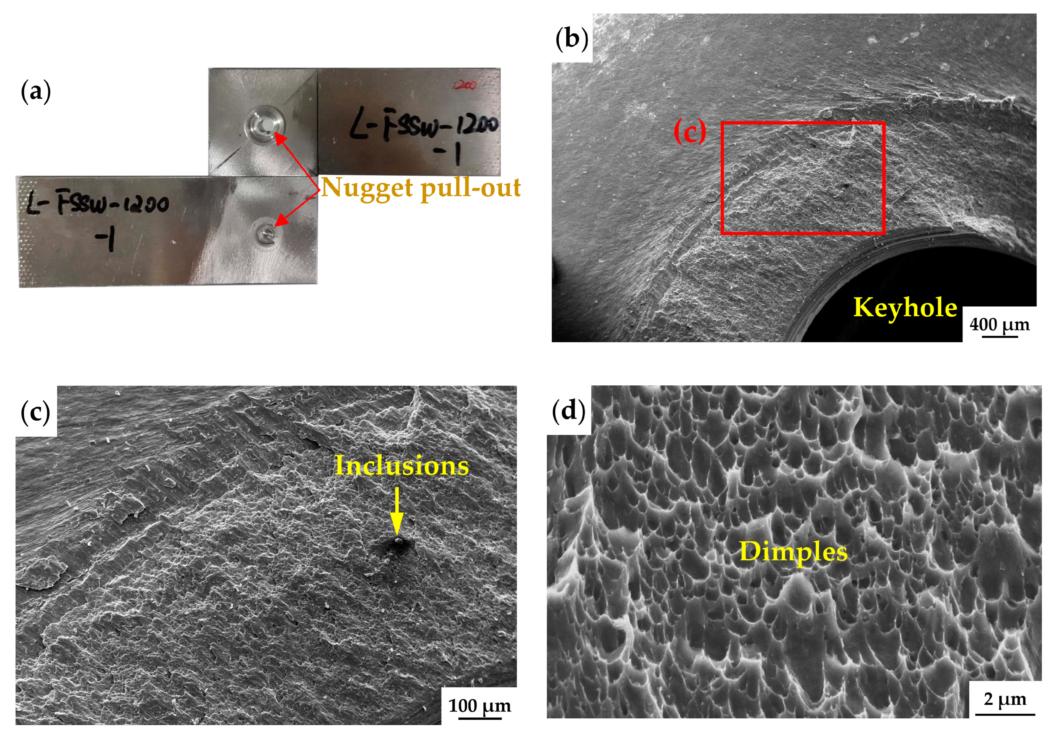
Figure 13 shows macroscopic and SEM images of the tensile fracture surface in the FSSW weld. The weld exhibited a nugget pull-out failure mode (Figure 13a), which tends to exhibit a high tensile strength [49]. Figure 13b displays the SEM photograph of the weld nugget region on the top side of weld. There was a keyhole in the center of the weld that severely weakened the mechanical properties of the joint. In addition, the fracture occurred at the nugget region of the weld. The width of the nugget region is considered a determinant of the weld strength. Figure 13c shows the magnification view in Figure 13b, where the inclusions were precipitated in the weld. These inclusions may be caused by abrasion of the welding tool during the welding process [50]. As can be seen from Figure 13d, the ductile fracture formed due to fracture surface consists of dimples and large craters. Cone-cup type ductile fractures were formed by ductile holes. In addition, round and small-sized cavities can be seen on the fractured surface of the material. This indicates that the failure of the FSSW weld exhibits a ductile fracture.
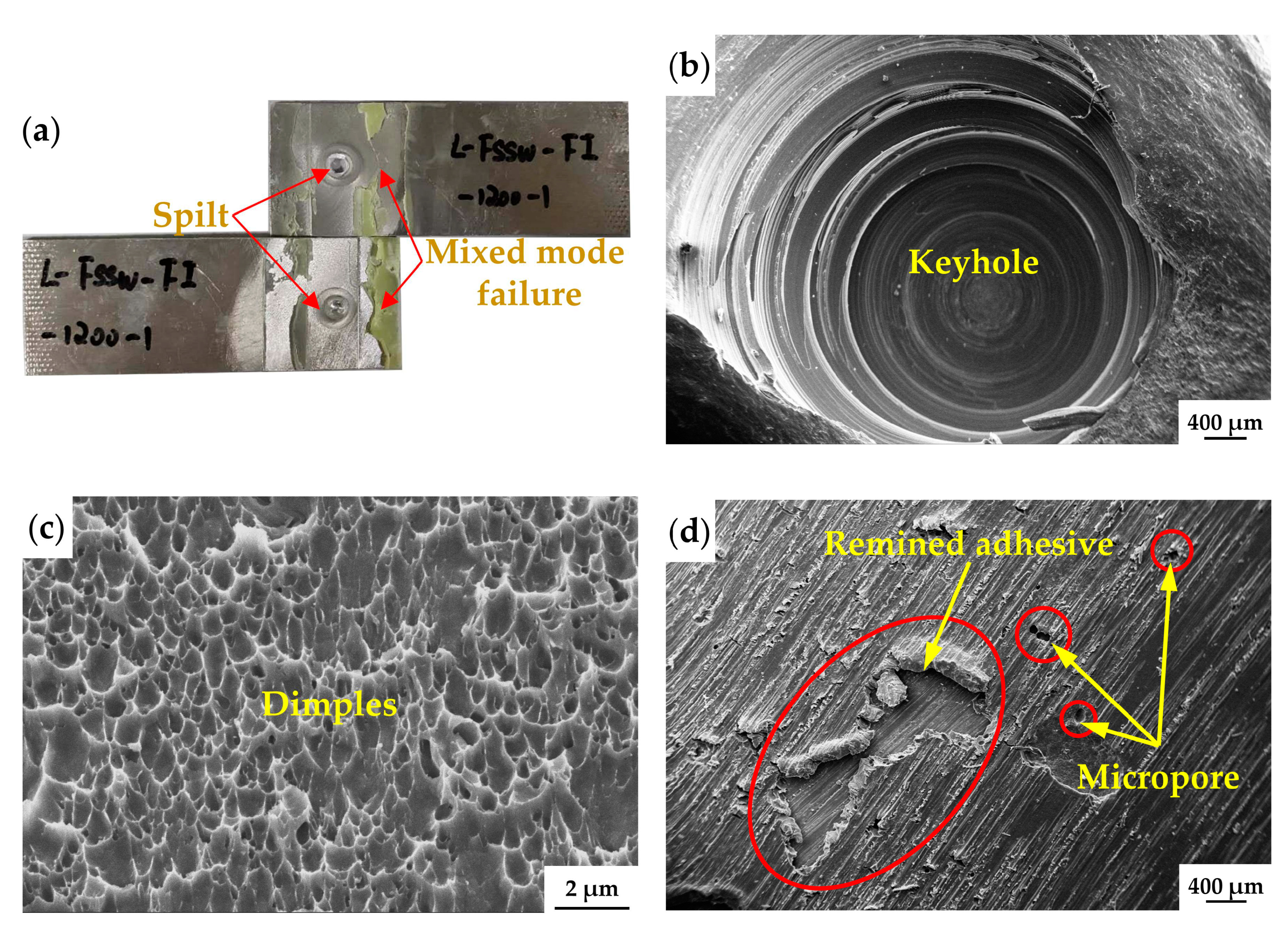
Figure 14a reveals the shear fracture surface of the weld-bond joined by the FI process. The nugget of the weld was diagonally split into two parts and a mixed failure mode appeared in the adhesive area of the FI joint. The failure mode of the weld region in the FI joint differed from that of the single weld joint. The weld showed macroscopic fractures diagonally splitting under high load after the failure of the adhesive layer. The adhesive flowed into the gap between two plates and the thickness of the adhesive layer was not uniform. Under tensile loading, the adhesive region exhibited a mixed failure mode. SEM photographs of FI joints indicate the presence of defects in the weld and adhesive layer areas were similar to those found in a single FSSW and AB joint. Figure 14b illustrates the keyhole defect in the weld area of the FI joint. Figure 14c illustrates that the ductile fractures of the bond area in the weld, due to the failure surface of specimens, consisted of a large number of dimples. The adhesive layer appeared to have adhesive and micropore defects, which was similar to the AB joint, as indicated in Figure 14d.
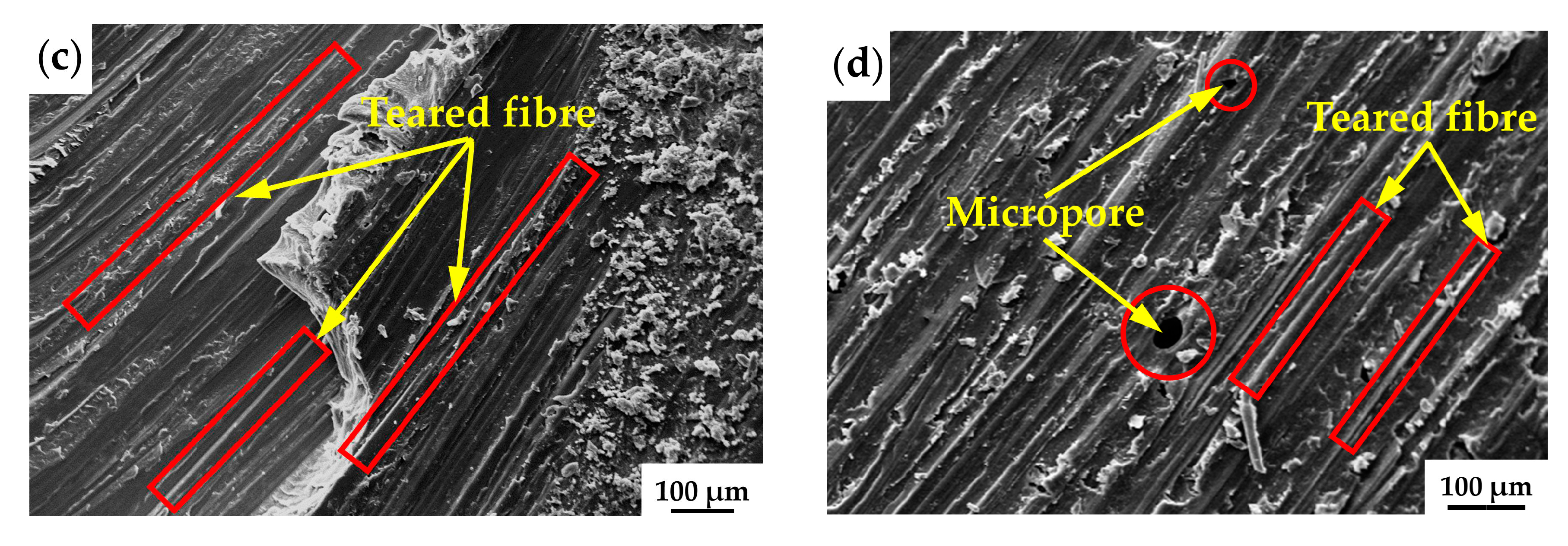
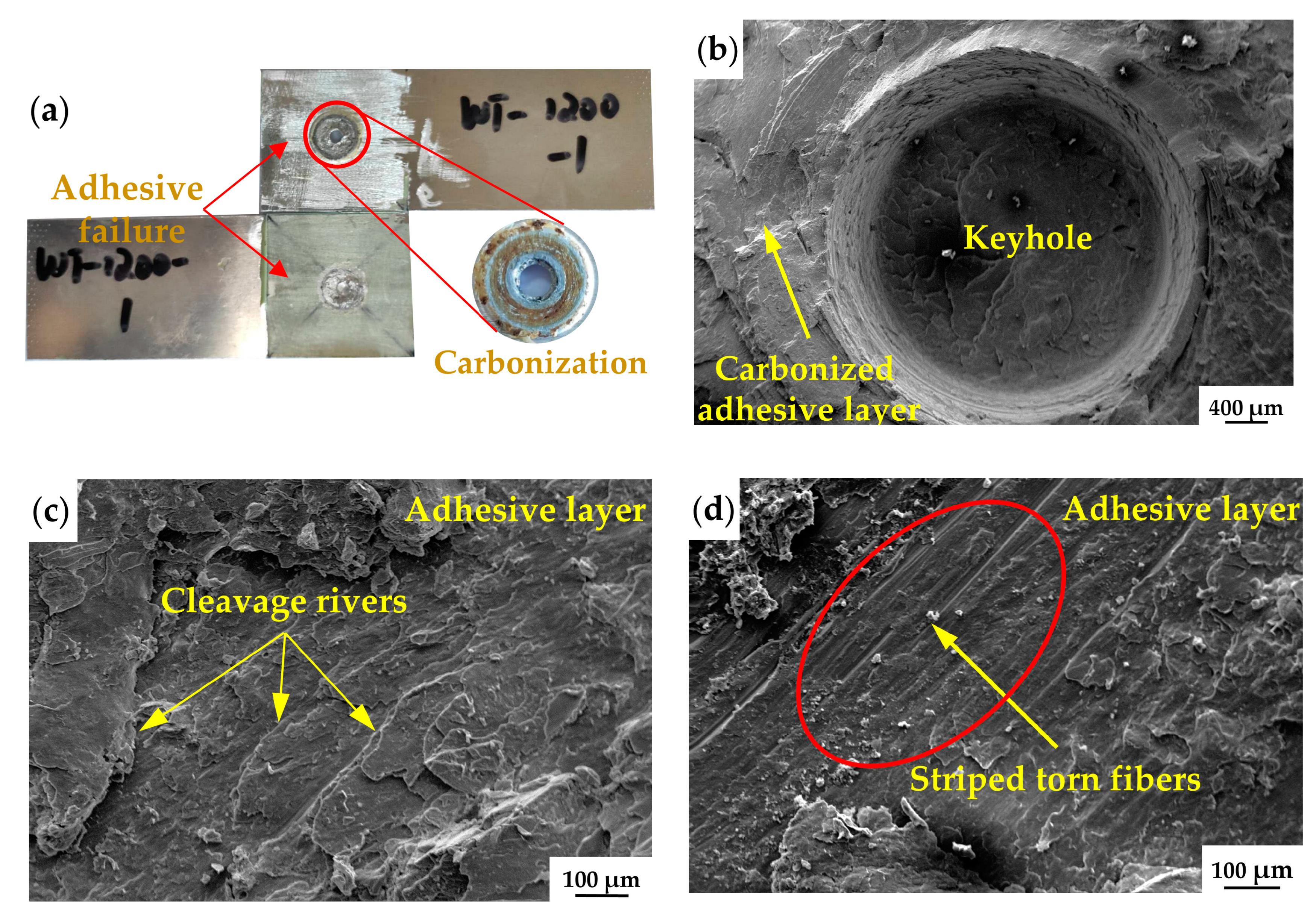
As the rotation speed increases, the TSFL value of WT joints decreases (Figure 11). Therefore, the fracture surface analysis was performed for WT joint with a rotation speed of 800 rpm. As indicated in Figure 15a, the tensile samples of the WT joint were in a cross-nugget failure mode of the weld. In addition, the adhesive layer near the weld was carbonized. The adhesive layer showed cohesive failure on the bottom plate. During the welding process, welding heat caused the adhesive layer near the weld to fail and produce gases. These gases were released through the adhesive layer to the outside of the joint, causing an uneven distribution of the adhesive. Under the tensile load, the adhesive layer of the WT joint exhibited adhesive failure. The keyhole defect also appeared in WT joints and the carbonized adhesive around the weld exhibited cleavage fracture (Figure 15b,c). As the distance from the weld increased, the adhesive partially failed. The adhesive layer cleavage failure and torn fiber damage, coexisted, as shown in Figure 15d.
4.4. Finite Element Stress Analysis of Static Loading
Uneven distribution of the WT joint material was caused by the introduction of adhesive impurities into the weld during the forming process. This does not satisfy the basic assumption of FE analysis. Therefore, this section analyzed the stress distribution under static load for the other three types of joints: AB, FSSW and FI.
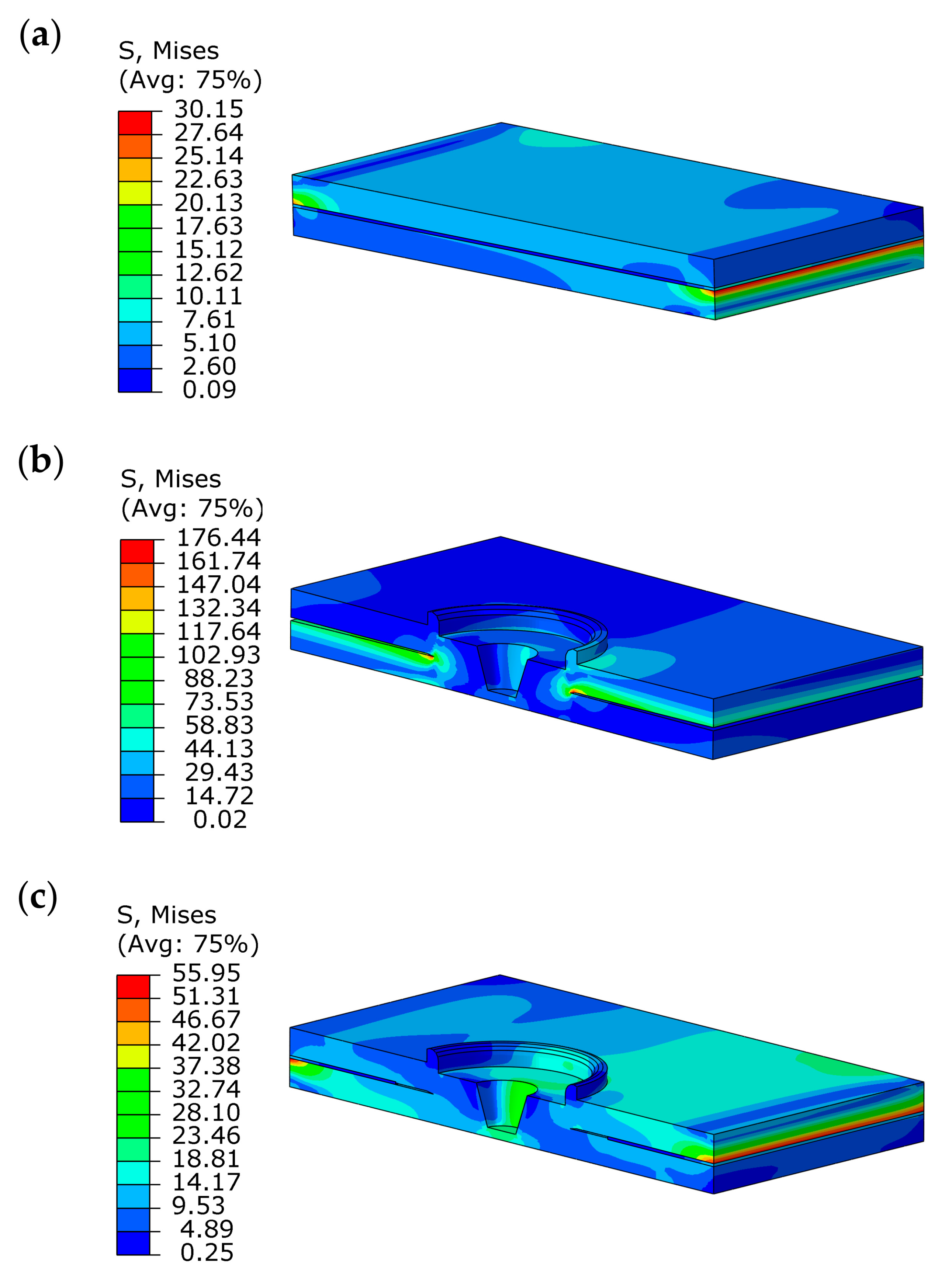
Due to the symmetry of the joints, the FE analysis of the semi-model structure was performed. Figure 16 shows the Mises stresses distribution in the lap area of three types of joint. As shown in Figure 16a, the maximum stress in the AB joint occurred at overlap edges in the tensile direction, with a value of 30.15 MPa. The reason is differential straining between the adherends at the overlap and load asymmetry appear at overlap edges [41]. The adhesive layer far from the edge was in a low stress state. Due to the stress concentration at the edge of the weld nugget, the FSSW joint had the highest equivalent stress among the three types of joints (176.44 MPa), as illustrated in Figure 16b. Application of additional reinforcement of the FSSW weld by an adhesive layer in a single-lap joint decreased the stress level by 68.3% in relation to the FSSW. Similar to the simulation results of the AB joint, the maximum stress in the FI joint also occurred at the edge of the adhesive layer in the tensile direction. In addition, the adhesive layer effectively decreased the stress concentration at the edge of the weld nugget. Similar conclusions were also found by previous researchers. Campilho et al. studied the effect of bond width on stress concentration in the weld nugget of the weld–bond joint. The result shows that the stress concentration in the weld nugget was only present at small lap length (L = 15mm). As the bond width increased, the stress concentration in the weld nugget of the hybrid joint was not obvious [41].
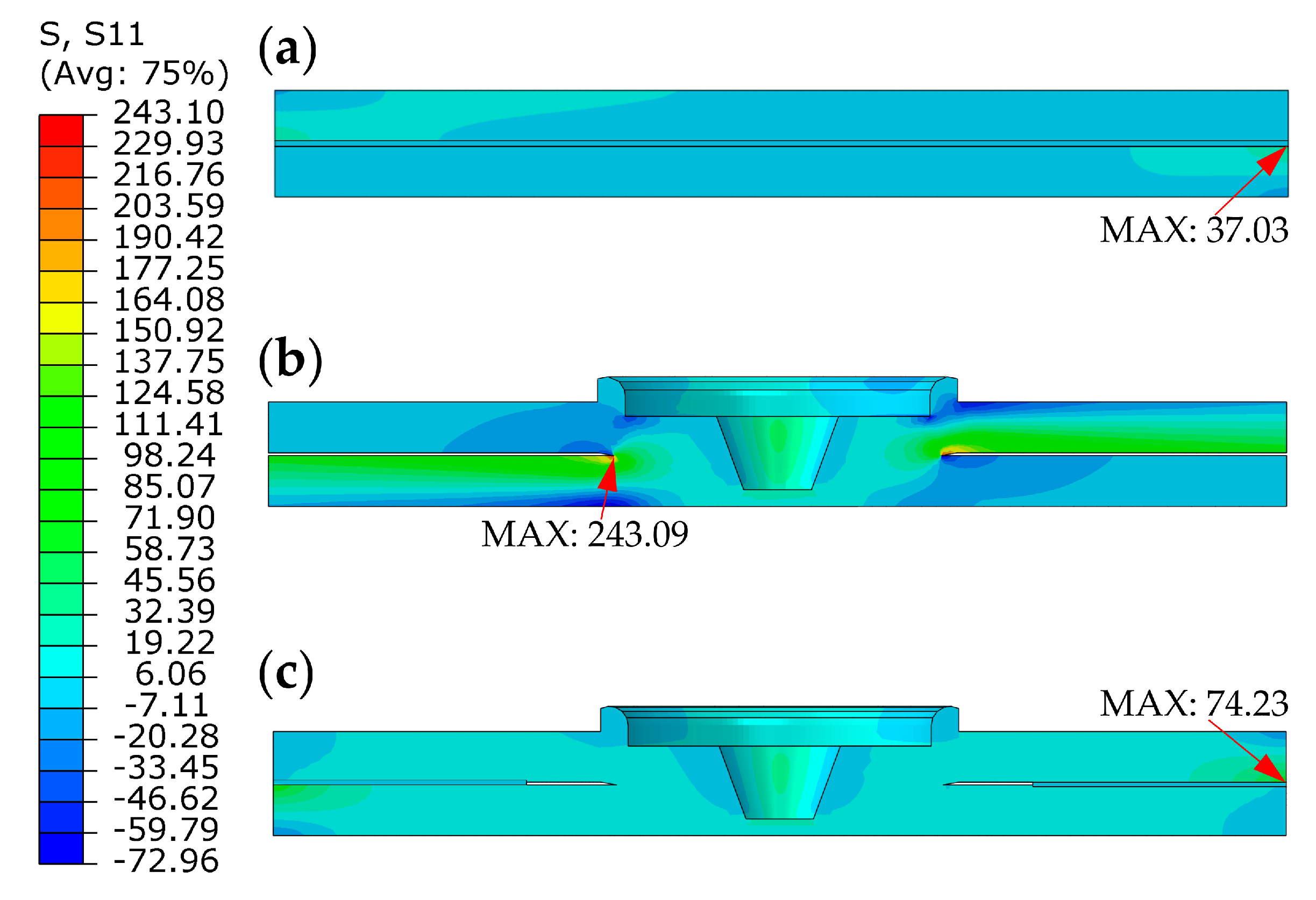
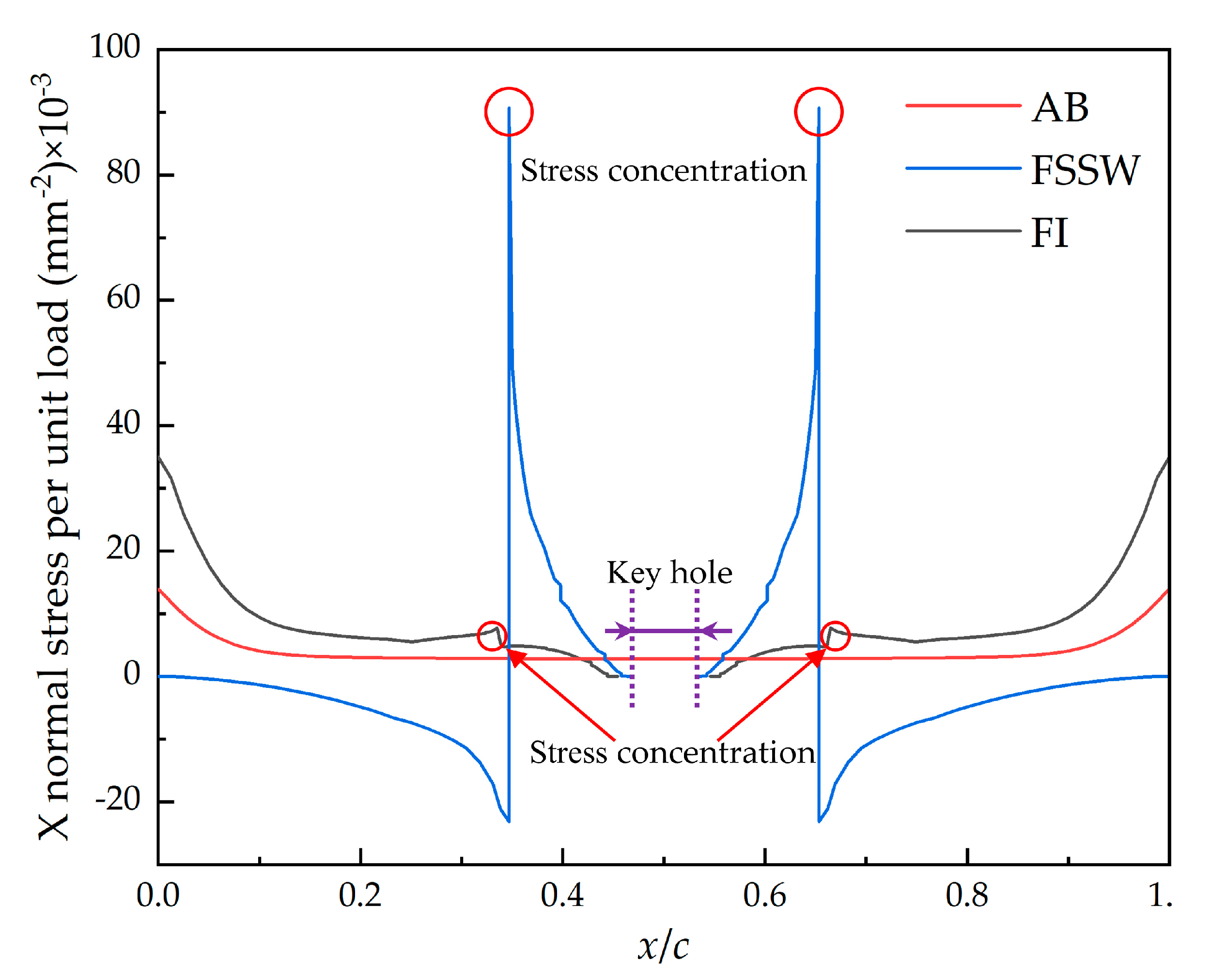
The distribution of X-direction normal stresses in the symmetric plane for three types of joints is shown in Figure 17. Figure 18 shows the variation curve of the stress at the middle layer node with the distance to the lap edge. In all types of joints, the stress was normalized for the same value of load force P. As can be seen from Figure 17, the highest tensile stress among the three types of joint is found in the weld nugget of the FSSW weld, with a value of 243.09 MPa. The maximum stress in the AB and FI joints occurred at the edge of the adhesive layer in the tensile direction, and the stress value in AB joints was lower than in FI. From Figure 18, it can be seen that the tensile stresses at the middle layer nodes show a symmetrical distribution. As the distance to the lap edges increased, the AB and FI stress decreased and a slight rise in the FI joint at the weld nugget occurred. The comparison of Figure 18 shows that the FI process is effective in reducing the stress concentration in the weld. Compared to FSSW joints, the stress at the edge of the weld nugget of FI joints was 15.5 MPa, which was 6% of FSSW. This means the FI process is a good alternative to FSSW and can significantly decrease stress concentrations in the weld.
5. Conclusions
The effect of adhesive on the static tensile-shear mechanical behaviors of FSSW-welded 6061-T6 aluminum alloy was investigated by experiment and numerical simulation. Typical defects of hybrid joints were analyzed. Then, the shear-tension behaviors, failure modes and the stress distribution in the joint lap area were compared. The following conclusions are made:
- In FI joints, weld and adhesive layer were separate. Keyhole and hook defects appeared in the weld zone. The areas of material removed from the base metal were filled with adhesive. In the WT joints, the adhesive layer close to the weld zone was carbonized due to the welding heat. Under the rotating movement of welding tool, the adhesive impurities entered the SZ and HAZ regions of the weld, which degraded the mechanical performances of the WT joints;
- FI joints showed excellent performances in the static tensile-shear test compared to FSSW due to the synergistic effects of the weld and adhesive layer. The weld can block the adhesive crack, and the adhesive can optimize the stress distribution and offer high TSFL values due to the large bonded area. Compared to the FSSW joint, the TSFL value and stiffness of the FI joint were increased by 2.7 and 1.1 times. On the contrary, the WT process weakened the load capacity of the joint. As the rotation speed increased from 800 to 1600 rpm, the TSFL of the WT joint decreased from 3.99 to 2.57 kN;
- Although FI joints exhibited a slightly lower TSFL value than AB joints, due to the higher failure displacements, the energy absorption of the FI joint was 1.89 times higher than that of AB. However, due to internal defects, WT joints displayed the lowest energy absorption among the four types of joint;
- The FI joint presented a hybrid failure mode, which was composed of the cohesive failure within the adhesive layer and the ductile fracture in the weld zone; however, the adhesive closed to the weld zone showed carbonization in WT joints, which exhibited cleavage failure characteristics;
- In FI joints, the adhesive layer decreased the stress concentration in the FSSW weld. FE results show that under 2 kN tensile-shear load, the adhesive reduced the equivalent stress at the joint lap area from 176.44 to 55.95 MPa. Meanwhile, the maximum tensile stress in the FI joint occurred at the edge of the overlap area in the tensile direction. The FI joints reduced the tensile stress at the weld nugget edge from 243.09 to 15.5 MPa;
- In general, the performances of the FI joint are much superior to the FSSW joint. Moreover, the use of the FI process for aluminum alloy connection is strongly recommended, especially in crucial structure areas.
Author Contributions
Conceptualization, G.Y. and B.Z.; data curation, G.Y. and L.Y.; funding acquisition, X.C.; investigation, G.Y.; methodology, G.Y. and X.C.; project administration, X.C. and K.P.; writing—original draft, G.Y.; writing—review & editing, X.C. All authors have read and agreed to the published version of the manuscript.
Funding
This research was financially funded by the National Key Research and Development Plan of China (Grant No. 2016YFB0101601-7) and Jilin Province School Co-construction Project (Grant No. SXGJSF2017-2-1-5).
Acknowledgments
The authors acknowledge the use of the facilities within the State Key Laboratory of Automobile Simulation and Control of Jilin University and the Changchun University of Technology.
Conflicts of Interest
The authors declare no conflict of interest.
References
- Stohl, A.; Aamaas, B.; Amann, M.; Baker, L.H.; Bellouin, N.; Berntsen, T.K.; Boucher, O.; Cherian, R.; Collins, W.; Daskalakis, N.; et al. Evaluating the Climate and Air Quality Impacts of Short-Lived Pollutants. Atmos. Chem. Phys. 2015, 15, 10529–10566. [Google Scholar] [CrossRef] [Green Version]
- Fragkos, P.; Tasios, N.; Paroussos, L.; Capros, P.; Tsani, S. Energy System Impacts and Policy Implications of the European Intended Nationally Determined Contribution and Low-Carbon Pathway to 2050. Energy Policy 2017, 100, 216–226. [Google Scholar] [CrossRef]
- Rao, G.A.; Ramanaiah, N. Dissimilar Metals AISI 304 Steel and AA 2219 Aluminium Alloy Joining by Friction Welding Method. Mater. Today Proc. 2019, 19, 902–907. [Google Scholar] [CrossRef]
- Lehmann, A.; Berger, M.; Finkbeiner, M. Life Cycle Based CO2 Emission Credits: Options for Improving the Efficiency and Effectiveness of Current Tailpipe Emissions Regulation in the Automotive Industry. J. Ind. Ecol. 2018, 22, 1066–1079. [Google Scholar] [CrossRef] [Green Version]
- Kayode, O.; Akinlabi, E.T. An Overview on Joining of Aluminium and Magnesium Alloys Using Friction Stir Welding (FSW) for Automotive Lightweight Applications. Mater. Res. Express 2019, 6, 112005. [Google Scholar] [CrossRef]
- Dragatogiannis, D.A.; Kollaros, D.; Karakizis, P.; Pantelis, D.; Lin, J.; Charitidis, C. Friction Stir Welding between 6082 and 7075 Aluminum Alloys Thermal Treated for Automotive Applications. Mater. Perform. Charact. 2019, 8, 571–589. [Google Scholar] [CrossRef]
- Blatnicky, M.; Saga, M.; Dizo, J.; Bruna, M. Application of Light Metal Alloy EN AW 6063 to Vehicle Frame Construction with an Innovated Steering Mechanism. Materials 2020, 13, 817. [Google Scholar] [CrossRef] [Green Version]
- Kluz, R.; Kubit, A.; Trzepiecinski, T.; Faes, K. Polyoptimisation of the Refill Friction Stir Spot Welding Parameters Applied in Joining 7075-T6 Alclad Aluminium Alloy Sheets Used in Aircraft Components. Int. J. Adv. Manuf. Technol. 2019, 103, 3443–3457. [Google Scholar] [CrossRef] [Green Version]
- Castro, C.D.C.; Plaine, A.H.; Alcantara, N.G.D.; Santos, J.F.D. Taguchi Approach for the Optimization of Refill Friction Stir Spot Welding Parameters for AA2198-T8 Aluminum Alloy. Int. J. Adv. Manuf. Technol. 2018, 99, 1927–1936. [Google Scholar] [CrossRef]
- Lin, C.W.; Hung, F.Y.; Lui, T.S.; Chen, L.H. Weibull Statistics of Tensile-Shear Strength of 5083 Aluminum Alloy after Friction Stir Spot Welding. Mater. Trans. 2015, 56, 54–60. [Google Scholar] [CrossRef] [Green Version]
- Shen, Z.; Ding, Y.; Gerlich, A.P. Advances in Friction Stir Spot Welding. Crit. Rev. Solid State Mater. Sci. 2019, 1–78. [Google Scholar] [CrossRef]
- Chen, K.; Liu, X.; Ni, J. A Review of Friction Stir-Based Processes for Joining Dissimilar Materials. Int. J. Adv. Manuf. Technol. 2019, 104, 1709–1731. [Google Scholar] [CrossRef]
- Thomas, W.M.; Nicholas, E.D.; Needham, J.C.; Murch, M.G.; Templesmith, P.; Dawes, C.J. Friction Stir Welding. GB Patent Application No. 9125978.8, 6 December 1991. [Google Scholar]
- Jamili-Shirvan, Z.; Haddad-Sabzevar, M.; Vahdati-Khaki, J.; Yao, K.F. Mechanical and Thermal Properties of Identified Zones at a Ti-Based Bulk Metallic Glass Weld Spot Jointed by Friction Stir Spot Welding (FSSW). J. Non-Cryst. Solids 1201, 88. [Google Scholar] [CrossRef]
- Lambiase, F.; Paoletti, A.; Ilio, A.D. Friction Spot Stir Welding of Polymers: Control of Plunging Force. Int. J. Adv. Manuf. Technol. 2017, 90, 2827–2837. [Google Scholar] [CrossRef]
- Li, M.; Zhang, C.; Wang, D.; Zhou, L.; Wellmann, D.; Tian, Y. Friction Stir Spot Welding of Aluminum and Copper: A Review. Materials 2020, 13, 156. [Google Scholar] [CrossRef] [PubMed] [Green Version]
- Adibeig, M.R.; Marami, G.; Saeimi-Sadigh, M.A.; da Silva, L.F.M. Experimental and Numerical Study of Polyethylene Hybrid Joints: Friction Stir Spot Welded Joints Reinforced with Adhesive. Int. J. Adhes. 2020, 98, 102555. [Google Scholar] [CrossRef]
- Jedrasiak, P.; Shercliff, H.R. Small Strain Finite Element Modelling of Friction Stir Spot Welding of Al and Mg Alloys. J. Mater. Process. Technol. 2019, 263, 207–222. [Google Scholar] [CrossRef]
- Abdullah, I.T.; Hussein, S.K. Improving the Joint Strength of the Friction Stir Spot Welding of Carbon Steel and Copper Using the Design of Experiments Method. Multidiscip. Model. Mater. Struct. 2018, 14, 908–922. [Google Scholar] [CrossRef]
- Abbass, M.K.; Hussein, S.K.; Khudhair, A.A. Optimization of Mechanical Properties of Friction Stir Spot Welded Joints for Dissimilar Aluminum Alloys (AA2024-T3 and AA 5754-H114). Arab. J. Sci. Eng. 2016, 41, 4563–4572. [Google Scholar] [CrossRef] [Green Version]
- Bozkurt, Y.; Salman, S.; Cam, G. Effect of Welding Parameters on Lap Shear Tensile Properties of Dissimilar Friction Stir Spot Welded AA 5754-H22/2024-T3 Joints. Sci. Technol. Weld. Join. 2013, 18, 337–345. [Google Scholar] [CrossRef]
- Zhang, B.; Chen, X.; Pan, K.; Li, M.; Wang, J. Thermo-Mechanical Simulation Using Microstructure-Based Modeling of Friction Stir Spot Welded AA 6061-T6. J. Manuf. Process. 2019, 37, 71–81. [Google Scholar] [CrossRef]
- Costa, H.R.; Reis, J.M.; Souza, J.P.; Pacheco, P.M.; Aguiar, R.A.; Barros, S.D. Experimental Investigation of the Mechanical Behaviour of Spot Welding–Adhesives Joints. Compos. Struct. 2015, 133, 847–852. [Google Scholar] [CrossRef]
- Darwish, S.M. Science of Weld: Adhesive Joints. In Hybrid Adhesive Joints; Springer: Heidelberg, Germany, 2010; pp. 1–36. [Google Scholar]
- Samhan, A.M.A. Analysis of T-Peel Weld-Bonded Joint with Single Overlap Support. Adv. Mater. Res. 2011, 194, 2276–2283. [Google Scholar] [CrossRef]
- Pouranvari, M.; Safikhani, E. Mechanical Properties of Martensitic Stainless Steel Weld/Adhesive Hybrid Bonds. Sci. Technol. Weld. Join. 2018, 23, 227–233. [Google Scholar] [CrossRef]
- Ren, D.; Liu, L.; Li, Y. Investigation on Overlap Joining of AZ61 Magnesium Alloy: Laser Welding, Adhesive Bonding, and Laser Weld Bonding. Int. J. Adv. Manuf. Technol. 2012, 61, 195–204. [Google Scholar] [CrossRef]
- Amaro, A.M.; Reis, P.N.B. Loureiro, A. Effect of Friction-Stir Weld Parameters on Hybrid Bonded Joints. J. Adhes. 2020, 1–17. [Google Scholar] [CrossRef]
- Hatzky, M.; Frank, A.; Boehm, S. Friction Stir Spot Welding with Additional Bonding of Thick Sheet Aluminum Joints. Metals 2019, 9, 732. [Google Scholar] [CrossRef] [Green Version]
- Babu, S.; Sankar, V.S.; Ram, G.D.J.; Venkitakrishnan, P.V.; Reddy, G.M.; Rao, K.P. Microstructures and Mechanical Properties of Friction Stir Spot Welded Aluminum Alloy AA2014. J. Mater. Eng. Perform. 2013, 22, 71–84. [Google Scholar] [CrossRef]
- Garg, A.; Bhattacharya, A. On Lap Shear Strength of Friction Stir Spot Welded AA6061 Alloy. J. Manuf. Process. 2017, 26, 203–215. [Google Scholar] [CrossRef]
- Chowdhury, S.H.; Chen, D.L.; Bhole, S.D.; Cao, X.; Wanjara, P. Lap Shear Strength and Fatigue Behavior of Friction Stir Spot Welded Dissimilar Magnesium-to-Aluminum Joints with Adhesive. Mater. Sci. Eng. A Struct. Mater. Prop. Microstruct. Process. 2013, 562, 53–60. [Google Scholar] [CrossRef]
- Xu, W.; Liu, L.; Zhou, Y.; Mori, H.; Chen, D. Tensile and Fatigue Properties of Weld-Bonded and Adhesive-Bonded Magnesium Alloy Joints. Mater. Sci. Eng. A 2013, 563, 125–132. [Google Scholar] [CrossRef]
- Zhang, B.; Chen, X.; Pan, K.; Yang, C. J-Integral Based Correlation Evaluation between Microstructure and Mechanical Strength for FSSW Joints Made of Automotive Aluminum Alloys. J. Manuf. Process. 2019, 44, 62–71. [Google Scholar] [CrossRef]
- Fanelli, P.; Vivio, F.; Vullo, V. Experimental and Numerical Characterization of Friction Stir Spot Welded Joints. Eng. Fract. Mech. 2012, 81, 17–25. [Google Scholar] [CrossRef]
- Yang, S.; Sun, L.; Deng, H.; Li, G.; Cui, J. A Modified Johnson-Cook Model of AA6061-O Aluminum Alloy with Quasi-Static Pre-Strain at High Strain Rates. Int. J. Mater. Form. 2020, 1–13. [Google Scholar] [CrossRef]
- Li, Y.; Yang, Y.; Li, J.; Wang, B.; Liao, Y. Experimental-Numerical Analysis of Failure of Adhesively Bonded Lap Joints under Transverse Impact and Different Temperatures. Int. J. Impact Eng. 2020, 140, 103541. [Google Scholar] [CrossRef]
- Dadian, A.; Rahnama, S.; Zolfaghari, A. Experimental Study of the CTBN Effect on Mechanical Properties and Mode I and II Fracture Toughness of a New Epoxy Resin. J. Adhes. Sci. Technol. 2020, 1–16. [Google Scholar] [CrossRef]
- Ahangarnazhad, B.H.; Pourbaba, M.; Afkar, A. Bond Behavior between Steel and Glass Fiber Reinforced Polymer (GFRP) Bars and Ultra High Performance Concrete Reinforced by Multi-Walled Carbon Nanotube (MWCNT). Steel Compos. Struct. 2020, 35, 463–474. [Google Scholar] [CrossRef]
- Anyfantis, K.N.; Tsouvalis, N.G. A Novel Traction–Separation Law for the Prediction of the Mixed Mode Response of Ductile Adhesive Joints. Int. J. Solids Struct. 2012, 49, 213–226. [Google Scholar] [CrossRef] [Green Version]
- Campilho, R.; Pinto, A.; Banea, M.D.; da Silva, L.F. Optimization Study of Hybrid Spot-Welded/Bonded Single-Lap Joints. Int. J. Adhes. Adhes. 2012, 37, 86–95. [Google Scholar] [CrossRef] [Green Version]
- Jaillon, A.; Jumel, J.; Lachaud, F.; Paroissien, E. Mode I Cohesive Zone Model Parameters Identification and Comparison of Measurement Techniques Based on Uncertainty Estimation. Int. J. Solids Struct. 2020, 191, 577–587. [Google Scholar] [CrossRef]
- Manual, D.S. ABAQUS 2016 HTML Documentation. Available online: http://130.149.89.49:2080/v2016/index.html (accessed on 10 June 2020).
- Sadowski, T.; Golewski, P.; Kneć, M. Experimental Investigation and Numerical Modelling of Spot Welding–Adhesive Joints Response. Compos. Struct. 2014, 112, 66–77. [Google Scholar] [CrossRef]
- Hortnagl, J.G. Determination of Cohesive Parameters for Aerospace Adhesives. Master’s Thesis, Oregon State University, Corvallis, OR, USA, 2013. [Google Scholar]
- Zhang, Z.; Shang, J.; Lawrence Jr, F. A Backface Strain Technique for Detecting Fatigue Crack Initiation in Adhesive Joints. J. Adhes. 1995, 49, 23–36. [Google Scholar] [CrossRef]
- Fernandes, C.A.; Filho, S.L.U.; Suhuddin, U.; Santos, J.F.D. Effects of Geometrical Feature on Microstructures and Mechanical Properties of Refill Friction Stir Spot Welding 6061 Aluminum Alloy. Mater. Res. Ibero Am. J. Mater. 2019, 22, 1–5. [Google Scholar] [CrossRef]
- Kubit, A.; Wydrzynski, D.; Trzepiecinski, T. Refill Friction Stir Spot Welding of 7075-T6 Aluminium Alloy Single-Lap Joints with Polymer Sealant Interlayer. Compos. Struct. 2018, 201, 389–397. [Google Scholar] [CrossRef]
- Barlas, Z. Effect of Friction Stir Spot Weld Parameters on Cu/Cuzn30 Bimetal Joints. Int. J. Adv. Manuf. Technol. 2015, 80, 161–170. [Google Scholar] [CrossRef]
- Sanusi, K.O.; Akinlabi, E.T.; Muzenda, E.; Akinlabi, S.A. Enhancement of Corrosion Resistance Behaviour of Frictional Stir Spot Welding of Copper. Mater. Today Proc. 2015, 2, 1157–1165. [Google Scholar] [CrossRef]
Figure 1.
Schematic cross-sectional view of a friction stir spot welding (FSSW) weld, reproduced from [30], with permission from Springer Nature, 2020.
Figure 1.
Schematic cross-sectional view of a friction stir spot welding (FSSW) weld, reproduced from [30], with permission from Springer Nature, 2020.

Figure 2.
Physical pictures of the process equipment: (a) FSSW portal system; (b) and (c) welding tool.
Figure 2.
Physical pictures of the process equipment: (a) FSSW portal system; (b) and (c) welding tool.

Figure 3.
Schematic illustration of four types of joint: (a) FSSW; (b) Adhesive bonding (AB); (c) Flow-in (FI); (d) Weld-through (WT).
Figure 3.
Schematic illustration of four types of joint: (a) FSSW; (b) Adhesive bonding (AB); (c) Flow-in (FI); (d) Weld-through (WT).

Figure 4.
(a) Microstructure and feature regions of the weld; (b) Microhardness distribution on three lines (L1, L2 and L3); (c) Geometry and characteristic dimensions of the weld nugget (mm); (d) Mesh details for the weld (view of the symmetry plane).
Figure 4.
(a) Microstructure and feature regions of the weld; (b) Microhardness distribution on three lines (L1, L2 and L3); (c) Geometry and characteristic dimensions of the weld nugget (mm); (d) Mesh details for the weld (view of the symmetry plane).

Figure 5.
(a) Traction-separation model for the cohesive zone model (CZM); (b) Schematic diagram of damage initiation criterion for cohesive elements.
Figure 5.
(a) Traction-separation model for the cohesive zone model (CZM); (b) Schematic diagram of damage initiation criterion for cohesive elements.

Figure 6.
Mesh details at the overlap region (view of the symmetry plane): (a) AB; (b) FI.

Figure 7.
The geometry and boundary conditions model of the FI joint (t1 = t2 = 2 mm, ta = 0.2 mm, es = 2.2 mm, L = 180 mm, P = 2 kN, W = c = 40 mm).
Figure 7.
The geometry and boundary conditions model of the FI joint (t1 = t2 = 2 mm, ta = 0.2 mm, es = 2.2 mm, L = 180 mm, P = 2 kN, W = c = 40 mm).

Figure 8.
Geometry and boundary conditions model: (a) FSSW; (b) AB.

Figure 9.
Welding defects in characteristic regions of the FI joint: (a) Stirring zone (SZ) of the weld; (b) Adhesive layer area.
Figure 9.
Welding defects in characteristic regions of the FI joint: (a) Stirring zone (SZ) of the weld; (b) Adhesive layer area.

Figure 10.
Welding defects in characteristic regions of the WT joint: (a) SZ; (b) Heat-affected zone (HAZ).
Figure 10.
Welding defects in characteristic regions of the WT joint: (a) SZ; (b) Heat-affected zone (HAZ).

Figure 11.
Tensile-shear mechanical behaviors of four types of joint: (a) Load–displacement curves; (b) Bar chart of tensile-shear failure load (TSFL) and failure energy.
Figure 11.
Tensile-shear mechanical behaviors of four types of joint: (a) Load–displacement curves; (b) Bar chart of tensile-shear failure load (TSFL) and failure energy.

Figure 12.
Typical macroscopic and SEM images of the fracture surface in the AB joint: (a) Physical diagram of joint fracture; (b) Remaining adhesive area; (c) Magnification view in (b); (d) Micropore defect in adhesive layer.
Figure 12.
Typical macroscopic and SEM images of the fracture surface in the AB joint: (a) Physical diagram of joint fracture; (b) Remaining adhesive area; (c) Magnification view in (b); (d) Micropore defect in adhesive layer.


Figure 13.
Typical macroscopic and SEM images of fracture surface in the FSSW weld: (a) Nugget pull-out modes of the weld; (b) Bond area at fracture surface; (c) Magnification of the area shown in (b); (d) dimples of ductile fracture.
Figure 13.
Typical macroscopic and SEM images of fracture surface in the FSSW weld: (a) Nugget pull-out modes of the weld; (b) Bond area at fracture surface; (c) Magnification of the area shown in (b); (d) dimples of ductile fracture.

Figure 14.
Typical macroscopic and SEM images of fracture surface in the FI joint: (a) Shear failure mode of the joint; (b) Keyhole defect at welding area; (c) Dimples at bond area of weld; (d) Fracture surfaces at adhesive area.
Figure 14.
Typical macroscopic and SEM images of fracture surface in the FI joint: (a) Shear failure mode of the joint; (b) Keyhole defect at welding area; (c) Dimples at bond area of weld; (d) Fracture surfaces at adhesive area.

Figure 15.
Typical macroscopic and SEM images of fracture surface in the WT joint: (a) Physical diagram of joint fracture; (b) Fracture surface at the welding area; (c) Cleavage fracture of the adhesive layer near the weld; (d) Failure surface of the adhesive layer away from the weld.
Figure 15.
Typical macroscopic and SEM images of fracture surface in the WT joint: (a) Physical diagram of joint fracture; (b) Fracture surface at the welding area; (c) Cleavage fracture of the adhesive layer near the weld; (d) Failure surface of the adhesive layer away from the weld.

Figure 16.
Distribution of Mises stress in MPa on the overlap plane under tensile-shear load of 2 kN. (a) AB; (b) FSSW; (c) FI.
Figure 16.
Distribution of Mises stress in MPa on the overlap plane under tensile-shear load of 2 kN. (a) AB; (b) FSSW; (c) FI.

Figure 17.
Distribution of X normal stress in MPa on the symmetric plane of the overlap region, under tensile-shear load 2 kN. (a) AB; (b) FSSW; (c) FI.
Figure 17.
Distribution of X normal stress in MPa on the symmetric plane of the overlap region, under tensile-shear load 2 kN. (a) AB; (b) FSSW; (c) FI.

Figure 18.
X normal stress distributions along nodes in the middle layer for AB, FSSW and FI joints.
Figure 18.
X normal stress distributions along nodes in the middle layer for AB, FSSW and FI joints.


Table 1.
Mechanical properties of the base material.
| Young’s Modulus (GPa) | Yield Strength (MPa) | Ultimate Tensile Strength (MPa) | Elongation at 50 mm Gauge (%) | Section Shrinkage (%) |
|---|---|---|---|---|
| 69.8 | 241 | 320 | 14.9 | 34.7 |
Table 2.
Mechanical parameters of characteristic weld regions used in the finite element (FE) analysis.
Table 2.
Mechanical parameters of characteristic weld regions used in the finite element (FE) analysis.
| Regions | BZ [22,34] | HAZ | TMAZ | SZ | |
|---|---|---|---|---|---|
| Plastic flow law [36], | Initial yield strength, (MPa) | 241.2 | 233.6 | 246.4 | 246.9 |
| Hardening constant, B | 403.1 | 390.4 | 411.9 | 412.8 | |
| Hardening exponent, n | 0.487 | 0.487 | 0.487 | 0.487 | |
| Tensile strength (MPa) | 367.7 | 356.1 | 375.7 | 376.5 | |
© 2020 by the authors. Licensee MDPI, Basel, Switzerland. This article is an open access article distributed under the terms and conditions of the Creative Commons Attribution (CC BY) license (http://creativecommons.org/licenses/by/4.0/).
Share and Cite
MDPI and ACS Style
Yu, G.; Chen, X.; Zhang, B.; Pan, K.; Yang, L. Tensile-Shear Mechanical Behaviors of Friction Stir Spot Weld and Adhesive Hybrid Joint: Experimental and Numerical Study. Metals 2020, 10, 1028. https://doi.org/10.3390/met10081028
AMA Style
Yu G, Chen X, Zhang B, Pan K, Yang L. Tensile-Shear Mechanical Behaviors of Friction Stir Spot Weld and Adhesive Hybrid Joint: Experimental and Numerical Study. Metals. 2020; 10(8):1028. https://doi.org/10.3390/met10081028
Chicago/Turabian StyleYu, Guishen, Xin Chen, Biao Zhang, Kaixuan Pan, and Lifei Yang. 2020. "Tensile-Shear Mechanical Behaviors of Friction Stir Spot Weld and Adhesive Hybrid Joint: Experimental and Numerical Study" Metals 10, no. 8: 1028. https://doi.org/10.3390/met10081028
Note that from the first issue of 2016, this journal uses article numbers instead of page numbers. See further details here.