
Induction Brazing for Rapid Localized Repair of Inconel 718


1
Rolls-Royce@NTU Corporate Laboratory, Nanyang Technological University, 65 Nanyang Drive, Singapore 637460, Singapore
2
School of Mechanical and Aerospace Engineering, Nanyang Technological University, 50 Nanyang Avenue, Singapore 639798, Singapore
3
Rolls-Royce Singapore Pte. Ltd., 1 Seletar Aerospace Crescent, Singapore 797575, Singapore
*
Author to whom correspondence should be addressed.
Metals 2021, 11(7), 1096; https://doi.org/10.3390/met11071096
Submission received: 7 June 2021
/
Revised: 2 July 2021
/
Accepted: 8 July 2021
/
Published: 10 July 2021
(This article belongs to the Special Issue Advances in Welding, Joining and Surface Coating Technology)
Abstract
:Vacuum furnace has been used for brazing repair of aerospace components, but it is a slow process which typically takes a few hours. The prolonged heating and cooling cycles could cause some adverse effects on the components such as excessive grain growth. A rapid brazing technique using induction coil was studied to evaluate its suitability for localized repair. Induction brazing of Inconel 718 was carried out using AMS 4777 brazing paste at different temperatures (950 °C, 1050 °C and 1150 °C ) for various durations (2 min, 10 min and 20 min). Microstructure and microhardness were evaluated. The experimental results show that brazing at 1050 °C leads to desirable microstructures in a short period of merely 2 min. The study demonstrates the potential application of induction brazing for rapid localized aerospace repair.
1. Introduction
Inconel 718 alloy is a high-temperature nickel-based superalloy that has been widely used in the aerospace industry due to its excellent physical and chemical properties at high temperatures [1,2]. The material has excellent comprehensive properties in the temperature range 250–650 °C [3]. However, after years of service under high-temperature and high-pressure environments, the aerospace components experience in-service damages on the surfaces. Owing to the high manufacturing costs and time-consuming fabrication of superalloy components, repairing to extend the service life of the damaged components is usually preferred [4].
Repairing nickel-based superalloys by conventional repair methods such as fusion welding is usually not recommended as it is prone to physical and mechanical degradation due to fusion zone susceptibility and heat-affected zone cracking [5,6,7]. For this, the diffusion brazing method (also known as transient liquid phase bonding) has been widely used for nickel-based superalloy repairs [8,9,10]. It is a method of using brazing or filler alloy that contains melting point depressants such as silicon, boron and phosphorus to lower the bonding liquidus temperature. At this temperature, these elements diffuse from the brazed layer into the base material, leading to substrate dissolution and isothermal solidification [11,12].
Vacuum furnace has been widely used for diffusion brazing process [13,14], but it usually takes a few hours to heat up and cool down to room temperature [15]. A typical brazing process of nickel-brazed superalloys normally requires three hours of heating up to the holding temperature and several hours of slow cooling back to the room temperature [16]. The prolonged heating and cooling cycle of the conventional furnace brazing leads to very low productivity and could have an adverse effect on the base metal.
To overcome this problem, an induction heating mechanism that can provide a rapid heating and cooling rate could potentially be used for the nickel-based superalloy brazing repair. In addition, induction brazing could also provide a localized brazing process and a precise control heating system. Wu et al. have conducted some induction joining study of Inconel 718 to stainless steel 304 [15] and Inconel 718 to Inconel X-750 [17]. Jiang et al. [18] have studied the induction joining between WC-Co and carbon steel. However, to the best of our knowledge, studies using induction brazing for coating and surface repair have not been reported so far. More investigations are clearly needed to evaluate the potential application of induction brazing for aerospace repair.
In the current study, induction brazing of Inconel 718 using the commercially available AMS 4777 (also known as BNi-2) brazing alloy was carried out to evaluate the potential application of induction brazing for rapid localized repair of aerospace components experiencing in service damages on the surfaces. Different combinations of the induction brazing temperatures and durations were studied, and the test results were evaluated to find out the optimum parameters. Aerospace components such as turbine blades, vanes, shrouds, frames and combustors are often subjected to substantial damages during the operation. Repairing these damaged parts prolongs their service life and hence saves costs for the aerospace industry.
2. Experimental Procedures
2.1. Materials
The Inconel 718 base material (with the specification AMS 5662N) was produced in a cold-drawn round bar form with a diameter of 19.8 mm. Then the material was solution heat-treated at 971 °C for 11.1 min and water quenched. Table 1 shows the major chemical composition of this base material as obtained from its certified material test report from Huntington Alloys Corporation, USA. Inconel 718 has the melting point of 1260–1336 °C. The brazing paste used was commercially available AMS 4777 140F from AIM MRO, USA. It is a premixed brazing filler with gel binder. This binder decomposes at a lower temperature leaving only the brazing filler metal after the brazing. The chemical composition of this brazing paste according to its specifications is shown in Table 1. AMS 4777 has the melting point of 971–999 °C.
2.2. Specimens Preparation
All base material specimens were cut to be 12 mm in thickness with a diameter of 19.8 mm. Before the brazing process, these specimens were ground with 320 grit SiC paper on their top surface and then cleaned in an ultrasonic bath. Thereafter, the brazing paste AMS 4777 was applied to the top surface with the dimension of approximately 10 mm by 10 mm by 2 mm, as shown in Figure 1a.
2.3. Induction Brazing
The induction brazing equipment used (GH Induction Atmospheres, Rochester, New York, NY, USA) consisted of a high-frequency generator with a maximum power of 12.0 kW and a frequency of 107 kHz. A vacuum bell jar system was used to prevent surface oxidation. The vacuum pressure inside the bell jar was set to be at around 5 × 10⁻⁴ torr. For each experimental run, the specimen with the brazing paste applied on its top surface was placed inside the bell jar chamber and positioned directly under the induction coil, as shown in Figure 1b,c. The distance between the induction coil and the brazing paste (i.e., the stand-off distance) was set at 10 mm.
An infrared pyrometer was used for the closed-loop temperature control and a thermocouple was used to measure the real temperature obtained, as shown in Figure 1c. In this study, combinations of various temperatures (950 °C, 1050 °C and 1150 °C) and holding durations (2 min, 10 min and 20 min) were used. As shown in Table 2, the measured temperatures are reasonably close to the set temperatures. The induction heating rate of this brazing process was found to be around 200~400 °C/min for all the specimens. After the induction heating at a specific holding temperature for the specific holding time, the specimen was left to cool down to the room temperature inside the bell jar.
2.4. Microstructural Characterization
After the brazing process, specimens were prepared for the metallographic examination and microhardness testing. Specimens were first cut or sectioned at the near thermocouple location for examination. The location near the thermocouple reading was chosen for a more accurate temperature evaluation. Thereafter, the sectioned cross-sections were mechanically ground using the standard metallographic sample preparation technique with 180, 320, 800, 1200, 2000 and 4000 grit SiC papers. They were then polished with colloidal silica suspension of 0.25 μm and examined using optical microscope Zeiss Axioskop 2 MAT (Carl Zeiss AG, Oberkochen, Germany). For substrate material’s grain boundary observation, the specimens were further etched with Kalling’s No 2 Reagent (5 g CuCl2, 100 mL HCl and 100 mL ethanol) for 20 s. Electron backscatter diffraction (EBSD) was carried out in the JSM-7600F (JOEL, Tokyo, Japan) field emission scanning electron microscope mounted with an Oxford Instruments detector using an accelerating voltage of 20 kV and a step size of 1 μm to evaluate the interface microstructure. Backscattered electron micrographs were also obtained in this microscope using the backscattered electron detector with the same accelerating voltage of 20 kV.
Microhardness measurement was carried out using Vickers hardness indenter of Future-Tech FM-300e (Future-Tech, Kawasaki, Japan). For the substrate material, 200 g Vickers indenter load was applied for a dwell time of 10 s. Microhardness at three different depth locations: 200 μm, 400 μm and 600 μm. below the brazing interface was also measured. For the brazed layer, 100 g indenter load was used for the soft Ni-matrix region whereas 200 g indenter load was used for the harder non-Ni-matrix regions. The choice of different loads for regions of substantially different hardness levels helped to ensure more accurate measurement of the hardness values. For each location of interest, five indentations were carried out and the average microhardness was calculated.
3. Results and Discussion
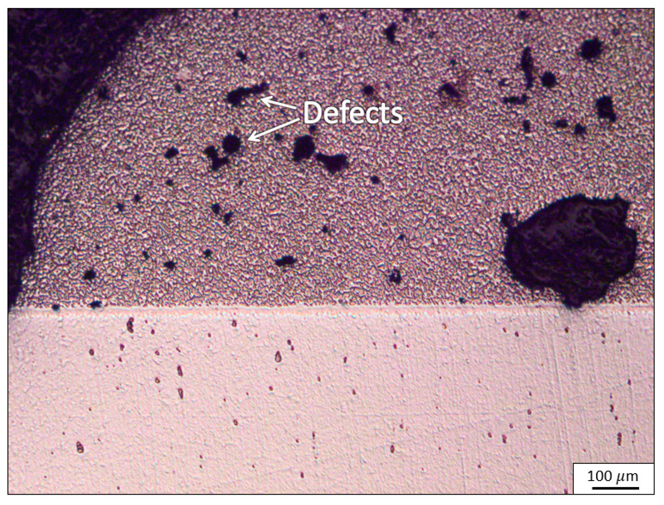
For the induction brazing process at temperature 950 °C, the microstructure obtained after brazing duration of 10 min was found to contain numerous defects, as shown in Figure 2. The temperature of 950 °C was found to be too low for the induction brazing, so further investigations focused on higher temperatures.
The microstructure images of specimens S2 to S7 are shown in Figure 3. The figure shows that the holding temperature of 1050 °C and 1150 °C produce good brazing layers that do not contain any observable defects. A significant number of Ni-enriched solid solution matrix (Ni-matrix) was observed to have grown upward from the brazing interface of the specimens. This could be attributed to the directional cooling of the specimen down to the unheated platform where the specimen was placed. These Ni-matrixes form in the brazed layer when the melting point depressants such as silicon, boron and phosphorus in that region of the layer have fully dissolved or have diffused to the base material.
There is a distinct difference in Ni-matrix growth from the six investigated parameter combinations. The percentage of Ni-matrix in the brazed layer was observed to increase largely with increasing brazing temperature and increasing brazing duration. The effect of brazing temperature was found to be relatively more significant as compared to the effect of brazing time.
The microhardness results of the specimens are also shown in Figure 3. Microhardness was obtained as it is one of the key properties in evaluating brazing repair. The results show that the grown Ni-matrix in the brazed layer reduces the overall hardness of the brazed layer. As shown in the figure, for specimen S3, the microhardness of the grown Ni-matrix was tested to be at around 253 HV, whereas the non-Ni-matrix region was at about 664 HV. The Ni-matrix in the brazed layer reduced its overall microhardness. Therefore, for specimen S2, as there was not much of Ni-matrix in the brazed layer, the overall microhardness was found to be the highest. Similarly, for the substrate’s microhardness, specimen S2 was also found to have the highest microhardness as compared to specimens S3 to S7. More detailed microhardness measurements at different depth locations of the specimens’ substrates are shown in Figure 4.
Microhardness was also measured in the Inconel 718 substrate at 200 μm, 400 μm and 600 μm below the brazing interface. The original as-received substrate’s microhardness was 326 HV. As shown from the figure, after induction brazing, the substrate’s microhardness of all specimens has reduced. This is related to the grain size growth of the substrate after the induction brazing process. Comparing the different depths, no significant difference in microhardness for the depth of 200 μm, 400 μm and 600 μm was observed. Comparing the different process parameters, the brazing duration of 2 min specimens (S2 and S5) showed a higher microhardness as compared to the longer brazing durations of 10 min and 20 min (S3, S4, S6 and S7). A further evaluation on the substrate’s microstructure was then carried out.
Figure 5 shows the microstructure images of the specimens’ substrate after etching. The base material’s grain boundaries can be observed. From the observation, a significant difference in the microstructure’s grain size was observed. The average grain size of the as-received material was measured using linear intercept method to be about 9.9 μm. However, after induction brazing at 1050 °C for 2 min (specimen S2), the average grain size increased to 45.5 μm (see Figure 5a). As the brazing duration increases (10 min for specimen S3 and 20 min for specimen S4), the average grain sizes were found to have increased even further, up to about 84.3 μm. Similarly, the substrate’s average grain size was found to increase as the brazing temperature increases (see Figure 5d–f). The specimens brazed at 1150 °C were found to have grain sizes larger than that of the specimens brazed at 1050 °C. This increase of substrate’s grain size reduces its microhardness.
From the optical microstructure and microhardness analysis of all the specimens, it is concluded that the brazing temperature of 950 °C is not sufficient for the induction brazing of Inconel 718 with the brazing paste AMS 4777. To obtain good brazing result with no obvious defects in the brazed layer, the brazing temperature of 1050 °C and 1150 °C are recommended. Moreover, it is to be noted that as the brazing temperature or time increases, the microhardness of the brazed layer and the substrate would decrease. This is mainly due to the more percentage of Ni-matrix grown in the brazed layer. To obtain the highest microhardness property of a brazing result, temperature and time that is high enough to ensure good brazing layer and bonding yet low enough to prevent the decrease in hardness are recommended. In this experiment, specimen S2 (1050 °C for 2 min) was found to be the optimum parameter.
A further microstructure evaluation at the interface of the specimen S2 was carried out using electron backscattered diffraction mapping and backscattered electron microscopy as shown in Figure 6. Figure 6a presents the EBSD inverse pole figure map of the specimen. Result shows that good microstructure Ni-matrix growth was obtained at the interface of this specimen with no porosity or cracking. The formed Ni-matrix in the brazed layer was observed to be a columnar dendritic grain that grew from the interface with a strong <001> orientation with respect to the growth direction (depicted in red). The pole figures for the subset image over the brazed layer show a strong {001} texture with the maximum multiple of uniform density (MUD) of 17.27, as shown in Figure 7. This preferred growth direction is common and expected in Ni-based superalloy of face-centered cubic (FCC) crystalline structure and in good agreement with the work conducted on directional solidification of Inconel 718 [19,20].
Figure 6b shows the backscattered electron micrograph of the same interface of specimen S2. In the brazed layer, three different phases can be observed (white, black and grey). Chemical compositions of these three phases (points 1, 2 and 3), together with the specimen’s substrate (point 4), were measured using energy-dispersive x-ray spectroscopy (EDS), as shown in Figure 6b. Points 1, 2 and 3 are likely to be Ni-matrix, Ni-rich boride and Cr-rich boride, respectively, based on the EDS results and result of a previous study [13]. However, currently, these phases are not confirmed, as EDS cannot detect light elements such as boron. Future works are recommended to identify these phases by X-ray diffraction analysis (XRD).
4. Conclusions
Induction brazing of Inconel 718 was carried out using AMS 4777 brazing paste at temperatures of 950 °C, 1050 °C and 1150 °C for 2 min, 10 min and 20 min. The brazing temperature of 950 °C was found to be insufficient for the induction brazing whereas the brazing temperature of 1050 °C and 1150 °C provided a good brazing layer. As the brazing temperature and time increases, the percentage of Ni-matrix in the brazed layer and the base material’s grain size increase. For repair application, the induction brazing at a lower temperature and shorter time would be preferred. In our experiment, the optimum parameter for induction brazing of Inconel 718 using AMS 4777 brazing paste was found to be at 1050 °C for 2 min. The research serves well to demonstrate the potential of using induction brazing for rapid localized repair, and it is hoped that the preliminary study will stimulate further research to address structural integrity issues related to the rapid localized brazing repair of aerospace components.
Author Contributions
Conceptualization, W.Z. and S.C.T.; methodology, W.Z. and S.C.T.; validation, A.A.; formal analysis and investigation, A.A., J.L.T., Y.Y. and W.Z.; data curation, A.A.; writing—original draft preparation, A.A.; writing—review and editing, W.Z., J.L.T., Y.Y. and S.C.T.; visualization, A.A.; supervision, W.Z.; project administration, W.Z. and S.C.T.; funding acquisition, W.Z. and S.C.T. All authors have read and agreed to the published version of the manuscript.
Funding
This research funding was provided by National Research Foundation of Singapore (NRF) through the Industry Alignment Fund (IAF) and by Rolls-Royce for project ARMS 1.2 Repair and Restoration of Airfoils by Induction Brazing.
Institutional Review Board Statement
Not Applicable.
Informed Consent Statement
Not Applicable.
Data Availability Statement
Not Applicable.
Acknowledgments
The authors would like to thank the School of Mechanical and Aerospace Engineering, Nanyang Technological University and Rolls-Royce@NTU Corporate Lab for the research support.
Conflicts of Interest
The authors declare no conflict of interest.
References
- Zhu, D.; Zhang, X.; Ding, H. Tool wear characteristics in machining of nickel-based superalloys. Int. J. Mach. Tools Manuf. 2013, 64, 60–77. [Google Scholar] [CrossRef]
- Çelik, A.; Alağaç, M.S.; Turan, S.; Kara, A.; Kara, F. Wear behavior of solid SiAlON milling tools during high speed milling of Inconel 718. Wear 2017, 378–379, 58–67. [Google Scholar] [CrossRef]
- Yin, Q.; Liu, Z.; Wang, B.; Song, Q.; Cai, Y. Recent progress of machinability and surface integrity for mechanical machining Inconel 718: A review. Int. J. Adv. Manuf. Technol. 2020, 109, 215–245. [Google Scholar] [CrossRef]
- Shakerin, S.; Omidvar, H.; Mirsalehi, S.E. The effect of substrate’s heat treatment on microstructural and mechanical evolution of transient liquid phase bonded IN-738 LC. Mater. Des. 2016, 89, 611–619. [Google Scholar] [CrossRef]
- Henderson, M.B.; Arrell, D.; Larsson, M.; Marchant, G. Nickel based superalloy welding practices for industrial gas turbine applications. J. Sci. Technol. Weld. Join. 2004, 9, 13–21. [Google Scholar] [CrossRef]
- Egbewande, A.T.; Buckson, R.A.; Ojo, O.A. Analysis of laser beam weldability of Inconel 738 superalloy. J. Mater. Charact. 2010, 61, 569–574. [Google Scholar] [CrossRef]
- Vitek, J.M. The effect of welding conditions on stray grain formation in single crystal welds—Theoretical analysis. J. Acta Mater. 2005, 53, 53–67. [Google Scholar] [CrossRef]
- Malekan, A.; Farvizi, M.; Mirsalehi, S.E.; Saito, N.; Nakashima, K. Influence of bonding time on the transient liquid phase bonding behavior of Hastelloy X using Ni-Cr-B-Si-Fe filler alloy. Mater. Sci. Eng. A 2019, 755, 37–49. [Google Scholar] [CrossRef]
- Sadeghian, A.; Mirsalehi, S.E.; Arhami, F.; Malekan, A.; Saito, N.; Nakashima, K. Effect of bonding time on dissimilar transient liquid phase (TLP) bonding of IN939 to IN625 superalloys: Microstructural characterization and mechanical properties. Metall. Mater. Trans. A 2021, 52, 1526–1539. [Google Scholar] [CrossRef]
- Arhami, F.; Mirsalehi, S.E. Micostructual evolution and mechanical properties evaluation of IN-939 bonds made by isothermal solidification of a liquated Ni-Cr-B interlayer. Metall. Mater. Trans. A 2018, 49, 6197–6214. [Google Scholar] [CrossRef]
- Kazazi, A.; Ekrami, A. Corrosion behavior of TLP bonded stainless steel 304 with Ni-based interlayer. J. Manuf. Process. 2019, 42, 131–138. [Google Scholar] [CrossRef]
- AlHazaa, A.; Haneklaus, N. Diffusion bonding and transient liquid phase (TLP) bonding of type 304 and 316 austenitic stainless steel—A review of similar and dissimilar material joints. Metals 2020, 10, 613. [Google Scholar] [CrossRef]
- Jalivand, V.; Omidvar, H.; Shakeri, H.R.; Rahimipour, M.R. Microstructure evolution during transient liquid phase bonding of Inconel 738LC using AMS 4777 filler alloy. Mater. Charact. 2013, 75, 20–28. [Google Scholar] [CrossRef]
- Zhang, Y.C.; Yu, X.T.; Jiang, W.; Tu, S.T.; Zhang, X.C. Elastic modulus and hardness characterization for microregion of Inconel 625/BNi-2 vacuum brazed joint by high temperature nanoindentation. Vacuum 2020, 181, 109582. [Google Scholar] [CrossRef]
- Wu, X.; Chandel, R.S.; Pheow, S.H.; Li, H. Brazing of Inconel X-750 to stainless steel 304 using induction process. Mater. Sci. Eng. A 2000, 288, 84–90. [Google Scholar] [CrossRef]
- Blue, C.A.; Lin, A.; Ray, Y. Rapid infrared joining of titanium alloys and titanium matrix composites. In Materials Research Society Symposium Proceedings; Materials Research Society: Pittsburgh, PA, USA, 1993; Volume 314, pp. 143–148. [Google Scholar]
- Wu, X.; Chandel, R.S.; Li, H.; Seow, H.P.; Wu, S. Induction brazing of Inconel 718 to Inconel X-750 using Ni-Cr-Si-B amorphous foil. J. Mater. Process. Technol. 2000, 104, 34–43. [Google Scholar] [CrossRef]
- Jiang, C.; Chen, H.; Wang, Q.; Li, Y. Effect of brazing temperature and holding time on joint properties of induction brazed WC-Co/carbon steel using Ag-based alloy. J. Mater. Process. Technol. 2016, 229, 562–569. [Google Scholar] [CrossRef]
- Bean, G.E.; McLouth, T.D.; Witkin, D.B.; Sitzman, S.D.; Adams, P.M.; Zaldivar, R.J. Build orientation effects on texture and mechanical properties of selective laser melting Inconel 718. J. Mater. Eng. Perform. 2019, 28, 1942–1949. [Google Scholar] [CrossRef]
- Hinojos, A.; Mireles, J.; Reichardt, A.; Frigola, P.; Hosemann, P.; Murr, L.E.; Wicker, R.B. Joining of Inconel 718 and 316 stainless steel using electron beam melting additive manufacturing technology. Mater. Des. 2016, 94, 17–27. [Google Scholar] [CrossRef] [Green Version]
Figure 1.
Experimental setup: (a) AMS 4777 brazing paste applied on the top surface of Inconel 718 base metal; (b) the stand-off distance was set at 10 mm; (c) pyrometer and thermocouple setup for temperature control and monitoring.
Figure 1.
Experimental setup: (a) AMS 4777 brazing paste applied on the top surface of Inconel 718 base metal; (b) the stand-off distance was set at 10 mm; (c) pyrometer and thermocouple setup for temperature control and monitoring.

Figure 2.
Optical micrograph showing microstructure of specimen S1 (950 °C for 10 min) with numerous defects.
Figure 2.
Optical micrograph showing microstructure of specimen S1 (950 °C for 10 min) with numerous defects.

Figure 3.
Microstructure and microhardness analysis of induction brazing results of different process parameters: (a) 1050 °C for 2 min; (b) 1050 °C for 10 min; (c) 1050 °C for 20 min; (d) 1150 °C for 2 min; (e) 1150 °C for 10 min; (f) 1150 °C for 20 min.
Figure 3.
Microstructure and microhardness analysis of induction brazing results of different process parameters: (a) 1050 °C for 2 min; (b) 1050 °C for 10 min; (c) 1050 °C for 20 min; (d) 1150 °C for 2 min; (e) 1150 °C for 10 min; (f) 1150 °C for 20 min.

Figure 4.
Microhardness at different depth locations of the specimens’ substrates.

Figure 5.
Etched substrate revealing the grain boundaries of the specimens: (a) 1050 °C for 2 min; (b) 1050 °C for 10 min; (c) 1050 °C for 20 min; (d) 1150 °C for 2 min; (e) 1150 °C or 10 min; (f) 1150 °C for 20 min.
Figure 5.
Etched substrate revealing the grain boundaries of the specimens: (a) 1050 °C for 2 min; (b) 1050 °C for 10 min; (c) 1050 °C for 20 min; (d) 1150 °C for 2 min; (e) 1150 °C or 10 min; (f) 1150 °C for 20 min.

Figure 6.
Interface of specimen S2 (1050 °C for 2 min): (a) EBSD inverse pole figure (IPF-Y) map; (b) Backscatter electron micrograph showing different phases in the brazed layer (points 1, 2 and 3) and in the substrate (point 4) and their chemical composition (wt.%) measured by EDS.
Figure 6.
Interface of specimen S2 (1050 °C for 2 min): (a) EBSD inverse pole figure (IPF-Y) map; (b) Backscatter electron micrograph showing different phases in the brazed layer (points 1, 2 and 3) and in the substrate (point 4) and their chemical composition (wt.%) measured by EDS.

Figure 7.
Pole figures of the brazed layer region of specimen S2 (1050 °C for 2 min).


Table 1.
Chemical composition (wt.%) of the materials used.
| Materials | Chemical Composition (wt.%) | ||||||||
|---|---|---|---|---|---|---|---|---|---|
| Ni | Cr | Fe | Nb | Mo | Ti | B | Si | Al | |
| Inconel 718 | 53.41 | 18.59 | 17.98 | 5.07 | 2.89 | 0.98 | 0.0023 | 0.08 | 0.56 |
| AMS 4777 | 82.0 | 7.0 | 3.0 | - | - | - | 3.1 | 4.5 | - |
Table 2.
Seven parameter combinations investigated in this study.
| Specimen No. | Process Parameters Set | Actual Temperature from Thermocouple Reading |
|---|---|---|
| S1 | 950 °C for 10 min | 945 °C |
| S2 | 1050 °C for 2 min | 1025 °C |
| S3 | 1050 °C for 10 min | 1040 °C |
| S4 | 1050 °C for 20 min | 1060 °C |
| S5 | 1150 °C for 2 min | 1120 °C |
| S6 | 1150 °C for 10 min | 1080 °C |
| S7 | 1150 °C for 20 min | 1125 °C |
Publisher’s Note: MDPI stays neutral with regard to jurisdictional claims in published maps and institutional affiliations. |
© 2021 by the authors. Licensee MDPI, Basel, Switzerland. This article is an open access article distributed under the terms and conditions of the Creative Commons Attribution (CC BY) license (https://creativecommons.org/licenses/by/4.0/).
Share and Cite
MDPI and ACS Style
Aprilia, A.; Tan, J.L.; Yang, Y.; Tan, S.C.; Zhou, W. Induction Brazing for Rapid Localized Repair of Inconel 718. Metals 2021, 11, 1096. https://doi.org/10.3390/met11071096
AMA Style
Aprilia A, Tan JL, Yang Y, Tan SC, Zhou W. Induction Brazing for Rapid Localized Repair of Inconel 718. Metals. 2021; 11(7):1096. https://doi.org/10.3390/met11071096
Chicago/Turabian StyleAprilia, Aprilia, Jin Lee Tan, Yongjing Yang, Sung Chyn Tan, and Wei Zhou. 2021. "Induction Brazing for Rapid Localized Repair of Inconel 718" Metals 11, no. 7: 1096. https://doi.org/10.3390/met11071096
Note that from the first issue of 2016, this journal uses article numbers instead of page numbers. See further details here.