Fe–Si–Al Coatings with Stable Wear Resistance Prepared by Laser Cladding Industrial Wastes
by
 ,
,
Xue Liu
1,* ,
,
Bin-Bin Ma
1,2,
Li-Wei Hu
1,
Jin-Feng Li
1,
Feng-Sheng Qu
1,
Guo-Min Le
1,* and
Xiu-Yan Li
2,* 1
Institute of Materials, China Academy of Engineering Physics, Mianyang 621907, China
2
College of Physics and Optoelectronics, Taiyuan University of Technology, Taiyuan 030024, China
*
Authors to whom correspondence should be addressed.
Metals 2019, 9(1), 96; https://doi.org/10.3390/met9010096
Submission received: 17 December 2018
/
Revised: 10 January 2019
/
Accepted: 14 January 2019
/
Published: 17 January 2019
(This article belongs to the Special Issue Additive Layer Manufacturing using Metal Deposition)
Abstract
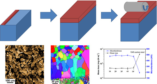
:Because wear is one of the most common reasons for the failure of metals, the development of a low-cost coating with enhanced wear resistance is of great importance. In the present study, Fe–Si–Al coatings with superior and stable wear resistance were prepared by laser cladding Fe–Si–Al industrial waste onto 1045 carbon steel. The microstructure, as well as the wear mechanism of the Fe–Si–Al coatings, was investigated. The Fe–Si–Al coatings consist of a (Al, Fe, Si) solid solution phase in both columnar grain form and equiaxed grain form. The Fe–Si–Al coatings possess enhanced microhardness of 494 ± 15 HV0.3 and low mass loss of 5 × 10⁻⁵ mg·(N·m)−1. The wear resistance is ten times higher than that of the 1045 carbon steel matrix. The wear of the Fe–Si–Al coatings is mainly dominated by abrasive wear and adhesive wear. This work provides important insight into the preparation of low-cost, wear-resistant coatings, as well as stable, superior wear resistance.
1. Introduction
Wear is one of the most common reasons for the failure of metallic materials [1,2]. Thus, the improvement of wear resistance, thereby extending the serving life of metallic materials, is of great importance [3]. The laser cladding technique provides an effective method to significantly improve the wear-resisting capability of the metal by cladding a thin wear-resistant coating on its surface [4,5]. The thin, cladded coating can effectively reduce the cost of anti-wear materials [6,7]. Moreover, the cladded coating has a very limited influence on the matrix by creating a so-called heat-affected zone (HAZ) [8,9]. Different from other coating preparation techniques, such as physical vapor deposition or chemical vapor deposition, laser-cladded coating exhibits reliable metallurgical bonding between the coating and the matrix [10]. Therefore, the laser cladding technique has attracted increasing attention.
However, the powder that is used in laser cladding is usually very expensive, and the wear resistance of the cladded coatings is quite sensitive to the cladding parameters [11,12]. These factors have prevented wide industrialization of the laser cladding technique in the anti-wear field. Thus, it is meaningful to develop a laser-cladded coating that is low cost and has stable, superior wear resistance.
Fe–Si–Al metallic glass (MG) possesses excellent soft magnetic properties [13] and has wide applications in the field of transformers. The industrialized production of Fe–Si–Al MG ribbons has been realized, creating readily accessible leftover material and flotsam. By crushing the leftover material and flotsam from Fe73.7Si13.8Al12.5 ribbon production, Fe–Si–Al powder can be obtained at a very low cost. Moreover, Fe–Si–Al is a typical single-phase solid solution alloy, and the simple precipitated phase can make Fe–Si–Al coatings exhibit very stable properties. Additionally, the powder prepared from a Fe–Si–Al ribbon possesses very good composition uniformity compared with a mixed powder of pure Fe, Si, and Al, and the uniformity of the powder greatly benefits the structural uniformity of the cladded coating.
It is well-known that 1045 carbon steel is widely used in the production of gears. Thus, the enhancement of the wear resistance of 1045 carbon steel can extend the service life of such products. In the present work, Fe–Si–Al coatings were prepared on 1045 carbon steel to enhance their wear resistance by laser cladding with Fe–Si–Al industrial waste. The microstructure, as well as the wear-resistance properties of the Fe–Si–Al coatings, was investigated. The prepared Fe–Si–Al coatings exhibit stable microhardness of 470–500 HV0.3 and low mass loss of ~4 mg against the ring-block wear test under different cladding parameters. This work provides important insights into the preparation of wear-resistant coatings at a low cost, as well as into stable, superior wear resistance.
2. Materials and Methods
The Fe73.7Si13.8Al12.5 powder was prepared by crushing the leftover material and flotsam from the production of Fe73.7Si13.8Al12.5 ribbons, which was provided by the Advanced Technology & Materials Co., Ltd. (Beijing, China). The two sources from the initial Fe–Si–Al ribbons are distinct. The leftover material is fully amorphous, while the flotsam is partly amorphous or even fully crystallized. The Fe–Si–Al ribbons were subjected to a crystallization process to make the structure uniform before crushing. The Fe–Si–Al powder was fully crystallized, as shown in Figure S1 in the Supplementary Materials. To investigate the diameter distribution and the morphology of the powder, the Fe73.7Si13.8Al12.5 powder was subjected to Mira 3LMH scanning electron microscope (SEM) (Tescan, Brno, Czech Republic) inspection and a S3500 laser particle size analyzer (Microtrac, Montgomeryville, PA, USA). Before the laser cladding process, the Fe–Si–Al powder was heated up to 353 K for 2 h and then cooled down to room temperature under a vacuum to remove any moisture. Then, the powder was used to clad the coatings in an argon atmosphere with oxygen and moisture contents below 20 ppm.
Annealed 1045 carbon steel plates with dimensions of ~100 mm × 50 mm × 10 mm were used as the substrates. An ytterbium-doped fiber laser unit with a wavelength of 1070 nm and a spot diameter of ~1.8 mm was used as the power source. By applying a closed-loop powder feed unit, the powder was delivered into a laser molten pool at a speed of ~7 g·min−1 to deposit Fe–Si–Al onto the polished carbon steel substrates. The Fe–Si–Al coatings were formed by the overlap of single clad passes with an optimized overlap ratio of 45%. The width of the single clad passes of Fe–Si–Al coating specimen 1–specimen 5 were about 2.09 mm, 2.23 mm, 2.81 mm, 2.90 mm, and 2.87 mm, respectively. By selecting different laser power and scanning speeds, Fe–Si–Al coating specimen 1–specimen 5 were prepared, and the corresponding preparing parameters are listed in Table 1.
After grinding to reduce the surface roughness, the structures of the laser-cladded coatings were examined by Dandong Tongda TD-3500 X-ray diffraction (XRD) (Tongda, Dandong, China) with Cu Kα radiation at a scanning rate of 4 degrees per min and a detecting step of 0.02 degree. The cross sections of the laser-cladded specimens were grinded, polished, and etched by a 4% nitric acid alcohol solution for 10 s and then subjected to BMM-33 optical microscope (Shanghai Guangyi, Shanghai, China) and Tescan Mira 3LMH SEM inspection to investigate their microstructures. Additionally, parts of the specimens were vibration polished and then inspected by an electron backscatter diffraction (EBSD) (Oxford Instruments, Oxford, England) system in a Tescan Mira 3LMH SEM. The microhardness of the coating was measured by a HVS-1000A digital microhardness tester (Huayin, Laizhou, China) with a load of 3 N and a holding time of 15 s.
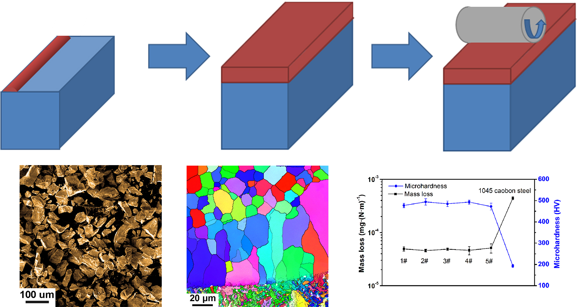
As one of the most used wear test techniques, the ring-block wear test [14,15] was employed to evaluate the wear resistance of the laser-cladded coating. The as-prepared specimen was cut into specimens with dimensions of 12 mm × 16 mm × 8 mm without surface grinding. The wear surface possessed dimensions of 12 mm × 16 mm, as shown in the illustration presented in Figure 1. The wear test was conducted under the dry condition without temperature controlling at room temperature. A M2000 block-on-ring wear test machine (Kesheng, Shandong, China) was employed to conduct the ring-block wear test with a sliding velocity of 0.471 m·s−1 for 30 min. According to the previous literature [16], the applied load was selected to be 100 N. The anti-friction rings were fabricated by GCr15 with a hardness of 750 HV0.3, a diameter of 45 mm, and a thickness of 12 mm.
3. Results and Discussion
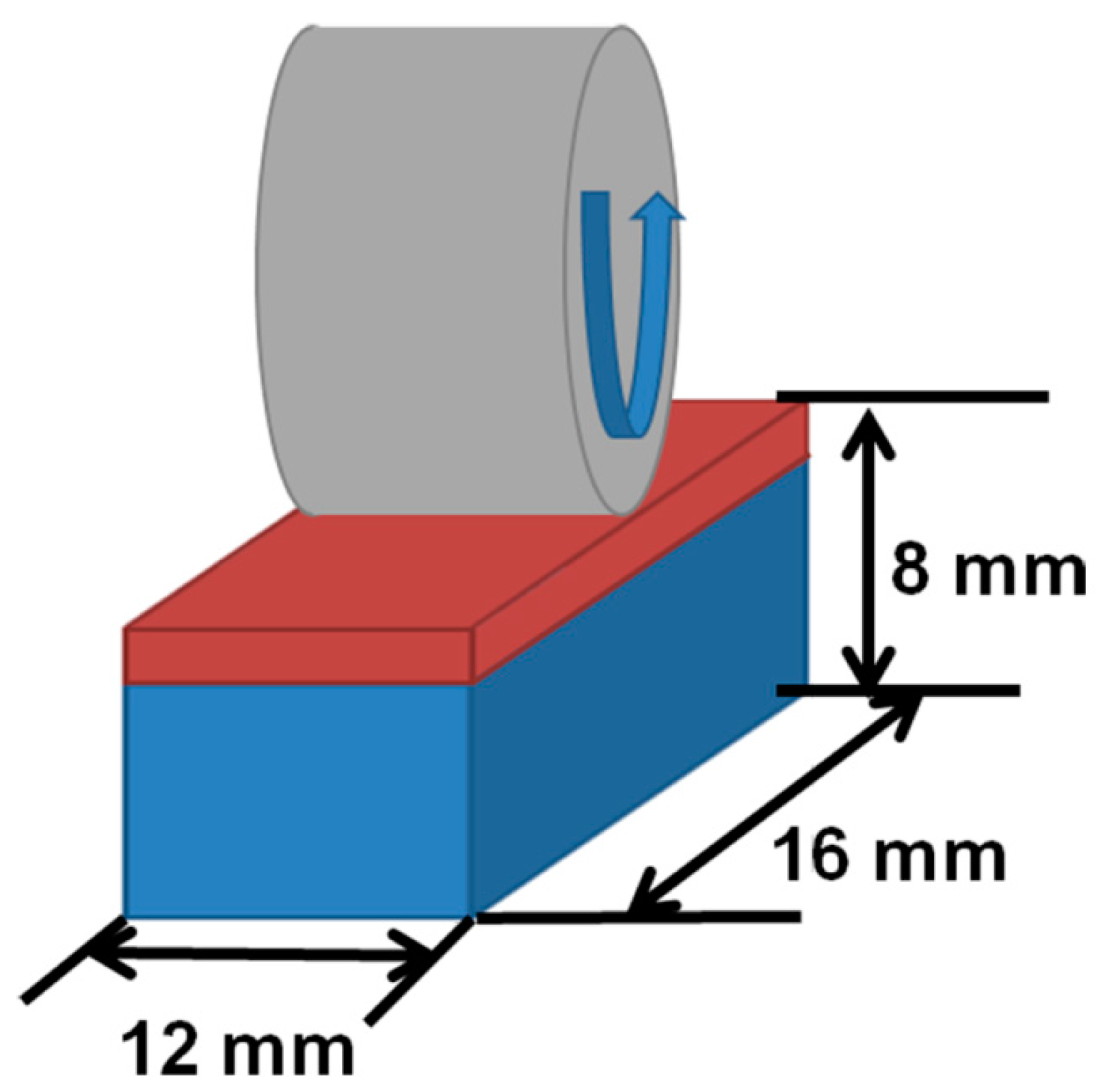
Because the quality of the powder has a significant influence on the property of the laser-cladded samples, the morphology and the diameter distribution of the Fe–Si–Al powder were inspected. Figure 2a shows the SEM image of the Fe–Si–Al powder. Because the Fe–Si–Al powder is prepared by crushing the leftover material and flotsam of the ribbons, the powder exhibits irregular shapes with sharp corners. Figure 2b shows the diameter distribution of the Fe–Si–Al powder. It can be seen that the diameter of the powder varies from 20 μm to 300 μm. The median particle diameter D50 (the diameter with cumulative frequency of 50%) is 97 μm.
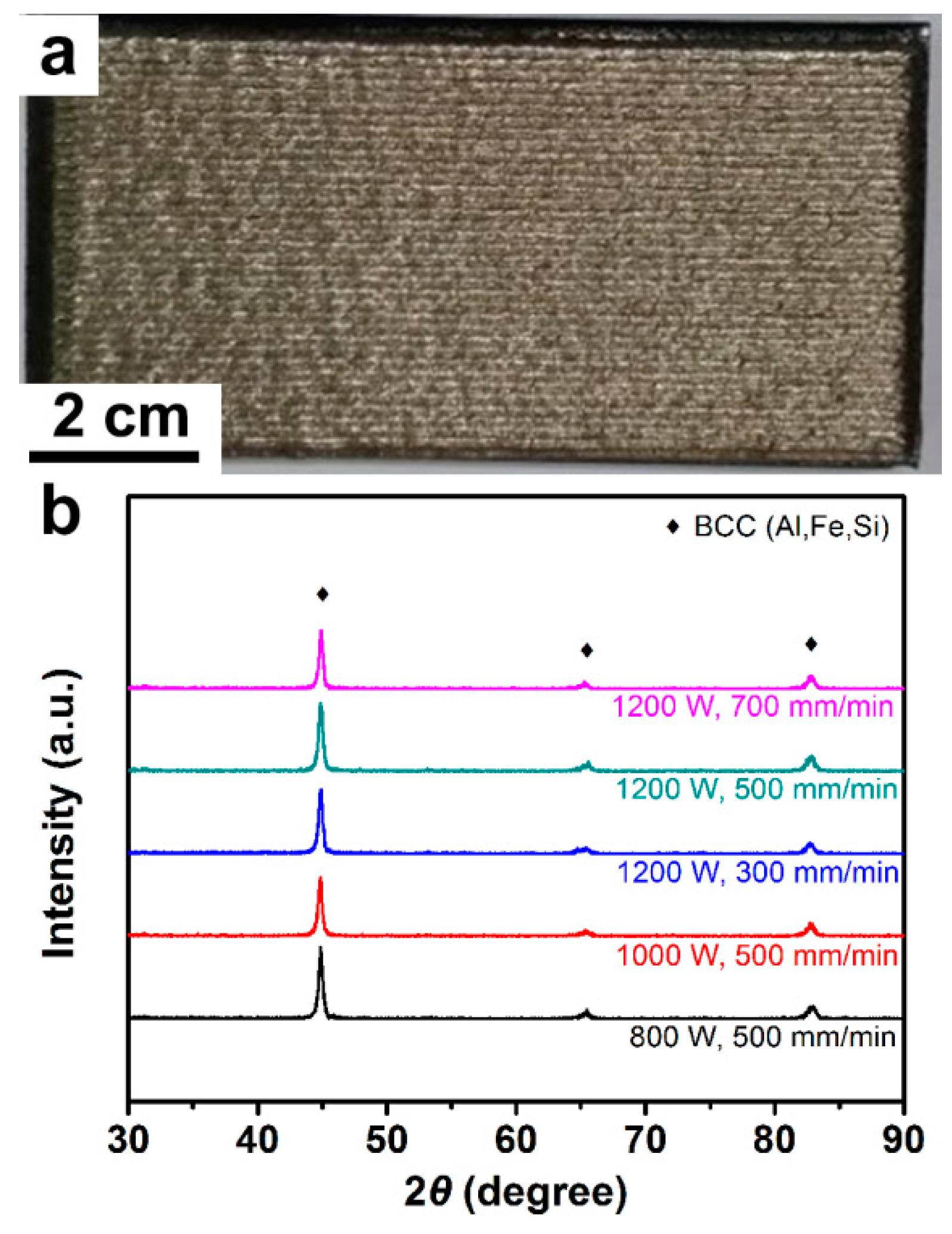
Figure 3a exhibits a typical photograph of the as-prepared Fe–Si–Al coating specimen. The coating specimen possesses a relatively flat surface without obvious cracks on a ~100 mm × 50 mm area, indicating good processing quality. Some periodical ripples can be noticed on the surface of the prepared specimens. It is well known that powder with a sphere shape is the best raw material for laser cladding. The Fe–Si–Al powder exhibits high powder-using efficiency of the Fe–Si–Al at about 80%. The high powder-using efficiency, as well as the quality of the cladded surface, indicates that the Fe–Si–Al powder is quite suitable for laser cladding.
The XRD spectra of the Fe–Si–Al coating specimens are shown in Figure 3b. The five XRD spectra present very similar shapes. There are three obvious peaks sitting at ~44.9°, 65.5°, and 82.8° and several small peaks can also be observed. After calibration, all the peaks were confirmed to correspond to the (Al, Fe, Si) solid solution phase with a body-centered cubic (BCC) structure. Thus, the XRD results indicate that the five laser-cladded coatings all consist of the (Al, Fe, Si) solid solution phase. The structure of the Fe–Si–Al coating is quite stable under different cladding parameters.
Figure S2 in the Supplementary Materials shows typical SEM images of the cross-sectional profile of the cladded layer of coating specimen 5. It can be seen that the coating is metallurgically bonded to the substrate. The coating is quite dense, and almost no pores were observed. However, the grains are hard to distinguish in the SEM images. Then, the coating specimens were inspected by optical microscope.
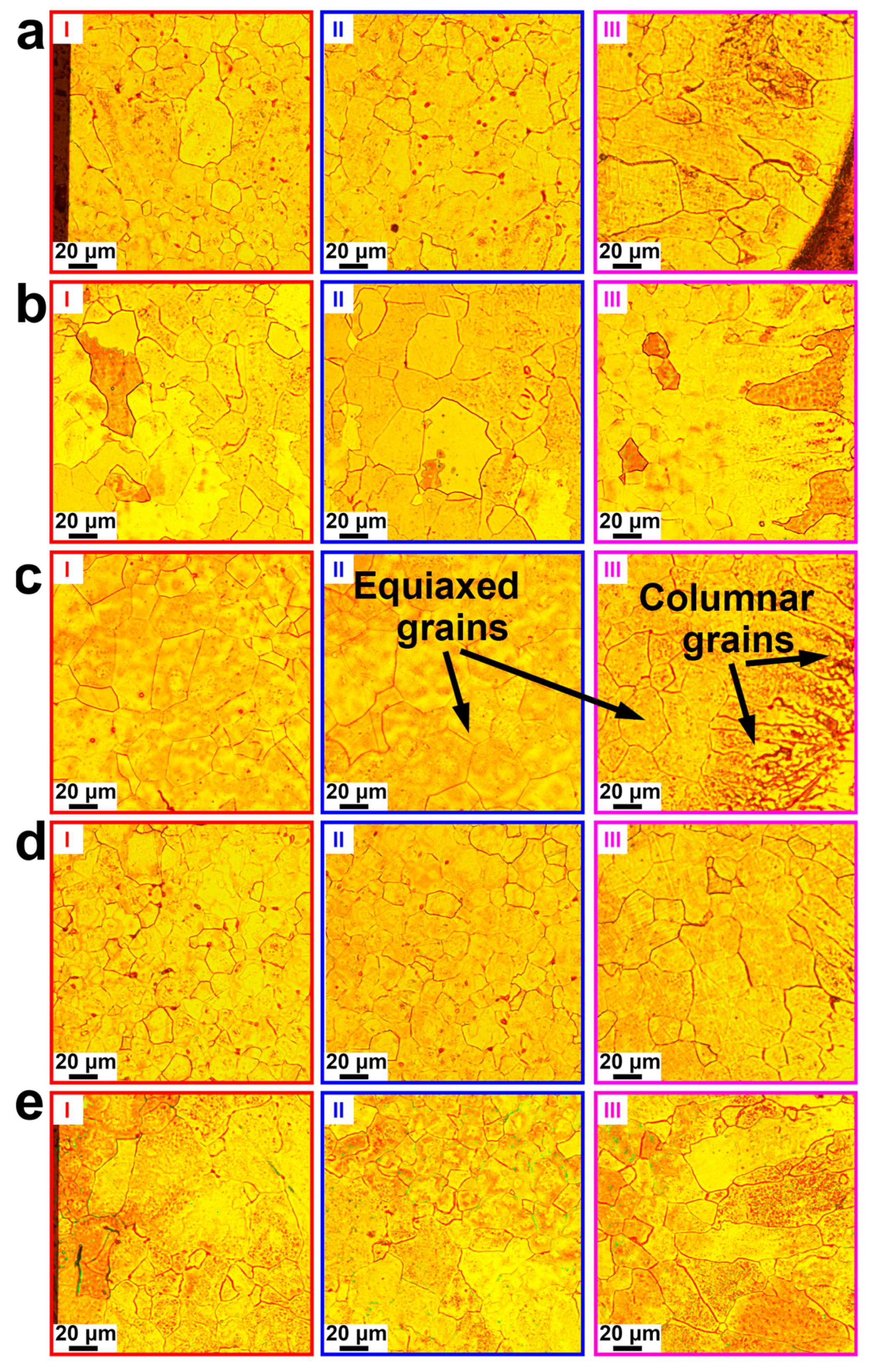
Figure S3 in the Supplementary Materials shows optical microscope images of the whole cladded layer of the Fe–Si–Al coating specimens. The thicknesses of coating specimen 1–specimen 5 were measured to be about 1.39 mm, 1.57 mm, 2.37 mm, 1.73 mm, and 1.27 mm, respectively. No obvious cracks and very few pores could be found on any of the specimens, indicating the high cladding quality of the prepared Fe–Si–Al coatings. Figure 4 shows the enlarged optical microscope images. Areas I, II, and III show the top, middle, and bottom of the cladded layer, respectively. These cladding layers consist of columnar grains and equiaxed grains. The columnar grains are located adjacent to the carbon steel substrate and then translated into equiaxed grains up to the top of the cladded layer.
The solidification morphology of metal is usually determined by the temperature gradient (G) and solidification velocity (R) [8,17]. The growth of columnar grains tends to form under higher G/R values while that of equiaxed grains tends to form under lower G/R values [17]. In the laser cladding process, the unmelted carbon steel substrate acts as a heat sink, creating a heat flux gradient. Adjacent to the carbon steel substrate, the columnar grains grow opposite to the heat flux and form an epitaxial growth feature. G is highest at the bottom of the cladded layer and rapidly decreases with the increasing distance from the bottom, slowly decreasing up to the surface of the cladded layer. In contrast, R reaches the lowest value at the bottom of the cladded layer and then rapidly increases with the increasing distance from the bottom, slowly increasing up to the surface of the cladded layer [8]. Therefore, in the cladded layer, the G/R value keeps decreasing, resulting in the columnar-to-equiaxed transition.
It can be also seen that the grain size of the equiaxed grains firstly increases and then decreases along the deposition direction in all of the Fe–Si–Al coating specimens. The grain size is mainly dominated by the cooling rate, which can be evaluated by G/R [17]. Generally, a high G/R value will cause a fine grain structure [8]. As mentioned above, G keeps increasing and R keeps decreasing with the increasing distance from the bottom. This makes G/R reach a maximum value in the middle of the cladded layer, which results the grain size in the middle of the cladded layer being smaller than in other parts. According to the optical microscope images shown in Figure 4, by employing the intercept method, the average grain sizes of cladded specimen 1–specimen 5 were measured to be 26 ± 10 μm, 20 ± 4 μm, 23 ± 3 μm, 21 ± 5 μm, and 29 ± 8 μm, respectively. It can be seen that the average grain size is not so sensitive to the preparation parameters, which indicates that the laser-cladded Fe–Si–Al coatings are quite suitable for industrial production.
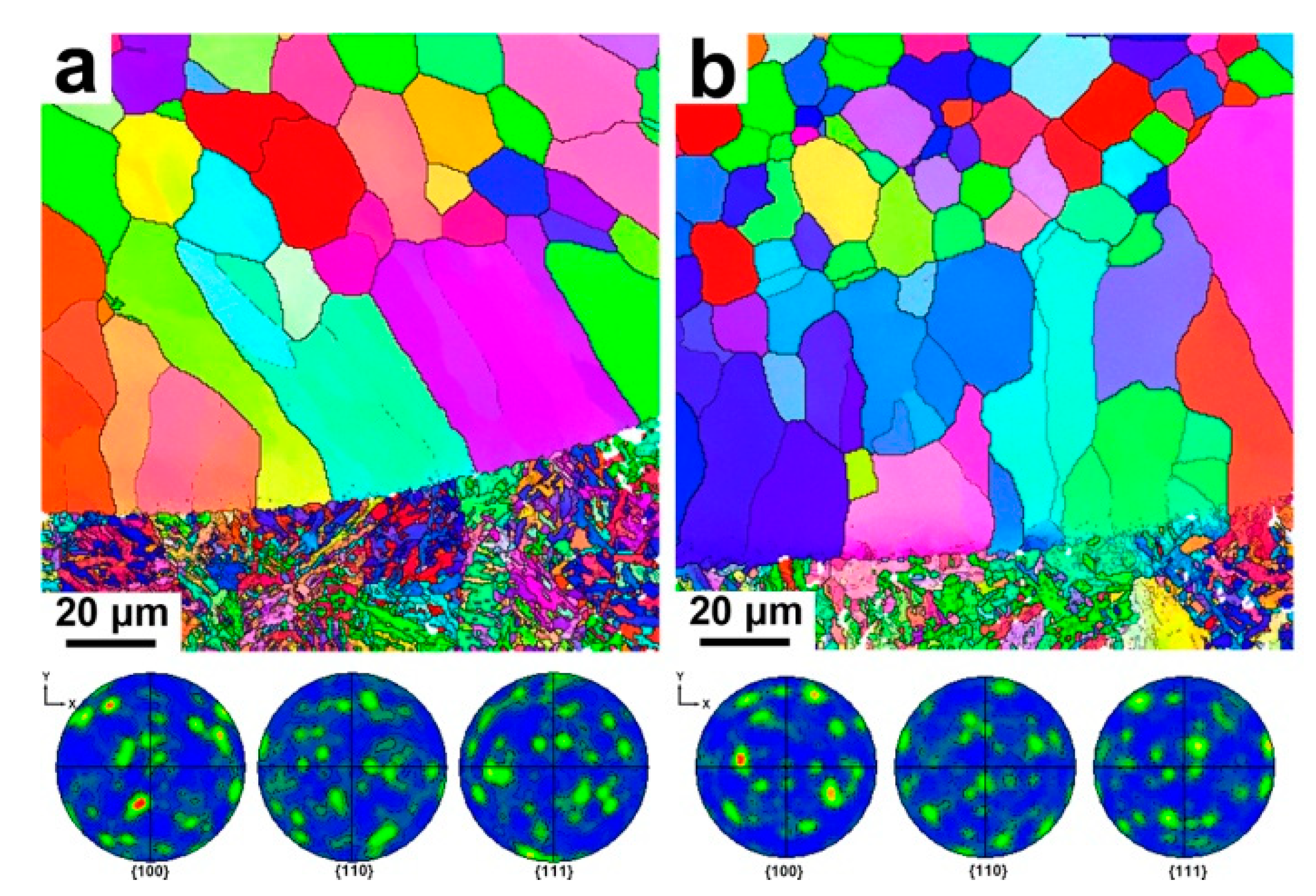
Fibrous texture is usually observed on the laser-cladded coatings. In order to determine the preferred crystallographic orientation of the coating specimen, the specimens were subjected to EBSD inspection. Figure 5a shows the inverse pole figure-X direction (IPF-X) EBSD maps of the bottom region of the Fe–Si–Al coating specimen 1. The cladded layer and the heat-affected zone HAZ [18] were separated by a continuous fusion line. After calibration, the grains in the cladded layer were confirmed to consist of a Fe-based solid solution phase with a BCC structure, which is consistent with the XRD results. No cracks were found around the fusion line, indicating that the cladded coating possesses good metallurgical bonding with the carbon steel substrate. Fine grains with mean size of ~3 μm were observed in the 1045 carbon steel substrate. Before the cladding process, the annealed 1045 carbon steel substrate is constituted by ferrite and pearlite [18,19]. During the laser cladding processing, the HAZ is heated above the Ac3 line, and the nucleation of austenite starts within the ferrite [19]. Because the temperature of the HAZ subsequently quickly drops, there is not enough time for the growth of the austenite, leaving fine austenite grains in the HAZ. Then, the austenite transforms into ferrite again during the rapid cooling process [20], and fine grains form in the HAZ.
Above the fusion line, a layer of columnar grains followed by equiaxed grains were observed. There were some small angle grain boundaries in the columnar grains (see the dashed line in Figure 4a). According to the previous literature [8,21], these columnar grains may grow epitaxially from parent grains in the HAZ along the heat flux direction. Then, due to the weaker thermal gradient, the epitaxial growth stops, and equiaxed grains form. The corresponding {100}, {110}, and {111} pole figures of specimen 1 are also presented in Figure 4a. The signal dispersed in the pole figures, indicating a random texture in the Fe–Si–Al cladding. Similar morphology was observed in the other Fe–Si–Al coating specimens, as shown in Figure 4b.
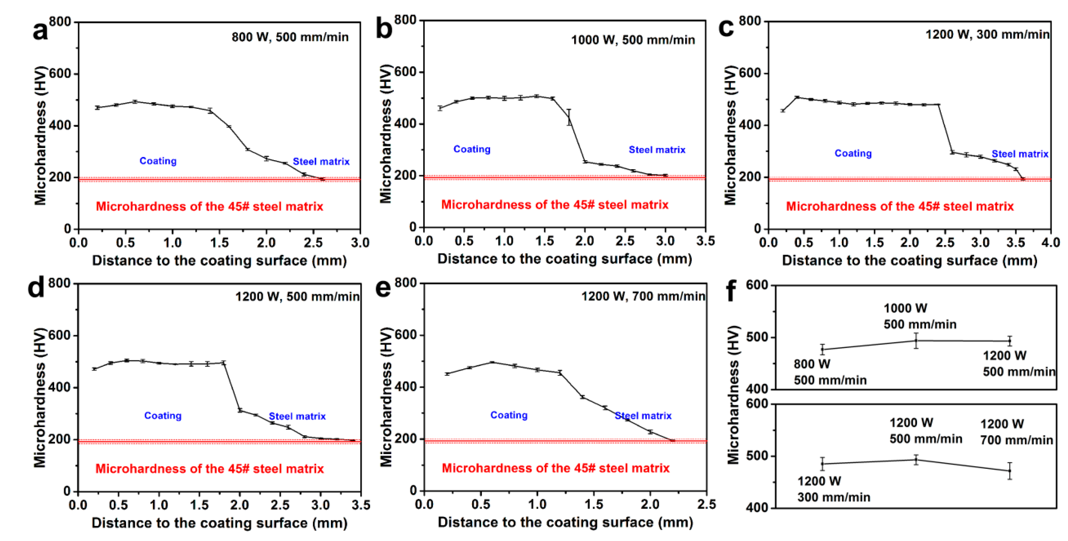
The microhardness distribution of Fe–Si–Al-cladded specimen 1–specimen 5 is presented in Figure 6a–e, respectively. It can be seen that the five curves exhibit very similar tendencies. In the cladded layer, the microhardness keeps a high value approaching 500 HV0.3. Some microhardness fluctuation was noticed in this area, which was caused by the changing of the grain sizes, as presented in Figure 4. At the edge of the cladded layer, the microhardness rapidly dropped to about 300 HV0.3 due to the significant difference between the cladded layer and the steel matrix. Then, the microhardness slowly dropped to a value equal to that of the steel matrix in the HAZ. Because the steel matrix was subjected to an annealing process before the laser cladding process, the rapid heating and cooling effect of the laser cladding can refine the grain and increase the microhardness of the HAZ. However, the grain refinement effect will decrease with the increasing distance from the cladded layer, resulting a slow drop of the microhardness in the HAZ.
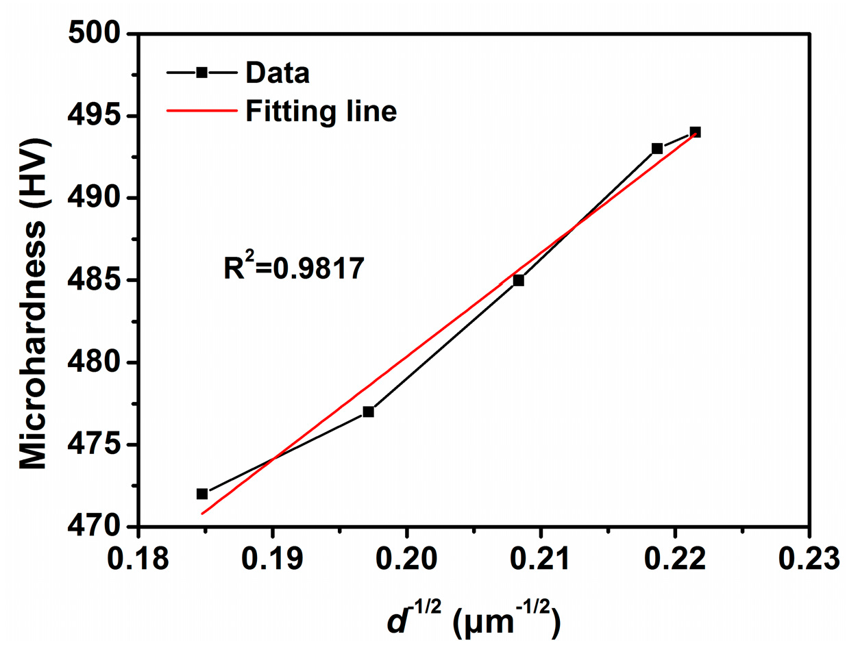
As shown in Figure 6f, the average microhardness in the cladded layers of coating specimen specimen 1–specimen 5 was calculated to be 477 ± 10 HV0.3, 494 ± 15 HV0.3, 485 ± 13 HV0.3, 493 ± 9 HV0.3, and 471 ± 16 HV0.3, respectively. The microhardness of the carbon steel substrate was also measured to be only 193 ± 7 HV0.3. Thus, the Fe–Si–Al cladded layer can significantly improve the microhardness of the 1045 carbon steel substrate. No obvious relationship can be found between the microhardness and the applied laser power/scanning speed. However, by comparing the average grain sizes and the average microhardness of the prepared coating specimens, it can be found that there seems to be some relationship between them, i.e., the larger grain size corresponds to the lower microhardness. Because the Fe–Si–Al coatings have a single-phase solid solution structure, the relationship between the grain size and the strength/hardness should be ruled by the Hall-Petch equation.
The Hall-Petch equation quantitatively describes the strength increasing with the decreasing grain size in single-phase alloys [22]. According to the Hall-Petch equation, the relationship between the yield strength σs and the grain size d of metals can be described as follows:
where σ0 and k0 are constants for a certain metal.
σs = σ0 + k0·d−1/2
Moreover, hardness is usually positively correlated with the yield strength in metals, and there is an empirical formula for microhardness MH and yield strength σs [23]:
where k1 is a constant for a certain metal.
MH = k1·σs
Then, the following can be found:
where σ2 and k2 are constants for a certain metal.
MH = σ2 + k2·d−1/2
Figure 7 shows the average microhardness plotted as a function of the average grain sizes of the prepared coating specimens. It can be found that the microhardness of the prepared coating specimens increases with the increasing d−1/2 value. After linear fitting, which is widely used in the literature [24], the microhardness was confirmed to depend linearly on the d−1/2 values with an R square value of higher than 0.99. Therefore, the relationship between the microhardness and the grain size in the prepared Fe–Si–Al coatings matches Equation (3), i.e., the hardness of the Fe–Si–Al coatings is ruled by the Hall-Petch equation. Therefore, the microhardness of the Fe–Si–Al coatings is mainly dominated by the grain sizes, and the microhardness of the coatings can be tuned by controlling the grain sizes.
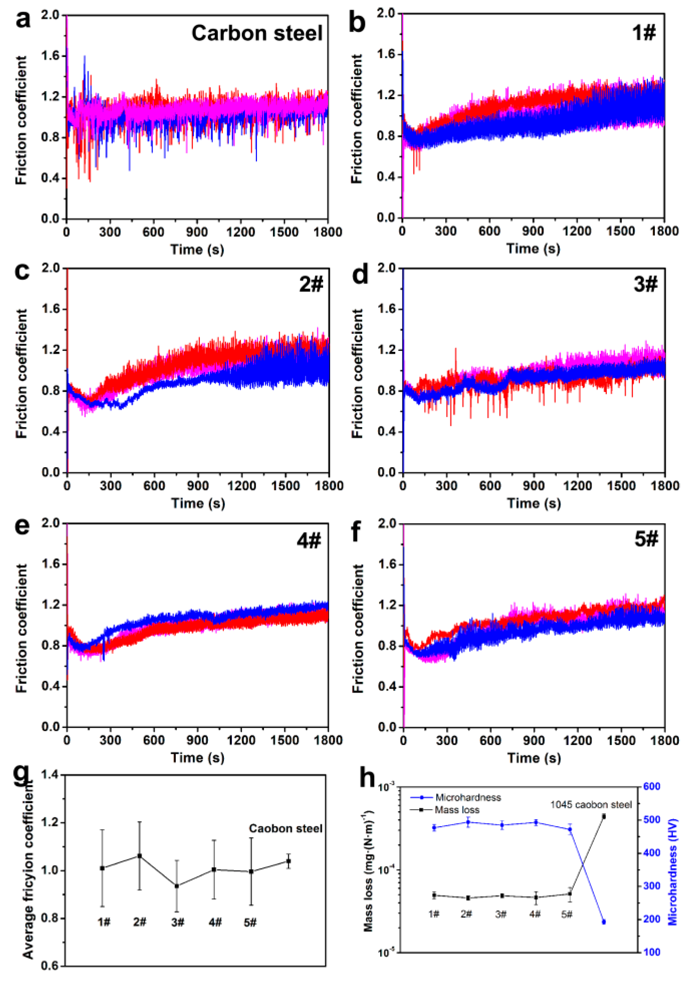
Figure 8a shows the friction coefficient variation curves of the 1045 carbon steel. The friction coefficient is relatively stable after a short period of adjustment and presents a tendency to slowly increase. Different from the 1045 carbon steel, some fluctuations were observed in the friction coefficient variation curves of coating specimen 1–specimen 5, as shown in Figure 8b,f. Moreover, the friction coefficient increasing rate of the coating specimens is higher than that of the 1045 carbon steel. The average friction coefficient of coating specimen 1–specimen 5 and the 1045 carbon steel is presented in Figure 8g. It can be seen that the average friction coefficient of the coating specimens is slightly lower than that of the 1045 carbon steel, and obvious fluctuations were noticed in the average friction coefficient of the coating specimens. Due to the fact that the surfaces of the coating specimens are not flat, new contact points would generate during the wear test. The observed fluctuations and the friction coefficient increasing might be caused by the disturbance of the newly generated contact points.
To quantitatively evaluate the wear resistance of the coating specimens, the mass loss during the block-on-ring wear test was measured, and the results are presented in Figure 8h. It can be found that mass losses of coating specimen 1–specimen 5 are (4.9 ± 0.5) × 10−5 mg·(N·m)−1, (4.6 ± 0.3) × 10−5 mg·(N·m)−1, (4.9 ± 0.3) × 10−5 mg·(N·m)−1, (4.6 ± 0.8) × 10−5 mg·(N·m)−1, and (5.1 ± 9.9) × 10−5 mg·(N·m)−1, respectively, while that of the 1045 carbon steel is as high as (44.3 ± 2.9) × 10−5 mg·(N·m)−1. Therefore, the prepared Fe–Si–Al coatings can effectively improve the wear resistance of the 1045 carbon steel up to an order of magnitude. It has been reported that the steel coating produced by friction surfacing can improve the wear resistance of the 1045 steel matrix by 35% [25]. The Fe–Mo alloy coating fabricated by plasma transferred arc cladding possesses enhanced wear resistance of about 5 times that of the 1045 steel matrix [26]. The Ni–Cr–B–Si alloy coatings prepared by continual local induction cladding can effectively increase the wear resistance of the 1045 steel by 6–10 times [27]. It can be seen that the prepared Fe–Si–Al coatings have achieved a much better strengthening effect. Although there are some other coatings that have an even better improvement effect than the Fe–Si–Al coatings, such as the laser-cladded Ni–Cr–B–Si coatings [28], the ultrahigh content of expensive metals such as Ni and Cr severely limits it application. Therefore, as compared to the previous work, the prepared Fe–Si–Al possesses excellent wear resistance, as well as quite a low cost.
Because the prepared Fe–Si–Al coatings are solid solutions with a single phase, the wear resistance of the coating specimens may be mainly dominated by the grain size. By comparing the mass loss and the microhardness of coating specimen 1–specimen 5 (seeing Figure 8h), it can be found that the mass loss decreases with the increasing microhardness. It has been found that microhardness has a negative relationship with grain size. Thus, the wear resistance of the Fe–Si–Al coating specimens is mainly dominated by grain size.
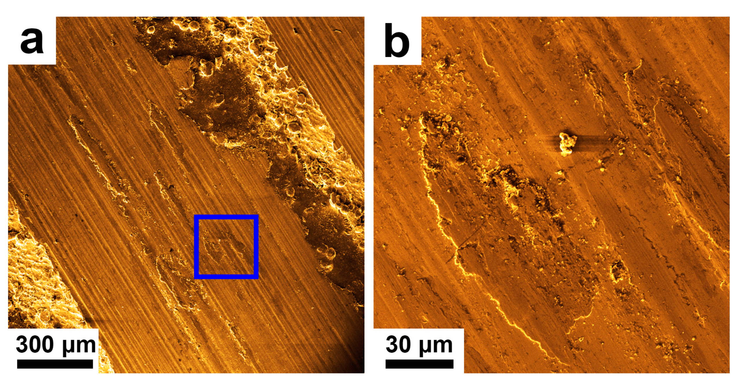
To find out the wear mechanism of the coating specimens, the wear scars were observed by SEM. Figure 9a shows the wear scar of coating specimen 4. Obvious scratches along the relative sliding direction can be observed. Some areas showed different morphologies in the scratches, as marked in Figure 9a. Figure 9b shows the enlarged SEM image of this area, where surface spall was observed. The scratches and surface spall are reported as the feature morphology corresponding to abrasive wear and adhesive wear, respectively [3,29]. Thus, abrasive wear and adhesive wear are the primary wear mechanisms. Figure S4 in the Supplementary Materials shows the optical microscope images of the wear scars of coating specimen 1–specimen 5 and the 1045 carbon steel. It can be seen that the wear scars are very similar to that of coating specimen 4. Therefore, abrasive wear and adhesive wear are the primary wear mechanism for the Fe–Si–Al coating specimens and the 1045 carbon steel.
4. Conclusions
Fe–Si–Al coatings, consisting of a (Al, Fe, Si) solid solution phase in both columnar grain form and equiaxed grain form, were prepared by the laser cladding of Fe–Si–Al industrial waste. The prepared Fe–Si–Al coatings exhibited enhanced microhardness of 470–500 HV0.3 and stable low mass loss of ~5 × 10⁻⁵ mg·(N·m)−1 in the block-on-ring wear test under different cladding parameters. The wear resistance of the Fe–Si–Al coating is about one order of magnitude better than the 1045 steel matrix. Abrasive wear and adhesive wear were found to be the primary wear mechanism for the Fe–Si–Al coating specimens. The application of the Fe–Si–Al powder, which is prepared from the leftover material or the flotsam from the industry-produced Fe–Si–Al ribbon, can significantly decrease costs. The low, raw material costs, as well as the stable wear resistance, give the Fe–Si–Al coating great potential for application as a wear-resistant coating.
Supplementary Materials
The following are available online at https://www.mdpi.com/2075-4701/9/1/96/s1. Figure S1: The XRD spectrum of the Fe–Si–Al powder. Figure S2: The SEM images of the cross-sectional profile of the cladded layer of coating specimen 5. (a) The bottom area of the coating. (b) The middle area of the of the coating. (c) The top area of the coating. Figure S3: The optical microscope images of the cross-sectional profiles of the cladded layers of coating (a) specimen 1, (b) specimen 2, (c) specimen 3, (d) specimen 4 and (e) specimen 5. Figure S4: The optical microscope images of the wear scar of (a) the Fe-Si-Al coating specimen 1, (b) the Fe-Si-Al coating specimen 2, (c) the Fe-Si-Al coating specimen 3, (d) the Fe-Si-Al coating specimen 4, and (e) the Fe-Si-Al coating specimen 5, and (f) the 1045 carbon steel.
Author Contributions
Conceptualization, X.L.; validation, B.-B.M., L.-W.H., and X.L.; investigation, B.-B.M., X.L., and L.-W.H.; resources, X.L. and G.-M.L.; data curation, X.L.; original draft preparation, X.L.; review and editing, J.-F.L., F.-S.Q., G.-M.L., and X.-Y.L.; visualization, B.-B.M and X.L.; supervision, X.L.; and funding acquisition, X.L. and G.-M.L.
Funding
This research was funded by the National Natural Science Foundation of China, grant numbers 51601176 and 51401189.
Conflicts of Interest
The authors declare no conflict of interest.
References
- Fu, Z.K.; Ding, H.H.; Wang, W.J.; Liu, Q.Y.; Guo, J.; Zhu, M.H. Investigation on microstructure and wear characteristic of laser cladding Fe-based alloy on wheel/rail materials. Wear 2015, 330, 592–599. [Google Scholar] [CrossRef]
- Guo, Y.X.; Shang, X.J.; Liu, Q.B. Microstructure and properties of in-situ tin reinforced laser cladding CoCr2FeNiTix high-entropy alloy composite coatings. Surf. Coat. Technol. 2018, 344, 353–358. [Google Scholar] [CrossRef]
- Mao, J.; Feng, A.; Cheng, B.; Li, Z.; Wu, H.; Huang, Y.; Zhang, H. Microstructure and friction and wear properties of Fe-based alloy coatings by laser cladding. Hot Work. Technol. 2017, 46, 139–142. [Google Scholar]
- Hua, H.; Ting, Z.; Ma, M.; Liu, W. Microstructure and wear resistance of laser cladding particulate reinforced Fe-based composite coating on railway steel. J. Laser Appl. 2017, 29, 022503. [Google Scholar]
- Kumar, S.; Mandal, A.; Das, A.K.; Dixit, A.R. Parametric study and characterization of AlN–Ni–Ti6Al4V composite cladding on titanium alloy. Surf. Coat. Technol. 2018, 349, 37–49. [Google Scholar] [CrossRef]
- Wang, K.M.; Chang, B.H.; Lei, Y.P.; Fu, H.G.; Lin, Y.H. Effect of cobalt on microstructure and wear resistance of Ni-based alloy voating fabricated by laser cladding. Metals 2017, 7, 12. [Google Scholar] [CrossRef]
- Yang, J.; Huang, J.H.; Fan, D.Y.; Chen, S.H. Microstructure and wear properties of Fe–6wt.%Cr–0.55wt.%C–xwt.%Nb laser cladding coating and the mechanism analysis. Mater. Des. 2015, 88, 1031–1041. [Google Scholar] [CrossRef]
- Bai, L.; Le, G.; Liu, X.; Li, J.; Xi, S.; Li, X. Grain morphologies and microstructures of laser melting deposited V-5Cr-5Ti alloys. J. Alloys Compd. 2018, 745, 716–724. [Google Scholar] [CrossRef]
- Chen, J.L.; Zhou, Y.J.; Shi, C.; Mao, D.H. Microscopic analysis and electrochemical behavior of Fe-based coating produced by laser cladding. Metals 2017, 7, 9. [Google Scholar] [CrossRef]
- Weng, Z.K.; Wang, A.H.; Wang, Y.Y.; Xiong, D.H.; Tang, H.Q. Diode laser cladding of Fe–based alloy on ductile cast iron and related interfacial behavior. Surf. Coat. Technol. 2016, 286, 64–71. [Google Scholar] [CrossRef]
- Zhang, L.; Wang, C.S.; Qian, S.N.; Yu, Q.; Dong, C. Microstructure and wear resistance of laser-clad (Co, Ni)(61.2)B26.2Si7.8Ta4.8 coatings. Metals 2017, 7, 7. [Google Scholar] [CrossRef]
- Zhang, H.; Chong, K.; Zhao, W.; Sun, Z.P. Effects of pulse parameters on in-situ Ti-V carbides size and properties of Fe-based laser cladding layers. Surf. Coat. Technol. 2018, 344, 163–169. [Google Scholar] [CrossRef]
- Li, G.; Cui, Y.; Zhang, N.; Wang, X.; Xie, J.L. The precipitation in annealing and its effect on permittivity of Fe-Si-Al powders. Physica B 2016, 481, 1–7. [Google Scholar] [CrossRef]
- Fernandes, L.; Silva, F.J.G.; Paiva, O.C.; Baptista, A.; Pinto, G. Minimizing the adhesion effects in food packages forming by the use of advanced coatings. Procedia Manuf. 2018, 17, 886–894. [Google Scholar] [CrossRef]
- Fernandes, L.; Silva, F.J.G.; Andrade, M.F.; Alexandre, R.; Baptista, A.P.M.; Rodrigues, C. Improving the punch and die wear behavior in tin coated steel stamping process. Surf. Coat. Technol. 2017, 332, 174–189. [Google Scholar] [CrossRef]
- Krajewski, W.K.; Greer, A.L.; Krajewski, P.K. Trends in the development of high-aluminium zinc alloys of stable structure and properties. Arch. Metall. Mater. 2013, 58, 845–847. [Google Scholar] [CrossRef]
- Kou, S. Welding Metallurgy; John Wiley & Sons, Inc.: Hoboken, NJ, USA, 2003. [Google Scholar]
- Li, Y.J.; Dong, S.Y.; Yan, S.X.; He, P.; Xu, B.S. Phase evolution of ductile iron during laser cladding processing. Surf. Coat. Technol. 2018, 339, 37–47. [Google Scholar] [CrossRef]
- Zhao, X.; Yang, X.L.; Jing, T.F. Effect of initial microstructure on warm deformation behavior of 45 steel. J. Iron Steel Res. Int. 2012, 19, 75–78. [Google Scholar] [CrossRef]
- Lu, S.Y.; Yao, K.F.; Chen, Y.B.; Wang, M.H.; Liu, X.; Ge, X.Y. The effect of tempering temperature on the microstructure and electrochemical properties of a 13wt.% Cr-type martensitic stainless steel. Electrochim. Acta 2015, 165, 45–55. [Google Scholar] [CrossRef]
- Wang, Y.F.; Li, G.; Wang, C.S.; Xia, Y.L.; Sandip, B.; Dong, C. Microstructure and properties of laser clad Zr-based alloy coatings on Ti substrates. Surf. Coat. Technol. 2004, 176, 284–289. [Google Scholar] [CrossRef]
- Lee, Y.S.; Ha, S.; Park, J.H.; Lee, S.B. Structure-dependent mechanical behavior of copper thin films. Mater. Charact. 2017, 128, 68–74. [Google Scholar] [CrossRef]
- Raynor, D.; Silcock, J.M. Strengthening mechanisms in γ′ precipitating alloys. Met. Sci. J. 1970, 4, 121–130. [Google Scholar] [CrossRef]
- Andrade, M.F.C.; Martinho, R.P.; Silva, F.J.G.; Alexandre, R.J.D.; Baptista, A.P.M. Influence of the abrasive particles size in the micro-abrasion wear tests of TiAlSiN thin coatings. Wear 2009, 267, 12–18. [Google Scholar] [CrossRef] [Green Version]
- Pereira, D.; Gandra, J.; Pamies-Teixeira, J.; Miranda, R.M.; Vilaca, P. Wear behaviour of steel coatings produced by friction surfacing. J. Mater. Process. Technol. 2014, 214, 2858–2868. [Google Scholar] [CrossRef]
- Deng, X.K.; Zhang, G.J.; Wang, T.; Ren, S.; Bai, Z.L.; Cao, Q. Investigations on microstructure and wear resistance of Fe-Mo alloy coating fabricated by plasma transferred arc cladding. Surf. Coat. Technol. 2018, 350, 480–487. [Google Scholar] [CrossRef]
- Chen, X.; Qin, X.; Zhu, Z.; Gao, K. Microstructural evolution and wear properties of the continual local induction cladding NiCrBSi coatings. J. Mater. Process. Technol. 2018, 262, 257–268. [Google Scholar] [CrossRef]
- Wang, Z. Microstructure and wear resistance of laser-cladding NiCrSiB coating. Spec. Cast. Nonferr. Alloys 2013, 33, 509–511. [Google Scholar]
- Liu, X.; Liu, H.; Wang, D.; Wang, E.P.; Liu, W.J.; Yao, K.F.; Chen, N. Metallic glass-strengthened thermoplastic elastomer composites. Physica E 2017, 90, 37–41. [Google Scholar] [CrossRef]
Figure 1.
Illustration of the wear tests.

Figure 2.
(a) SEM image and (b) diameter distribution of the Fe–Si–Al powder.

Figure 3.
(a) Photograph of the Fe–Si–Al coating specimen 1 and (b) XRD spectra of the Fe–Si–Al-coat specimens.
Figure 3.
(a) Photograph of the Fe–Si–Al coating specimen 1 and (b) XRD spectra of the Fe–Si–Al-coat specimens.

Figure 4.
Optical microscope images of the cross-sectional profiles of the cladded layers of (a) specimen 1, (b) specimen 2, (c) specimen 3, (d) specimen 4, and (e) specimen 5.
Figure 4.
Optical microscope images of the cross-sectional profiles of the cladded layers of (a) specimen 1, (b) specimen 2, (c) specimen 3, (d) specimen 4, and (e) specimen 5.

Figure 5.
Inverse pole figure-X direction (IPF-X) electron backscatter diffraction (EBSD) maps of the bottom regions of Fe–Si–Al coating (a) specimen 1 and (b) specimen 4 with their corresponding {100}, {110}, and {111} pole figures.
Figure 5.
Inverse pole figure-X direction (IPF-X) electron backscatter diffraction (EBSD) maps of the bottom regions of Fe–Si–Al coating (a) specimen 1 and (b) specimen 4 with their corresponding {100}, {110}, and {111} pole figures.

Figure 6.
The hardness distribution of the Fe–Si–Al coating (a) specimen 1, (b) specimen 2, (c) specimen 3, (d) specimen 4, (e) and specimen 5 and (f) the average microhardness of the coatings.
Figure 6.
The hardness distribution of the Fe–Si–Al coating (a) specimen 1, (b) specimen 2, (c) specimen 3, (d) specimen 4, (e) and specimen 5 and (f) the average microhardness of the coatings.

Figure 7.
The average microhardness plotted as a function of the average grain sizes of the prepared coating specimens.
Figure 7.
The average microhardness plotted as a function of the average grain sizes of the prepared coating specimens.

Figure 8.
The friction coefficient variation curves of (a) the 1045 carbon steel and (b–f) coating specimen 1–specimen 5, (g) the average friction coefficient, and (h) the mass loss and microhardness comparison of the coating specimens and the 1045 carbon steel.
Figure 8.
The friction coefficient variation curves of (a) the 1045 carbon steel and (b–f) coating specimen 1–specimen 5, (g) the average friction coefficient, and (h) the mass loss and microhardness comparison of the coating specimens and the 1045 carbon steel.

Figure 9.
The SEM images of the wear scar of Fe–Si–Al coating specimen 4. (a) the wear scar of coating specimen 4; (b) the enlarged SEM image of (a).
Figure 9.
The SEM images of the wear scar of Fe–Si–Al coating specimen 4. (a) the wear scar of coating specimen 4; (b) the enlarged SEM image of (a).


Table 1.
Parameters of the laser-cladded Fe–Si–Al coatings.
| Sample No. | Laser Powder (W) | Scan Speed (mm/min) | Heat Import (kJ) |
|---|---|---|---|
| Specimen 1 | 800 | 500 | 403 |
| Specimen 2 | 1000 | 500 | 468 |
| Specimen 3 | 1200 | 300 | 744 |
| Specimen 4 | 1200 | 500 | 432 |
| Specimen 5 | 1200 | 700 | 319 |
© 2019 by the authors. Licensee MDPI, Basel, Switzerland. This article is an open access article distributed under the terms and conditions of the Creative Commons Attribution (CC BY) license (http://creativecommons.org/licenses/by/4.0/).
Share and Cite
MDPI and ACS Style
Liu, X.; Ma, B.-B.; Hu, L.-W.; Li, J.-F.; Qu, F.-S.; Le, G.-M.; Li, X.-Y. Fe–Si–Al Coatings with Stable Wear Resistance Prepared by Laser Cladding Industrial Wastes. Metals 2019, 9, 96. https://doi.org/10.3390/met9010096
AMA Style
Liu X, Ma B-B, Hu L-W, Li J-F, Qu F-S, Le G-M, Li X-Y. Fe–Si–Al Coatings with Stable Wear Resistance Prepared by Laser Cladding Industrial Wastes. Metals. 2019; 9(1):96. https://doi.org/10.3390/met9010096
Chicago/Turabian StyleLiu, Xue, Bin-Bin Ma, Li-Wei Hu, Jin-Feng Li, Feng-Sheng Qu, Guo-Min Le, and Xiu-Yan Li. 2019. "Fe–Si–Al Coatings with Stable Wear Resistance Prepared by Laser Cladding Industrial Wastes" Metals 9, no. 1: 96. https://doi.org/10.3390/met9010096
Note that from the first issue of 2016, this journal uses article numbers instead of page numbers. See further details here.