Article

Microstructure and Mechanical Properties of Medium Carbon Steel Deposits Obtained via Wire and Arc Additive Manufacturing Using Metal-Cored Wire

1
Department of Materials Science and Engineering, Delft University of Technology, Mekelweg 2, 2628CD Delft, The Netherlands
2
Rotterdam Fieldlab Additive Manufacturing BV, Scheepsbouwweg 8, 3089JW Rotterdam, The Netherlands
3
Department of Mechanics of Solids, Faculty of Engineering Technology, Surfaces & Systems (MS3), Chair of Laser Processing, University of Twente, P.O. Box 217, 7500 AE Scheduled, The Netherlands
*
Author to whom correspondence should be addressed.
Metals 2019, 9(6), 673; https://doi.org/10.3390/met9060673
Submission received: 30 April 2019 / Revised: 3 June 2019 / Accepted: 8 June 2019 / Published: 10 June 2019
(This article belongs to the Special Issue Arc-based Additive Manufacturing)

Abstract

:
Wire and arc additive manufacturing (WAAM) is a 3D metal printing technique based on the arc welding process. WAAM is considered to be suitable to produce large-scale metallic components by combining high deposition rate and low cost. WAAM uses conventional welding consumable wires as feedstock. In some applications of steel components, one-off spare parts need to be made on demand from steel grades that do not exist as commercial welding wire. In this research, a specifically produced medium carbon steel (Grade XC-45), metal-cored wire, equivalent to a composition of XC-45 forged material, was deposited with WAAM to produce a thin wall. The specific composition was chosen because it is of particular interest for the on-demand production of heavily loaded aerospace components. The microstructure, hardness, and tensile strength of the deposited part were studied. Fractography studies were conducted on the tested specimens. Due to the multiple thermal cycles during the building process, local variations in microstructural features were evident. Nevertheless, the hardness of the part was relatively uniform from the top to the bottom of the construct. The mean yield/ultimate tensile strength was 620 MPa/817 MPa in the horizontal (deposition) direction and 580 MPa/615 MPa in the vertical (build) direction, respectively. The elongation in both directions showed a significant difference, i.e., 6.4% in the horizontal direction and 11% in the vertical direction. Finally, from the dimple-like structures observed in the fractography study, a ductile fracture mode was determined. Furthermore, a comparison of mechanical properties between WAAM and traditionally processed XC-45, such as casting, forging, and cold rolling was conducted. The results show a more uniform hardness distribution and higher tensile strength of the WAAM deposit using the designed metal-cored wires.

1. Introduction

Additive manufacturing (AM) processes produce 3D components directly from dedicated 3D CAD models by depositing material layer-by-layer. AM offers the advantage of building parts with geometric and composition complexities, which are difficult to produce by conventional subtractive manufacturing processes [1,2]. Wire and arc additive manufacturing (WAAM) is an AM technique that combines an electric arc as a heat source and a consumable wire as feedstock. It can be considered as a modification of the classical gas metal arc welding (GMAW) process. Due to its high deposition rate, high material utilization, and short production lead time compared to powder-based direct energy deposition (DED) techniques, WAAM has been considered for applications in the aerospace [3,4], automotive [1,5], and marine [6,7] sectors. In addition, several kinds of traditional arc welding techniques, such as gas metal arc welding (GMAW), gas tungsten arc welding (GTAW), and plasma arc welding (PAW), have also been applied on WAAM, all of which have different deposition features, and thus application fields. Other than these, some variants of GMAW, such as cold metal transfer (CMT) and tandem GMAW, have also been created and used to improve the quality and efficiency of deposition in GMAW-based WAAM. However, from these existing methods, the faster deposition rate of GMAW (up to 160 g/min) makes it the ideal candidate for the production of large-scale parts in short time spans [8,9], and it has become the most popular process in WAAM [10]. An example related to large-scale parts in the marine sector is the WAAMpeller, the world’s first class approved 3D printed ship propeller [11].
To the best knowledge of the authors, not all existing welding consumables have been assessed for the applicability of WAAM, and only a limited amount of institutions focus on developing alloys dedicated to WAAM. The market demand for special alloys is still not commercially attractive [12] due to the small volumes required for WAAM at the moment. The production process of solid wires involving casting and drawing of specific chemistry is only economically viable when large volumes are involved. The current growth in WAAM applications will boost WAAM consumable material development in the near future. WAAM applications typically refer to small batch production or prototypes, which often require special wire compositions or which can benefit from tailoring the consumable composition for the desired components. Metal-cored wires are particularly suitable to produce one-off or small-batch consumable compositions. A metal-cored wire consists of a metal sheath and a core filled with various powders. Compared to flux-cored wires [13], the number of fluxing agents is reduced in metal-cored wires, which is beneficial for controlling the formation of inclusions in the weld metal. The alloy composition of metal-cored wires can be further optimized to reduce the sensitivity towards certain weld defects, such as cracking and porosity. Metal-cored wires are also suitable for repairing or manufacturing a spare component with a chemical composition that does not match that of existing welding consumables. WAAM applications can benefit significantly from this flexibility introduced by metal-cored wires.
Metal-cored wires consisting of a solid sheath and a powder core (Figure 1), do not offer the rigidity that solid wires do [14]. During a deposition, metal-cored wires conduct current only through the sheath, which results in higher current density. The powder inside the sheath is melted by the arc, resulting in the formation of powder lance towards the base. However, there is no energy transfer via the powder lance, which means that less energy is required to melt the same volume of the metal-cored wire than the solid wire. Due to this case, the heat input in the WAAM component is reduced, which benefits the decrease of the penetration. Additionally, to obtain similar deposition characteristics, i.e., bead shape, aspect ratio, and deposition speed, a metal-cored wire would require relatively lower current than a solid wire, which is beneficial in the case of WAAM.
The advantages of metal-cored wires mentioned attracted the attention of many researchers and research institutions in the past two decades [15,16]. The studies indicate that metal-cored wires are a good alternative for additive manufacturing. Nevertheless, the application of only limited metal-cored wires in WAAM has been reported [17,18].
In the present study, a medium carbon steel metal-cored wire is investigated for GMAW-based WAAM. The specific composition was chosen because it is of particular interest for the production of heavily loaded aerospace components and this chemical composition does not exist as commercial welding wire. The appearance, microstructure, yield/tensile strengths, and fractography of the deposited single-bead wall were studied for potential WAAM applications.

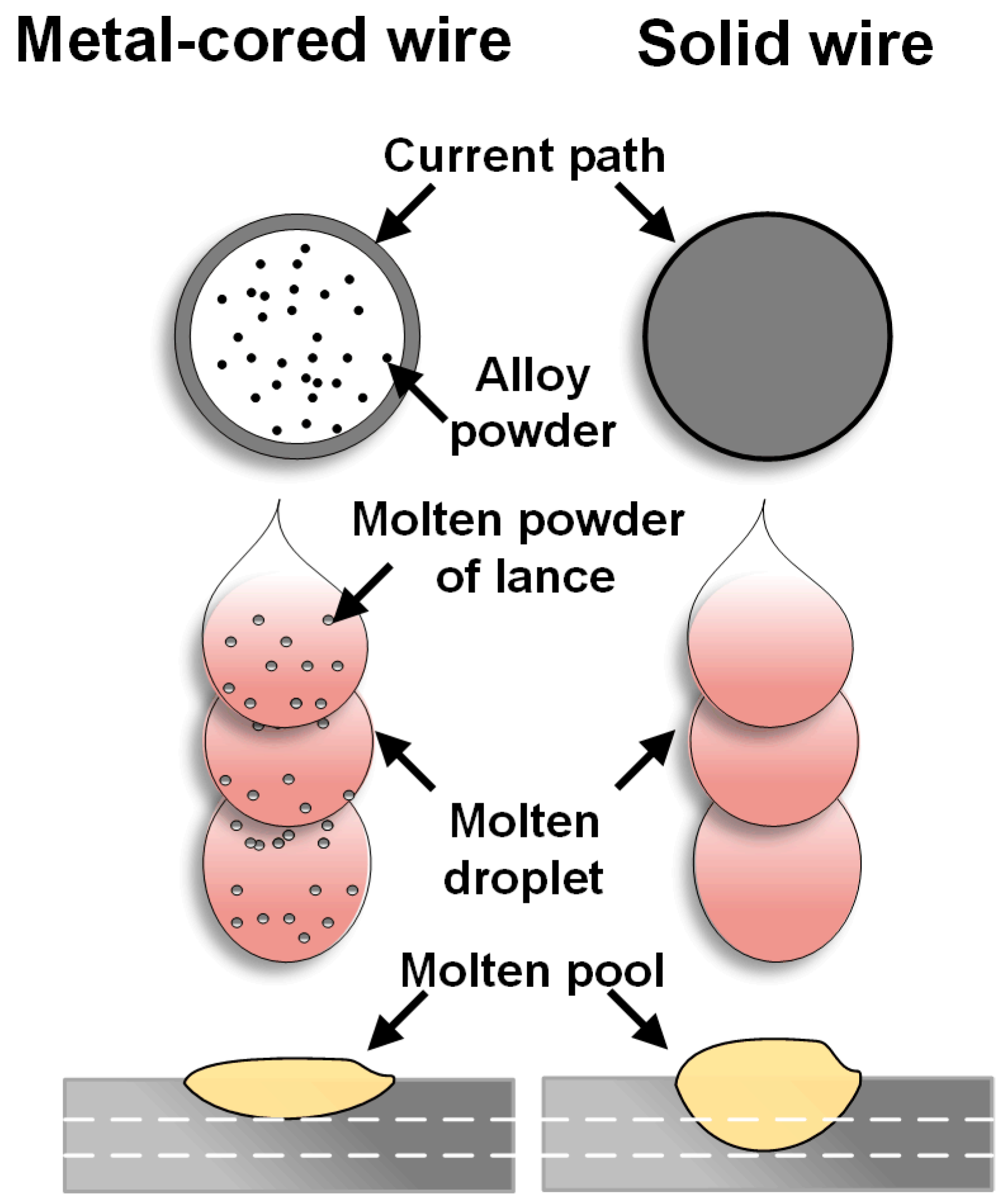
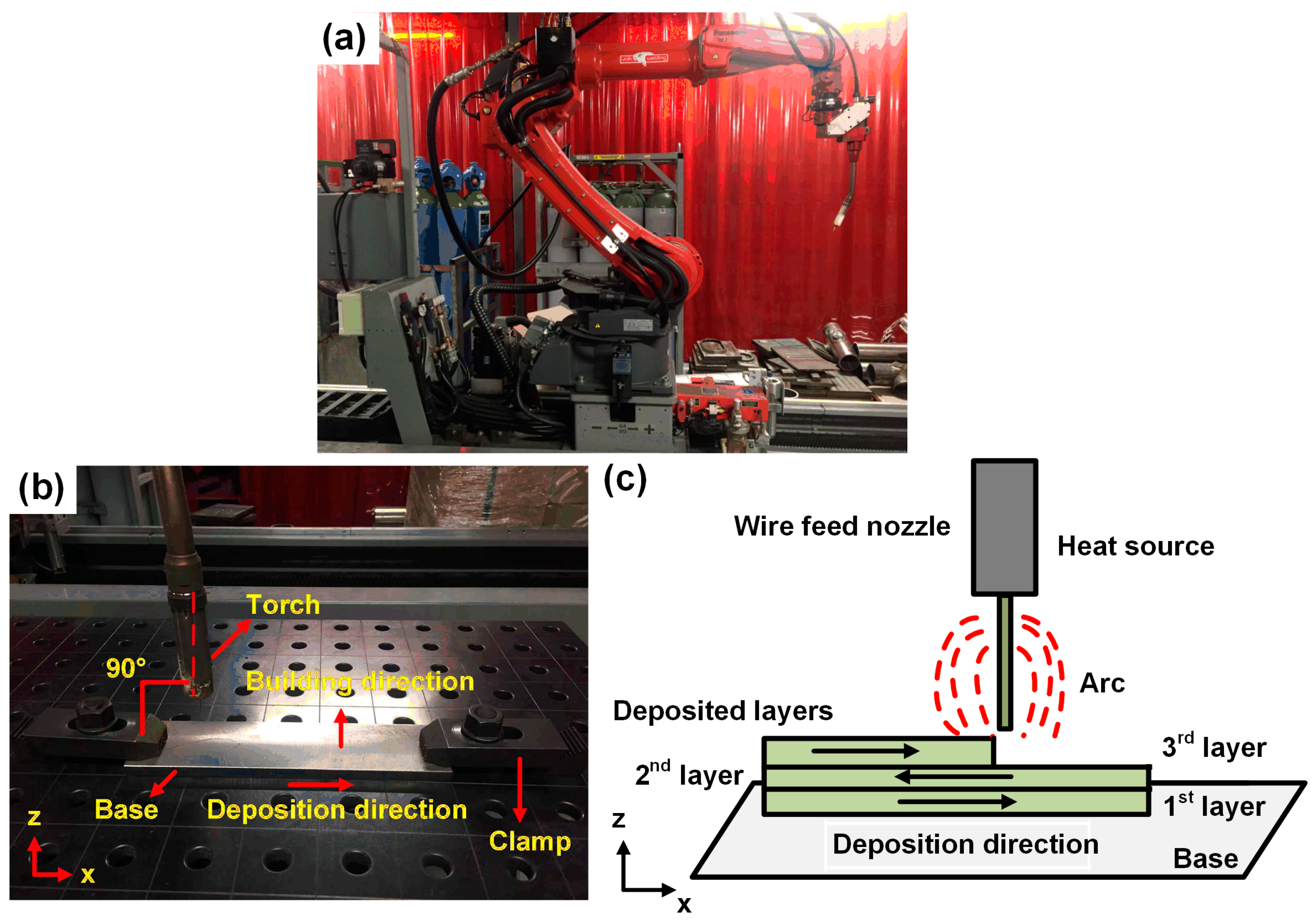
2. Materials and Methods

In this study, S355 structural steel [19] base plate of 250 × 60 × 10 mm3 was used. XC-45 (standard AFNOR, NF A37-502) metal-cored wire with a diameter of 1.2 mm was employed as filler material. The chemical compositions of the materials used in this study are listed in Table 1. For the XC-45, the chemical composition referring to the composition of the deposited metal was measured by optical emission spectroscopy (OES). Prior to deposition, the base surface was cleaned with an acetone ((CH3)2CO) solution.
The deposition was carried out using a Panasonic robotic arm (Figure 2a) and a power source integrated by Valk Welding. The software used for designing the deposition tool path was Autodesk PowerMill (Autodesk B.V, Hoofddorp, The Netherlands). The experimental arrangement in this study is shown in Figure 2b, indicating the deposition direction, the build direction, and the positioning of the clamps. The torch was positioned perpendicular to the workpiece (PA position). The deposition strategy, i.e., reversing the deposition direction for each layer as shown in Figure 2c, was applied to avoid a height difference between the start and stop zones. A parametric experiment was carried out by ramping up the wire feed rate [20] (4–8 m/min) to select optimal deposition conditions based on good bead appearance and an appropriate width to height ratio [21]. The reference deposition parameters used in this research are summarized in Table 2.
Ninety layers were deposited in total and each layer consisted of one bead. After deposition of each layer, the wall was air-cooled until the top surface was measured to be at room temperature, and the contact tip-to-work distance (CTWD) was kept 1 mm higher.
The samples of the as-deposited wall were prepared for metallurgical and mechanical investigations. The prepared cross section was etched by 2% Nital (98% ethanol and 2% HNO3) for optical microscopy (Keyence VHX-5000, Osaka, Japan). The tensile samples were prepared in the vertical and horizontal directions, as shown in Figure 3, according to ASTM E8M-09 standard and tested at room temperature according to the DIN EN 6892-1 standard by means of an Instron-5550 tensile testing machine (Norwood, MA, USA). In addition, fractography was performed using a JEOL JSM-IT100 scanning electron microscope (SEM, Tokyo, Japan). Phase analysis was supported by energy dispersive spectroscopy (EDS). High-resolution microstructural characterization was carried out using a JEOL FEG-SEM JSM 5600F scanning electron microscope (SEM). Vickers hardness (HV2, with 2 kgf) was measured on a cross section of the wall, in the direction from the highest point towards the base, using a Struers DuraScan-70 machine (Struers Inc., Cleveland, OH, USA). The indentation path is shown in Figure 4a.

3. Results and Discussion

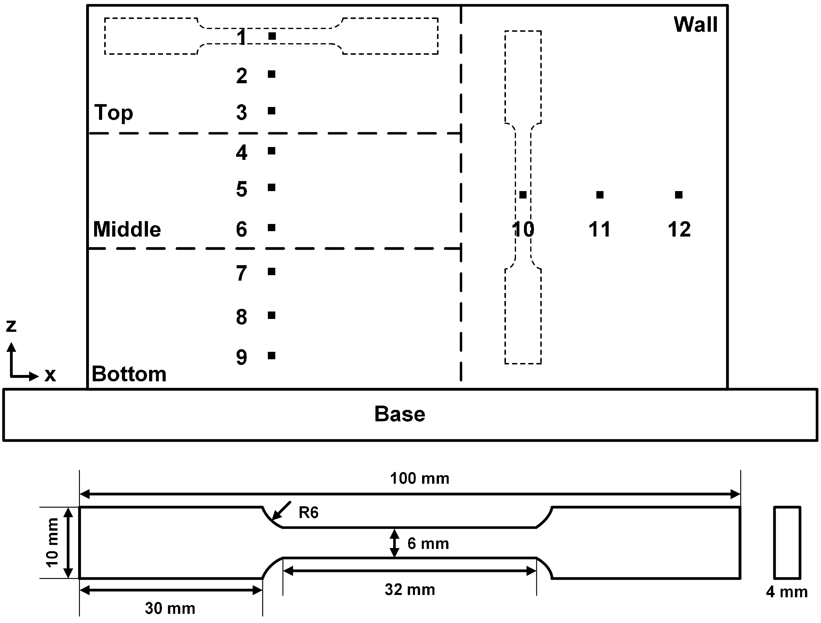
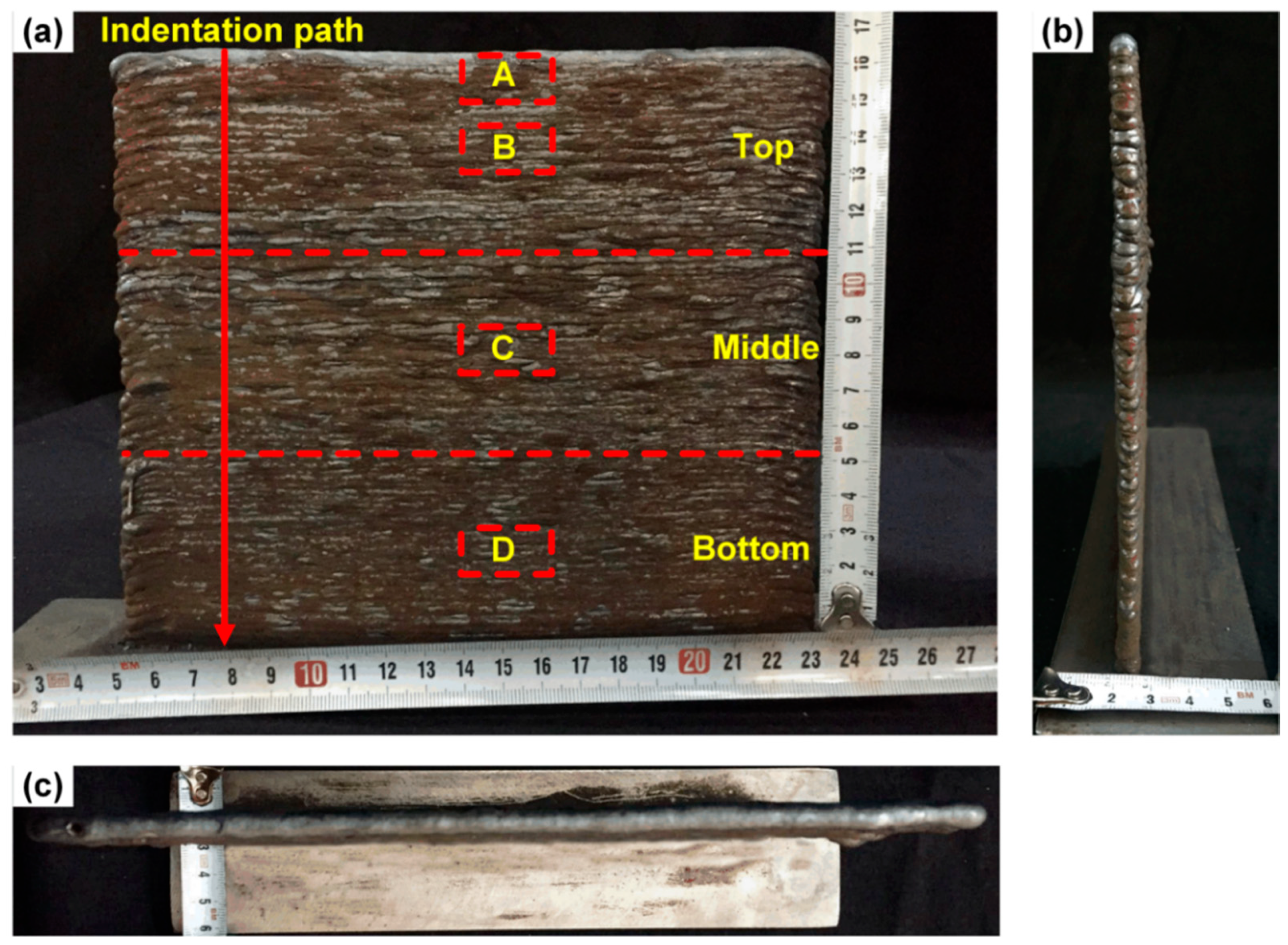
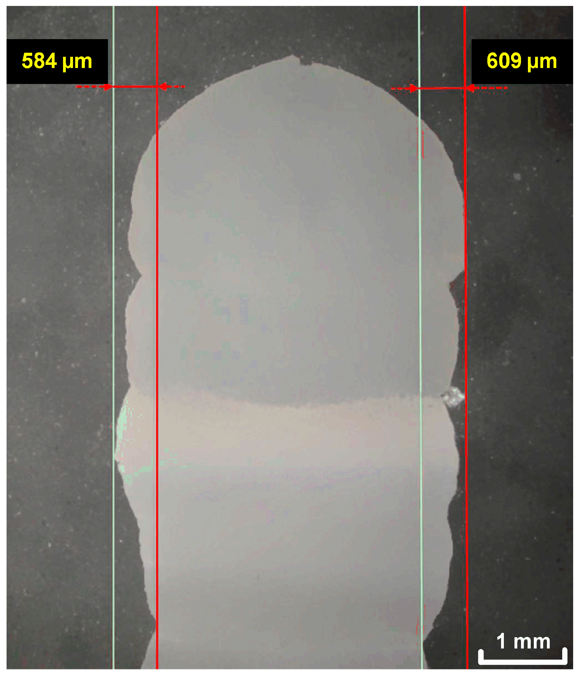
3.1. Macroscopic Inspection

The single bead wall composed of ninety layers is shown in Figure 4. The final dimensions were measured to be around 190 mm in length, 160 mm in height, and 7 mm in width. As seen in Figure 5, the peak-to-valley variation (the distance between the highest and lowest point of the surface) on the top part of the wall was measured to be ~600 μm. The peak-to-valley variation could be caused by bead shape variation due to molten pool instability. It has been reported that higher heat input contributes to decreased surface waviness [22]. Therefore, with the wall building up, the heat input fluctuation in the molten pool caused by the change of heat dissipation condition results in molten pool instability, such as oscillation. In addition, because of the adequate cooling after each layer, the heat accumulation was controlled, so that no significant distortion was noticed for both the base and the wall.

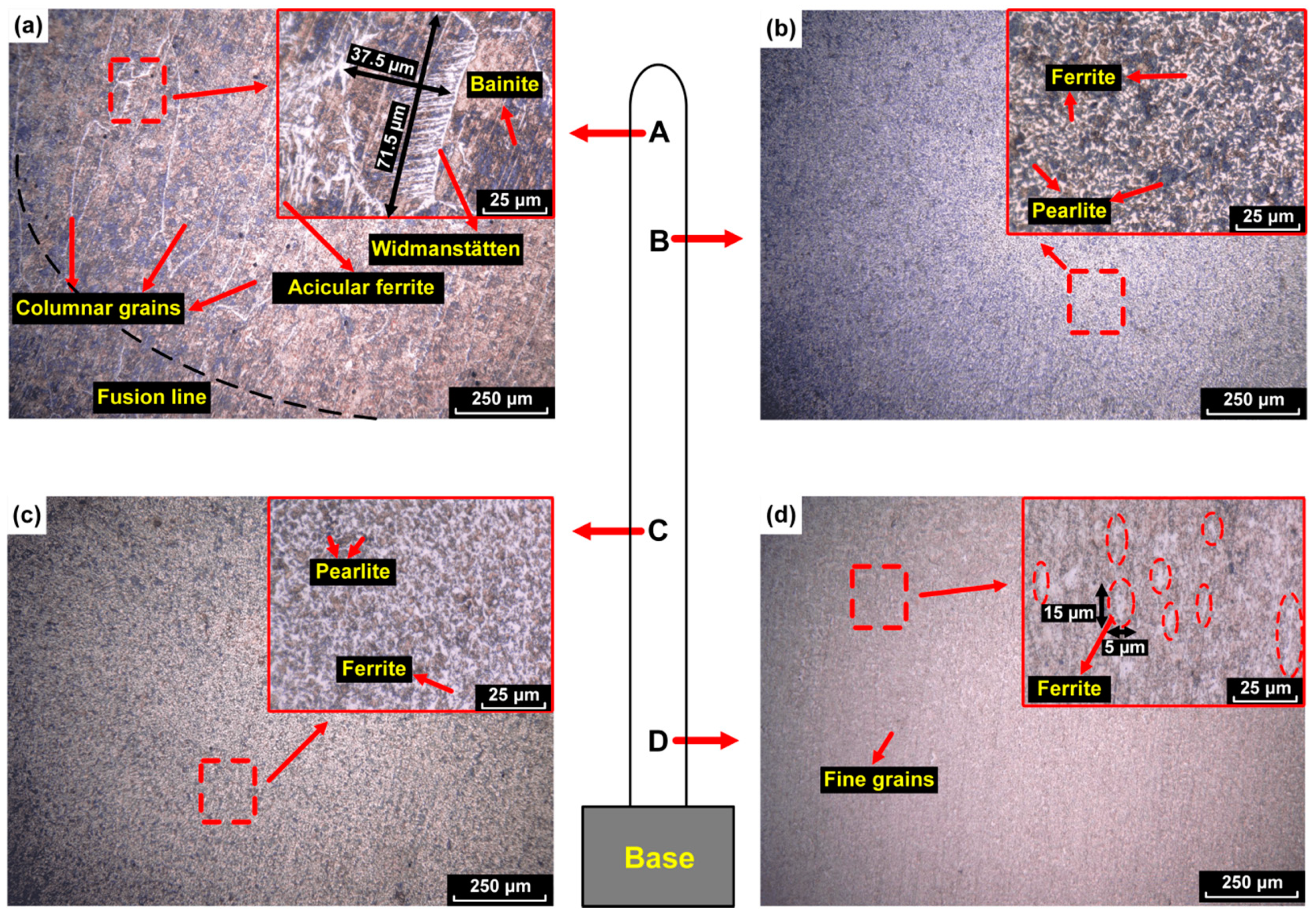
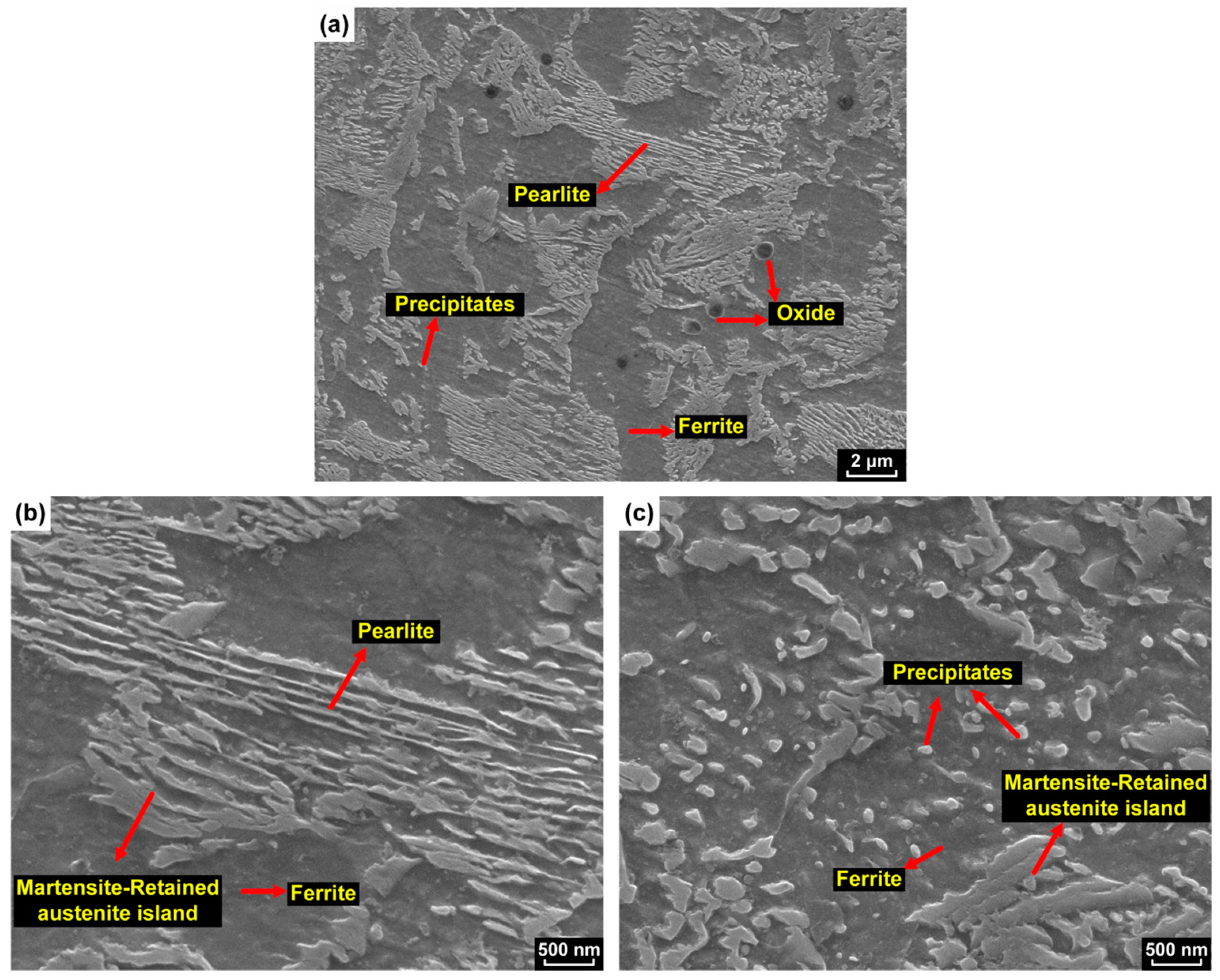
3.2. Microstructure Evolution during WAAM Deposition

The microstructure was investigated at different locations within the WAAM deposited wall (as indicated in Figure 4). Representative etched cross sections at those locations are presented in Figure 6. The cross section revealed the ferrite (white), pearlite (black island), and bainite (black sheaf) phases.
Columnar grains were found at the top of the wall (region A). These columnar grains were directed perpendicular to the fusion line due to the preferential grain growth in the maximum thermal gradient. The prior austenite grains were decorated by grain boundary ferrite. The temperature was measured with a thermocouple at the middle of the deposited track after each layer was deposited, from which the cooling rate was measured by thermocouple to be approximately 85.7 °C/s from 1100 to 800 °C and 28.5 °C/s from 800 to 500 °C.
The microstructures observed by optical microscopy in regions B and C are shown in Figure 6b,c, respectively. From the entire of the two micrographs, it can be seen that the microstructure included ferrite (white) and pearlite (black). The microstructure, in general, became finer from the top to the bottom of the wall.
To have a clearer characterization of the microstructure, a higher resolution micrograph was taken by SEM at region C, which is shown in Figure 7. Some carbide precipitates and oxide particles (black spots in Figure 7a) were found in this region. The pearlite lamellae are shown in Figure 7b and the carbide precipitates are dispersed within the ferrite, as shown in Figure 7c. As seen in Figure 7b, the pearlite lamellae appeared to have thickened and contained edges. This was an indication that during reheating, the pearlite transformed into high carbon austenite, which then transformed to martensite during cooling. This was possible because of the high local hardenability of the carbon enriched austenite. The finest grains were observed in region D, as shown in Figure 6d. The grain size reduction was a result of the multiple thermal cycles experienced by the material. After the multiple thermal cycles, the ferrite and pearlite became finer. This could be proven by the measured maximum width and length of the prior austenite grains in region A and region D. The maximum width/length of the grain decreased from 37.5 µm/71.5 µm in region A to 5 µm/15 µm in region D. It can also be seen that the nucleation of ferrite occurred preferentially at prior columnar austenite grain boundaries.

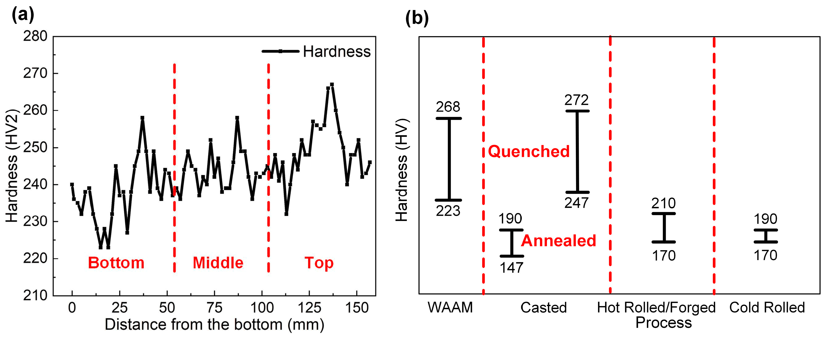
3.3. Hardness of the WAAM Deposited Wall

The variation of hardness along the vertical direction of the deposited wall is plotted in Figure 8a. In general, the deposited material undergoes several thermal cycles, which is expected to affect the hardness [23,24]. In the present case, the average measured hardness of bottom, middle, and top regions were 238 ± 8 HV, 243 ± 5 HV, and 250 ± 4 HV, respectively. The hardness of the top layers was slightly higher than the bottom layers because of the presence of non-equilibrium phases such as bainite and Widmanstätten ferrite, as seen in Figure 6a. The measured hardness (Figure 8a) showed that the fluctuation of hardness in the middle region was the smallest, while that of the top and bottom regions was higher. This indicated that the mechanical properties within the middle region were suspected to be more uniform.
A combination of microstructural factors affects hardness values. In the present case, the hardness depended on the local phase constituents, the grain size, and the fraction and size of the precipitates. The phases present could exhibit a hardness variation due to their exposure to high temperatures. High-temperature exposure induced tempering, recovery, and recrystallization effects, which decreased the hardness, while at the same time, precipitation of carbides and martensitic transformation contributed to a hardness increase. These effects were different along the build direction, as it was largely dependent on the cooling rate and the number of subsequent heat cycles that each layer was exposed to. Therefore, three different zones were distinguished:
(a)
The lower part of the wall, region D. In this region the cooling rate was influenced by the base. The lower regions experienced the highest number of re-heating cycles due to the subsequent layers. Additionally, the composition of the first layers varied slightly, as the dilution of the consumable with the base took place. All these factors were expected to contribute to a lower hardness value and possibly higher elongation in the tensile test.
(b)
The middle part of the wall, regions C and B. In these regions, cooling, apart from convection and radiation, which was similar for all layers, was governed by conduction through the already deposited layers. Therefore, the cooling rate of this region was lower than that of the region D, resulting in a relatively homogeneous hardness. The middle part of the wall also experienced re-heatings, therefore tempering effects also contributed to the mechanical property values. Tempering effects were pronounced in the middle region because there was no influence of the base plate during cooling.
(c)
The top part of the wall, region A. This was the last deposited section of the wall, in which the cooling rate was as in the previous case (b), but the number of re-heating cycles experienced to induce significant tempering effects was reduced. Therefore, this region was likely to exhibit higher hardness values.
The hardness of the WAAM deposited wall was compared with the hardness of XC-45 from different manufacturing processes, as shown in Figure 8b. It shows that the WAAM deposited XC-45 metal-cored wire had a comparable hardness with the other processes.

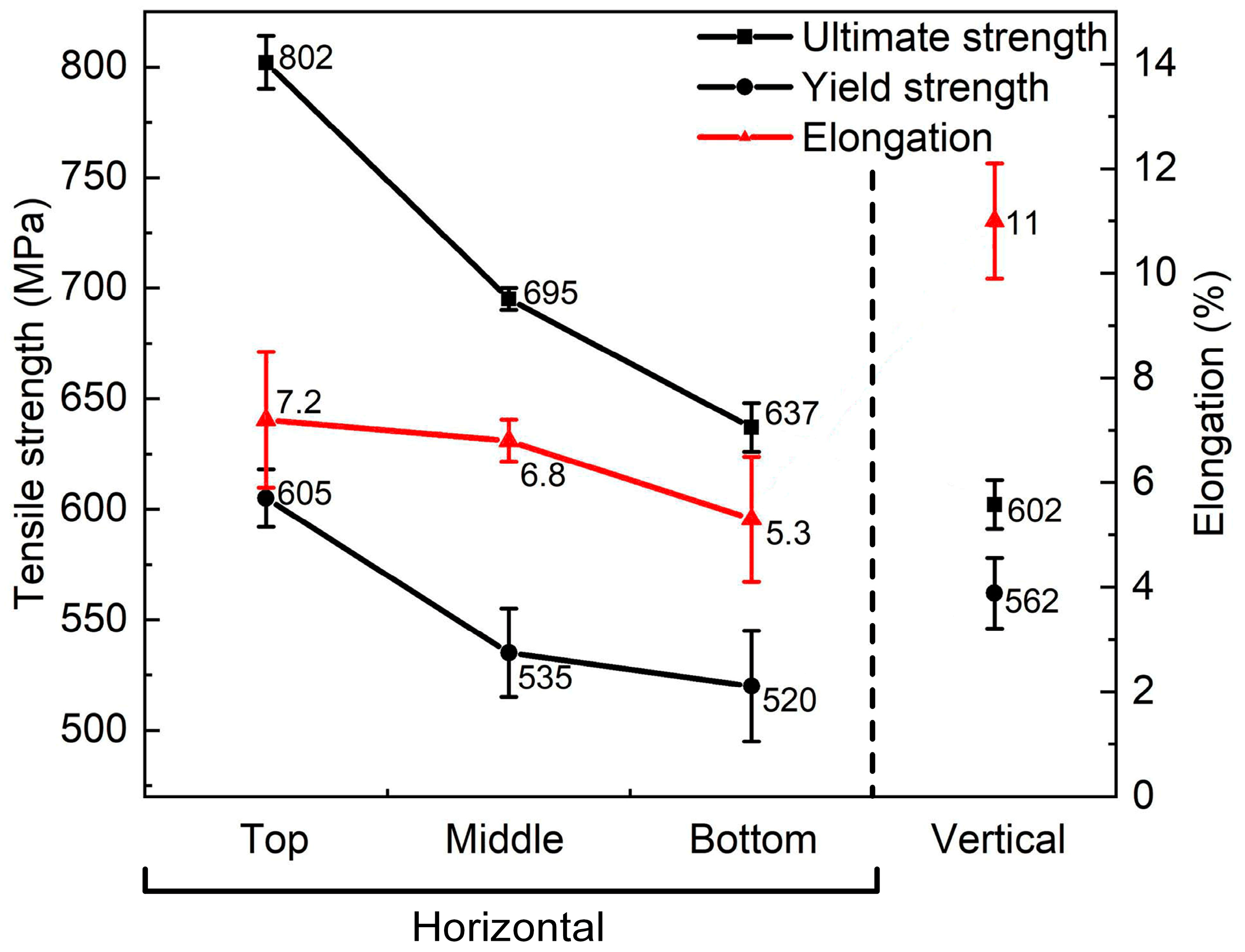
3.4. Tensile Strength Evaluation of the WAAM Deposited Wall
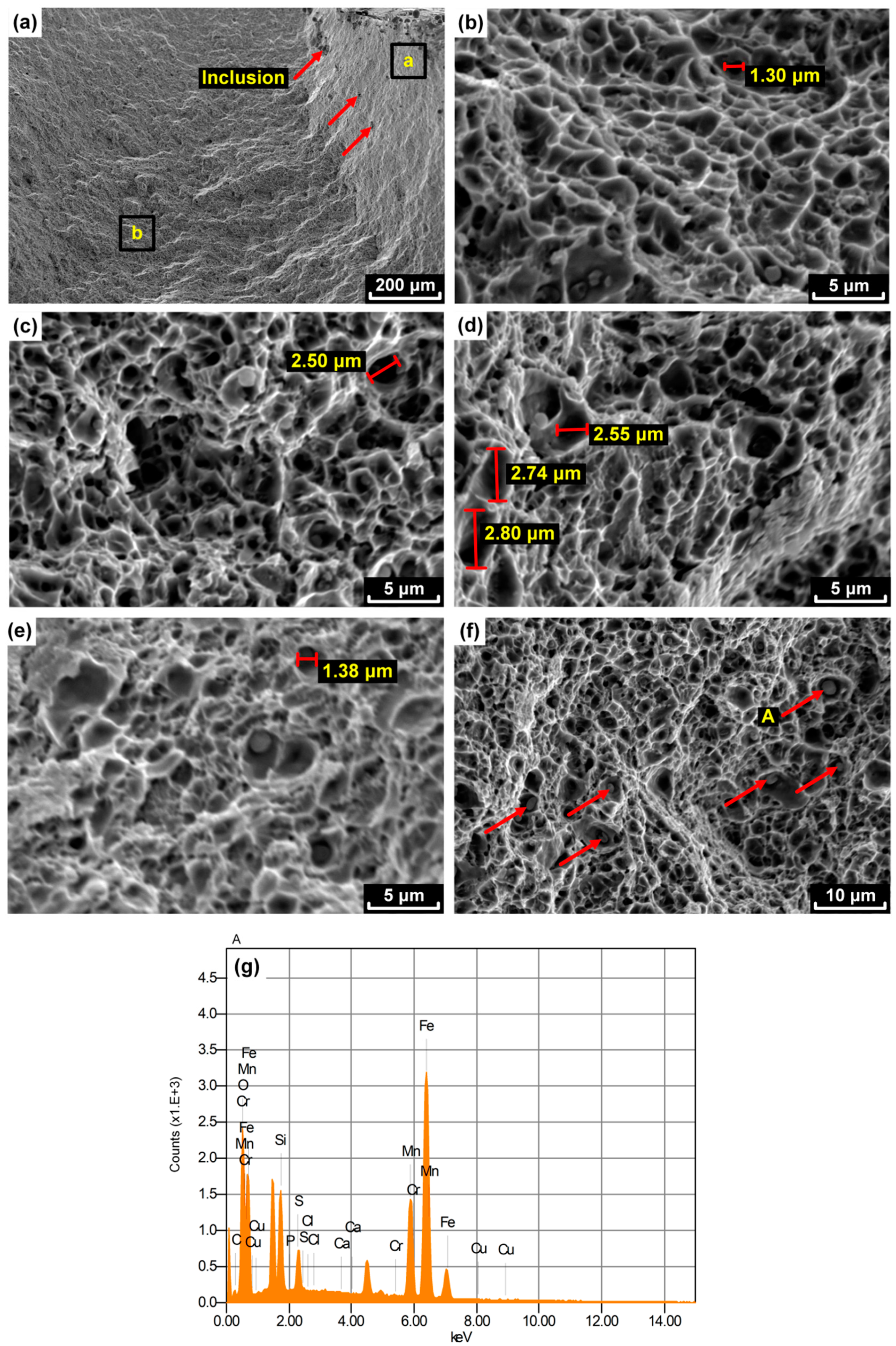
The measured yield and tensile strength together with the elongation of the samples prepared in different directions are summarized in Figure 9. The measurements showed that there was anisotropy in mechanical behavior within the WAAM deposited wall. The tests showed that both yield and ultimate strength decreased from the top to bottom layers. This was in agreement with the hardness profile shown in Figure 8a.
It also can be seen that there was an apparent elongation difference between the horizontal and vertical direction. The existence of ferrite grains nucleated at columnar prior austenite grain boundaries contributed differently to the strength and elongation in the horizontal (deposition) and vertical (build) direction [25]. The anisotropic nature of additive manufactured material properties was also reported by other researchers [26,27].
These average values of the WAAM deposited with XC-45 metal-cored wires were compared with the results of traditional metal processing (based on AISI 1045 steel) methods, which is shown in Figure 10. The yield strength and ultimate strength produced by WAAM were higher than most of the conventional manufacturing methods, while the elongation was lower. This corresponded well with the hardness results presented in Figure 8, which also shows that the average hardness in the quenched condition was higher than for the other techniques. In order to improve the ductility of the XC-45 WAAM deposited material, we considered additional post-deposition heat treatments to acquire the desired ductility. The possible heat treatments for XC-45 WAAM is a topic that was not covered in the current study.

3.5. Fractography

According to the results of tensile test, the samples 3, 6, 8, and 11 (shown in Figure 3) were the samples from the top, middle, bottom, and vertical positions, respectively. Therefore, the fracture surfaces of these tensile samples (number 3, 6, 8, and 11) were observed by means of SEM, as shown in Figure 11. All examined tensile samples showed a non-porous ductile fracture, which was reflected by the dominance of dimples in all fracture surfaces, as seen in Figure 11a. Inclusions were also observed inside dimples. These sites had a higher possibility to nucleate cracks.
Comparing Figure 11b–e, the dimple size in the horizontal samples (numbers 3, 6, and 8) were found to be similar to that in the vertical sample (number 11). Due to the micro-void coalescence effect [28], some large dimples appeared locally.
The particle (A) could be found inside the dimples. The existence of the metallic phases or oxides could promote the formation of dimples. Smaller dimples were probably related to the voids initiating at grain boundaries or other microstructural features. Larger dimples tended to nucleate at oxide particles [29]. Energy-dispersive X-ray spectroscopy (EDX) analyses were performed at particle A (Figure 11f) and the results are shown in Figure 11g. It can be seen that O, Fe, Mn, Cr, Si, and S were the main elements in particle A, which could be identified as either non-metallic inclusion, such as MnS [30] or oxide.

4. Conclusions

The microstructure and mechanical properties of WAAM material deposited with XC-45 metal-cored wires were investigated. Despite the challenging material composition, due to the high carbon content, the deposited wall showed good structural integrity and as-deposited mechanical properties attractive for industrial application. From the study, the following conclusions can be drawn:
(a)
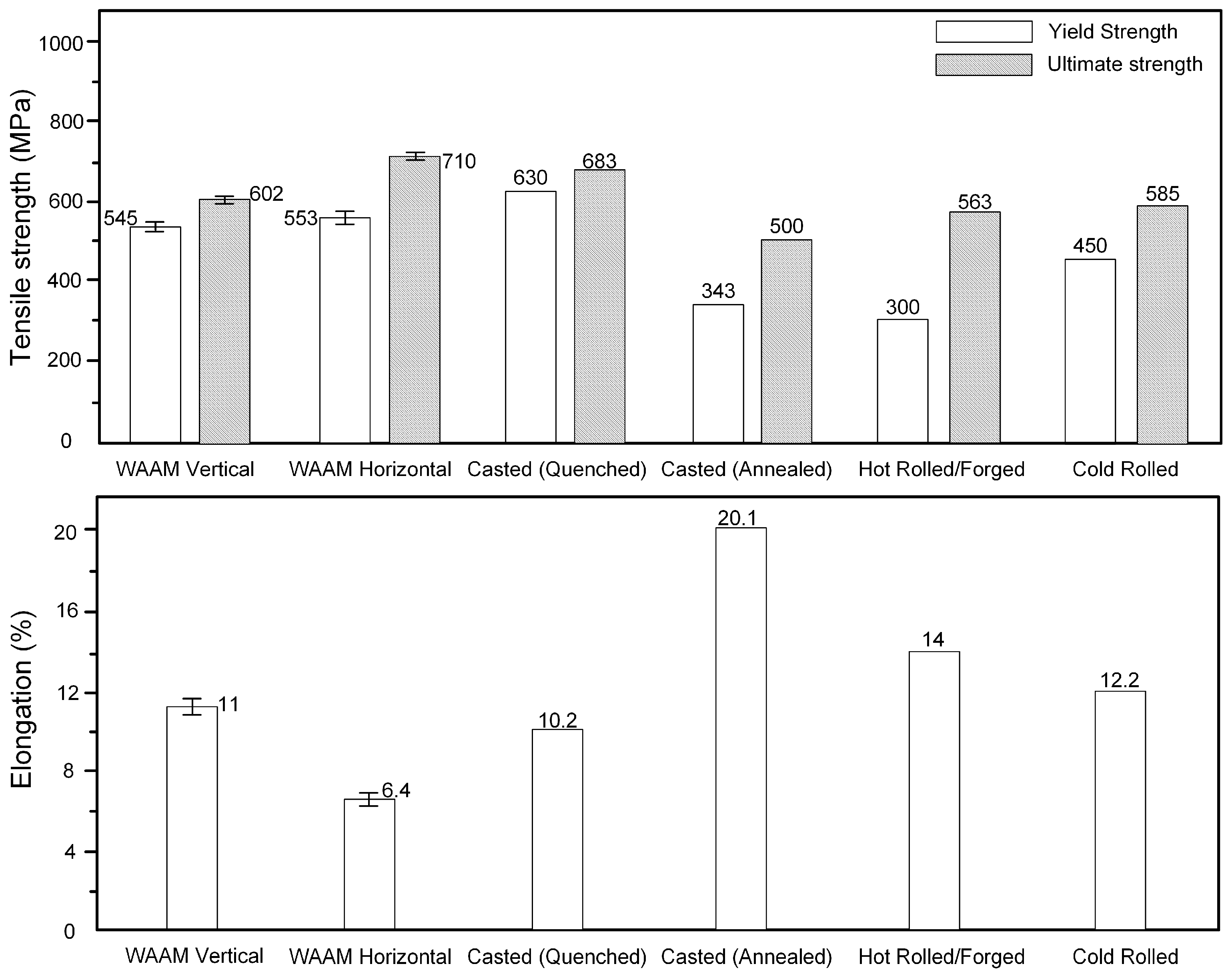
The mechanical properties comparison between WAAM produced XC-45 part and AISI 1045 part produced by traditional processes was carried out. The hardness and tensile strength with WAAM are larger or comparable with the values from the quenched condition.
(b)
The variation of hardness from bottom to the top of the wall is in the range between 223 HV and 268 HV.
(c)
The tensile strength difference exhibits anisotropy between build direction and the horizontal direction, which is around 200 MPa. The mean vertical elongation of the WAAM produced XC-45 wall is 11%, which is higher than 6.4% in the horizontal direction.
(d)
The fracture of the WAAM produced XC-45 wall is ductile. Some particles existing as inclusion, such as MnS or oxide, are found on the fracture surface.
(e)
Pearlite, ferrite, bainite, and martensite are present in the constructed wall. Columnar grains are found near the fusion line. In addition, the repeated thermal cycles cause the grains to become finer from the top to bottom layers.
Based on the results found in this study, it has great potential to apply metal-cored wires in WAAM applications.

Author Contributions

Z.L.: Investigation, formal analysis, writing of the original draft. C.G.: Conceptualization, supervision, writing (review and edit). W.Y.: Conceptualization, supervision, writing (review and edit). M.J.M.H.: Funding acquisition, supervision, writing (review and edit).

Funding

This research was funded by the Dutch organization for scientific research (NWO-Nederlandse Organisatie voor Wetenschappelijk Onderzoek) in the framework of project GradWAAM, Project Number S16043. A special thanks to Mr. Vincent Wegener for providing additional financial support from RAMLAB.

Acknowledgments

This research is carried out under a master project of Delft University of Technology in collaboration with the Rotterdam Fieldlab Additive Manufacturing BV (RAMLAB) www.ramlab.com. The authors would like to express sincere gratitude and thank all researchers from Delft University of Technology and RAMLAB who provided valuable support and input to this research. Lincoln Electric® Europe is acknowledged for manufacturing and providing the metal-cored wires. AirProducts® is acknowledged for the provision of the shielding gas mixture.

Conflicts of Interest

The authors declare no conflict of interest.

References

  1. Guo, N.; Leu, M.C. Additive manufacturing: technology, applications and research needs. Front. Mech. Eng. 2013, 8, 215–243. [Google Scholar] [CrossRef]
  2. ASTM Committee F42 on Additive Manufacturing Technologies. Subcommittee F42. 91 on Terminology. Standard Terminology for Additive Manufacturing Technologies; ASTM International: West Conshohocken, PA, USA, 2012. [Google Scholar]
  3. Williams, S.W.; Martina, F.; Addison, A.C.; Ding, J.; Pardal, G.; Colegrove, P. Wire + arc additive manufacturing. J. Mater. Sci. Technol. 2016, 32, 641–647. [Google Scholar] [CrossRef]
  4. Gu, J.; Ding, J.; Williams, S.W.; Gu, H.; Bai, J.; Zhai, Y.; Ma, P. The strengthening effect of inter-layer cold working and post-deposition heat treatment on the additively manufactured Al–6.3Cu alloy. Mater. Sci. Eng. A 2016, 651, 18–26. [Google Scholar] [CrossRef]
  5. Murr, L.; Gaytan, S.; Ceylan, A.; Martinez, E.; Martínez, J.; Hernandez, D.; Machado, B.; Ramirez, D.; Medina, F.; Collins, S.; et al. Characterization of titanium aluminide alloy components fabricated by additive manufacturing using electron beam melting. Acta Mater. 2010, 58, 1887–1894. [Google Scholar] [CrossRef]
  6. Kim, T.B.; Yue, S.; Zhang, Z.; Jones, E.; Jones, J.R.; Lee, P.D. Additive manufactured porous titanium structures: Through-process quantification of pore and strut networks. J. Mater. Process. Technol. 2014, 214, 2706–2715. [Google Scholar] [CrossRef]
  7. Wang, R.; Beck, F.H. New stainless steel without nickel or chromium for marine applications. Met. Prog. 1983, 123, 74–76. [Google Scholar]
  8. Ding, D.; Pan, Z.; Van Duin, S.; Li, H.; Shen, C.; Requena, G. Fabricating Superior NiAl Bronze Components through Wire Arc Additive Manufacturing. Materials 2016, 9, 652. [Google Scholar] [CrossRef] [PubMed]
  9. Martina, F.; Ding, J.; Williams, S.; Caballero, A.; Pardal, G.; Quintino, L. Tandem metal inert gas process for high productivity wire arc additive manufacturing in stainless steel. Addit. Manuf. 2019, 25, 545–550. [Google Scholar] [CrossRef]
  10. Rodrigues, T.A.; Duarte, V.; Miranda, R.M.; Santos, T.G.; Oliveira, J.P. Current Status and Perspectives on Wire and Arc Additive Manufacturing (WAAM). Materials 2019, 12, 1121. [Google Scholar] [CrossRef]
  11. Guinness World Records 2019. p. 176. Available online: https://www.bruna.nl/boeken/guinness-world-records-2019-9789026146022 (accessed on 8 June 2019).
  12. Frazier, W.E. Metal Additive Manufacturing: A Review. J. Mater. Eng. Perform. 2014, 23, 1917–1928. [Google Scholar] [CrossRef]
  13. Nikodym, A. Flux-Cored Wire Formulation for Welding. U.S. Patent No. 6855913, 15 February 2005. [Google Scholar]
  14. Boothroyd, G.; Dewhurst, P.; Knight, W.A. Product design for manufacture and assembly; M. Dekker: New York, NY, USA, 1994. [Google Scholar]
  15. Klimpel, A.; Dobrzański, L.A.; Janicki, D.; Lisiecki, A. Abrasion resistance of GMA metal cored wires surfaced deposits. J. Mater. Process. Technol. 2005, 164, 1056–1061. [Google Scholar] [CrossRef]
  16. Arivazhagan, B.; Kamaraj, M. Metal-cored arc welding process for joining of modified 9Cr-1Mo (P91) steel. J. Manuf. Process. 2013, 15, 542–548. [Google Scholar] [CrossRef]
  17. Kang, B.Y.; Kim, H.J.; Hwang, S.K. Effect of Mn and Ni on the variation of the microstructure and mechanical properties of low-carbon weld metals. ISIJ Int. 2000, 40, 1237–1245. [Google Scholar] [CrossRef]
  18. Gualco, A.; Svoboda, H.G.; Surian, E.S.; De Vedia, L.A. Effect of welding procedure on wear behaviour of a modified martensitic tool steel hardfacing deposit. Mater. Des. 2010, 31, 4165–4173. [Google Scholar] [CrossRef]
  19. Corus. European Structural Steel Standard EN 10025-2:2004. Available online: https://www.tf.uni-kiel.de/matwis/amat/iss/kap_9/articles/en_steel_standards.pdf (accessed on 8 June 2019).
  20. Ya, W.; Pathiraj, B.; Liu, S. 2D modelling of clad geometry and resulting thermal cycles during laser cladding. J. Mater. Process. Technol. 2016, 230, 217–232. [Google Scholar] [CrossRef]
  21. Ya, W.; Hernández-Sánchez, J.; Pathiraj, B.; Veld, A.H.i.t. A study on attenuation of a Nd: YAG laser power by co-axial and off-axial nozzle powder stream during cladding. In Proceedings of the International Congress on Applications of Lasers & Electro-Optics, Miami, FL, USA, 6 October 2013; pp. 453–462. [Google Scholar]
  22. Rodrigues, T.A.; Duarte, V.; Avila, J.A.; Santos, T.G.; Miranda, R.M.; Oliveira, J.P. Wire and arc additive manufacturing of HSLA steel: Effect of Thermal Cycles on Microstructure and Mechanical Properties. Addit. Manuf. 2019, 27, 440–450. [Google Scholar] [CrossRef]
  23. Wang, T.; Zhang, Y.; Wu, Z.; Shi, C. Microstructure and properties of die steel fabricated by WAAM using H13 wire. Vacuum 2018, 149, 185–189. [Google Scholar] [CrossRef]
  24. Haden, C.V.; Zeng, G.; Carter III, F.M.; Ruhl, C.; Krick, B.A.; Harlow, D.G. Wire and arc additive manufactured steel: Tensile and wear properties. Addit. Manuf. 2017, 16, 115–123. [Google Scholar] [CrossRef]
  25. Ling-kang, J.; Yang, L.; Li, M.; He-lin, L. Analysis of Microstructure and Orientation in X80 Line Pipe Steels. J. Iron. Steel Res. Int. 2011, 18, 664–668. [Google Scholar]
  26. Carroll, B.E.; Palmer, T.A.; Beese, A.M. Anisotropic tensile behavior of Ti–6Al–4V components fabricated with directed energy deposition additive manufacturing. Acta Mater. 2015, 87, 309–320. [Google Scholar] [CrossRef]
  27. Casati, R.; Lemke, J.; Vedani, M. Microstructure and Fracture Behavior of 316L Austenitic Stainless Steel Produced by Selective Laser Melting. J. Mater. Sci. Technol. 2016, 32, 738–744. [Google Scholar] [CrossRef]
  28. Pradhan, P.; Robi, P.; Roy, S.K. Micro void coalescence of ductile fracture in mild steel during tensile straining. Fract. Struct. Integrity 2012, 19, 51–60. [Google Scholar] [CrossRef]
  29. Das, A.; Tarafder, S. Geometry of dimples and its correlation with mechanical properties in austenitic stainless steel. Scr. Mater. 2008, 59, 1014–1017. [Google Scholar] [CrossRef]
  30. He, J.; Lian, J.; Golisch, G.; He, A.; Di, Y.; Münstermann, S. Investigation on micromechanism and stress state effects on cleavage fracture of ferritic-pearlitic steel at −196 °C. Mater. Sci. Eng. A 2017, 686, 134–141. [Google Scholar] [CrossRef]
Figure 1. Comparison of the cross section and the metal transfer mode of a metal-cored wire and solid wire under short-circuit transfer mode.
Metals 09 00673 g001
Figure 2. (a) Robotic wire and arc additive manufacturing (WAAM) set-up, (b) experimental set-up, (c) deposition tool path applied in this study.
Metals 09 00673 g002
Figure 3. Schematic of the tensile test specimens extracted from the WAAM sample.
Metals 09 00673 g003
Figure 4. The single bead wall using XC-45 wire as deposited with WAAM, (a) main view, (b) side view, (c) top view. (under the deposition parameters listed in Table 2).
Metals 09 00673 g004
Figure 5. The local cross section at the top region of the wall (under the deposition parameters listed in Table 2).
Metals 09 00673 g005
Figure 6. Microstructure of XC-45 single bead wall at different locations, (a) region A (close to the wall surface), (b) region B (in the middle of the top region), (c) region C (middle region), (d) region D (bottom region).
Metals 09 00673 g006
Figure 7. High-resolution micrograph of region C, (a) low magnification, (b) high magnification of pearlite, (c) high magnification of precipitates.
Metals 09 00673 g007
Figure 8. (a) Hardness of the XC-45 wall from the bottom to the top, (b) hardness comparison of different processes.
Metals 09 00673 g008
Figure 9. The measured yield strength, ultimate strength, and elongation.
Metals 09 00673 g009
Figure 10. Tensile strength and elongation comparison of different process.
Metals 09 00673 g010
Figure 11. Fractography of tensile samples: (a) low magnification, (b) bottom, (c) middle, (d) top, (e) vertical, (f) energy-dispersive X-ray (EDX) particles, (g) energy dispersive spectroscopy (EDS) plot of particle A (at.%).
Metals 09 00673 g011
Table 1. Chemical composition of the base plate and the welding wire (wt.%).
GradeCSiMnPAlCuFe
AISI S3550.20.551.60.025/0.55balance
XC-450.450.200.800.0110.0150.049balance
Table 2. Reference deposition parameters used in the study.
Current (I)140 (A)
Voltage (U)20.7 (V)
Wire feed speed (WFS)7.15 (m·min−1)
Deposition speed (v)0.35 (m·min−1)
Contact tip-to-work distance (CTWD)0.001 (m)
Gas flow rate (20% He, 12% CO2, 68% Ar)18 (L·min−1)
Wire stickout distance0.015 (m)
Inter-pass temperature298 (K)
Pulse modeNo pulse
Molten droplet transfer modeShort circuiting
PolarityDirect current, reversed polarity
(Wire: positive, base: negative)
Layer height0.00177 (m)

