
Full Ground Ultra-Wideband Wearable Textile Antenna for Breast Cancer and Wireless Body Area Network Applications

 , ,
, ,  , ,
, ,  , and
, and
Abstract
:1. Introduction
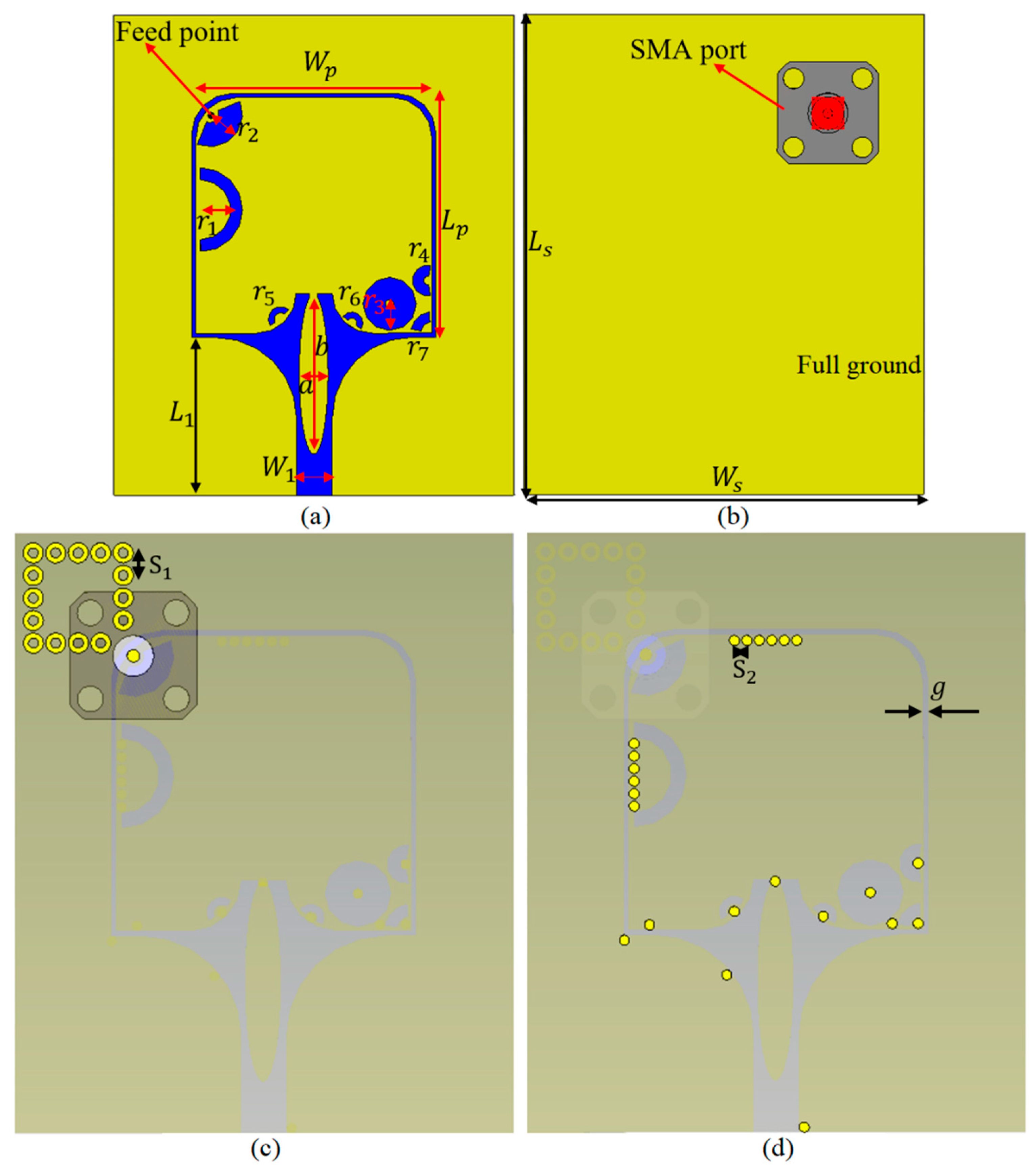
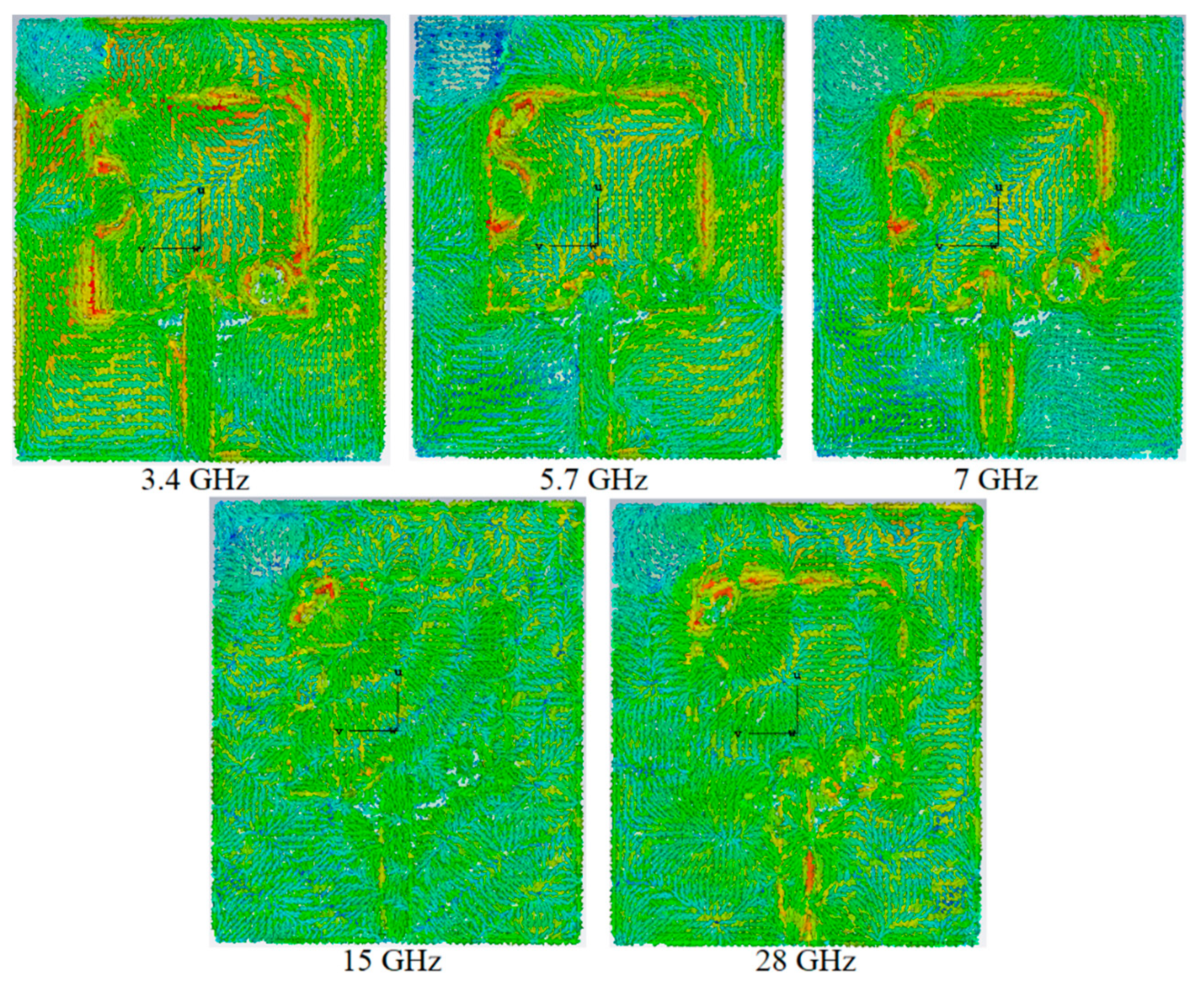
2. Antenna Configuration
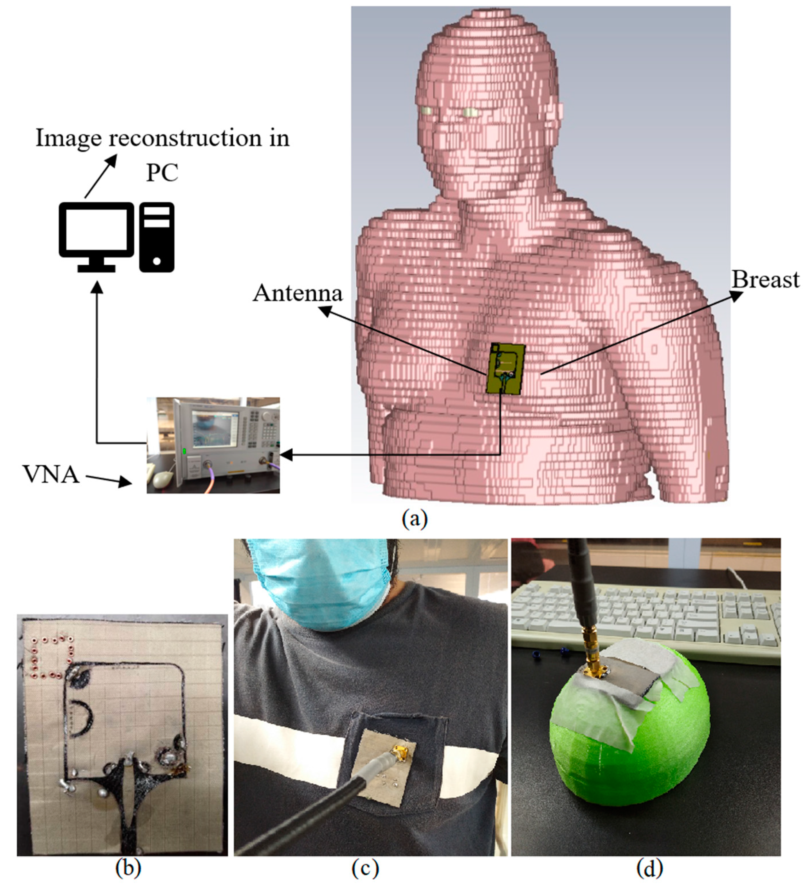
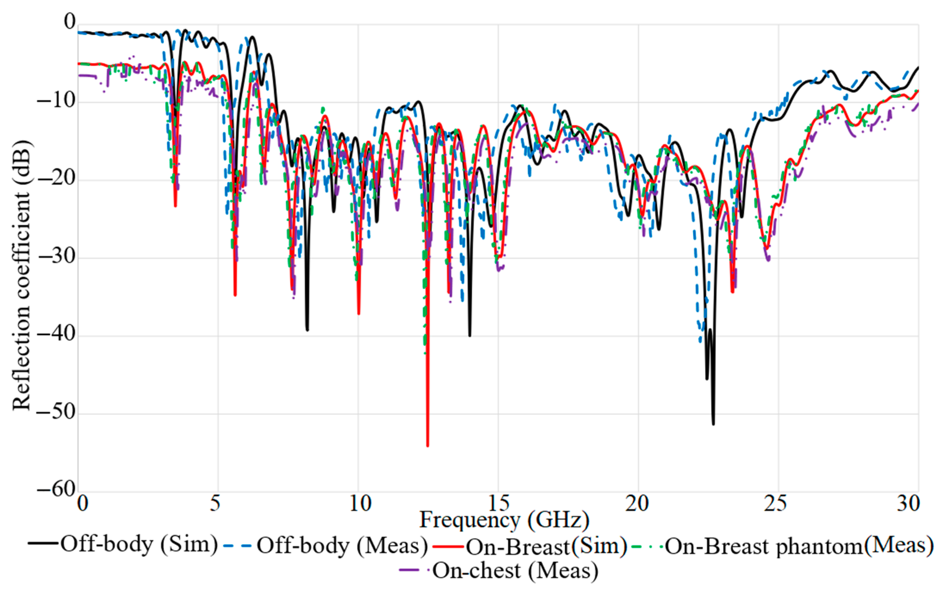
3. Proposed Antenna for On- and Off-Body Conditions
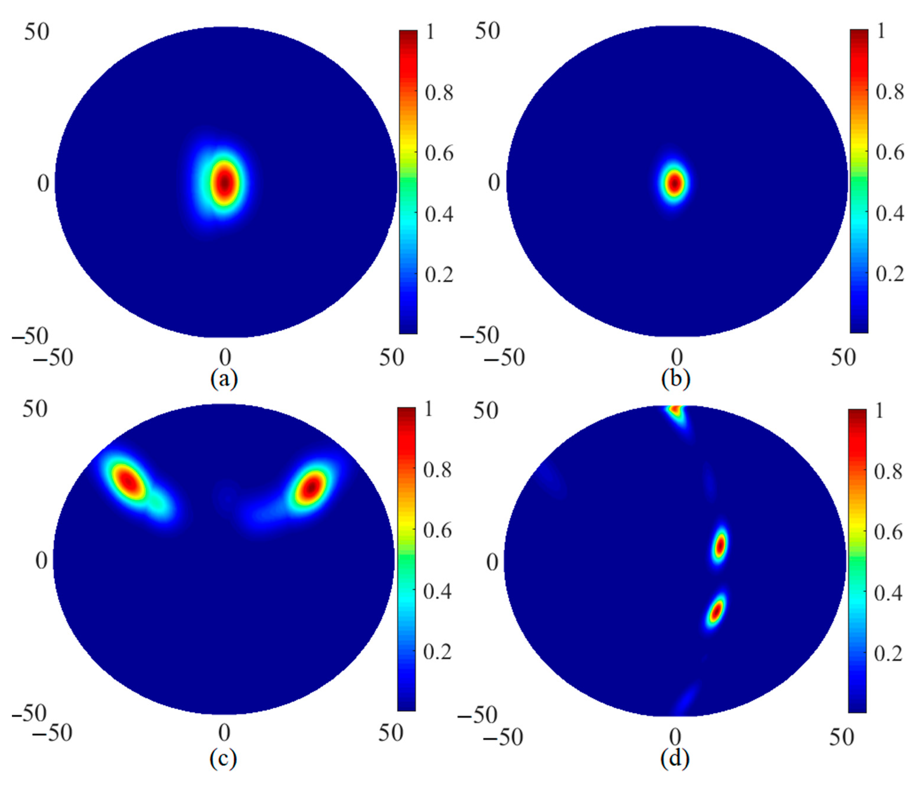
Proposed Antenna’s Capability for Image Reconstruction
4. Conclusions
Author Contributions
Funding
Conflicts of Interest
References
- Alhawari, A.R.H.; Almawgani1, A.H.M.; Hindi, A.T.; Alghamdi, H. Tale Saeidi Metamaterial-based wearable flexible elliptical UWB antenna for WBAN and breast imaging applications. Aip Adv. 2021, 11, 015128. [Google Scholar] [CrossRef]
- Caldeira, J.M.; Rodrigues, J.J.; Lorenz, P. Toward ubiquitous mobility solutions for body sensor networks on healthcare. IEEE Commun. Mag. 2012, 50, 108–115. [Google Scholar] [CrossRef]
- Badhan, K.; Singh, J. Analysis of Different Performance Parameters of Bodywearable Antenna- A Review. Adv. Wirel. Mob. Commun. 2017, 10, 735–745. [Google Scholar]
- Kirtania, S.G.; Elger, A.W.; Hasan, M.R.; Wisniewska, A.; Sekhar, K.; Karacolak, T.; Sekhar, P.K. Flexible Antennas: A Review. Micromachines 2020, 11, 847. [Google Scholar] [CrossRef]
- Al-Sehemi, A.G.; Al-Ghamdi, A.A.; Dishovsky, N.T.; Atanasov, N.T.; Atanasova, G.L. Flexible and small wearable antenna for wireless body area network applications. J. Electromagn. Waves Appl. JEWA 2017, 31, 1063–1082. [Google Scholar] [CrossRef]
- Chen, S.J.; Ranasinghe, D.C.; Fumeaux, C. A robust snap-on button solution for reconfigurable wearable textile antennas. IEEE Trans. Antennas Propag. 2018, 66, 4541–4551. [Google Scholar] [CrossRef]
- Yan, S.; Vandenbosch, G.A. Radiation pattern-reconfigurable wearable antenna based on metamaterial structure. IEEE Antennas Wirel. Propag. Lett. 2016, 15, 1715–1718. [Google Scholar] [CrossRef]
- Kang, S.; Jung, C.W. Wearable fabric reconfigurable beam steering antenna for on/off-body communication system. In Proceedings of the 2015 IEEE International Symposium on Antennas and Propagation & USNC/URSI National Radio Science Meeting, Vancouver, BC, Canada, 19–25 July 2015. [Google Scholar]
- Azeez, H.I.; Yang, H.-C.; Chen, W.-S. Wearable triband E-shaped dipole antenna with low SAR for IoT applications. Electronic 2019, 8, 665. [Google Scholar] [CrossRef] [Green Version]
- Al-Ghamdi, A.A.; Al-Hartomy, O.A.; Al-Solamy, F.R.; Dishovsky, N.T.; Atanasov, N.T.; Atanasova, G.L. Enhancing antenna performance and SAR reduction by a conductive composite loaded with carbon-silica hybrid filler. AEU Int. J. Electron. Commun. 2017, 72, 184–191. [Google Scholar] [CrossRef]
- Saghati, A.P.; Batra, J.S.; Kameoka, J.; Entesari, K. Miniature and reconfigurable CPW folded slot antennas employing liquid-metal capacitive loading. IEEE Trans. Antennas Propag. 2015, 63, 3798–3807. [Google Scholar] [CrossRef]
- Anwar, S.M.; Bangert, A. 3D printed microfluidics-based reconfigurable antenna. In Proceedings of the 2017 IEEE MTT-S International Microwave Workshop Series on Advanced Materials and Processes for RF and THz Applications (IMWS-AMP), Pavia, Italy, 20–22 September 2017. [Google Scholar]
- Wang, C.; Yeo, J.C.; Chu, H.; Lim, C.T.; Guo, Y.X. Design of a reconfigurable patch antenna using the movement of liquid metal. IEEE Antennas Wirel. Propag. Lett. 2018, 17, 974–977. [Google Scholar] [CrossRef]
- Saeed, S.M.; Balanis, C.A.; Birtcher, C.R. A wearable and reconfigurable folded slot antenna for body-worn devices. In Proceedings of the 2017 IEEE International Symposium on Antennas and Propagation & USNC/URSI National Radio Science Meeting, San Diego, CA, USA, 9–15 July 2017. [Google Scholar]
- Kumar, J.; Basu, B.; Talukdar, F.A.; Nandi, A. Graphene-based multimode inspired frequency reconfigurable user terminal antenna for satellite communication. IET Commun. 2017, 12, 67–74. [Google Scholar] [CrossRef]
- Tong, X.; Liu, C.; Liu, X.; Guo, H.; Yang, X. Dual-band on-/off-body reconfigurable antenna for wireless body area network (WBAN) applications. Microw. Opt. Technol. Lett. 2018, 60, 945–951. [Google Scholar] [CrossRef]
- Jang, T.; Zhang, C.; Youn, H.; Zhou, J.; Guo, L.J. Semitransparent and Flexible Mechanically Reconfigurable Electrically Small Antennas Based on Tortuous Metallic Micromesh. IEEE Trans. Antennas Propag. 2017, 65, 1. [Google Scholar] [CrossRef]
- Simorangkir, R.B.; Yang, Y.; Esselle, K.P.; Zeb, B.A. A method to realize robust flexible electronically tunable antennas using polymer-embedded conductive fabric. IEEE Trans. Antennas Propag. 2017, 66, 50–58. [Google Scholar] [CrossRef]
- Cai, Y.; Qian, Z.; Cao, W.; Zhang, Y. Research on the half complementary split-ring resonator and its application for designing miniaturized patch antenna. Microw. Opt. Technol. Lett. 2015, 57, 2601–2604. [Google Scholar] [CrossRef]
- Saeidi, T.; Ismail, I.; Alhawari, A.R.; Wen, W.P. Near-field and far-field investigation of miniaturized UWB antenna for imaging of wood. AIP Adv. 2019, 9, 035232. [Google Scholar] [CrossRef] [Green Version]
- Gao, G.; Hu, B.; Wang, S.; Yang, C. Wearable planar inverted-F antenna with stable characteristic and low specific absorption rate. Microw. Opt. Technol. Lett. 2018, 60, 876–882. [Google Scholar] [CrossRef]
- Michel, A.; Colella, R.; Casula, G.A.; Nepa, P.; Catarinucci, L.; Montisci, G.; Mazzarella, G.; Manara, G. Design considerations on the placement of a wearable UHF-RFID PIFA on a compact ground plane. IEEE Trans. Antennas Propag. 2018, 66, 3142–3147. [Google Scholar] [CrossRef]
- Yan, S.; Soh, P.J.; Vandenbosch, G.A. Wearable dual-band magneto-electric dipole antenna for WBAN/WLAN applications. IEEE Trans. Antennas Propag. 2015, 63, 4165–4169. [Google Scholar] [CrossRef]
- Moro, R.; Agneessens, S.; Rogier, H.; Dierck, A.; Bozzi, M. Textile microwave components in substrate integrated waveguide technology. IEEE Trans. Microw. Theory Tech. T MTT 2015, 63, 422–432. [Google Scholar] [CrossRef] [Green Version]
- Moro, R.; Agneessens, S.; Rogier, H.; Bozzi, M. Circularly-polarised cavity-backed wearable antenna in SIW technology. IET Microw. Antennas Propag. 2017, 12, 127–131. [Google Scholar] [CrossRef] [Green Version]
- Ashyap, A.Y.; Abidin, Z.Z.; Dahlan, S.H.; Majid, H.A.; Shah, S.M.; Kamarudin, M.R.; Alomainy, A. Compact and low-profile textile EBG-based antenna for wearable medical applications. IEEE Antennas Wirel. Propag. Lett. 2017, 16, 2550–2553. [Google Scholar] [CrossRef] [Green Version]
- Islam, M.R.; Ali, M. A 900 MHz beam steering parasitic antenna array for wearable wireless applications. IEEE Trans. Antennas Propag. 2013, 61, 4520–4527. [Google Scholar] [CrossRef]
- Pinapati, S.P.; Ranasinghe, D.C.; Fumeaux, C. Textile multilayer cavity slot monopole for UHF applications. IEEE Antennas Wirel. Propag. Lett. 2017, 16, 2542–2545. [Google Scholar] [CrossRef]
- Chahat, N.; Zhadobov, M.; Le Coq, L.; Sauleau, R. Wearable endfire textile antenna for on-body communications at 60 GHz. IEEE Antennas Wirel. Propag. Lett. 2012, 11, 799–802. [Google Scholar] [CrossRef]
- Awang, Z.; Mohd Affendi, N.A.; Alias, N.A.L.; Razali, N.A.M. Flexible antennas based on natural rubber. Prog. Electromagn. Res. PIER 2016, 61, 75–90. [Google Scholar] [CrossRef] [Green Version]
- Gupta, B.; Sankaralingam, S.; Dhar, S. Development of wearable and implantable antennas in the last decade: A review. In Proceedings of the 2010 10th Mediterranean Microwave Symposium, Guzelyurt, Turkey, 25–27 August 2010. [Google Scholar]
- Bo, G.; Ren, L.; Xu, X.; Du, Y.; Dou, S. Recent progress on liquid metals and their applications. Adv. Phys. X 2018, 3, 1446359. [Google Scholar] [CrossRef] [Green Version]
- Saghati, A.P.; Batra, J.; Kameoka, J.; Entesari, K. A microfluidically-switched CPW folded slot antenna. In Proceedings of the 2014 IEEE Antennas and Propagation Society International Symposium (APSURSI), Memphis, TN, USA, 6–11 July 2014. [Google Scholar]
- Rano, D.; Hashmi, M. Extremely compact EBG-backed antenna for smartwatch applications in medical body area network. IET Microw. Antennas Propag. 2019, 13, 1031–1040. [Google Scholar] [CrossRef]
- Porter, E.; Bahrami, H.; Santorelli, A.; Gosselin, B.; Rusch, L.A.; Popović, M. A wearable microwave antenna array for time-domain breast tumor screening. IEEE Trans. Med. Imaging. 2016, 35, 1501–1509. [Google Scholar] [CrossRef] [PubMed] [Green Version]
- Bahrami, H.; Porter, E.; Santorelli, A.; Gosselin, B.; Popovic, M.; Rusch, L.A. Flexible sixteen monopole antenna array for microwave breast cancer detection. In Proceedings of the 2014 36th Annual International Conference of the IEEE Engineering in Medicine and Biology Society, Chicago, IL, USA, 26–30 August 2014. [Google Scholar]
- Mumtaz, S.; Bo, A.; Al-Dulaimi, A.; Tsang, K.F. Guest editorial 5G and beyond mobile technologies and applications for industrial IoT (IIoT). IEEE Trans. Ind. Inform. 2018, 14, 2588–2591. [Google Scholar] [CrossRef]
- Sun, H.; Zhang, Z.; Hu, R.Q.; Qian, Y. Wearable communications in 5G: Challenges and enabling technologies. IEEE Veh. Technol. Mag. 2018, 13, 100–109. [Google Scholar] [CrossRef]
- Baker, S.B.; Xiang, W.; Atkinson, I. Internet of things for smart healthcare: Technologies, challenges, and opportunities. IEEE Access 2017, 5, 26521–26544. [Google Scholar] [CrossRef]
- Rahman, N.H.A.; Yamada, Y.; Nordin, M.S.A. Analysis on the Effects of the Human Body on the Performance of Electro-Textile Antennas for Wearable Monitoring and Tracking Application. Materials 2019, 12, 1636. [Google Scholar] [CrossRef] [Green Version]
- Srinivasan, D.; Gopalakrishnan, M. Breast cancer detection using adaptable textile antenna design. J. Med. Syst. 2019, 43, 1–10. [Google Scholar] [CrossRef] [PubMed]
- Alam, M.S.; Misran, N.; Yatim, B.; Islam, M.T. Development of Electromagnetic Band Gap Structures in the Perspective of Microstrip Antenna Design. Int. J. Antennas Propag. 2013, 2013, 22. [Google Scholar] [CrossRef]
- Alsharif, F.; Kurnaz, C. Wearable microstrip patch ultra wide band antenna for breast cancer detection. In Proceedings of the 2018 41st International Conference on Telecommunications and Signal Processing (TSP), Athens, Greece, 4–6 July 2018. [Google Scholar]
- Arif, A.; Zubair, M.; Ali, M.; Khan, M.U.; Mehmood, M.Q. A compact, low-profile fractal antenna for wearable on-body WBAN applications. IEEE Antennas Wirel. Propag. Lett. 2019, 18, 981–985. [Google Scholar] [CrossRef]
- Deslandes, D. Design equations for tapered microstrip-to-substrate integrated waveguide transitions. In Proceedings of the 2010 IEEE MTT-S International Microwave Symposium, Anaheim, CA, USA, 23–28 May 2010. [Google Scholar]
- Deslandes, D.; Wu, K. Single-substrate integration technique of planar circuits and waveguide filters. IEEE Trans. Microw. Theory. Tech. 2003, 51, 593–596. [Google Scholar] [CrossRef]
- Saeidi, T.; Ismail, I.; Mahmood, S.N.; Alani, S.; Alhawari, A.R. Microwave imaging of voids in oil palm trunk applying UWB antenna and robust time-reversal algorithm. J. Sens. 2020, 2020, 8895737. [Google Scholar] [CrossRef]
- Haupt, R.L.; Lanagan, M. Reconfigurable antennas. IEEE Antennas Propag Mag. 2013, 55, 49–61. [CrossRef]
- Simorangkir, R.B.; Kiourti, A.; Esselle, K.P. UWB wearable antenna with a full ground plane based on PDMS-embedded conductive fabric. IEEE Antennas Wirel. Propag. Lett. 2018, 17, 493–496. [Google Scholar] [CrossRef]
- Sim, C.Y.D.; Tseng, C.W.; Leu, H.J. Embroidered wearable antenna for ultrawideband applications. Microw. Opt. Technol. Lett. 2012, 54, 2597–2600. [Google Scholar] [CrossRef]
- Negi, D.; Khanna, R.; Kaur, J. Design and performance analysis of a conformal CPW fed wideband antenna with Mu-Negative metamaterial for wearable applications. Int. J. Microw. Wirel. Technol. 2019, 11, 806–820. [Google Scholar] [CrossRef]
- Ahmed, M.; Ahmed, M.; Shaalan, A. A novel UWB double layer lotus wearable antenna for integration on astronauts spacesuit. In Proceedings of the 2017 Japan-Africa Conference on Electronics, Communications and Computers (JAC-ECC), Egypt, Alexandria, 18–20 December 2017. [Google Scholar]
- Osman, M.A.; Rahim, M.K.A.; Samsuri, N.A.; Elbasheer, M.K.; Ali, M.E. Textile UWB antenna bending and wet performances. Int. J. Antennas Propag. 2012, 2012. [Google Scholar] [CrossRef]


| Parameters (mm) | Values | Parameters (mm) | Values | Parameters (mm) | Values |
|---|---|---|---|---|---|
| 50 | 13 | , | 0.5, 3 | ||
| 60 | 19.75 | , | 3.35, 2.8 | ||
| 29.5 | 1.8 | , | 1.8, 1.4 | ||
| 29.5 | 26 | , | 1.4, 0.7 | ||
| , | 4.5, 1.5 | , | 1.5, 0.75 | 2.76, 1.25 |
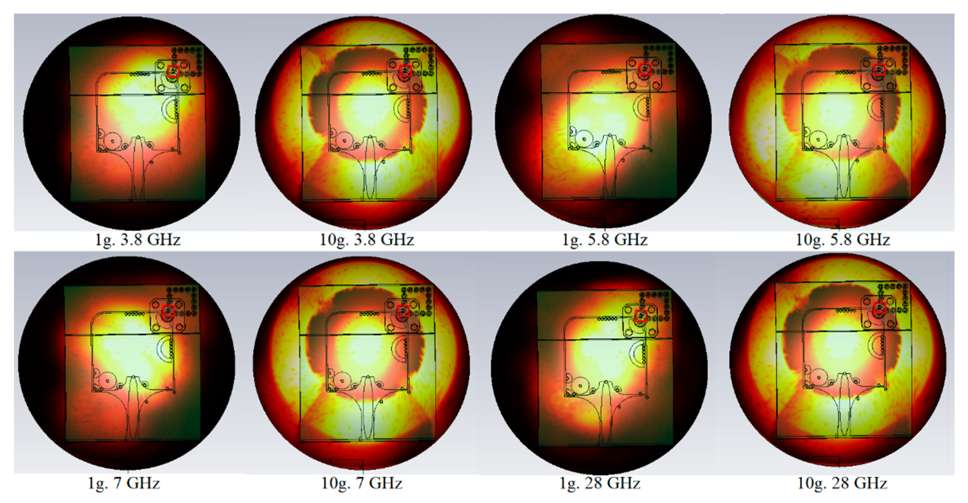
| 3.8 GHz (1 g, 10 g) | 5.8 GHz (1 g, 10 g) | 7 GHz (1 g, 10 g) | 28 GHz (1 g, 10 g) | |
|---|---|---|---|---|
| Values (W/Kg) | 0.25, 0.071 | 0.7, 0.171 | 1.29, 0.520 | 2.04, 0.690 |
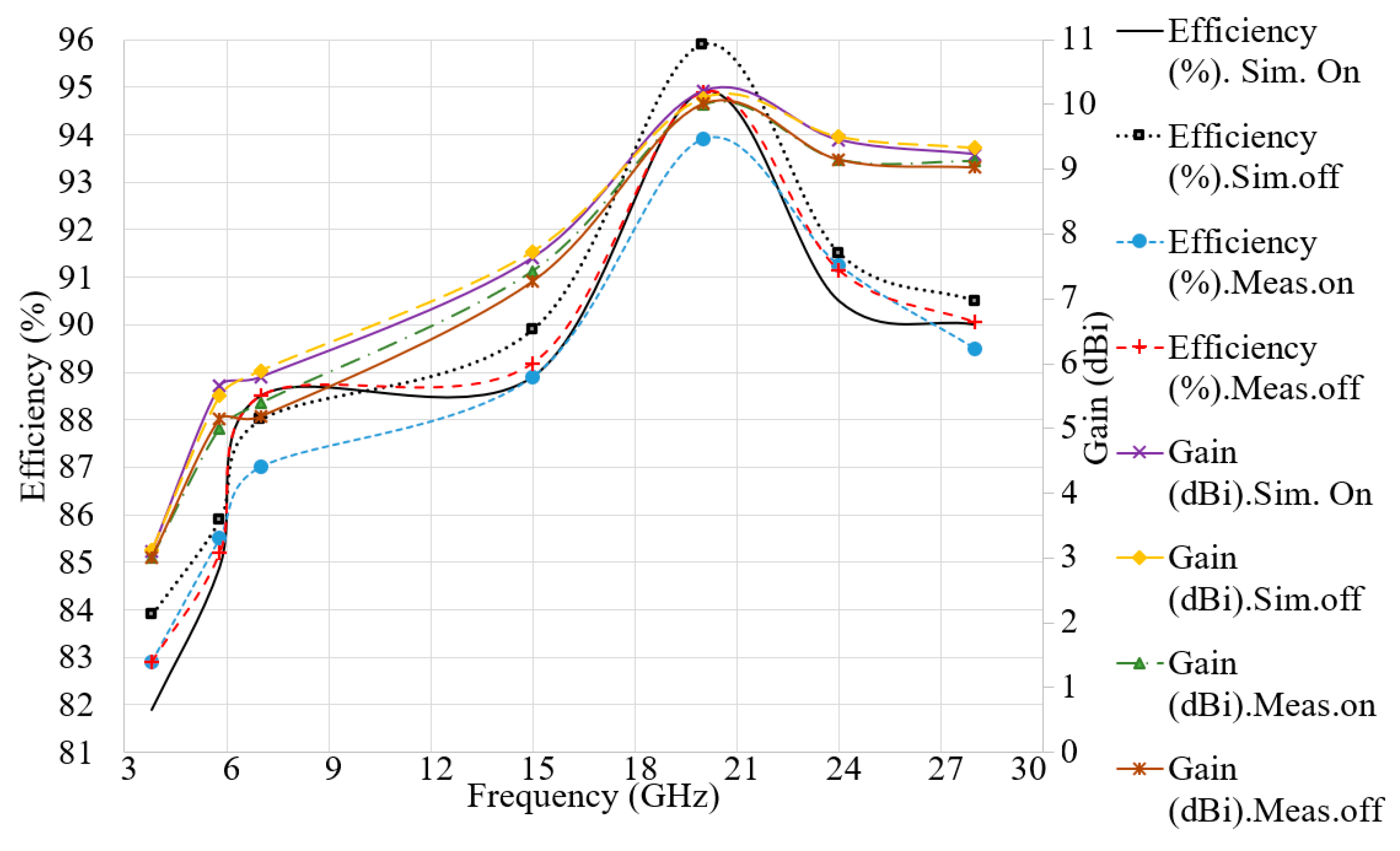
| Parameters/fr (GHz) | Eff (%) Sim. On | Gain (dBi) Sim. On | Eff (%) Sim. off | Gain (dBi) Sim. off | Eff (%) Meas. on | Gain (dBi) Meas. on | Eff (%) Meas. off | Gain (dBi) Meas. off |
|---|---|---|---|---|---|---|---|---|
| 3.8 | 81.90 | 3.10 | 83.90 | 3.12 | 82.90 | 3.00 | 82.90 | 3.01 |
| 5.8 | 84.90 | 5.65 | 85.90 | 5.50 | 85.50 | 5.00 | 85.19 | 5.15 |
| 7 | 88.50 | 5.79 | 88.00 | 5.89 | 87.00 | 5.39 | 88.50 | 5.18 |
| 15 | 88.90 | 7.63 | 89.90 | 7.73 | 88.90 | 7.43 | 89.19 | 7.27 |
| 20 | 94.90 | 10.2 | 95.90 | 10.10 | 93.90 | 10.00 | 94.90 | 10.01 |
| 24 | 90.50 | 9.45 | 91.50 | 9.50 | 91.25 | 9.15 | 91.15 | 9.15 |
| 28 | 90.00 | 9.23 | 90.50 | 9.33 | 89.50 | 9.13 | 90.05 | 9.03 |
| Ref No. | Dimensions (mm) | BW (GHz) | Max Efficiency (%) | Max Gain (dBi) | Feeding Method | Min SAR |
|---|---|---|---|---|---|---|
| [50] | 48 × 39 | 2.7–10.62 | - | 1.8 | CPW | - |
| [49] | 80 × 67 | 3.7–10.3 | <60 | 4.53 | Full GND | 0.09 |
| [51] | 50 × 45 | 2.3–16 | 85 | 8 | CPW | 0.1 |
| [52] | 54 × 54 | 2–12 | - | - | TL | 0.113 |
| [53] | 60 × 60 | 2–15 | 95 | 4 | TL | - |
| Proposed | 60 × 50 | 7–28 | 96 | 10.5 | SIW-GCPW | 0.09 |
Publisher’s Note: MDPI stays neutral with regard to jurisdictional claims in published maps and institutional affiliations. |
© 2021 by the authors. Licensee MDPI, Basel, Switzerland. This article is an open access article distributed under the terms and conditions of the Creative Commons Attribution (CC BY) license (http://creativecommons.org/licenses/by/4.0/).
Share and Cite
Mahmood, S.N.; Ishak, A.J.; Saeidi, T.; Soh, A.C.; Jalal, A.; Imran, M.A.; Abbasi, Q.H. Full Ground Ultra-Wideband Wearable Textile Antenna for Breast Cancer and Wireless Body Area Network Applications. Micromachines 2021, 12, 322. https://doi.org/10.3390/mi12030322
Mahmood SN, Ishak AJ, Saeidi T, Soh AC, Jalal A, Imran MA, Abbasi QH. Full Ground Ultra-Wideband Wearable Textile Antenna for Breast Cancer and Wireless Body Area Network Applications. Micromachines. 2021; 12(3):322. https://doi.org/10.3390/mi12030322
Chicago/Turabian StyleMahmood, Sarmad Nozad, Asnor Juraiza Ishak, Tale Saeidi, Azura Che Soh, Ali Jalal, Muhammad Ali Imran, and Qammer H. Abbasi. 2021. "Full Ground Ultra-Wideband Wearable Textile Antenna for Breast Cancer and Wireless Body Area Network Applications" Micromachines 12, no. 3: 322. https://doi.org/10.3390/mi12030322