
Process Intensification in Bio-Ethanol Production–Recent Developments in Membrane Separation


 ,
,  ,
, 
Abstract
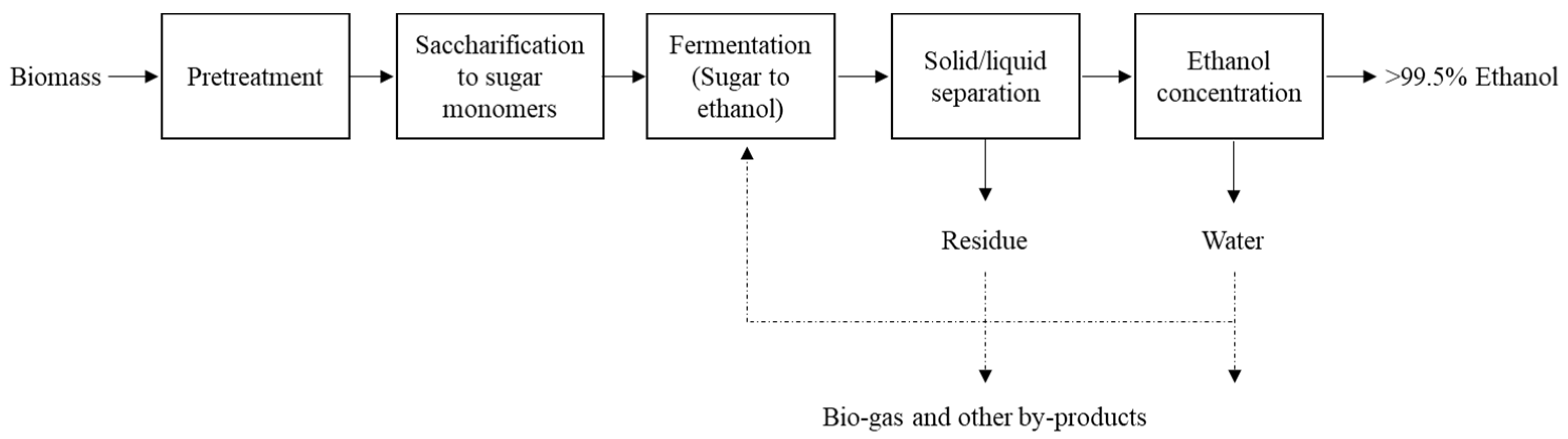
:1. Introduction
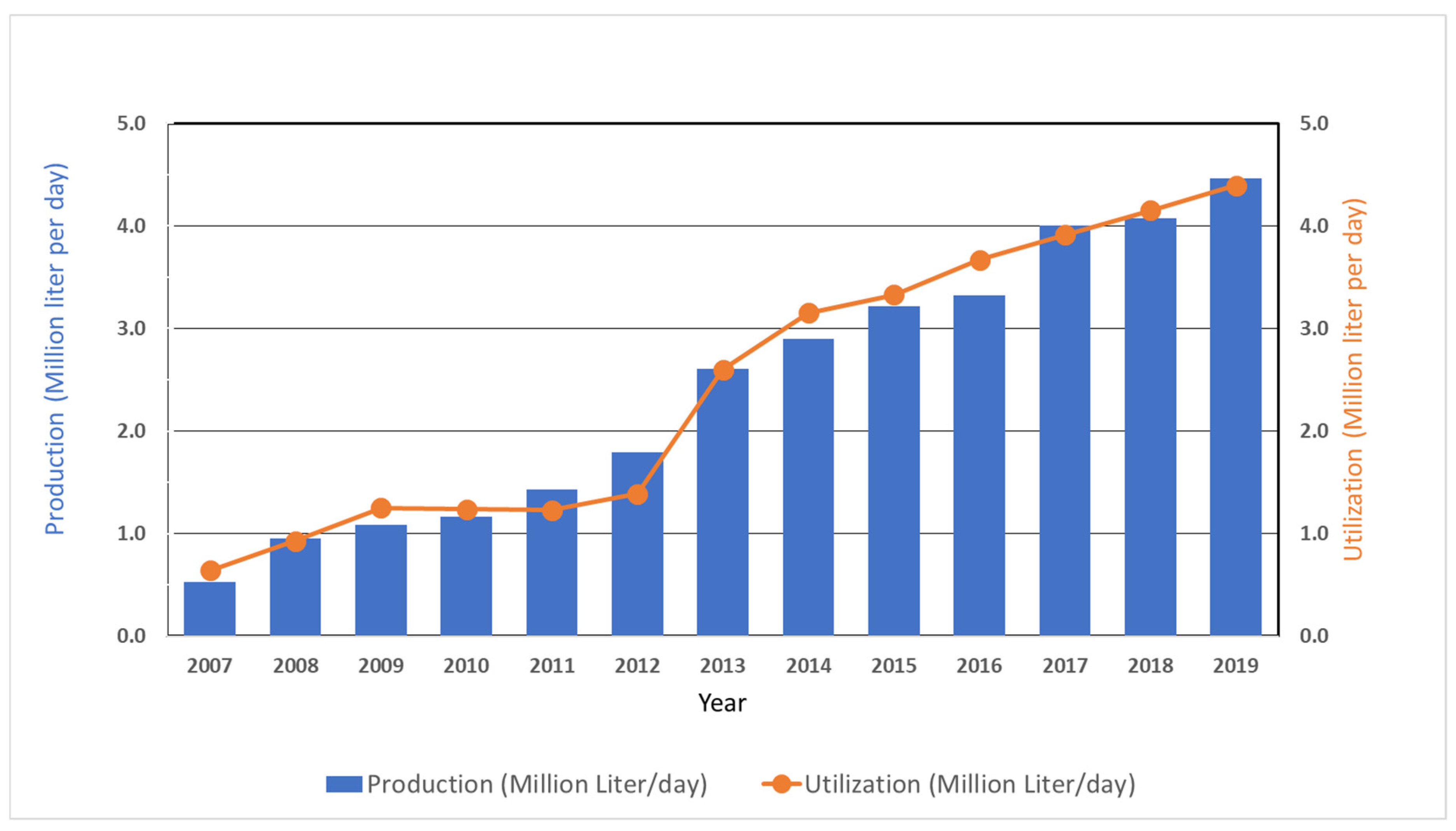
2. Bioethanol Production in Thailand
3. New Approaches on the Microbial Biomass Conversion
4. Various Membrane Separation Processes
5. Combination of Distillation and Water-Selective VP/PV Membranes
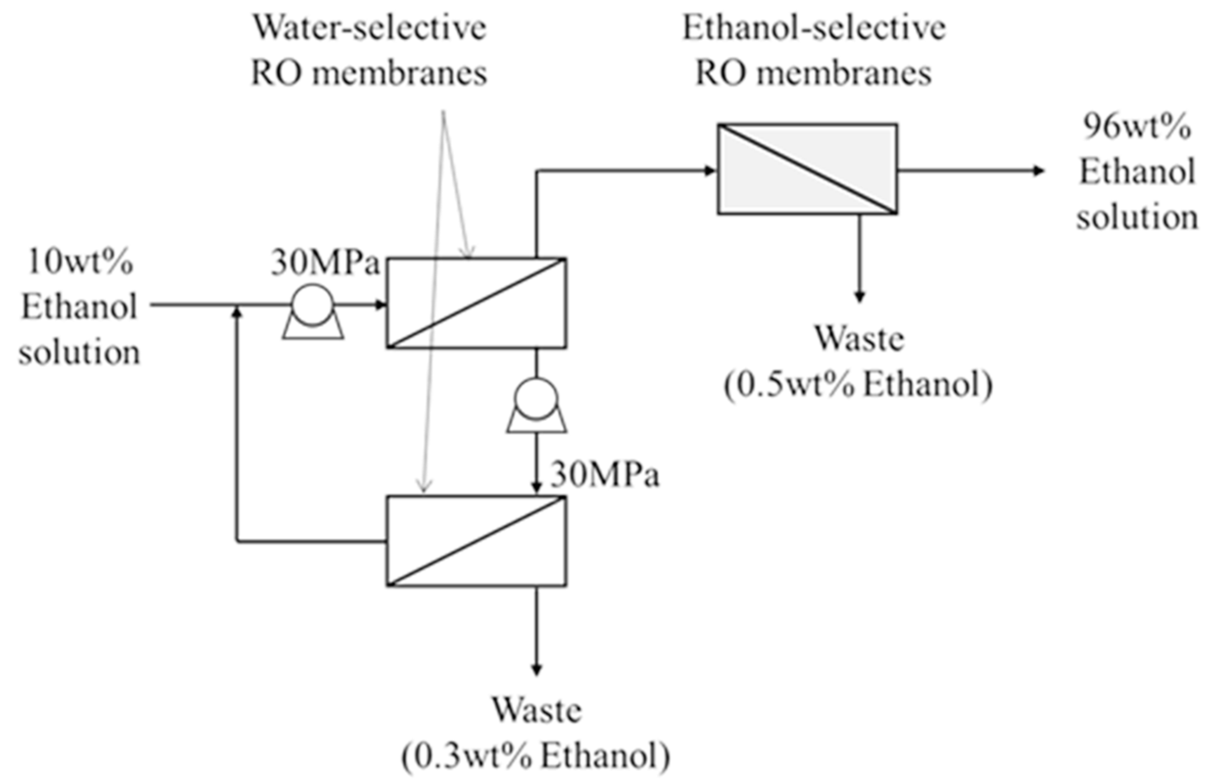
6. Combination of Ethanol-Selective and Water-Selective VP/PV Membranes
7. Ethanol-Selective Silicalite Membranes Applied to a Fermented Solution
8. Conclusions
Author Contributions
Funding
Institutional Review Board Statement
Informed Consent Statement
Data Availability Statement
Conflicts of Interest
References
- Portero Barahona, P.; Bastidas Mayorga, B.; Martín-Gil, J.; Martín-Ramos, P.; Carvajal Barriga, E.J. Cellulosic ethanol: Improving cost efficiency by coupling semi-continuous fermentation and simultaneous saccharification strategies. Processes 2020, 8, 1459. [Google Scholar] [CrossRef]
- Park, J.-H.; Yoon, J.-J.; Park, H.-D.; Lim, D.J.; Kim, S.-H. Anaerobic digestibility of algal bioethanol residue. Bioresour. Technol. 2012, 113, 78–82. [Google Scholar] [CrossRef]
- Pang, B.; Cao, X.-F.; Sun, S.-N.; Wang, X.-L.; Wen, J.-L.; Lam, S.S.; Yuan, T.-Q.; Sun, R.-C. The direct transformation of bioethanol fermentation residues for production of high-quality resins. Green Chem. 2020, 22, 439–447. [Google Scholar] [CrossRef]
- Cesaro, A.; Belgiorno, V. Combined biogas and bioethanol production: Opportunities and challenges for industrial application. Energies 2015, 8, 8121–8144. [Google Scholar] [CrossRef]
- García-Herreros, P.; Gómez, J.M.; Gil, I.D.; Rodríguez, G. Optimization of the design and operation of an extractive distillation system for the production of fuel grade ethanol using glycerol as entrainer. Ind. Eng. Chem. Res. 2011, 50, 3977–3985. [Google Scholar] [CrossRef]
- Karimi, S.; Karri, R.R.; Yaraki, M.T.; Koduru, J.R. Processes and separation technologies for the production of fuel-grade bioethanol: A review. Environ. Chem. Lett. 2021, 1–18. [Google Scholar] [CrossRef]
- Solarte-Toro, J.C.; Romero-García, J.M.; Martínez-Patiño, J.C.; Ruiz-Ramos, E.; Castro-Galiano, E.; Cardona-Alzate, C.A. Acid pretreatment of lignocellulosic biomass for energy vectors production: A review focused on operational conditions and techno-economic assessment for bioethanol production. Renew. Sustain. Energy Rev. 2019, 107, 587–601. [Google Scholar] [CrossRef]
- Alzate, C.C.; Toro, O.S. Energy consumption analysis of integrated flowsheets for production of fuel ethanol from lignocellulosic biomass. Energy 2006, 31, 2447–2459. [Google Scholar]
- Google Scholar. Available online: https://scholar.google.com/ (accessed on 3 June 2021).
- Barros, S. Brazil Biofuels Annual; United States Department of Agriculture (USDA): Washington, DC, USA, 2020.
- Chase, M. China Biofuels Annual; United States Department of Agriculture (USDA): Washington, DC, USA, 2020.
- Ankit, C. India Biofuels Annual; United States Department of Agriculture (USDA): Washington, DC, USA, 2020.
- Prasertsri, P.; Chanikornpradit, M. Thailand Biofuels Annual; United States Department of Agriculture (USDA): Washington, DC, USA, 2020.
- Ryan, B. Philippines Biofuels Annual; United States Department of Agriculture (USDA): Washington, DC, USA, 2020.
- Arif, R. Indonesia Biofuels Annual; United States Department of Agriculture (USDA): Washington, DC, USA, 2020.
- Kokkinos, N.C.; Nikolaou, N.; Psaroudakis, N.; Mertis, K.; Mitkidou, S.; Mitropoulos, A.C. Two-step conversion of LLCN olefins to strong anti-knocking alcohol mixtures catalysed by Rh, Ru/TPPTS complexes in aqueous media. Catal. Today 2015, 247, 132–138. [Google Scholar] [CrossRef]
- Just-Auto.com. Thailand to Replace E10 “Gasohol” with E20 in 2020. Available online: https://www.just-auto.com/news/thailand-to-replace-e10-gasohol-with-e20-in-2020_id193299.aspx (accessed on 19 May 2021).
- Tunapaiboon, N. Ethanol industry. In Thailand Industry Outlook 2019-21; Krungsri Research: Bangkok, Thailand, 2019. [Google Scholar]
- DEDE. Ethanol Data 2007–2017; Department of Alternative Energy Development and Efficiency: Bangkok, Thailand, 2017. [Google Scholar]
- AEDP 2018. Available online: https://www.dede.go.th/download/Plan_62/20201021_TIEB_AEDP2018.pdf (accessed on 3 June 2021).
- Sakchai Preechajarn, P.P.; Maysa, C. Biofuels Annua. Available online: https://apps.fas.usda.gov/newgainapi/api/Report/DownloadReportByFileName?fileName=Biofuels%20Annual_Bangkok_Thailand_11-04-2019 (accessed on 2 June 2020).
- DEDE. Feasibility Study on Cellulosic Ethanol Production in Commercial Scale (In Thai); Ministry of Energy: Bangkok, Thailand, 2012. [Google Scholar]
- Sakachai, P.; Ponnarong, P.; Maysa, C. Thailand Biofules Annual. 2019. Available online: https://apps.fas.usda.gov/newgainapi/api/Report/DownloadReportByFileName?fileName=Biofuels%20Annual_Bangkok_Thailand_11-04-2019 (accessed on 19 May 2021).
- Matsushita, K.; Azuma, Y.; Kosaka, T.; Yakushi, T.; Hoshida, H.; Akada, R.; Yamada, M. Genomic analyses of thermotolerant microorganisms used for high-temperature fermentations. Biosci. Biotechnol. Biochem. 2016, 80, 655–668. [Google Scholar] [CrossRef] [PubMed] [Green Version]
- Kosaka, T.; Lertwattanasakul, N.; Rodrussamee, N.; Nurcholis, M.; Dung, N.T.; Keo-Oudone, C.; Murata, M.; Götz, P.; Theodoropoulos, C.; Maligan, J.M.; et al. Potential of thermotolerant ethanologenic yeasts isolated from ASEAN countries and their application in high-temperature fermentation. Fuel Ethanol Prod. Sugarcane; BoD—Books on Demand: Norderstedt, Germany, 2019; pp. 121–154. [Google Scholar]
- Rodrussamee, N.; Lertwattanasakul, N.; Hirata, K.; Limtong, S.; Kosaka, T.; Yamada, M. Growth and ethanol fermentation ability on hexose and pentose sugars and glucose effect under various conditions in thermotolerant yeast Kluyveromyces marxianus. Appl. Microbiol. Biotechnol. 2011, 90, 1573–1586. [Google Scholar] [CrossRef]
- Charoensopharat, K.; Thanonkeo, P.; Thanonkeo, S.; Yamada, M. Ethanol production from Jerusalem artichoke tubers at high temperature by newly isolated thermotolerant inulin-utilizing yeast Kluyveromyces marxianus using consolidated bioprocessing. Antonie Leeuwenhoek 2015, 108, 173–190. [Google Scholar] [CrossRef]
- Nitiyon, S.; Keo-Oudone, C.; Murata, M.; Lertwattanasakul, N.; Limtong, S.; Kosaka, T.; Yamada, M. Efficient conversion of xylose to ethanol by stress-tolerant Kluyveromyces marxianus BUNL-21. Springerplus 2016, 5, 1–12. [Google Scholar] [CrossRef] [Green Version]
- Yuangsaard, N.; Yongmanitchai, W.; Yamada, M.; Limtong, S. Selection and characterization of a newly isolated thermotolerant Pichia kudriavzevii strain for ethanol production at high temperature from cassava starch hydrolysate. Antonie Leeuwenhoek 2013, 103, 577–588. [Google Scholar] [CrossRef] [PubMed]
- Rodrussamee, N.; Sattayawat, P.; Yamada, M. Highly efficient conversion of xylose to ethanol without glucose repression by newly isolated thermotolerant Spathaspora passalidarum CMUWF1–2. BMC Microbiol. 2018, 18, 1–11. [Google Scholar] [CrossRef] [PubMed]
- Arora, R.; Behera, S.; Sharma, N.K.; Kumar, S. A new search for thermotolerant yeasts, its characterization and optimization using response surface methodology for ethanol production. Front. Microbiol. 2015, 6. [Google Scholar] [CrossRef] [Green Version]
- Talukder, A.A.; Easmin, F.; Mahmud, S.A.; Yamada, M. Thermotolerant yeasts capable of producing bioethanol: Isolation from natural fermented sources, identification and characterization. Biotechnol. Biotechnol. Equip. 2016, 30, 1106–1114. [Google Scholar] [CrossRef] [Green Version]
- Techaparin, A.; Thanonkeo, P.; Klanrit, P. High-temperature ethanol production using thermotolerant yeast newly isolated from Greater Mekong Subregion. Braz. J. Microbiol. 2017, 48, 461–475. [Google Scholar] [CrossRef]
- Prado, C.D.; Mandrujano, G.P.; Souza, J.P.; Sgobbi, F.B.; Novaes, H.R.; da Silva, J.P.; Alves, M.H.; Eliodório, K.P.; Cunha, G.C.; Giudici, R. Physiological characterization of a new thermotolerant yeast strain isolated during Brazilian ethanol production, and its application in high-temperature fermentation. Biotechnol. Biofuels 2020, 13, 1–15. [Google Scholar] [CrossRef] [PubMed]
- Limtong, S.; Sringiew, C.; Yongmanitchai, W. Production of fuel ethanol at high temperature from sugar cane juice by a newly isolated Kluyveromyces marxianus. Bioresour. Technol. 2007, 98, 3367–3374. [Google Scholar] [CrossRef]
- Lertwattanasakul, N.; Kosaka, T.; Hosoyama, A.; Suzuki, Y.; Rodrussamee, N.; Matsutani, M.; Murata, M.; Fujimoto, N.; Tsuchikane, K.; Limtong, S.; et al. Genetic basis of the highly efficient yeast Kluyveromyces marxianus: Complete genome sequence and transcriptome analyses. Biotechnol. Biofuels 2015, 8, 1–14. [Google Scholar] [CrossRef] [PubMed] [Green Version]
- Murata, M.; Nitiyon, S.; Lertwattanasakul, N.; Sootsuwan, K.; Kosaka, T.; Thanonkeo, P.; Limtong, S.; Yamada, M. High-temperature fermentation technology for low-cost bioethanol. J. Jpn. Inst. Energy 2015, 94, 1154–1162. [Google Scholar] [CrossRef] [Green Version]
- Kumar, S.; Singh, N.; Prasad, R. Anhydrous ethanol: A renewable source of energy. Renew. Sustain. Energy Rev. 2010, 14, 1830–1844. [Google Scholar] [CrossRef]
- Khalid, A.; Aslam, M.; Qyyum, M.A.; Faisal, A.; Khan, A.L.; Ahmed, F.; Lee, M.; Kim, J.; Jang, N.; Chang, I.S. Membrane separation processes for dehydration of bioethanol from fermentation broths: Recent developments, challenges, and prospects. Renew. Sustain. Energy Rev. 2019, 105, 427–443. [Google Scholar] [CrossRef]
- Sato, K.; Aoki, K.; Sugimoto, K.; Izumi, K.; Inoue, S.; Saito, J.; Ikeda, S.; Nakane, T. Dehydrating performance of commercial LTA zeolite membranes and application to fuel grade bio-ethanol production by hybrid distillation/vapor permeation process. Microporous Mesoporous Mater. 2008, 115, 184–188. [Google Scholar] [CrossRef]
- Huang, Y.; Baker, R.W.; Vane, L.M. Low-energy distillation-membrane separation process. Ind. Eng. Chem. Res. 2010, 49, 3760–3768. [Google Scholar] [CrossRef]
- Morigami, Y.; Kondo, M.; Abe, J.; Kita, H.; Okamoto, K. The first large-scale pervaporation plant using tubular-type module with zeolite NaA membrane. Sep. Purif. Technol. 2001, 25, 251–260. [Google Scholar] [CrossRef]
- Khayet, M.; Matsuura, T. Pervaporation and vacuum membrane distillation processes: Modeling and experiments. AIChE J. 2004, 50, 1697–1712. [Google Scholar] [CrossRef]
- Hubadillah, S.K.; Tai, Z.S.; Othman, M.H.D.; Harun, Z.; Jamalludin, M.R.; Rahman, M.A.; Jaafar, J.; Ismail, A.F. Hydrophobic ceramic membrane for membrane distillation: A mini review on preparation, characterization, and applications. Sep. Purif. Technol. 2019, 217, 71–84. [Google Scholar] [CrossRef]
- Hietaharju, J.; Kangas, J.; Tanskanen, J. Analysis of the permeation behavior of ethanol/water mixtures through a polydimethylsiloxane (PDMS) membrane in pervaporation and vapor permeation conditions. Sep. Purif. Technol. 2019, 227, 115738. [Google Scholar] [CrossRef]
- Nguyen, T.V.N.; Paugam, L.; Rabiller, P.; Rabiller-Baudry, M. Study of transfer of alcohol (methanol, ethanol, isopropanol) during nanofiltration in water/alcohol mixtures. J. Membr. Sci. 2020, 601, 117907. [Google Scholar] [CrossRef] [Green Version]
- Kumakiri, I.; Yamaguchi, T.; Nakao, S.-i. Application of a zeolite A membrane to reverse osmosis process. J. Chem. Eng. Jpn. 2000, 33, 333–336. [Google Scholar] [CrossRef]
- Holloway, R.W.; Childress, A.E.; Dennett, K.E.; Cath, T.Y. Forward osmosis for concentration of anaerobic digester centrate. Water Res. 2007, 41, 4005–4014. [Google Scholar] [CrossRef]
- Shibuya, M.; Sasaki, K.; Tanaka, Y.; Yasukawa, M.; Takahashi, T.; Kondo, A.; Matsuyama, H. Development of combined nanofiltration and forward osmosis process for production of ethanol from pretreated rice straw. Bioresour. Technol. 2017, 235, 405–410. [Google Scholar] [CrossRef] [PubMed]
- Kataoka, T.; Tsuru, T.; Nakao, S.-I.; Kimura, S. Permeation equations developed for prediction of membrane performance in pervaporation, vapor permeation and reverse osmosis based on the solution-diffusion model. J. Chem. Eng. Jpn. 1991, 24, 326–333. [Google Scholar] [CrossRef] [Green Version]
- Nakao, S. Optimization of membrane process for concentrating alcohol solution. Membrane 1994, 19, 344. [Google Scholar] [CrossRef] [Green Version]
- Li, L.; Dong, J.; Nenoff, T.M.; Lee, R. Desalination by reverse osmosis using MFI zeolite membranes. J. Membr. Sci. 2004, 243, 401–404. [Google Scholar] [CrossRef]
- Lee, K.P.; Arnot, T.C.; Mattia, D. A review of reverse osmosis membrane materials for desalination—development to date and future potential. J. Membr. Sci. 2011, 370, 1–22. [Google Scholar] [CrossRef] [Green Version]
- Kondo, M.; Komori, M.; Kita, H.; Okamoto, K.-I. Tubular-type pervaporation module with zeolite NaA membrane. J. Membr. Sci. 1997, 133, 133–141. [Google Scholar] [CrossRef]
- Sano, T.; Yanagishita, H.; Kiyozumi, Y.; Mizukami, F.; Haraya, K. Separation of ethanol/water mixture by silicalite membrane on pervaporation. J. Membr. Sci. 1994, 95, 221–228. [Google Scholar] [CrossRef]
- Ueno, K.; Negishi, H.; Okuno, T.; Saito, T.; Tawarayama, H.; Ishikawa, S.; Miyamoto, M.; Uemiya, S.; Sawada, Y.; Oumi, Y. High-performance silicalite-1 membranes on porous tubular silica supports for separation of ethanol/water mixtures. Sep. Purif. Technol. 2017, 187, 343–354. [Google Scholar] [CrossRef]
- Ueno, K.; Yamada, S.; Watanabe, T.; Negishi, H.; Okuno, T.; Tawarayama, H.; Ishikawa, S.; Miyamoto, M.; Uemiya, S.; Oumi, Y. Hydrophobic* BEA-type zeolite membranes on tubular silica supports for alcohol/water separation by pervaporation. Membranes 2019, 9, 86. [Google Scholar] [CrossRef] [PubMed] [Green Version]
- Nomura, M.; Bin, T.; Nakao, S.-I. Selective ethanol extraction from fermentation broth using a silicalite membrane. Sep. Purif. Technol. 2002, 27, 59–66. [Google Scholar] [CrossRef]
- CAPE-OPEN to CAPE-OPEN (COCO). Available online: https://www.cocosimulator.org/ (accessed on 19 May 2021).
- Van Hoof, V.; Van den Abeele, L.; Buekenhoudt, A.; Dotremont, C.; Leysen, R. Economic comparison between azeotropic distillation and different hybrid systems combining distillation with pervaporation for the dehydration of isopropanol. Sep. Purif. Technol. 2004, 37, 33–49. [Google Scholar] [CrossRef]
- O’Brien, D.J.; Roth, L.H.; McAloon, A.J. Ethanol production by continuous fermentation–pervaporation: A preliminary economic analysis. J. Membr. Sci. 2000, 166, 105–111. [Google Scholar] [CrossRef]
- Zhu, M.-H.; Kumakiri, I.; Tanaka, K.; Kita, H. Dehydration of acetic acid and esterification product by acid-stable ZSM-5 membrane. Microporous Mesoporous Mater. 2013, 181, 47–53. [Google Scholar] [CrossRef]
- Zhu, M.-H.; Xia, S.-L.; Hua, X.-M.; Feng, Z.-J.; Hu, N.; Zhang, F.; Kumakiri, I.; Lu, Z.-H.; Chen, X.-S.; Kita, H. Rapid preparation of acid-stable and high dehydration performance mordenite membranes. Ind. Eng. Chem. Res. 2014, 53, 19168–19174. [Google Scholar] [CrossRef]
- Zhang, Y.; Qiu, X.; Hong, Z.; Du, P.; Song, Q.; Gu, X. All-silica DD3R zeolite membrane with hydrophilic-functionalized surface for efficient and highly-stable pervaporation dehydration of acetic acid. J. Membr. Sci. 2019, 581, 236–242. [Google Scholar] [CrossRef]
- Claes, S.; Vandezande, P.; Mullens, S.; Leysen, R.; De Sitter, K.; Andersson, A.; Maurer, F.; Van den Rul, H.; Peeters, R.; Van Bael, M. High flux composite PTMSP-silica nanohybrid membranes for the pervaporation of ethanol/water mixtures. J. Membr. Sci. 2010, 351, 160–167. [Google Scholar] [CrossRef]
- Claes, S.; Vandezande, P.; Mullens, S.; De Sitter, K.; Peeters, R.; Van Bael, M.K. Preparation and benchmarking of thin film supported PTMSP-silica pervaporation membranes. J. Membr. Sci. 2012, 389, 265–271. [Google Scholar] [CrossRef]
- Kujawska, A.; Knozowska, K.; Kujawa, J.; Li, G.; Kujawski, W. Fabrication of PDMS based membranes with improved separation efficiency in hydrophobic pervaporation. Sep. Purif. Technol. 2020, 234. [Google Scholar] [CrossRef]
- Naik, P.V.; Kerkhofs, S.; Martens, J.A.; Vankelecom, I.F. PDMS mixed matrix membranes containing hollow silicalite sphere for ethanol/water separation by pervaporation. J. Membr. Sci. 2016, 502, 48–56. [Google Scholar] [CrossRef]
- He, X.; Hägg, M.-B. Membranes for Environmentally Friendly Energy Processes. Membranes 2012, 2, 706–726. [Google Scholar] [CrossRef] [Green Version]
- Caro, J.; Noack, M. Zeolite membranes–status and prospective. In Advances in Nanoporous Materials; Elsevier: New York, NY, USA, 2010; Volume 1, pp. 1–96. [Google Scholar]
- Lin, Y.; Duke, M.C. Recent progress in polycrystalline zeolite membrane research. Curr. Opin. Chem. Eng. 2013, 2, 209–216. [Google Scholar] [CrossRef]
- Zhang, F.; Zheng, Y.; Hu, L.; Hu, N.; Zhu, M.; Zhou, R.; Chen, X.; Kita, H. Preparation of high-flux zeolite T membranes using reusable macroporous stainless steel supports in fluoride media. J. Membr. Sci. 2014, 456, 107–116. [Google Scholar] [CrossRef]
- Nguyen, N.M.; Le, Q.T.; Nguyen, D.P.-H.; Nguyen, T.N.; Le, T.T.; Pham, T.C.-T. Facile synthesis of seed crystals and gelless growth of pure silica DDR zeolite membrane on low cost silica support for high performance in CO2 separation. J. Membr. Sci. 2021, 624, 119110. [Google Scholar] [CrossRef]
- Achiou, B.; Beqqour, D.; Elomari, H.; Bouazizi, A.; Ouammou, M.; Bouhria, M.; Aaddane, A.; Khiat, K.; Younssi, S.A. Preparation of inexpensive NaA zeolite membrane on pozzolan support at low temperature for dehydration of alcohol solutions. J. Environ. Chem. Eng. 2018, 6, 4429–4437. [Google Scholar] [CrossRef]
- Offeman, R.D.; Ludvik, C.N. Poisoning of mixed matrix membranes by fermentation components in pervaporation of ethanol. J. Membr. Sci. 2011, 367, 288–295. [Google Scholar] [CrossRef]


| Country | Production (Million Liters per Day) | Blend Rate in Gasoline (vol%) |
|---|---|---|
| United State | 163.86 | 10.55 |
| Brazil | 89.40 | 27 |
| EU | 14.93 | 6.16 |
| China | 9.33 | 2.4 |
| India | 5.50 | 4.5 |
| Canada | 5.19 | 6.6 |
| Thailand | 4.36 | 13.7 |
| Argentina | 3.01 | 11.7 |
| Membrane Type | Membrane Material | Feed Ethanol Conc. (wt%) | Temperature (K) | Permeate Ethanol Conc. (wt%) * | Separation Factor, α (-) | Flux (Kg m−2 h−1) | Ref. |
|---|---|---|---|---|---|---|---|
| Polymeric membranes | PDMS ǂ (Pervatech, Netherland) | 5 | 323 | 26 | 6.7 ± 1.0 | 2.6 ± 0.4 | [66] |
| PERVAP 4060 (Sulzer Chemtech, Switzerland) | 5 | 323 | 27 | 7.1 ± 1.3 | 1.3 ± 0.3 | [66] | |
| PERVAP 4060 (Sulzer Chemtech, Switzerland) | 5 | 303 | 32 | 9 | 0.6 | [67] | |
| Mixed matrix membranes (MMMs) | PDMS-silicalite hollow spheres (30 wt% **) | 6 | 313 | 49 | 15.3 | 0.07 | [68] |
| PDMS-hydrophobized Al2O3 + (1 wt% **) | 5 | 303 | 37 | 11 | 0.06 | [67] | |
| PTMSP ǂǂ -silica (1.5 wt% **) | 10 | 323 | 63 | 15.3 | 0.40 | [65] | |
| Inorganic membranes | Silicalite | 12 | 333 | 89 | 58 | 0.76 | [55] |
| Silicalite | 10 | 323 | 91 | 92 | 3.00 | [56] | |
| All silica beta-zeolite | 10 | 323 | 58 | 12.3 | 6.29 | [57] |
| Process Configuration | Energy Demand (W/kg-EtOH) | |||
|---|---|---|---|---|
| Feed Treatment | Chiller | Total | ||
| Distillation | - | - | 1803 | |
| Membrane separation | Vacuum at the permeate side | 906 | 956 | 1862 |
| Air sweep at the permeate side (x 1.3 *) | 930 | 270 | 1199 | |
| Air sweep at the permeate side (x 2.2 *) | 946 | 379 | 1325 | |
| Air sweep at the permeate side (x 3.1 *) | 962 | 488 | 1450 | |
| Process Configuration | Energy Demand (W/kg-EtOH) | Ethanol Recovery (%) | ||
|---|---|---|---|---|
| 10 wt% Ethanol to 80 wt% | 80 wt% Ethanol to 99.5 wt% | Total | ||
| Distillation +azeotropic distillation | 1804 | 2339 | 4142 | 99.95 |
| Distillation + water-selective membrane # | 1804 | 287 | 2091 | 99.95 |
| Ethanol-selective membrane with vacuum at the permeate side + water-selective membrane # | 1862 | 287 | 2149 | 99.5 |
| Ethanol-selective membrane with 1ir sweep at the permeate side (×1.3 #) + water-selective membrane * | 1199 | 277 | 1480 | 99.4 |
| Ethanol-selective membrane with 1ir sweep at the permeate side (×2.2 #) + water-selective membrane * | 1325 | 277 | 1602 | 99.0 |
| Ethanol-selective membrane with 1ir sweep at the permeate side (×3.1 #) + water-selective membrane * | 1450 | 278 | 1728 | 98.7 |
Publisher’s Note: MDPI stays neutral with regard to jurisdictional claims in published maps and institutional affiliations. |
© 2021 by the authors. Licensee MDPI, Basel, Switzerland. This article is an open access article distributed under the terms and conditions of the Creative Commons Attribution (CC BY) license (https://creativecommons.org/licenses/by/4.0/).
Share and Cite
Kumakiri, I.; Yokota, M.; Tanaka, R.; Shimada, Y.; Kiatkittipong, W.; Lim, J.W.; Murata, M.; Yamada, M. Process Intensification in Bio-Ethanol Production–Recent Developments in Membrane Separation. Processes 2021, 9, 1028. https://doi.org/10.3390/pr9061028
Kumakiri I, Yokota M, Tanaka R, Shimada Y, Kiatkittipong W, Lim JW, Murata M, Yamada M. Process Intensification in Bio-Ethanol Production–Recent Developments in Membrane Separation. Processes. 2021; 9(6):1028. https://doi.org/10.3390/pr9061028
Chicago/Turabian StyleKumakiri, Izumi, Morihisa Yokota, Ryotaro Tanaka, Yu Shimada, Worapon Kiatkittipong, Jun Wei Lim, Masayuki Murata, and Mamoru Yamada. 2021. "Process Intensification in Bio-Ethanol Production–Recent Developments in Membrane Separation" Processes 9, no. 6: 1028. https://doi.org/10.3390/pr9061028