Cricket Inspired High Efficiency MEMS Speakers †


1
Centre for Nano Science and Engineering, Karnataka 560012, India
2
Department of Mechanical Engineering, India
*
Author to whom correspondence should be addressed.
†
Presented at the Eurosensors 2017 Conference, Paris, France, 3–6 September 2017.
Proceedings 2017, 1(4), 345; https://doi.org/10.3390/proceedings1040345
Published: 18 August 2017
(This article belongs to the Proceedings of Proceedings of Eurosensors 2017, Paris, France, 3–6 September 2017)
Abstract
:We report on the realization of a biomimetic MEMS speaker inspired by field crickets. This speaker is at least five times thinner and four times more efficient than the current dynamic speakers used in portable electronics. We present results of the acoustic characterization of a single MEMS speaker. Computational extrapolation of the results suggests that an array of such thin speakers will be highly efficient compared to the existing speakers of equal area.
1. Introduction
Microspeakers with high acoustic output and power efficiency are an important requirement for the rapidly growing mobile applications. The current microspeakers (based on the voice coil) are power inefficient [1] and also larger in size (Table 1). Evidently, a successful realization of efficient and thin MEMS microspeakers with good acoustic output could address the drawbacks of the current microspeakers. It is also evident that realization of thin speakers will require a radical change in the actuation mechanism from the current bulky electromagnetic actuation. For inspiration, we looked at the clever design used by field crickets to produce their characteristic mating calls that are extremely loud for their size, and decided to implement the idea behind their design using electrostatic actuation in MEMS speakers.
2. Biomimetic MEMS Speaker
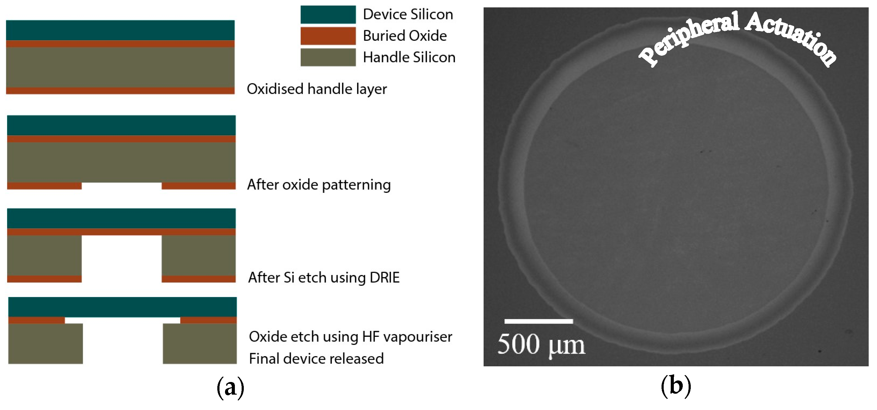
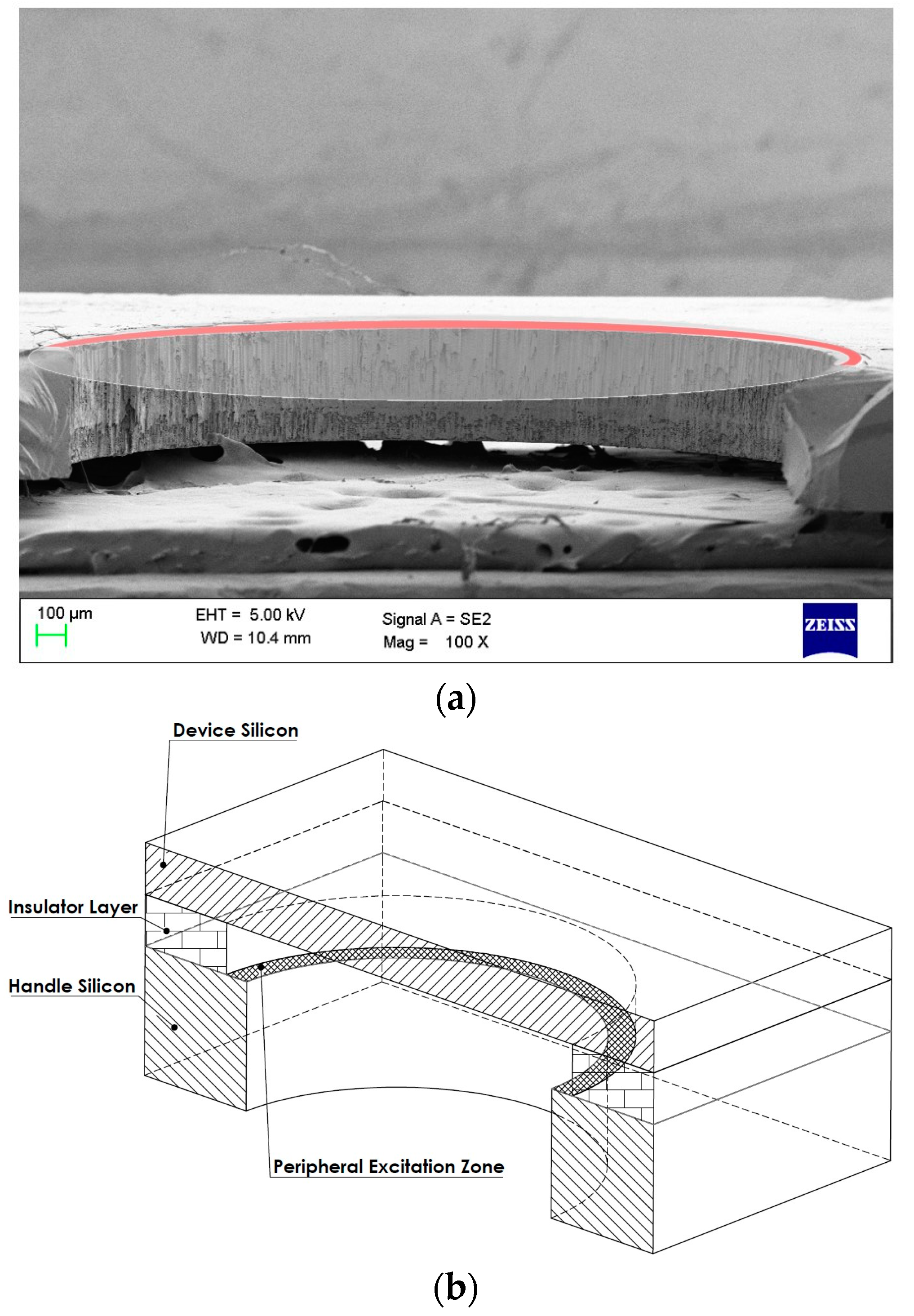
The main concern in designing MEMS speakers with electrostatic actuation is the need for small separation between the top and bottom electrodes for efficient driving. Field crickets actuate the sound producing structure in their forewings by applying impulse loading on the file teeth present at the boundary of the structure [2]. This is different as compared to the actuation used at the center in all the man-made speakers. So, we design the MEMS speaker to have electrostatic actuation only at the periphery of the radiating structure. Since the entire device is not suspended over a bottom substrate, the issues of pull-in [3] and squeeze film [4] do not affect its performance. We use a SOI wafer (buried oxide—500 nm; device layer—2 μm) and simple steps (Figure 1a) using inexpensive (photo printed) masks to fabricate the MEMS speakers. An optical image of the fabricated device is shown in Figure 1b. The electrostatic actuation takes place over the ring shaped peripheral region, where the top and bottom electrodes (Figure 2).
3. Experimental Results
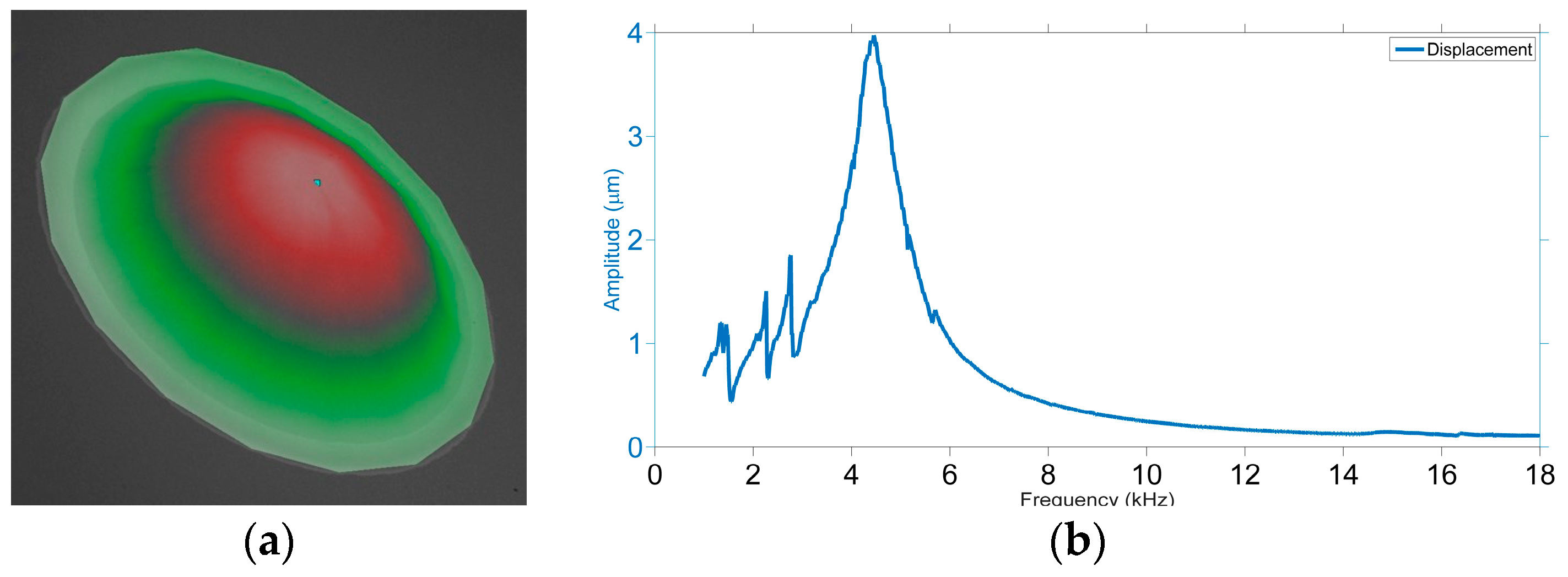
We measure the dynamic response of the structure using a Laser Doppler Vibrometer (MSA500, Polytec). The experimentally measured mode shape, shown in Figure 3a, clearly indicates that the device vibrates in its first mode. We observe that the vibration amplitudes are considerable even though the actuation is only at the outer periphery of the device (Figure 3b).
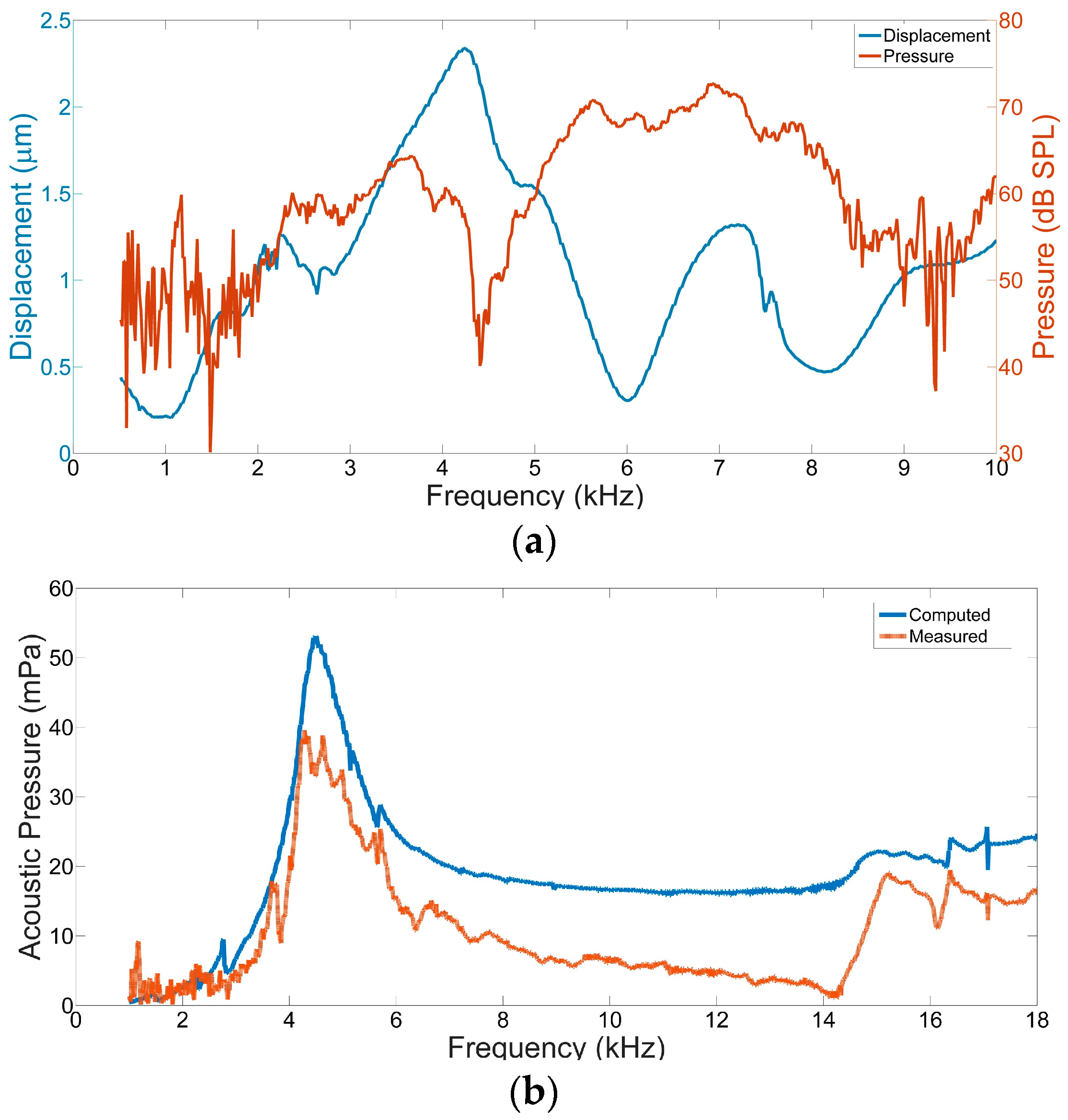
The radiated sound output (at 10 cm) is captured using a ½” microphone (Type 4190-L-001, B&K) as shown in Figure 4a. The theoretically computed acoustic pressure based on the amplitude of vibration also agrees well with the experimentally measured acoustic output as shown in Figure 4b. The marginal deviation from theoretically expected acoustic pressure output can be attributed to the assumption of the device to behave as a plane circular piston. In reality, the circular diaphragm is vibrating in its first, breathing mode (Figure 3a). We also see (Figure 4a) that a single MEMS speaker of 2.9 mm diameter and 0.5 mm overall thickness is able to radiate a maximum pressure of about 66 dB SPL at 10 cm while consuming an input power of just 4.8 mW.
4. Discussion and Conclusions
Learning from the above results we design an array of MEMS speakers to increase the output sound pressure level. An array of 25 of such MEMS speakers, which will have a size of 15 × 15 × 0.5 mm3, will produce a sound pressure of approximately 94 dB SPL at 10 cm while consuming an input power of about 120 mW. This puts the efficiency of the MEMS speaker array at 0.126% which is one order of magnitude higher than the dynamic speakers (from Knowles, IL, USA) shown in Table 1. We believe that there is a huge potential in developing these high efficiency MEMS speakers for various specific applications in consumer electronics and the music industry.
Acknowledgments
We thank the NNFC and MNCF teams at the Centre for Nano Science and Engineering, Indian Institute of Science, Bengaluru for the help and support during fabrication and characterization of the micro speaker. We also thank DST for funding the project.
Conflicts of Interest
The authors declare no conflict of interest.
References
- Lemarquand, G.; Ravaud, R.; Shahosseini, I.; Lemarquand, V.; Moulin, J.; Lefeuvre, E. MEMS electrodynamic loudspeakers for mobile phones. Appl. Acoust. 2012, 73, 379–385. [Google Scholar] [CrossRef]
- Godthi, V.; Pratap, R. Dynamics of Cricket Sound Production. J. Vib. Acoust. 2015, 137, 041019. [Google Scholar] [CrossRef]
- Elata, D.; Bamberger, H. On the dynamic pull-in of electrostatic actuators with multiple degrees of freedom and multiple voltage sources. JMEMS 2006, 15, 131–140. [Google Scholar] [CrossRef]
- Bao, M.; Yang, H. Squeeze film air damping in MEMS. Sens. Actuators A Phys. 2007, 136, 3–27. [Google Scholar] [CrossRef]
Figure 1.
The figure (a) shows the fabrication steps to obtain the MEMS speaker using only a SOI wafer, and (b) shows the optical image of the MEMS speaker fabricated using a single SOI wafer.
Figure 1.
The figure (a) shows the fabrication steps to obtain the MEMS speaker using only a SOI wafer, and (b) shows the optical image of the MEMS speaker fabricated using a single SOI wafer.

Figure 2.
The figure (a) shows an SEM image of the device cross-section where the suspended diaphragm is removed for clear view of the structure, showing position of peripheral actuation (red) highlighted, along with schematic of the suspended diaphragm, figure (b) shows a schematic of the device cross-section highlighting the peripheSral region for electrostatic actuation.

Figure 3.
The figure (a) shows the experimental mode shape of the structure as observed using Polytec Laser Doppler Vibrometer, MSA-500, (b) shows plot of the displacement response (center point on the diaphragm) from a single MEMS device actuated at diaphragm’s natural frequency.
Figure 3.
The figure (a) shows the experimental mode shape of the structure as observed using Polytec Laser Doppler Vibrometer, MSA-500, (b) shows plot of the displacement response (center point on the diaphragm) from a single MEMS device actuated at diaphragm’s natural frequency.

Figure 4.
Plot (a) shows the measured output sound pressure in decibels with the corresponding displacement of the diaphragm, plot (b) shows the measured radiated pressure (mPa) from a single MEMS device and the pressure computed based on the displacement response.
Figure 4.
Plot (a) shows the measured output sound pressure in decibels with the corresponding displacement of the diaphragm, plot (b) shows the measured radiated pressure (mPa) from a single MEMS device and the pressure computed based on the displacement response.


Table 1.
Comparison of size and efficiency between various dynamic speakers from Knowles, USA and our biomimetic MEMS speaker array.
Table 1.
Comparison of size and efficiency between various dynamic speakers from Knowles, USA and our biomimetic MEMS speaker array.
| Model | Size (mm3) | Input Power (mW) | Pressure Output at 10 cm (dB SPL) | Efficiency (%) |
|---|---|---|---|---|
| Donau | 11 × 15 × 3.5 | 350 | 89 dB | 0.014 |
| Mean | 10 × 14 × 2.9 | 250 | 84 dB | 0.006 |
| Dumbo | 13 × 18 × 4.5 | 700 | 92 dB | 0.012 |
| Sambo | 13 × 18 × 4.5 | 700 | 96 dB | 0.031 |
| Fox | 09 × 16 × 3.0 | 500 | 86 dB | 0.006 |
| Nautilus | 11 × 15 × 4.0 | 350 | 89 dB | 0.014 |
| MEMS Speaker Array (25) | 15 × 15 × 0.5 | 120 | 94 dB | 0.126 |
Publisher’s Note: MDPI stays neutral with regard to jurisdictional claims in published maps and institutional affiliations. |
© 2017 by the authors. Licensee MDPI, Basel, Switzerland. This article is an open access article distributed under the terms and conditions of the Creative Commons Attribution (CC BY) license (https://creativecommons.org/licenses/by/4.0/).
Share and Cite
MDPI and ACS Style
Garud, M.; Godthi, V.; Reddy, J.; Dangi, A.; Pratap, R. Cricket Inspired High Efficiency MEMS Speakers. Proceedings 2017, 1, 345. https://doi.org/10.3390/proceedings1040345
AMA Style
Garud M, Godthi V, Reddy J, Dangi A, Pratap R. Cricket Inspired High Efficiency MEMS Speakers. Proceedings. 2017; 1(4):345. https://doi.org/10.3390/proceedings1040345
Chicago/Turabian StyleGarud, Meera, Vamsy Godthi, Jayaprakash Reddy, Ajay Dangi, and Rudra Pratap. 2017. "Cricket Inspired High Efficiency MEMS Speakers" Proceedings 1, no. 4: 345. https://doi.org/10.3390/proceedings1040345