Aerosol/Ink Jet Printing Technology for High-Temperature MEMS Sensors †


1
Kurchatov Complex of Physical and Chemical Technologies, National Research Center Kurchatov Institute, Moscow 123182, Russia
2
Sensor Laboratory, ITMO University, Saint-Petersburg, Russia
3
LLC RIIIT, Ostec Group, Moscow, Russia
4
National Research Nuclear University “MEPhI”, Moscow, Russia
*
Author to whom correspondence should be addressed.
†
Presented at the Eurosensors 2017 Conference, Paris, France, 3–6 September 2017.
Proceedings 2017, 1(4), 617; https://doi.org/10.3390/proceedings1040617
Published: 18 August 2017
(This article belongs to the Proceedings of Proceedings of Eurosensors 2017, Paris, France, 3–6 September 2017)
Abstract
:In this work we present the results on the application of additive technology that is aerosol and ink jet technique for the fabrication of high-temperature metal oxide gas sensors. The application of thin (12 μm) alumina membrane, aerosol jet printing of Pt microheater (line width 40–60 μm), printed sensing layer made of nanocristalline tin dioxide based material, laser cutting of the membrane enabled the fabrication of full-printed cantilever-shaped high-temperature sensor with optimal power consumption (~80 mW at 450 °C) applicable in wireless instruments for the detection of combustible and toxic gases including methane.
1. Motivation
We present an overview of the results obtained with the application of aerosol and ink jet technologies for the fabrication of high temperature (up to 400–500 °C) gas, flow, and temperature sensors. The application of jet printing in combination with ceramic MEMS structures based on thin alumina, LTCC and yttria stabilized zirconia (YSZ) membranes enables the fabrication of cost efficient devices with thermal characteristics compatible with those of silicon based MEMS.
The metallic inks with Pt, Au, and Ag nanoparticles can be printed over these ceramic membranes giving stable Pt microheater working up to 500 °C. The nanoparticle sensing layers based on metal oxide semiconductors are printed using the same technique giving efficient semiconductor and thermocatalytic gas sensors. The main field of application of such sensors, in addition to normal working condition devices, is high temperature application in car industry, heavy accident and combustion processes monitoring.
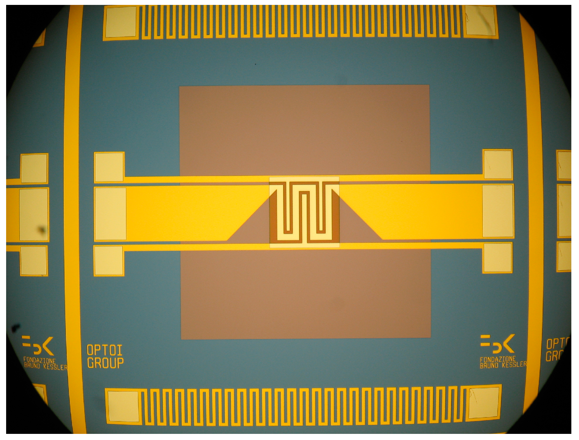
The development of ceramic MEMS technology with jet printed functional elements of the sensor are very important now, because recent technology of silicon MEMS for the fabrication of low power consuming semiconductor gas sensor (Fondazione Bruno Kessler (FBK, Trento, Italy, Figure 1), AMS (Premstaetten, Austria), Figaro (Osaka, Japan)) or polyimide substrate [1] have evident disadvantages due to restricted annealing and working temperature (about 300–350 °C for both microhotplate, and 450 °C for FBK’s unit). Another problem is the application of expensive and sophisticated equipment in silicon technology and the use of sputtering processes in the fabrication of noble metal (Pt, Au) layers deposition. The third problem is low flexibility of traditional microelectronic manufacturing process leading to difficulties in the fabrication of different modifications of sensors using the same process. These problems make the silicon technology hardly usable in sensor production.
2. Results and Discussion
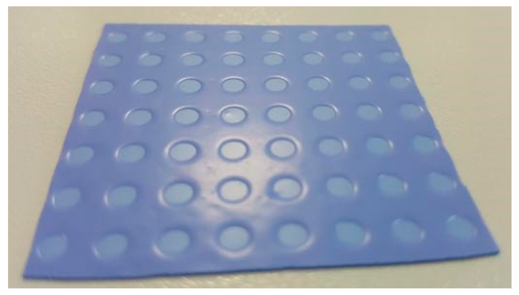
We developed the technology of thin ceramic membranes usable in highly-efficient ceramic MEMS devices operating at temperature up to 450–500 °C. The material of membrane is Al2O3, LTCC, or YSZ (10–20 μm thick). Membrane is stretched on rigid frame. The substrate with thin membranes is adopted for the group technology, because the substrate contains many sensor elements (Figure 2).
The heater is fabricated using ink or aerosol jet printing with Pt nanoparticle. Typical particle size of these inks is of 3–8 nm. The ink is made by suspension of metal nanoparticles in solvent with viscosity of ~10 cP (typically, ethylene glycol). After sintering, this print gives a microheater stable at temperature up to 500 °C.
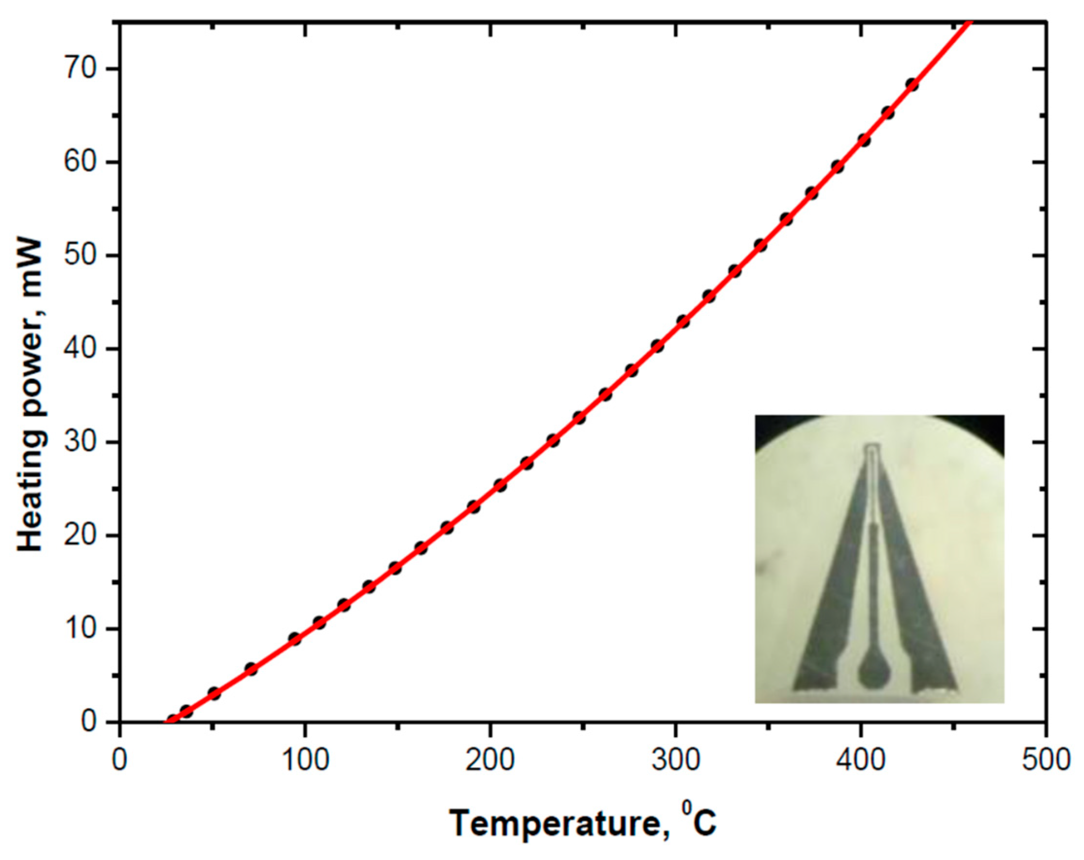
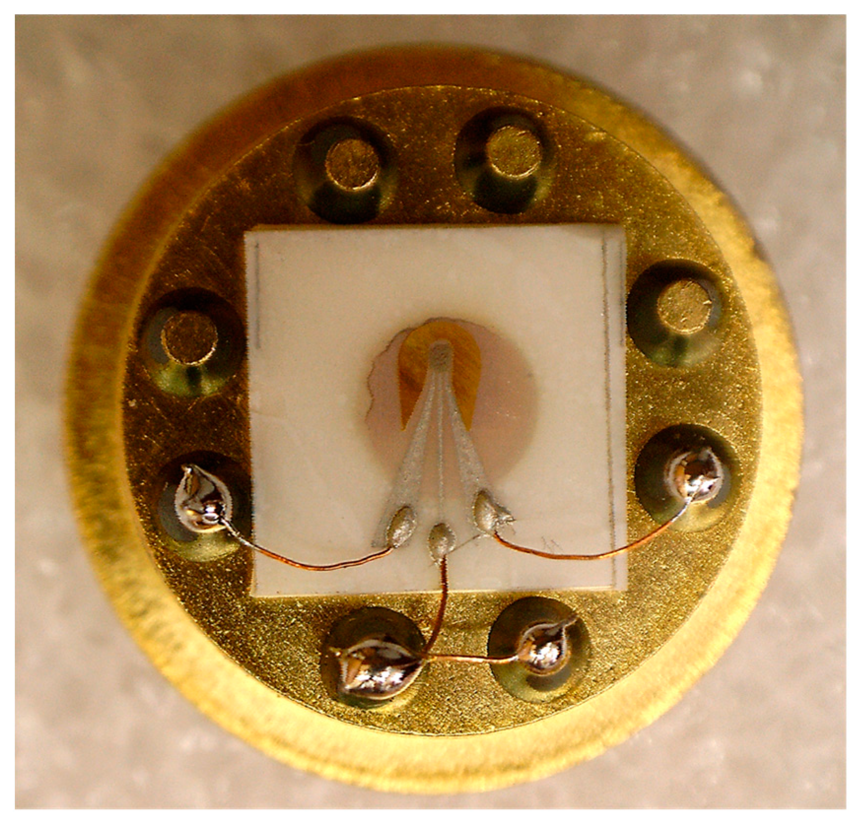
Power consumption of the sensor made by ink jet printing is of ~70 mW at 450 °C (Figure 3), this is comparable with Si-based MEMS. The power consumption of the microheater with aerosol jet printed microheater is a little higher, ~80 mW, due to higher heat conductivity of more dense Pt print. Cantilever shaped microhotpalate improves the stability of the microheater at temperature cycling. It is made by cutting by fibre optic laser (20 W). The view of the full-printed microsensor with deposited sensing layer made of Pd-doped tin dioxide (specific surface area of about 100 m2/g) is presented in Figure 4. The chip size is of 6 × 6 mm, membrane diameter is of 3 mm. Hot area of the microheater is of about 250 × 250 μm.
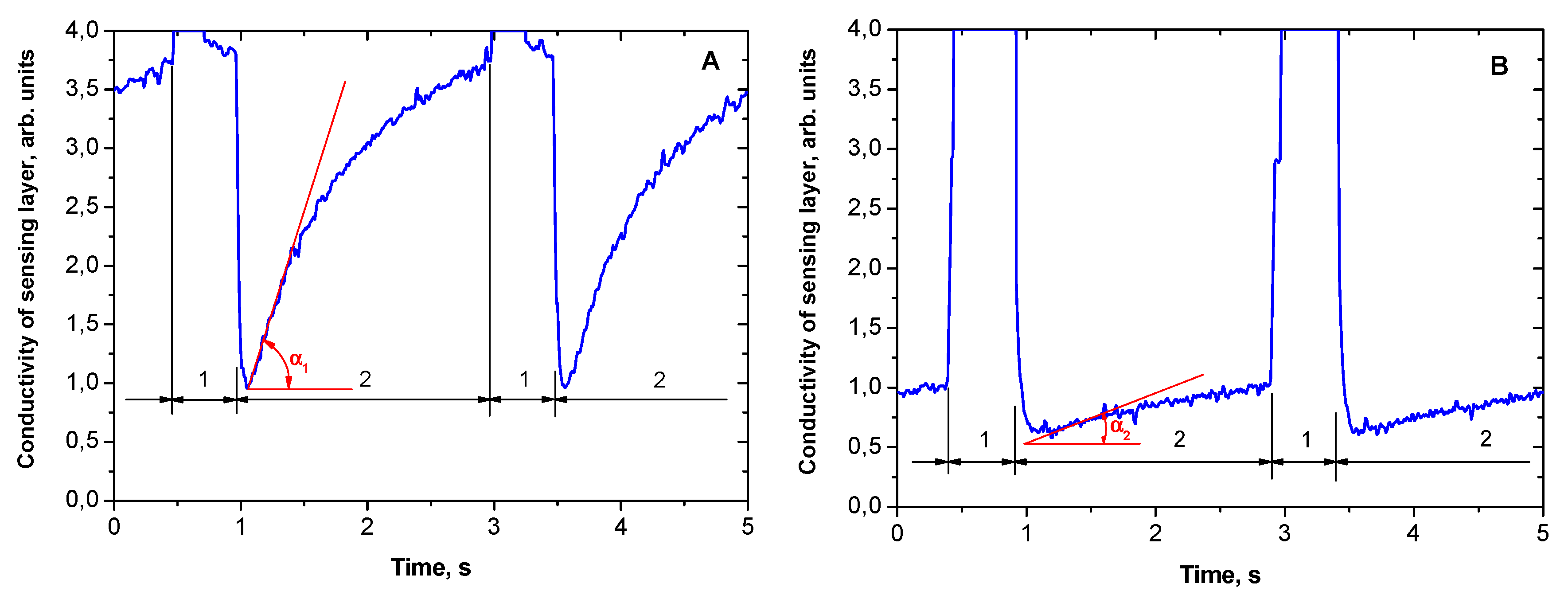
The temperature cycling enables an improvement of sensor selectivity (Figure 5A,B, response to CO and H2, respectively [3]) and a decrease in power consumption down to <1 mW.
The deposition of metal oxide nanoparticle semiconductor or catalytic sensing layer of chemoresistive of thermochemical gas sensors is possible using the same printing technique. The sensors demonstrate usual response to gases, it is equal, for example, to factor of 7–10 at methane concentration of 1 vol. %. Detection limit of selective measurement of CO and H2 is of about 1 ppm. In the example presented in Figure 5 and Figure 6 the sensing layer containing tin dioxide doped with Pd is first heated to 450 °C for 0.5 s. At this temperature palladium is oxidized and forms palladium oxide. At low temperature part of the measurement cycle (110 °C, 2.5 s) palladium oxide is consumed to the oxidation of CO molecules. This temperature is sufficient for fast oxidation of carbon monoxide, but not sufficient for the oxidation of hydrogen with palladium oxide (Figure 5B).
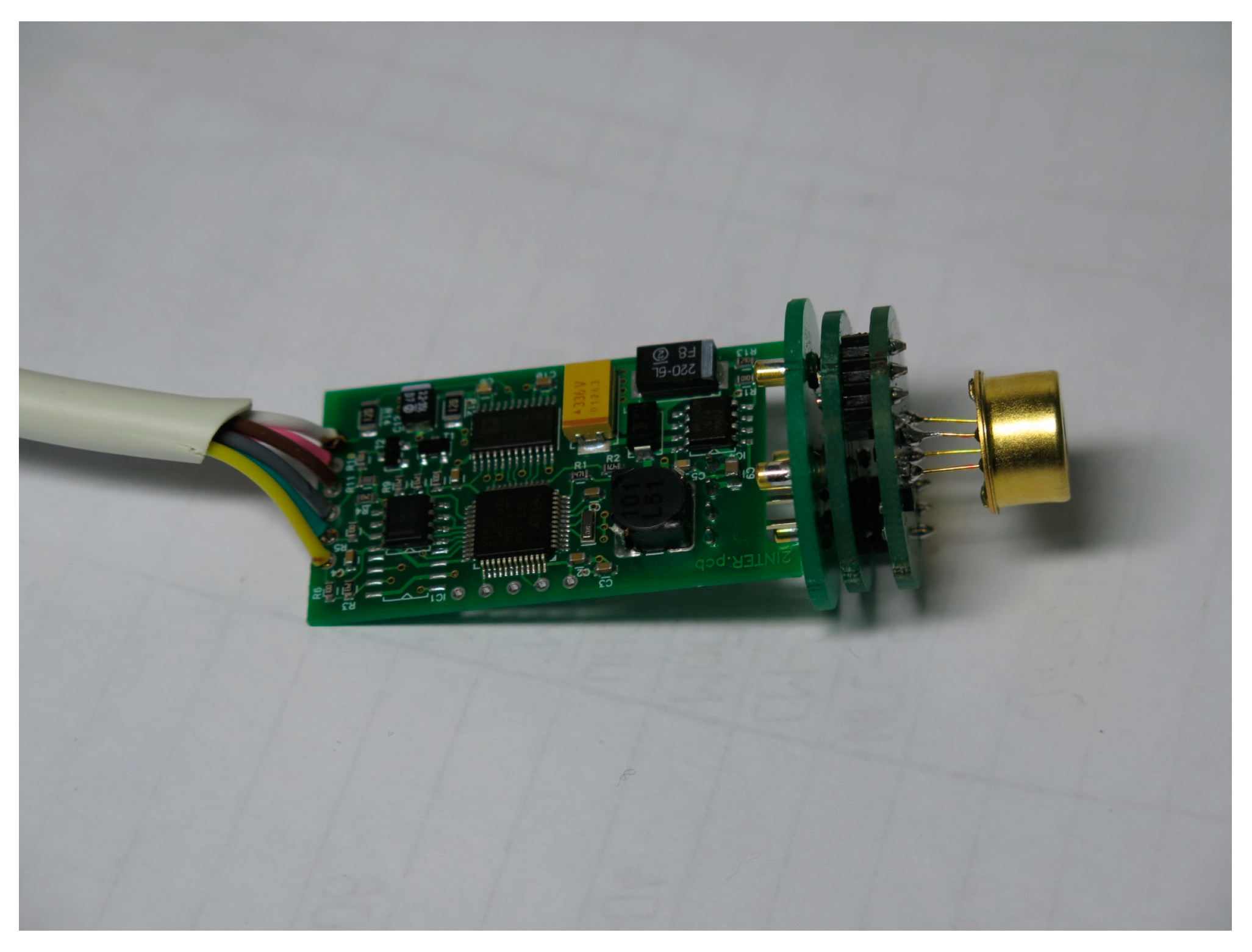
Smart module fabricated for controlling ceramic MEMS sensors are developed to assure plug-and-play operation mode of sensor units. The smart sensor unit (Figure 6) is, in fact, a complete measuring instrument with microprocessor realizing pre-calibration of the sensor, The main advantage of such unit is the possibility of hot replacement of the unit with calibrated in laboratory ones.
Conflicts of Interest
The authors declare no conflict of interest.
References
- Rieu, M.; Camara, M.; Tournier, G.; Viricelle, J.P.; Pijolat, C.; de Rooij, N.F.; Briand, D. Fully inkjet printed SnO2 gas sensor on plastic substrate. Sens. Actuators B 2016, 236, 1091–1097. [Google Scholar] [CrossRef]
- Vasiliev, A.A.; Pisliakov, A.V.; Sokolov, A.V.; Polovko, O.V.; Samotaev, N.N.; Kujawski, W.; Rozicka, A.; Guarnieri, V.; Lorenzelli, L. Gas Sensor System for the Determination of Methane in Water. Procedia Eng. 2014, 87, 1445–1448. [Google Scholar] [CrossRef]
- Vasiliev, A.A.; Pisliakov, A.V.; Sokolov, A.V.; Samotaev, N.N.; Soloviev, S.A.; Oblov, K.; Guarnieri, V.; Lorenzelli, L.; Brunelli, J.; Maglione, A.; et al. Non-silicon MEMS platforms for gas sensors. Sens. Actuators B 2016, 224, 700–713. [Google Scholar] [CrossRef]
Figure 1.
Pt microheater on SiO2/Si3N4 membrane. Heater size is of ~300 × 300 μm, maximum sensor working temperature is of 450 °C (FBK/NRC KI [2]).
Figure 1.
Pt microheater on SiO2/Si3N4 membrane. Heater size is of ~300 × 300 μm, maximum sensor working temperature is of 450 °C (FBK/NRC KI [2]).

Figure 2.
20 μm thick and 3 mm in diameter LTTC membranes stretched on rigid 100 μm LTCC frame prepared for Pt printing using aerosol jet technology.
Figure 2.
20 μm thick and 3 mm in diameter LTTC membranes stretched on rigid 100 μm LTCC frame prepared for Pt printing using aerosol jet technology.

Figure 3.
Power consumption of microheater on 12 μm alumina ceramic film as a function of microhotplate temperature. The microheater view is given on close-up photo.
Figure 3.
Power consumption of microheater on 12 μm alumina ceramic film as a function of microhotplate temperature. The microheater view is given on close-up photo.

Figure 4.
Full printed high-temperature gas sensor made of 12 μm thick alumina. Power consumption is of ~80 mW (continuous heating up to 450 °C) and about 1 mW (pulsing heating with duty cycle of 1%). Cantilever-type sensor is adopted for autonomous and wireless gas analyzers.
Figure 4.
Full printed high-temperature gas sensor made of 12 μm thick alumina. Power consumption is of ~80 mW (continuous heating up to 450 °C) and about 1 mW (pulsing heating with duty cycle of 1%). Cantilever-type sensor is adopted for autonomous and wireless gas analyzers.

Figure 5.
(A) Response of MEMS based sensor to 3 ppm of CO. Sensing material is SnO2 (10 nm particles) + 3 wt.% of Pd. Measurement cycle is 450 °C (0.5 s) + 110 °C (2.5 s). The slope of the curve (tan α1) is proportional to CO concentration. (B) Response of MEMS based sensor to 3 ppm of H2. Sensing material and measurement cycle are the same as those in (A). The slope of the curve (tan α2) is proportional to H2 concentration. Selectivity factor for the CO/H2 is equal to about 10, that is the ratio of slopes at the same concentrations of CO and H2 (tan α1/tan α2) ≈ 10.

Figure 6.
Smart sensor unit with gas sensor in TO-8 packaging. The round board is a smart unit with UART interface enabling temperature control of the sensor and providing all information about concentration of gas, type of sensor, enabling compensation of ambient humidity, etc. Diameter of this board is of 25 mm.

Publisher’s Note: MDPI stays neutral with regard to jurisdictional claims in published maps and institutional affiliations. |
© 2017 by the authors. Licensee MDPI, Basel, Switzerland. This article is an open access article distributed under the terms and conditions of the Creative Commons Attribution (CC BY) license (https://creativecommons.org/licenses/by/4.0/).
Share and Cite
MDPI and ACS Style
Vasiliev, A.A.; Nisan, A.V.; Samotaev, N.N. Aerosol/Ink Jet Printing Technology for High-Temperature MEMS Sensors. Proceedings 2017, 1, 617. https://doi.org/10.3390/proceedings1040617
AMA Style
Vasiliev AA, Nisan AV, Samotaev NN. Aerosol/Ink Jet Printing Technology for High-Temperature MEMS Sensors. Proceedings. 2017; 1(4):617. https://doi.org/10.3390/proceedings1040617
Chicago/Turabian StyleVasiliev, Alexey A., Anton V. Nisan, and Nikolay N. Samotaev. 2017. "Aerosol/Ink Jet Printing Technology for High-Temperature MEMS Sensors" Proceedings 1, no. 4: 617. https://doi.org/10.3390/proceedings1040617