Capillary Microvalve Actuation Using Thermal Expansion of Trapped Air Bubble †

1
Life Science Technologies Department, IMEC, Kapeldreef 75, 3001 Heverlee, Belgium
2
Department of Physics and Astronomy, KU Leuven, Celestijnenlaan 200d, 3001 Heverlee, Belgium
*
Author to whom correspondence should be addressed.
†
Presented at the Eurosensors 2018 Conference, Graz, Austria, 9–12 September 2018.
Proceedings 2018, 2(13), 1031; https://doi.org/10.3390/proceedings2131031
Published: 16 November 2018
(This article belongs to the Proceedings of EUROSENSORS 2018)
Abstract
:In this study, we demonstrate a compact actuation mechanism of a silicon capillary stop microvalve, based on electrothermal expansion of a trapped air bubble in a chamber. The bubble is heated using an integrated aluminum microheater deposited on the silicon substrate above the air chamber. The heater occupies an area of 320 µm × 300 µm and has a resistance of 40 Ohms. By applying a 500 ms voltage pulse of 3 V amplitude we could generate a pressure sufficient to breach the capillary barrier pressure of valve, which is around 1000 Pa.
1. Introduction
The success of a truly miniaturized Lab-on-a-Chip system depends largely on the effectiveness of fluidic control. For this, on-chip microvalves play an important role [1]. An ingenious way to control capillary-driven fluid transport in a microfluidic chip is by taking advantage of specially designed microstructures called capillary stop valves. If the cross section of a microchannel expands abruptly, the liquid-vapor interface gets pinned to the sharp edge of the valve and moves no further. An excess pressure (referred to as a capillary pressure barrier) must be supplied to the liquid to resume flow. Methods proposed to overcome this barrier include centrifugal force [2], and the use of a second capillary-driven fluid stream [3].
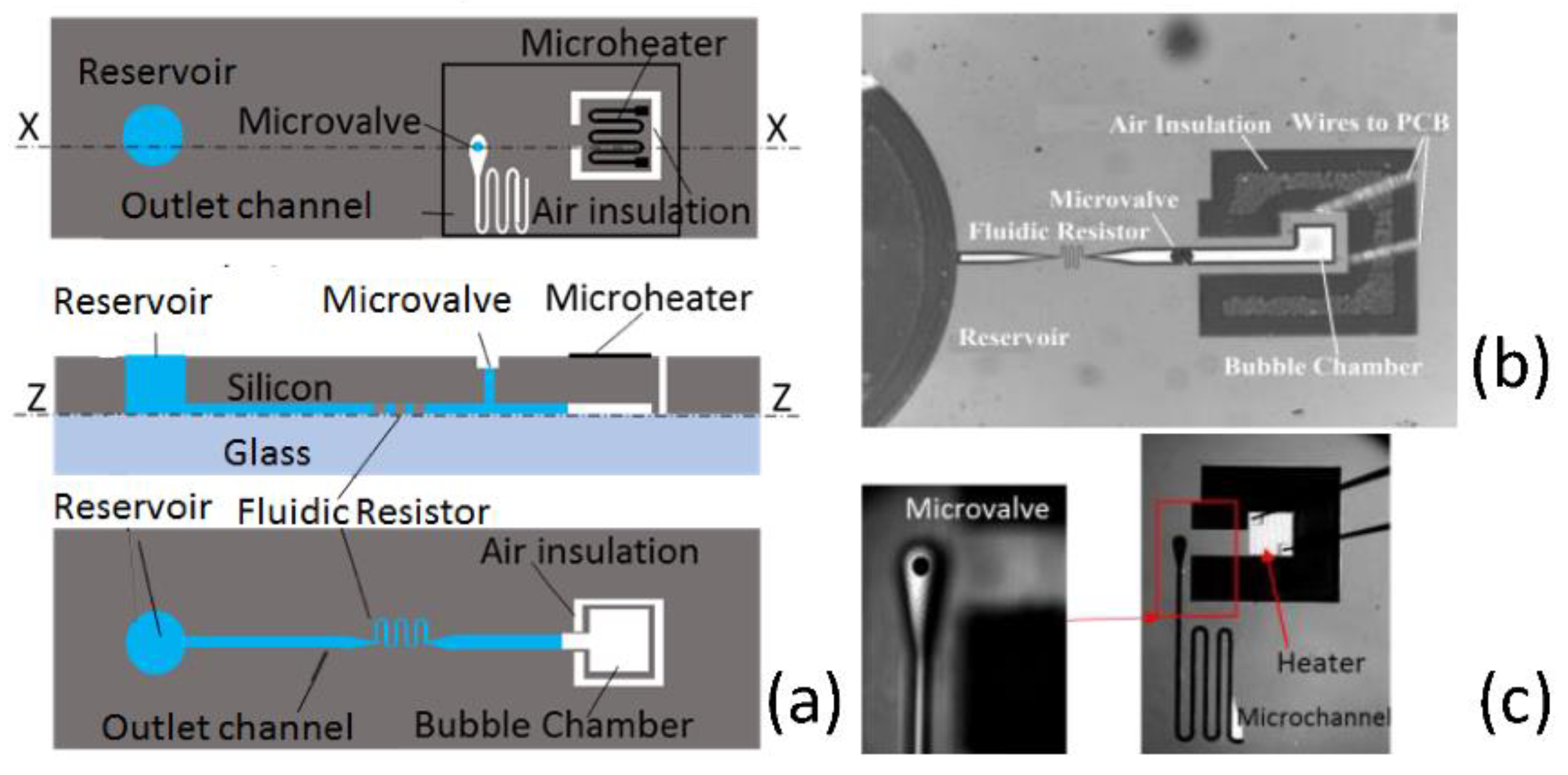
Thermal actuation via gas expansion has also been proposed [4] but never demonstrated in the literature. Here, we present a thermal actuation system which is compact, without mechanical elements, has a fast response and can be integrated with previously described micro-PCR chips [5]. The schematic of the device is shown in Figure 1a. Liquid advances by capillary force from the reservoir in an inlet channel, passing through a fluidic resistor and reaches the microvalve region where it is split in two parts. One rises along the wall of a vertical channel and is pinned at its exit. The other advances towards the bubble chamber where, since there is no outlet, an air bubble is trapped. An integrated microheater is used to generate a short heat pulse. As the backflow towards the reservoir is limited by the presence of the fluidic resistor, a fast and effective pressure increase is obtained that overcomes the capillary pressure barrier. To confine heating to the air bubble region, thermal insulating trenches are implemented by removing silicon around the heater.
2. Materials and Methods
2.1. Fabrication
The fabrication is carried out on a 200 mm wafer and goes through three main steps: frontside etch, bonding and backside processing. The nominal etch depth is 30 µm for the inlet microfluidic channel, the fluidic resistor and the bubble chamber and 200 µm for all those structures that must be in contact with backside features (reservoir, thermal insulation trenches and microvalve vertical channel). These structures are then sealed by a borosilicate glass wafer (500 µm thick) using anodic bonding. Afterwards the silicon wafer is ground to a thickness of 400 µm. An electrically insulating layer of silicon oxide (200 nm thick) and an aluminum layer (300 nm thick) are deposited on the backside. Al is patterned to form a meandered microheater in correspondence of the bubble chamber. Thereafter, a backside etch to a depth of 200 µm is performed to define the inlet reservoir, the outlet channel and the thermal insulation trenches. Figure 1b shows a picture of the fabricated device taken from the glass side. Dimensions are as follows: the inlet channel is 140 µm wide and 30 µm deep; the sides of the rectangular bubble chamber are 300 µm and 320 µm and the depth is again 30 µm; the fluidic resistor consists of a 5 µm wide serpentine channel of a total length of around 1 mm. Due to the small width, the depth of the resistor is less than the nominal etch depth, namely about 20 µm. Figure 1c shows a picture of the fabricated device taken from the silicon side. The meandered microheater has a width of 15 µm and a length of around 5.6 mm, its electrical resistance is 40 Ω at room temperature. The reservoir has a diameter of 2 mm, the vertical stop valve a diameter of 120 µm and the exit channel a width of 40 µm.
2.2. Experimental Procedure
The chip is mounted on a PCB and the microheater is wire bonded to PCB contacts using 25 µm diameter aluminum wires. A programmable Keithley 2602 source meter provides a voltage pulse of 3 V for 0.5 s. The resistivity of the microheater is a function of temperature and this property is exploited to measure its temperature. The temperature coefficient of resistance, determined by a calibration process, is α = 0.00385 K−1. If the wires and the heater (which are made of the same material) would be at the same temperature, the heater temperature could be calculated from the relation R = R0 (1 + α(T − T0)), -where R0 and R are the total resistance of heater and wires, respectively at room temperature, T0, and at a temperature T. The magnitude of the error in temperature is given by ε = 2*Rw0(Tw – Th)/R0 where Rw0 is the wire resistance at T0, and Tw and Th are wire and heater temperatures respectively. As Rw0/R0 is about 2% we expect this error to be small. A more accurate estimation is given in the results section. During valve actuation the heater current is recorded as a function of time, the heater resistance is calculated, and the behavior of temperature versus time is obtained. To follow the behavior of the valve during operation, the camera of an inverted microscope captures bright field images of the bubble side, and a second camera takes the images of the microvalve side. The fluid used for testing is 40 mL DI water to which 10 µL of surfactant (Triton-X, Sigma Aldrich, St. Louis, MO, USA) been added to control the contact angle value. The surface tension and contact angle of the fluid have been measured using the sessile drop and pendent drop methods respectively.
2.3. Thermal Modelling
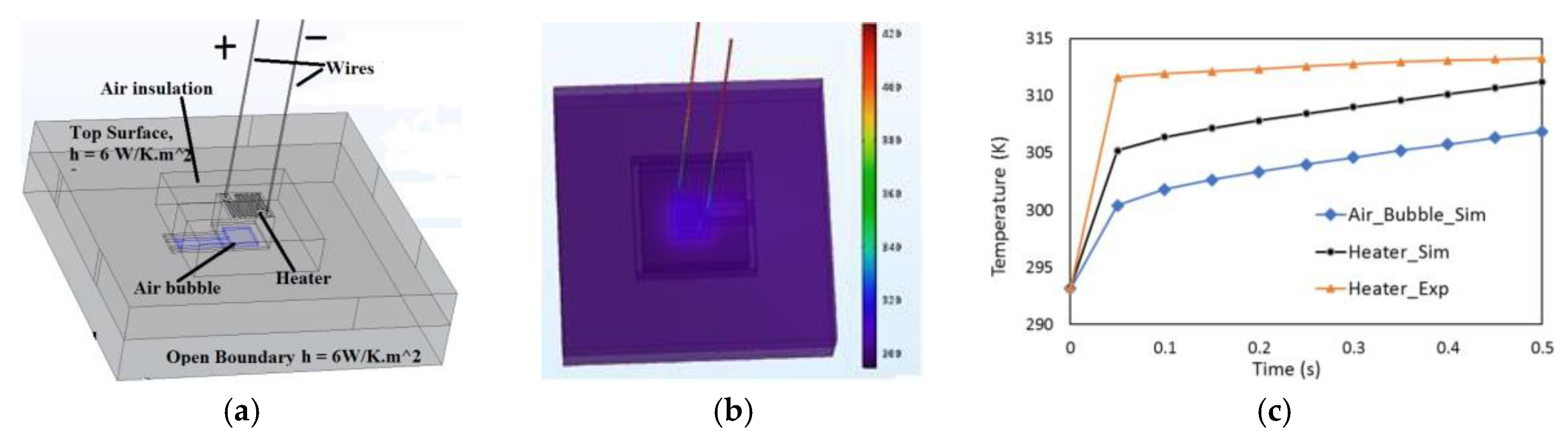
A 3D electro-thermal fully coupled finite element time dependent model using COMSOL MULTIPHYSICS 5.2a [6] has been setup in order to investigate the relationship between the heater and the air bubble temperatures. The domain is of 3.6 mm × 3.6 mm in area, surrounding the air insulation region around the trapped air bubble. In order to fully simulate the heating process, 25 μm dia. aluminum wires, each of length 7.5 mm, are connected to the contact pads, at each end of the heater. The voltage pulse is applied across the free ends of the wires. The top and bottom surfaces are given a convective heat transfer coefficient, h = 6 W/K·m2. The lateral surfaces are considered as open boundaries which allow heat to flow out of the domain with external constant ambient temperature of 293.15 K. Figure 2a depicts the boundary conditions of the domain.
3. Results
3.1. Thermal Characteristics
Figure 2b shows the temperature profile of the domain 0.35 s after the start of the pulse. The simulated temperature of the heater and of the air bubble are reported as a function of time in Figure 2c. The system reacts rapidly to the application of power and the temperature difference between the air bubble and the heater remains constant at 4 K after 0.1 s. Figure 2c also reports the experimental heater temperature, corrected for the bond wire resistance. The correction is about 1.5 K, evaluated using the simulated average temperatures of the wires. The temperature rise is faster in the experiment than in simulation but the final temperatures are in good agreement.
3.2. Valve Actuation
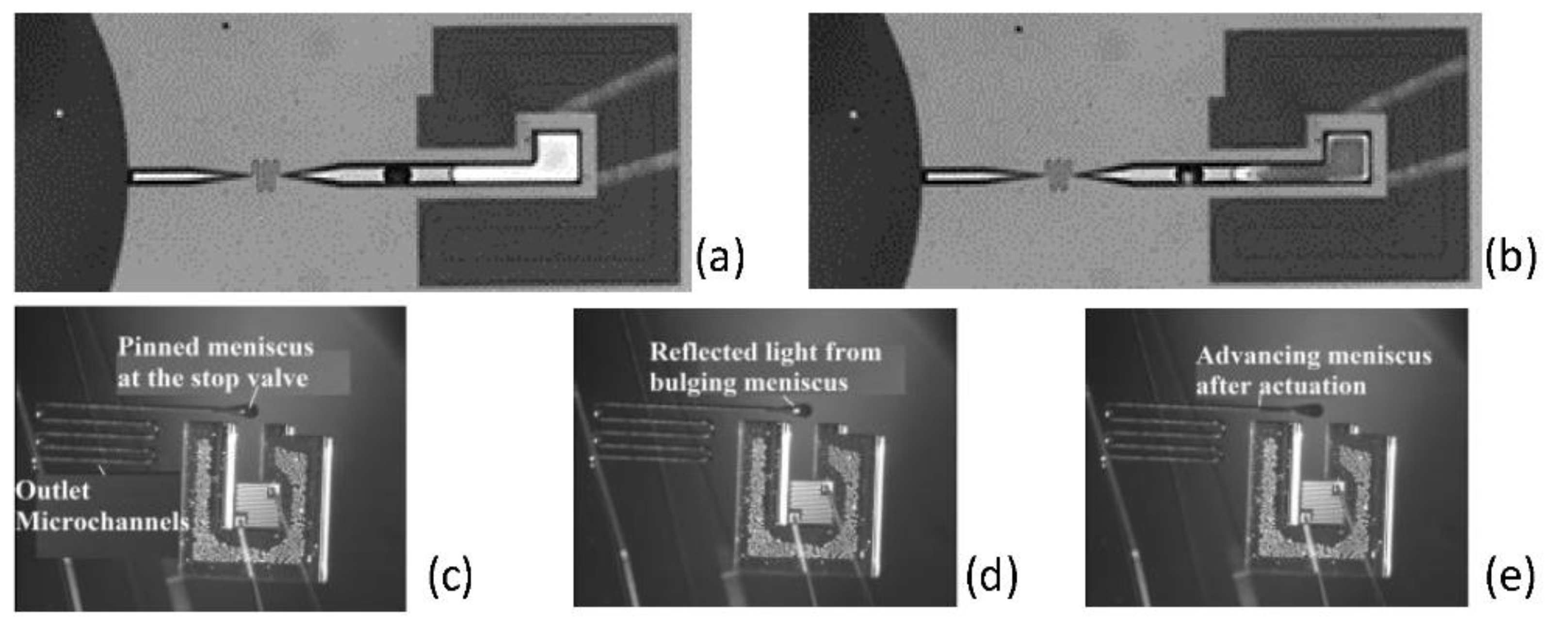
Figure 3 depicts the meniscus position after priming (a) and after actuation (b). The stroke volume is measured from image analysis and is 2.52 × 10⁻¹³ m3. Figure 3c–e show the backside of the valve, before, during and after actuation. During actuation, Figure 3d, a flash of light is captured in the image due to bulging meniscus. In Figure 3e, it can be clearly seen that the valve has been actuated as the fluid is filling the outlet channel. In the current experiment, the frontside and backside cameras are not synchronized, so it is impossible to determine volume, pressure and temperature at the moment of actuation. Despite this, we can still make some conclusions linking gas parameters and valve actuation.
Using the ideal gas equation, the following relationship can be easily deduced:
where ∆P, ∆V and ∆T are respectively the variation in pressure, volume and temperature from the initial state and the subscript 0 indicates initial values. The initial volume at room temperature, T0 = 293 K, determined from image analysis, is V0 = 4.94 × 10⁻¹² m3. The initial pressure, derived from inlet channel dimensions and from measured values of contact angle, 47°, and surface tension, γ = 40 mN/m, is estimated at 102.60 KPa.
ΔP/P0 = ΔT/T0 – ΔV/V0
To evaluate ∆P and ∆V, let’s consider a circular capillary stop valve with 90° expansion. Before actuation the meniscus is flat. It is assumed that the valve actuates once the angle between the meniscus and the surfaces of the sudden expansion reaches the contact angle. At actuation the volume of the spherical cap is ∆V = (1/3)πh2(3r/sin θ − h), where r is the radius of capillary valve, θ the contact angle and h = r(1/sin θ − cot θ) the meniscus height. We obtain ∆V = 1.49 × 10⁻¹³ m3. As for the actuation pressure the expression ∆P = 2γsin(θ)/r, gives a value of 975 Pa. From the values calculated above we can derive the corresponding ∆T from (1). It is found to be around 12.1 K; i.e., the air bubble temperature is T = 305.1 K corresponding to a heater temperature of 309.1 K. This is the minimum temperature needed to actuate the valve and Figure 2c clearly show that it has been reached.
4. Conclusions
A capillary stop valve which can be opened by electrothermal means has been designed and fabricated in silicon technology. The actuation mechanism occupies a small area, of the order of 0.1 mm2, and an energy of only 0.1 J is sufficient for its actuation (0.25 W for 0.5 s). The realized valve serves as an alternative to the classical capillary stop valve whose actuation is controlled by a second fluid; the advantage of electrical actuation is the increased flexibility and accuracy in controlling the sequence of fluidic operations.
Acknowledgments
We acknowledge Federico Buja for silicon fabrication, and Frank Gijbels and Alejandra Jauregui Uribe for assistance with the experimental setup.
Conflicts of Interest
The authors declare no conflict of interest. The founding sponsors had no role in the design of the study; in the collection, analyses, or interpretation of data; in the writing of the manuscript, and in the decision to publish the results.
References
- Oh, K.W.; Ahn, C.H. A review of microvalves. J. Micromech. Microeng. 2006, 16, R13–R39. [Google Scholar] [CrossRef]
- Ducree, J.; Haeberle, S.; Lutz, S.; Pausch, S.; Stetten, F.; Zengerle, R. The centrifugal microfluidic Bio-Disk platform. J. Micromech. Microeng. 2007, 17, S103–S115. [Google Scholar] [CrossRef]
- Zimmermann, M.; Hunziker, P.; Delamarche, E. Valves for autonomous capillary systems. Microfluid. Nanofluid. 2008, 5, 395–402. [Google Scholar] [CrossRef]
- Bohm, S. Triggerable Passive Valve for Use in Controlling the Flow of Fluid. U.S. Patent 7,059,352 B2, 13 June 2006. [Google Scholar]
- Barman, U.; Wiederkehr, R.S.; Fiorini, P.; Lagae, L.; Jones, B. A comprehensive methodology for design and development of an integrated microheater for on-chip DNA amplification. J. Micromech. Microeng. 2018, 28, 085014. [Google Scholar] [CrossRef]
- Available online: www.comsol.com (accessed on 1 July 2018).
Figure 1.
(a) Schematic of the thermally actuated capillary valve. Top: Top view, Middle: cross section. (X-X), Bottom: cross section (Z-Z). (b) Micrograph of the device as seen through the glass side. (c). Micrograph of the device as seen from the silicon side.
Figure 1.
(a) Schematic of the thermally actuated capillary valve. Top: Top view, Middle: cross section. (X-X), Bottom: cross section (Z-Z). (b) Micrograph of the device as seen through the glass side. (c). Micrograph of the device as seen from the silicon side.

Figure 2.
(a) Computational domain with boundary conditions, (b) temperature contours of the chip at t = 0.35 s and (c) temperature variation of bubble, and heater (both simulation and experimental).
Figure 2.
(a) Computational domain with boundary conditions, (b) temperature contours of the chip at t = 0.35 s and (c) temperature variation of bubble, and heater (both simulation and experimental).

Figure 3.
Glass side view (a) before and (b) after thermal actuation. The displacement of the meniscus is clearly visible. Silicon side view (c) before actuation, (d) during actuation with bulging meniscus and (e) after actuation.
Figure 3.
Glass side view (a) before and (b) after thermal actuation. The displacement of the meniscus is clearly visible. Silicon side view (c) before actuation, (d) during actuation with bulging meniscus and (e) after actuation.

Publisher’s Note: MDPI stays neutral with regard to jurisdictional claims in published maps and institutional affiliations. |
© 2018 by the authors. Licensee MDPI, Basel, Switzerland. This article is an open access article distributed under the terms and conditions of the Creative Commons Attribution (CC BY) license (https://creativecommons.org/licenses/by/4.0/).
Share and Cite
MDPI and ACS Style
Barman, U.; Fiorini, P.; Lagae, L.; Jones, B. Capillary Microvalve Actuation Using Thermal Expansion of Trapped Air Bubble. Proceedings 2018, 2, 1031. https://doi.org/10.3390/proceedings2131031
AMA Style
Barman U, Fiorini P, Lagae L, Jones B. Capillary Microvalve Actuation Using Thermal Expansion of Trapped Air Bubble. Proceedings. 2018; 2(13):1031. https://doi.org/10.3390/proceedings2131031
Chicago/Turabian StyleBarman, Ujjal, Paolo Fiorini, Liesbet Lagae, and Benjamin Jones. 2018. "Capillary Microvalve Actuation Using Thermal Expansion of Trapped Air Bubble" Proceedings 2, no. 13: 1031. https://doi.org/10.3390/proceedings2131031