Ballistic Ground Penetrating Radar Equipment for Blast-Exposed Security Applications
by
 , , , and
Federico Lombardi
1,* ,
,
Maurizio Lualdi
1,
Francesco Picetti
2,
Paolo Bestagini
2,
Gerardus Janszen
3 and
Luca Angelo Di Landro
3 1
Department of Civil and Environmental Engineering, Politecnico di Milano, Piazza Leonardo da Vinci 32, 20133 Milan, Italy
2
Department of Electronics, Information and Bioengineering, Politecnico di Milano, Piazza Leonardo da Vinci 32, 20133 Milan, Italy
3
Department of Aerospace Science and Technology, Politecnico di Milano, Via La Masa 34, 20156 Milano, Italy
*
Author to whom correspondence should be addressed.
Remote Sens. 2020, 12(4), 717; https://doi.org/10.3390/rs12040717
Submission received: 30 January 2020
/
Revised: 14 February 2020
/
Accepted: 20 February 2020
/
Published: 21 February 2020
(This article belongs to the Special Issue Advanced Ground Penetrating Radar Theory and Applications)
Abstract
:Among all the forensic applications in which it has become an important exploration tool, ground penetrating radar (GPR) methodology is being increasingly adopted for buried landmine localisation, a framework in which it is expected to improve the operations efficiency, given the high resolution imaging capability and the possibility of detecting both metallic and non-metallic landmines. In this context, this study presents landmine detection equipment based on multi-polarisation: a ground coupled GPR platform, which ensures suitable penetration/resolution performance without affecting the safety of surveys, thanks to the inclusion of a flexible ballistic shielding for supporting eventual blasts. The experimental results have shown that not only can the blanket absorb blast-induced flying fragments impacts, but that it also allows for the acquisition of data with the accuracy required to generate a correct 3D reconstruction of the subsurface. The produced GPR volume is then processed through an automated learning scheme based on a Convolutional Neural Network (CNN) capable of detecting buried objects with a high degree of accuracy.
1. Introduction
Ground Penetrating Radar (GPR) technology, a non-destructive technique based on the propagation and reflection of electromagnetic waves [1,2], has been successfully adopted as a subsurface prospection tool to assist forensic investigation in a broad range of security applications, from buried explosive threats to human remains detection, as well as locating and tracking people in disaster areas [3,4]. It is therefore evident, the wide variety of possible targets and scenarios that GPR equipment developed for security tasks has to deal with, which implies a degree of flexibility hardly achievable with other geophysical alternatives [5,6,7,8].
Humanitarian demining is a fundamental component of post-conflict land release operations, a time-consuming and dangerous process necessary to mitigate the long-term social and economic effects caused by the laying and non-removal of not only landmines, but also by improvised and abandoned explosives. Despite technological progresses, the most common tool for detecting landmines is still the metal detector [9], and the process is still primarily conducted manually, with an operator carefully checking the ground [10,11]. Considerable efforts have been made to develop a solution to the problem of landmine detection, and GPR is one of several technologies that has been extensively researched with respect to mine clearance operations [12,13].
GPR has been proposed as an alternative to classical electromagnetic induction techniques for landmine detection due to a number of advantages, the principal one being the ability to detect landmines with little or no metal content, as long as there is a difference in the electromagnetic contrast between the ground and the target [14]. In addition, advanced imaging algorithms and data post-processing has allowed not only localisation of the target but also to extract valuable features that can pave the way for target recognition and identification [15,16,17,18,19,20]. However, standalone GPR platforms for antipersonnel landmine detection are less common than their metal detector counterparts [21], a situation possibly related to the fact that GPR signal interpretation remains a complex task, and that the mentioned benefits are often balanced by its susceptibility to clutter [22,23], i.e., reflections coming from events that are unrelated to the target scattering characteristics but which occur in the same time window and have similar characteristics to the target wavelet. Being a deterministic signal, stable in time, might reduce the detection threshold of the system, resulting in an unacceptably high False Alarm Rate (FAR) [24].
As a consequence, GPR equipment have been recently been included in demining platforms as a complementary unit with a metal detector to achieve considerable improvements in detection performance, clearance rate, and a significant reduction in false alarms [25,26]. In terms of the technology readiness level, the most advanced systems are the US Army AN/PSS-14 (formerly Handheld Standoff Mine Detection System, HSTAMIDS) hand-held detector [27] developed by CyTerra (now L-3 Communications, US), the Anglo-German Vallon-Cobham VMR3 Minehound (formerly MINETECT) humanitarian detector [28], the ALIS (Advanced Land Mine Imaging System), developed by Tohoku University (Japan), and the CEIA (Italy) [29].
Applications of GPR in forensic investigations are mostly focused on searching for human remains and missing or trapped people, as well as the detection of clandestine graves and buried shelters [30,31]. The principal reasons for its successful deployment are the enhanced operations efficiency, mainly due to the possibility of rapidly highlighting suspected areas to then be thoroughly searched, and the preservation of the scene thanks to its non-destructive nature. In the framework of natural disasters or structural collapses, GPR technology has shown its effectiveness in locating victims in a very short time.
All of the described applications share the potential risk of being exposed to possible blasts and explosions, being intentional or accidental. A landmine might be accidentally triggered during a survey or can be self-activated due to weathering and ageing effects, the interiors of collapsed buildings might include flammable debris, and underground structures might have been transformed into ammunitions shelter or storage. This means that, at the same time, both the operator and the equipment should be protected. While the first aspect is of the utmost importance, the protection of the acquisition platform emerges as a relevant feature when evaluated under the perspective of system durability and hence affordability. These are critical factors to be taken into account when developing technology for humanitarian assistance.
Finally, recalling the possible scenarios and objectives of a GPR survey, there is a growing need for the automation of the processing chain, making it as much scenario-agnostic as possible. To achieve this self-sufficiency, learning-based methodologies have been increasingly explored and their performances have often shown to outperform classical methods in many fields of application. In particular, data-driven methodologies that learn features characterising buried targets directly from the GPR images, rather than imposing any preliminary model, are increasingly gaining relevance [32,33,34,35].
Developed within a research project denominated “PoliMIne: Humanitarian Demining GPR System”, the presented work covers two major challenges in the application of GPR for security operations: (1) the integration of ballistics and electronics to assemble an affordable, portable, and blast-resistant GPR-based system and (2) the development of robust GPR signal processing techniques for buried anomaly detection and identification.
In particular, the developed solution employs a high frequency, dual polarised GPR system, accurately and precisely scanning the surface over a dedicated ballistic pad. The armoured pad not only provides blast protection and shielding but also contributes to distribute the equipment weight, and eventually the operator weight, over a larger area, reducing the risk of localised high pressure. On the whole, the pressure transmitted by the antenna to the soil through the blanket is expected to be far below the triggering threshold of an antipersonnel landmine, which can be considered one of the most sensitive activation mechanisms.
The data are then processed through a learning technique, known as Convolutional Neural Networks (CNNs), to detect the presence of buried objects not coherent with the surrounding soil texture [36,37,38]. Compared to other supervised learning alternatives, CNNs, a deep learning technique particularly suited for computer vision and image classification tasks, determine the classification features in an automated way directly from the raw data, i.e., without the need for extensive manual data labelling.
The structure of the remainder of this paper is as follows. Section 2 describes the experimental test site developed for the purpose of this study, while in Section 3 and Section 4, the employed GPR platforms and the ballistic blanket are respectively characterised and tested. The achieved detection performance is presented and commented upon in Section 5. Finally, conclusions are discussed in Section 6.
2. Material and Methods
In order to validate the proposed system architecture, a dedicated test site was developed, consisting of a number of different targets which comprise inert landmines, surrogate models, and battlefield debris. In particular:
- Three inert antipersonnel landmine models (PFM-1, SB-33 and VS-50), deactivated and filled with an explosive simulant commonly used for training purposes.
- Ten antipersonnel surrogate models (provided by Fenix Insight Ltd), moulded in epoxy resin and with the representative metallic components.
- Five clutter and Unexploded Ordnance (UXO) simulants.
The targets are described in Table 1 and pictured in Figure 1, while further details can be found at http://ordata.info/.
The targets were buried with their top at a depth of 15 cm below the ground surface and with an interdistance of 30 cm between each target to avoid mutual interference. Despite rarely being deeper than 10 cm on initial placement, the specified depth was adopted for several reasons. First of all, buried landmines, especially when in place for a long time, are subjected to several environmental factors that might cause an increase of their depth, such as land modifications and shifting [39,40], thus becoming deeply buried. Then, the selected depth was made accordingly to the clearance requirement for humanitarian demining defined by the United Nations Mine Action Service (UNMAS), which states that “For buried mines and UXO this depth should not normally be less than 13 cms below the original surface level and is based on the effective depth of the majority of metal detectors” [41,42]. Finally, the choice was made as a way to measure the maximum performance for target detection, to verify whether the system would be able to reach a depth below which mines cannot reasonably be present.
The utilised test bay was an indoor facility, filled with a sharp sand material exhibiting a gritty texture and a very low clay content. The measured velocity was approximately 14 cm/ns, with a consequential dielectric value of 4.5.
The GPR data were acquired using an IDS Aladdin (IDS Georadar srl) radar, an impulse system with a central frequency and a bandwidth of 2 GHz. The device carries two orthogonal bow–tie antennas spaced 6 cm geometrically located so that the reflection centres correspond for both couples and coincide with the geometrical center of the unit (Figure 2). Such geometry allows two orthogonal scans to be acquired at once.
The sensor head, which is essentially a passive component weighting approximately 2 kg and with a size of 12 cm by 12 cm, is connected to a central unit responsible for the generation, transmission, and reception of the signal.
The acquisition and system parameters are provided in Table 2.
Except for a time calibration, performed through an autocorrelation function, and frequency filtering to remove out of band noise, no additional processing steps have been applied on the data.
Due to logistical constraints, several 1 m by 1.8 m areas were acquired, resulting in 114 GPR profiles for each sector, with an average time spent on each acquisition of around 20 min.
To obtain unaliased 3D subsurface images, inline data sampling was controlled by an odometric wheel directly attached to the sensor head, while uniform profile spacing and constant antenna orientation were achieved through the use of the PSG (Pad System for Georadar, [43,44], as shown in Figure 2). The evaluated survey procedure, which differs from the most widespread approaches to GPR surveys, was mainly driven by (1) the need for a properly sampled data volume, so that there is no missing information on the subsurface, and (2) the need for collecting data which can yield as many features of the target as possible, hence the choice of a system working directly on the surface, rather than suspended over it. The practical importance of these assumptions will be demonstrated in the following section.
The main modification of the original solution has been focused on the need for a material capable of withstanding a blast and shielding the above area from eventual fragments, and at the same time maintaining a reduced weight, so that also investigations over rugged surfaces might be allowed.
3. Ground Penetrating Radar System Analysis
GPR operational effectiveness mostly depends on the following parameters: (1) adequate penetration with respect to the expected target depth, (2) sufficiently wide bandwidth with respect to the desired resolution, (3) efficient coupling of the emitted waveform into the ground, and (4) sufficient scattered signal from the buried objects. Therefore, when determining the suitability of the equipment, the soil characteristics, target properties, and the system fundamental parameters have to be carefully considered.
In this context, the following Section will justify the choice of the GPR equipment through the evaluation of its fundamental operational principles.
3.1. Frequency
There are three main parameters which influence the frequency selection:
- Required resolution.
- Clutter limitations.
- Required penetration.
There is a fundamental trade-off between the spatial resolution, signal attenuation, and achievable depth. To increase the penetration performance and limit signal losses, the operating frequency can be lowered. However, this reduces the available bandwidth, which is directly proportional to the maximum achievable resolution. On the other hand, increasing the frequency could lead to richer and improved results; however, the faced absorption might be excessively high, even for near surface and shallow applications. The attenuation of a material is, to a first order, linearly related in dB/m to frequency, and, in the second instance, to the square root of the permittivity of the material, with the additional aspect that such path loss is not always a linear function of depth, therefore the detection capability can significantly vary. Depending on the soil characteristics, namely its relative dielectric constant and conductivity, the ground can be considered to be acting as a low pass filter, effectively placing a window across the antenna aperture. The severity of this tapering can be mainly attributed to the moisture and the clay content of the material, so that wetter materials, despite providing a better electromagnetic contrast, are virtually opaque.
Given the wide variability of soil characteristics, it is clear that accurately predicting the propagation behaviour and the target scattering pattern to establish the optimal frequency might be arduous, and this trade-off has been solved by choosing a central frequency, and accordingly the bandwidth, of 2 GHz, consistently with the common choice of demining equipment. To validate this choice, and in particular whether a higher frequency equipment might reach a sufficient depth for the considered application, we chose to carry out a survey burying the two inert antipersonnel landmines (VS-50 and SB-33 model) in an organic soil scenario (exhibiting a relative dielectric of 14 and a velocity of 8 cm/ns), maintaining the same acquisition parameters and target geometry previously described. This choice of an unfavourable terrain for electromagnetic investigations has been made considering also that the material included in the test bay, though indicative of several mine affected regions of the world, represents a favourable propagation environment, especially in terms of soil texture homogeneity.
In particular, the employed system has been compared to a similar GPR platform featuring a central frequency and a bandwidth of 3 GHz, and the obtained radar profiles are shown in Figure 3.
The two targets are hardly detectable in the 3 GHz equipment profile (Figure 3d), underlining the possibility that, even for shallow targets, attenuation might be more than enough to prevent higher frequency systems from penetrating down to the target.
At the same time, the improvements in the resolution performance brought by a wider bandwidth, which essentially implies a shorter temporal duration of the emitted waveform, are clearly visible, particularly when analysing the shallower layer of the radar profile. Such layers appear highly blurred in the 2 GHz profile (Figure 3c), and the very first centimetres are almost completely masked by the ground reflection. This last factor suggests also that narrowing the bandwidth for preserving penetration rather than resolution might negatively affect the capability of correctly imaging, or even detecting, superficial targets. As a figure of merit, a theoretical estimation of the minimum soil thickness allowing the ground reflection to be separated from the one generated by a very shallow target can be made considering the maximum vertical resolution of the system. In particular, the 2 GHz equipment exhibits a resolution value with respect to the minimum, central, and maximum wavelength, of respectively 2 cm, 1 cm, and 0.7 cm, while for the 3 GHz system, these are reduced to 1.3 cm, 0.7 cm, and 0.4 cm. Strictly theoretically, this means that even a landmine buried in the very first centimetres can be properly located.
Regarding instead the sandy test site, which can be considered as the upper bound regarding soil velocity and hence achievable resolution, the lower frequency GPR device is characterised by a minimum landmine–surface separation of 3.5–1.75 cm and 1.2 cm, always considering the three wavelength regions. It can be therefore stated that the choice of the frequency well meets the trade-off between penetration performance and resolution.
Finally, in the case of a target buried just below the surface or even laid on the surface, its depth cannot be estimated, due to a lack of vertical resolution. However, it can still be detected given a sufficient contrast of electromagnetic properties (thanks to the ground coupled configuration) and considering the differences in the scattering properties between the ground surface and the landmine (diffraction hyperbola tails).
3.2. Antenna Elevation
As previously discussed, the antenna height above the ground is a critical factor, affecting both the design of the GPR platform and the quality of the collected data. It is clear that a stand-off radar system might represent a reasonable choice when surveying a hazardous area, but the impact of elevating the antennas on the reflected signal strength must be evaluated [45,46].
Figure 4 describes the penetration loss experienced by elevating the GPR sensor above the ground surface. Layers of styrofoam sheets, with a thickness of 5 cm, have been progressively inserted between the platform and the ground surface to simulate an increased system height. The material was chosen due to its low reflection properties to minimise its impact on the measurements. The considered target was the inert VS-50 antipersonnel landmine.
The results show that the target response reduces as the height of the antenna is increased, with the most significant losses occurring in the first steps, i.e., just detaching the antenna from the ground. In particular, it can be seen that the return from the target when the antennas are approximately 10 cm above the surface is almost totally lost, so that its detection from the analysis of these data would be challenging. To highlight the consequential impact of such losses on the spectral content of the received signal, and hence on its effective bandwidth, the spectrum of the recorded signal for each of the previous set-ups are shown in Figure 5.
The following considerations can be pointed out:
- Ground contact: The spectrum properly covers the entire frequency interval.
- Ground proximity (5 cm): While a slightly maximum amplitude increase can be noticed, the peak is shifted towards lower frequencies and the overall spectrum width is reduced.
- Stand-off configuration (10 cm): Both the width and the amplitude of the recorded spectrum are significantly reduced.
This indicates that employing a GPR system that is not in contact with the ground surface will experience increased energy losses, possibly precluding the detection in challenging soil conditions or deeper targets, and will suffer from a degraded resolution performance, thus hindering the classification and recognition tasks. The results obtained in the case of a limited antenna elevation (the red line of Figure 5) are a consequence of the fact that the system can still be considered to be operating in proximal conditions, and hence with a limited impact on the system performance. However, despite acceptable, the contraction of the width of the spectrum is not negligible, as it reduces down to almost 1.5 GHz. Consequently, the nearer to the ground the source is, the stronger the reflected signal will be.
Finally, the presented results have been acquired over an almost flat surface conditions; however, it is clear that when the surface topography variations may not be neglected, image degradation exhibited by a stand-off GPR system might be amplified [47].
3.3. Polarisation
Polarimetric information contained in the waves backscattered from a given target is highly related to its geometrical structure and orientation as well as to its physical properties and it affects how the radar system sees the object in the scenario. This implies that the visibility of a subsurface scatterer can be enhanced or reduced by taking advantage of its expected polarimetric response, and that the use of multiple polarisation can provide key additional information for target classification. The power of a wave scattered from an isotropic target is independent of the transmitter polarisation, while, for a linear target, the polarisation of the scattered field is independent of the transmitting polarisation. For a general target, instead, both the power and polarisation of the reflected wave vary with the transmitter polarisation [48,49,50].
In the context of this research, a landmine can be considered approximately geometrically regular, as shown in Figure 6, which compares the target radar cross section (RCS) for an antipersonnel landmine and a mortar shell, with varying incident polarisation.
The landmine signature shows approximately regular behaviour throughout the polarisation domain, in agreement with what is expected from a geometrically regular object, with the exception of slight variations, possibly due to the internal structure [51]. On the contrary, the mortar shell response exhibits a visible polarimetric dependent pattern, with a relevant magnitude span. In strict terms, this suggest that a single polarisation might be sufficient for landmine detection, as a change in the relative target geometry would not significantly impact the target scattering strength. However, such an approach might achieve a reduced detection performance in the case of a polarisation mismatch, or in the case of depolarising soil characteristics [52]. Another consideration, supporting the choice of dual polarisation equipment, is the possibility of stacking the acquired data, which theoretically results either in a signal to noise (SNR) improvement, for spheroidal objects like mines, or detection performance improvement, in the case of directional targets.
3.4. Data Acquisition
The possibility of developing automated GPR processing schemes is highly dependent on the level of information and the amount of features yielded by the GPR results. While typically analysed in the 2D domain, the use of 3D imaging techniques produces more realistic images of the subsurface, allowing for a more accurate location and for a 3D reconstruction not only of the buried targets, but also of the surrounding environment. The price to pay is a very high accuracy during acquisition, particularly in data density and regularity, to prevent possible artefacts resulting from the interpolation between the data samples [53]. Given the framework of application, the principal sources logistical obstacles, ground topography or poorly conducted surveys can be considered as the main sources of acquisition errors.
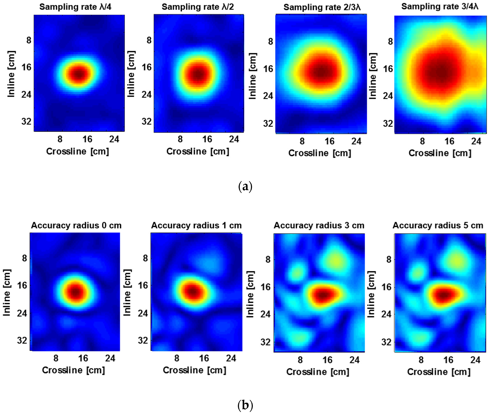
To highlight this aspect, Figure 7 describes the reconstruction results of a progressively wider spatial sampling, leading to a reduced horizontal resolution and spatial aliasing, as well as of a progressively degraded spatial accuracy in trace positioning. While the first aspect is defined as a function of the central wavelength, with the value of λ/4 representing the Nyquist criterion for spatial sampling, the corruption of the positioning accuracy can be defined as the distance with respect to the nominal position of the sample. Details on the approach and related data processing are given in [54].
The main consideration arising from the results is that a moderate violation of the spatial sampling requirements (Figure 7a) and a circumscribed deviation from the planned acquisition grid (Figure 7b) can be accepted, as both allow for a proper target detection and reconstruction. However, in the case of severe inaccuracy during data acquisition, there is a visible risk of either wrongly reconstructing the shape of the target or even not detecting the target. In addition, it must be considered that, in the provided example, both surface topography and soil heterogeneities are negligible. While the latter aspect is not easily predictable, the impact of uneven surfaces is minimised by the ground coupled configuration.
4. Ballistic Blanket Development
Considering the requirement of ground contact in order to reach reliable recordings, a shielding blanket placed on the ground, which is able to protect the personnel and the operating radar instrument in case of accidental blasts during the demining operations, was deemed necessary. Flexible, multilayer blankets were devised and assembled, similar to explosion containment blankets and ballistic protections employed in different situations [55,56,57].
In consideration of the expected service in the field, a lightweight, flexible, easy to handle blanket was designed with the objective of achieving a high protective efficiency from debris. In this view, a modular solution encompassing up to three multilayer blankets stacked one over the other (but even more could be assembled together) was devised, in order to have easy handling and, at the same time, achieve suitable conformability to ground morphologies and an adequate capability of adapting its weight and protection efficiency to the expected danger. Moreover, it is expected that a blanket with limited thickness and weight should provide only a negligible interference with the detection capacity of the radar system.
Aramid fabric was selected for the assembling of the shielding blankets, in consideration that such material is commonly employed as ballistic and blast protections in military and anti-terroristic uses, thanks to its remarkable mechanical strength and impact energy absorption characteristics [58]. Different configurations, including different numbers of fabric layers and variable fibre orientations, were impacted with steel balls in lab tests, with the aim to select adequate solutions in terms of protection efficiency to weight performance. A sample of blanket configurations were also checked with firearm bullets in a shooting range to test the perforation resistance.
It is to be noted that ballistics tests can provide valuable comparative and qualitative indications in relation to the specific use. While in testing activities, the projectile material, geometry, dimensions, and speed can be specifically selected; in actual situations, the nature, shape, weight, and energy of the projected debris are remarkably variable, while also dependent on the actual mine type and depth, as well as the soil characteristics. All these conditions may remarkably affect the actual debris containment efficiency of the protection systems.
4.1. Blanket Material
Aramid Style 101 Water-Repellent Ballistic Fabric, provided by SAATI SpA, Italy, was employed in all tests and for the manufacture of multilayer blankets. It is a plain-weave style made of Kevlar® 29, 3300 dtex, 460 g/m2 areal weight, 0.63 mm approximate thickness and 6.7 threads/cm, both in th warp and weft direction. The tensile behaviour of the fabric was characterized by static tests, performed following the ASTM 2261 standard, using a MTS Uniaxial Servo-hydraulic system. An extensometer was employed to measure the elongation of the material.
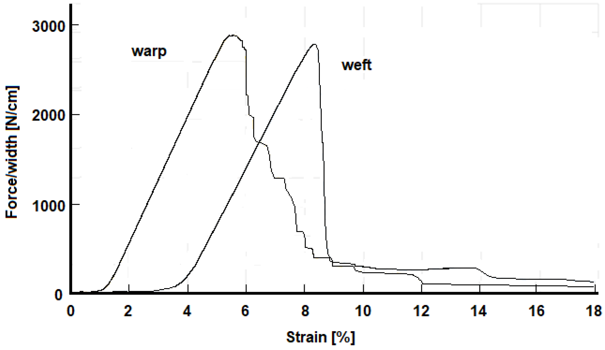
The specimens were obtained from the fabric by cutting rectangular strips 200 mm in length and 50 mm in width, both in the 0° (warp) and 90° (weft) direction. Although the tensile curves were sensibly similar, a limited difference in the maximum load and elongation was detected in the two testing directions, possibly due to the different thread tensioning during fabric manufacture. In Figure 8, an example of the load (referred to a unit fabric width) vs. strain curves is reported for specimens tested in the warp and weft direction.
Four distinct regions can be recognized in the fabric stretching process [59]. The first region (the crimp region) is characterized by low load values, due to the straightening of the yarns in the load direction; in the second region (the linear pre-peak region) the load linearly increases, reaching the tensile strength. After the peak, the fibres start to break, and the load radically decreases, partially in a linear way (the linear post-peak region) and partially in a non-linear way (the non-linear post peak region).
The resulting strength and stiffness data are summarised in Table 3.
4.2. Ballistics Tests
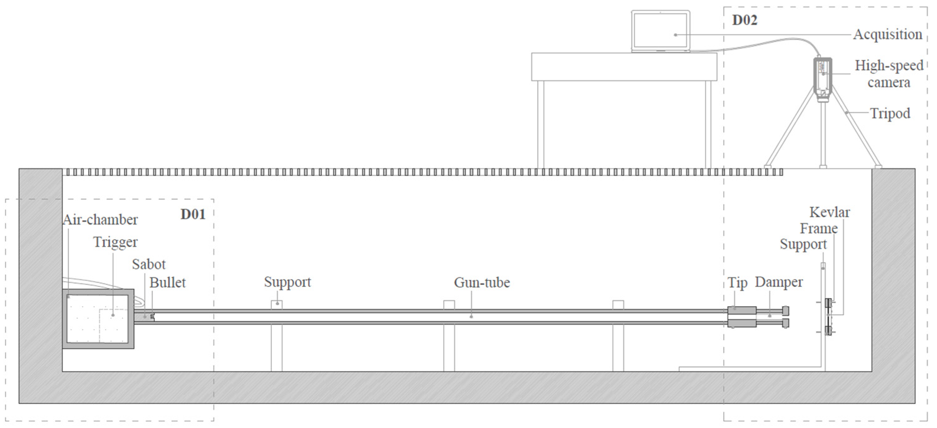
Ballistics tests were performed at the LaST laboratory of the Aerospace Science and Technology Department of Politecnico di Milano. The projectiles used were spherical steel balls with a diameter of 14 mm. These were accelerated up to 200 m/s with a compressed air device, comprising a pressurized air tank connected to a 7 m long tube, with a 40 mm inner diameter. A thin aluminium membrane separated the air reservoir from the accelerating tube, in which a cylindrical sabot carrying the projectile could be launched after breaking of the membrane by a trigger. At the end of the tube, a damper was placed to stop the sabot ride. A schematic of the test equipment is shown in Figure 9.
A high velocity Phantom v5.1 camera was used to measure the projectile’s speed before and after the impact with the target. In certain cases, the maximum allowable projectile speed could not be reached due to possible flow instabilities during the sabot acceleration; however, the actual projectile speed was recorded by the camera.
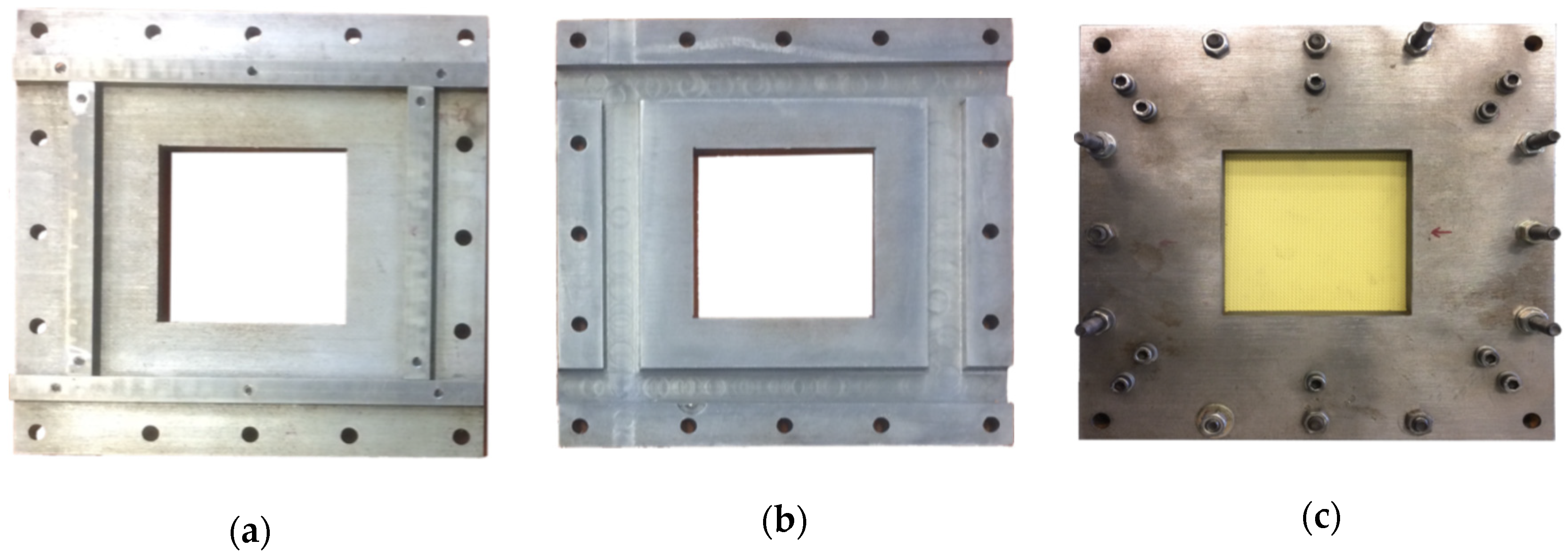
After various trials, a frame to support the specimens was designed and employed (see Figure 10), which was able to clamp the multilayer system up to eight fabric plies, while avoiding slippage in the clamping areas. The fabric free area is 100 × 100 mm.
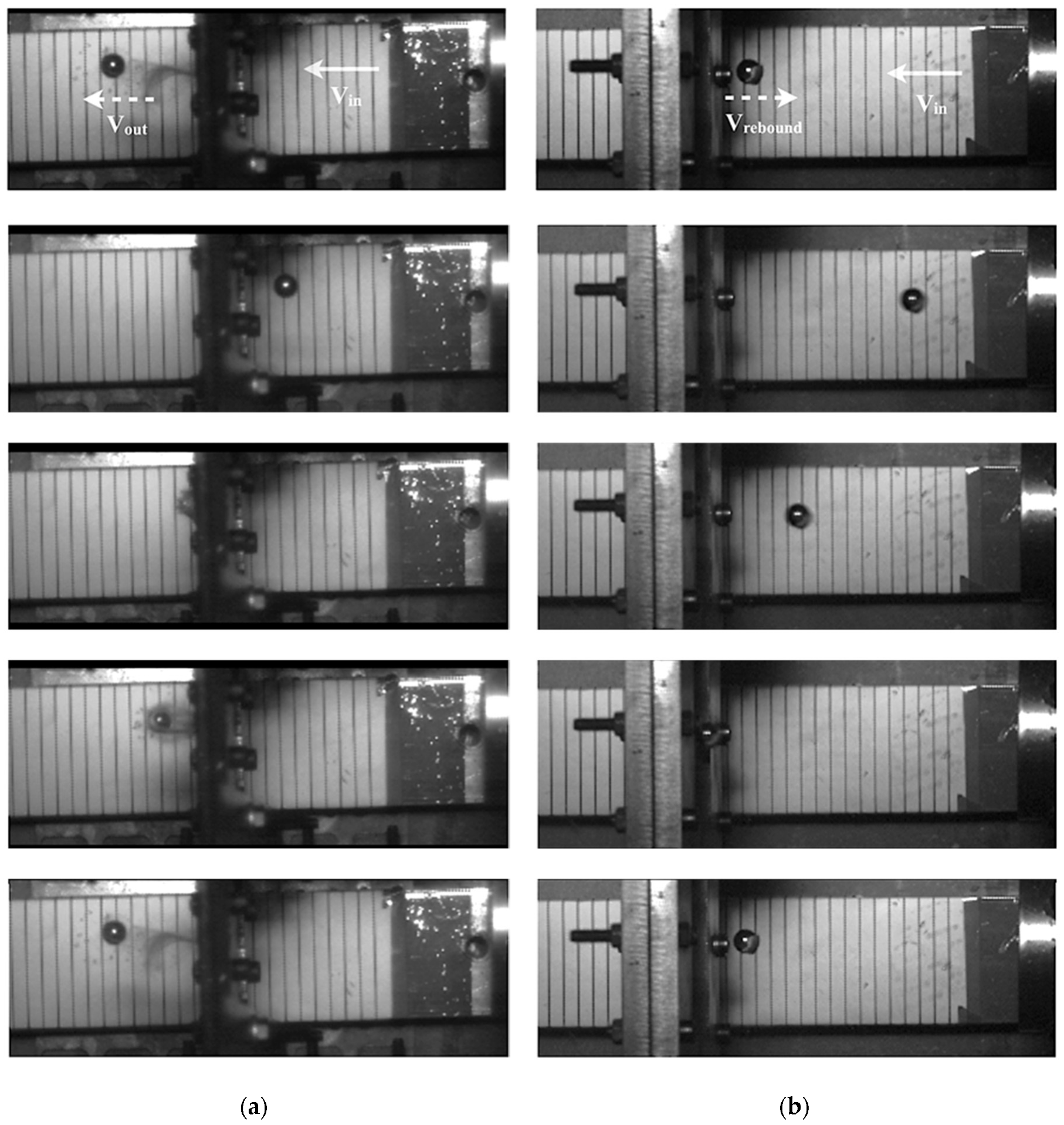
Different numbers of plies, starting from two and up to eight, and different orientations were selected for the testing. In some tests, a layer of nitrile rubber was added between the first and the second plies and/or repeated shots were tested on the same specimens. When analysing the data from the high-speed camera, the impact velocity and the exit or rebound velocity were calculated to obtain the energy absorbed during the impact. The differences between and are shown in Figure 11a,b, respectively.
In Table 4, the results of the tests are shown. It can be noticed that from the point of view of the energy absorption, the ply orientation [0/22.5/45/67.5] seems to be the best configuration.
As expected, the results clearly show that an increase in the number of plies increases the capability of the specimen to hold the bullet. In all the tests with only two layers of fabric, the bullet passed through the specimen with only a small change in the impact velocity. Increasing the number of plies, the number of shots needed for full perforation increased as well.
The ply orientation remarkably affects the behaviour of the specimen and the orientation [0/22.5/45/67.5] seems to be the best four-ply configuration among those tested; this is consistent with previous ballistic tests, as in [60] The presence of rubber seems not to significantly enhance the perforation resistance; however, at the moment, no conclusive results can be drawn for this configuration and additional tests are required.
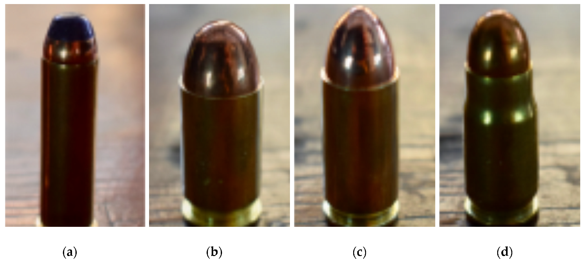
In the case of eight plies, the configuration, [0/45]4, seems to be well adequate to contain the projectiles in lab conditions. Following ballistic tests in the lab, specimens made of eight and 16 plies ([0/45]4 or 8) were tested in a shooting range using different firearms and bullets (Figure 12).
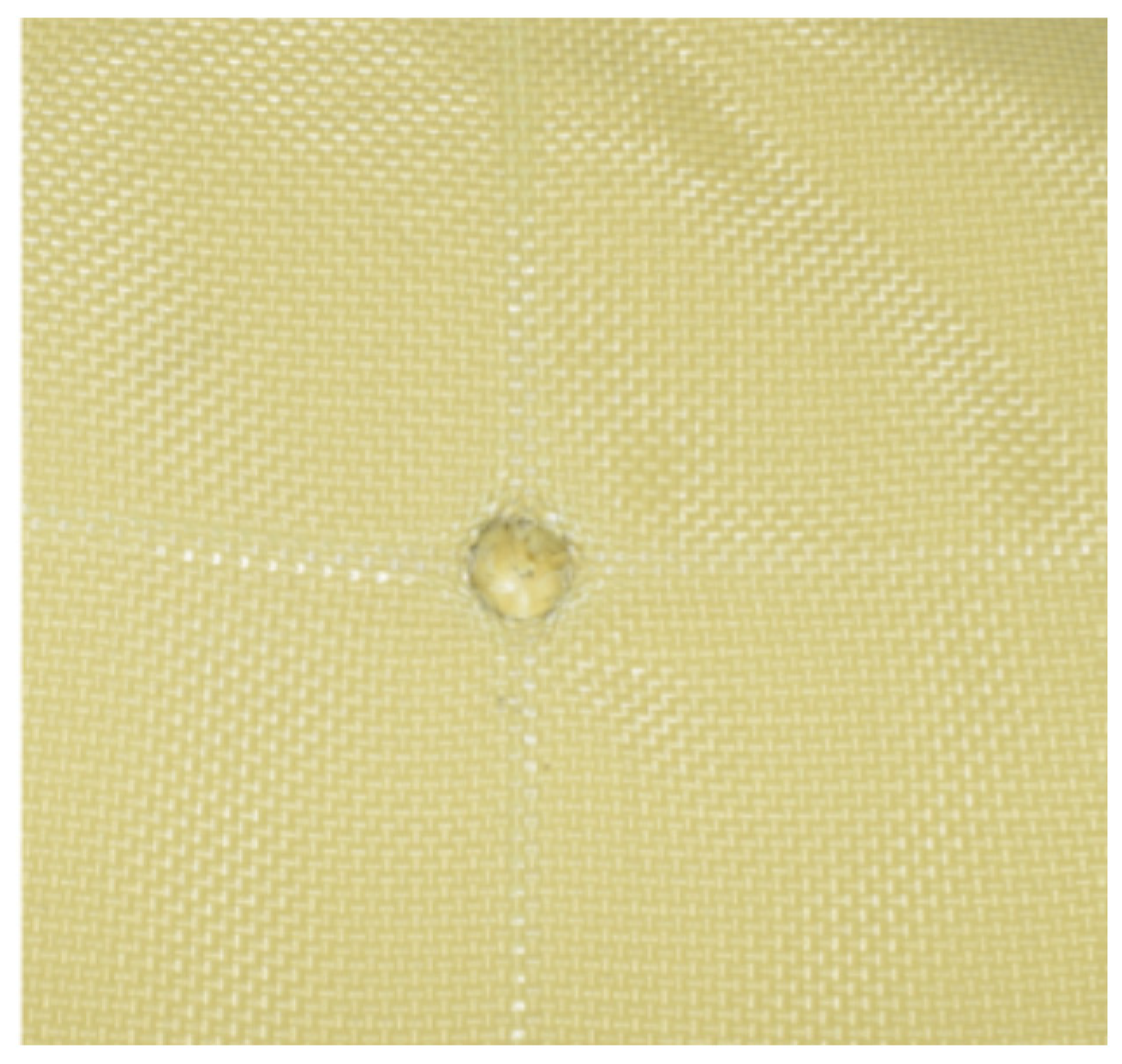
Shots at about 310 m/s with about round nose bullets (45 ACP, 11.43 mm diameter) resulted as well contained with 16 plies and in most cases, also with eight plies (Figure 13). Even when perforation was attained, usually with repeated shots, although the bullet exit speed could not be measured, a consistent loss of kinetic energy was evident in all cases and the bullets could be collected by a light expanded polystyrene plate.
As result of the ballistic testing, it was deemed that a blanket of 8+ plies should allow a consistent protection of the detecting radar sensor from an accidental blast of a small power mine. Considering that the demining personnel is already partially protected by a proper suit, the use of such a blanket may provide additional safety also to the person handling the instrumentation.
4.3. Blanket Impact on GPR Data
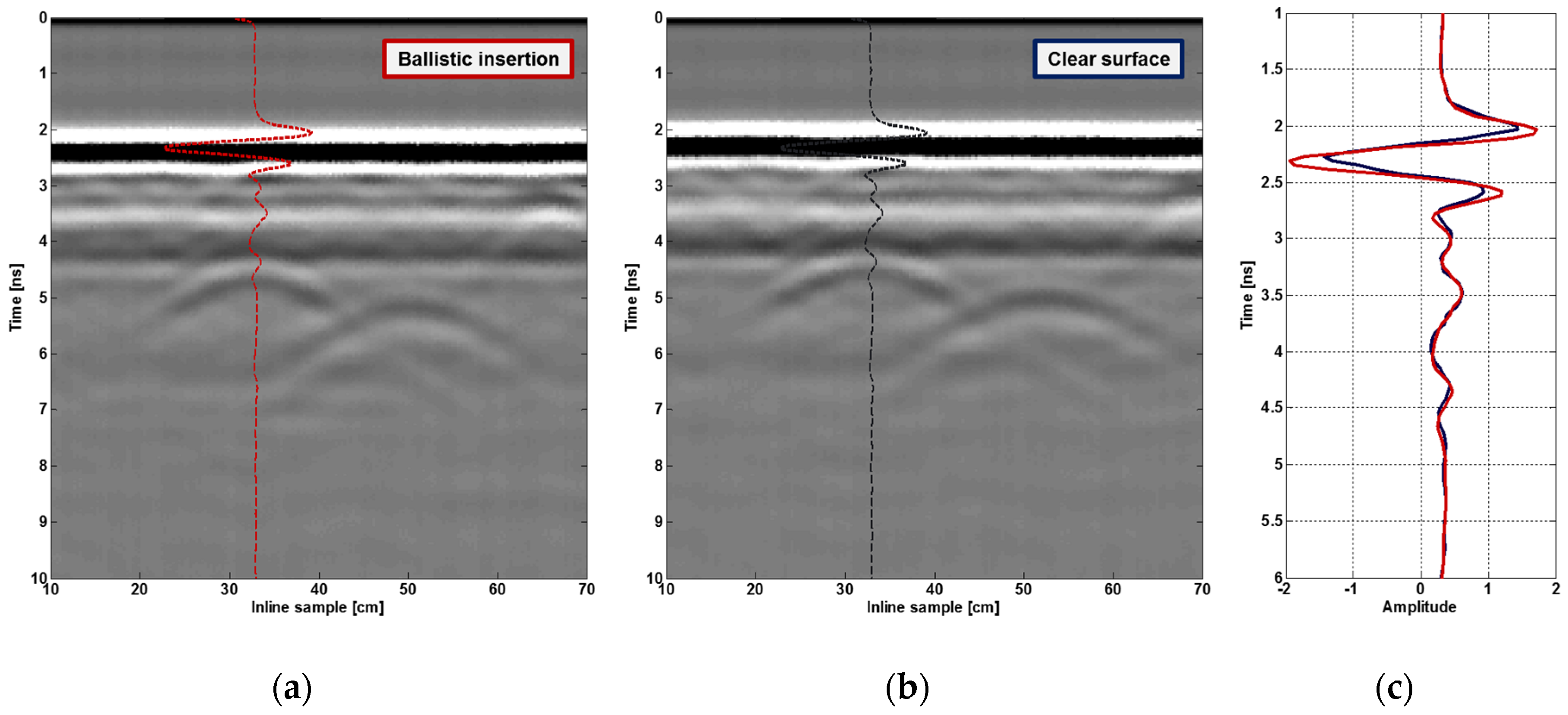
A final experimental activity has been performed to validate the assumption that the described ballistic blanket does not introduce any performance degradation on the radar results, compared to the ideal situation of the antenna in direct contact with the soil. The results of the test are shown in Figure 14.
No significant differences or quality degradation are produced by the ballistic material, possibly also as a result of the limited thickness, and that its influence on the landmine diffraction is negligible. The blanket indeed slightly improves the coupling performance due to a less pronounced transition between the air and soil, as noticeable from the ground reflection event in Figure 14c.
5. Detection Performance Results
Being able to detect and localise buried landmines with high precision in an automatic way is still considered a challenging task due to the many different variables that characterise the problem. The development of safe and robust techniques designed for landmine clearance should build on data, including as many details as possible and exhibiting features that are as much scenario-agnostic as possible.
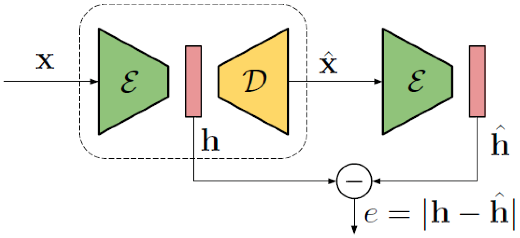
To characterise the performance of the developed system, a method based on convolutional neural networks (CNNs) applied to GPR data, to detect the presence of buried objects not coherent with the surrounding ground, has been evaluated. This data classification is based on an anomaly detection scheme, in which the autoencoder is trained using only mine-free data in order to learn how to model the soil of interest. At deployment time, the autoencoder recognises the presence of anomalous objects, such as landmines, due to their textural differences with the training data. The architecture is depicted in Figure 15.
The detector is mainly composed of two components, corresponding to the encoder (E), which maps the input GPR image patch x into its so-called hidden representation (h), and the decoder (D), the component responsible for estimating the decoded signal ( ), which is an estimate of the input x. A comparison is then performed between the hidden representation of the original patch and the hidden representation of the autoencoded patch, resulting in a distance value (e) that is used as an indicator of possible anomalies.
The rationale behind this system is the following. The encoder is trained to learn a compact representation of small GPR image patches, representing 2D regions of the underground area to be analysed. At the same time, the decoder is trained to recover an estimate of the input image starting from the compact representation. As only mine-free images are used during training, the decoder will inevitably introduce errors in the reconstructed image whenever it contains evidence of mines, and such errors can be used as the anomaly indicator. For this reason, the distance value e will grow as data containing traces of mines are analysed, as more thoroughly explained in [61]. According to the specific threshold that is applied to the distance metric, and that is selected upon a set of training profiles at the system tuning time, the data will finally be classified as either including a target or not.
The proposed classification method has been evaluated by means of a receiver operating characteristic (ROC) curve, obtained by thresholding the anomaly metric e, previously defined, which represents the numerical criterion defining the false positive/alarm rate performance of the system. The curve represents the probability of correct detection against the probability of false detection, by spanning all possible values of the decision threshold [62,63].
As a measure of the test accuracy, the integral of the ROC, known as area under the curve (AUC) value, has been computed. This measure ranges between 0 (the model is reciprocating the results) and 1 (perfect result), passing through 0.5 (random guess). Data acquired over the sandy test site previously described (hereinafter referred as ) have been considered as a dataset, taking only the first five scans for training, with a mine-free assumption. This allowed us to simulate a practical framework of application where the network is trained in a safe zone and then deployed over the investigated area. The processed area included three inert landmines (SB-33, PFM-1, VS-50), four surrogate models (NR409, M14, VS-50, PROM-1, DM-11), the crushed aluminium can, and the hand grenade.
Such profiles were subdivided into overlapping patches and then fed to the network for training and architecture tuning. During the testing phase, the remaining profiles were accordingly decomposed into patches and proposed to the network for the anomaly prediction process, based on the concept that the presence of a landmine is highlighted if at least one patch shows strong evidence of an anomaly. Numerically, the decomposition was characterized by a patch size of 64 samples, chosen as this could entirely include a diffraction hyperbola, and at the same time save computational resources, and a stride value, defined as the number of samples shifted per slide, of four samples [64].
To justify the previously described configurations, detection performance in the case of a different survey approach and system configuration have been mutually compared, and in particular:
- Multi-polarisation configuration: Jointly exploiting the horizontal and vertical polarisations have shown that such an approach outperforms a single configuration one by six percentage points.
- 3D versus 2D data: Adding the third dimension allows a gain of two to five percentage points.
These results confirm the improvement provided by using volumetric data, instead of sparse 2D profiles, and by accounting for the polarimetric information, even if mostly dealing with geometrically regular objects and a homogeneous soil texture.
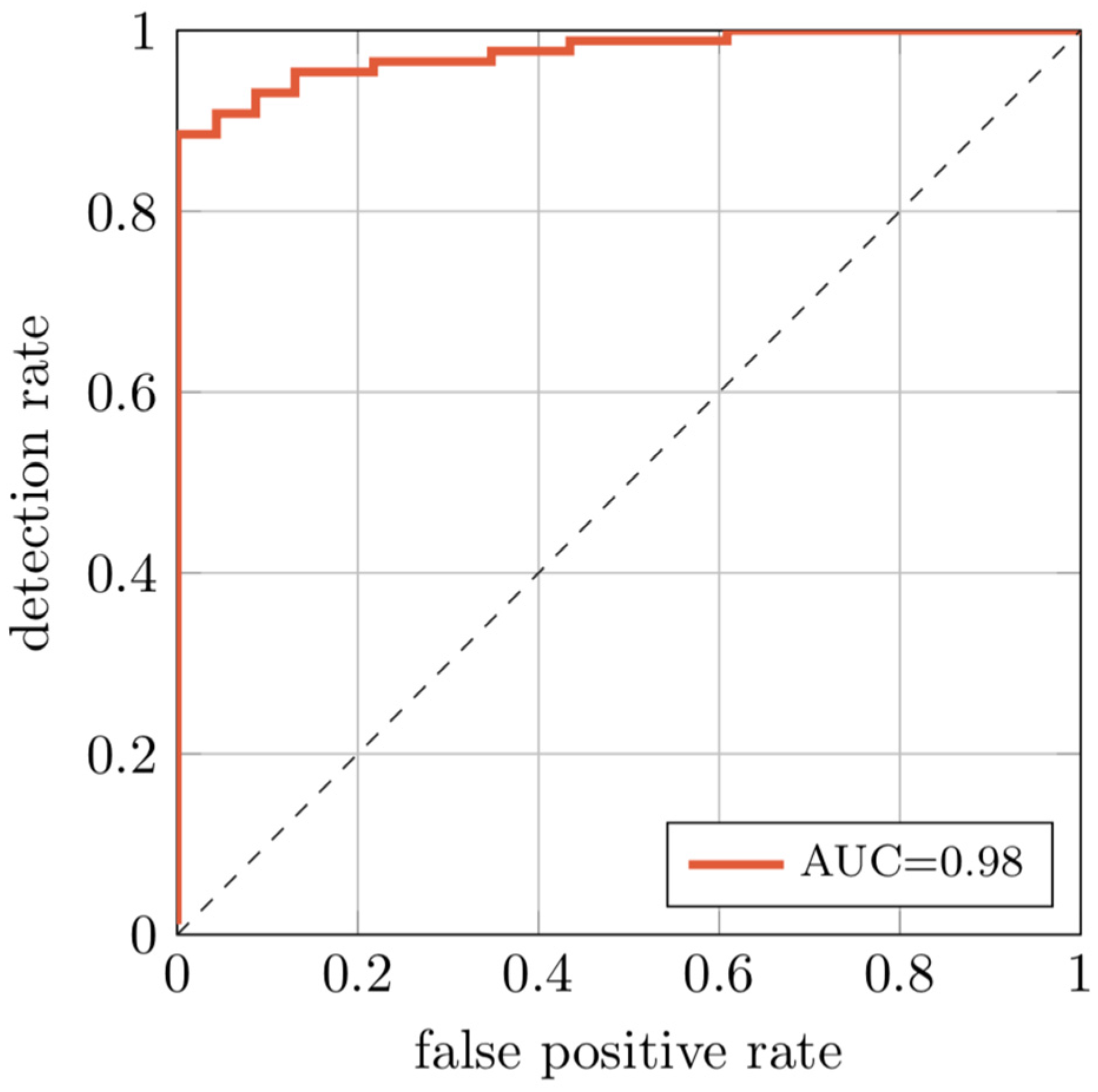
To characterise the performance of the proposed architecture, Figure 16 shows the obtained ROC curve and the resulting AUC score, which reaches a value of approximately 0.98.
The 3D extension on the multi-polarisation data can achieve a detection rate of almost 90% at a false alarm rate of 0%, which means, if considering buried objects rather than radar profiles, the system is able to detect threats without skipping any buried objects. These results show that it is possible to achieve very high detection rates with small false alarm probabilities.
In addition of being computationally light, the training convergence is reached after a few epochs and hence it would be possible to retrain the network for each specific kind of soil just before deployment time, as the solution does not require an excessively large training dataset. The system does not need to be trained on images depicting the specific objects of interests from real acquisitions.
The robustness of the architecture has been tested considering a cross-dataset scenario, employing an additional outdoor facility (hereinafter referred as ) filled with fine sand and subjected to rainfall events preceding the survey. The measured velocity was approximately 10 cm/ns, and hence its relative dielectric is around 9. In such a case, the subsurface texture might not be strictly considered homogeneous, as the shallower layers are expected to be drier compared to the higher moisture level of the deeper layers. Therefore, the hyperbola traces are expected to be less pronounced and the surrounding soil might introduce diffraction-like events due to dielectric property variations. The set-up included three surrogate models (PROM-1, DM-11, and PMN-58), a hand grenade, an aluminium can, a plastic bottle, and a tree root.
The aim of the additional test was to verify how scenario-agnostic the model can be, as the cross-test works by training the network with a set of data different from the testing ensemble. Compared to the previous performance evaluation, the network has been accordingly trained (five mine-free profiles); however, in this case, the anomaly detection process was computed considering the entire ensemble of acquired profiles. The results are provided in Table 5.
The obtained AUC values imply that the system is not strongly conditioned by the kind of soil used during training, and that it could still work even with data on which there is no a priori information or experience. Therefore, these cross-dataset results suggest that such architecture could be pre-trained on a generic dataset and then refined and deployed on a specific soil by acquiring a few background GPR profiles in a safe area. In addition, a first hint on its robustness against a more complex subsurface texture can be extracted, as the AUC result from the test performed on the wetter test site shows good to excellent discrimination accuracy.
6. Discussion and Conclusions
The research has presented the architecture for an affordable and flexible demining equipment based on high resolution GPR technology and powered with deep learning processing techniques.
The proposed system is capable of collecting GPR data with the accuracy required to generate 3D migrated images and sufficiently rich so that an automated data processing architecture based on deep learning can be successfully triggered.
To achieve this, a multi-polarimetric, ground coupled platform has been employed, along with a surface pad for ensuring data regularity and density, so that it is possible to maximise the target contribution and features.
Considering these requirements, the solution has necessitated the development of a dedicated shielding blanket, to be placed between the ground and the surface pad, capable of protecting the surrounding area in case of accidental blasts during operations. The blanket has been assembled by stacking several plies of aramid fibre, so that a proper resistance to flying fragments has been obtained and demonstrated through several ballistic tests. Validation of the acquired data shows that the system provides excellent detection accuracy without extensive image pre-processing. In addition, the system does not need to be trained on images depicting the specific objects of interest from real acquisitions, which is of particular importance considering the wide variability of possible targets and environments. With this approach, it is possible to acquire a limited number of radargrams of controlled mine-free fields, and then deploy the system to detect objects never seen before.
Given the described promising performance, future works will be focused on discriminating anomalies due to actual landmines or different buried objects, so that a proper classification scheme can be included, as well as on the evaluation of the system robustness in the case of less cooperative soil conditions. Another considered feature will be the integration between the shielding blanket and the acquisition pad, so that compact and flexible equipment can be finally produced. The potential applications of such platforms may not be limited to demining operations, but might include a number of additional security applications, such as search and rescue, through wall imaging and safe structure inspection.
Author Contributions
Conceptualization, F.L., M.L. and L.A.D.L.; Methodology, F.L., F.P. and G.J.; Software, F.P. and P.B.; Writing–original draft, F.L., P.B. and G.J.; Writing–review & editing, M.L. and L.A.D.L. All authors have read and agreed to the published version of the manuscript.
Funding
This work has been partially supported by the project PoliMIne (Humanitarian Demining GPR System), funded by Polisocial Award from Politecnico di Milano, Milan, Italy.
Acknowledgments
The authors are grateful to IDS GeoRadar for the provision of the GPR equipment.
Conflicts of Interest
The authors declare no conflict of interest.
References
- Daniels, D.J. Ground Penetrating Radar, 2nd ed.; The Institution of Electrical Engineers: London, UK, 2004; pp. 154–196. [Google Scholar]
- Taylor, J.D. Advanced Ultrawideband Radar: Signals, Targets, and Applications, 1st ed.; CRC Press: Boca Raton, FL, USA, 2017; pp. 20–44. [Google Scholar]
- Wisniewski, K.D.; Pringle, J.K.; Allen, D.; Wilson, G.E. Wildlife Crime: The application of forensic geoscience to assist with criminal investigations. Forensic Sci. Int. 2019, 294, e11–e18. [Google Scholar] [CrossRef] [PubMed]
- Benedetto, A.; Tosti, F.; Ciampoli, L.B.; D’Amico, F. GPR Applications across Engineering and Geosciences Disciplines in Italy: A Review. IEEE J. Sel. Top. Appl. Earth Obs. Remote Sens. 2016, 9, 2952–2965. [Google Scholar] [CrossRef]
- Barone, P.M.; Di Maggio, R.M. Forensic geophysics: Ground penetrating radar (GPR) techniques and missing person investigations. Forensic Sci. Res. 2019, 4, 337–340. [Google Scholar] [CrossRef] [PubMed] [Green Version]
- Yakushev, V.M.; Kataev, S.G.; Kerimov, A.G.; Pyadukhov, D.S. Some peculiarities of using GPR for detection of alive humans under the collapsed buildings. Eng. Min. Geophys. 2018, 1, 1–7. [Google Scholar]
- Diamanti, N.; Annan, A.P.; Giannakis, I. Predicting GPR performance for buried victim search & rescue. In Proceedings of the 16th International Conference on Ground Penetrating Radar, Hong Kong, China, 13–16 June 2016. [Google Scholar]
- Van Schoor, M.; Nienaber, W.C.; Marais-Werner, A. A controlled monitoring study of simulated clandestine graves using 3D ground penetrating radar. Near Surf. Geophys. 2019, 15, 274–284. [Google Scholar] [CrossRef] [Green Version]
- Geneva International Centre for Humanitarian Demining. Manual Demining—GICHD. Available online: https://www.gichd.org/resources/other-resources/technology-subject-archives/detail/technology/manual-demining (accessed on 21 February 2020).
- International Mine Action Standards, 2001. Available online: http://www.mineactionstandards.org/ (accessed on 21 February 2020).
- Generic SOPs, Manual Demining. Available online: http://www.nolandmines.com/Generic_SOPs/V2.1%20Generic%20SOPs%20Chap%206%20Manual%20demining.pdf (accessed on 21 February 2020).
- Robledo, L.; Carrasco, M.; Mery, D. A survey of land mine detection technology. Int. J. Remonte Sens. 2009, 30, 2399–2410. [Google Scholar] [CrossRef]
- Daniels, D.J. A review of GPR for landmine detection. Sens. Imag. Int. J. 2006, 7, 90–123. [Google Scholar] [CrossRef]
- Daniels, D.J. An assessment of the fundamental performance of GPR against buried landmines. Proc. SPIE 2007, 6553, 65530G. [Google Scholar]
- Lombardi, F.; Griffiths, H.D.; Balleri, A. Landmine internal structure detection from ground penetrating radar images. In Proceedings of the 2018 IEEE Radar Conference, Oklahoma City, OK, USA, 23–27 April 2018. [Google Scholar]
- Genc, A.; Akar, G.B. Combination of physics-based and image-based features for landmine identification in ground penetrating radar data. J. Appl. Remote Sens. 2019, 13, 026503. [Google Scholar] [CrossRef]
- Groenenboom, J.; Yarovoy, A. Data processing and imaging in GPR system dedicated for landmine detection. Subsurf. Sens. Technol. Appl. 2002, 3, 387–402. [Google Scholar] [CrossRef]
- Camilo, J.A.; Collins, L.M.; Malof, J.M. A large comparison of feature-based approaches for buried target classification in forward-looking ground-penetrating radar. IEEE Trans. Geosci. Remote Sens. 2017, 56, 547–558. [Google Scholar] [CrossRef]
- Savelyev, T.G.; Van Kempen, L.; Sahli, H.; Sachs, J.; Sato, M. Investigation of time–frequency features for GPR landmine discrimination. IEEE Trans. Geosci. Remote Sens. 2006, 45, 118–129. [Google Scholar] [CrossRef]
- Ratto, C.R.; Torrione, P.A.; Collins, L.M. Exploiting ground-penetrating radar phenomenology in a context-dependent framework for landmine detection and discrimination. IEEE Trans. Geosci. Remote Sens. 2010, 49, 1689–1700. [Google Scholar] [CrossRef]
- Newnham, P.; Daniels, D.J. Market for advanced humanitarian mine detectors. Proc. SPIE 2001, 4394. [Google Scholar] [CrossRef]
- Takahashi, K.; Preetz, H.; Igel, J. Soil properties and performance of landmine detection by metal detector and ground-penetrating radar—Soil characterisation and its verification by a field test. J. Appl. Geophys. 2011, 73, 368–377. [Google Scholar] [CrossRef]
- Takahashi, K.; Igel, J.; Preetz, H. Clutter Modeling for Ground-Penetrating Radar Measurements in Heterogeneous Soils. IEEE J. Sel. Top. Appl. Earth Obs. Remote Sens. 2011, 4, 739–747. [Google Scholar] [CrossRef]
- Paglieroni, D.W.; Chambers, D.H.; Mast, J.E.; Bond, S.W.; Reginald Beer, N. Imaging Modes for Ground Penetrating Radar and Their Relation to Detection Performance. IEEE J. Sel. Top. Appl. Earth Obs. Remote Sens. 2015, 8, 1132–1144. [Google Scholar] [CrossRef]
- Geneva International Centre for Humanitarian Demining. Available online: http://www:gichd:org/resources/publications/ (accessed on 21 February 2020).
- Marsh, L.; van Verre, W.; Davidson, J.; Gao, X.; Podd, F.; Daniels, D.J.; Peyton, A. Combining electromagnetic spectroscopy and ground-penetrating radar for the detection of anti-personnel landmines. Sensors 2019, 19, 3390. [Google Scholar] [CrossRef] [Green Version]
- Daniels, D.J.; Braunstein, J.; Nevard, M. Using minehound in Cambodia and Afghanistan. J. ERW Mine Action 2014, 18, 46–50. [Google Scholar]
- Steinway, W.J.; Perry, L.; Maningo, R.; Ngan, P.; Locke, M. AN/PSS-14 mine detection performance on beaches and in the surf zone. Proc. SPIE 2004, 5415. [Google Scholar] [CrossRef]
- Feng, X.; Sato, M.; Liu, C. Subsurface Imaging Using a Handheld GPR MD System. IEEE Geosci. Remote Sens. Lett. 2012, 9, 659–662. [Google Scholar] [CrossRef]
- Davenport, G.C. Remote Sensing Technology in Forensic Investigations: Geophysical Techniques to Locate Clandestine Graves and Hidden Evidence, 1st ed.; CRC Press: Boca Raton, FL, USA, 2017. [Google Scholar]
- Wen, H.; Wu, W.; Zheng, X.; Guo, J. Application and Development Trend of Radar Detection Technology in Mine Rescue. In Proceedings of the 11th International Mine Ventilation Congress, Xi’an, China, 14–20 September 2018. [Google Scholar]
- Núñez-Nieto, X.; Solla, M.; Gómez-Pérez, P.; Lorenzo, H. GPR signal characterization for automated landmine and UXO detection based on machine learning techniques. Remote Sens. 2014, 6, 9729–9748. [Google Scholar] [CrossRef] [Green Version]
- Reichman, D.; Collins, L.M.; Malof, J.M. On choosing training and testing data for supervised algorithms in ground-penetrating radar data for buried threat detection. IEEE Trans. Geosci. Remote Sens. 2017, 56, 497–507. [Google Scholar] [CrossRef]
- Malof, J.M.; Reichman, D.; Collins, L.M. How do we choose the best model? The impact of cross-validation design on model evaluation for buried threat detection in ground penetrating radar. Proc. SPIE 2018, 10628, 106280C. [Google Scholar]
- Giovanneschi, F.; Mishra, K.V.; Gonzalez-Huici, M.A.; Eldar, Y.C.; Ender, J.H. Dictionary Learning for Adaptive GPR Landmine Classification. IEEE Trans. Geosci. Remote Sens. 2019, 57, 10036–10055. [Google Scholar] [CrossRef] [Green Version]
- Besaw, L.E.; Stimac, P.J. Deep convolutional neural networks for classifying gpr b-scans. Proc. SPIE 2015, 9454. [Google Scholar] [CrossRef]
- Lameri, S.; Lombardi, F.; Bestagini, P.; Lualdi, M.; Tubaro, S. Landmine detection from GPR data using convolutional neural networks. In Proceedings of the 25th European Signal Processing Conference, Kos, Greece, 28 August–2 September 2017. [Google Scholar]
- Picetti, F.; Testa, G.; Lombardi, F.; Bestagini, P.; Lualdi, M.; Tubaro, S. Convolutional Autoencoder for Landmine Detection on GPR Scans. In Proceedings of the 41st International Conference on Telecommunications and Signal Processing, Athens, Greece, 4–6 July 2018. [Google Scholar]
- Available online: https://www.gichd.org/fileadmin/GICHD-resources/rec-documents/external-documents/Falkland-Islands-Malvinas-Exploitation-Report-2013.pdf (accessed on 21 February 2020).
- Available online: https://www.nato.int/cps/en/natolive/news_108818.htm (accessed on 21 February 2020).
- Available online: https://www.mineactionstandards.org/fileadmin/user_upload/IMAS_09-10_Ed2-Am6.pdf (accessed on 21 February 2020).
- Daniels, D.J. Set-up of an ideal landmine test site for GPR. Proc. SPIE 2005, 5794. [Google Scholar] [CrossRef]
- Lualdi, M. True 3D acquisition using GPR over small areas: A cost effective solution. In Proceedings of the 24th Symposium on the Application of Geophysics to Engineering and Environmental Problems, Charleston, SC, USA, 10–14 April 2011. [Google Scholar]
- Lualdi, M.; Zanzi, L. Testing a safe acquisition procedure for an effective application of GPR to security operations. In Proceedings of the 18th Symposium on the Application of Geophysics to Engineering and Environmental Problems, Atlanta, GA, USA, 3 April 2005. [Google Scholar]
- Kang, W.; Kim, C.; Kim, J.H.; Park, S.; Son, J.; Jeong, S.; Kim, K. The effect of the antenna height on quality of bistatic GPR data. In Proceedings of the 9th International Workshop on Advanced Ground Penetrating Radar, Edinburgh, UK, 28–30 June 2017. [Google Scholar]
- Gao, X.; Podd, F.J.; Van Verre, W.; Daniels, D.J.; Peyton, A.J. Investigating the Performance of Bi-Static GPR Antennas for Near-Surface Object Detection. Sensors 2019, 19, 170. [Google Scholar] [CrossRef] [Green Version]
- Lambot, S.; Antoine, M.; Vanclooster, M.; Slob, E.C. Effect of soil roughness on the inversion of off-ground monostatic GPR signal for noninvasive quantification of soil properties. Water Resour. Res. 2006, 42, W03403. [Google Scholar] [CrossRef] [Green Version]
- Roberts, R.L.; Daniels, J.J. Analysis of GPR polarization phenomena. J. Environ. Eng. Geophys. 1996, 1, 139–157. [Google Scholar] [CrossRef]
- Lombardi, F.; Lualdi, M. Multi-azimuth ground penetrating radar surveys to improve the imaging of complex fractures. Geoscience 2018, 8, 425. [Google Scholar] [CrossRef] [Green Version]
- Daniels, J.J.; Wielopolski, L.; Radzevicius, S.; Bookshar, J. 3D GPR polarization analysis for imaging complex objects. In Proceedings of the 16th Symposium on the Application of Geophysics to Engineering and Environmental Problems, San Antonio, TX, USA, 6 April 2003. [Google Scholar]
- Lombardi, F.; Griffiths, H.D.; Wright, L.; Balleri, A. Dependence of landmine radar signature on aspect angle. IET Radar Sonar Navig. 2017, 11, 892–902. [Google Scholar] [CrossRef] [Green Version]
- Leckebusch, J. Problems and solutions with GPR data interpretation: Depolarization and data continuity. Archaeolog. Prosp. 2011, 18, 303–308. [Google Scholar] [CrossRef]
- Verdonck, L.; Taelman, D.; Vermeulen, F.; Docter, R. The impact of spatial sampling and migration on the interpretation of complex archaeological ground-penetrating radar data. Archaeolog. Prosp. 2015, 22, 91–103. [Google Scholar] [CrossRef]
- Lombardi, F.; Griffiths, H.D.; Lualdi, M. Sparse Ground Penetrating Radar Acquisition: Implication for Buried Landmine Localization and Reconstruction. IEEE Geosci. Remote Sens. Lett. 2019, 16, 362–366. [Google Scholar] [CrossRef]
- BlastTac. Available online: http://www.blasttac.com/ (accessed on 21 February 2020).
- FLY-BAG Project Homepage. Available online: http://www.fly-bag.eu/ (accessed on 21 February 2020).
- Navin, D.; Ostman, J.R.E.; Lewis, P.; Tamulonis, F. Ballistic Curtain Cordon System. U.S. Patent US20180156577, 4 December 2017. Available online: https://patentscope.wipo.int/search/en/detail.jsf?docId=US219629809&_cid=P11-K6VY7F-94336-1 (accessed on 21 February 2020).
- Pirvu, C.; Deleanu, L. Ballistic Testing of Armor Panels Based on Aramid Fibers. In Ballistics; Osheku, C., Ed.; IntechOpen: London, UK, 2019. [Google Scholar] [CrossRef] [Green Version]
- Zhu, D.; Vaidya, A.; Mobasher, B.; Rajan, S.D. Finite element modeling of ballistic impact on multi-layer Kevlar 49 fabrics. Compos. Part B Eng. 2014, 56, 254–262. [Google Scholar] [CrossRef]
- Wang, Y.; Chen, X.; Young, R.; Kinloch, I. An experimental study of the effect of ply orientation on ballistic impact performance of multi-ply fabric panels. Text. Res. J. 2016, 86, 34–43. [Google Scholar] [CrossRef]
- Bestagini, P.; Lombardi, F.; Lualdi, M.; Picetti, F.; Tubaro, S. Landmine Detection Using Autoencoders on Multi-polarization GPR Volumetric Data. arXiv 2018, arXiv:1810.01316. [Google Scholar]
- Lee, W.H.; Gader, P.D.; Wilson, J.N. Optimizing the area under a receiver operating characteristic curve with application to landmine detection. IEEE Trans. Geosci. Remote Sens. 2007, 45, 389–397. [Google Scholar] [CrossRef]
- González-Huici, M.A.; Catapano, I.; Soldovieri, F. A comparative study of GPR reconstruction approaches for landmine detection. IEEE J. Sel. Top. Appl. Earth Obs. Remote Sens. 2014, 7, 4869–4878. [Google Scholar] [CrossRef]
- Reichman, D.; Collins, L.M.; Malof, J.M. Some good practices for applying convolutional neural networks to buried threat detection in Ground Penetrating Radar. In Proceedings of the 9th International Workshop on Advanced Ground Penetrating Radar, Edinburgh, UK, 28–30 June 2017. [Google Scholar]
Figure 1.
Employed targets. From left to right, first row: R2M2 (surrogate), PMN (surrogate), PMA-2 (surrogate), NR409 (surrogate), M14 (surrogate), VS-50 (surrogate). Second row: PROM-1 (surrogate), P48 (surrogate), MIAPDV-59 (surrogate), DM-11 (surrogate), VS-50 (inert), SB-33 (inert). Third row: PFM-1 (inert), tree root, crushed can, hand grenade, oil sand rock, and sand-filled plastic bottle.

Figure 2.
Ground penetrating radar (GPR) platform employed for the experimentation and internal geometry.
Figure 2.
Ground penetrating radar (GPR) platform employed for the experimentation and internal geometry.

Figure 3.
The GPR frequency evaluation results. (a) Buried VS-50 landmine. (b) Buried SB-33 landmine. (c) 2 GHz equipment profile. (d) 3 GHz equipment profile. The targets are highlighted.
Figure 3.
The GPR frequency evaluation results. (a) Buried VS-50 landmine. (b) Buried SB-33 landmine. (c) 2 GHz equipment profile. (d) 3 GHz equipment profile. The targets are highlighted.

Figure 4.
The GPR profiles with varying antenna heights. (a) Height: 0 cm. (b) Height: 5 cm. (c) Height: 10 cm.
Figure 4.
The GPR profiles with varying antenna heights. (a) Height: 0 cm. (b) Height: 5 cm. (c) Height: 10 cm.

Figure 5.
Amplitude spectrum characteristics with varying antenna elevations.

Figure 6.
Radar cross section (RCS) diagram acquired for a mortar shell and an antipersonnel landmine.
Figure 6.
Radar cross section (RCS) diagram acquired for a mortar shell and an antipersonnel landmine.

Figure 7.
The effects of the acquisition procedure on the data reconstruction. (a) Data sampling degradation, the sample spacing is indicated in each frame. (b) Data positioning degradation, the accuracy radius is indicated in each frame.
Figure 7.
The effects of the acquisition procedure on the data reconstruction. (a) Data sampling degradation, the sample spacing is indicated in each frame. (b) Data positioning degradation, the accuracy radius is indicated in each frame.

Figure 8.
Tensile curves of the Aramid Style 101 fabric.

Figure 9.
Test equipment.

Figure 10.
Details of the employed support for the ballistics trials. (a) Top layer, rear side; (b) Bottom layer, front side; (c) Assembled frame including the specimen under test, impact side.
Figure 10.
Details of the employed support for the ballistics trials. (a) Top layer, rear side; (b) Bottom layer, front side; (c) Assembled frame including the specimen under test, impact side.

Figure 11.
Screen shots from the high-speed camera. (a) Two plies (perforated), a bullet passing through; (b) Four plies (not perforated), a bullet being rebounded.
Figure 11.
Screen shots from the high-speed camera. (a) Two plies (perforated), a bullet passing through; (b) Four plies (not perforated), a bullet being rebounded.

Figure 12.
Bullets employed in the ballistic tests. (a) 357 Magnum. (b) 45 ACP. (c) 9 mm IMI. (d) 7.65 mm Parabellum.
Figure 12.
Bullets employed in the ballistic tests. (a) 357 Magnum. (b) 45 ACP. (c) 9 mm IMI. (d) 7.65 mm Parabellum.

Figure 13.
Aramid blanket (eight plies), after a shot with 45 ACP bullet.

Figure 14.
Comparison of the GPR profile results. (a) Ballistic blanket included. (b) Clear surface. (c) Signal analysis.
Figure 14.
Comparison of the GPR profile results. (a) Ballistic blanket included. (b) Clear surface. (c) Signal analysis.

Figure 15.
Detector pipeline: The acquired GPR image x is processed by the encoder E to obtain the hidden representation h. This is decoded by D into an estimate of the image , which is processed again by the encoder E. The error e is used to trigger landmine detection.
Figure 15.
Detector pipeline: The acquired GPR image x is processed by the encoder E to obtain the hidden representation h. This is decoded by D into an estimate of the image , which is processed again by the encoder E. The error e is used to trigger landmine detection.

Figure 16.
The detection rate of the proposed system for different false alarm rates. The area under the curve (AUC) is close to 1.
Figure 16.
The detection rate of the proposed system for different false alarm rates. The area under the curve (AUC) is close to 1.


Table 1.
Landmine test site population details.
| Designation | Type | Diameter | Height | Material |
|---|---|---|---|---|
| R2M2 | Surrogate | 68 mm | 63 mm | Epoxy resin |
| PMN | 111 mm | 56 mm | ||
| PMA-2 | 86 mm | 60 mm | ||
| NR409 | 81 mm | 26 mm | ||
| M14 | 55 mm | 39 mm | ||
| VS-50 | 89 mm | 45 mm | ||
| PROM-1 | 75 mm | 255 mm | ||
| P4B | 72 mm | 46 mm | ||
| MIAPDV-59 | 60 mm | 52 mm | ||
| DM-11 | 92 mm | 36 mm | ||
| VS-50 | Inert | 90 mm | 45 mm | Plastic |
| SB-33 | 85 mm | 30 mm | Polycarbonate | |
| PFM-1 | 120 mm (length) 20 mm (width) | 61 mm | Plastic | |
| Tree root | Clutter | 30 mm | 280 mm | Wood |
| Crushed can | 58 mm | 145 mm | Aluminium | |
| Hand grenade | 89 mm (length) | 10 mm | Metal | |
| Rock | 110 mm (length) 70 mm (width) | 40 mm | Oil sand | |
| Plastic bottle | 63 mm | 200 mm | Sand filled |
Table 2.
GPR acquisition details.
| Parameter | Value |
|---|---|
| Inline sampling | 0.4 cm |
| Crossline sampling | 0.8 cm |
| Time sampling | 0.0522 ns |
| Time window | 20 ns |
| Antenna separation | 6 cm |
| Antenna height | <1 cm |
| Antenna frequency | 2 GHz |
| System bandwidth | 2 GHz |
Table 3.
The mechanical properties of the Aramid Style 101 fabric.
| Strength 0° Warp (N/cm) | Strength 90° Weft (N/cm) | Stiffness 0° Warp (KN/cm) | Stiffness 90° Weft (KN/cm) |
|---|---|---|---|
| 2920 | 2770 | 66 | 63 |
Table 4.
List of the tests and results. The letter G indicates the presence of a rubber layer. The code 1st… 4th indicates the number of repeated shots in the same target area.
Table 4.
List of the tests and results. The letter G indicates the presence of a rubber layer. The code 1st… 4th indicates the number of repeated shots in the same target area.
| (Plies Orientation) × (Shot Number) | (m/s) | (m/s) | (m/s) | Material Perforation |
|---|---|---|---|---|
| [0/45/0/45] × 1st | 212 | 33 | - | No |
| [0/45/0/45] × 2nd | 185 | 45 | - | No |
| [0/45/0/45] × 3rd | 210 | - | 48 | Yes |
| [0/22.5/45/67.5] × 1st | 200 | 30 | - | No |
| [0/22.5/45/67.5] × 2nd | 175 | 40 | - | No |
| [0/22.5/45/67.5] × 3rd | 140 | 57 | - | No |
| [0/22.5/45/67.5] × 4th | 210 | 46 | - | No |
| [0/45/0/45/0/45/0/45] | 210 | 55 | - | No |
| [0/G/45/0/45] × 1st | 170 | 27 | - | 1st ply only |
| [0/G/45/0/45] × 2nd | 210 | - | - | Stuck in rubber ply |
| [0/G/22.5/45/67.5] × 1st | 210 | 16 | - | 1st ply only |
| [0/G/22.5/45/67.5] × 2nd | 210 | - | 82 | Yes |
| [0/G/45/0/45] × 2nd | 210 | - | - | Stuck in rubber ply |
Table 5.
The results of the cross-tests.
| Train T1 Test T1 | Train T2 Test T2 | Train T1 Test T2 | Train T2 Test T1 |
|---|---|---|---|
| 0.98 | 0.93 | 0.81 | 0.84 |
© 2020 by the authors. Licensee MDPI, Basel, Switzerland. This article is an open access article distributed under the terms and conditions of the Creative Commons Attribution (CC BY) license (http://creativecommons.org/licenses/by/4.0/).
Share and Cite
MDPI and ACS Style
Lombardi, F.; Lualdi, M.; Picetti, F.; Bestagini, P.; Janszen, G.; Di Landro, L.A. Ballistic Ground Penetrating Radar Equipment for Blast-Exposed Security Applications. Remote Sens. 2020, 12, 717. https://doi.org/10.3390/rs12040717
AMA Style
Lombardi F, Lualdi M, Picetti F, Bestagini P, Janszen G, Di Landro LA. Ballistic Ground Penetrating Radar Equipment for Blast-Exposed Security Applications. Remote Sensing. 2020; 12(4):717. https://doi.org/10.3390/rs12040717
Chicago/Turabian StyleLombardi, Federico, Maurizio Lualdi, Francesco Picetti, Paolo Bestagini, Gerardus Janszen, and Luca Angelo Di Landro. 2020. "Ballistic Ground Penetrating Radar Equipment for Blast-Exposed Security Applications" Remote Sensing 12, no. 4: 717. https://doi.org/10.3390/rs12040717
Note that from the first issue of 2016, this journal uses article numbers instead of page numbers. See further details here.