
CPM Signals for Satellite Navigation in the S and C Bands

College of Information & Communication Engineering, Harbin Engineering University, Harbin 150001, China
*
Author to whom correspondence should be addressed.
Sensors 2015, 15(6), 13184-13200; https://doi.org/10.3390/s150613184
Submission received: 13 February 2015
/
Revised: 22 May 2015
/
Accepted: 2 June 2015
/
Published: 5 June 2015
(This article belongs to the Section Remote Sensors)
Abstract
:Frequency allocations in the L band suitable for global navigation satellite system (GNSS) services are getting crowded and system providers face an ever tougher job when they try to bring in new signals and services while maintaining radio frequency compatibility. With the successive opening of the S and C bands to GNSS service, the multi-band combined navigation is predicted to become a key technology for future high-precision positioning navigation systems, and a single modulation scheme satisfying the requirements in each band is a promising solution for reducing user terminal complexity. A universal modulation scheme based on the continuous phase modulation (CPM) family suitable for the above bands’ demands is proposed. Moreover, this paper has put forward two specific CPM signals for the S and C bands, respectively. Then the proposed modulation schemes, together with existing candidates, are comprehensively evaluated. Simulation results show that the proposed CPM signals can not only satisfy the constraint condition of compatibility in different bands well and reduce user terminal complexity, but also provide superior performance in terms of tracking accuracy, multi-path mitigation and anti-jamming compared to other candidate modulation schemes.
1. Introduction
With the recent modernization of GPS and GLONASS signals and the emerging Compass and Galileo systems, the number of navigation satellite signals in space is increasing drastically and anticipated to surpass 400 by 2030. Such a large number of signals will further exacerbate an already crowded radio spectrum in the 1164–1610 MHz L band and negatively impact the performance of all navigation systems sharing these limited resources [1].
In order to solve the above problem, the International Telecommunication Union (ITU) has successively allocated the S band (2483.5–2500 MHz) and C band (5010–5030 MHz) to satellite navigation services. Although signal performance in a single S or C band cannot surpass the L band’s due to the smaller available bandwidth and the higher path losses [2,3,4], the signal combination of L band and S or C band could improve positioning accuracy and timing performance and comprehensively promote the performance of radio navigation services [3,5,6]. Therefore, the multi-band combined navigation and compatibility among different navigation systems has become a research hotspot in recent years [7,8].
Compared to multi-frequency signals in the L band, multi-band multi-frequency signals can not only mostly reduce ionosphere delays and strengthen ionospheric correction capability, but also ease carrier phase integer ambiguity resolution to improve robustness and position accuracy, and enhance the anti-interference ability of GNSS signals [2,3,5,6]. As is well-known, signal structure is one of the decisive factors for GNSS and modulation is one of the key technologies which must be resolved during the system design and upgrading process. CPM has been widely used in the field of satellite communication [9,10], which has high spectrum efficiency and constant-envelope features. Besides, it has many other excellent characteristics, such as a large number of alternative waveforms, flexible parameter adjusment, better compatibility with existing signals and so on.
In the L band, a special subclass of CPM with semi-integer modulation index () greater than one and satisfying a constraint can exhibit a similar spectral main lobe and yield comparable navigation performance compared to conventional binary offset carrier (BOC) denoted as BOC(n, m), where MHz is the spread spectrum code rate, MHz is the frequency of sub-carrier and denotes the CPM signal symbol time [11]. The IRNSS will transmit navigation signals in the lower S band. BPSK(m) and BOC(n, m) centered on a frequency close to 2491 MHz are the specific waveforms [12]. Meanwhile, minimum shift keying (MSK) as a potentially promising C band signal waveform that has been investigated for the Galileo system [13], which is a special case of CPM. Unfortunately, the above modulation schemes can’t meet the requirement of compatibility in the S and C bands very well due to relatively high side lobes. Furthermore, different modulation waveforms employed by each band undoubtedly increase the user terminal complexity in the multi-band combined navigation mode. In view of this, we propose a universal modulation scheme based on the CPM family and design two specific CPM signals as S and C band solutions by virtue of their properties, which will make a single modulation waveform design possible and accelerate the practicality of multi-band combined navigation technology.
The rest of this paper is organized as follows: Section 2 describes the mathematical model and power spectrum density (PSD) of CPM signals. The Section 3 provides a comprehensive evaluation criterion for GNSS signal design and introduces analytical methods in terms of anti-jamming performance. The proposed CPM signals together with other candidates are comprehensively evaluated in Section 4 and Section 5, respectively. Finally, we conclude the paper in Section 6.
2. CPM Signal
2.1. Mathematical Model
The time-domain representation of CPM signals can be expressed as [14,15]:
where the , , and are the symbol energy, symbol period, carrier frequency and initial phase respectively, and is the information-carrying phase denoted as:
where the M-ary data symbols take values , , , , is modulation index of , normally the function is a smooth pulse shape over a finite time interval and zero outside. Thus, by choosing different pulses and varying the parameters and , a great variety of CPM schemes can be obtained. For convenience, we use the notation for a raised cosine pulse of length symbol intervals. For example, 2RC is a raised cosine pulse of length . Likewise, the rectangular pulse of length is denoted as .
Figure 1.
CPM signal generator scheme for GNSS.

The CPM can be decomposed into continuous phase encoder (CPE) and memoryless modulator (MM) [16], which greatly reduces implementation complexity. The signal generation block diagram of CPM as future GNSS modulation is shown in Figure 1, where and are mapping functions of in-phase and quadrature branches, defined as:
where represents the physical tilted phase given by [16]:
with:
where the operator is modulo operator, is the integral of and .
2.2. PSD
As we know, PSD of modulated signals have a direct effect on tracking performance, ability of multi-path mitigation and compatibility, and the PSD of CPM is derived as follows:
If is assumed even, the autocorrelation function of CPM can be given by [17]:
where denotes the correlation time, and is the maximum integer below . According to the Wiener-Khintchine theorem, the PSD of CPM derived from Fourier transformation of is written as:
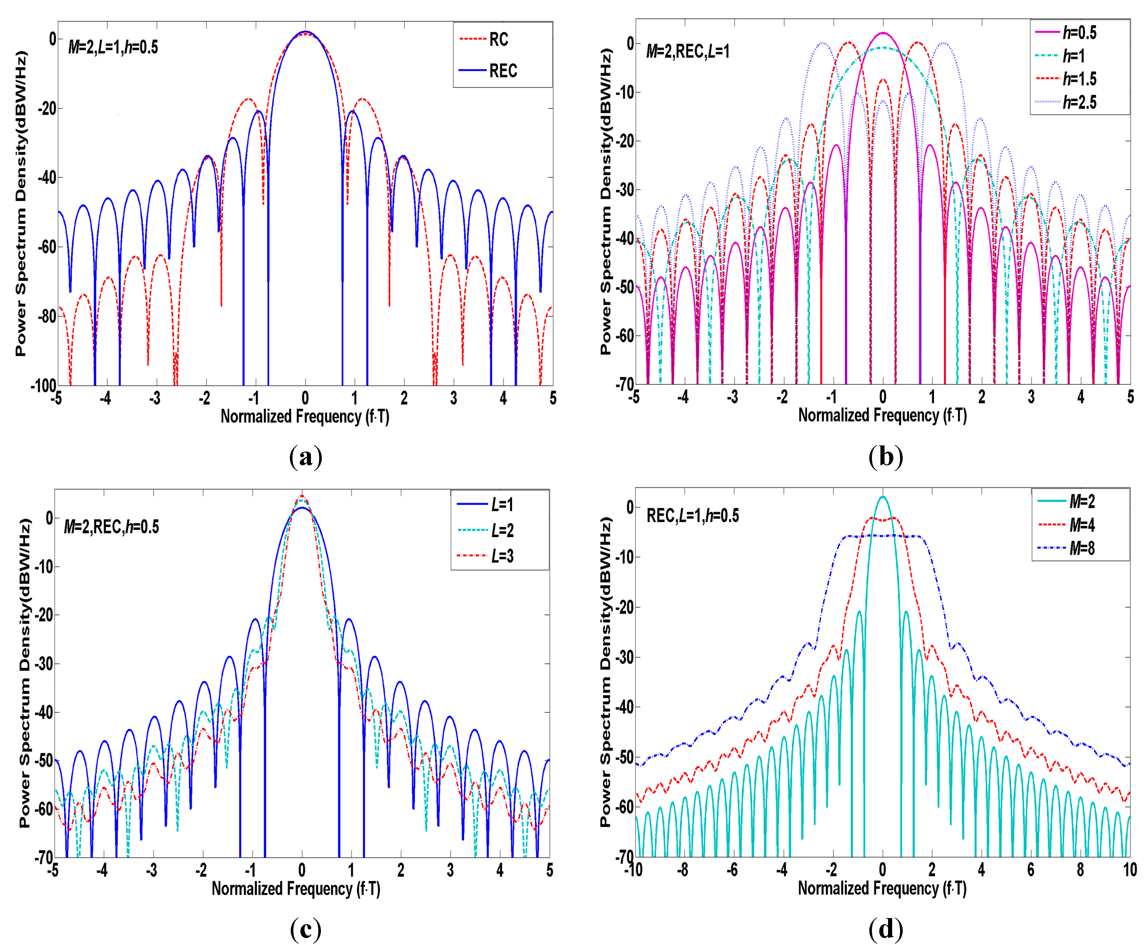
with . It is noteworthy that the parameters including , , and determine the spectral characteristics together, as is shown in Figure 2.
Obviously, a longer or smoother can effectively decrease the PSD amplitude of side lobes and concentrate more energy into the main lobe while a bigger or would tend to extend the main lobe. It is amazing to find that the PSD of CPM behaves like BOC signals with spectrum splitting in the case of . The special subclass of CPM with tuned parameters can resemble the BOC modulation spectrum and yield comparable performance in terms of tracking accuracy, multipath mitigation, anti-jamming, and compatibility [11]. In this instance, if we can design two specific modulation schemes based on the CPM family successfully satisfying the S and C band requirements, that would reduce the complexity of the required hardware and software blocks and accelerate the practicality of multi-band combined navigation technology.
Considering the strict bandwidth restrictions for S and C bands as well as implementation complexity of CPM, this paper puts forward two specific CPM signals with , , and , , denoted as BM2RC and QM2RC for the S and C bands, respectively, whose carrier frequencies are separately close to 2491 MHz and 5020 MHz in the S and C bands.
Figure 2.
(a) PSD of CPM signals with different ; (b) PSD of CPM signals with different ; (c) PSD of CPM signals with different ; (d) PSD of CPM signals with different .
Figure 2.
(a) PSD of CPM signals with different ; (b) PSD of CPM signals with different ; (c) PSD of CPM signals with different ; (d) PSD of CPM signals with different .

3. Evaluation Criterion
The GNSS modulation signal analytical methods are presented in this section and the tracking performance, multi-path mitigation, anti-jamming performance and compatibility are used as performance evaluation standards, which provide significant references on satellite navigation signal design.
3.1. Tracking Performance
Gabor bandwidth and code tracking errors are important technical indexes for evaluating the tracking performance. Based on a coherent early-minus-late (EML) code tracking loop, the code tracking errors in additive white Gaussian noise (AWGN) are defined as [18]:
where the denotes the tracking loop bandwidth, is the PSD of the signal that is normalized to unit power over infinite transmission bandwidth and symmetric to the carrier frequency, denotes the correlation time spacing between the early and late reference signals, is the carrier-to-noise ratio (CNR), is the receiver pre-filtering bandwidth and is the coherent integration time. Assuming that the signal is ideal and is small enough, the Equation (9) in the limit defined as is vanishingly small and becomes:
with:
where and are referred to as the Cramér-Rao lower bound and Gabor bandwidth, respectively. From Equation (10), it is obvious that the Gabor bandwidth can be approximately interpreted as Cramér-Rao lower bound and the greater the Gabor bandwidth, the better the code tracking accuracy.
3.2. Multi-Path Error Envelopes
The multi-path errors is one of the dominant error sources in GNSS. The multi-path error envelopes and average multi-path errors are valuable indexes to evaluate the multi-path mitigation ability. The received base-band signals disturbed by other reflected signals can be expressed as [19]:
where , and are the amplitude, delay and phase of the direct signal. Likewise, , and are the amplitude, delay and phase of reflected signals, and denotes the number of reflected signals. If we only consider one reflected path and use a coherent EML discriminator, the discriminator output can be described as follows [20]:
where and are the delay and carrier phase difference between the multi-path and direct signals with and separately, and denotes the multi-path errors. To explore the theoretical lower bound of the multi-path errors, the cases and corresponding to the worst multi-path errors are considered. By the definition of the Maclaurin series, the Equation (13) can be simplified as:
According to the Wiener-Khintchine theorem, and can be obtained by substituting ‘0’ into Equation (13) and the corresponding first-order derivative, i.e.,
By combining Equations (14)–(16), the multi-path error envelopes can be estimated eventually by:
with multi-path to direct ratio (MDR) namely . The corresponding average multi-path errors can be given by:
where and are the multi-path errors under the conditions and .
3.3. Compatibility
For ensuring normal GNSS work and to realize interoperability to maximize the benefits of GNSS users, good compatibility is necessary. The spectral separation coefficient (SSC) is a fundamental measure of compatibility among GNSS signals and reflects the degree of interference imposed on a signal by other GNSS signals. The SSC is defined as the inner product of PSD between desired and interfering signals, as follows [21,22,23]:
where and are the PSD of the desired and interfering signals separately, where both of them are normalized to unit power over an infinite transmission bandwidth.
3.4. Anti-Jamming Performance
The narrowband-jamming and matched-spectrum-jamming are the main threats to the pseudo code and carrier tracking as well as the demodulation process. In order to effectively evaluate the anti-jamming ability of navigation signals against the above interferences, the paper introduces four parameters, including anti-narrowband-jamming merit factor and anti-matched-spectrum-jamming merit factor for the demodulation process, and the anti-narrowband-jamming merit factors and anti-matched-spectrum-jamming merit factor for the code tracking process.
The demodulation performance mainly lies in the coding properties and effective signal-to-noise ratio of received signals. When there exists noise and one non-white interfering signal with high power, the effective is approximately expressed by:
where denotes the message rate and is the received power of the interfering signal. Neglecting the constant term of , a quantity called anti-jamming merit factor for the demodulation process can be obtained by converting Equation (20) into a dB level version, i.e.:
As for narrowband-jamming, we take a delta function to describe the PSD of the interfering signal as:
where is the carrier frequency offset. Through Equations (19), (21) and (22), we find that the demodulation performance would be deteriorated to a great extent when corresponds to the peak of the desired signal PSD. Thus Equation (21) can be further modified as follows:
Similarly, when is equal to , the lower bound of matched-spectrum-jamming in the demodulation process can be given approximately by:
In terms of coherent EML code tracking loop, the effective is defined by [7,24]:
with code tracking spectral sensitivity coefficient as:
If it is assumed that the interfering power is high enough and is relatively small, then Equation (26) becomes:
Thus based on Equation (27), anti-jamming for code tracking process can be expressed in dB as:
Like the analysis of the demodulation process above, by substituting and into Equation (28), the anti-narrowband-jamming merit factors and anti-matched-spectrum-jamming merit factors for the code tracking process can be derived separately as follows:
4. Performance Evaluation for S Band Signals
4.1. PSD of S Band Signals
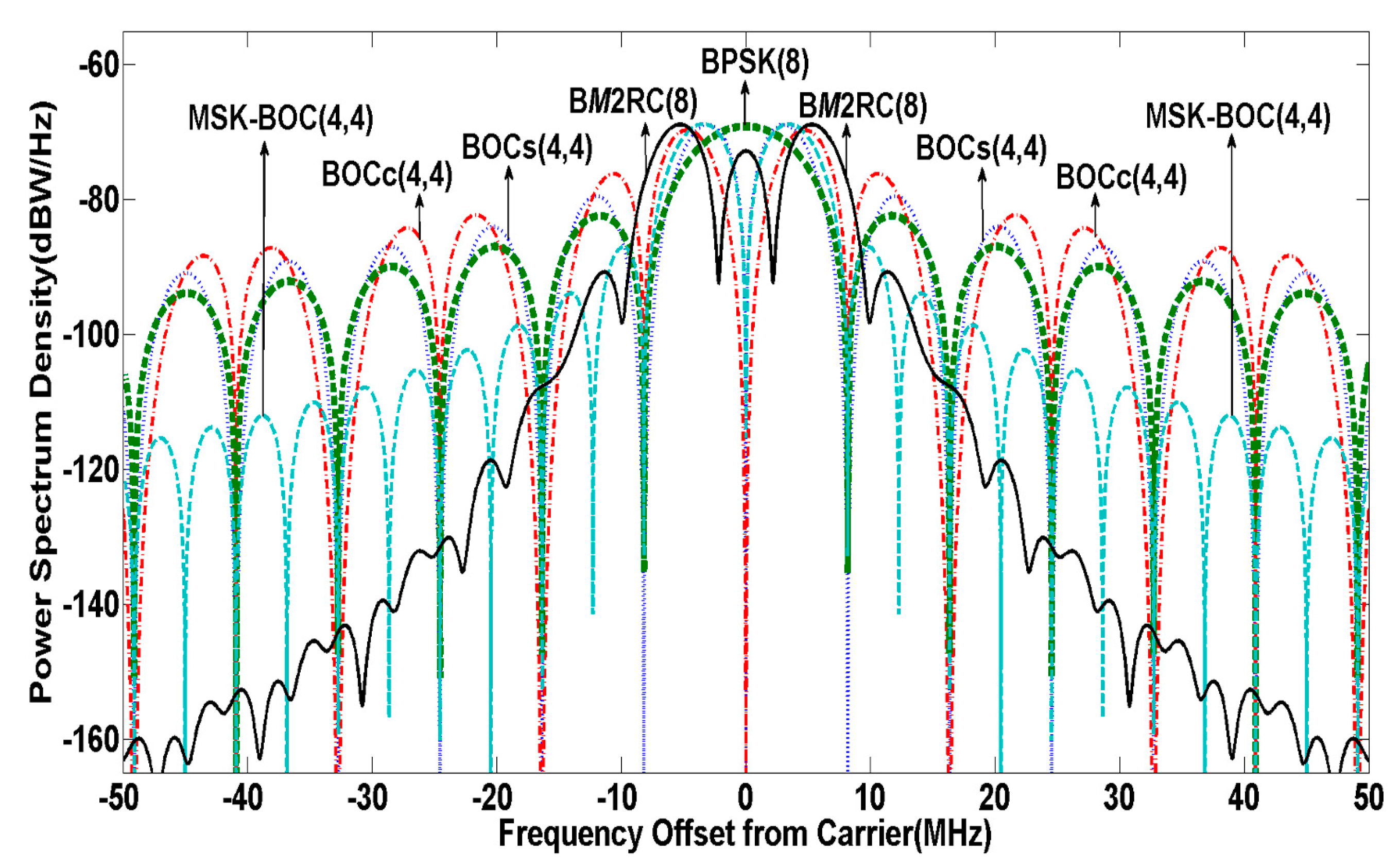
The cos-phase BOCc(4,4), sin-phase BOCs(4,4), MSK-BOC(4,4) [25] and BPSK(8) have been presented as candidates for the future Compass system in the S band [26]. The normalized (unit power over infinite transmission bandwidth) PSD of the above signals as well as BM2RC(8) are shown in Figure 3. Compared with other candidates, the proposed BM2RC(8) reveals a stronger spectrum roll-off in the side lobes, and performs even 35 dB lower than MSK-BOC(4,4) at ±30 MHz while still maintaining the characteristic of spectrum splitting.
Figure 3.
PSD of candidate signals in S band.

4.2. Performance Analysis
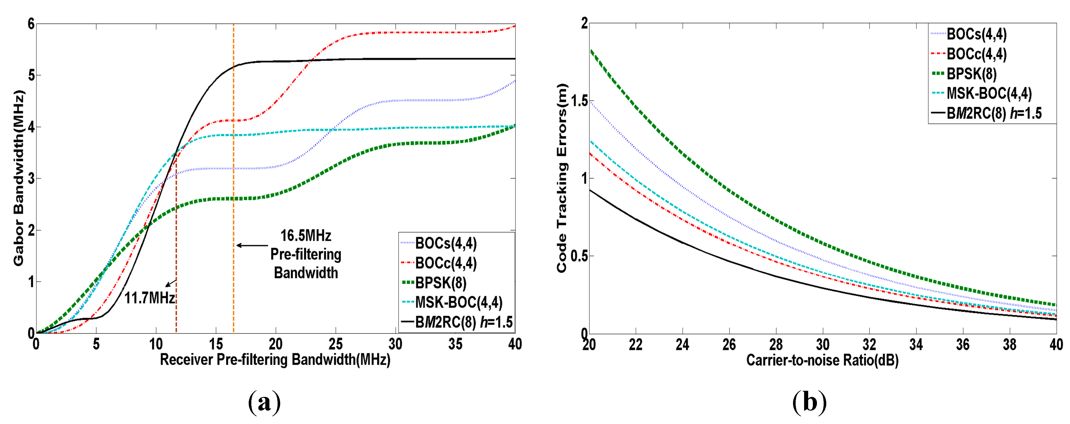
Figure 4 shows the Gabor bandwidth and code tracking error curves of the above signals under the assumption that the receiver pre-filtering bandwidth is equal to 16.5 MHz, tracking loop bandwidth is 1Hz and the correlation time spacing between the early and late reference signals is 0.1 chip. As we see from Figure 4a, the Gabor bandwidth of BM2RC(8) is approaching its maximum at around 16.5 MHz and greater than other modulations when approximately exceeds 11.7 MHz.
Figure 4.
(a) Gabor bandwidth of modulation candidates for S band; (b) Code tracking errors of modulation candidates for S band.
Figure 4.
(a) Gabor bandwidth of modulation candidates for S band; (b) Code tracking errors of modulation candidates for S band.

Meanwhile, the BM2RC(8) gives the minimum code tracking error among the analyzed signals as seen in Figure 4b. Therefore, the BM2RC(8) indicates a better code tracking performance than other candidates for 16.5 MHz of S band.
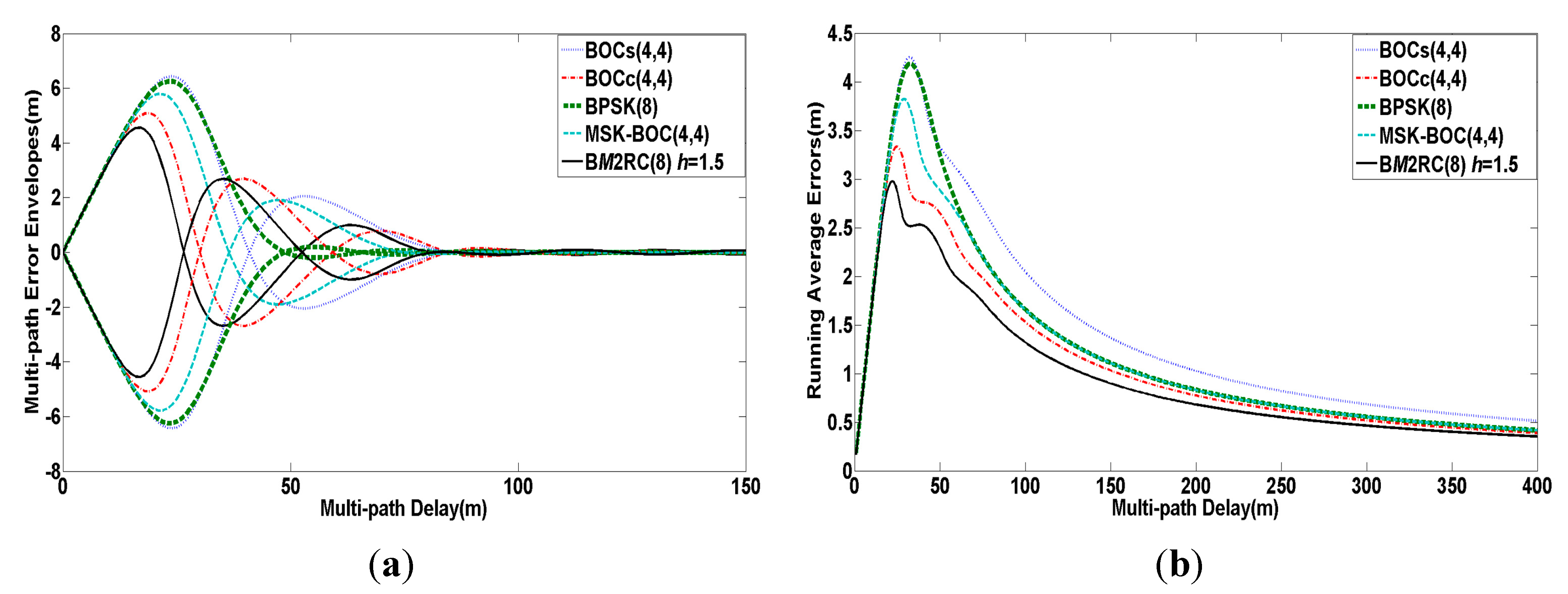
Figure 5.
(a) Multi-path error envelopes of modulation candidates for S band; (b) Average multi-path errors of modulation candidates for S band.
Figure 5.
(a) Multi-path error envelopes of modulation candidates for S band; (b) Average multi-path errors of modulation candidates for S band.

An analysis of multi-path resistance performance for S band signals is estimated by multi-path error envelopes and running average multi-path errors in Figure 5, where MDR is fixed at −6 dB and all other parameters are the same as the previous simulation. As seen in Figure 5, the minimum quantity of running average errors can be provided by BM2RC(8) when the multi-path delay is changed from 0 to 400 m, while it maintains the lowest multi-path error envelope amplitude when the multi-path delay is in the range of [0, 25 m]. We are able to deduce that BM2RC(8) achieves the best multi-path mitigation performance among the above modulations as a result of cutting down the side lobe amplitude to a large extent.
The anti-jamming performance in terms of and for the demodulation process, and and for the code tracking process are calculated in Table 1, where and are set as 16.5 MHz and 50 bps, respectively. Note that the differences among various signals are very slight and even less than 1.3 dB in each anti-jamming merit factor, thus they have similar or comparable anti-jamming ability performance.

| Merit Factors | BM2RC(8) | BOCs(4,4) | BOCc(4,4) | BPSK(8) | MSK-BOC(4,4) |
|---|---|---|---|---|---|
| 70.2910 | 70.7160 | 71.0772 | 72.8167 | 70.5057 | |
| 68.0721 | 67.8803 | 67.8264 | 69.1297 | 68.3023 | |
| 53.5508 | 53.9370 | 55.3525 | 53.9137 | 53.1460 | |
| 51.8673 | 51.9276 | 52.6869 | 52.1400 | 51.7845 |
BPSK(1), BPSK(4), BPSK(8) and BOCc(1,1) have been investigated as possible signals in the S band for the Galileo system centered on a carrier frequency close to 2491 MHz with a 16.5 MHz receiver pre-filter [3,27]. The compatibility between the candidates in the future Compass system, including BM2RC(8) and the Galileo candidates is shown in Table 2. We can observe that the spectral separation degree of BM2RC(8) with BOCc(1,1), BPSK(4), and BPSK(8) is remarkably superior to the others, except for BOCc(4,4), because it contains less low frequency components within the receiver bandwidth that is likely to result in relatively low spectrum efficiency or high spectrum leakage. The compatibility between BM2RC(8) and BPSK(1) is a bit worse than some of the candidates, yet it is still acceptable.
| SSC | BM2RC(8) | BOCs(4,4) | BOCc(4,4) | BPSK(8) | MSK-BOC(4,4) |
|---|---|---|---|---|---|
| BOCc(1,1) | −75.7768 | −72.9434 | −79.0989 | −70.1492 | −73.3354 |
| BPSK(1) | −73.2353 | −79.9343 | −86.0651 | −69.3153 | −80.3243 |
| BPSK(4) | −74.9872 | −73.9122 | −80.0727 | −69.9253 | −74.3046 |
| BPSK(8) | −74.3592 | −72.1678 | −75.2494 | −70.9034 | −72.0851 |
5. Performance Evaluation for C Band Signals
5.1. PSD of C Band Signals
The ITU clearly stipulates that the future C band signals can’t interfere with the normal radio astronomy services (RA, 4990–5000 MHz) and microwave landing system (MLS, 5030–5150 MHz) [4,13]. To meet the strict compatibility condition constraints of the C band, the PSD of modulated signals should have the following characteristics: (1) the majority of power should be concentrated into the main lobe; (2) a stronger spectrum roll-off in side lobes should be provided in order to significantly cut down spectrum leakage or interference to RA and MLS.
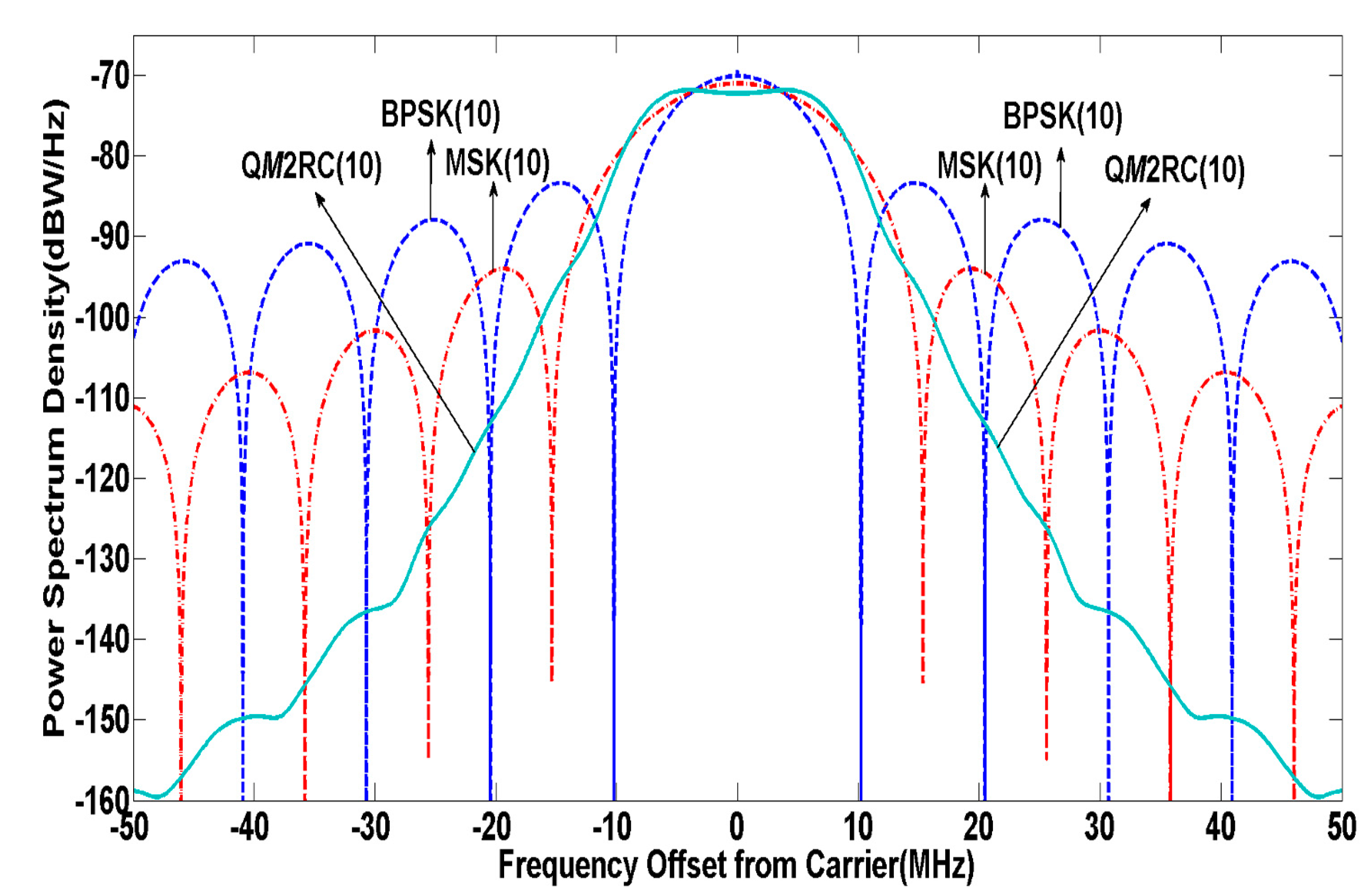
To make a fair analysis, this paper compares BPSK(10), a Galileo C band candidate (MSK(10)) [13] and QM2RC(10) with similar spectral occupancy within the 20 MHz bandwidth of the C band. The normalized PSD of such signals are shown in Figure 6.
Figure 6.
PSD of modulation candidates in C band.

It is shown that the proposed QM2RC(10) can centralize most of power into the main lobe while effectively inhibiting the re-growth of spectrum side lobes compared to other competitors. In view of the stringent compatibility requirements for RA and MLS, without strong output filtering, it is impossible to limit the emissions for any signal to the level required for RA and MLS [4]. Thus, from the C band signal design point of view, the main factor to be addressed is to limit the out-of-band (OOB) emission power based on the fact that a signal with relatively low OOB emission power could significantly mitigate signal distortion caused by non-ideal filter characteristics and degrade noise level to meet strict RA and MLS constraints while also contributing to reducing design complexity and cost of filters on satellites. Table 3 assesses and compares the out-of-band loss within the 20 MHz bandwidth for C band navigation and the OOB emission power of proposed C band candidate signals at RA and MLS services, where a quantity called out-of-band loss is defined as:
| Signal | OOB Emission Power in 4990–5000 MHz band (RA) (dBc) | OOB Emission Power in 5030–5150 MHz Band (MLS) (dBc) | Out-of-Band Loss in 5010–5030 MHz for C Band Navigation (dB) |
|---|---|---|---|
| QM2RC(10) | −49.9821 | −20.4880 | 0.0783 |
| BPSK(10) | −20.8451 | −13.5014 | 0.4428 |
| MSK(10) | −29.9547 | −17.6705 | 0.1512 |
As shown in Table 3, the out-of-band losses for the QM2RC(10) signal within the 20 MHz bandwidth are separately 0.3645 dB and 0.0729 dB lower with respect to BPSK(10) and MSK(10). Besides, the OOB emission power of QM2RC(10) in the RA and MLS band are −49.9821 dBc and −20.4880 dBc, which are even 20.0274 dBc and 2.8175 dBc lower than those of the MSK signal. Due to the high spectral efficiency and relatively low OOB emission power of the QM2RC signal, the spectral separation of C band signals with RA and MLS services can be improved significantly.
5.2. Performance Analysis
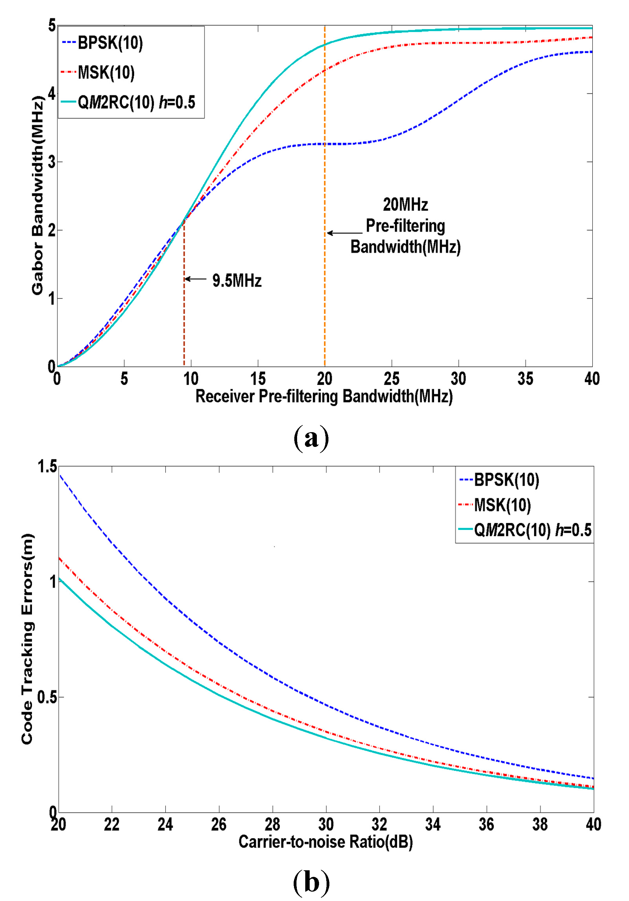
The Gabor bandwidth and code tracking errors of the abovementioned signals are shown in Figure 7, where is 20 MHz. It is obvious that the Gabor bandwidth of QM2RC(10) is very close to that of the others below 9.5 MHz pre-filtering bandwidth, while the Gabor bandwidth of QM2RC(10) appears to outperform the others and finally tends to converge to a value when is higher than 9.5 MHz. In addition, it is also observed from Figure 7b that the proposed QM2RC(10) signal can offer superior tracking accuracy performance compared to other candidates at around 20 MHz for C band navigation service.
Figure 7.
(a) Gabor bandwidth of modulation candidates for C band; (b) Code tracking errors of modulation candidates for C band.
Figure 7.
(a) Gabor bandwidth of modulation candidates for C band; (b) Code tracking errors of modulation candidates for C band.

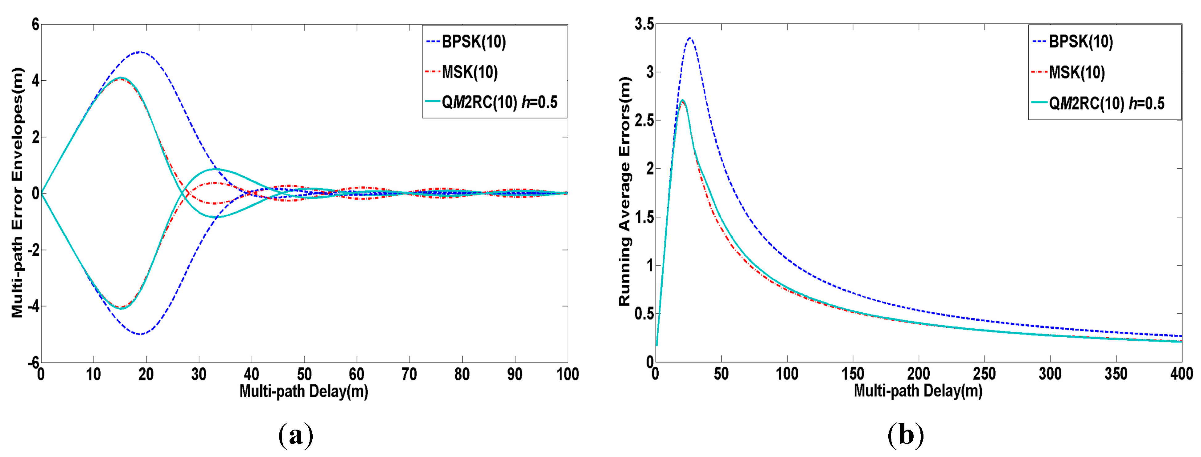
Figure 8 shows the comparison of multi-path mitigation for the three candidate signals in the C band with the same parameters as the former simulation. As seen from the Figure 8, the QM2RC(10) signal has almost equivalent performance to MSK(10) in the aspects of multi-path error envelopes and running average errors, and both of them are superior to BPSK(10).
Figure 8.
(a) Multi-path error envelopes of modulation candidates for C band; (b) Average multi-path errors of modulation candidates for C band.
Figure 8.
(a) Multi-path error envelopes of modulation candidates for C band; (b) Average multi-path errors of modulation candidates for C band.

Table 4 lists the anti-jamming merit factors of C band signals with 20 MHz pre-filtering bandwidth and 50 bps message rate. In the and aspects the QM2RC(10) signal only behaves approximately 0.8 dB worse than MSK(10), while it reveals the best and performance. As a whole, the QM2RC(10) almost shows similar or comparable anti-jamming performance as other candidates.
| Merit Factors | QM2RC(10) | BPSK(10) | MSK(10) |
|---|---|---|---|
| 73.4678 | 73.7855 | 74.2665 | |
| 70.2342 | 70.0984 | 70.9042 | |
| 55.5892 | 54.8792 | 55.4381 | |
| 54.8397 | 52.1400 | 54.0212 |
It is assumed that the BPSK(10), MSK(10) and QM2RC(10) signals centered at the same carrier frequency close to 5020 MHz are broadcast as C band signals. A receiver pre-filtering bandwidth of 20 MHz is used. Table 5 calculates the SSC of the above signals. In terms of self-SSC, the QM2RC(10) is 0.15 dB and 0.71 dB lower than MSK(10) and BPSK(10), respectively, and far better than the minimum shift keying-binary coded signal (MSK-BCS) [7,28], whose self-SSC is −67.2531 dB in the C band [7]. By the above analysis, the QM2RC(10) has a better compatibility performance than the others.
| SSC | QM2RC(10) | BPSK(10) | MSK(10) |
|---|---|---|---|
| QM2RC(10) | −72.5789 | −72.6223 | −72.6020 |
| BPSK(10) | −72.6223 | −71.8689 | −72.2611 |
| MSK(10) | −72.6020 | −72.2611 | −72.4278 |
6. Conclusions
In this paper, we introduced a universal modulation scheme based on the CPM family for multi-band combined navigation. Two specific CPM signals, namely BM2RC(8) and QM2RC(10), are proposed as modulation solutions in the S and C bands, respectively. Theoretical analysis and simulation results show that the proposed modulation schemes can not only meet well the requirement of compatibility in the S and C bands and reduce the user terminal complexity in the multi-band combined navigation mode, but also offer better performance in the aspects of tracking accuracy, multi-path mitigation and anti-jamming compared to potential candidates such as BPSK, BOC, MSK, MSK-BOC, etc. Besides, the modulation schemes also provide new ideas and feasibility demonstration for signal design of multi-band combined navigation satellite systems.
Acknowledgments
The authors would like to thank the reviewers for their beneficial comments and suggestions. This work was supported by the National Natural Science Foundation of China (Grant No. 61403093), Science Foundation of Heilongjiang Province of China for Returned Scholars (Grant No. LC2013C22), the Assisted Project by Heilongjiang Province of China Postdoctoral Funds for Scientific Research Initiation (Grant No. LBH-Q14048) and China Fundamental Research Funds for Central Universities (Grant No. HEUCF1508).
Author Contributions
The work presented in this paper was carried out in collaboration with all authors. Rui Xue and Danfeng Zhao provided the initial ideas and concept; Yanbo Sun implemented the software and carried out the experimental validation; Yanbo Sun and Rui Xue wrote the main manuscript; Danfeng Zhao critically reviewed the paper.
Conflicts of Interest
The authors declare no conflict of interest.
References
- Liu, X.; Liang, M.; Morton, Y.; Closas, P.; Zhang, T.; Hong, Z. Performance evaluation of MSK and OFDM modulations for future GNSS signals. GPS Solut. 2014, 18, 163–175. [Google Scholar] [CrossRef]
- Irsigler, M.; Hein, G.W.; Schmitz-Peiffer, A. Use of C-Band frequencies for satellite navigation: Benefits and drawbacks. GPS Solut. 2004, 8, 119–139. [Google Scholar] [CrossRef]
- Mateu, I.; Paonni, M.; Issler, J.L.; Hein, G.W. A search for spectrum: GNSS signals in S-Band part 1. Inside GNSS 2010, 5, 65–71. [Google Scholar]
- Colzi, E.; Lopez-Risueño, G.; Samson, J.; Angeletti, P.; Crisci, M.; De Gaudenzi, R.; Gerner, J.L. Assessment of the Feasibility of GNSS in C-Band. In Proceedings of the International Communications Satellite Systems Conference, San Diegom, CA, USA, 10–12 June 2008; pp. 1–15.
- Hein, G.W.; Irsigler, M.; Avila-rodriguez, J.A.; Wallner, S.; Pany, T.; Eissfeller, B.; Hartl, P. Envisioning a future GNSS system of systems part 3. Inside GNSS 2007, 6, 64–73. [Google Scholar]
- Issler, J.L.; Eissfeller, B. Toward centimetric positioning thanks to L-and S-Band GNSS and to meta-GNSS signals. In Proceedings of the 2010 5th ESA Workshop on Satellite Navigation Technologies and European Workshop on GNSS Signals and Signal Processing, Toulouse, France, 8–10 December 2010; pp. 1–8.
- Liu, M.; Zhan, X.; Li, W.; Chen, M. MSK-BCS modulation for GNSS radio frequency compatibility in C Band. J. Netw. 2014, 9, 2713–2720. [Google Scholar] [CrossRef]
- Liu, M.; Zhan, X.; Li, W.; Chen, M. A compatibility analysis between GNSS and radio astronomy/microwave landing system in C band. J. Aeronaut. Astronaut. Aviat. 2014, 46, 102–107. [Google Scholar]
- Amat, A.G.; Nour, C.A.; Douillard, C. Serially concatenated continuous phase modulation for satellite communications. IEEE Trans. Wirel. Commun. 2009, 8, 3260–3269. [Google Scholar]
- Baroni, R.; Lombardo, F.; Suffritti, R.; Candreva, E.A.; Vanelli-Coralli, A.; Corazza, G.E.; Colavolpe, G.; Gallinaro, G.; Alagha, N. Performance analysis of a mesh satellite system based on linear and continuous phase modulations. In Proceedings of 2012 IEEE International Conference on Communications, Ottawa, ON, Canada, 10–15 June 2012; pp. 3255–3259.
- Emmanuele, A.; Zanier, F.; Boccolini, G.; Luise, M. Spread-spectrum continuous-phase-modulated signals for satellite navigation. IEEE Trans. Aerosp. Electron. Syst. 2012, 48, 3234–3249. [Google Scholar] [CrossRef]
- Thoelert, S.; Montenbruck, O.; Meurer, M. IRNSS-1A: Signal and clock characterization of the Indian regional navigation system. GPS Solut. 2014, 18, 147–152. [Google Scholar] [CrossRef]
- Avila-Rodriguez, J.-A.; Wallner, S.; Won, J.-H.; Eissfeller, B.; Schmitz-Peiffer, A.; Floch, J.-J.; Colzi, E.; Gerner, J.-L. Study on a Galileo signal and service plan for C-band. In Proceedings of International Technical Meeting of the Satellite Division of The Institute of Navigation, Savannah, GA, USA, 16–19 September 2008; pp. 2515–2529.
- Aulin, T.; Sundberg, C.E. Continuous phase modulation-part I: Full response signaling. IEEE Trans. Commun. 1981, 29, 196–209. [Google Scholar] [CrossRef]
- Aulin, T.; Rydbeck, N.; Sundberg, C.E. Continuous phase modulation-part II: Partial response signaling. IEEE Trans. Commun. 1981, 29, 210–225. [Google Scholar] [CrossRef]
- Rimoldi, B. A decomposition approach to CPM. IEEE Trans. Inf. Theory 1988, 34, 260–270. [Google Scholar] [CrossRef]
- Anderson, J.B.; Aulin, T.; Sundberg, C.E. Digital Phase Modulation; Plenum Press: New York, NY, USA, 1986; pp. 149–153. [Google Scholar]
- Betz, J.W.; Kolodziejski, K.R. Generalized theory of code tracking with an early-late discriminator part I: Lower bound and coherent processing. IEEE Trans. Aerosp. Electron. Syst. 2009, 45, 1538–1556. [Google Scholar] [CrossRef]
- Sahmoudi, M.; Landry, R.J. Multipath mitigation techniques using maximum-likelihood principle. Inside GNSS 2008, 8, 24–29. [Google Scholar]
- Kaplan, E.D.; Hegarty, C.J. Understanding GPS: Principle and Application, 2nd ed.; Artech House: Boston, MA, USA, 2006; pp. 279–295. [Google Scholar]
- Betz, J.W. Effect of Partial-Band interference on receiver estimation of C/N0: Theory. In Proceedings of the Institute of Navigation, Long Beach, CA, USA, 22–24 January 2001; pp. 817–828.
- Betz, J.W.; Goldstein, D.B. Candidate designs for an additional civil signal in GPS spectral bands. In Proceedings of the National Technical Meeting-Institute of Navigation, San Diego, CA, USA, 28–30 January 2002; pp. 622–631.
- Betz, J.W.; Titus, B.M. Intersystem and intrasystem interference with signal imperfections. In Proceedings of the Position Location and Navigation Symposium, Fort Worth, TX, USA, 26–29 April 2004; pp. 558–565.
- Soualle, F.; Burger, T. Radio frequency compatibility criterion for code tracking performance. In Proceedings of the International Technical Meeting of the Satellite Division of The Institute of Navigation, Fort Worth, TX, USA, 25–28 September 2007; pp. 1201–1210.
- Wang, F.; Zeng, D.; Li, R. Study on MSK Modulation for S-band. In Proceedings of 2013 China Satellite Navigation Conference, Wuhan, China, 15–17 May 2013; pp. 61–69.
- Qin, P. The research of the signal in the S frequency band. In Proceedings of 2013 China Satellite Navigation Conference, Wuhan, China, 15–17 May 2013; pp. 1–5.
- Mateu, I.; Boulanger, C.; Issler, J.-L.; Ries, L.; Avila-Rodriguez, J.-A.; Wallner, S.; Kraus, T.; Eissfeller, B.; Mulassano, P.; Germaine, S.; et al. Exploration of possible GNSS signals in S-band. In Proceedings of the International Technical Meeting of The Satellite Division of the Institute of Navigation, Savannah, GA, USA, 22–25 September 2009; pp. 1573–1587.
- Liu, W.; Du, G.; Zhan, X.; Zhai, C. MSK-BCS coded symbol modulations for global navigation satellite systems. IEICE Electron. Express 2010, 7, 421–427. [Google Scholar] [CrossRef]
© 2015 by the authors; licensee MDPI, Basel, Switzerland. This article is an open access article distributed under the terms and conditions of the Creative Commons Attribution license (http://creativecommons.org/licenses/by/4.0/).
Share and Cite
MDPI and ACS Style
Xue, R.; Sun, Y.; Zhao, D. CPM Signals for Satellite Navigation in the S and C Bands. Sensors 2015, 15, 13184-13200. https://doi.org/10.3390/s150613184
AMA Style
Xue R, Sun Y, Zhao D. CPM Signals for Satellite Navigation in the S and C Bands. Sensors. 2015; 15(6):13184-13200. https://doi.org/10.3390/s150613184
Chicago/Turabian StyleXue, Rui, Yanbo Sun, and Danfeng Zhao. 2015. "CPM Signals for Satellite Navigation in the S and C Bands" Sensors 15, no. 6: 13184-13200. https://doi.org/10.3390/s150613184