Prospects of Photonic Crystal Fiber as Physical Sensor: An Overview

1
Indian Institute of Technology (Indian School of Mines), Department of Applied Physics, Fiber Optics Lab, Dhanbad 826004, India
2
Fiber Optics and Photonics Division, CSIR-Central Glass and Ceramic Research Institute, CSIR, Kolkata 700032, India
*
Authors to whom correspondence should be addressed.
Sensors 2019, 19(3), 464; https://doi.org/10.3390/s19030464
Submission received: 27 November 2018
/
Revised: 11 December 2018
/
Accepted: 11 December 2018
/
Published: 23 January 2019
(This article belongs to the Special Issue Optical Sensors Using Microstructured and Photonics Crystal Fibers)
Abstract
:Photonic crystal fiber sensors have potential application in environmental monitoring, industry, biomedicine, food preservation, and many more. These sensors work based on advanced and flexible phototonic crystal fiber (PCF) structures, controlled light propagation for the measurement of amplitude, phase, polarization and wavelength of spectrum, and PCF-incorporated interferometry techniques. In this article various PCF-based physical sensors are summarized with the advancement of time based on reported works. Some physical PCF sensors are discussed based on solid core as well as hollow core structures, dual core fibers, liquid infiltrated structures, metal coated fibers, grating incorporated fibers. With the advancement of sensing technology the possibilities of temperature, pressure, strain, twist, curvature, electromagnetic field, and refractive index sensing are discussed. Also, limitations as well as possible solutions and future hopes are outlined.
1. Introduction
PCF was invented by invented by Russell and his colleagues at the end of 20th century [1]. From its invention PCF is showing its potential not only in low loss communication but also in many versatile and improved applications-sensing is one of them. Investigation of different physical parameters using photonic crystal fiber (PCF) is an integrative branch of optics as well as engineering. It successfully integrates fiber optics, structural engineering, electromagnetism, laser optics, the infiltration technique, optoelectronics, microelectronics, and material science. Photonics crystal fiber sensors are advantageous over other electrical and optical fiber sensing system in many aspects.
PCF has an advantageous geometry over standard optical fiber. Generally, PCF has either a hollow core or a solid core around which air holes are distributed in different patterns. Light is guided by the distribution of these air holes. Also, propagation of light can be manipulated by changing the distribution of air holes as well as with the environmental change [2,3,4]. This unique nature of PCF is drawing a lot of attention for its sensing applications from last two decades. PCF-based sensors became the focus of many research groups due to their high sensitivity, flexibility, small size, robustness, and that they can be used in many unfavorable situations. The small physical dimensions of PCF-based sensing probes make them suitable for attaching or inserting in a system. These sensing probes can be connected with the control system without the use of any wire. They can be used in a hazardous and noisy environment or high temperature, high voltage, high electromagnetic field, and explosive environments even for the purpose of remote sensing.
Measurement of different physical parameters like, temperature, pressure, strain, twist or torsion, curvature or bend, and electromagnetic field is necessary for regular application, shown in Figure 1. In this article we tried to present an updated and compact description of PCF sensors applied or proposed for physical parameter sensing. It consists theoretical background of PCF, its wide range of applications for physical parameter measurement, current technologies as well as short comes and finally ended with concluding discussion.
2. Theoretical Framework of PCF
For a conventional optical fiber both the core and cladding both are solid. Generally cladding is pure silica and the core is doped glass-having a relatively high refractive index in comparison to cladding [5]. So, there is a positive refractive index difference between core and cladding. But in the case of PCF this refractive index difference is imposed by placing air holes in cladding. These air holes run throughout the length of the fiber and took an important role in guiding light through the core. Depending on the core nature PCF can be divided in two broad categories: solid core PCF and hollow core PCF. If the core is solid then it is solid core PCF (Figure 2). It has a positive refractive index difference between the core and cladding and it works based on the total internal reflection (TIR) phenomenon [2,6]. For hollow core PCF (Figure 3), the core is made of air and it has a negative refractive index difference between the core and cladding. It works based on photonic bad gap guiding mechanism [2,7].
PCF has many attractive properties compared to standard optical fibers like, highly birefringent [3,8], very low loss [9,10], endless single-mode propagation through a long wavelength range [1,11,12], highly nonlinear [13,14], dispersion tailoring [15,16], and large mode area [17,18]. These unique optical properties encourage researchers to use PCF not only in the field of communication [14,19,20,21] but also in spectroscopy [22], supercontinuum generation [23], nonlinear applications [24], Raman fiber laser [25,26], sensing [27], etc. Using the holey nature of PCF many sensors are proposed as well as fabricated with very high sensitivity [28,29]. PCF-based advanced physical sensors will be discussed in the following sections.
For an optical fiber, V-number and Numerical aperture (NA) are two important optical parameters. Endlessly single-mode (ESM) propagation of a PCF is decided by its V-number. Through a long wavelength range, the single-mode propagation capability of a PCF due to its exceptional cladding microstructure is defined as endlessly single-mode propagation. The V-number of a PCF can be calculated according to Mortensen et al. [11] using the following formula,
where Λ is pitch of PCF. From Equation (1) it can be observed that endlessly single-mode operation of a PCF depends on both its parameter and propagating wavelength. For PCF, the single-mode cut-off criteria is VPCF < π. Here, neff is the effective refractive index of guided-mode of PCF and ncore is refractive index of the core. neff can be expressed as neff = β/k0—where β is the propagation constant and k0 is free space propagation constant. Also k0 can be expressed as k0 = 2π/λ, where λ is the propagating wavelength [30].
Light gathering potential of an optical fiber is represent by numerical aperture. It is a dimensionless quantity. Large NA indicates more light gathering capability of a fiber. For PCF, NA can be calculated using the following formula [30],
From the very start, different kinds of PCFs are designed, analyzed by using commercial software as well as fabricated. Mostly, these analyzed works are based on either the finite element method or the finite difference time domain method. In both methods the whole structure is meshed in triangular pieces then the electromagnetic equations are applied in each section and the light guiding nature is studied. These techniques are very popular in computational electromagnetism [31,32,33]. They reduce losses during fabrication and enhance accuracy.
Many sensors are reported based on dual core PCF. Dual core PCF works based on mode coupling theory due to the coupling that four supermodes (x even, y even, x odd, and y odd modes) generate. For one coupling length power transfer completely from one core to another. At output optical power intensity can be calculated as
Here, Δni with i = x,y is effective refractive index difference of x polarized even-odd mode and y polarized even-odd mode. Output intensity curve is sinusoidal in nature. Sensitivity of a dual core PCF consisting probe can be calculated from the output transmission peak shift with changing environment [34,35].
3. Overview of PCF Physical Sensors
PCF-based sensors are advantageous over standard optical fiber sensors in many aspects. They not only have great design flexibility but also their holey internal structure can be filled with analyte so that a controlled interaction can take place between propagating light and the analyte sample [36]. This greatly enhances the sensitivity of fiber optic sensors as well as opens up a new direction for making advanced portable sensors. PCF sensors have a wide range of applications. Measurement of different physical parameters like temperature, pressure, strain, twist, torsion, curvature, bend, and electromagnetic field are a few of them. Observation as well as control of these parameters are really important in many daily life applications including civil structural health monitoring [37]. PCF-based physical sensors are gaining a lot of attention due to their in situ and remote sensing capabilities; immunity from the hazardous environments of high electromagnetic field and high voltage; and biomedical sensing capability [37,38]. At the very beginning main focus was on fabricating PCF-based sensors using different interferometry techniques. However, with time the focus has shifted toward the design and fabrication of new PCF structures with advanced optical properties and their application for making sensors. Evolution of different physical sensors are discussed in the following sections.
3.1. Temperature Sensors
Temperature measurement is an important physical parameter for all fields of technical activities, industrial stages of production and maintenance and also in medical treatments. The invention of fiber optic sensors for temperature measurement was a great breakthrough representing a viable alternative to the use of electronic sensors. These sensors can be made with multimode fiber (MMF), single-mode fiber (SMF), and enhances the sensitivity of measurement using a laser source with optoelectronics. The most practical advantage is to use fiber-based temperature sensors in the field of applications where electromagnetic interference (EMI) and RF are vital obstructions to the use of electronic sensors. PCF-based sensors are also useful in aerospace, defense, the chemical industry, semiconductor industry, civil engineering applications, turbine areas, and many more. In the field of these sensors, Zhu et al. fabricated, as well as demonstrated [39], strain-insensitive and high-temperature long-period gratings sensors inscribed in solid core PCF having sensitivity of 10.9 pm/°C from 24 °C to 992 °C illuminated by CO2 laser at 1299.59 nm wavelength. A hexagonal solid core PCF sensor was reported [40] with sensitivity 7 nm/°C when air holes were filled with 1550 nm liquid crystal (Figure 4) for the measurement of temperature and electric fields. A layer-by-layer quantum dot nanocoatings on the inner holes of PCF (LMA-20) spliced with MMF is experimentally demonstrated [41] in the temperature range of 40 °C to 70 °C with wavelength sensitivity 0.1451 nm/°C (Figure 5). A 7-cell HCPCF sensor spliced with a SMF was reported previously [28] with sensitivity −7.1 pm/°C (Figure 6). Another selectively filled polarization-maintaining PCF (PMPCF) temperature sensor based on the Sagnac interferometer was reported [42], in which L1 is the infiltration length and L is the total length of PM-PCF inside the fiber loop as shown in Figure 7. It has sensitivity 2.58 nm/°C for the 11.7 cm-long fiber as measured from transmission wavelength shift.
A relatively new structured PCF temperature sensor [43] was demonstrated when a standard Si wafers was attached to the facet of a standard single-mode optical fiber. It acts as a tip sensor with a sensitivity of 0.11 nm/°C in the 100 °C to 700 °C temperature range. Another temperature sensor was fabricated [44] based on Mach–Zehnder interference and dual core PCF with selectively polymer-filled air holes with high sensitivity 1.595 nm/°C (Figure 8). A surface plasmon resonance based PCF temperature sensor with nanoscale gold coating of the central air hole was reported [31] with sensitivity −2.15 nm/°C (Figure 9). Fully and partially ethanol-filled photonic bandgap fibers spliced between standard SMF was reported [45] having temperature sensitivity −292 pm/°C and −120 pm/°C for fully and partially filled ethanol, respectively. Few more temperature sensors are presented in Table 1.
3.2. Pressure Sensors
Pressure is an important physical quantity when observing many environmental phenomena in precision application areas as well as monitoring many industrial processes in spite of the harsh environment. Due to the good compatibility of fiber pressure sensors with human and other animal bodies they can be used in medical diagnosis purpose also. PCF-based pressure sensors can be used in measuring human body fluid pressure. These sensors are also suitable in measuring temperature and pressure under water. In 2005, a polarization-maintaining PCF PM-1550-01-based pressure sensor was developed [56] by Blaze photonics (Figure 10). A hydrostatic pressure sensor was reported [57] with highly birefringent PCF and sensitivity −10 rad/MPa.m at 1.44 μm wavelength (Figure 11). Then a compact pressure sensor was developed [58] using Sagnac interference with a polarization-maintaining PCF with sensitivity 3.42 nm/MPa for a 58.4 cm long fiber (Figure 12). Another highly birefringent hydrostatic pressure sensor was demonstrated [59] theoretically as well as experimentally having sensitivity more than −43 rad/MPa.m at 1.55 μm wavelength (Figure 13). A sensor was reported [60] using a Fabry–Pérot cavity in which a microstructure fiber is spliced between SMF and hollow-core fiber with pressure sensitivity −4.68 × 10⁻⁵ nm/psi (Figure 14). A pore water pressure sensor was reported [32] with a six-hole suspended-core PM-PCF-based Sagnac interferometer having sensitivity 254.75 kPa/nm for a 100 cm long fiber (Figure 15). Excluding the sensors listed above a few more pressure sensors are presented in Table 2.
3.3. Strain Sensor
Strain measurement is a necessary requirement in industrial application and precision control system. Fiber optics-based strain sensors can be used in earthquake damage detection, in defense applications, monitoring telecommunication cables during temperature variation, process control, load control on important bridges & structures, fire detection, etc. These sensors have important applications in civil engineering: in bridge monitoring, welding residual stresses monitoring, observation of old heritage buildings, pipeline monitoring, and other structural health monitoring. An endlessly single-mode PCF-based cable consisting a long period grating has been fabricated [66] using a spatially periodic electric arc discharge technique. It has strain sensitivity −2.0 pm/µε. Using a highly birefringent PCF loop mirror coated with acrylate material a strain sensor was reported [67] with enhanced sensitivity of 1.21 pm/µε. The length of the sensing head for this sensor was 380 mm. A hollow-core photonic band gap fiber based Fabry–Pérot (FP) interferometric strain sensor was reported [68] having FP cavity in the order of millimeters and fabricated by the simple techniques of cleaving and fusion splicing. The sensitivity of the sensor is 1.55 pm/µε at the wavelength of 1550 nm and suitable for a wide range of applications.
A low loss PM-PCF-based birefringent interferometer strain sensor was reported [69] with strain sensitivity 1.3 pm/με in a strain range from 0 με to 1600 με (Figure 16). A F-P cavity having length 207 μm was fabricated by splicing a hollow-core ring PCF between two standard SMF and using this a strain sensor was fabricated [70] with sensitivity 15.4 pm/µε for a FP cavity of 13 µm length (Figure 17). A strain sensor was reported [71] using a dual-core PCF-based Mach–Zehnder interferometer having sensitivity −0.31 pm/µε within a range 0 με to 4000 µε (Figure 18). A multi components interferometer based on partially filled dual-core PCF was demonstrated [72] in which cladding air holes surrounding of core a were blocked by glue and air holes surrounding of core b were kept open. It has sensitivity −2.08 pm/µε. A few more strain sensors are presented in Table 3.
3.4. Twist or Torsion Sensor
Torsion is an important parameter that has to measure for different civil structure for safety purpose. For immunity against harsh environment, light weight, small size, and high shock survivability are required and these types of sensors are attracting attention due to their suitability for industrial use. A single-mode PCF was demonstrated [79] as a torsion sensor by including stress induced mechanical long-period grating. The sensitivity of this sensor is 0.73 nm/2π. A two-linearly polarized mode operation in a ultrahigh birefringent photonic crystal fiber-based twist sensor was reported [80] having sensitivity of 8.25/°C with resolution ~2.7° for the range 90–270°.
A suspended twin-core fiber based loop mirror configuration was demonstrated [81] as a torsion sensor having sensitivity 5.1 × 10⁻⁴/°C (Figure 19). Another sensor was reported [82] using Hi-Bi PCF-based Sagnac interferometer having sensitivity ~0.06 nm/°C. A torsion sensor was reported [83] using side leakage PCF with sensitivity 0.9354 nm/°C over a range of 0 to 90 in both clock wise and anticlockwise direction. Thereafter, a solid core low birefringence PCF (LMA-10)-based Sagnac interferometer using torsion sensor was proposed [84] with sensitivity 1.00 nm/°C and resolution 0.01°. A three-beam path Mach–Zehnder interferometer was formed [85] by fusion splicing a piece of double ytterbium-doped double-cladding PCF between two segments of SMF to fabricate torsional sensor with sensitivity 0.001 nm/°C (Figure 20).
3.5. Curvature or Bend Sensors
Curvature is also an important parameter in structural health monitoring. Curvature sensors are useful in robot making, in medical tooth root canaling treatment, in artificial organs, etc. In 2001 a two core PCF was used [86] to make a two-beam interferometer to measure its phase change curvature variation and sensitivity 127 rad/rad (Figure 21). A long-period fiber grating incorporated into a holey fiber was reported as a bending sensor considering its axial rotation angle [87]. This sensor shows a shift of the central wavelength into the shorter wavelength for bending curvature higher than 4 m−1 also the bending sensitivity change by rotational orientation (Figure 22). A two-asymmetric hole region consisting of a highly birefringent PCF inserted into a Sagnac interferometer was demonstrated as a curvature sensor [88]. It is able to work in a curvature range of 0.6 to 5 m−1. A curvature sensor was demonstrated [89] with a low-birefringence PCF-based Sagnac loop, consisting of a 40 cm-long PCF having curvature measurement sensitivity of −0.337 nm in the range of 0–9.92 m−1 (Figure 23). A curvature sensor was reported by Hwang et al. [90] using novel PCF of high birefringence based Sagnac interferometer. Its sensitivity depends on the bending direction. Obtained sensitivity is −1.87 nm/m−1 and 1.24 nm/m−1 for parallel and perpendicular bending, respectively, to the large air hole axis near 1480 nm wavelength (Figure 24).
Then a three-coupled core consisting of a PCF-based curvature sensor was reported [91] with a maximum curvature sensitivity of 2.0 dB/m−1 for the curvature range 0 to 2.8 m−1 (Figure 25). A curvature sensor was demonstrated [92] using a tapered PCF collapsed with SMF-based Mach-Zehnder interferometer with sensitivity 8.35 dB/m−1 in between curvature 0.87 and 1.34 m−1 with resolution 0.0012 m−1 (Figure 26). Another curvature sensor was reported [93] with a hollow core PCF-based Sagnac interferometer having sensitivity 0.232 nm/m−1 in the curvature range of 0 to 9.9 m−1. A cladding modes analyzation-based long-period gratings PCF curvature sensor was proposed [94] with sensitivity ~20 nm for 1550 nm wavelength for curvature range 0 to 2 m−1 (Figure 27). A microcavity curvature sensor was manufactured [95] by splicing a hollow core PCF at the end of a SMF. Its maximum sensitivity was found 10.4 dB/m−1 for the curvature range 0 to 1 m−1 with a second taper diameter of 18 μm (Figure 28).
3.6. Electromagnetic Sensors
Electromagnetic field and associated force is one of the fundamental forces of nature. It creates strong and detectable for high electricity consuming objects which is harmful for leaving beings but this field is not detectable by the sense organs. So sensing of this field as well as its current in many cases is an important task. In electric power industry and other places presence of metal may influence the electromagnetic field measurement. So, fiber optics sensors are suitable for the same. Also, the properties of fiber for remote sensing are small size, nonconducting nature, and immunity to electromagnetic interference representing them as a suitable candidate in making electromagnetic sensors based on PCF. Among the various reported electromagnetic sensors some of them are discussed here. At the early stage a solid core PCF filled with liquid crystal (LC) was demonstrated [40] as an electric field sensor based on the orientation of the LC molecules with the changing of an applied electric field. Then moving a few steps forward based on this LC (MDA-05-2782) filling in a PCF (LMA-8) a sensor probe was reported [96] for measuring high electric field intensity with sensitivity ~10.1 dB/kV rms/mm for the electric field intensity range 2.35–4.95 kV rms/mm and resolution ~1 V rms/mm for in-line type transmitted mode (Figure 29). In the same year a magnetic field sensor was demonstrated [97] on a PM-PCF, by filling its cladding air holes with Fe3O4 nanofluid. This sensor has sensitivity 242 pm/mT for the concentration of the fluid 0.6 mg/mL (Figure 30).
Then using hollow core PCF which forms a FP cavity, core of which is filled with water-based CdFe2O4 as the magnetic fluid, a magnetic field sensor was proposed [98] with sensitivity 33 pm/Oe for a very small sensor probe of 200 µm (Figure 31). A glass core PCF-based current sensor using electromagnetic vibration was reported [99] in the same period (Figure 32).
A loss based ferrofluid (EMG905) infiltrated microstructured polymer optical fiber (MPOF) magnetic field sensor was demonstrated [100] which can measure the magnetic field change up to 2000 gauss for the magnetic field perpendicular to the fiber axis. The refractive index of the ferrofluid changes per magnetic field as ~1 × 10⁻³/100 G (Figure 33). A tapered PCF coated with ferrofluid (water-based ferrofluid EMG507, Ferrotec) was reported [101] as a magnetic field sensor. It was made by a tapered PCF spliced between two SMF. It has sensitivity 16.04 pm/G for the magnetic field range 100 to 600 G with resolution 0.62 G (Figure 34). Then a magnetic field sensing probe was proposed [34] which consists of a dual core PCF and both the cores are filled with Fe3O4 magnetic fluid. These two cores behave as two separate wave guides and mode coupling takes place between them. Based on mode coupling different high magnetic field can be identified from spectral shift. This probe has sensitivity 305.8 pm/Oe (Figure 35). Very recently a SPR technique was combined with PCF for the purpose of magnetic field detection in which two parts of gold-layer-filled PCF are joined together to achieve a localized SPR effect [102]. Cladding air holes of the two PCF segments were filled selectively with magnetic fluid and force was applied on one of it (Figure 36). It gives some new way to think about SPR based magnetic field sensors. Recently Yin et al. demonstrated [103] a nanomagnetic fluid filled double clad PCF-based magnetometer which is working on a modal interference mechanism and has a sensitivity 114.5 pm/mT. Also a polarization maintaining PCF incorporated Sagnac interferometer was proposed [104] for magnetic field detection. Water based nanoparticles Fe3O4 are infiltrate into the fiber. Refractive index changing property of magnetic fluid with changing magnetic field is used to study its two dip wavelengths shift with increasing magnetic field. It has sensitivity 384 pm/Oe in the detection range of 410 to 600 Oe. Recently, De et al. proposed a square lattice dual core photonic crystal fiber based magnetic field sensor with sensitivity 799.07 pm/Oe for magnetic field variation form 89.9 Oe to 271.0 Oe [105].
3.7. Refractive Index Sensors
Refractive index is an important basic physical parameter. In situ measurement of it helps to identify a material in many practical fields, like, chemical industry, gas and oil field industry, food processing and quality control industry, to check the adulteration level in liquid, for the identification of biomolecules, etc. At the beginning commercially available LMA PCFs were the main point of interest of many research groups for the development of PCF sensors. In 2005 a LMA-tapered holey fiber containing collapsed air hole refractive index sensor was experimentally demonstrated by Minkovich et al. [106] with a resolution around 1 × 10⁻⁵ for a refractive index higher than 1.44 (Figure 37). A combination of three-hole microstructured optical fiber and Fiber Bragg Grating (FBG) was reported [107] for refractive index sensing. Fiber Bragg grating (FBG) was written in the suspended Ge-doped silica core. It has a resolution of 3 × 10⁻⁵ and 6 × 10⁻⁵ for refractive index 1.33 and 1.40 (Figure 38). In 2007 Sun et al. reported a HC-PCF-based refractive index sensor [108] which works based on photonic band gap principal. It has resolution 2 × 10⁻⁶ RIU in RI range 1.333 to 1.390. Demodulation technique was applied here. At RI 1.35 it shows a blue shift of 110 nm for RI change of 0.02 (Figure 39).
Also different interferometry techniques are combined with PCF to make an advanced sensing system. Jha et al. demonstrated an interferometry based sensing probe in which a LMA PCF spliced between two single-mode fiber [109]. Length of the interferometer was 32–mm. This sensor has a high resolution of 2.9 × 10⁻⁴ in RI range 1.38–1.44. During this period hollow nature of PCF successfully combined with selective infiltration technique to make an improvised PCF sensing probe. Using this technique on a probe was reported [110], in which one air hole of a solid core PCF is filled with liquid. Here a strong field overlap takes place between core mode and mode associated with fluid infiltrated waveguide. Its sensitivity is 30,100 nm/RIU with resolution 4.6 × 10⁻⁷. A dual core PCF works based on mode coupling between two cores. A RI sensing probe was proposed [35] based on a dual core PCF in which central air hole is filled with suspected analyte (Figure 40). It shows sensitivity 7000 nm/RIU for a large RI variation. Sensitivity of PCF-based RI sensors enhanced multiple times when PCF is integrated with surface Plasmon resonance effect. Here, sensitivity can be determined from resonance peak shift. Dash et al. reported a graphene and silver coated birefringent PCF probe having external flow of analyte [111] for RI sensing. It has sensitivity 860 RIU−1 and resolution 4 × 10⁻⁵ RIU (Figure 41). Also, a gold layer coated D-shaped PCF probe was proposed [33] with high average sensitivity 7700 nm/RIU and resolution 1.30 × 10⁻⁵ RIU in refractive index range 1.43–1.46 (Figure 42). Recently, Rifat et al. successfully fabricated [112] a birefringent PCF-based selectively gold layer coated sensing probe (Figure 43) with sensitivity 11,000 nm/RIU for RI variation from 1.33 to 1.42. A few more RI sensors are presented in Table 4.
4. Limitations and Technological Advancement
At the very beginning PCF was applied as a waveguide. Then after nearly four years it started to be used as a sensor. So, PCF sensor technology is now at its infancy stage. In spite of that research progressed very rapidly in this filed due to its versatile and advanced optical properties over conventional optical fiber sensor and commercially available bulk sensors. Throughout this time many PCF sensors have been proposed and fabricated but it cannot be denied that the majority of the designed sensors are still at the proposal stage. At present the light of hope is the drastically developing PCF sensing technology. PCF was stated to be fabricated with a very popular stack and draw technique [2]. With this technique asymmetric, complex, and submicron structure fabrication was almost impossible. Then with time drilling [123], 3D printing [124], sol-gel [125], and extrusion [126] techniques were developed for the fabrication of advanced PCF. Selective infiltration of air holes either with analyte or particles [105,127] and application of noble metal or thin film coating inside air hole or outside of PCF [128,129,130] enhance its sensitivity several times over existing fiber sensors. Capillary force, focused ion beam milled micro channels can be applied to fill the air holes [131,132,133,134]. For a uniform and controlled noble metal coating chemical vapor deposition technique can be applied [135]. PCF sensors can be attached with any system due to its small size. Very small length of PCF is needed to make a sensing probe. If mass fabrication of a PCF sensor is possible then the cost of each sensor will be very low; they could even be used in household applications. Observing the exponential growth in PCF fabrication technology we are really hopeful about its industrial applications, detection of wide range of bio-chemical analytes, access of lab on a chip. Recently, for sensing in THz region some polymer like, TOPAS, poly (methyl methacrylate) (PMMA), polyamide-6 (PA6) bases PCF are designed [46,116,136,137]. Which is a great integration of fiber and THz technology.
5. Conclusions
Evolution of different type of PCF physical sensors are precisely discussed in this article. Starting from the interferometry based PCF sensors; design and fabrication of many PCF with advanced optical properties as well as their application in physical parameter sensing is summarized. This article starts with theoretical framework and basics of PCF and continues with the discussion of temperature, pressure, strain, twist, curvature, electromagnetic field, and refractive index sensors. Lastly it ended with a brief discussion on present concern and future hopes of PCF sensing technology.
From the above-discussion we can say that PCF sensor technology is a highly promising branch of modern optics and it has a lot of future possibilities. If PCF sensors wants to successfully compete with current commercially available techniques then it has to develop fabrication technology, enhance real time and industrial applications. At present scenario it is clear that many PCF sensors having advanced sensitivity showing their potential in wide range of sensing application with their very small size, robustness, flexibility, immunity against harsh environment, and many more. So, we can hope that PCF-based sensors will overcome their current limitations soon and prove suitable in large scale applications in industry as well as daily life. We are also hoping that this review article will give readers a clear idea about the current trends in the development of PCF physical sensors.
Author Contributions
The literature review and original draft of the paper were done by M.D. T.K.G. helped in collecting articles, writing and editing manuscript. V.K.S. thoroughly reorganized and revised the article.
Funding
This research received no external funding.
Conflicts of Interest
The authors declare no conflict of interest.
Abbreviations
| PCF | Photonic crystal fiber |
| SC-PCF | Solid core photonic crystal fiber |
| HC-PCF | Hollow core photonic crystal fiber |
| NA | Numerical Aperture |
| TIR | Total internal reflection |
| SMF | Single-mode fiber |
| MMF | Multi-mode fiber |
| MOF | Microstructure optical fiber |
| FBG | Fiber brag grating |
| FP Cavity | Fabry–Pérot cavity |
| LPG | Long period grating |
| LMA | Large mode area |
| MZI | Mach–Zehnder interferometer |
| SPR | Surface plasmon resonance |
| LC | Liquid crystal |
| PBG | Photonic band gap fiber |
| DC-PCF | Dual core photonic crystal fiber |
| D-PCF | D shaped photonic crystal fiber |
| LC-PCF | Liquid crystal photonic crystal fiber |
References
- Knight, J.C.; Birks, T.A.; Russell, P.S.J.; Atkin, D.M. Pure silica single-mode fiber with hexagonal. Opt. Lett. 1996, 21, 1547–1549. [Google Scholar] [CrossRef] [PubMed]
- Knight, J.C. Photonic crystal fibers. Nature 2003, 424, 847–851. [Google Scholar] [CrossRef] [PubMed]
- Knight, J.C.; Wadsworth, W.J.; Arriaga, J.; Mangan, B.J.; Birks, T.A.; Russell, P.S.J. Highly birefringent photonic crystal fibers. Opt. Lett. 2000, 25, 1325–1327. [Google Scholar]
- Mathew, J.; Semenova, Y.; Rajan, G.; Farrell, G. Humidity sensor based on photonic crystal fibre interferometer. Electron. Lett. 2010, 46, 1341. [Google Scholar] [CrossRef]
- Sanghera, J.; Aggarwal, I. Active and passive chalcogenide glass optical fibers for IR applications: A review. J. Non. Cryst. Solids 1999, 256–257, 6–16. [Google Scholar] [CrossRef]
- Russell, P. Photonic Crystal Fibres. Science 2003, 299, 358–362. [Google Scholar] [CrossRef]
- Russell, P.S.J. Photonic-crystal fibers. J. Light. Technol. 2006, 24, 4729–4749. [Google Scholar] [CrossRef]
- Kuhlmey, B.; McPhedran, R.; de Sterke, C.; Robinson, P.; Renversez, G.; Maystre, D. Microstructured optical fibers: Where’s the edge? Opt. Express 2002, 10, 1285. [Google Scholar] [CrossRef]
- Kurokawa, K.; Tajima, K.; Tsujikawa, K.N. Reducing the losses in photonic crystal fibers. In Proceedings of the European Conference on Optical Communication, Glasgow, Scotland, 25–29 September 2005; pp. 25–29. [Google Scholar]
- Roberts, P.J.; Couny, F.; Sabert, H.; Mangan, B.J.; Williams, D.; Farr, L.; Mason, M.; Tomlinson, A.; Birks, T.A.; Knight, J.C.; Russell, P.S.J. Ultimate low loss of hollow-core photonic crystal fibers. Opt. Express 2005, 13, 236–244. [Google Scholar] [CrossRef]
- Mortensen, N.A.; Folkenberg, J.R.; Nielsen, M.D.; Hansen, K.P. Modal cutoff and the V parameter in photonic crystal fibers. Opt. Lett. 2003, 28, 1879–1881. [Google Scholar] [CrossRef]
- Birks, T.A.; Knight, J.C.; Russell, P.S.J. Endlessly single-mode photonic crystal fiber. Opt. Lett. 1997, 22, 961–963. [Google Scholar] [CrossRef] [PubMed]
- Hansen, K.P.; Jensen, J.R.; Jacobsen, C.; Simonsen, H.R.; Broeng, J.; Skovgaard, P.M.W.; Petersson, A. Highly Nonlinear Photonic Crystal Fiber with Zero Dispersion at 1.55 µm. In Proceedings of the Optical Fiber Communication Conference and Exhibit, Anaheim, CA, USA, 17–22 March 2002. [Google Scholar]
- Hansen, K.P. Dispersion flattened hybrid-core nonlinear photonic crystal fiber. Opt. Express 2003, 11, 1503–1509. [Google Scholar] [CrossRef] [PubMed]
- Reeves, W.H.; Knight, J.C.; Russell, P.S.J.; Roberts, P.J. Demonstration of ultra-flattened dispersion in photonic crystal fibers. Opt. Express 2002, 10, 609–613. [Google Scholar] [CrossRef] [PubMed]
- Ferrando, A.; Silvestre, E.; Miret, J.J. Nearly zero ultra flattened dispersion in photonic crystal fibers. Opt. Lett. 2000, 25, 790–792. [Google Scholar] [CrossRef] [PubMed]
- Kristiansen, R.E.; Hansen, K.P.; Broeng, J.; Skovgaard, P.M.W.; Nielsen, M.D.; Petersson, A.; Hansen, T.P.; Mangan, B.; Jakobsen, C. Microstructured fibers and their applications. In Proceedings of the Reuni on Espanola de Optoelectr onica OPTOEL, Elche, Spain; 2005; pp. 13–15. [Google Scholar]
- Knight, J.C.; Birks, T.A.; Cregan, R.F.; Russell, P.S.J. Large mode area photonic crystal fiber. Electron. Lett. 1998, 34. [Google Scholar] [CrossRef]
- Ju, J.; Jin, W.; Demokan, S. Properties of a highly birefringent photonic crystal fiber. IEEE Photonics Technol. Lett. 2003, 15, 1375–1377. [Google Scholar] [CrossRef] [Green Version]
- Dadabayev, R.; Shabairou, N.; Zalevsky, Z.; Malka, D. A visible light RBG wavelength demultiplexer based on silicon-nitride multicore PCF. Opt. Laser Technol. 2019, 111, 411–416. [Google Scholar] [CrossRef]
- Malka, D.; Cohen, E.; Zalevsky, Z. Design of 4 × 1 power beam combiner based on multi core photonic crystal fiber. Appl. Sci. 2017, 7, 695. [Google Scholar] [CrossRef]
- Holzwarth, R.; Udem, T.; Hänsch, T.W.; Knight, J.C.; Wadsworth, W.J.; Russell, P.S.J. Optical frequency synthesizer for precision spectroscopy. Phys. Rev. Lett. 2000, 85, 2264–2267. [Google Scholar] [CrossRef]
- Wadsworth, W.J.; Blanch, A.O.; Knight, J.C.; Birks, T.A.; Man, T.-P.M.; Russell, P.S.J. Supercontinuum generation in photonic crystal fibers and optical fiber tapers: A novel light source. J. Opt. Soc. Am. B 2002, 19, 2148–2155. [Google Scholar] [CrossRef]
- Chow, K.K.; Shu, C.; Chinlon, L.; Bjarklev, A. Polarization-insensitive widely tunable wavelength converter based on four-wave mixing in a dispersion-flattened nonlinear photonic Crystal fiber. IEEE Photonics Technol. Lett. 2005, 17, 624–626. [Google Scholar] [CrossRef]
- Pinto, A.M.R.; Frazão, O.; Santos, J.L.; Lopez-Amo, M. Multiwavelength Raman fiber lasers using Hi-Bi photonic crystal fiber loop mirrors combined with random cavities. J. Light. Technol. 2011, 29, 1482–1488. [Google Scholar] [CrossRef]
- Sintov, Y.; Malka, D.; Zalevsky, Z. Prospects for diode-pumped alkali-atom-based hollow-core photonic-crystal fiber lasers. Opt. Lett. 2014, 39, 4655–4658. [Google Scholar] [CrossRef] [PubMed]
- Jensen, J.B.; Pedersen, L.H.; Hoiby, P.E.; Nielsen, L.B.; Hansen, T.P.; Folkenberg, J.R.; Riishede, J.; Noordegraaf, D.; Nielsen, K.; Carlsen, A.; et al. Photonic crystal fiber based evanescent-wave sensor for detection of biomolecules in aqueous solutions. Opt. Lett. 2004, 29, 1974–1976. [Google Scholar] [CrossRef] [PubMed]
- Aref, S.H.; Amezcua-Correa, R.; Carvalho, J.P.; Frazão, O.; Caldas, P.; Santos, J.L.; Araújo, F.M.; Latifi, H.; Farahi, F.; Ferreira, L.A.; et al. Modal interferometer based on hollow-core photonic crystal fiber for strain and temperature measurement. Opt. Express 2009, 17, 18669. [Google Scholar] [CrossRef] [PubMed]
- Wang, Y.; Wang, D.N.; Liao, C.R.; Hu, T.; Guo, J.; Wei, H. Temperature-insensitive refractive index sensing by use of micro Fabry-Pérot cavity based on simplified hollow-core photonic crystal fiber. Opt. Lett. 2013, 38, 269–271. [Google Scholar] [CrossRef] [PubMed]
- Crisp, J.; Elliott, B. Introduction to Fiber Optics, 3rd ed.; An Imprint of Elsevier Linacre House: Oxford, UK; Burlington: Jordan Hill, MA, USA, 2005. [Google Scholar]
- Liu, Q.; Li, S.; Chen, H.; Li, J.; Fan, Z. High-sensitivity plasmonic temperature sensor based on photonic crystal fiber coated with nanoscale gold film. Appl. Phys. Express 2015, 8, 046701. [Google Scholar] [CrossRef]
- Feng, W.-Q.; Liu, Z.-Y.; Tam, H.-Y.; Yin, J.-H. The pore water pressure sensor based on Sagnac interferometer with polarization-maintaining photonic crystal fiber for the geotechnical engineering. Measurement 2016, 90, 208–214. [Google Scholar] [CrossRef]
- Gangwar, R.K.; Singh, V.K. Highly Sensitive Surface Plasmon Resonance Based D-Shaped Photonic Crystal Fiber Refractive Index Sensor. Plasmonics 2017, 12, 1367–1372. [Google Scholar] [CrossRef]
- Gangwar, R.K.; Bhardwaj, V.; Singh, V.K. Magnetic field sensor based on selectively magnetic fluid infiltrated dual-core photonic crystal fiber. Opt. Eng. 2016, 55, 026111. [Google Scholar] [CrossRef]
- Wu, Y.; Town, G.E.; Bang, O. Refractive Index Sensing in an All-Solid Twin-Core Photonic Bandgap Fiber. IEEE Sens. J. 2010, 10, 1192. [Google Scholar] [CrossRef]
- Gangwar, R.K.; Singh, V.K. Refractive index sensor based on selectively liquid infiltrated dual core photonic crystal fibers. Photonics Nanostruct. Fundam. Appl. 2015, 15, 46–52. [Google Scholar] [CrossRef]
- Pinto, A.M.R.; Lopez-Amo, M. Photonic Crystal Fibers for Sensing Applications. J. Sens. 2012, 2012, 598178. [Google Scholar] [CrossRef]
- Emiliyanov, G.; Høiby, P.E.; Pedersen, L.H.; Bang, O. Selective serial multi-antibody biosensing with TOPAS microstructured polymer optical fibers. Sensors (Switzerland) 2013, 13, 3242–3251. [Google Scholar] [CrossRef] [PubMed]
- Zhu, Y.; Shum, P.; Bay, H.-W.; Yan, M.; Yu, X.; Hu, J.; Hao, J.; Lu, C. Strain-insensitive and high-temperature long-period gratings inscribed in photonic crystal fiber. Opt. Lett. 2005, 30, 367–369. [Google Scholar] [CrossRef] [PubMed]
- Wolinski, T.R.; Szaniawska, K.; Ertman, S.; Lesiak, P.; Domanski, A.W.; Dabrowski, R.; Nowinowski-Kruszelnicki, E.; Wojcik, J. Influence of temperature and electrical fields on propagation properties of photonic liquid-crystal fibres. Meas. Sci. Technol. 2006, 17, 985–991. [Google Scholar] [CrossRef]
- Larrión, B.; Hernáez, M.; Arregui, F.J.; Goicoechea, J.; Bravo, J.; Matías, I.R. Photonic Crystal Fiber Temperature Sensor Based on Quantum Dot Nanocoatings. J. Sens. 2009, 2009. [Google Scholar] [CrossRef]
- Cui, Y.; Shum, P.P.; Hu, D.J.J.; Wang, G.; Humbert, G.; Dinh, X.Q. Temperature sensor by using selectively filled photonic crystal fiber sagnac interferometer. IEEE Photonics J. 2012, 4, 1801–1808. [Google Scholar] [CrossRef]
- Park, B.; Provine, J.; Jung, I.W.; Howe, R.T.; Solgaard, O. Photonic crystal fiber tip sensor for high-temperature measurement. IEEE Sens. J. 2011, 11, 2643–2648. [Google Scholar] [CrossRef]
- Naeem, K.; Kim, B.H.; Kim, B.; Chung, Y. High-sensitivity temperature sensor based on a selectively-polymer-filled two-core photonic crystal fiber in-line interferometer. IEEE Sens. J. 2015, 15, 3998–4003. [Google Scholar] [CrossRef]
- Dong, B.; Shen, Z.; Yu, C.; Wang, Y. Modal Excitations in Fully and Partially Ethanol-Filled Photonic Bandgap Fibers and Their Applications as Fiber Sensors. J. Light. Technol. 2016, 34, 3853–3858. [Google Scholar] [CrossRef]
- Yuan, W.; Khan, L.; Webb, D.J.; Kalli, K.; Rasmussen, H.K.; Stefani, A.; Bang, O. Humidity insensitive TOPAS polymer fiber Bragg grating sensor. Opt. Express 2011, 19, 19731. [Google Scholar] [CrossRef] [PubMed] [Green Version]
- Mileńko, K.; Hu, D.J.J.; Shum, P.P.; Zhang, T.; Lim, J.L.; Wang, Y.; Woliński, T.R.; Wei, H.; Tong, W. Photonic crystal fiber tip interferometer for refractive index sensing. Opt. Lett. 2012, 37, 1373. [Google Scholar] [CrossRef] [PubMed]
- Dhara, P.; Singh, V.K. Effect of MMF stub on the sensitivity of a photonic crystal fiber interferometer sensor at 1550 nm. Opt. Fiber Technol. 2015, 21, 154–159. [Google Scholar] [CrossRef]
- Dash, J.N.; Jha, R. Inline microcavity-based PCF interferometer for refractive index and temperature sensing. IEEE Photonics Technol. Lett. 2015, 27, 1325–1328. [Google Scholar] [CrossRef]
- Hameed, M.F.O.; Azab, M.Y.; Heikal, A.M.; El-Hefnawy, S.M.; Obayya, S.S.A. Highly sensitive plasmonic photonic crystal temperature sensor filled with liquid crystal. IEEE Photonics Technol. Lett. 2015, 28, 59–62. [Google Scholar] [CrossRef]
- Dash, J.N.; Dass, S.; Jha, R. Sensors and Actuators A: Physical Photonic crystal fiber microcavity based bend and temperature sensor using micro fiber. Sens. Actuators A Phys. 2016, 244, 24–29. [Google Scholar] [CrossRef]
- Ayyanar, N.; Jayakantha, R.V.; Vigneswaran, D.; Lakshmi, B.; Sumathi, M.; Porsezian, K. Highly efficient compact temperature sensor using liquid in fi ltrated asymmetric dual elliptical core photonic crystal fiber. Opt. Mater. (Amst) 2017, 64, 574–582. [Google Scholar] [CrossRef]
- Naeem, K.; Kwon, I.-B.; Chung, Y. Multibeam Interferometer Using a Photonic Crystal Fiber with Two Asymmetric Cores for Torsion, Strain and Temperature Sensing. Sensors 2017, 17, 132. [Google Scholar] [CrossRef]
- Du, C.; Wang, Q.; Zhao, Y.; Li, J. Highly sensitive temperature sensor based on an isopropanol-filled photonic crystal fiber long period grating. Opt. Fiber Technol. 2017, 34, 12–15. [Google Scholar] [CrossRef]
- Ma, J.; Yu, H.H.; Jiang, X.; Jiang, D.S. High-performance temperature sensing using a selectively filled solid-core photonic crystal fiber with a central air-bore. Opt. Express 2017, 25, 9406–9415. [Google Scholar] [CrossRef] [PubMed]
- Bock, W.J.; Jia, C.; Eftimov, T.; Urbanczyk, W. A photonic crystal fiber sensor for pressure measurements. In Proceedings of the Conference Record–IEEE Instrumentation and Measurement Technology Conference; 2005; Volume 2, pp. 1119–1123. [Google Scholar]
- Martynkien, T.; Szpulak, M.; Statkiewicz, G.; Golojuch, G.; Olszewski, J.; Urbanczyk, W.; Wojcik, J.; Mergo, P.; Makara, M.; Nasilowski, T.; et al. Measurements of sensitivity to hydrostatic pressure and temperature in highly birefringent photonic crystal fibers. Opt. Quantum Electron. 2007, 39, 481–489. [Google Scholar] [CrossRef]
- Fu, H.Y.; Tam, H.Y.; Shao, L.-Y.; Dong, X.; Wai, P.K.A.; Lu, C.; Khijwania, S.K. Pressure sensor realized with polarization-maintaining photonic crystal fiber-based Sagnac interferometer. Appl. Opt. 2008, 47, 2835. [Google Scholar] [CrossRef] [PubMed] [Green Version]
- Martynkien, T.; Statkiewicz-Barabach, G.; Olszewski, J.; Wojcik, J.; Mergo, P.; Geernaert, T.; Sonnenfeld, C.; Anuszkiewicz, A.; Szczurowski, M.K.; Tarnowski, K.; et al. Highly birefringent microstructured fibers with enhanced sensitivity to hydrostatic pressure. Opt. Express 2010, 18, 15113–15121. [Google Scholar] [CrossRef] [PubMed]
- Aref, S.H.; Zibaii, M.I.; Kheiri, M.; Porbeyram, H.; Latifi, H.; Araújo, F.M.; Ferreira, L.A.; Santos, J.L.; Kobelke, J.; Schuster, K.; et al. Pressure and temperature characterization of two interferometric configurations based on suspended-core fibers. Opt. Commun. 2012, 285, 269–273. [Google Scholar] [CrossRef]
- Bock, W.J.; Chen, J.; Mikulic, P.; Eftimov, T.; Korwin-Pawlowski, M. Pressure sensing using periodically tapered long-period gratings written in photonic crystal fibres. Meas. Sci. Technol. 2007, 18, 3098–3102. [Google Scholar] [CrossRef]
- Fávero, F.C.; Quintero, S.M.M.; Silva, V.V.; Martelli, C.; Braga, A.M.B.; Carvalho, I.C.S.; Llerena, R.W.A. Photonic Crystal Fiber Pressure Sensor. In Proceedings of the 20th International Conference on Optical Fibre Sensors, Edinburgh, UK, October 2009; Volume 7503, p. 750364. [Google Scholar]
- Fu, H.Y.; Wu, C.; Tse, M.L.V.; Zhang, L.; Cheng, K.-C.D.; Tam, H.Y.; Guan, B.-O.; Lu, C. High pressure sensor based on photonic crystal fiber for downhole application. Appl. Opt. 2010, 49, 2639. [Google Scholar] [CrossRef]
- Wu, C.; Li, J.; Feng, X.; Guan, B.O.; Tam, H.Y. Side-hole photonic crystal fiber with ultrahigh polarimetric pressure sensitivity. J. Light. Technol. 2011, 29, 943–948. [Google Scholar] [CrossRef]
- Sulejmani, S.; Sonnenfeld, C.; Geernaert, T.; Mergo, P.; Makara, M.; Poturaj, K.; Skorupski, K.; Martynkien, T.; Satkiewicz-Barabach, G.; Olszewski, J.; et al. Control over the pressure sensitivity of Bragg grating-based sensors in highly birefringent microstructured optical fibers. IEEE Photonics Technol. Lett. 2012, 24, 527–529. [Google Scholar] [CrossRef]
- Dobb, H.; Kalli, K.; Webb, D.J. Temperature-insensitive long period grating sensors in photonic crystal fibre. Electron. Lett. 2004, 40, 657–658. [Google Scholar] [CrossRef] [Green Version]
- Frazão, O.; Baptista, J.M.; Santos, J.L. Temperature-Independent Strain Sensor Based on a Hi-Bi Photonic Crystal Fiber Loop Mirror. IEEE Sens. J. 2007, 7, 1453–1455. [Google Scholar] [CrossRef]
- Shi, Q.S.; Lv, F.L.; Wang, Z.W.; Jin, L.J.; Hu, J.J.; Liu, Z.L.; Kai, G.K.; Dong, X. Environmentally stable Fabry-Perot-type strain sensor based on hollow-core photonic bandgap fiber. IEEE Photonics Technol. Lett. 2008, 20, 2008–2010. [Google Scholar] [CrossRef]
- Han, Y.G. Temperature-insensitive strain measurement using a birefringent interferometer based on a polarization-maintaining photonic crystal fiber. Appl. Phys. B Lasers Opt. 2009, 95, 383–387. [Google Scholar] [CrossRef]
- Ferreira, M.S.; Bierlich, J.; Kobelke, J.; Schuster, K.; Santos, J.L.; Frazão, O. Towards the control of highly sensitive Fabry-Pérot strain sensor based on hollow-core ring photonic crystal fiber. Opt. Express 2012, 20, 21946. [Google Scholar] [CrossRef] [PubMed]
- Karim Qureshi, K.; Liu, Z.; Tam, H.Y.; Fahad Zia, M. A strain sensor based on in-line fiber Mach-Zehnder interferometer in twin-core photonic crystal fiber. Opt. Commun. 2013, 309, 68–70. [Google Scholar] [CrossRef]
- Hou, M.; Wang, Y.; Liu, S.; Li, Z.; Lu, P. Multi-components Interferometer Based on Partially-filled Dual-core Photonic Crystal Fiber for Temperature and Strain Sensing. IEEE Sens. J. 2016, 16, 6192–6196. [Google Scholar] [CrossRef]
- Wang, Y.-P.; Xiao, L.; Wang, D.N.; Jin, W. Highly sensitive long-period fiber-grating strain sensor with low temperature sensitivity. Opt. Lett. 2006, 31, 3414–3416. [Google Scholar] [CrossRef]
- Choi, H.Y.; Kim, M.J.; Lee, B.H. All-fiber Mach-Zehnder type interferometers formed in photonic crystal fiber. Opt. Express 2007, 15, 5711–5720. [Google Scholar] [CrossRef]
- Chen, C.; Laronche, A.; Bouwmans, G.; Bigot, L.; Quiquempois, Y. Sensitivity of photonic crystal fiber modes to temperature, strain and external refractive index. Opt. Express 2008, 16, 9645–9653. [Google Scholar] [CrossRef]
- Shin, W.; Lee, Y.L.; Yu, B.A.; Noh, Y.C.; Ahn, T.J. Highly sensitive strain and bending sensor based on in-line fiber Mach-Zehnder interferometer in solid core large mode area photonic crystal fiber. Opt. Commun. 2010, 283, 2097–2101. [Google Scholar] [CrossRef]
- Hu, L.M.; Chan, C.C.; Dong, X.Y.; Wang, Y.P.; Zu, P.; Wong, W.C.; Qian, W.W.; Li, T. Photonic Crystal Fiber Strain Sensor Based on Modified Mach–Zehnder Interferometer. IEEE Photonics J. 2012, 4, 114–118. [Google Scholar] [CrossRef] [Green Version]
- Bai, X.; Fan, D.; Wang, S.; Pu, S.; Zeng, X. Strain Sensor Based on Fiber Ring Cavity Laser with Photonic Crystal Fiber In-Line Mach-Zehnder Interferometer. IEEE Photonics J. 2014, 6. [Google Scholar] [CrossRef]
- Yu, X.; Shum, P.; Fu, S.; Deng, L. Torsion-sensitivity of mechanical long-period grating in photonic crystal fiber. J. Optoelectron. Adv. Mater. 2006, 8, 1247–1249. [Google Scholar]
- Frazao, O.; Jesus, C.; Baptista, J.M.; Santos, J.L.; Roy, P. Fiber-optic interferometric torsion sensor based on a two-LP-mode operation in birefringent fiber. IEEE Photonics Technol. Lett. 2009, 21, 1277–1279. [Google Scholar] [CrossRef]
- Frazão, O.; Silva, R.M.; Kobelke, J.; Schuster, K. Temperature- and strain-independent torsion sensor using a fiber loop mirror based on suspended twin-core fiber. Opt. Lett. 2010, 35, 2777–2779. [Google Scholar] [CrossRef]
- Kim, H.M.; Kim, T.H.; Kim, B.; Chung, Y. Temperature-insensitive torsion sensor with enhanced sensitivity by use of a highly birefringent photonic crystal fiber. IEEE Photonics Technol. Lett. 2010, 22, 1539–1541. [Google Scholar] [CrossRef]
- Chen, W.; Lou, S.; Wang, L.; Zou, H.; Lu, W.; Jian, S. Highly Sensitive Torsion Sensor Based on Sagnac Interferometer Using Side-leakage Photonic Crystal Fiber. IEEE Photonics Technol. Lett. 2011, 23, 1639–1641. [Google Scholar] [CrossRef]
- Zu, P.; Chan, C.C.; Jin, Y.; Gong, T.; Zhang, Y.; Chen, L.H.; Dong, X. A temperature-insensitive twist sensor by using low-birefringence photonic-crystal-fiber-based Sagnac Interferometer. IEEE Photonics Technol. Lett. 2011, 23, 920–922. [Google Scholar] [CrossRef]
- Sierra-Hernandez, J.M.; Castillo-Guzman, A.; Selvas-Aguilar, R.; Vargas-Rodriguez, E.; Gallegos-Arellano, E.; Guzman-Chavez, D.A.; Estudillo-Ayala, J.M.; Jauregui-Vazquez, D.; Rojas-Laguna, A. Torsion sensing setup based on a three beam path Mach-Zehnder interferometer. Microw. Opt. Technol. Lett. 2015, 57, 1857–1860. [Google Scholar] [CrossRef]
- MacPherson, W.N.; Gander, M.J.; McBride, R.; Jones, J.D.C.; Blanchard, P.M.; Burnett, J.G.; Greenaway, A.H.; Mangan, B.; Birks, T.A.; Knight, J.C.; et al. Remotely addressed optical fibre curvature sensor using multicore photonic crystal fibre. Opt. Commun. 2001, 193, 97–104. [Google Scholar] [CrossRef]
- Han, Y.-G.; Song, S.; Kim, G.H.; Lee, K.; Lee, S.B.; Lee, J.H.; Jeong, C.H.; Oh, C.H.; Kang, H.J. Bending sensitivity of long-period fiber gratings inscribed in holey fibers depending on an axial rotation angle. Opt. Lett. 2007, 15, 12866–12871. [Google Scholar] [CrossRef]
- Frazão, O.; Baptista, J.M.; Santos, J.L.; Roy, P. Curvature sensor using a highly birefringent photonic crystal fiber with two asymmetric hole regions in a Sagnac interferometer. Appl. Opt. 2008, 47, 2520–2523. [Google Scholar] [CrossRef] [PubMed]
- Gong, H.P.; Chan, C.C.; Zu, P.; Chen, L.H.; Dong, X.Y. Curvature measurement by using low-birefringence photonic crystal fiber based Sagnac loop. Opt. Commun. 2010, 283, 3142–3144. [Google Scholar] [CrossRef]
- Hwang, K.J.; Kim, G.H.; Lim, S.D.; Lee, K.; Park, J.W.; Lee, S.B. A novel birefringent photonic crystal fiber and its application to curvature measurement. Jpn. J. Appl. Phys. 2011, 50, 4–8. [Google Scholar] [CrossRef]
- Martins, H.; Marques, M.B.; Jorge, P.; Cordeiro, C.M.B.; Frazão, O. Intensity curvature sensor based on photonic crystal fiber with three coupled cores. Opt. Commun. 2012, 285, 5128–5131. [Google Scholar] [CrossRef]
- Ni, K.; Li, T.; Hu, L.; Qian, W.; Zhang, Q.; Jin, S. Temperature-independent curvature sensor based on tapered photonic crystal fiber interferometer. Opt. Commun. 2012, 285, 5148–5150. [Google Scholar] [CrossRef]
- Fiber, C.; Interferometer, S. Curvature Sensor Based on Hollow-Core Photonic. IEEE Sens. J. 2014, 14, 777–780. [Google Scholar]
- Zheng, S.; Shan, B.; Ghandehari, M.; Ou, J. Sensitivity characterization of cladding modes in long-period gratings photonic crystal fiber for structural health monitoring. Meas. J. Int. Meas. Confed. 2015, 72, 43–51. [Google Scholar] [CrossRef]
- Dass, S.; Dash, J.N.; Jha, R. Intensity modulated SMF cascaded tapers with a hollow core PCF based microcavity for curvature sensing. J. Opt. (UK) 2016, 18. [Google Scholar] [CrossRef]
- Mathews, S.; Farrell, G.; Semenova, Y. Liquid crystal infiltrated photonic crystal fibers for electric field intensity measurements. Appl. Opt. 2011, 50, 2628. [Google Scholar] [CrossRef]
- Thakur, H.V.; Nalawade, S.M.; Gupta, S.; Kitture, R.; Kale, S.N. Photonic crystal fiber injected with Fe3O4 nanofluid for magnetic field detection. Appl. Phys. Lett. 2011, 99, 161101. [Google Scholar] [CrossRef]
- Zhao, Y.; Lv, R.Q.; Ying, Y.; Wang, Q. Hollow-core photonic crystal fiber FabryPerot sensor for magnetic field measurement based on magnetic fluid. Opt. Laser Technol. 2012, 44, 899–902. [Google Scholar] [CrossRef]
- Barczak, K. Application of Photonic Crystal Fiber in Optical Fiber Current Sensors. Opt. Acoust. Methods Sci. Technol. 2012, 122, 793–795. [Google Scholar] [CrossRef]
- Candiani, A.; Argyros, A.; Leon-Saval, S.G.; Lwin, R.; Selleri, S.; Pissadakis, S. A loss-based, magnetic field sensor implemented in a ferrofluid infiltrated microstructured polymer optical fiber. Appl. Phys. Lett. 2014, 104. [Google Scholar] [CrossRef]
- Lin, W.; Zhang, H.; Song, B.; Liu, B.; Lin, Y.; Liu, H.; Miao, Y.; Liu, Y. Magnetic field sensor based on a photonic crystal fiber taper coated with ferrofluoride. IEEE Photonics Technol. Lett. 2015, 27, 26–29. [Google Scholar] [CrossRef]
- Liu, H.; Wang, Y.; Tan, C.; Zhu, C.; Gao, Y.; Ma, H.; Ren, Z. Simultaneous measurement of temperature and magnetic field based on cascaded photonic crystal fibers with surface plasmon resonance. Opt. Int. J. Light Electron. Opt. 2017, 134, 257–263. [Google Scholar] [CrossRef]
- Yin, J.; Ruan, S.; Liu, T.; Jiang, J.; Wang, S.; Wei, H.; Yan, P. All-fiber-optic vector magnetometer based on nano-magnetic fluids filled double-clad photonic crystal fiber. Sens. Actuators B Chem. 2017, 238, 518–524. [Google Scholar] [CrossRef]
- Liu, Q.; Li, S.G.; Wang, X. Sensing characteristics of a MF-filled photonic crystal fiber Sagnac interferometer for magnetic field detecting. Sens. Actuators B Chem. 2017, 242, 949–955. [Google Scholar] [CrossRef]
- De, M.; Singh, V.K. Magnetic fluid infiltrated dual core photonic crystal fiber based highly sensitive magnetic field sensor. Opt. Laser Technol. 2018, 106. [Google Scholar] [CrossRef]
- Minkovich, V.; Villatoro, J.; Monzón-Hernández, D.; Calixto, S.; Sotsky, A.; Sotskaya, L. Holey fiber tapers with resonance transmission for high-resolution refractive index sensing. Opt. Express 2005, 13, 7609–7614. [Google Scholar] [CrossRef]
- Phan Huy, M.C.; Laffont, G.; Dewynter, V.; Ferdinand, P.; Roy, P.; Auguste, J.-L.; Pagnoux, D.; Blanc, W.; Dussardier, B. Three-hole microstructured optical fiber for efficient fiber Bragg grating refractometer. Opt. Lett. 2007, 32, 2390–2392. [Google Scholar] [CrossRef] [PubMed]
- Sun, J.; Chan, C.C. Photonic bandgap fiber for refractive index measurement. Sens. Actuators B Chem. 2007, 128, 46–50. [Google Scholar] [CrossRef]
- Jha, R.; Villatoro, J.; Badenes, G.; Pruneri, V. Refractometry based on a photonic crystal fiber interferometer. Opt. Lett. 2009, 34, 617. [Google Scholar] [CrossRef] [PubMed]
- Wu, D.K.C.; Kuhlmey, B.T.; Eggleton, B.J. Ultrasensitive photonic crystal fiber refractive index sensor. Opt. Lett. 2009, 34, 322–324. [Google Scholar] [CrossRef] [PubMed]
- Dash, J.N.; Jha, R. Graphene-Based Birefringent Photonic Crystal Fiber. IEEE Photonics Technol. Lett. 2014, 26, 1092–1095. [Google Scholar] [CrossRef]
- Rifat, A.A.; Haider, F.; Ahmed, R.; Mahdiraji, G.A.; Adikan, F.R.M.; Miroshnichenko, A.E. Highly sensitive selectively coated photonic crystal fiber-based plasmonic sensor. Opt. Lett. 2018, 43, 891–894. [Google Scholar] [CrossRef] [PubMed]
- Jha, R.; Villatoro, J.; Badenes, G. Ultrastable in reflection photonic crystal fiber modal interferometer for accurate refractive index sensing. Appl. Phys. Lett. 2008, 93, 2006–2009. [Google Scholar] [CrossRef]
- Kim, H.J.; Kown, O.J.; Lee, S.B.; Han, Y.G. Measurement of temperature and refractive index based on surface long-period gratings deposited onto a D-shaped photonic crystal fiber. Appl. Phys. B Lasers Opt. 2011, 102, 81–85. [Google Scholar] [CrossRef]
- Mudhana, G.; Park, K.S.; Ryu, S.Y.; Lee, B.H. Fiber-Optic Probe Based on a Bifunctional Lensed Photonic Crystal Fiber for Refractive Index Measurements of Liquids. IEEE Sens. J. 2011, 11, 1178–1183. [Google Scholar] [CrossRef]
- Lee, K.J.; Liu, X.; Vuillemin, N.; Lwin, R.; Leon-Saval, S.G.; Argyros, A.; Kuhlmey, B.T. Refractive index sensor based on a polymer fiber directional coupler for low index sensing. Opt. Express 2014, 22, 17497. [Google Scholar] [CrossRef]
- Rifat, A.A.; Mahdiraji, G.A.; Sua, Y.M.; Ahmed, R.; Shee, Y.G.; Adikan, F.R.M. Highly sensitive multi-core flat fiber surface plasmon resonance refractive index sensor. Opt. Express 2016, 24, 2485. [Google Scholar] [CrossRef]
- An, G.; Li, S.; Yan, X.; Zhang, X.; Yuan, Z.; Wang, H.; Zhang, Y.; Hao, X.; Shao, Y.; Han, Z. Extra-broad Photonic Crystal Fiber Refractive Index Sensor Based on Surface Plasmon Resonance. Plasmonics 2017, 12, 465–471. [Google Scholar] [CrossRef]
- Santos, D.F.; Guerreiro, A.; Baptista, J.M. SPR optimization using metamaterials in a D-type PCF refractive index sensor. Opt. Fiber Technol. 2017, 33, 83–88. [Google Scholar] [CrossRef]
- Liu, C.; Yang, L.; Liu, Q.; Wang, F.; Sun, Z.; Sun, T. Analysis of a Surface Plasmon Resonance Probe Based on Photonic Crystal Fibers for Low Refractive Index Detection. Plasmonics 2017. [Google Scholar] [CrossRef]
- Hasan, R.; Member, S.; Akter, S.; Rifat, A.A.; Rana, S.; Ahmed, K.; Ahmed, R.; Subbaraman, H.; Abbott, D. Spiral Photonic Crystal Fiber-Based Dual-Polarized. IEEE Sens. J. 2018, 18, 133–140. [Google Scholar] [CrossRef]
- Tsigaridas, G.; Karvouniaris, V.; Chalkiadakis, G.; Persephonis, P. Novel design of refractive index sensors and biosensors based on a dual-core micro-structured optical fiber. arXiv, 2014; arXiv:1411.4123123. [Google Scholar]
- Zhang, P.; Zhang, J.; Yang, P.; Dai, S.; Wang, X.; Zhang, W. Fabrication of chalcogenide glass photonic crystal fibers with mechanical drilling. Opt. Fiber Technol. 2015, 26, 176–179. [Google Scholar] [CrossRef]
- Ebendorff-Heidepriem, H.; Schuppich, J.; Dowler, A.; Lima-Marques, L.; Monro, T.M. 3D-printed extrusion dies: A versatile approach to optical material processing. Opt. Mater. Express 2014, 4, 1494. [Google Scholar] [CrossRef]
- Bise, R.T.; Trevor, D. Solgel-derived micro-structured fibers: Fabrication and characterization. In Proceedings of the Optical Fiber Communication Conference, Anaheim, CA, USA, 6–11 March 2005. [Google Scholar]
- Ghazanfari, A.; Li, W.; Leu, M.C.; Hilmas, G.E. A novel freeform extrusion fabrication process for producing solid ceramic components with uniform layered radiation drying. Addit. Manuf. 2017, 15, 102–112. [Google Scholar] [CrossRef] [Green Version]
- Cox, F.M.; Argyros, A.; Large, M.C.J.; Kalluri, S. Surface enhanced Raman scattering in a hollow core microstructured optical fiber. Opt. Express 2007, 15, 13675–13681. [Google Scholar] [CrossRef] [PubMed]
- Rindorf, L.; Jensen, J.B.; Dufva, M.; Pedersen, L.H.; Høiby, P.E.; Bang, O. Photonic crystal fiber long-period gratings for biochemical sensing. Opt. Express 2006, 14, 8224–8231. [Google Scholar] [CrossRef] [PubMed]
- Gauvreau, B.; Hassani, A.; Fassi Fehri, M.; Kabashin, A.; Skorobogatiy, M. Photonic bandgap fiber-based Surface Plasmon Resonance sensors. Opt. Express 2007, 15, 11413–11426. [Google Scholar] [CrossRef] [PubMed]
- Xie, Q.; Chen, Y.; Li, X.; Yin, Z.; Wang, L.; Geng, Y.; Hong, X. Characteristics of D-shaped photonic crystal fiber surface plasmon resonance sensors with different side-polished lengths. Appl. Opt. 2017, 56, 1550–1555. [Google Scholar] [CrossRef]
- Huang, Y.; Xu, Y.; Yariv, A. Fabrication of functional microstructured optical fibers through a selective-filling technique. Appl. Phys. Lett. 2004, 85, 5182–5184. [Google Scholar] [CrossRef]
- Xiao, L.; Jin, W.; Demokan, M.; Ho, H.; Hoo, Y.; Zhao, C. Fabrication of selective injection microstructured optical fibers with a conventional fusion splicer. Opt. Express 2005, 13, 9014–9022. [Google Scholar] [CrossRef] [PubMed]
- Wang, Y.; Liao, C.R.; Wang, D.N. Femtosecond laser-assisted selective infiltration of microstructured optical fibers. Opt. Express 2010, 18, 18035. [Google Scholar] [CrossRef] [PubMed]
- Wang, F.; Yuan, W.; Hansen, O.; Bang, O. Selective filling of photonic crystal fibers using focused ion beam milled microchannels. Opt. Express 2011, 19, 17585. [Google Scholar] [CrossRef] [PubMed]
- Brolo, G. Nanoplasmonic structures in optical fibers. In Nanoplasmonic Sensors; Springer: Berlin, Germany, 2012; pp. 289–315. [Google Scholar]
- Zhang, Z.; Zhang, F.; Min, Z.; Ye, P. Gas sensing properties of index-guided PCF with air-core. Opt. Laser Technol. 2008, 40, 167–174. [Google Scholar] [CrossRef]
- Atakaramians, S.; Shahraam, A.V.; Ebendorff-Heidepriem, H.; Nagel, M.; Fischer, B.M.; Abbott, D.; Monro, T.M. THz porous fibers: Design, fabrication and experimental characterization. Opt. Express 2009, 17, 14053. [Google Scholar] [CrossRef] [PubMed]
Figure 1.
Applications of photonic crystal fiber (PCF) physical sensors.

Figure 2.
Diagram of solid core PCF.

Figure 3.
Diagram of hollow core PCF.

Figure 4.
End-face of the liquid crystal infiltrated PCF for the measurement of temperature and electric fields (Reproduced from [40], with the permission of IOP science publishing).
Figure 4.
End-face of the liquid crystal infiltrated PCF for the measurement of temperature and electric fields (Reproduced from [40], with the permission of IOP science publishing).

Figure 5.
Microscope image of PCF-MMF spliced probe based on Quantum dot nanocoatings used for temperature sensing (Reproduced from [41], with the permission of Hindwai publishing).
Figure 5.
Microscope image of PCF-MMF spliced probe based on Quantum dot nanocoatings used for temperature sensing (Reproduced from [41], with the permission of Hindwai publishing).

Figure 6.
Cross-section image of a 7-cell hollow core PCF used for temperature measurement (Reproduced from [28], with the permission of OSA publishing).
Figure 6.
Cross-section image of a 7-cell hollow core PCF used for temperature measurement (Reproduced from [28], with the permission of OSA publishing).

Figure 7.
Schematic diagram of the optical fiber Sagnac interferometer-based temperature sensor; here L is the full length and L1 is the infiltration length of PM-PCF in this fiber loop (Figure courtesy of reference [42]).
Figure 7.
Schematic diagram of the optical fiber Sagnac interferometer-based temperature sensor; here L is the full length and L1 is the infiltration length of PM-PCF in this fiber loop (Figure courtesy of reference [42]).

Figure 8.
Schematic diagram of the half-filled twin core PCF after the selective polymer filling. It was used for temperature sensing (Figure curtsy from [44] article).
Figure 8.
Schematic diagram of the half-filled twin core PCF after the selective polymer filling. It was used for temperature sensing (Figure curtsy from [44] article).

Figure 9.
Cross-section of the proposed nanoscale gold layer incorporated PCF for temperature sensing (Reproduced from [31], with the permission of IOP Science publishing).
Figure 9.
Cross-section of the proposed nanoscale gold layer incorporated PCF for temperature sensing (Reproduced from [31], with the permission of IOP Science publishing).

Figure 10.
Cross-section of polarization-maintaining PCF 1550-01 used for pressure sensing (Figure curtsy from [56] article).
Figure 10.
Cross-section of polarization-maintaining PCF 1550-01 used for pressure sensing (Figure curtsy from [56] article).

Figure 11.
SEM image of the high birefringent index-guided PCF used for the measurement of polarimetric sensitivity to hydrostatic pressure (Reproduced from [57], with the permission of Springer publishing).
Figure 11.
SEM image of the high birefringent index-guided PCF used for the measurement of polarimetric sensitivity to hydrostatic pressure (Reproduced from [57], with the permission of Springer publishing).

Figure 12.
Schematic diagram of the proposed pressure sensor constructed with a polarization-maintaining PCF-based Sagnac interferometer. Inset consist used a polarization-maintaining PCF (Reproduced from [58], with the permission of OSA publishing).
Figure 12.
Schematic diagram of the proposed pressure sensor constructed with a polarization-maintaining PCF-based Sagnac interferometer. Inset consist used a polarization-maintaining PCF (Reproduced from [58], with the permission of OSA publishing).

Figure 13.
SEM images of two birefringent microstructured fabricated fibers with enhanced sensitivity for the measurement of hydrostatic pressure (Reproduced from [59], with the permission of OSA publishing).
Figure 13.
SEM images of two birefringent microstructured fabricated fibers with enhanced sensitivity for the measurement of hydrostatic pressure (Reproduced from [59], with the permission of OSA publishing).

Figure 14.
Schematic of the Fabry-Perot cavity as a sensing head with cross-sectional microscopic image; the four holes suspended core fiber section forms the Fabry-Perot cavity (Reproduced from [60], with the permission of Elsevier publishing).
Figure 14.
Schematic of the Fabry-Perot cavity as a sensing head with cross-sectional microscopic image; the four holes suspended core fiber section forms the Fabry-Perot cavity (Reproduced from [60], with the permission of Elsevier publishing).

Figure 15.
SEM micrograph of the cross-section of solid core polarization-maintaining PCF and its optical mode profile (Reproduced from [32], with the permission of Elsevier publishing).
Figure 15.
SEM micrograph of the cross-section of solid core polarization-maintaining PCF and its optical mode profile (Reproduced from [32], with the permission of Elsevier publishing).

Figure 16.
Experimental setup of the proposed temperature-insensitive polarization-maintaining PCF strain sensor and SEM image of the fiber (Reproduced from [69], with the permission of Springer publishing).
Figure 16.
Experimental setup of the proposed temperature-insensitive polarization-maintaining PCF strain sensor and SEM image of the fiber (Reproduced from [69], with the permission of Springer publishing).

Figure 17.
Schematic diagram of the experimental setup and SEM image of the hollow core PCF and sensing probe (Reproduced from [70], with the permission of OSA publishing).
Figure 17.
Schematic diagram of the experimental setup and SEM image of the hollow core PCF and sensing probe (Reproduced from [70], with the permission of OSA publishing).

Figure 18.
SEM image of twine core PCF. Ten centimeters of this fiber were used to form an in-fiber Mach–Zehnder interferometer for strain measurement (Reproduced from [71], with the permission of Elsevier publishing).
Figure 18.
SEM image of twine core PCF. Ten centimeters of this fiber were used to form an in-fiber Mach–Zehnder interferometer for strain measurement (Reproduced from [71], with the permission of Elsevier publishing).

Figure 19.
A fiber loop mirror configuration is formed using this suspended twin-core fiber for torsion measurement (Reproduced from [81], with the permission of OSA publishing).
Figure 19.
A fiber loop mirror configuration is formed using this suspended twin-core fiber for torsion measurement (Reproduced from [81], with the permission of OSA publishing).

Figure 20.
(i) Schematic diagram of the three beam path MZI used for torsion sensing and (ii) image of the Yb-d-DPCF cross-section (Reproduced from [85], with the permission of Wiley publishing).
Figure 20.
(i) Schematic diagram of the three beam path MZI used for torsion sensing and (ii) image of the Yb-d-DPCF cross-section (Reproduced from [85], with the permission of Wiley publishing).

Figure 21.
Microscopic image of the curved end face of a two core PCF. These two cores help in forming a two-beam interferometer and curvature is measured using the phase difference between two beams (Reproduced from [86], with the permission of Elsevier publishing).
Figure 21.
Microscopic image of the curved end face of a two core PCF. These two cores help in forming a two-beam interferometer and curvature is measured using the phase difference between two beams (Reproduced from [86], with the permission of Elsevier publishing).

Figure 22.
In this hollow fiber long-period fiber grating is inscribed and used for bending properties measurement (Reproduced from [87], with the permission of OSA publishing).
Figure 22.
In this hollow fiber long-period fiber grating is inscribed and used for bending properties measurement (Reproduced from [87], with the permission of OSA publishing).

Figure 23.
Demonstrated Sagnac loop using a low birefringence PCF for curvature measurement and the micrograph of that PCF (Reproduced from [84], with the permission of Elsevier publishing).
Figure 23.
Demonstrated Sagnac loop using a low birefringence PCF for curvature measurement and the micrograph of that PCF (Reproduced from [84], with the permission of Elsevier publishing).

Figure 24.
Image of two large air holes consisting PCF; cross-section of (i) the preform and (ii) fabricated high-birefringent fiber. It is used for the demonstration of a curvature sensor (Reproduced from [85], with the permission of IOP Science publishing).
Figure 24.
Image of two large air holes consisting PCF; cross-section of (i) the preform and (ii) fabricated high-birefringent fiber. It is used for the demonstration of a curvature sensor (Reproduced from [85], with the permission of IOP Science publishing).

Figure 25.
Cross-section of the PCF with three cores which is used for making intensity curvature sensor (Reproduced from [91], with the permission of IOP Elsevier publishing).
Figure 25.
Cross-section of the PCF with three cores which is used for making intensity curvature sensor (Reproduced from [91], with the permission of IOP Elsevier publishing).

Figure 26.
Micrograph of splicing region between PCF and SMF. Using it Mach–Zehnder interferometer is formed for curvature measurement (Reproduced from [92], with the permission of IOP Elsevier publishing).
Figure 26.
Micrograph of splicing region between PCF and SMF. Using it Mach–Zehnder interferometer is formed for curvature measurement (Reproduced from [92], with the permission of IOP Elsevier publishing).

Figure 27.
SEM image of PCF used for long-period gratings inscription and structural health monitoring (Reproduced from [89], with the permission of Elsevier publishing).
Figure 27.
SEM image of PCF used for long-period gratings inscription and structural health monitoring (Reproduced from [89], with the permission of Elsevier publishing).

Figure 28.
A micro-air cavity is formed by splicing hollow core PCF and SMF for curvature measurement (Reproduced from [90] with the permission of IOP science publishing).
Figure 28.
A micro-air cavity is formed by splicing hollow core PCF and SMF for curvature measurement (Reproduced from [90] with the permission of IOP science publishing).

Figure 29.
Schematic of the experimental setup to study reflected power response of the nematic liquid crystal (NLS) infiltrated PCF probe for the measurement of external electric field intensity (Reproduced from [96], with the permission of OSA publishing).
Figure 29.
Schematic of the experimental setup to study reflected power response of the nematic liquid crystal (NLS) infiltrated PCF probe for the measurement of external electric field intensity (Reproduced from [96], with the permission of OSA publishing).

Figure 30.
Experimental set up for magnetic field detection using polarization-maintaining PCF filled with Fe3O4 nanofluid (Reproduced from [97], with the permission of AIP publishing).
Figure 30.
Experimental set up for magnetic field detection using polarization-maintaining PCF filled with Fe3O4 nanofluid (Reproduced from [97], with the permission of AIP publishing).

Figure 31.
Schematic diagram of magnetic fluid filled hollow core PCF Fabry-Perot cavity sensor (Reproduced from [98], with the permission of Elsevier publishing).
Figure 31.
Schematic diagram of magnetic fluid filled hollow core PCF Fabry-Perot cavity sensor (Reproduced from [98], with the permission of Elsevier publishing).

Figure 32.
Cross-section of tested PCF and set up to measure current using electromagnetic vibration (Reproduced from [99], with the permission of author).
Figure 32.
Cross-section of tested PCF and set up to measure current using electromagnetic vibration (Reproduced from [99], with the permission of author).

Figure 33.
Microscopic image of the ferrofluid infiltrated microstructured polymer optical fiber. It is used for the measurement of magneto-driven optical loss effect of the sensor (Reproduced from [100], with the permission of AIP publishing).
Figure 33.
Microscopic image of the ferrofluid infiltrated microstructured polymer optical fiber. It is used for the measurement of magneto-driven optical loss effect of the sensor (Reproduced from [100], with the permission of AIP publishing).

Figure 34.
Schematic diagram of the Mach-Zehnder interferometer structure based on tapered PCF coated with ferrofluid for the magnetic field intensity measurement (Figure courtesy from the reference [101]).
Figure 34.
Schematic diagram of the Mach-Zehnder interferometer structure based on tapered PCF coated with ferrofluid for the magnetic field intensity measurement (Figure courtesy from the reference [101]).

Figure 35.
Cross-section of the designed magnetic fluids infiltrated dual core PCF magnetic field sensor and mode field pattern. This probe is useful for high magnetic field measurement (Reproduced from [34], with the permission of SPIE publishing).
Figure 35.
Cross-section of the designed magnetic fluids infiltrated dual core PCF magnetic field sensor and mode field pattern. This probe is useful for high magnetic field measurement (Reproduced from [34], with the permission of SPIE publishing).

Figure 36.
Spectral response of this selectively magnetic fluid filled and two cascaded gold layer incorporated PCF is studied in the presence of external applied force for the measurement of external magnetic field (Reproduced from [102], with the permission of Elsevier publishing).
Figure 36.
Spectral response of this selectively magnetic fluid filled and two cascaded gold layer incorporated PCF is studied in the presence of external applied force for the measurement of external magnetic field (Reproduced from [102], with the permission of Elsevier publishing).

Figure 37.
Cross-section of an untapered PCF and illustration of a uniform waist tapered PCF used for refractive index sensing. L0 is the tapper length and ρ tapper waist diameter (Reproduced from [106], with the permission of OSA publishing).
Figure 37.
Cross-section of an untapered PCF and illustration of a uniform waist tapered PCF used for refractive index sensing. L0 is the tapper length and ρ tapper waist diameter (Reproduced from [106], with the permission of OSA publishing).

Figure 38.
Microscope image of the three holes PCF with suspended Ge-doped silica core. It is combined with fiber Bragg grating and holes are filled with analyte then used as refractive index sensor (Reproduced from [107], with the permission of OSA publishing).
Figure 38.
Microscope image of the three holes PCF with suspended Ge-doped silica core. It is combined with fiber Bragg grating and holes are filled with analyte then used as refractive index sensor (Reproduced from [107], with the permission of OSA publishing).

Figure 39.
Schematic diagram of the photonic band gap fiber with hollow core. It is filled with tested analyte (na) for refractive index measurement (Reproduced from [108], with the permission of Elsevier publishing).
Figure 39.
Schematic diagram of the photonic band gap fiber with hollow core. It is filled with tested analyte (na) for refractive index measurement (Reproduced from [108], with the permission of Elsevier publishing).

Figure 40.
Dual core photonic bandgap fiber sensor; fabricated from a low index (nb) host material and higher index (nr) rod inclusions for analyte sensing (Figure courtesy from the reference [35]).
Figure 40.
Dual core photonic bandgap fiber sensor; fabricated from a low index (nb) host material and higher index (nr) rod inclusions for analyte sensing (Figure courtesy from the reference [35]).

Figure 41.
Cross-section of the proposed graphene-silver-based SPR sensor with external analyte channel (Figure courtesy from the reference [111]).
Figure 41.
Cross-section of the proposed graphene-silver-based SPR sensor with external analyte channel (Figure courtesy from the reference [111]).

Figure 42.
Cross-section of the proposed gold layer containing D-shaped PCF refractive index sensing probe which worked based on SPR theory (Reproduced from [33], with the permission of Springer publishing).
Figure 42.
Cross-section of the proposed gold layer containing D-shaped PCF refractive index sensing probe which worked based on SPR theory (Reproduced from [33], with the permission of Springer publishing).

Figure 43.
Selectively gold layer coated (around large cavity) birefringent PCF sensing probe used for RI measurement (Reproduced from [112], with the permission of OSA publishing).
Figure 43.
Selectively gold layer coated (around large cavity) birefringent PCF sensing probe used for RI measurement (Reproduced from [112], with the permission of OSA publishing).


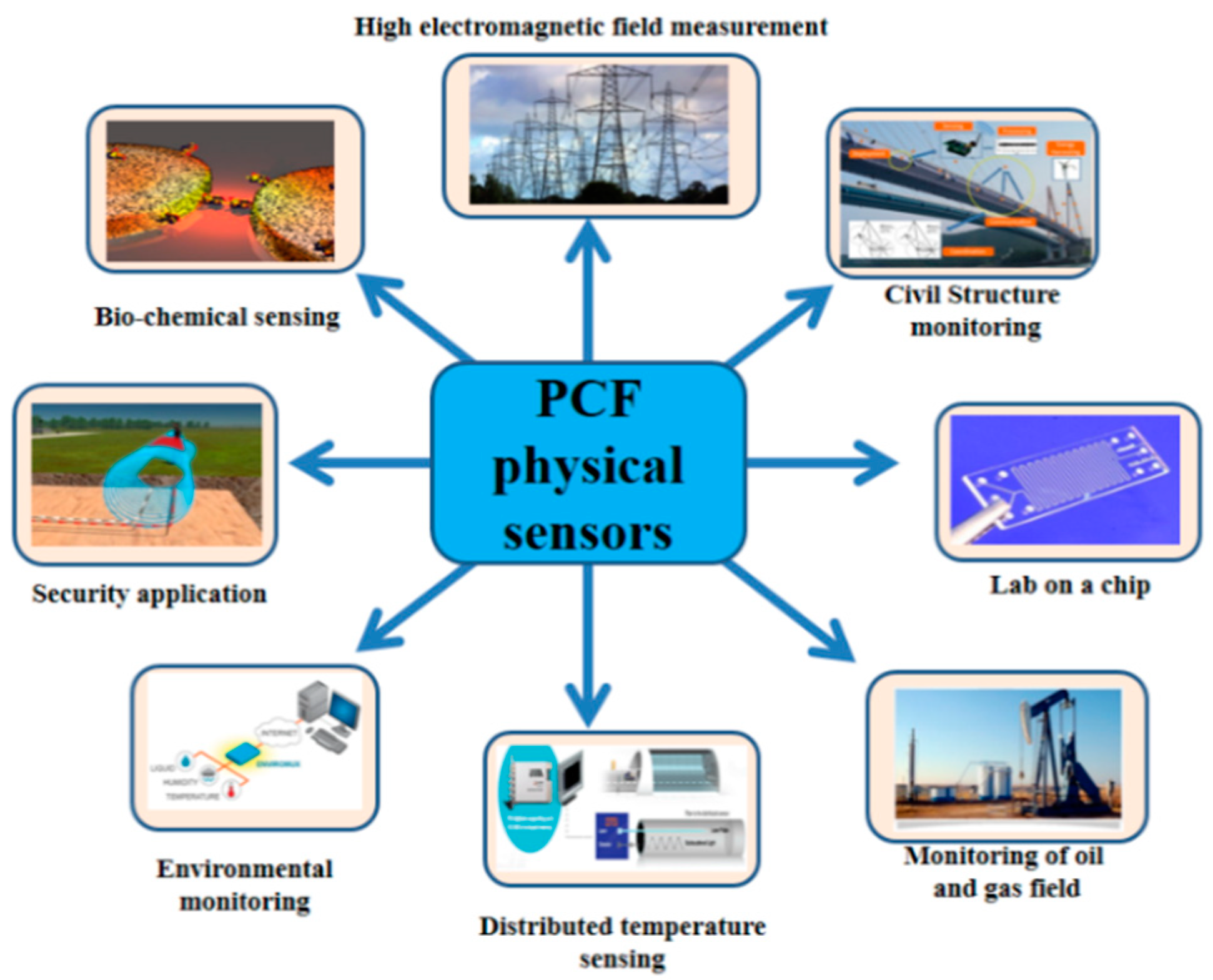
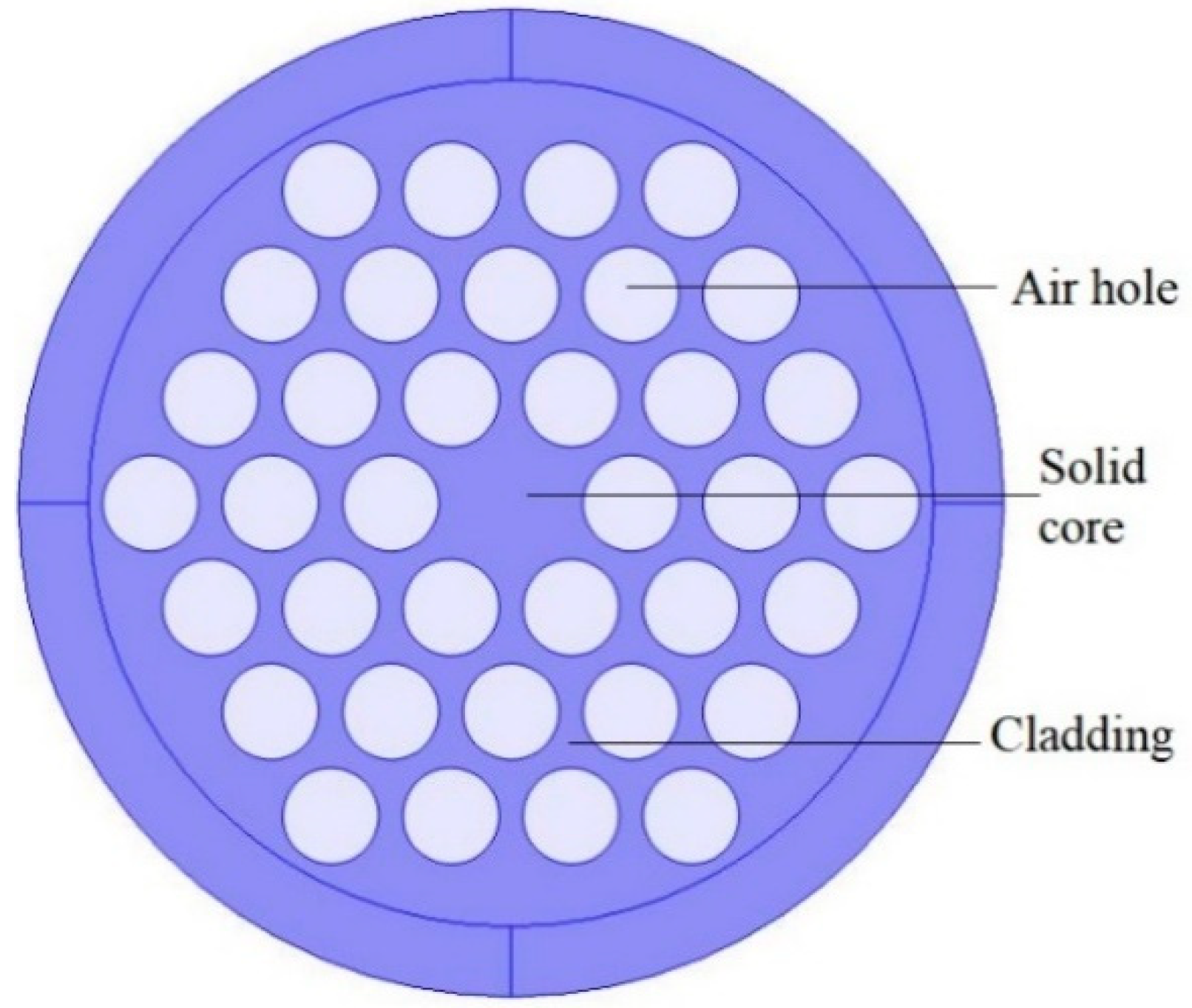
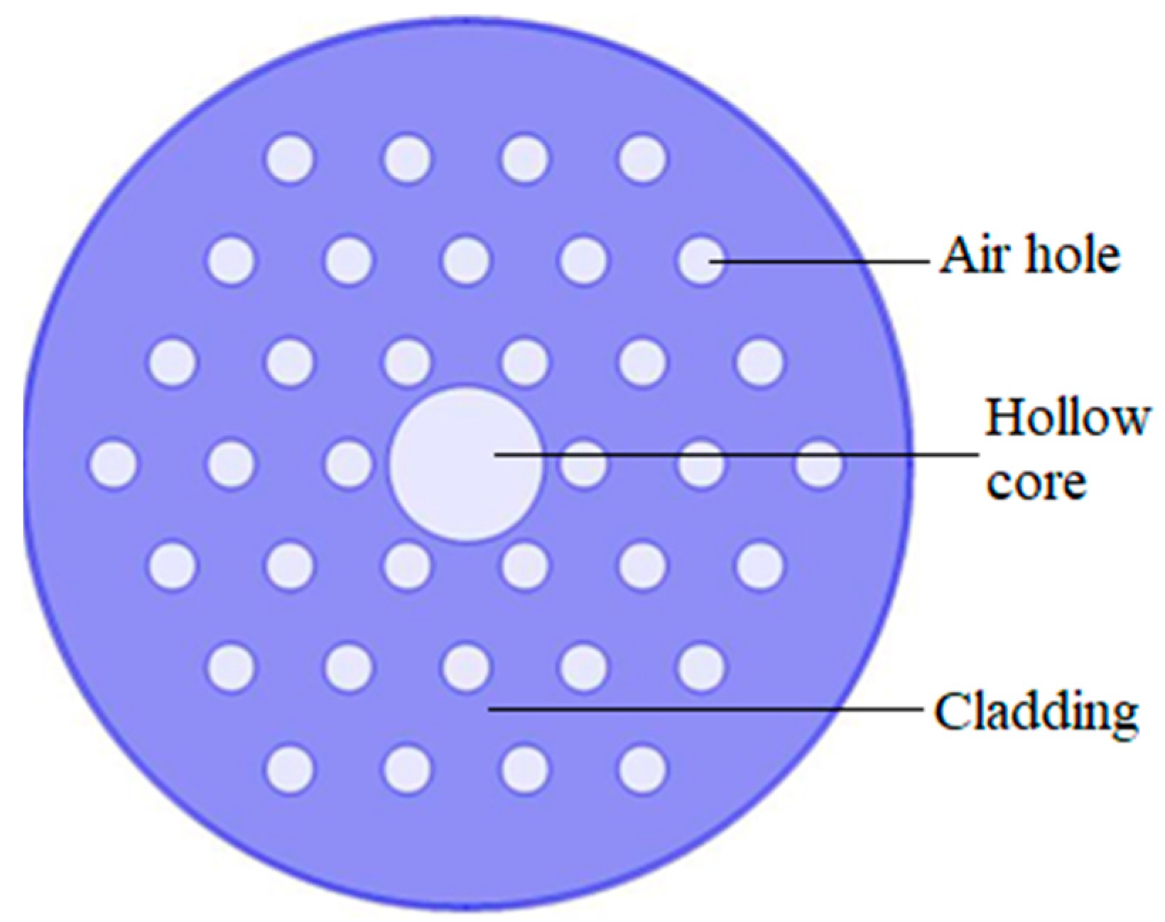
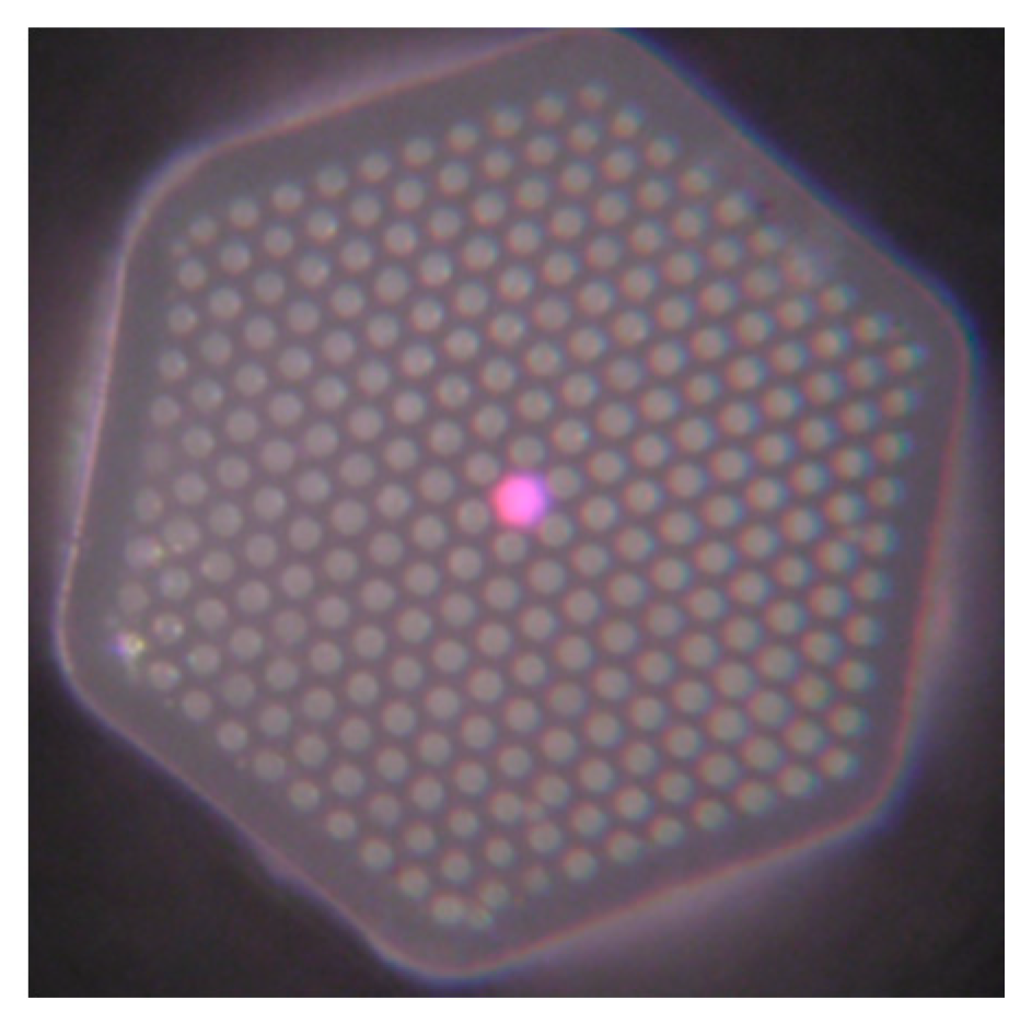
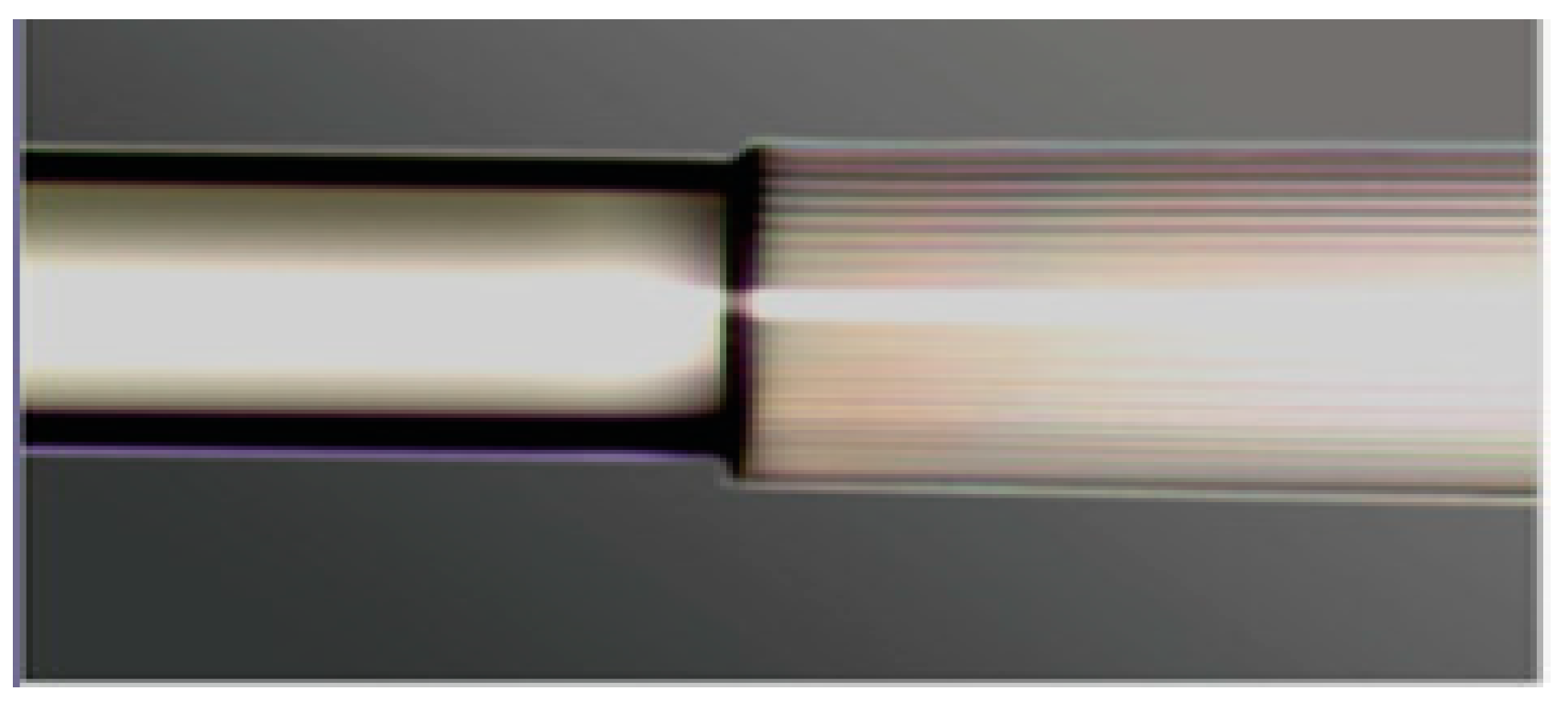
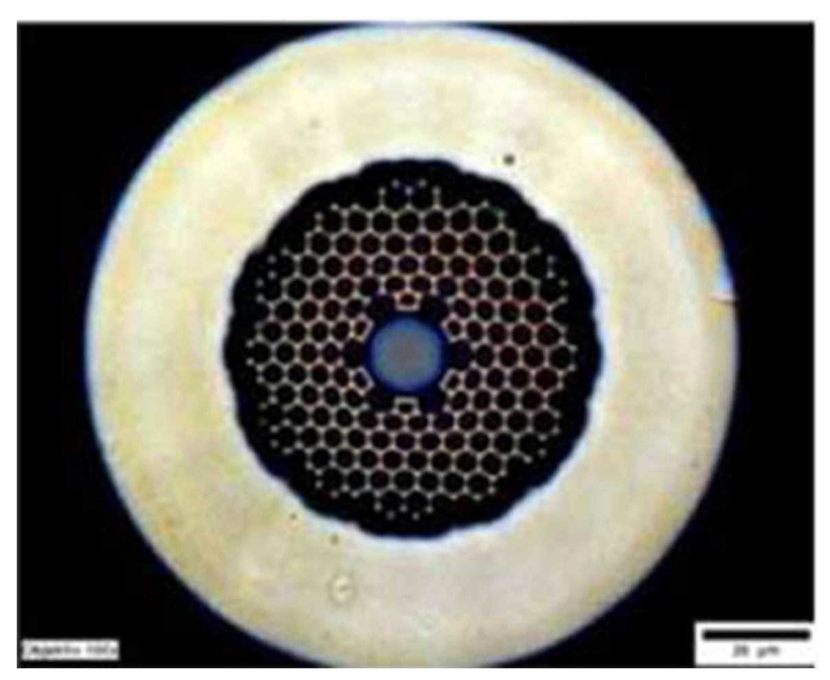
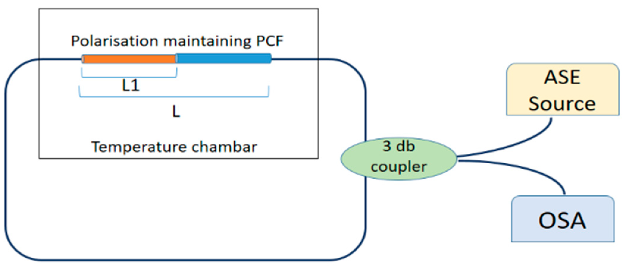
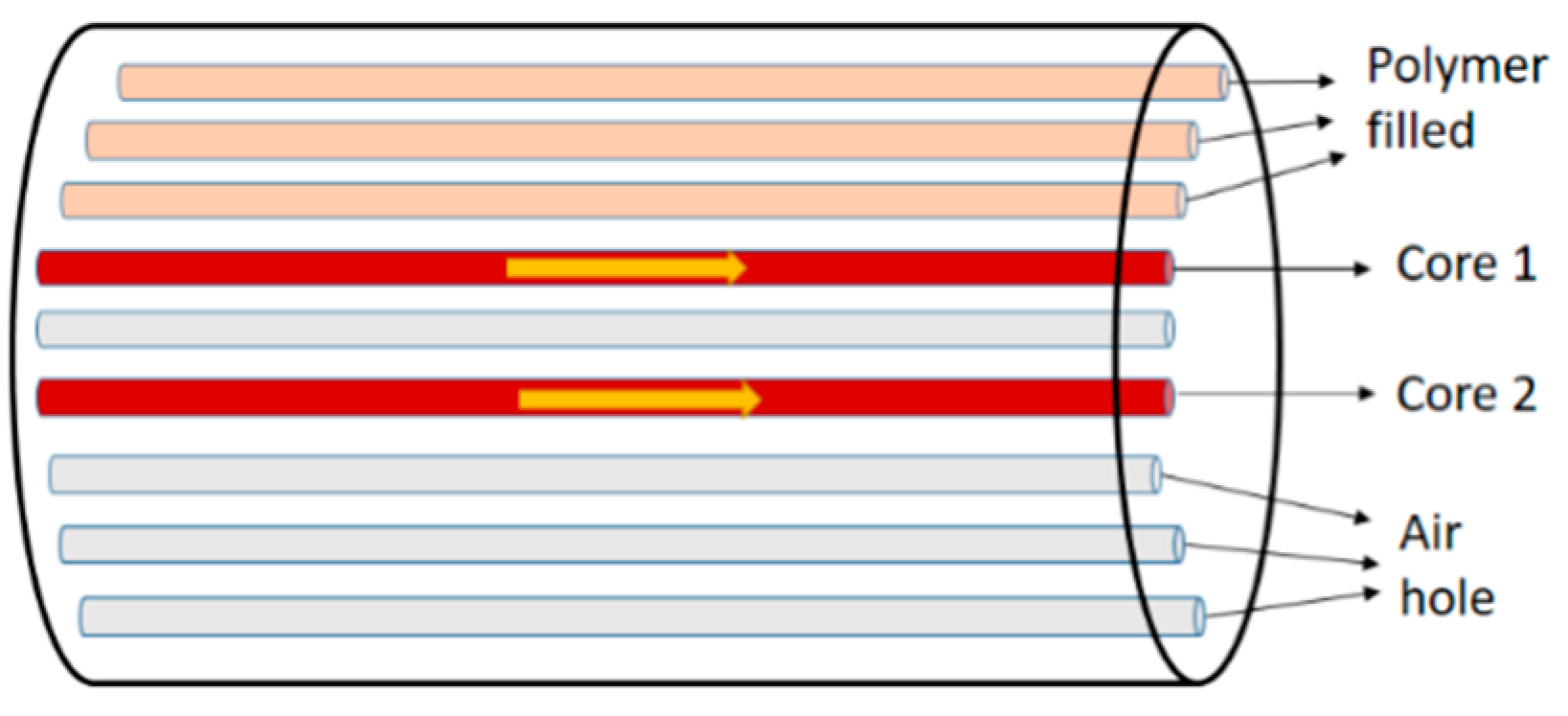
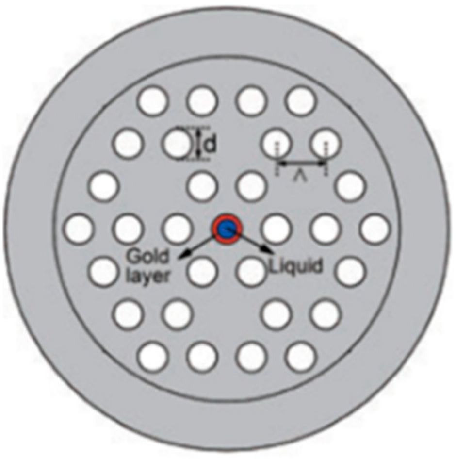
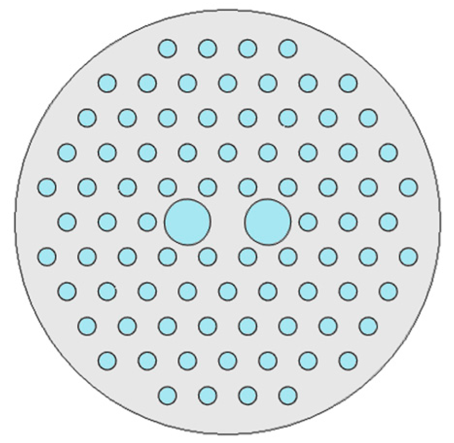
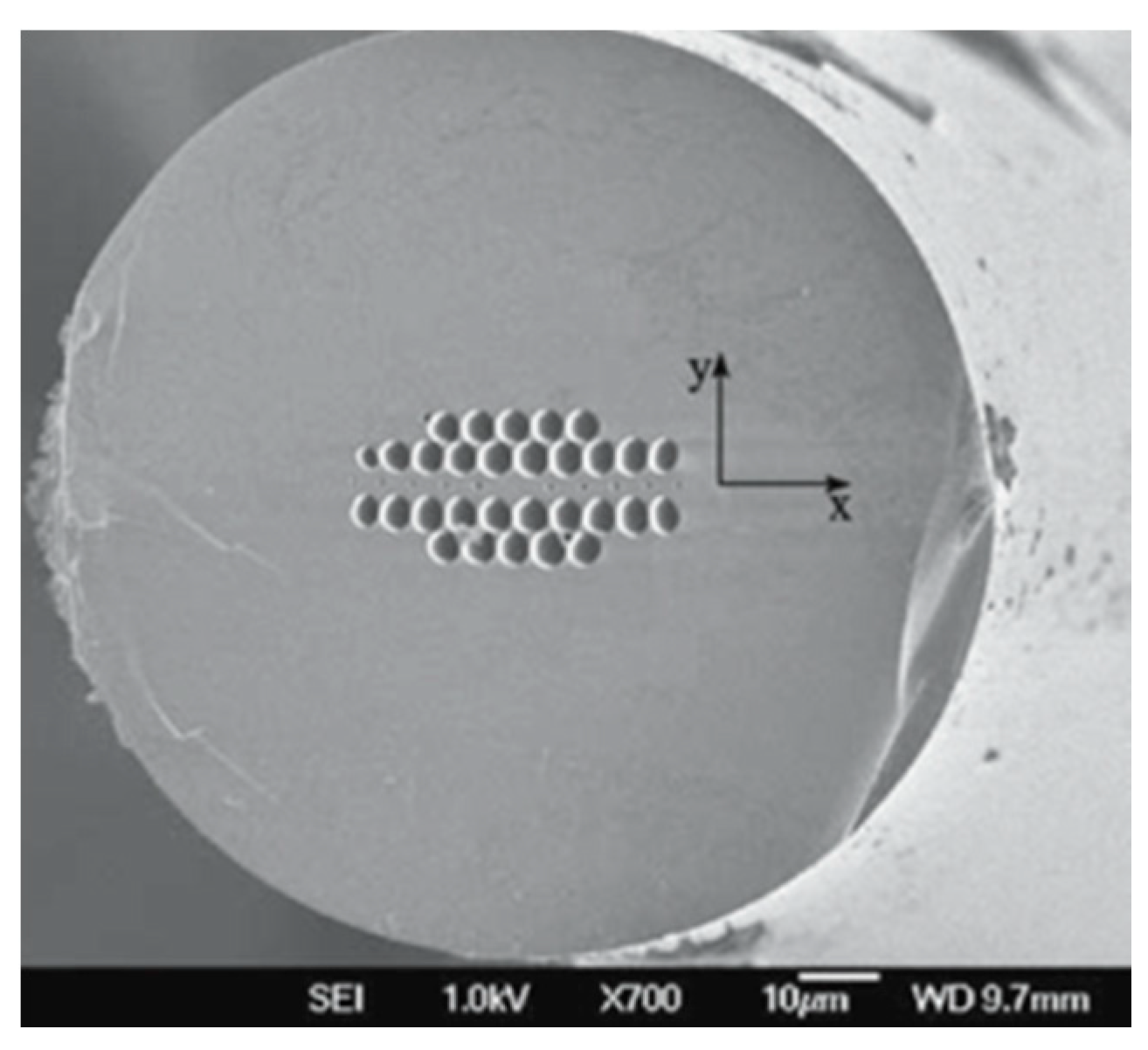
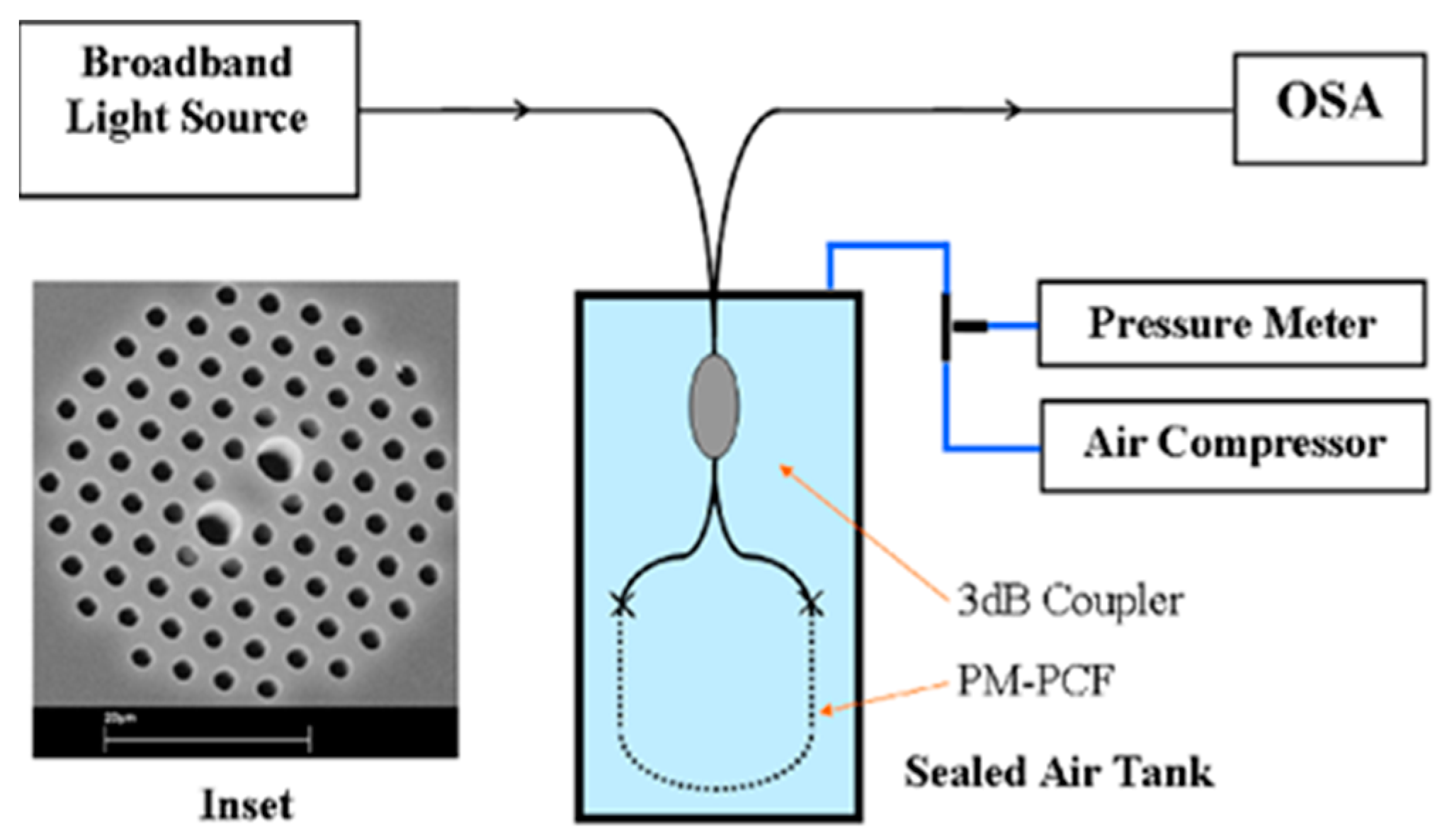
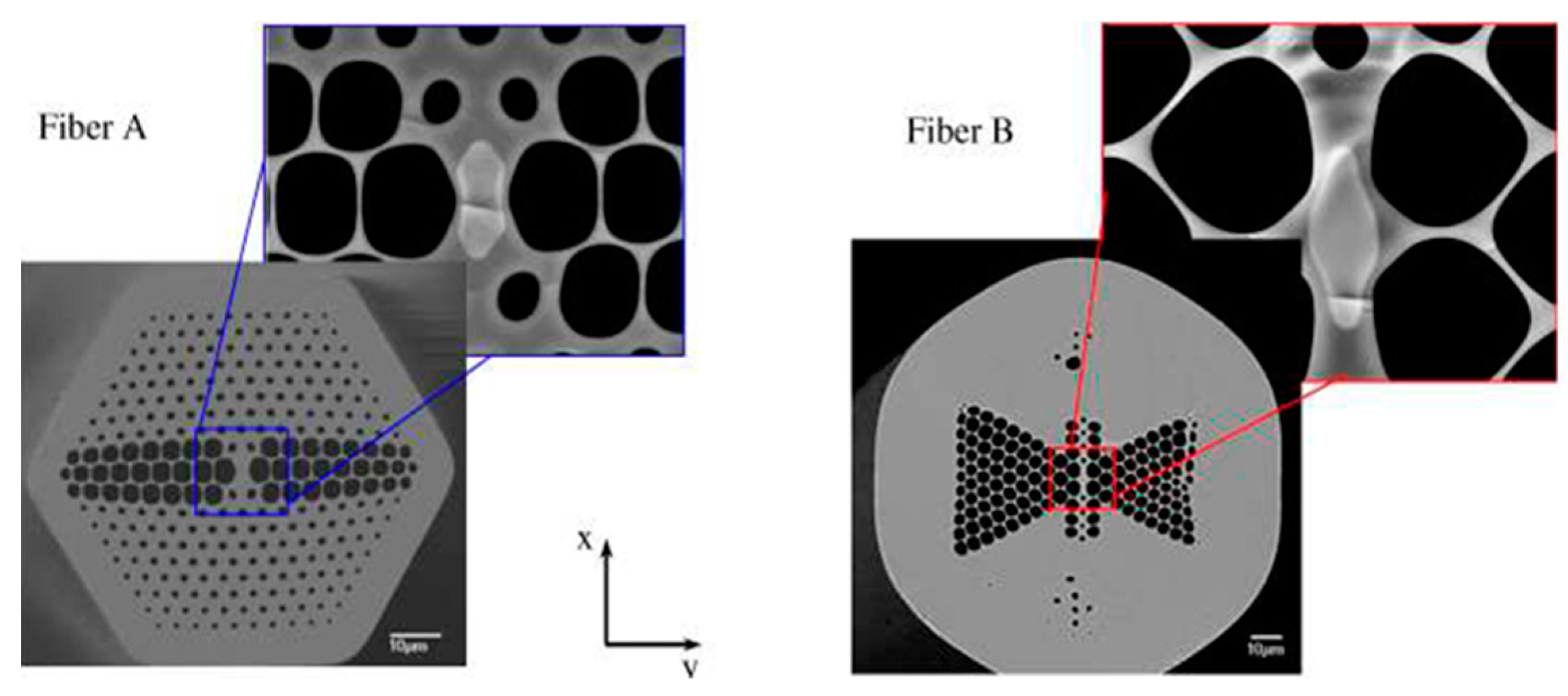
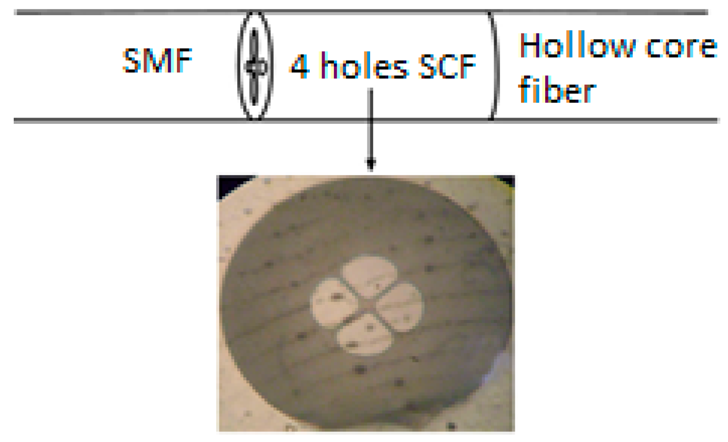
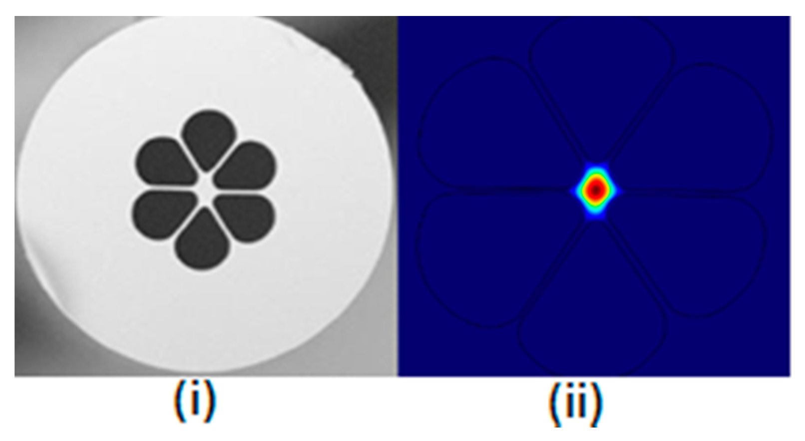
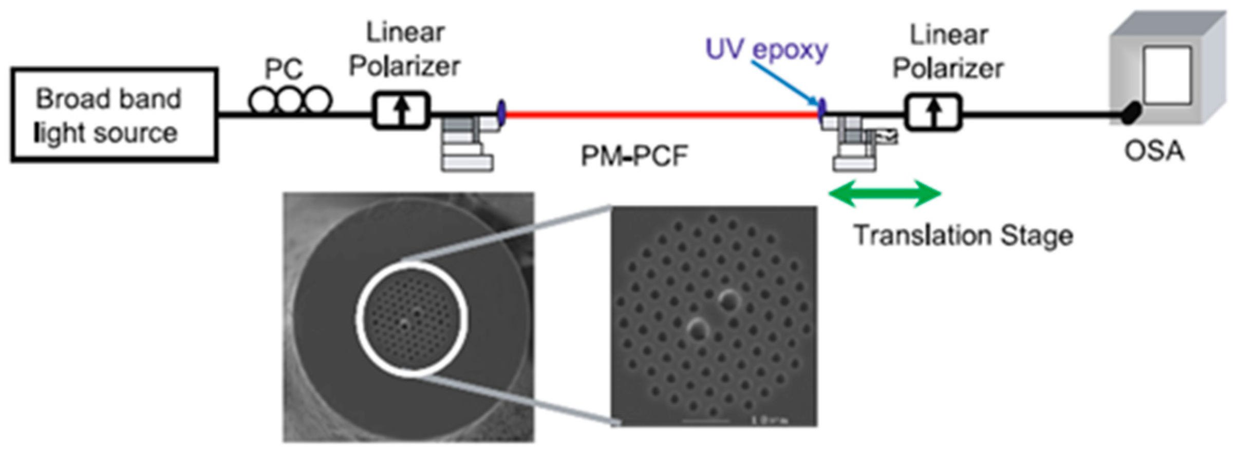
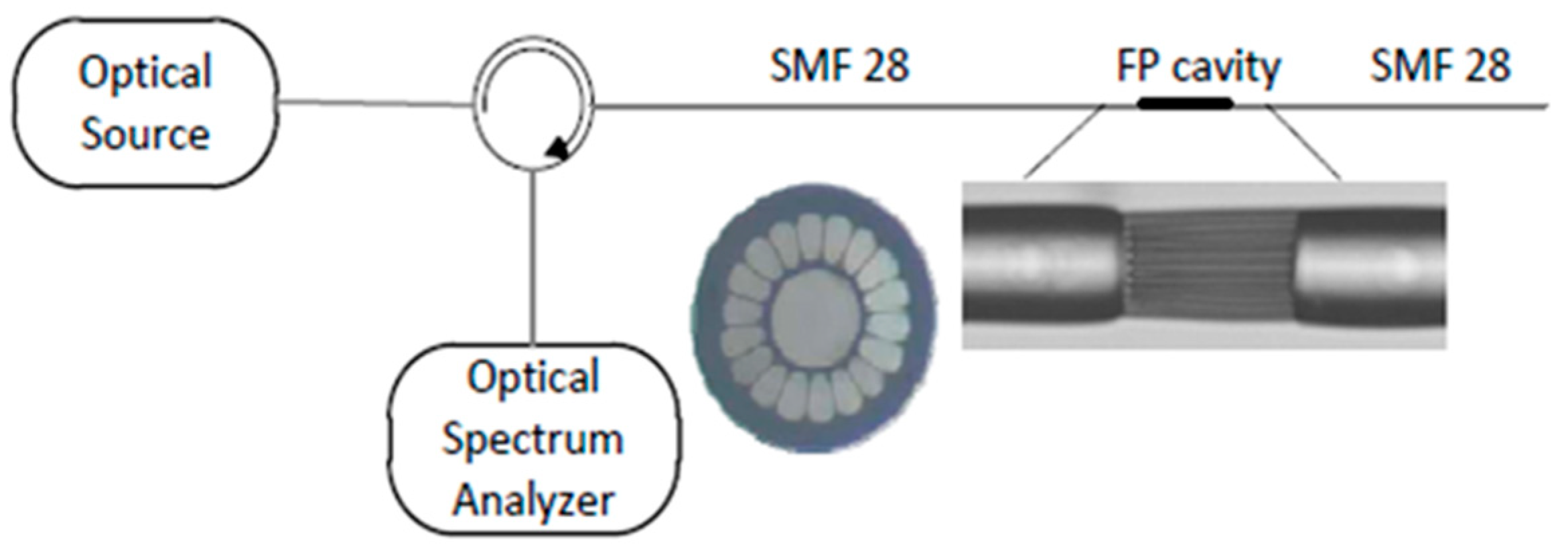
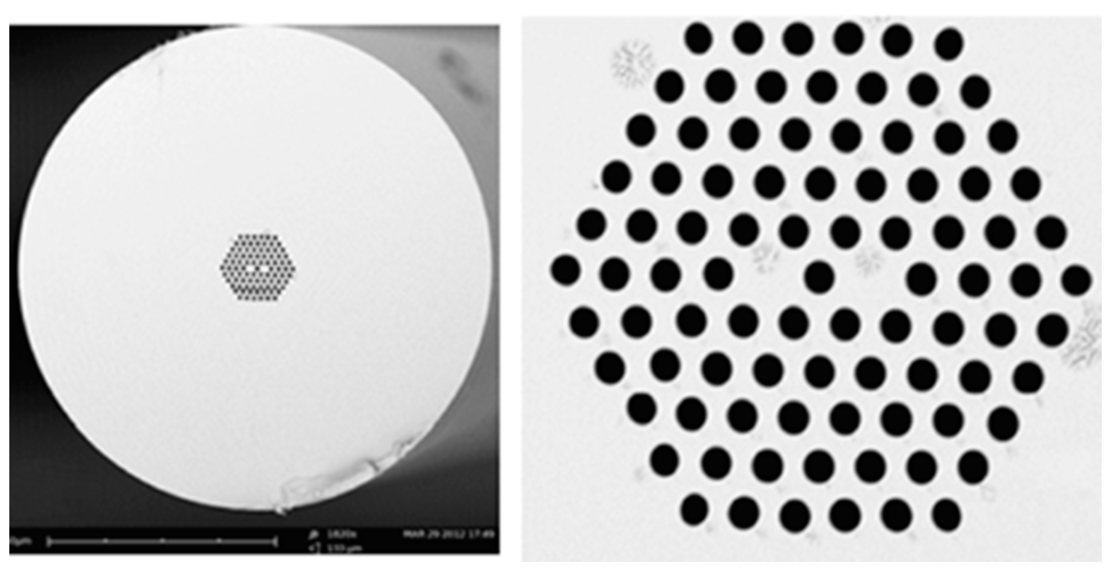
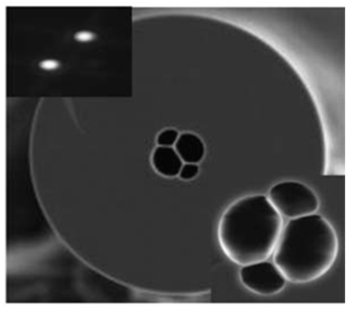
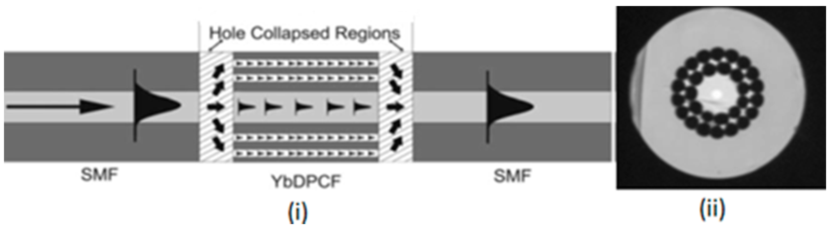
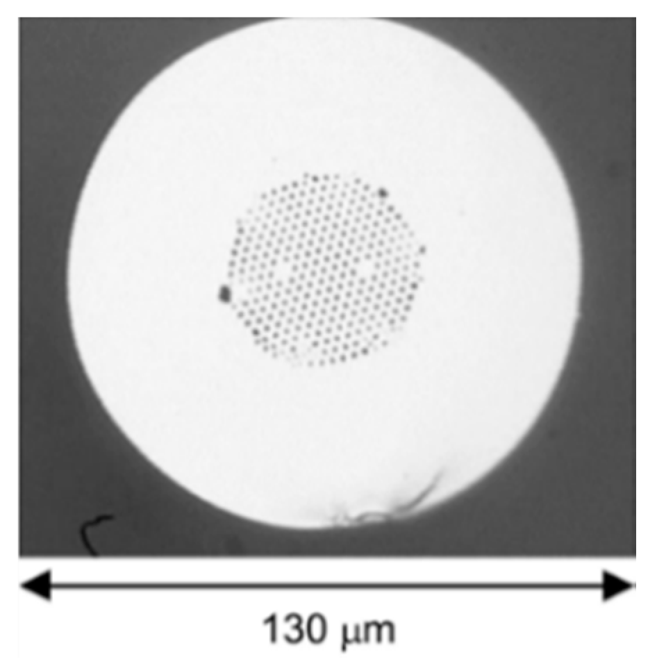
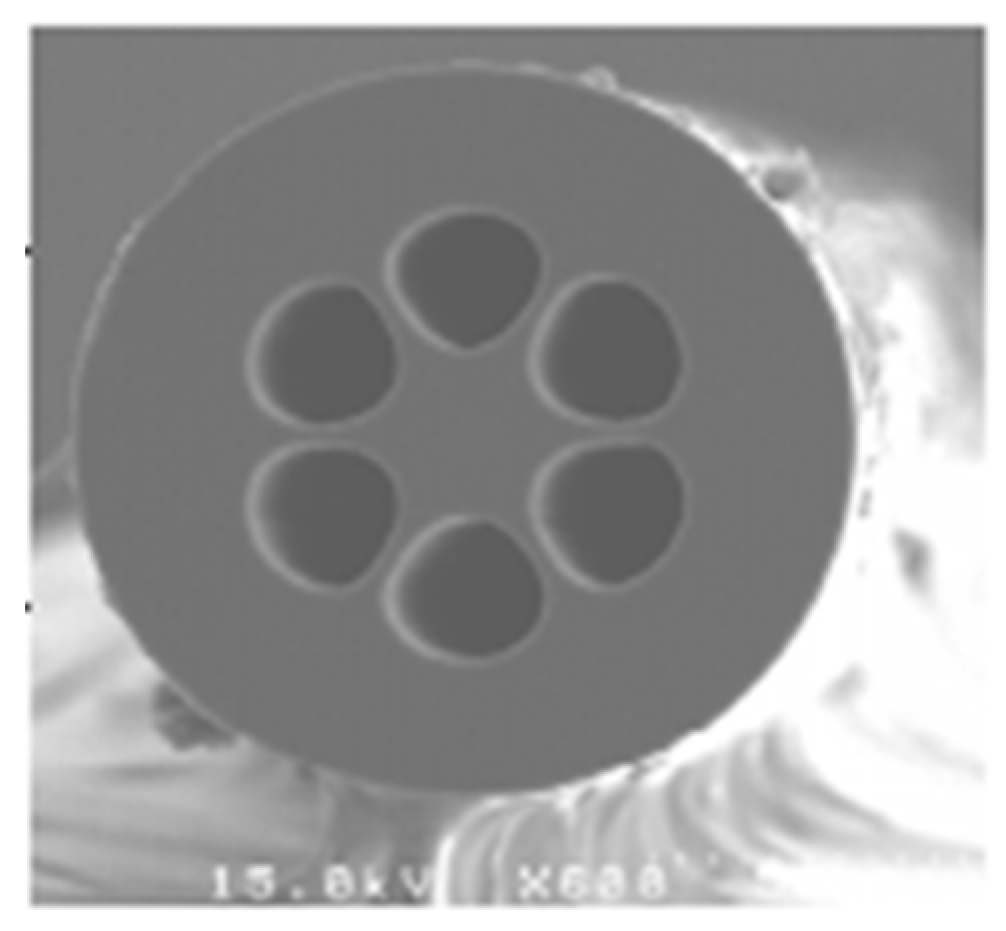
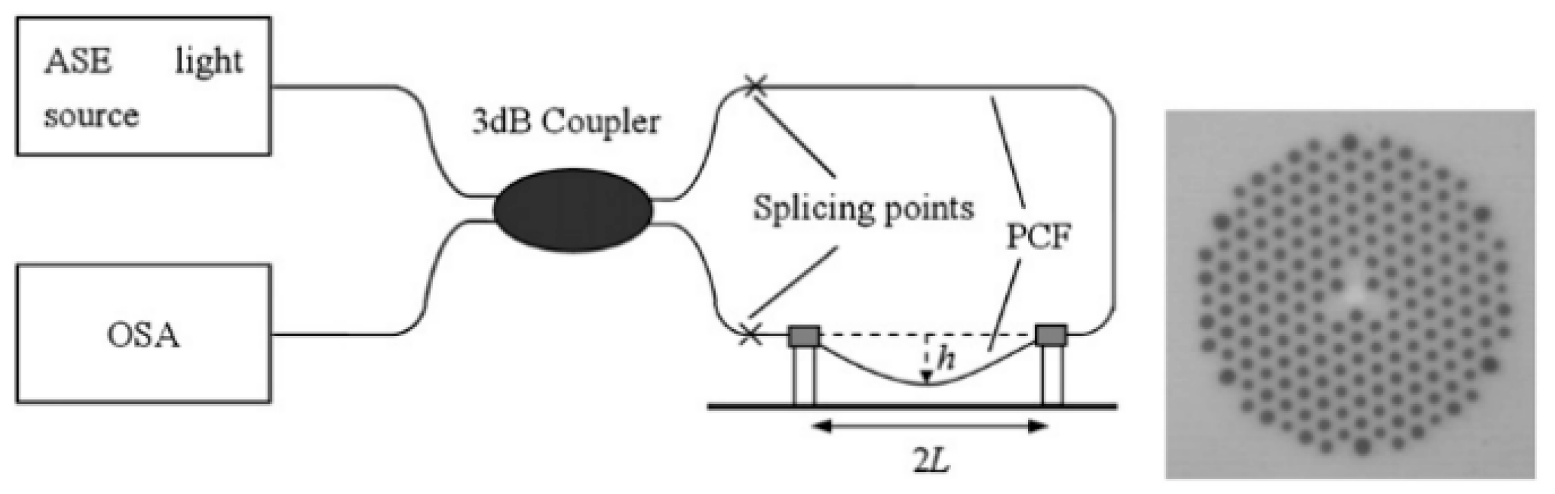
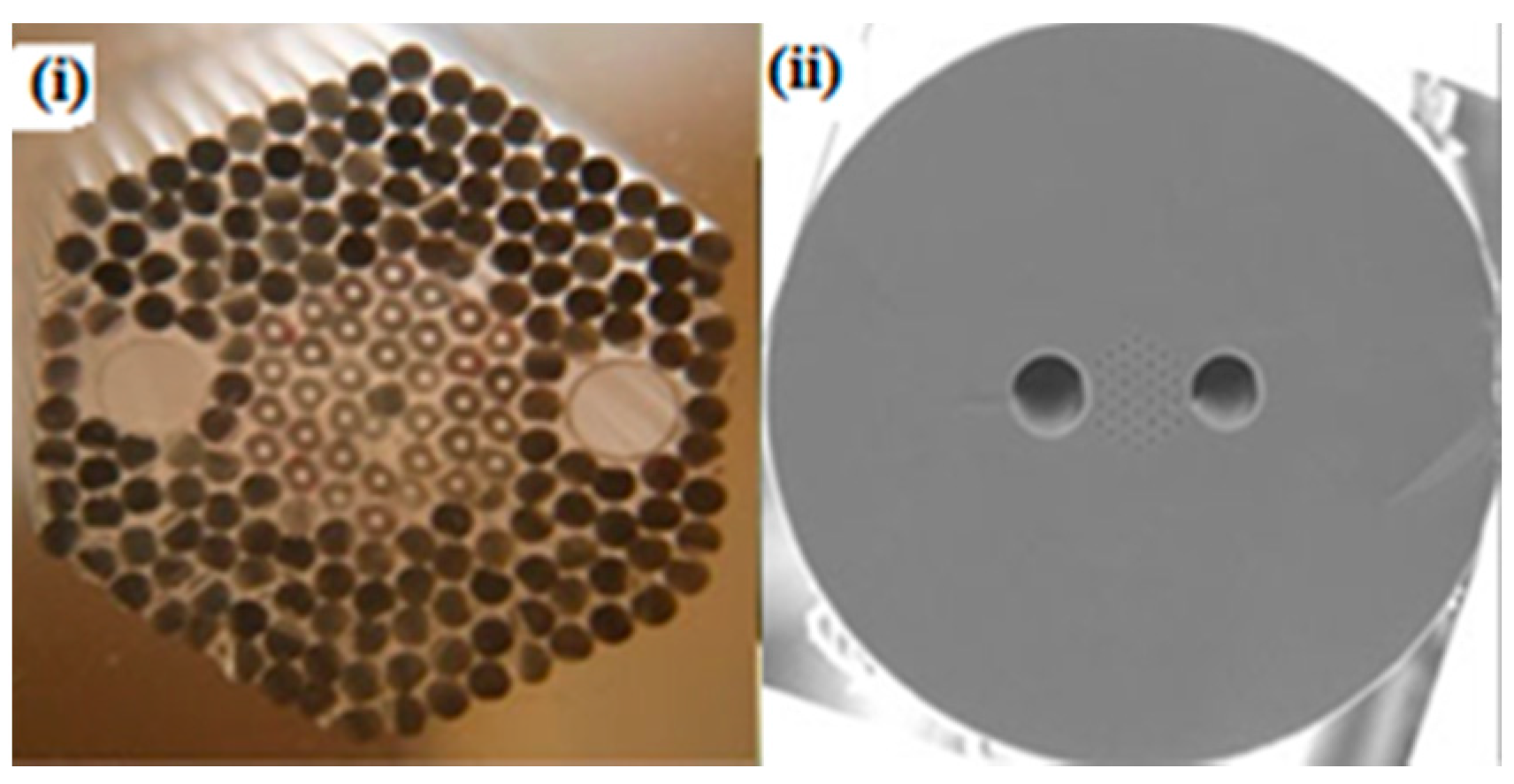
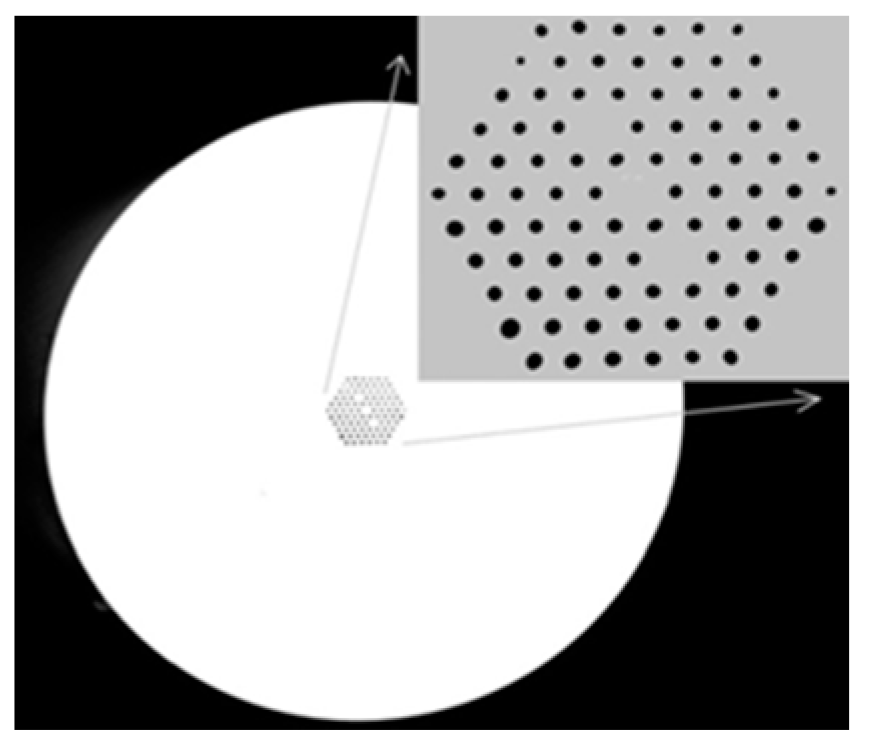
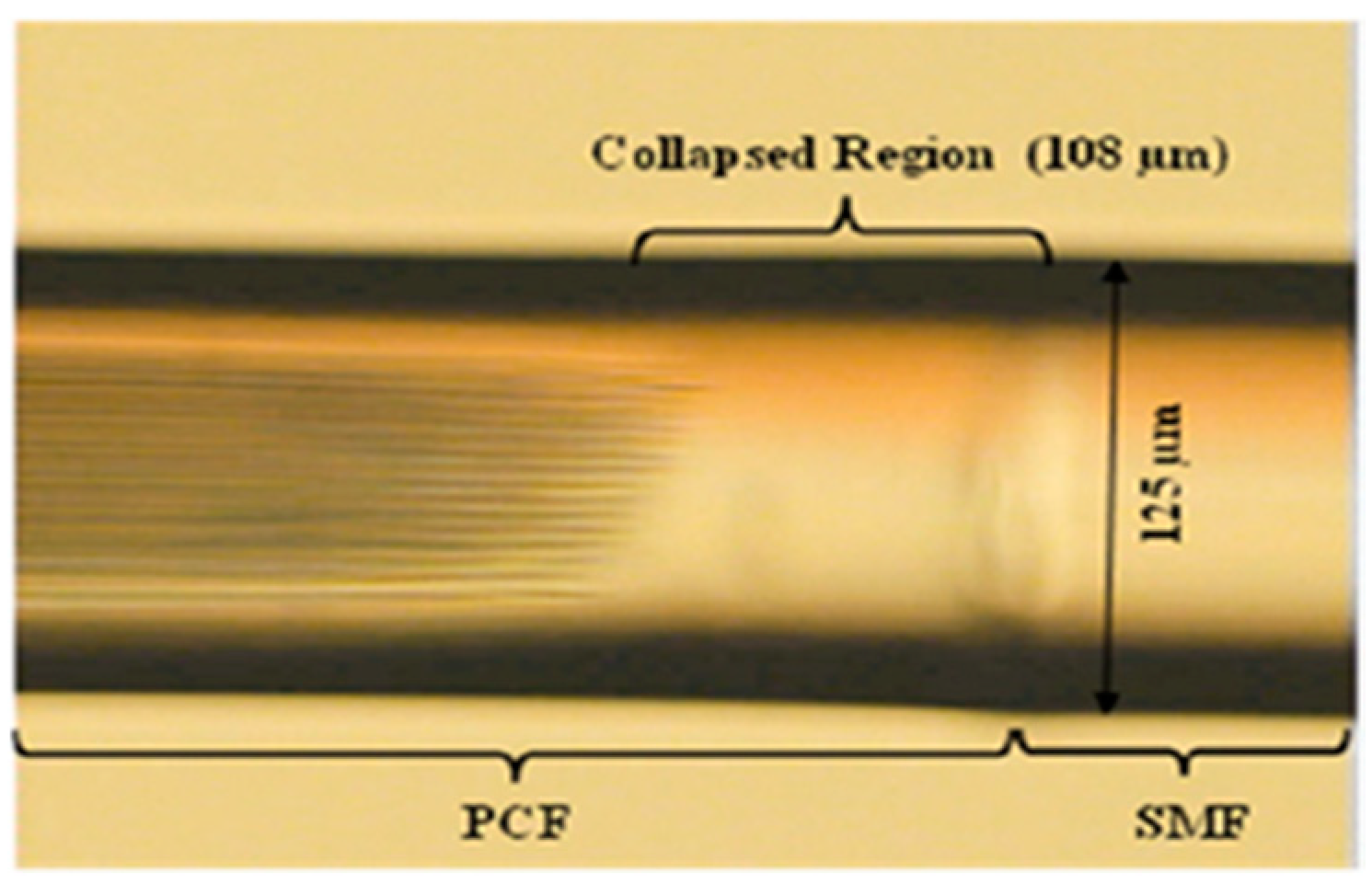
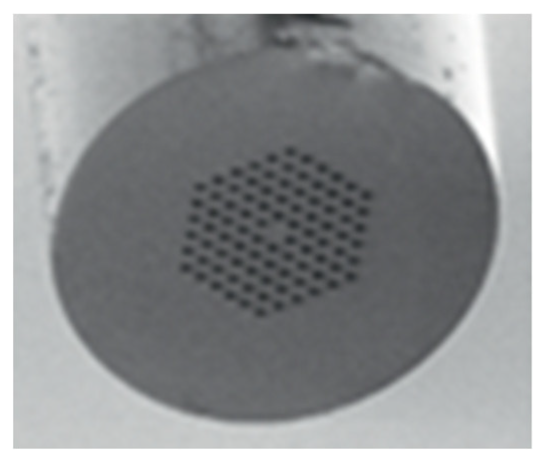
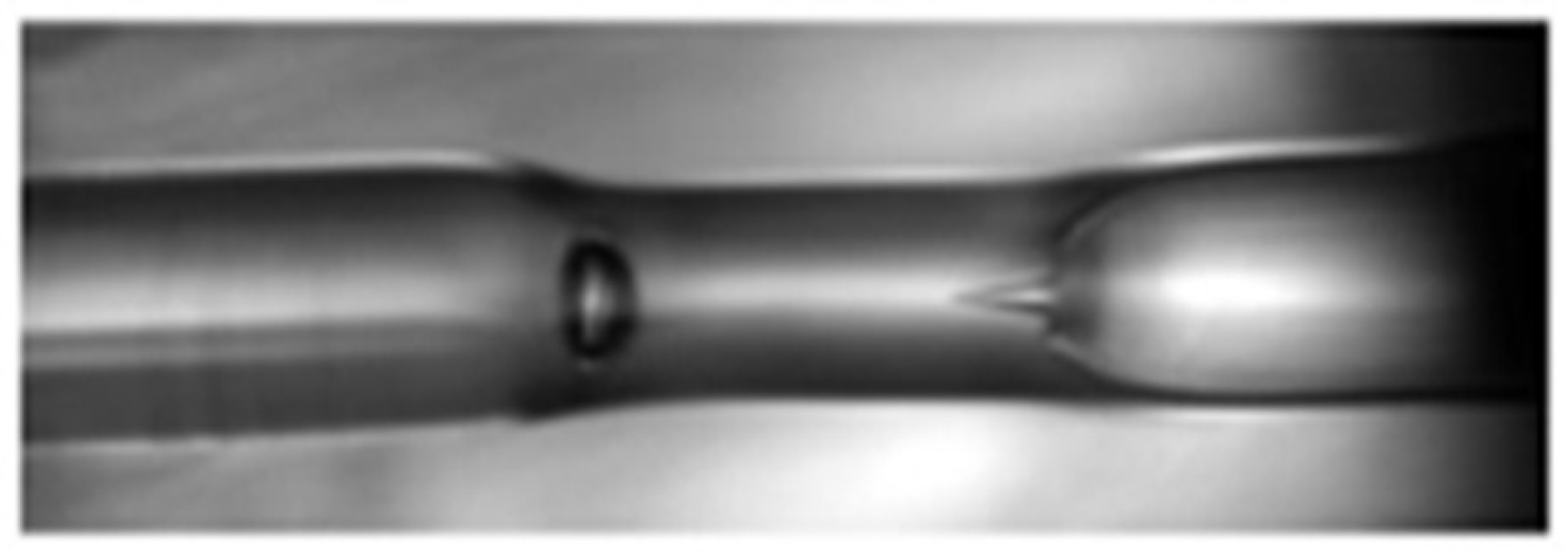
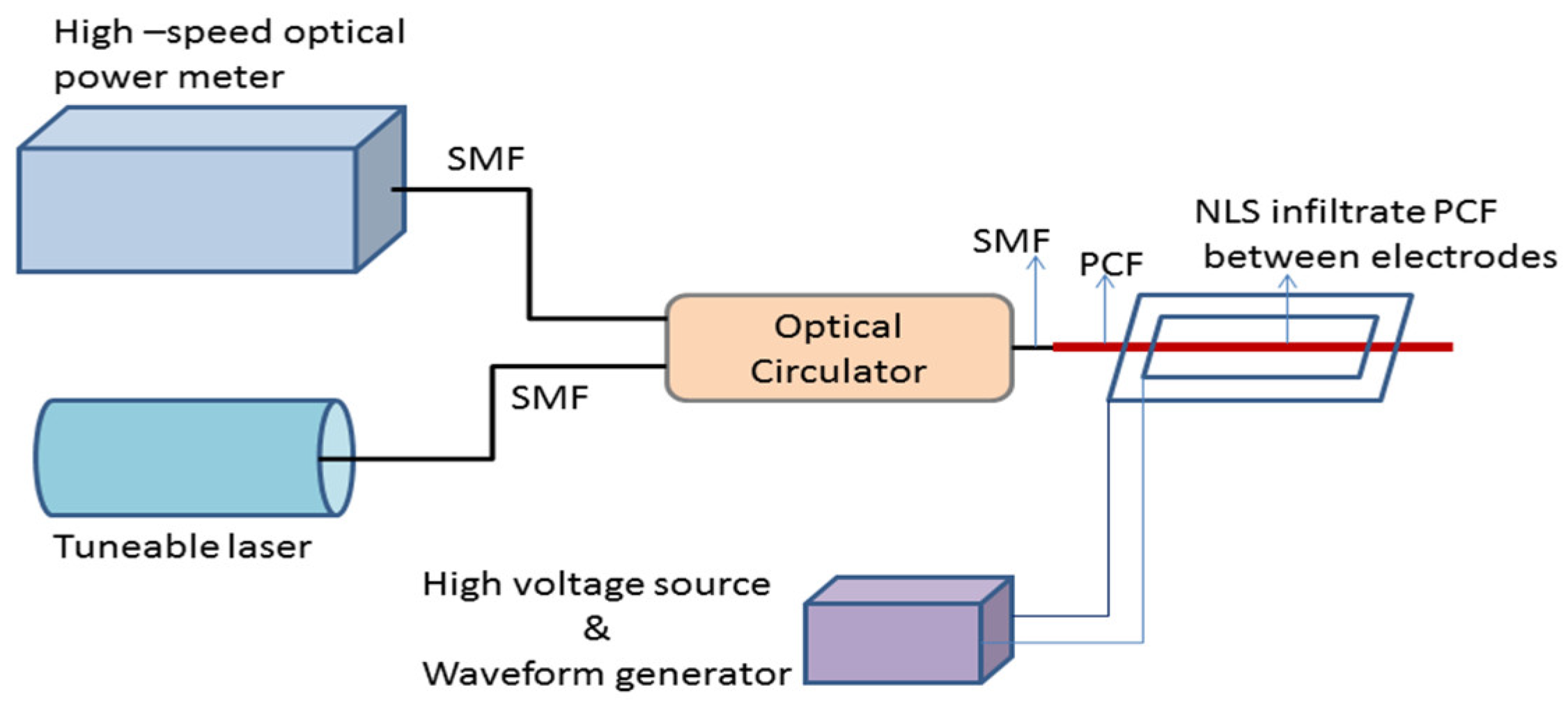
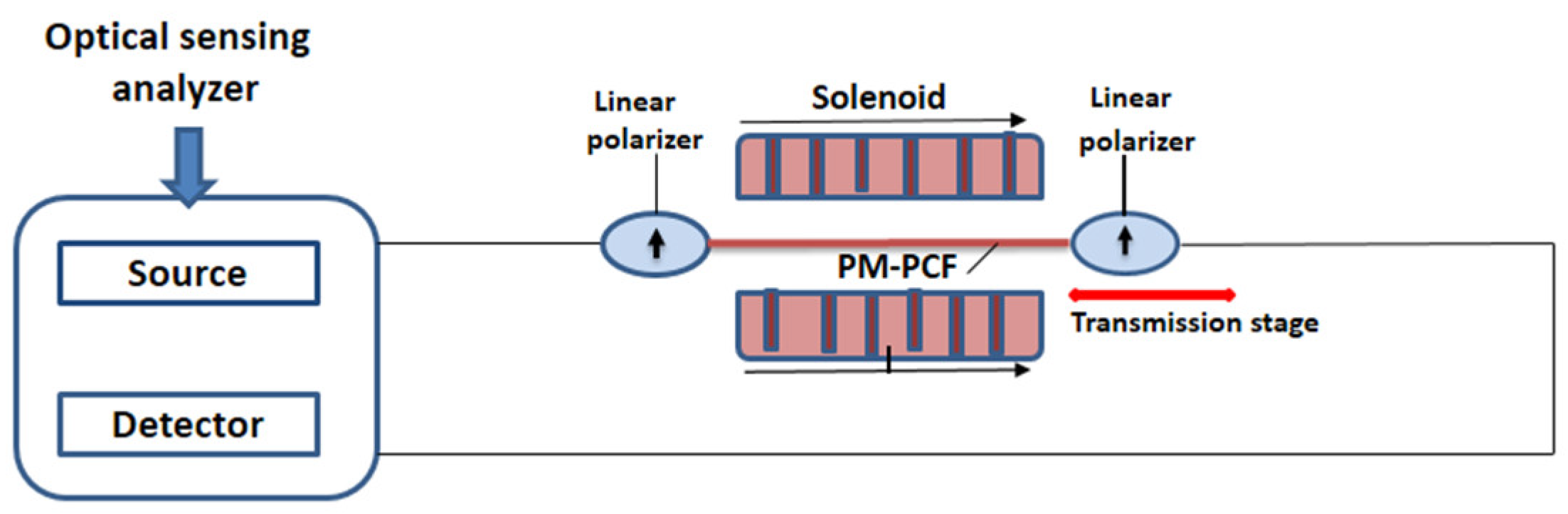
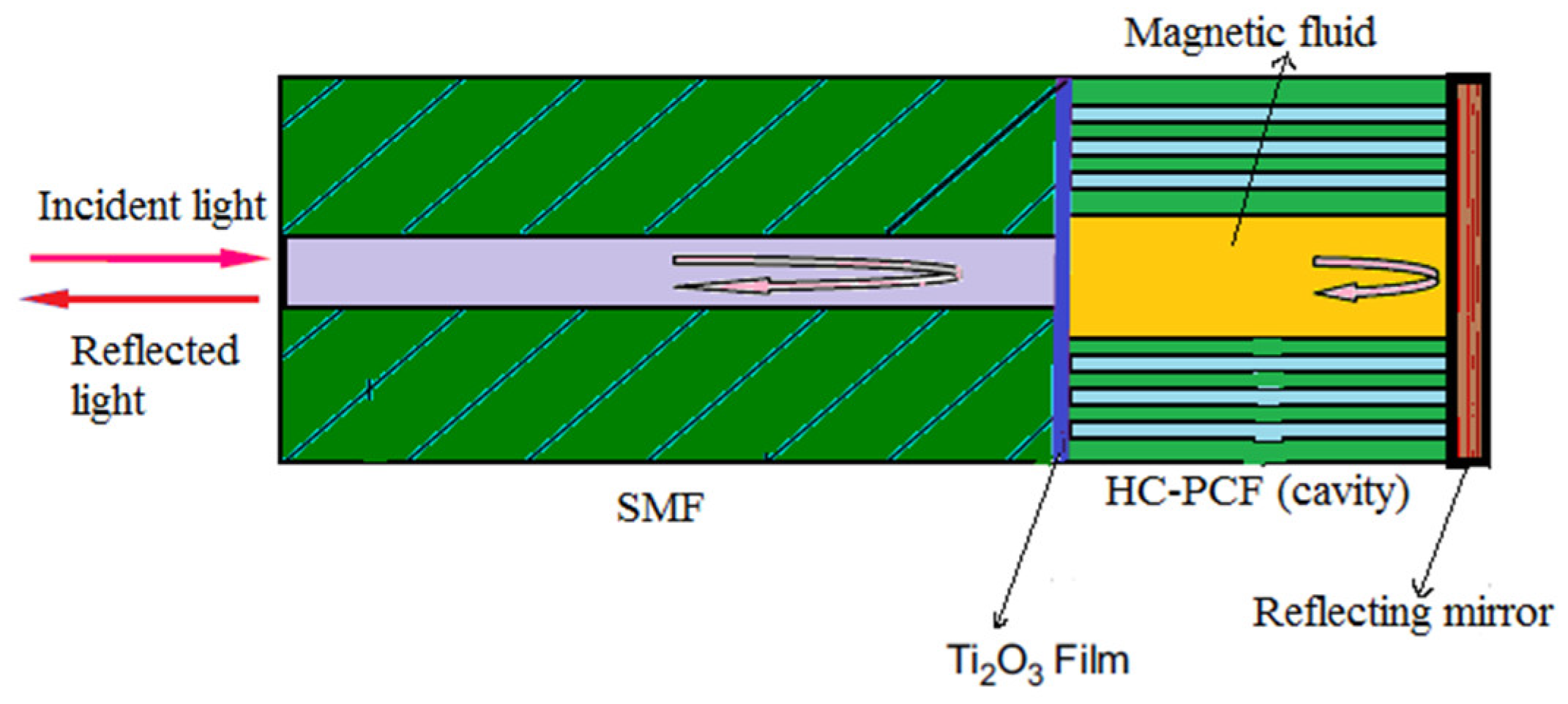
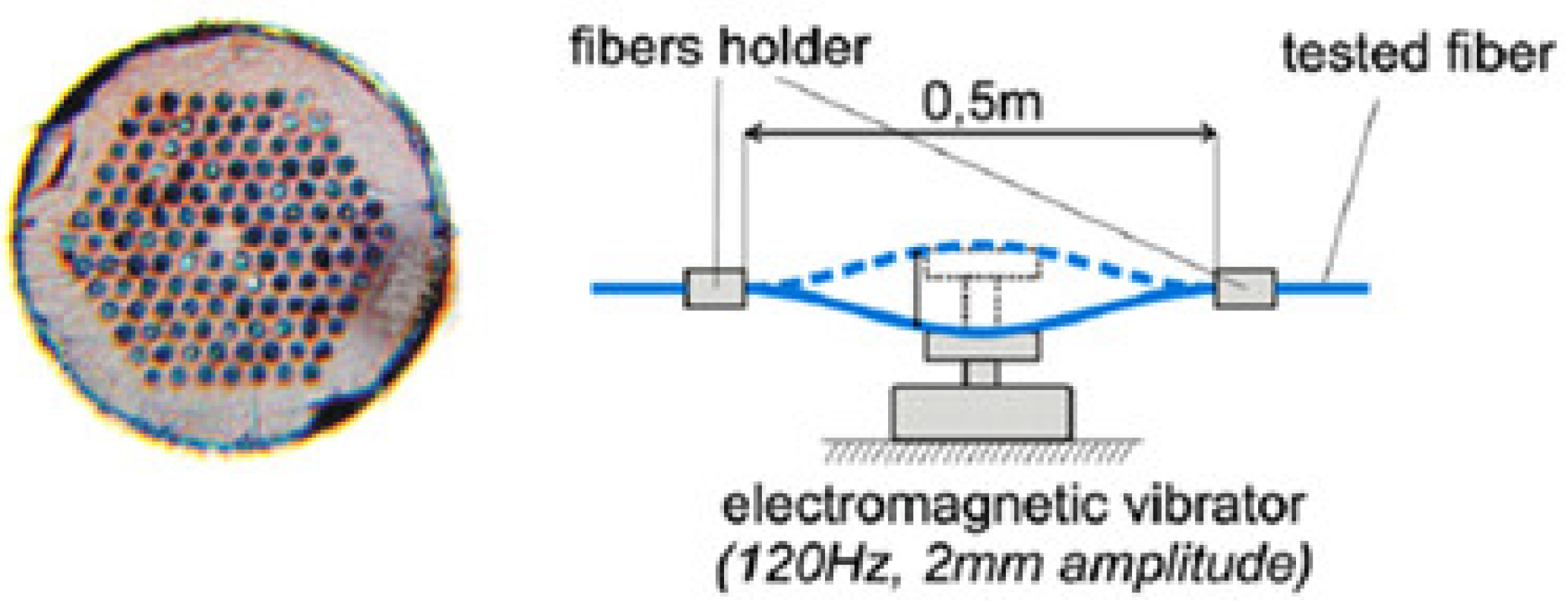
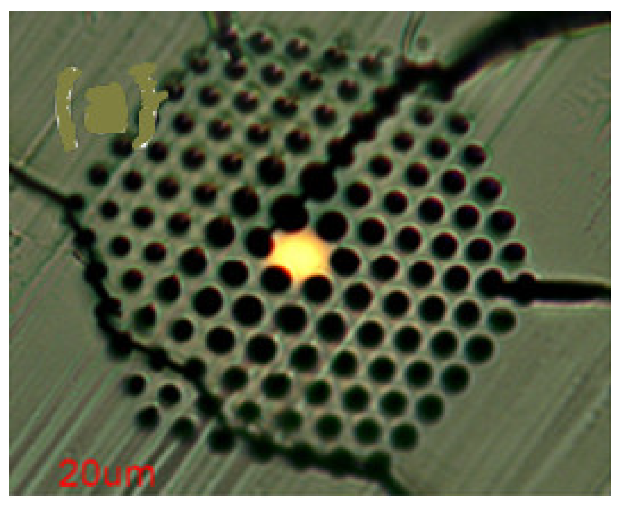
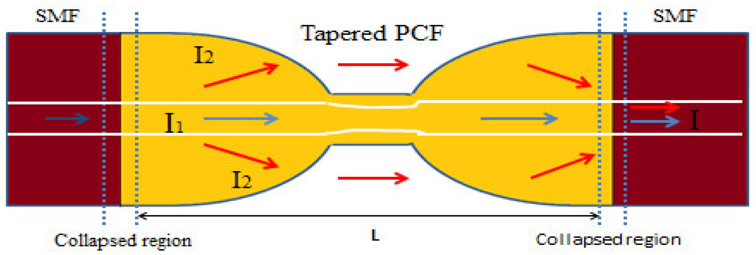
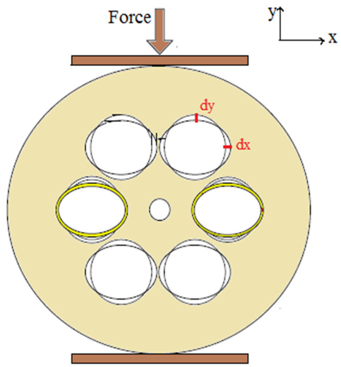
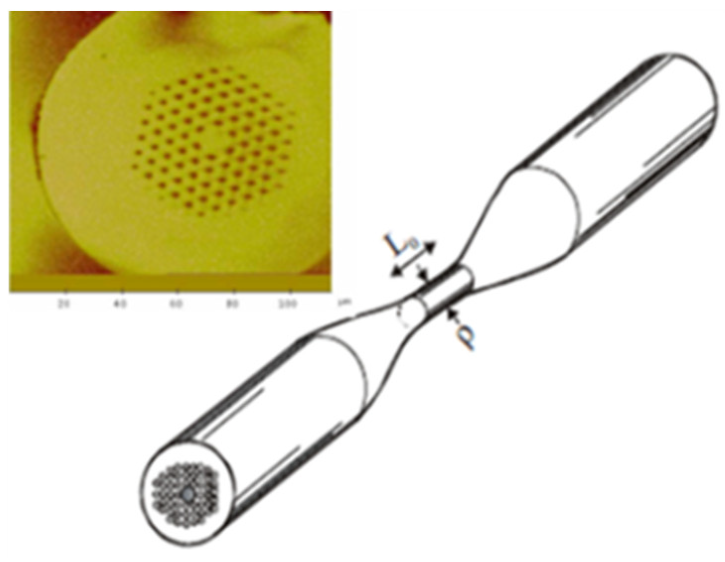
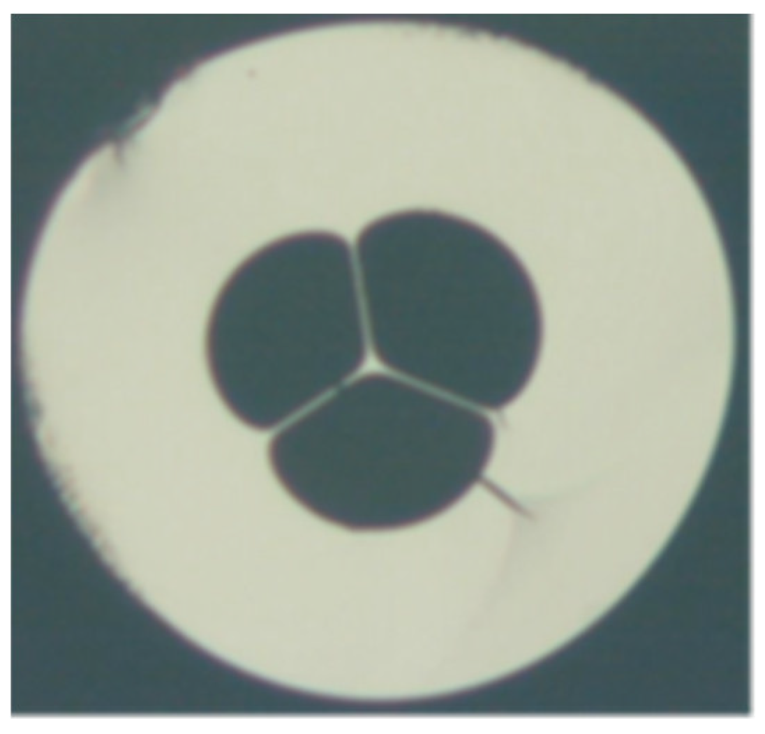
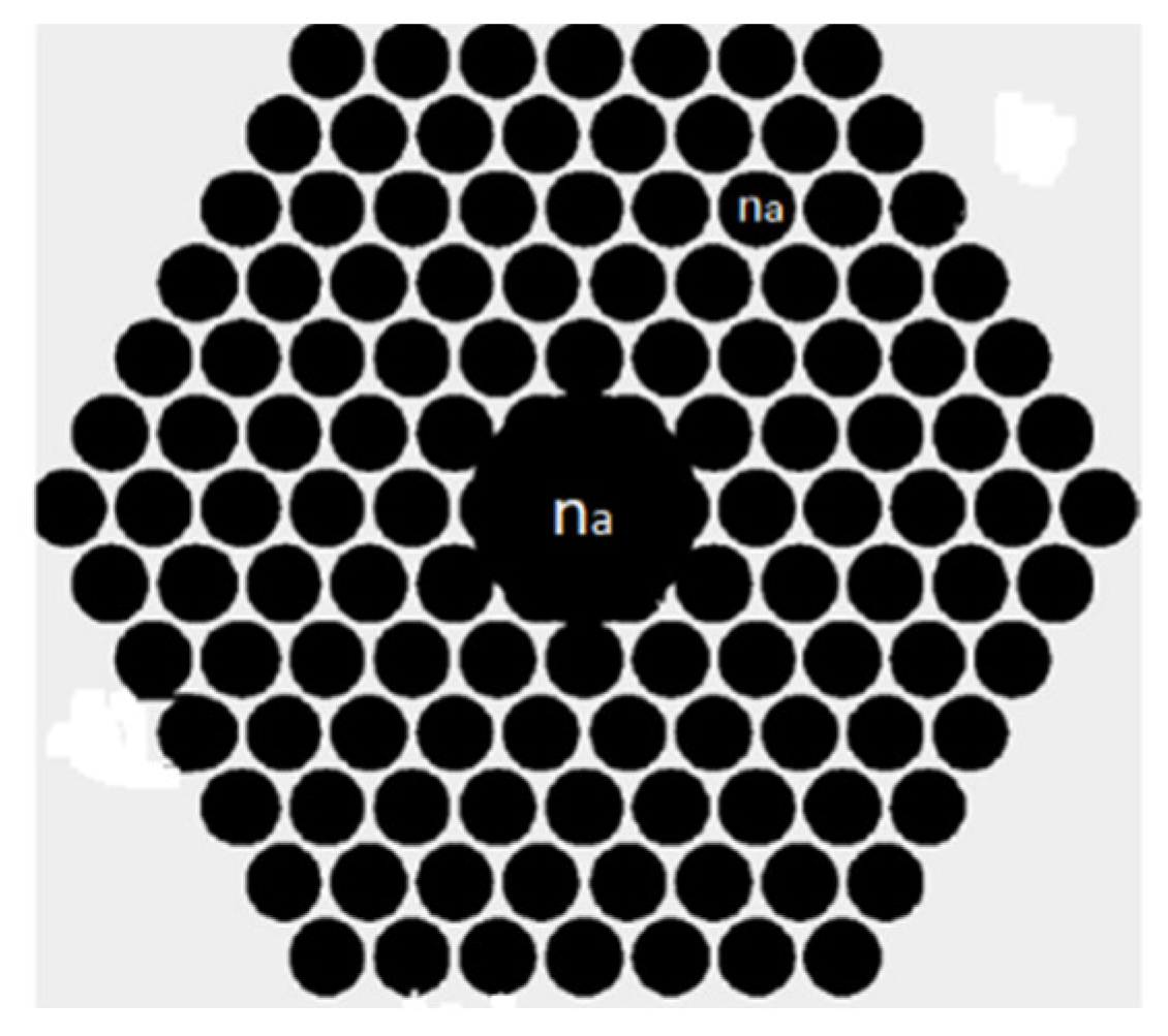
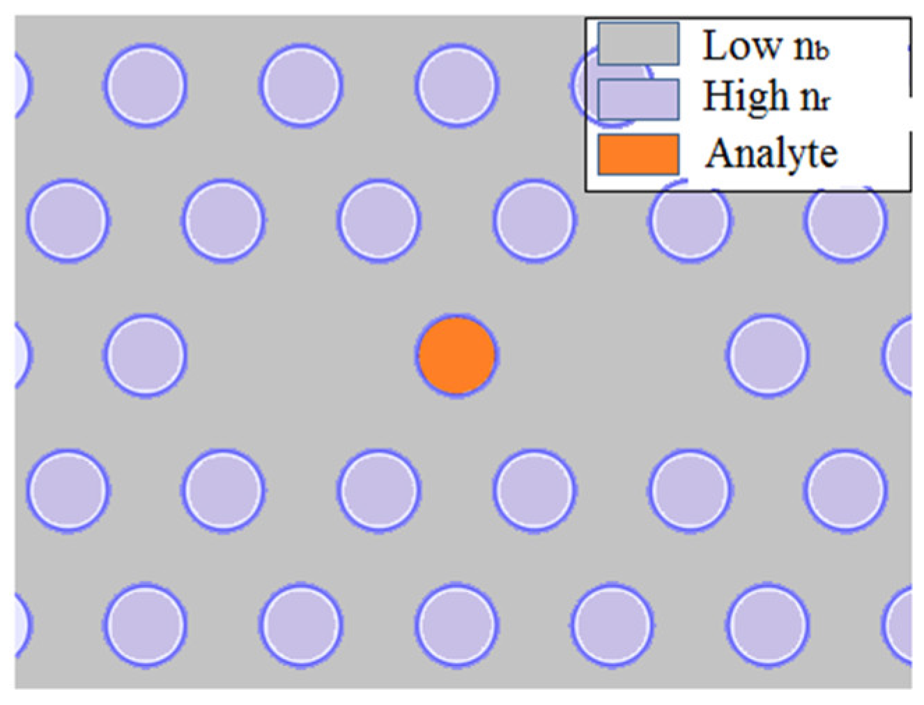
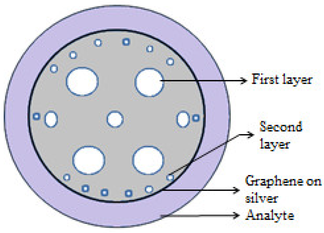
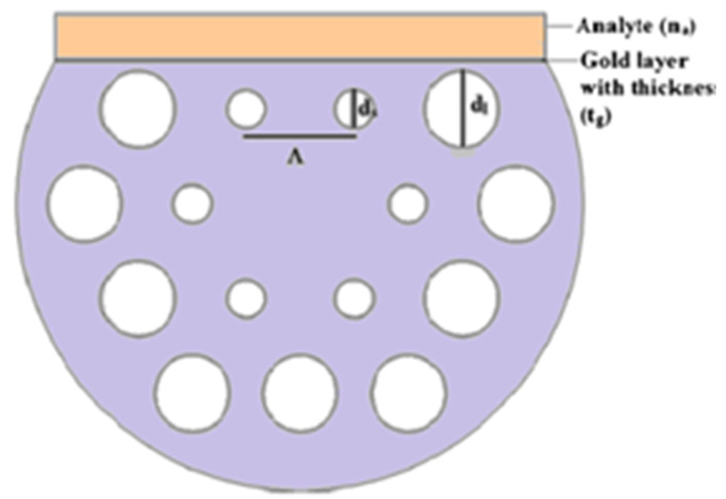
Table 1.
Comparative representation of different PCF-based temperature sensor.
| Reported Structure | Sensing Temperature Range (°C) | Observed Quantity | Sensitivity | Ref. |
|---|---|---|---|---|
| TOPAS polymer optical fiber Bragg grating | 21–33 | Wavelength | −78 pm/°C | [46] |
| Tip interferometer using PCF spliced with SMF | 20–100 | Wavelength | 10 pm/°C | [47] |
| Mach–Zehnder interference technique combined with PCF spliced with MMF | 30–120 | Phase shift/length | 0.4272 radian/°C/cm | [48] |
| Fabry–Perot interferometer-based PCF containing inline microcavity and spliced with SMF | 26–103 | Wavelength | 12 pm/°C | [49] |
| Plasmon resonance-based liquid crystal PCF containing gold nanowire | 30–50 | Wavelength | 10 nm/°C | [50] |
| Microcavity incorporated solid core PCF concatenated with tapered SMF | 40–80 | Power | 0.21 dBm/°C | [51] |
| Compact and liquid infiltrated asymmetric dual elliptical core PCF | 30–34 | Wavelength | 42.99 nm/°C | [52] |
| Multibeam Mach–Zehnder interferometer using a PCF with two asymmetric cores | 25–500 | wavelength | 1.24 pm/°C | [53] |
| Isopropanol-filled PCF long period grating | 20–50 | Wavelength | 1.356 nm/°C | [54] |
| Selectively filled solid core PCF consisting a central air bore | −80 to 90 | Wavelength | −6.02 nm/°C | [55] |
Table 2.
Comparative representation of different PCF-based pressure sensors.
| Reported Structure | More about These Sensors | Sensitivity | Ref. |
|---|---|---|---|
| Periodically tapered long-period gratings combined with PCF | Can measure pressure up to 180 bar | 11.2 pm/bar | [61] |
| Modal interferometer based high birefringence PCF | - | 3.36 nm/MPa | [62] |
| Polarization-maintaining PCF-based Sagnac interferometer for downhole application | Measured at 1320 nm | 4.21 nm/MPa | [63] |
| Side-hole polarization-maintaining PCF | - | −2.30 × 10⁻⁵/MPa | [64] |
| Bragg grating based highly birefringent microstructured optical fiber | Measured at 1550 nm | 33 pm/MPa | [65] |
Table 3.
Comparative representation of different PCF-based strain sensors.
| Reported Structure | Strain Range (µε) | Sensitivity | Ref. |
|---|---|---|---|
| PCF-based long-period fiber-grating | 0–800 | −7.6 pm/µε | [73] |
| PCF-based Mach–Zehnder type interferometers introducing coupling point | 0–3250 | ~2.2 pm/µε | [74] |
| Fiber Bragg gratings photo-written in PCF having refractive index-neutral germanium/fluorine codoped core | 0–3500 | 1.166 pm/με | [75] |
| In-line fiber Mach–Zehnder interferometer using solid core large mode area PCF | 0–2500 | −3 pm/µε | [76] |
| Modified PCF-based Mach–Zehnder interferometer | 0–1300 | 11.22 dB/mε | [77] |
| Fiber ring cavity laser with a photonic crystal fiber PCF in-line Mach–Zehnder interferometer structure | 0–2100 | 2.1 pm/µε | [78] |
| PCF with two asymmetric cores | 0–4000 | −1.59 pm/µε | [53] |
Table 4.
Collective representation of various PCF-based refractive index sensors.
| Reported Structure | Spectral Range (nm) | RI Range | Observed Quantity | Sensitivity | Resolution (RIU) | Ref. |
|---|---|---|---|---|---|---|
| Stable photonic crystal fiber modal interferometer | 1250–1340 | 1.33–1.45 | Interference pattern shift | - | 7 × 10⁻⁵ | [113] |
| Surface long-period gratings incorporated D-shaped photonic crystal fiber | 1250–1650 | 1.00–1.45 | Wavelength | 585.3 nm/RIU | - | [114] |
| Extrinsic cavity formed by a micromirror and a photonic crystal fiber tip which contains a bifunctional lens with large radius of curvature | 1260–1350 | 1.328–1.357 | Intensity | - | 2.60 × 10⁻⁵ | [115] |
| Directional coupler based on PCF polymer fiber | 400–900 | 1.337–1.344 | Wavelength | 1.66 × 10³ nm/RIU | ~2 × 10⁻⁶ | [116] |
| SPR based multicore flat fiber | 1000–1500 | 1.470–1.475 | Wavelength | 23,000 nm/RIU | 4.35 × 10⁻⁶ | [117] |
| Four channel containing PCF combined with gold wire | 1600–2000 | 1.30–1.79 | Wavelength | 3233 nm/RIU | 3.09 × 10⁻⁵ | [118] |
| D shaped PCF combined with metamaterials | 755–830 | 1.34–1.36 | Wavelength | 3700 nm/RIU | 2.70 × 10⁻⁵ | [119] |
| Gold nanowire consisting solid core PCF | 600–1100 | 1.27–1.36 | Wavelength | 2350 nm/RIU | 2.8 × 10⁻⁵ | [120] |
| SPR based dual polarized spiral PCF | 550–850 | 1.33–1.38 | Wavelength | 4600 nm/RIU | - | [121] |
| Dual core based microstructured optical fiber | 500–900 | 1.35–1.51 | Wavelength | 7000 nm/RIU | 7 × 10⁻⁶ | [122] |
© 2019 by the authors. Licensee MDPI, Basel, Switzerland. This article is an open access article distributed under the terms and conditions of the Creative Commons Attribution (CC BY) license (http://creativecommons.org/licenses/by/4.0/).
Share and Cite
MDPI and ACS Style
De, M.; Gangopadhyay, T.K.; Singh, V.K. Prospects of Photonic Crystal Fiber as Physical Sensor: An Overview. Sensors 2019, 19, 464. https://doi.org/10.3390/s19030464
AMA Style
De M, Gangopadhyay TK, Singh VK. Prospects of Photonic Crystal Fiber as Physical Sensor: An Overview. Sensors. 2019; 19(3):464. https://doi.org/10.3390/s19030464
Chicago/Turabian StyleDe, Moutusi, Tarun Kumar Gangopadhyay, and Vinod Kumar Singh. 2019. "Prospects of Photonic Crystal Fiber as Physical Sensor: An Overview" Sensors 19, no. 3: 464. https://doi.org/10.3390/s19030464
Note that from the first issue of 2016, this journal uses article numbers instead of page numbers. See further details here.