Recent Advances in Fabrication Methods for Flexible Antennas in Wearable Devices: State of the Art

 , , and
Abstract
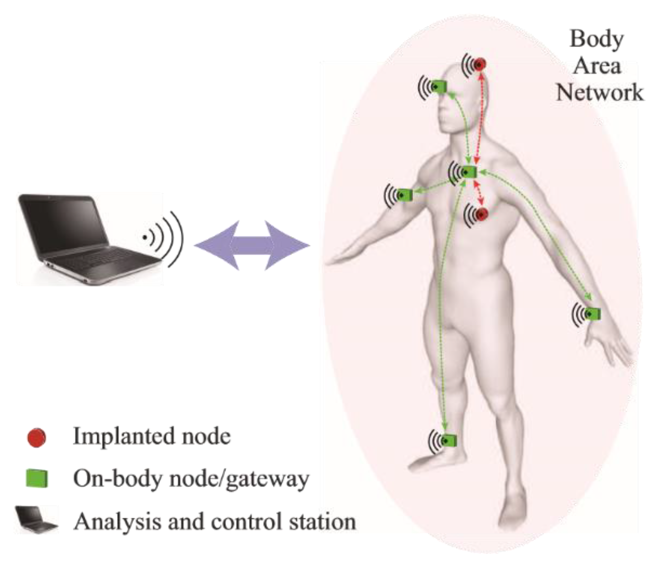
:1. Introduction
- Inter-node communication between various sensory nodes attached on the surface of the body
- Intra-node communication between a master node on the body and a transceiver off the body
- Implanted sensory nodes communicating with a node on the body (on-body node acting as a relay)
- Implanted sensory node communicating directly with a transceiver off the body.
- Fabric-based embroidered antennas
- Polymer-embedded antennas
- Microfluidic antennas with injection alloys
- Inkjet printing, screen printing and photolithography
- 3D-printed antennas
2. Fabric-Based Embroidered Antennas
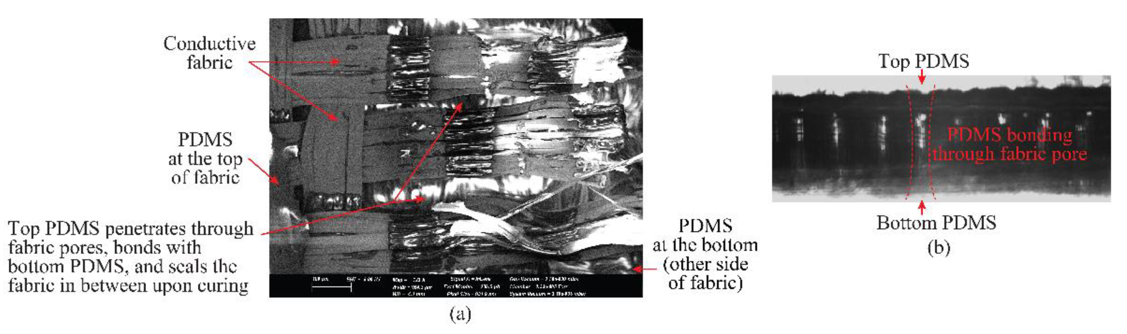
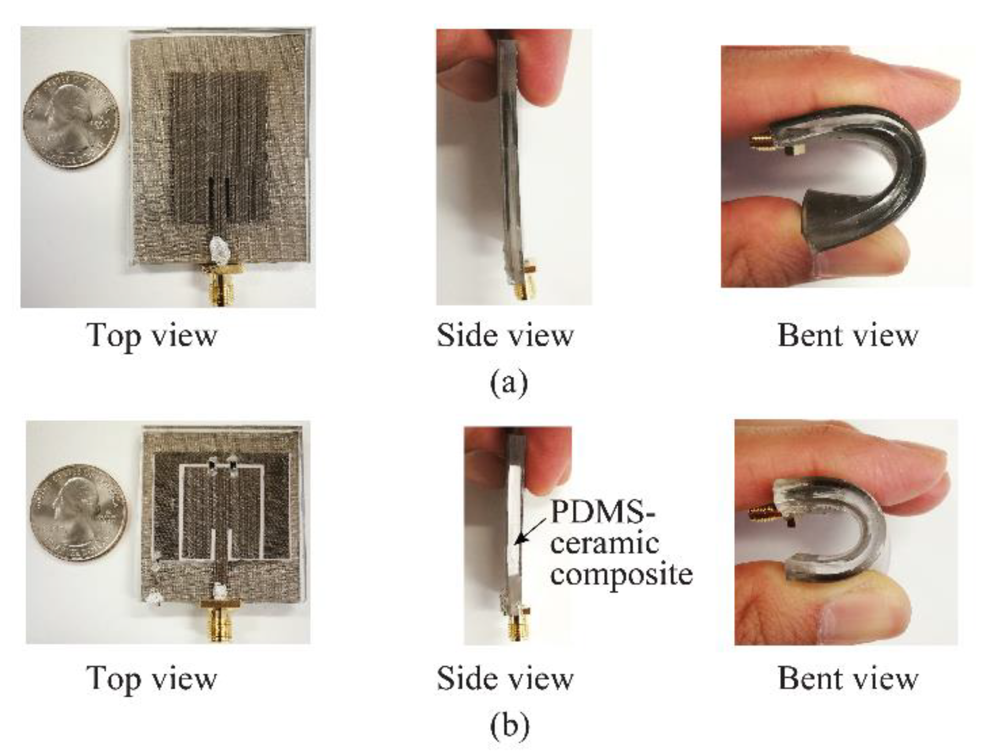
3. Polymer Embedded Antennas
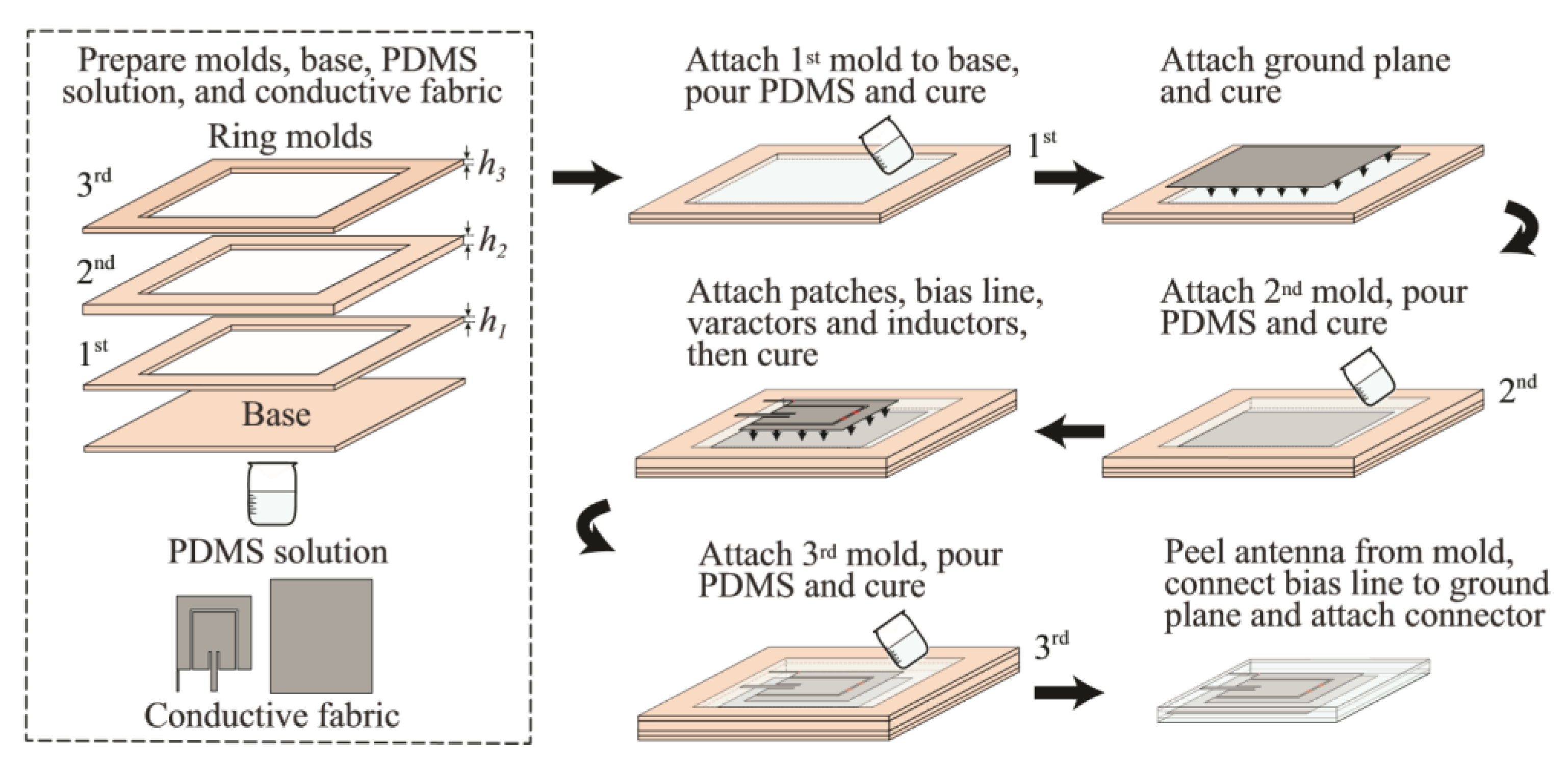
- Prepare the PDMS solution with the required permittivity and loss tangent, mold, base, and cut the conductive fabric manually following the dimensions of the antenna.
- Attach the first mold to the base with a silicone sealant, pour the PDMS solution into the mold, degas in a vacuum desiccator for approximately 30 min, and then cure in an oven at 65 °C for about 2 h.
- Attach the ground plane on top of the cured bottom encapsulation layer with a thin uncured PDMS solution, repel the bubbles occurring between them, and cure in the oven at 75 °C 20 min.
- Repeat Step 2 with the second mold to make the middle PDMS layer.
- Repeat Step 3 for the main patch.
- Repeat Step 2 with the third mold to make the top encapsulation layer.
- Carefully peel the prototype from the mold. If necessary, trim the excess PDMS layers from the edges of the antenna.
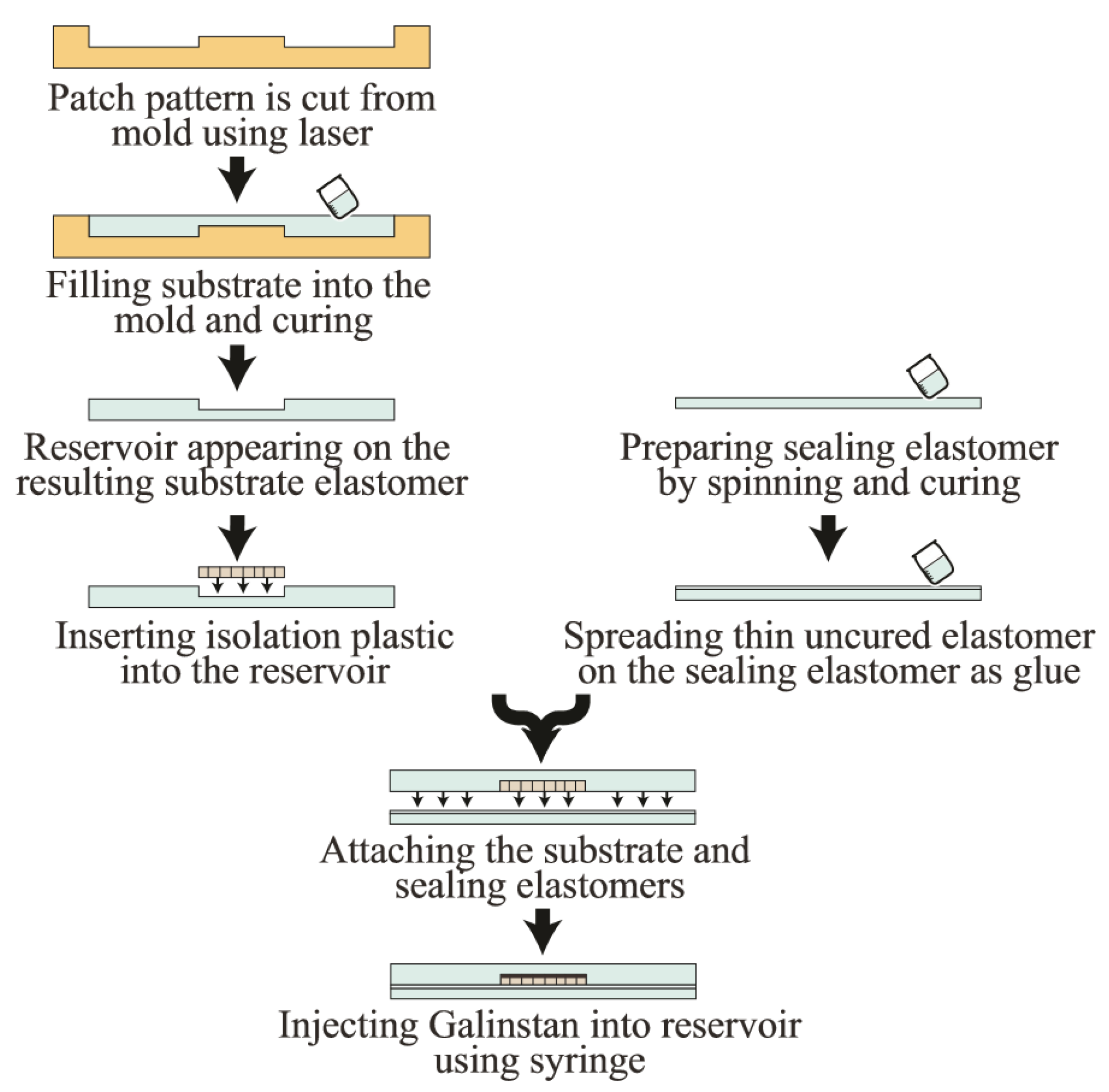
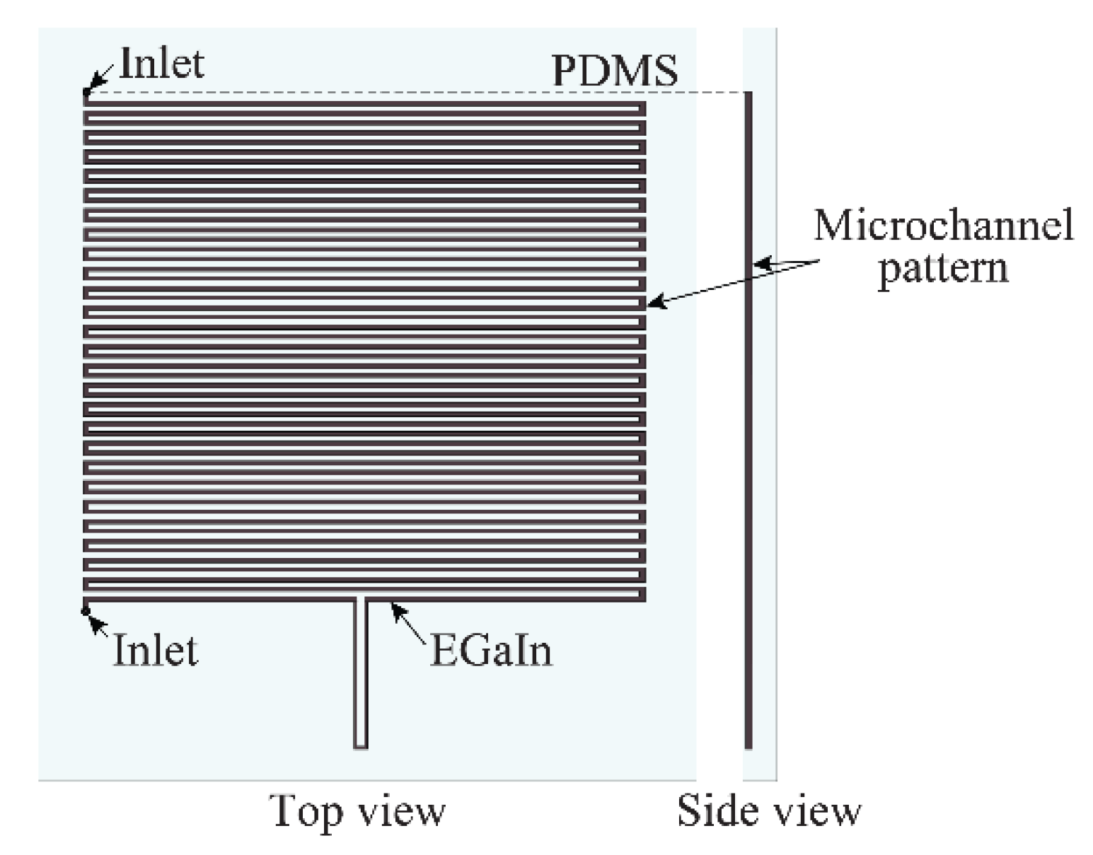
4. Microfluidic Antennas with Injection Alloys
5. Inkjet Printing, Screen Printing, and Photolithography
6. 3D-Printed Antennas
7. Fabrication Techniques for Future Wearable Millimeter-Wave Antennas
8. Human-Tissue-Equivalent Phantoms
9. Conclusions and Future Research Directions
- Development of methods for human-tissue parameters extraction and body models at mm-wave and terahertz frequencies in order to develop accurate and practical mm-wave antennas.
- Improving the efficiency and precision of the current manufacturing techniques, especially in higher-frequency bands.
- Improving methods of fabrication for microchannels in antennas based on injecting alloys.
- Introducing new flexible materials as a substrate with a wider range of permittivity for the embedding technique.
- Introducing new conductive fabrics and threads in the market with higher conductivity or less resistivity.
Conflicts of Interest
References
- Abbasi, M.A.B.; Nikolaou, S.S.; Antoniades, M.A.; Stevanovi´c, M.N.; Vryonides, P. Compact EBG-backed planar monopole for BAN wearable applications. IEEE Trans. Antennas Propag. 2017, 65, 453–463. [Google Scholar] [CrossRef]
- El Hajj, W.; Person, C.; Wiart, J. A Novel Investigation of a Broadband Integrated Inverted-F Antenna Design; Application for Wearable Antenna. IEEE Trans. Antennas Propag. 2014, 62, 3843–3846. [Google Scholar] [CrossRef]
- Yan, S.; Volskiy, V.; VandenBosch, G.A.E. Compact Dual-Band Textile PIFA for 433-MHz/2.4-GHz ISM Bands. IEEE Antennas Wirel. Propag. Lett. 2017, 16, 2436–2439. [Google Scholar] [CrossRef]
- Gao, G.; Hu, B.; Wang, S.; Yang, C. Wearable planar inverted-F antenna with stable characteristic and low specific absorption rate. Microw. Opt. Technol. Lett. 2018, 60, 876–882. [Google Scholar] [CrossRef]
- Michel, A.; Colella, R.; Casula, G.A.; Nepa, P.; Catarinucci, L.; Montisci, G.; Mazzarella, G.; Manara, G. Design Considerations on the Placement of a Wearable UHF-RFID PIFA on a Compact Ground Plane. IEEE Trans. Antennas Propag. 2018, 66, 3142–3147. [Google Scholar] [CrossRef]
- Owadally, A.; Parini, C.G.; Nechayev, Y.; Constantinou, C.C.; Hall, P.S.; Alomainy, A.; Hao, Y. Statistical Analysis and Performance Evaluation for On-Body Radio Propagation with Microstrip Patch Antennas. IEEE Trans. Antennas Propag. 2007, 55, 245–248. [Google Scholar]
- Yan, S.; Soh, P.J.; VandenBosch, G.A.E. Wearable Dual-Band Magneto-Electric Dipole Antenna for WBAN/WLAN Applications. IEEE Trans. Antennas Propag. 2015, 63, 1. [Google Scholar] [CrossRef]
- Moro, R.; Agneessens, S.; Rogier, H.; Dierck, A.; Bozzi, M. Textile Microwave Components in Substrate Integrated Waveguide Technology. IEEE Trans. Microw. Theory Tech. 2015, 63, 422–432. [Google Scholar] [CrossRef] [Green Version]
- Moro, R.; Agneessens, S.; Rogier, H.; Bozzi, M. Circularly-polarised cavity-backed wearable antenna in SIW technology. IET Microw. Antennas Propag. 2018, 12, 127–131. [Google Scholar] [CrossRef] [Green Version]
- Ashyap, A.Y.; Abidin, Z.; Dahlan, S.H.; Majid, H.A.; Shah, S.; Kamarudin, M.R.; Alomainy, A. Compact and Low-Profile Textile EBG-Based Antenna for Wearable Medical Applications. IEEE Antennas Wirel. Propag. Lett. 2017, 16, 1. [Google Scholar] [CrossRef]
- Islam, M.R.; Ali, M. A 900 MHz Beam Steering Parasitic Antenna Array for Wearable Wireless Applications. IEEE Trans. Antennas Propag. 2013, 61, 4520–4527. [Google Scholar] [CrossRef]
- Pinapati, S.P.; Ranasinghe, D.C.; Fumeaux, C. Textile Multi-Layer Cavity Slot-Monopole for UHF Applications. IEEE Antennas Wirel. Propag. Lett. 2017, 16, 1. [Google Scholar] [CrossRef]
- Chahat, N.; Zhadobov, M.; Le Coq, L.; Sauleau, R. Wearable Endfire Textile Antenna for On-Body Communications at 60 GHz. IEEE Antennas Wirel. Propag. Lett. 2012, 11, 799–802. [Google Scholar] [CrossRef]
- Sabri, S.F.; Sam, S.M.; Kamardin, K.; Daud, S.M.; Salleh, N. Review of the Current Design on Wearable Antenna in Medical Field and its Challenges. J. Teknol. 2016, 78, 111–117. [Google Scholar] [CrossRef]
- Gupta, B.; Sankaralingam, S.; Dhar, S. Development of wearable and implantable antennas in the last decade: A review. In Proceedings of the 2010 10th Mediterranean Microwave Symposium, Guzelyurt, Cyprus, 25–27 August 2010. [Google Scholar]
- Roh, J.S.; Chi, Y.S.; Kang, T.J. Wearable textile antennas. Int. J. Fash. Des. Technol. Edu. 2010, 3, 135–153. [Google Scholar] [CrossRef]
- Wang, J.C.; Lim, E.G.; Leach, M.; Wang, Z.; Man, K.L.; Huang, Y. Review of wearable antennas for WBAN applications. IAENG Int. J. Comput. Sci. 2016, 43, 16–19. [Google Scholar]
- Yan, S.; Soh, P.J.; VandenBosch, G.A.E. Wearable Ultrawideband Technology—A Review of Ultrawideband Antennas, Propagation Channels, and Applications in Wireless Body Area Networks. IEEE Access 2018, 6, 42177–42185. [Google Scholar] [CrossRef]
- Nepa, P.; Rogier, H. Wearable Antennas for Off-Body Radio Links at VHF and UHF Bands: Challenges, the state of the art, and future trends below 1 GHz. IEEE Antennas Propag. Mag. 2015, 57, 30–52. [Google Scholar] [CrossRef]
- Wang, Z.; Zhang, L.; Volakis, J.L. Textile antennas for wearable radio frequency applications. Text. Light Indust. Sci. Technol. 2013, 2, 105–112. [Google Scholar]
- Priya, A.; Kumar, A.; Chauhan, B. A Review of Textile and Cloth Fabric Wearable Antennas. Int. J. Comput. Appl. 2015, 116, 1–5. [Google Scholar] [CrossRef]
- Stoppa, M.; Chiolerio, A. Wearable Electronics and Smart Textiles: A Critical Review. Sensors 2014, 14, 11957–11992. [Google Scholar] [CrossRef] [PubMed] [Green Version]
- Dhupkariya, S.; Singh, V.K.; Shukla, A. A review of textile materials for wearable antenna. J. Microw. Eng. Technol. 2015, 1, 1–8. [Google Scholar]
- Zeng, W.; Shu, L.; Li, Q.; Chen, S.; Wang, F.; Tao, X.-M. Fiber-Based Wearable Electronics: A Review of Materials, Fabrication, Devices, and Applications. Adv. Mater. 2014, 26, 5310–5336. [Google Scholar] [CrossRef] [PubMed]
- Tsolis, A.; Whittow, W.G.; Alexandridis, A.A.; Vardaxoglou, J.C. Embroidery and Related Manufacturing Techniques for Wearable Antennas: Challenges and Opportunities. Electronics 2014, 3, 314–338. [Google Scholar] [CrossRef] [Green Version]
- Salvado, R.; Loss, C.; Gonçalves, R.; Pinho, P. Textile Materials for the Design of Wearable Antennas: A Survey. Sensors 2012, 12, 15841–15857. [Google Scholar] [CrossRef] [Green Version]
- Zhang, L.; Wang, Z.; Volakis, J.L. Textile Antennas and Sensors for Body-Worn Applications. IEEE Antennas Wirel. Propag. Lett. 2012, 11, 1690–1693. [Google Scholar] [CrossRef]
- Sankaralingam, S.; Gupta, B. Determination of Dielectric Constant of Fabric Materials and Their Use as Substrates for Design and Development of Antennas for Wearable Applications. IEEE Trans. Instrum. Meas. 2010, 59, 3122–3130. [Google Scholar] [CrossRef]
- Seager, R.; Dias, T.; Zhang, S.; Acti, T.; Vardaxoglou, Y.; Whittow, W.; Chauraya, A.; Seager, R. Effect of the fabrication parameters on the performance of embroidered antennas. IET Microwaves, Antennas Propag. 2013, 7, 1174–1181. [Google Scholar] [CrossRef] [Green Version]
- Kiourti, A.; Volakis, J.L. High-Geometrical-Accuracy Embroidery Process for Textile Antennas With Fine Details. IEEE Antennas Wirel. Propag. Lett. 2015, 14, 1474–1477. [Google Scholar] [CrossRef]
- Simorangkir, R.B.V.B.; Yang, Y.; Esselle, K.P. Double-layer embroidery strategy for fabrication of textile antennas with improved efficiency. In Proceedings of the 2016 17th International Symposium on Antenna Technology and Applied Electromagnetics (ANTEM), Montreal, QC, Canada, 10–13 July 2016. [Google Scholar]
- Ouyang, Y.; Chappell, W. High Frequency Properties of Electro-Textiles for Wearable Antenna Applications. IEEE Trans. Antennas Propag. 2008, 56, 381–389. [Google Scholar] [CrossRef]
- Tak, J.; Choi, J.; Lee, S. All-textile higher order mode circular patch antenna for on-body to on-body communications. IET Microwaves, Antennas Propag. 2015, 9, 576–584. [Google Scholar] [CrossRef]
- Kiourti, A.; Lee, C.; Volakis, J.L. Fabrication of Textile Antennas and Circuits With 0.1 mm Precision. IEEE Antennas Wirel. Propag. Lett. 2016, 15, 151–153. [Google Scholar] [CrossRef]
- Zhong, J.; Kiourti, A.; Sebastian, T.; Bayram, Y.; Volakis, J.L. Conformal Load-Bearing Spiral Antenna on Conductive Textile Threads. IEEE Antennas Wirel. Propag. Lett. 2017, 16, 230–233. [Google Scholar] [CrossRef]
- Roh, J.-S.; Chi, Y.-S.; Lee, J.-H.; Tak, Y.; Nam, S.; Kang, T.J. Embroidered Wearable Multiresonant Folded Dipole Antenna for FM Reception. IEEE Antennas Wirel. Propag. Lett. 2010, 9, 803–806. [Google Scholar] [CrossRef]
- Wang, Z.; Lee, L.Z.; Psychoudakis, D.; Volakis, J.L. Embroidered Multiband Body-Worn Antenna for GSM/PCS/WLAN Communications. IEEE Trans. Antennas Propag. 2014, 62, 3321–3329. [Google Scholar] [CrossRef]
- Ivsic, B.; Bonefacic, D.; Bartolic, J. Considerations on Embroidered Textile Antennas for Wearable Applications. IEEE Antennas Wirel. Propag. Lett. 2013, 12, 1708–1711. [Google Scholar] [CrossRef]
- Simorangkir, R.B.V.B.; Yang, Y.; Esselle, K.P. Performance of embroidered higher-order mode antennas with different stitching patterns. In Proceedings of the 2017 11th European Conference on Antennas and Propagation (EUCAP), Paris, France, 19–24 March 2017. [Google Scholar]
- Moradi, E.; Björninen, T.; Ukkonen, L.; Rahmat-Samii, Y. Effects of Sewing Pattern on the Performance of Embroidered Dipole-Type RFID Tag Antennas. IEEE Antennas Wirel. Propag. Lett. 2012, 11, 1482–1485. [Google Scholar] [CrossRef]
- Wang, Z.; Zhang, L.; Bayram, Y.; Volakis, J.L. Embroidered Conductive Fibers on Polymer Composite for Conformal Antennas. IEEE Trans. Antennas Propag. 2012, 60, 4141–4147. [Google Scholar] [CrossRef]
- Zhang, S.; Whittow, W.; Seager, R.; Chauraya, A.; Vardaxoglou, J.C. Non-uniform mesh for embroidered microstrip antennas. IET Microwaves, Antennas Propag. 2017, 11, 1086–1091. [Google Scholar] [CrossRef] [Green Version]
- Koski, K.; Vena, A.; Sydanheimo, L.; Ukkonen, L.; Rahmat-Samii, Y. Design and Implementation of Electro-Textile Ground Planes for Wearable UHF RFID Patch Tag Antennas. IEEE Antennas Wirel. Propag. Lett. 2013, 12, 964–967. [Google Scholar] [CrossRef]
- Alharbi, S.; Chaudhari, S.; Inshaar, A.; Shah, H.; Zou, C.; Harne, R.L.; Kiourti, A. E-Textile Origami Dipole Antennas with Graded Embroidery for Adaptive RF Performance. IEEE Antennas Wirel. Propag. Lett. 2018, 17, 2218–2222. [Google Scholar] [CrossRef]
- Lilja, J.; Salonen, P.; Kaija, T.; De Maagt, P. Design and Manufacturing of Robust Textile Antennas for Harsh Environments. IEEE Trans. Antennas Propag. 2012, 60, 4130–4140. [Google Scholar] [CrossRef]
- Trajkovikj, J.; Zürcher, J.F.; Skrivervik, A.K. PDMS, a robust casing for flexible W-BAN antennas [EurAAP Corner]. IEEE Antennas Propag. Mag. 2013, 55, 287–297. [Google Scholar] [CrossRef]
- Abbasi, Q.H.; Rehman, M.U.; Yang, X.; Alomainy, A.; Qaraqe, K.; Serpedin, E. Ultrawideband Band-Notched Flexible Antenna for Wearable Applications. IEEE Antennas Wirel. Propag. Lett. 2013, 12, 1606–1609. [Google Scholar] [CrossRef]
- Zhou, Y.; Bayram, Y.; Du, F.; Dai, L.; Volakis, J.L. Polymer-Carbon Nanotube Sheets for Conformal Load Bearing Antennas. IEEE Trans. Antennas Propag. 2010, 58, 2169–2175. [Google Scholar] [CrossRef]
- Song, L.; Myers, A.C.; Adams, J.J.; Zhu, Y. Stretchable and Reversibly Deformable Radio Frequency Antennas Based on Silver Nanowires. ACS Appl. Mater. Interfaces 2014, 6, 4248–4253. [Google Scholar] [CrossRef]
- Huang, G.W.; Xiao, H.M.; Fu, S.Y. Wearable electronics of silvernanowire/poly (dimethylsiloxane) nanocomposite for smart clothing. Sci. Rep. 2015, 5, 13971. [Google Scholar] [CrossRef] [PubMed]
- Kiourti, A.; Volakis, J.L. Stretchable and Flexible E-Fiber Wire Antennas Embedded in Polymer. IEEE Antennas Wirel. Propag. Lett. 2014, 13, 1381–1384. [Google Scholar] [CrossRef]
- Simorangkir, R.B.V.B.; Yang, Y.; Esselle, K.P.; Zeb, B.A. A Method to Realize Robust Flexible Electronically Tunable Antennas Using Polymer-Embedded Conductive Fabric. IEEE Trans. Antennas Propag. 2018, 66, 50–58. [Google Scholar] [CrossRef]
- Simorangkir, R.; Yang, Y.; Esselle, K. Robust Implementation of Flexible Wearable Antennas with PDMS-Embedded Conductive Fabric. In Proceedings of the 12th European Conference on Antennas and Propagation (EuCAP 2018), London, UK, 9–13 April 2018. [Google Scholar]
- Garg, R.; Bhartia, P.; Bahl, I.J.; Ittipiboon, A. Rectangular microstrip antennas. In Microstrip Antenna Design Handbook; Artech House: Norwood, MA, USA, 2001; p. 265. [Google Scholar]
- Zhou, W.-Y.; Qi, S.-H.; Zhao, H.-Z.; Liu, N.-L. Thermally conductive silicone rubber reinforced with boron nitride particle. Polym. Compos. 2007, 28, 23–28. [Google Scholar] [CrossRef]
- Alqadami, A.S.M.; Jamlos, M.F.; Soh, P.J.; VandenBosch, G.A.E. Assessment of PDMS Technology in a MIMO Antenna Array. IEEE Antennas Wirel. Propag. Lett. 2016, 15, 1. [Google Scholar] [CrossRef]
- Simorangkir, R.B.V.B.; Matekovits, L.; Esselle, K.; Yang, Y. Dual-Band Dual-Mode Textile Antenna on PDMS Substrate for Body-Centric Communications. IEEE Antennas Wirel. Propag. Lett. 2017, 16, 1. [Google Scholar] [CrossRef]
- Cresson, P.-Y.; Orlic, Y.; Legier, J.-F.; Paleczny, E.; Dubois, L.; Tiercelin, N.; Coquet, P.; Pernod, P.; Lasri, T. 1 to 220 GHz Complex Permittivity Behavior of Flexible Polydimethylsiloxane Substrate. IEEE Microw. Wirel. Components Lett. 2014, 24, 278–280. [Google Scholar] [CrossRef]
- Jang, T.; Zhang, C.; Youn, H.; Zhou, J.; Guo, L.J. Semitransparent and Flexible Mechanically Reconfigurable Electrically Small Antennas Based on Tortuous Metallic Micromesh. IEEE Trans. Antennas Propag. 2017, 65, 150–158. [Google Scholar] [CrossRef]
- Simorangkir, R.B.V.B.; Yang, Y.; Hashmi, R.M.; Bjorninen, T.; Esselle, K.P.; Ukkonen, L. Polydimethylsiloxane-Embedded Conductive Fabric: Characterization and Application for Realization of Robust Passive and Active Flexible Wearable Antennas. IEEE Access 2018, 6, 48102–48112. [Google Scholar] [CrossRef]
- So, J.-H.; Thelen, J.; Qusba, A.; Hayes, G.J.; Lazzi, G.; Dickey, M.D. Reversibly Deformable and Mechanically Tunable Fluidic Antennas. Adv. Funct. Mater. 2009, 19, 3632–3637. [Google Scholar] [CrossRef] [Green Version]
- Mazlouman, S.J.; Jiang, X.J.; Mahanfar, A.; Menon, C.; Vaughan, R.G. A Reconfigurable Patch Antenna Using Liquid Metal Embedded in a Silicone Substrate. IEEE Trans. Antennas Propag. 2011, 59, 4406–4412. [Google Scholar] [CrossRef]
- Cheng, S.; Wu, Z.; Hallbjorner, P.; Hjort, K.; Rydberg, A. Foldable and Stretchable Liquid Metal Planar Inverted Cone Antenna. IEEE Trans. Antennas Propag. 2009, 57, 3765–3771. [Google Scholar] [CrossRef]
- Hayes, G.J.; So, J.-H.; Qusba, A.; Dickey, M.D.; Lazzi, G. Flexible Liquid Metal Alloy (EGaIn) Microstrip Patch Antenna. IEEE Trans. Antennas Propag. 2012, 60, 2151–2156. [Google Scholar] [CrossRef]
- Cosker, M.; Lizzi, L.; Ferrero, F.; Staraj, R.; Ribero, J.-M. Realization of 3D Flexible Antennas using Liquid Metal and Additive Printing Technologies. IEEE Antennas Wirel. Propag. Lett. 2017, 16, 1. [Google Scholar] [CrossRef]
- Khaleel, H.R. Design and Fabrication of Compact Inkjet Printed Antennas for Integration Within Flexible and Wearable Electronics. IEEE Trans. Components, Packag. Manuf. Technol. 2014, 4, 1722–1728. [Google Scholar] [CrossRef]
- Rizwan, M.; Virkki, J.; Ukkonen, L.; Khan, M.W.A.; Sydanheimo, L. Flexible and Stretchable Brush-Painted Wearable Antenna on a Three-Dimensional (3-D) Printed Substrate. IEEE Antennas Wirel. Propag. Lett. 2017, 16, 3108–3112. [Google Scholar] [CrossRef]
- Scarpello, M.L.; Kazani, I.; Hertleer, C.; Rogier, H.; Ginste, D.V. Stability and Efficiency of Screen-Printed Wearable and Washable Antennas. IEEE Antennas Wirel. Propag. Lett. 2012, 11, 838–841. [Google Scholar] [CrossRef]
- Li, X.; Honari, M.M.; Fu, Y.; Kumar, A.; Saghlatoon, H.; Mousavi, P.; Chung, H.-J. Self-reinforcing graphene coatings on 3D printed elastomers for flexible radio frequency antennas and strain sensors. Flex. Print. Electron. 2017, 2, 035001. [Google Scholar] [CrossRef]
- Nikolaou, S.; Ponchak, G.; Papapolymerou, J.; Tentzeris, M. Conformal Double Exponentially Tapered Slot Antenna (DETSA) on LCP for UWB Applications. IEEE Trans. Antennas Propag. 2006, 54, 1663–1669. [Google Scholar] [CrossRef] [Green Version]
- Genovesi, S.; Costa, F.; Fanciulli, F.; Monorchio, A. Wearable Inkjet-Printed Wideband Antenna by using Miniaturized AMC for Sub-GHz Applications. IEEE Antennas Wirel. Propag. Lett. 2016, 15, 1. [Google Scholar] [CrossRef]
- Chauraya, A.; Tudor, J.; Vardaxoglou, J.C.; Torah, R.; Li, Y.; Whittow, W.G.; Beeby, S.; Yang, K.; Beeby, S. Inkjet printed dipole antennas on textiles for wearable communications. IET Microwaves, Antennas Propag. 2013, 7, 760–767. [Google Scholar] [CrossRef] [Green Version]
- Durgun, A.C.; Balanis, C.A.; Birtcher, C.R.; Allee, D.R. Design, Simulation, Fabrication and Testing of Flexible Bow-Tie Antennas. IEEE Trans. Antennas Propag. 2011, 59, 4425–4435. [Google Scholar] [CrossRef]
- Lakafosis, V.; Rida, A.; Vyas, R.; Yang, L.; Nikolaou, S.; Tentzeris, M.M. Progress Towards the First Wireless Sensor Networks Consisting of Inkjet-Printed, Paper-Based RFID-Enabled Sensor Tags. Proc. IEEE 2010, 98, 1601–1609. [Google Scholar] [CrossRef] [Green Version]
- Saeed, S.M.; Balanis, C.A.; Birtcher, C.R. Inkjet-printed flexible reconfigurable antenna for conformal WLAN/WiMAX wireless devices. IEEE Antennas Wirel. Propag. Lett. 2016, 15, 1979–1982. [Google Scholar] [CrossRef]
- Amendola, S.; Palombi, A.; Marrocco, G. Inkjet Printing of Epidermal RFID Antennas by Self-Sintering Conductive Ink. IEEE Trans. Microw. Theory Tech. 2018, 66, 1561–1569. [Google Scholar] [CrossRef]
- Ahmed, S.; Tahir, F.A.; Shamim, A.; Cheema, H.M. A Compact Kapton-based Inkjet Printed Multiband Antenna for Flexible Wireless Devices. IEEE Antennas Wirel. Propag. Lett. 2015, 14, 1. [Google Scholar] [CrossRef]
- Abutarboush, H.F.; Farooqui, M.F.; Shamim, A. Inkjet-printed wideband antenna on resin-coated paper substrate for curved wireless devices. IEEE Antennas Wirel. Propag. Lett. 2016, 15, 20–23. [Google Scholar] [CrossRef]
- Li, Y.; Torah, R.; Beeby, S.; Tudor, J. An all-inkjet printed flexible capacitor on a textile using a new poly(4-vinylphenol) dielectric ink for wearable applications. In Proceedings of the 2012 IEEE Sensors, Taipei, Taiwan, 28–31 October 2012. [Google Scholar] [CrossRef]
- Thielens, A.; Deckman, I.; Aminzadeh, R.; Arias, A.C.; Rabaey, J.M. Fabrication and Characterization of Flexible Spray-Coated Antennas. IEEE Access 2018, 6, 62050–62061. [Google Scholar] [CrossRef]
- Jilani, S.F.; Abbasi, Q.H.; Alomainy, A. Inkjet-Printed Millimetre-Wave PET-Based Flexible Antenna for 5G Wireless Applications. In Proceedings of the 2018 IEEE MTT-S International Microwave Workshop Series on 5G Hardware and System Technologies (IMWS-5G), Dublin, Ireland, 30–31 August 2018. [Google Scholar]
- Whittow, W.G.; Chauraya, A.; Vardaxoglou, J.C.; Li, Y.; Torah, R.; Yang, K.; Beeby, S.; Tudor, J. Inkjet-Printed Microstrip Patch Antennas Realized on Textile for Wearable Applications. IEEE Antennas Wirel. Propag. Lett. 2014, 13, 71–74. [Google Scholar] [CrossRef] [Green Version]
- Le, T.; Song, B.; Liu, Q.; Bahr, R.A.; Moscato, S.; Wong, C.-P.; Tentzeris, M.M. A novel strain sensor based on 3D printing technology and 3D antenna design. In Proceedings of the 2015 IEEE 65th Electronic Components and Technology Conference (ECTC), San Diego, CA, USA, 26–29 May 2015; pp. 981–986. [Google Scholar]
- Moscato, S.; Bahr, R.; Le, T.; Pasian, M.; Bozzi, M.; Perregrini, L.; Tentzeris, M.M.; Tentzeris, E. Infill Dependent 3D-Printed Material Based on NinjaFlex Filament for Antenna Applications. IEEE Antennas Wirel. Propag. Lett. 2016, 15, 1. [Google Scholar] [CrossRef]
- Adams, J.J.; Duoss, E.B.; Malkowski, T.F.; Motala, M.J.; Ahn, B.Y.; Nuzzo, R.G.; Bernhard, J.T.; Lewis, J.A. Conformal Printing of Electrically Small Antennas on Three-Dimensional Surfaces. Adv. Mater. 2011, 23, 1335–1340. [Google Scholar] [CrossRef] [PubMed]
- Ota, H.; Emaminejad, S.; Gao, Y.; Zhao, A.; Wu, E.; Challa, S.; Chen, K.; Fahad, H.M.; Jha, A.K.; Kiriya, D.; et al. Application of 3D Printing for Smart Objects with Embedded Electronic Sensors and Systems. Adv. Mater. Technol. 2016, 1, 1600013. [Google Scholar] [CrossRef] [Green Version]
- Nate, K.; Tentzeris, M.M. A novel 3-D printed loop antenna using flexible NinjaFlex material for wearable and IoT applications. In Proceedings of the 2015 IEEE 24th Electrical Performance of Electronic Packaging and Systems (EPEPS), San Jose, CA, USA, 25–28 October 2015; pp. 171–174. [Google Scholar]
- He, H.; Akbari, M.; Sydänheimo, L.; Ukkonen, L.; Virkki, J.; Sydä Nheimo, L. 3D-Printed Graphene Antennas and Interconnections for Textile RFID Tags: Fabrication and Reliability towards Humidity. Int. J. Antennas Propag. 2017, 2017, 1–5. [Google Scholar] [CrossRef] [Green Version]
- Ur-Rehman, M.; Malik, N.A.; Yang, X.; Abbasi, Q.H.; Zhang, Z.; Zhao, N. A Low Profile Antenna for Millimeter-Wave Body-Centric Applications. IEEE Trans. Antennas Propag. 2017, 65, 6329–6337. [Google Scholar] [CrossRef] [Green Version]
- Pellegrini, A.; Brizzi, A.; Zhang, L.; Ali, K.; Hao, Y.; Wu, X.; Constantinou, C.C.; Nechayev, Y.; Hall, P.S.; Chahat, N.; et al. Antennas and Propagation for Body-Centric Wireless Communications at Millimeter-Wave Frequencies: A Review [Wireless Corner]. IEEE Antennas Propag. Mag. 2013, 55, 262–287. [Google Scholar] [CrossRef]
- Chahat, N.; Valerio, G.; Zhadobov, M.; Sauleau, R. On-body propagation at 60 GHz. IEEE Trans. Antennas Propag. 2013, 61, 1876–1888. [Google Scholar] [CrossRef]
- Guraliuc, A.R.; Zhadobov, M.; Valerio, G.; Chahat, N.; Sauleau, R. Effect of Textile on the Propagation Along the Body at 60 GHz. IEEE Trans. Antennas Propag. 2014, 62, 1489–1494. [Google Scholar] [CrossRef]
- Chahat, N.; Zhadobov, M.; Le Coq, L.; Alekseev, S.I.; Sauleau, R. Characterization of the Interactions Between a 60-GHz Antenna and the Human Body in an Off-Body Scenario. IEEE Trans. Antennas Propag. 2012, 60, 5958–5965. [Google Scholar] [CrossRef]
- Chahat, N.; Zhadobov, M.; Muhammad, S.A.; Le Coq, L.; Sauleau, R. 60-GHz Textile Antenna Array for Body-Centric Communications. IEEE Trans. Antennas Propag. 2013, 61, 1816–1824. [Google Scholar] [CrossRef]
- Tehrani, B.K.; Cook, B.S.; Tentzeris, M.M. Inkjet Printing of Multilayer Millimeter-Wave Yagi-Uda Antennas on Flexible Substrates. IEEE Antennas Wirel. Propag. Lett. 2016, 15, 1. [Google Scholar] [CrossRef]
- Jilani, S.F.; Munoz, M.O.; Abbasi, Q.H.; Alomainy, A.; Torrico, M.M.; Abbasi, Q. Millimeter-Wave Liquid Crystal Polymer Based Conformal Antenna Array for 5G Applications. IEEE Antennas Wirel. Propag. Lett. 2019, 18, 84–88. [Google Scholar] [CrossRef]
- Hage-Ali, S.; Tiercelin, N.; Coquet, P.; Sauleau, R.; Fujita, H.; Preobrazhensky, V.; Pernod, P. A Millimeter-Wave Microstrip Antenna Array on Ultra-Flexible Micromachined Polydimethylsiloxane (PDMS) Polymer. IEEE Antennas Wirel. Propag. Lett. 2009, 8, 1306–1309. [Google Scholar] [CrossRef]
- LeDuc, C.; Zhadobov, M. Impact of Antenna Topology and Feeding Technique on Coupling with Human Body: Application to 60-GHz Antenna Arrays. IEEE Trans. Antennas Propag. 2017, 65, 6779–6787. [Google Scholar] [CrossRef]
- Chen, W.-T.; Chuang, H.-R. Numerical computation of human interaction with arbitrarily oriented superquadric loop antennas in personal communications. IEEE Trans. Antennas Propag. 1998, 46, 821–828. [Google Scholar] [CrossRef]
- Johnson, C.; Guy, A. Nonionizing electromagnetic wave effects in biological materials and systems. Proc. IEEE 1972, 60, 692–718. [Google Scholar] [CrossRef]
- Watanabe, S.-I.; Taki, H.; Nojima, T.; Fujiwara, O. Characteristics of the SAR distributions in a head exposed to electromagnetic fields radiated by a hand-held portable radio. IEEE Trans. Microw. Theory Tech. 1996, 44, 1874–1883. [Google Scholar] [CrossRef]
- Gabriel, C. Tissue equivalent material for hand phantoms. Phys. Med. Boil. 2007, 52, 4205–4210. [Google Scholar] [CrossRef] [PubMed]
- Gabriel, S.; Lau, R.W.; Gabriel, C. The dielectric properties of biological tissues: III. Parametric models for the dielectric spectrum of tissues. Phys. Med. Boil. 1996, 41, 2271–2293. [Google Scholar] [CrossRef]
- Lazebnik, M.; McCartney, L.; Popovic, D.; Watkins, C.B.; Lindstrom, M.J.; Harter, J.; Sewall, S.; Magliocco, A.; Booske, J.H.; Okoniewski, M.; et al. A large-scale study of the ultrawideband microwave dielectric properties of normal breast tissue obtained from reduction surgeries. Phys. Med. Boil. 2007, 52, 2637–2656. [Google Scholar] [CrossRef] [PubMed]
- Takimoto, T.; Onishi, T.; Saito, K.; Takahashi, M.; Uebayashi, S.; Ito, K. Characteristics of biological tissue equivalent phantoms applied to UWB communications. Electron. Commun. Part I Commun. 2007, 90, 48–55. [Google Scholar] [CrossRef]
- Kobayashi, T.; Nojima, T.; Yamada, K.; Uebayashi, S. Dry phantom composed of ceramics and its application to SAR estimation. IEEE Trans. Microw. Theory Tech. 1993, 41, 136–140. [Google Scholar] [CrossRef]
- Ito, K.; Furuya, K.; Okano, Y.; Hamada, L. Development and characteristics of a biological tissue-equivalent phantom for microwaves. Electron. Commun. Part I Commun. 2001, 84, 67–77. [Google Scholar] [CrossRef]
- Mobashsher, A.T.; Abbosh, A.M. Artificial Human Phantoms: Human Proxy in Testing Microwave Apparatuses That Have Electromagnetic Interaction with the Human Body. IEEE Microw. Mag. 2015, 16, 42–62. [Google Scholar] [CrossRef] [Green Version]
- Hartsgrove, G.; Kraszewski, A.; Surowiec, A. Simulated biological materials for electromagnetic radiation absorption studies. Bioelectromagnetics 1987, 8, 29–36. [Google Scholar] [CrossRef]
- Mashal, A.; Gao, F.; Hagness, S.C. Heterogeneous Anthropomorphic Phantoms with Realistic Dielectric Properties for Microwave Breast Imaging Experiments. Microw. Opt. Technol. Lett. 2011, 53, 1896–1902. [Google Scholar] [CrossRef] [PubMed] [Green Version]
- Yonebayashi, J.; Takamatsu, S.; Saito, K.; Takahashi, M.; Ito, K. Development of dynamic phantom for evaluation of breath detection doppler radar. In Proceedings of the 32nd Annual Meeting of the Bioelectromagnetics Society, Seoul, Korea, 13–18 June 2010. [Google Scholar]
- Lubecke, O.B.; Ong, P.W.; Lubecke, V.M. 10 GHz Doppler radar sensing of respiration and heart movement. In Proceedings of the IEEE 28th Annual Northeast Bioengineering Conference, Philadelphia, PA, USA, 21 April 2002; pp. 55–56. [Google Scholar]
- Song, R.; Wang, Q.; Mao, B.; Wang, Z.; Tang, D.; Zhang, B.; Zhang, J.; Liu, C.; He, D.; Wu, Z.; et al. Flexible graphite films with high conductivity for radio-frequency antennas. Carbon 2018, 130, 164–169. [Google Scholar] [CrossRef]
- Tang, D.; Wang, Q.; Wang, Z.; Liu, Q.; Zhang, B.; He, D.; Wu, Z.; Mu, S. Highly sensitive wearable sensor based on a flexible multi-layer graphene film antenna. Sci. Bull. 2018, 63, 574–579. [Google Scholar] [CrossRef]


| Frequency | Application |
|---|---|
| 401–402 MHz 402–405 MHz 403.5–403.8 MHz 405–406 MHz | Medical Implant Communication Services (MICS) |
| 413–457 MHz | Medradio Micropower Networks (MMN), transmit and relay data for implanted and body-worn medical devices for diagnostic and therapeutic functions |
| 2.4 & 5 GHz | Wi-Fi, smart hospital beds, mobile nursing stations |
| 2.404–2.478 GHz | Bluetooth, indoor navigation for patients, connectivity between device and smartphone for health-data monitoring |
| 2.36–2.4 GHz | New Medical BAN (MBAN) |
| New Medical BAN (MBAN) | Industrial, Scientific, and Medical (ISM) |
| 3.1–10.76 GHz | Ultra-Wideband (UWB) |
| 57–64 GHz 59–66 GHz | The band plans and rules at mmW-60 WBAN |
| Ref. | Conductor | Conductor | Substrate Material | Substrate | Substrate tan δ | Freq. (MHz) | Antenna Type |
|---|---|---|---|---|---|---|---|
| [36] | Metal Composite Embroidery Yarn (MCEY) | 3.88 Ω/m | Polyester woven | 1.15 | NA | 87.5–108 | Folded dipole |
| [37] | Silver-coated Amberstrand fibers | 0.75 Ω/m | NA | NA | NA | 900 (41.6%), 1900 (75.8%), 2450 (65.6%) | Patch |
| [41] | Silver-coated Amberstrand fiber | 0.8 Ω/m | PDMS | 4.2 | 0.01 | 2200 | Patch |
| [42] | Amberstrand Silver 66 | 6.5 Ω/m | Taconic RF-45 | 4.5 | 0.0037 | 2400 | Patch |
| [43] | Shieldex thread | NA | Cotton fabric | 1.8 | 0.018 | 900 | Patch |
| [44] | Elektrisola | 1.9 Ω/m | Organza | close to air | close to air | 760 (15%) | Dipole |
| Ref. | Conductor | Conductor σ or Rs | Substrate Material | Substrate | Substrate tan δ | Freq. (MHz) | Antenna Type |
|---|---|---|---|---|---|---|---|
| [48] | Carbon nanotube | 0.9 Ω/sq | PDMS | 3.8 | 0.015 | 2250 | Patch |
| [49] | Silver nanowires | 8.13 × 10³ S/m | PDMS | 2.67 | 0.01 | 2920 | Patch |
| [51] | Amberstrand fibers | 1.6–2.6 Ω/m | PDMS | 3 | 0.02 | 915 | Wire antenna |
| [56] | Copper foil | NA | PDMS | 2.7 | 0.013 | 5800 | Microstrip array |
| [57] | Nickel-copper-silver coated nylon | 0.01 Ω/sq | PDMS | 2.8 | 0.02, 0.04 | 2450 5800 | Patch |
| [59] | Copper micromesh | 3.28 × 10⁴ S/m | PDMS | 2.8 | 0.02 | 2460 to 2940 | Reconfigurable patch |
| Ref. | Conductor | Conductor σ | Substrate Material | Substrate | Substrate tan δ | Freq. (GHz) | Eff (%) | Antenna Type |
|---|---|---|---|---|---|---|---|---|
| [61] | EGaIn | 3.46 × 10⁴ S/m | PDMS | 2.67 | 0.0375 | 1.91–1.99 | 90 | Dipole |
| [62] | Galinstan | 3.46 × 10⁶ S/m | TC5005 | 2.8–3.1 | NA | 1.3–3 | 80 | Reconfigurable patch |
| [63] | Galinstan | 3.46 × 10⁶ S/m | PDMS | 3 | 0.01 | 3.1–10.6 | 70 | Planar inverted cone |
| [64] | EGaIn | 3.46 × 10⁴ S/m | PDMS | 3 | 0.05 | 3.45 | 60 | Patch |
| Ref. | Conductor | Conductor σ or Rs | Substrate Material | Substrate | Substrate tan δ | Freq. (GHz) | Antenna Type |
|---|---|---|---|---|---|---|---|
| [66] | Silver nanoparticle | 1 × 10⁷ S/m | Kapton | 3.5 | NA | 3.1–10.6 | Inkjet-printed monopole |
| [67] | Silver paste | 1.7 × 10⁴ S/m | NinjaFlex | 2.8 | 0.05 | 2.13–3.25 | Patch antenna |
| [68] | Electrodag | 0.025 Ω/sq | Cotton-polyester | 1.6 | 0.02 | 2.45 | Screen-printed patch |
| [69] | Graphene | 4.47 × 10⁴ S/m | 3D printed porous elastomer | 3.6 | 0.06 | 2.45 | Inkjet-printed dipole |
| [70] | Copper | NA | Liquid crystal polymer (LCP) | 3.1 | 0.002 | 3.1–10.6 | tapered slot antenna |
| [71] | Silver nanoparticle | 0.3 Ω/sq | Resin-coated paper and polycarbonate | 2.56 | 0.01 | 0.8–1.1 | Inkjet-printed monopole with AMC on paper |
| Method | Robustness to Bending | Robustness to Wetness | Cost to Fabrication | Fabrication Simplicity | Weight | Frequency |
|---|---|---|---|---|---|---|
| Fabric-based embroidered antennas | Medium | Medium | Low | High | Low | 87.5–5000 MHz 57–64 GHz |
| Polymer-embedded antennas | High | High | Medium | Medium | High | 383–5880 MHz |
| Microfluidic antennas with alloys injection | High | High | High | Low | Medium | 1.3–10 GHz |
| Inkjet-printed antennas | Medium | Low | Low | Low | Low | 1.71–10.6 GHz 23–26 GHz |
| Fabric-based embroidered antennas | Medium | Medium | Low | High | Low | 87.5–5000 MHz 57–64 GHz |
| Polymer-embedded antennas | High | High | Medium | Medium | High | 383–5880 MHz |
© 2019 by the authors. Licensee MDPI, Basel, Switzerland. This article is an open access article distributed under the terms and conditions of the Creative Commons Attribution (CC BY) license (http://creativecommons.org/licenses/by/4.0/).
Share and Cite
Mohamadzade, B.; Hashmi, R.M.; Simorangkir, R.B.V.B.; Gharaei, R.; Ur Rehman, S.; Abbasi, Q.H. Recent Advances in Fabrication Methods for Flexible Antennas in Wearable Devices: State of the Art. Sensors 2019, 19, 2312. https://doi.org/10.3390/s19102312
Mohamadzade B, Hashmi RM, Simorangkir RBVB, Gharaei R, Ur Rehman S, Abbasi QH. Recent Advances in Fabrication Methods for Flexible Antennas in Wearable Devices: State of the Art. Sensors. 2019; 19(10):2312. https://doi.org/10.3390/s19102312
Chicago/Turabian StyleMohamadzade, Bahare, Raheel M Hashmi, Roy B. V. B. Simorangkir, Reza Gharaei, Sabih Ur Rehman, and Qammer H. Abbasi. 2019. "Recent Advances in Fabrication Methods for Flexible Antennas in Wearable Devices: State of the Art" Sensors 19, no. 10: 2312. https://doi.org/10.3390/s19102312