
Modern Types of Axicons: New Functions and Applications


1
Image Processing Systems Institute of RAS—Branch of the FSRC “Crystallography and Photonics” RAS, 443001 Samara, Russia
2
Samara National Research University, 443086 Samara, Russia
3
Institute of Microelectronics and Optoelectronics, Warsaw University of Technology, Koszykowa 75, 00-662 Warszawa, Poland
*
Author to whom correspondence should be addressed.
Sensors 2021, 21(19), 6690; https://doi.org/10.3390/s21196690
Submission received: 19 September 2021
/
Revised: 5 October 2021
/
Accepted: 6 October 2021
/
Published: 8 October 2021
(This article belongs to the Special Issue Recent Developments of Integrated Photonic Sensors)
Abstract
:Axicon is a versatile optical element for forming a zero-order Bessel beam, including high-power laser radiation schemes. Nevertheless, it has drawbacks such as the produced beam’s parameters being dependent on a particular element, the output beam’s intensity distribution being dependent on the quality of element manufacturing, and uneven axial intensity distribution. To address these issues, extensive research has been undertaken to develop nondiffracting beams using a variety of advanced techniques. We looked at four different and special approaches for creating nondiffracting beams in this article. Diffractive axicons, meta-axicons-flat optics, spatial light modulators, and photonic integrated circuit-based axicons are among these approaches. Lately, there has been noteworthy curiosity in reducing the thickness and weight of axicons by exploiting diffraction. Meta-axicons, which are ultrathin flat optical elements made up of metasurfaces built up of arrays of subwavelength optical antennas, are one way to address such needs. In addition, when compared to their traditional refractive and diffractive equivalents, meta-axicons have a number of distinguishing advantages, including aberration correction, active tunability, and semi-transparency. This paper is not intended to be a critique of any method. We have outlined the most recent advancements in this field and let readers determine which approach best meets their needs based on the ease of fabrication and utilization. Moreover, one section is devoted to applications of axicons utilized as sensors of optical properties of devices and elements as well as singular beams states and wavefront features.
1. Introduction
Mcleod was the first to coin the term “axicon” offers the most effective method for generating zero-order Bessel beams (hereafter represented as BBs), first published in 1954 [1]. There are two configurations of axicons: a positive axicon and a negative axicon. From the perspective of geometric optics, the positive axicon converges the incoming beams, while the negative axicon diverges the beams within a certain transmission distance [2,3]. For material processing, the created Bessel region is typically imaged onto the specimen to be processed by a lens setup involving two lenses or a lens and microscope objective. However, the Bessel region has a considerably increased peak strength relative to the original Gaussian beam (hereafter represented as GB) is still present immediately behind the axicon tip. High pulse intensities are known to cause plasma production and filamentation in the air, which should be avoided to ensure a safe and manageable ultra-short pulsed laser machining procedure. Negative axicons can be used to solve the generation of BBs with the additional focal length by splitting rather than superimposing the incoming GB [4]. A GB is transmitted through a negative axicon through a ring-shaped beam (later abbreviated as RSB) profile that can be focused later to create a BB. In comparison to the positive axicons, there is no additional Bessel region behind the optical element.
Laser beams in general have a Gaussian profile. An ellipsoidal focus formed by a lateral spot size and a confocal length is created when a GB is focused by an optical lens [5]. The congregating conical wavefront of an unbounded degree creates an ideal BB. The slanted conical wavefront makes the distinguishing BB shape as it assembles with the axis of symmetry and intermingles with itself. BBs are articulated in the far-field as a single ring pattern sprouting from its slender angular spectrum [6]. While a true BB would take a boundless aggregate of energy to be produced, an axicon delivers a decent estimation with virtually non-diffracting characteristics within the depth of focus (DOF) of the axicon [7,8].
The zero and high-order BB, also known as a nondiffracting beam (hereafter denoted as NDB), has several benefits, including preserving the size and shape of the central spot [9,10,11]. NDBs have been utilized in several applications, including laser machining [12], field depth extension [13], measuring multi-degree-of-freedom error motions [14], and 3D shape evaluation [15,16]. Vortex beams, specifically BBs, have recently attracted a lot of attention due to their unique properties in particle trapping [17,18,19], particle handling/rotation [20,21], and acoustic radiation force strategies in liquids [22]. BBs, known for their long depth of focus, have been used in material processing [23,24] and photopolymerization [25,26]. Their prospects for high-throughput 3D printing, on the other hand, have not been thoroughly examined. The BBs have a range of advantages, but they also have certain disadvantages. To begin, here are some energy characteristics: Due to the high energy cost, diffraction-free properties are achieved. Since only a small portion of the incident energy is concentrated in the central spot, the amount of energy on the optical axis decreases as the axial length of the beam increases. Furthermore, the presence of peripheral rings: as the focal spot shrinks, side lobes expand, worsening the image properties [27]. A detailed review of the applications of BBs can be found in [9,28,29].
As collimated GBs travel into an axicon with a refractive index n and a base angle α, they diverge from the optical axis by an angle of , as shown in Figure 1a [12]. The interference pattern generated by the conical crossing of wavefronts travelling through the axicon is known as the zeroth-order BB with the conical half-angle θ. The beam’s transverse profile consists of a sharp central core encircled by circular rings. The first zeros of the Bessel function will be used to calculate the maximum width/diameter of the central lobe (2ωb) [30].
The most intense part of the beam is the central lobe, which does not extend throughout the nondiffractive propagation (Bessel zone). The wavevectors of the BB propagating in a conical pattern can be used to estimate the length of the Bessel region Zb [31]:
where Do is the incident GB’s diameter. The energy density in the central lobe of any transverse plane within the Bessel zone would come from a consequent ring in the initial Gaussian allocation that is refracted by the axicon on this area. The energy (2b/Do)Ein distributed over the surface area () can be used to approximate the peak fluence of the central lobe (Fb) [32].
where Ein denotes the Gaussian input energy. The half conical angle θ can be used to calculate the peak fluence.
The BB provides a considerably extended (typically one order of magnitude longer) depth of focus (DOF) than the Gaussian equivalent with a comparable beam diameter (2ωg~2ωb) than the normal GB, which is delivered by a focusing lens, as shown in Figure 1b [12]. The elongation of DOF (zg = 2 × Rayleigh range) in the Gaussian configuration will necessitate lenses with extended focal lengths and incident beams with narrow beam diameters. This traditional design has a wide range of applications and, unwantedly, produces a focused beam with a wide beam diameter, which limits uses for managing small features. In this case, the Bessel arrangement might provide a large DOF while keeping the beam diameter small.
An amazingly simple method was employed for the construction of the fluidic axicon [33]. As a model, a commercially available quartz axicon was used. This axicon was submerged in PDMS and treated. The quartz axicon was then separated, leaving a cone-shaped cavity inside the PDMS block. The block was then positioned between two glass slides, guaranteeing effortless and parallel optical faces. Through the PDMS, narrow inlet and outlet channels were created to permit the filling of the conical cavity with liquid of recognized refractive index [33]. Even though PDMS is utilized for the inverse molding of the axicon, it is feasible to use any polymer with high imitation fidelity and suitable optical characteristics. With a linearly polarized 1064 nm Gaussian beam, the fluidic axicon was illuminated. A charge-coupled device (CCD) camera was used to directly record IR images of the resulting BB. If a fluid with a refractive index higher than PDMS is utilized, a BB is formed instantly after the fluidic axicon. When the refractive index of the fluidic medium filling the void is less than that of PDMS, it is essential to add a telescope to create the BB. In [34], a liquid immersion axicon is produced that is capable of providing tunable BB, along with reducing the aberrations ensuing from the rounded tip of the axicon.
Other methods have earlier been suggested for the expansion of tunable BBs comprising tunable acoustic gradients [35], lens imaging [36], and by means of the electro-optic effect in a uniaxial nonlinear crystal [37]. By spatial filtering in the focal plane of the primary lens utilized for imaging, aberrations arising from the rounded tips may also be reduced [38]. The fluidic axicons offer a compact, higher throughput and enhanced beam quality solution relative to these schemes. In this paper, we have reviewed the recent developments related to the methods used for the generation of NDBs by employing diffractive axicons [39,40], meta-axicons-flat optics [41], spatial light modulator [42], and photonic integrated circuits-based axicons [43,44], as shown in Figure 2. The range of NDBs produced by a real axicon is determined by the axicon’s parameters such as diameter and refractive angle [45,46]. When adjusting measuring ranges, it may be necessary to substitute the axicons with distinct angles or adjust the axicon’s cone angle [47]. It is inconvenient to substitute the axicon and modify the optical route and adjusting the cone angle is difficult [48]. The efficiency of NDBs and their applications would be affected by axicon fabrication errors. As a result, it is intriguing to offer a method for simulating axicons that can vigorously and compliantly modify the axicon’s parameters devoid of triggering fabricating errors. Our research group at Samara National Research University has been working on diffractive optical axicons for the last 10 years and we have successfully published several pioneering works in this field.
2. Refractive and Diffractive Axicons
When Durnin proposed the idea of NDBs, interest in axicons was reignited [52]. He showed a subset of optical fields that travel unaffected in free space since they are accurate solutions of the wave equation. The BB has an optical field whose amplitude is related to the zero-order Bessel function of the first kind, and it is an illustration of those fields that meet the axial symmetry criterion [52]. It has also been demonstrated that a BB can be created by combining a circular aperture and a regular lens, as seen in a typical axicon [53]. The optical field of an axicon-generated beam is only represented by a Bessel function in the near-axis approximation, making it a quasi-BB. However, because the optical field along the optical axis is important in a wide range of applications, BBs are still useful. Nondiffracting propagation and a micron-sized spot are two attractive properties of the BB. In laser machining, these beams have piqued scientists’ curiosity as an energy source [12,54]. Since BBs are nondiffracting, it is easy to demonstrate that they have many benefits over traditional beams when a BB shaped by a conical lens is employed instead of a traditional beam focused by a spherical lens. These benefits include: (1) a large gap between the workpiece and the mirror, which helps prevent ablated material from adhering to the lens, (2) high aspect ratio laser drilling is feasible, and (3) focusing does not necessitate precise alignment. In addition to these benefits, an axicon lens provides for a greater overall allowable misalignment than a standard lens [55]. Despite their poor energy efficiency (it is known that each ring and central spot of BB contains the same amount of energy [54], so the energy in the central spot is a small fraction of the entire beam), BBs have been proven to be encouraging for laser machining.
Laser beams with ring-shaped intensity allocations have drawn a lot of interest in science and technology for several applications. The utilization of optical elements for instance spiral phase plates [56] or axicons is popular in these applications for producing RSBs. However, since the functional numerical aperture (NA) of a RSB is smaller than that of a GB, the RSBs produced by these approaches have a non-diffraction-limited resolution. This is attributable to the propagating beam’s effective numerical aperture being reduced after passing through the element. The usage of a hollow optical fiber [57], a computer generated hologram (CGH) [58,59], and a liquid crystal cell [60] have all been documented as methods for generating RSBs. Recently, an axicon was proposed that would not require the use of an additional lens to perform the Fourier transform [61]. However, since the functional NA of a RSB is less significant than that of a GB, the RSBs in these applications have non-diffraction-limited precision. To solve the problem, a radial grating-based optical element is proposed to produce a diffraction-limited RSB [62]. The fine-tuning of the phase distribution in the RSB is an important part of maximizing the diffraction-limited RSB. The debris on a morphological structure manufactured by single-shot irradiation was significantly decreased in an experiment for fs-laser handling with a RSB because the resulting pulse did not disrupt the melt-solidification structure [62].
Optical setups for generating a RSB are seen in Figure 3. To rebuild the beam, an axicon is typically used as seen in Figure 3a [62]. Figure 3b shows a diffractive axicon that is more compact. A BB with a longitudinal axial beam is also obtained between the diffractive axicon and a lens in this solution [62]. Since the lens may be affected by irradiation of the BB in the unlikely event of a high-power laser, the BB is unsuitable for some applications. Designing a negative diffractive axicon, as seen in Figure 3c, is one way to prevent such harm [62]. The lens is not damaged in this case; however, the RSB’s width is technically double that of the diffraction limit, since the maximum NA of the diffraction light is half that of standard focusing with a lens. For certain applications, the resulting reduction in resolution may be an issue. The setups in Figure 3a,b have the same problem. A radial grating is used to solve this problem, as shown in Figure 3d [62].
2.1. Refractive Axicons
The axicon was originally known in the form of a glass cone (refractive axicon). In classical optics, axicons are used to generate BBs [63]. Besides, convex or concave conical prisms (axicons) with Brewster angle can be used to generate nonuniform polarizations [64,65,66]. Downscaling the size of glass conic axicons to micrometer length scale via the expansion of advanced fabrication techniques significantly expands the application range of microaxicons or tapered fiber probes [67,68,69,70], allowing them to occupy an important place in micro- and nano-optics [71,72,73].
Note that narrow axicons [73] with a small opening angle (about 20°, Figure 4a) are used as tapered fiber probes in scanning near-field optical microscopes (SNOMs) and can detect evanescent radiation [69,74,75], and also may be used as sensors of the longitudinal component of the electric field [76,77]. Lately, some adjustments of the classical conical axicon have been well thought out: gradient index axicons [78,79], axicons coupled with a spiral phase plate (SPP) [80,81] as well as logarithmic axicons [82,83], axicons with non-linear profiles [84,85] andwrinkled [86] (See Figure 4). Such structures, as a rule, combine several functions: not only the generation of Bessel-like beams, but also the introduction of a vortex phase, the formation of a uniform or spiral intensity, a decrease in the size of a light spot, and an increase in the resolution.
Refractive conic axicons have not only advantages such as high energy efficiency and low chromatic dispersion, but also disadvantages. Manufacturing of refractive axicons of anticipated quality poses some challenges due to the difficulty of technology and the lack of simple approaches of control and certification of conical surfaces [87,88,89,90].
In addition, refractive axicons have the numerical aperture (NA) limited by the angle of total internal reflection [73]:
where is the refractive index of axicon’s material. For example, if = 1.5 (glass), then = 0.75. Higher NA values can be achieved using diffractive axicons, which can be used for sharp focusing and polarization conversions.
2.2. Diffractive Axicons
It is known that the axicon generates the zero-order BB with the central spot size at the half of the intensity maximum (full width at half maximum, FWHM) is 0.36 λ [91,92], which is 37% smaller than the size of the Airy disk (FWHM = 0.5 λ) formed by a lens with the same NA. This fact makes the axicon promising in applications where it is necessary to form a light spot compact in the transverse direction. However, for the linear polarization of the illuminating radiation, which is produced by most lasers, a decrease in the size of the focal spot in the total intensity of the electromagnetic field is prevented by the powerful contribution of the longitudinal component, which broadens the transverse size of the light spot along the polarization axis. In this regard, many studies have considered a radially polarized incident beam. With radial polarization, the high aperture axicon forms a light spot, consisting mainly of one longitudinal component, and makes it possible to overcome the diffraction limit predicted by the scalar theory in comparison with the lens [93,94]. Strengthening the longitudinal component is important in applications such as microscopy, high-resolution metrology, electron acceleration, and material processing [95]. To obtain a similar effect for uniformly polarized radiation (with linear or circular polarization) it has been suggested in the works [96,97] to use asymmetric diffractive axicons (See Figure 5). It is also possible to redistribute the longitudinal component to the central part of the focus due to the introduction of a linear or vortex phase singularity into the structure of the annular grating (or linear axicon) [98]. Axicons are also successfully used for efficient polarization and phase transformations in anisotropic media [99,100,101,102].
Interesting and unusual properties are also provided by combining the two classic elements—the axicon and the lens. Typically, axicon-lens doublets (or lensacons) are investigated in the scalar paraxial approximation [103,104,105] and applied to vary the depth and lateral size of the focal area [106]. These properties of the lensacons are used in various optical systems [47,107,108,109] including medicine [110,111,112] as well as for laser structuring and micromachining [113,114,115,116,117]. In addition, lens-axicon combinations are used to control the polarization conversion of the beam in an anisotropic crystal [118,119] or multilayer anisotropic film (See Figure 6) [120].
Axicon-lens doublets realize the Fourier transformation of BBs [121] are used to generate a light ring with the radius independent on vortex phase singularity (See Figure 7), named as the “perfect” optical vortices (POV) [122,123]. Such beams are used for optical capture and manipulation of microparticles [124], for free-space-optical communication [125,126], for high-resolution plasmonic structured illumination microscopy [127] in the study of noncollinear interaction of photons having orbital angular momentum (OAM) in the spontaneous parametric down-conversion process [128], as well as for the generation and detection of optical vortices outside the focal plane [129]. In the vector case, or when high-aperture optical elements are used (for example, a toroidal lens [130,131] may be used instead of an axicon-lens doublet), additional effects arise associated with both polarization transformations and redistribution of the 3D structure of the field intensity [132,133,134,135,136,137,138].
The use of spatial light modulators (SLMs) provides functions like those provided by DOEs. However, SLMs and DOEs are not interchangeable devices, as each has its advantages and disadvantages. SLMs tend to be supporting the implementation of a multi-level phase profile, while the fabrication of multi-level DOEs is not easy (just binary elements are the easiest to fabricate). The undoubted advantage of using SLMs is the implementation of dynamic control of the generated light fields. The limitations of SLMs are also well known: the relatively low damage threshold and efficiency of commercially available solutions, which somewhat limits the use of SLMs with high power lasers, for example, it requires additional SLM cooling systems [139]. DOEs makes it possible to obviate the challenges arising from the use of SLMs, namely their relatively low damage threshold and the need to use an additional optimization encoding for the realization of polarization changes [140,141]. However, SLMs are convenient dynamic devices of diffractive optics that are used in many optical applications.
3. Spatial Light Modulator (SLM)
Tunable axicons have been realized using several methods. The axilens, which incorporates the characteristics of an axicon and a spherical lens, was created using CGH optical components [103]. To obtain lensacons, a method established on a liquid crystal and phase-shifted electrical signals was suggested, with the logarithmic axicon as a model [48]. Some researchers used CGHs to create an arbitrary-order BB sequence that was nearly diffraction-free [58,142]. Since the perfect real axicon can produce nondiffracting BBs, fabrication errors can have an impact on the efficiency of NDBs. As a result, an easy-to-use approach is proposed. To attain phase modulation of the incident beam, the process involves loading the CGHs into the SLM. Figure 8a shows the hologram for mimicking the positive axicon, while Figure 8b shows the hologram’s central profile [143]. The profile can be seen as an arrangement of evenly spaced grooves, where d and h are the period and height of the grooves, respectively.
Pulsed ultrashort non-diffracting Gauss–Bessel beams (GBBs) may be beneficial in a range of applications, containing nonlinear optics and materials processing. SLMs can be employed as robust, extremely reconfigurable, vigorously manageable holograms, and their uses in the field of atom optics [144]. Light patterns that do not need microfabrication and can be projected into a vacuum system away from any surfaces can be created using such devices. A variety of light shapes that are challenging to create with traditional micro-optical procedures, but can be created with engraved holographic approaches, though they lack the versatility of the patterns created with the SLM. Though etched holograms can be used to create certain designs, the SLM has several advantages over these methods. The theories of diffraction, interference, and holography can be proven dynamically with real-time control over the constraints. Furthermore, SLMs make new studies feasible that are not practicable with traditional axicon model. For instance, SLM can also be employed to generate an array of BBs by adding the complex fields corresponding to an array of axicons and then extricating the phase of the resulting complex number as demonstrated in [145]. An array of 3 × 3 BBs is created and recorded on the CCD camera [145].
Using a single reflective SLM, a simple but effective approach for producing zeroth- and first-order GBBs [146]. Diffraction half-angles of less than 40 μrad are obtained, and the propagation distance of the beam of more than 1.5 m is attained. In Figure 9, the experimental configuration is shown in the upper panel. To avoid damaging the SLM, the beam from a high-power few-cycle fs laser system is first controllably attenuated by a neutral density filter (NDF). The beam is then passed through a pair of fused silica wedges for accurate modification of the system’s minimum pulse duration. The pulses are characterized by spectral phase interferometry for direct electric-field reconstruction using a commercial device. Figure 9a shows an example of a normal pulse (duration 7.5 fs) [146]. Following the wedges, the beam enters the first half of the SLM, which has been programmed with the phase distribution of a highly charged optical vortex, as seen in Figure 9b [146]. The beam’s phase and amplitude are modulated, and the beam is diverted to M1, a clear silver mirror. The beam is reflected a second time at the other half of the correctly programmed SLM through this mirror. The topological charge of the highly charged optical vortices formed from the first reflection is reset to zero or one after this second reflection. Figure 9c depicts a standard RSB in the plane of the lens [146]. Due to their diffraction resistance, BBs are useful in high aspect-ratio micro-hole drilling. However, traditional BB generation approaches result in low adjustability of the nondiffraction length. The use of a phase-only SLM to generate Bessel-like beams (BLBs) with an arbitrary nondiffraction length is demonstrated [116]. Nondiffraction lengths ranging from 10 to 35 mm can be obtained using this process by altering the designed phase profile. The drilling results are shown in Figure 9d [116]. By spatially forming a fs laser beam, high-quality, high aspect ratio (560:1), and length-adjustable micro-holes can be drilled [116].
A phase transformation equivalent to the passage of the beam through an axicon is attained by the CGH displayed on the SLM [147]. The algorithm employed to generate CGH is simple and can be changed in real-time. Though, SLMs, have their downsides. SLMs are pricey and are susceptible to aberrations added in the production process, but it is possible to reduce the effect of these aberrations by introducing corrective terms to the CGH [148]. Recently, a low-cost SLM for practice in undergraduate and graduate optics labs is presented in [148]. For effective cone angles greater than several milliradians, due to the finite pixel resolution of the device, the accuracy of the BB may be compromised by aliasing. Furthermore, to displace the BB from the non-diffracted zeroth-order spot, a blazing function must also be used. As a result, in comparison to a conventional axicon, a large amount of light is lost by the SLM. Usually, liquid crystal-based SLMs impose a strict constraint on the strength of the illuminating beam due to the possible harm incurred by heating, which may be a significant limitation for applications involving high laser powers. Lastly, the limited scale of numerous commercially available SLMs bounds the feasible transmission distance [149,150].
4. Meta-Axicons-Flat Optics
BBs are traditionally created using an objective with an annular aperture at the front focal plane, as suggested by Durnin [52,53], or with an axicon lens, as suggested by Herman and Wiggins [151]. The axicon lens solution was more commonly used since the first approach has poor quality, with most incident waves being obstructed by the aperture [129,152,153,154]. The introduction of metasurface (hereafter referred to as MS) flat optics [155,156], which allowed for advanced regulation of phase and amplitude on a subwavelength scale as well as management of dispersion properties, gave a new impetus to the expansion of axicon lens [157,158,159]. The Huygens theorem defines light propagation as a wavefront formed by the sum of spherical wavelets. Each meta-atom (MA) can be considered as the source of a spherical wavelet as light impinges on MSs. Surprisingly, the geometric variables, rather than the material conformation of nanostructures, govern the amplitude, phase, polarization, and even dispersion of spherical wavelets. The wavefront can be shaped at will in this way to produce flat optical elements with superior performance, even multifunctional ones, or to structure light by forming vector beams with complete control of polarization, which would otherwise need multiple optical components and be outside the competence of spatial light modulators (SLMs) [160]. This technique has been used to suggest and explain BB generators based on MS [161]. MSs are two-dimensional metamaterials made up of a group of subwavelength MAs that have been meticulously engineered [162,163,164]. By altering the shapes and orientations of the MAs on a subwavelength scale, these surfaces can have an impact on the phase, amplitude, and polarization of output light. MSs have recently attracted a lot of research attention because they provide a lot of versatility in terms of engineering their EM properties. MS’s special optical properties would allow for the implementation of a wide range of novel phenomena and functionalities not found in natural materials. MSs are now commonly used in nonlinear photonics, optical OAM [165,166], optical rotation [167], invisibility cloaking [168], metalenses [169,170], and holography [171,172], among other applications.
Most of these surfaces are made up of a collection of subwavelength MA arrays with precisely formed shapes and orientations [162]. As light propagates through an interface between two media, phase discontinuities are introduced. The Pancharatnam–Berry phase, also known as the geometric phase, is a common method for performing phase modulation using MAs with space-variant optical axis orientations [173,174]. Axicons integrated into optical fiber [175], cascading lenses [176], and metallic subwavelength MSs [177] have all been used to create BBs. Ultrathin subwavelength MSs have gathered a lot of coverage because of their outstanding benefits. MSs with spaced phase shifters have been used to monitor the optical wavefront and transmission of light, resulting in lenses, holograms, and polarization-selective devices that are all compact optical components. BB has been observed in both metallic and dielectric MS axicons [178,179]. MS-based devices may provide subwavelength spatial resolution, which is needed to deflect light by large angles contrasting to traditional phase modulating devices. This is required for high numerical aperture optical components, such as axicons and lenses, to produce beams with even smaller FWHM. Scanning microscopy [180,181], optical manipulation [182], and lithography [183], among other uses, all need subwavelength FWHM to attain high-level spatial resolution, strong trapping force, and subwavelength feature sizes, respectively.
The metallic elements, such as Ag and Au, were used in the groundbreaking work on MSs [184,185]. However, in the visible domain, polarization conversion limitations and internal ohmic losses of noble metals at optical frequencies have hampered the production of robust and cost-effective plasmonic-based MSs. Due to these limitations, researchers looked for suitable VIS-spectrum materials to create highly efficient MSs. Lossless dielectric materials with polarization-insensitive geometrics of their nano-resonators are the best candidate for addressing this problem, as they can ensure high efficiency for transmission-based geometries in the VIS-spectrum. Various research groups have shown exceptionally effective MSs using lossless dielectrics, such as TiO2, GaN, Si3N4, and others [179].
One attractive possible application of MSs is the formulation of a meta-axicon based on these properties [186]. Recently, these properties were used to demonstrate a variable meta-axicon made up of rectangular nano-apertures assembled in numerous concentric rings that can focus left circularly polarized (LCP) light into a real BB and defocus right circularly polarized (RCP) light into a virtual beam [41]. By regulating the orientations of the nano-apertures, the desired phase discontinuity in cross-polarized transmitted light is added along with the interface. Furthermore, by properly designing the phase profile along the surface, meta-axicons can produce BBs of arbitrary orders. The meta-axicons have broadband optical properties, allowing them to change the wavelength of incident light from 690 nm to 1050 nm [41]. The SEM image of the meta-axicon is shown in Figure 10a. The intensity profiles along the propagating directions and cross-sections are shown in Figure 10b–h.
MSs are often used to implement polarization transformations, including the formation of cylindrical vector beams (CVBs) with radial or azimuthal polarization [187,188]. Among the various types of MSs, the most common are metal and dielectric subwavelength gratings [189,190], including nanostructured fused-silica q-plates [191,192] and S-waveplates [193] as well as structures of subwavelength anisotropic primitives (meta-atoms) [194,195,196]. Each type of MSs has its advantages and disadvantages. Metal subwavelength gratings work as a rule in a reflecting mode and are less chemically resistant to an aggressive medium, so all-dielectric MSs are preferable.
The chief drawback of subwavelength gratings is the nonuniformity of the Fresnel reflection coefficient that arises because of the nonuniformity of a crystal’s refractive indices. However, this shortcoming can be evaded by joining subwavelength polarization gratings with a binary focusing element (See Figure 11), for example, zone plate or binary axicon [197,198,199,200]. In this case, the focusing element creates an additional phase, which is realized by rotations of the subwavelength grating grooves. A phase incursion of π radians corresponds to a rotation of the grooves by 90 degrees (Figure 11), and then all areas of the optical element will transmit radiation approximately uniformly.
5. Photonic Integrated Circuits Based Axicons
While most attempts to propagate NDBs are based on free-space optical applications [201,202], guided-wave optics is now searching for ways to ensure long-distance paralleled beam propagation. Self-collimation properties can be achieved using 2D photonic crystal (PhC) structures in the traditional technique [203,204,205]. However, it is mostly used to propagate single lobe GBs. At the subwavelength scale, the phase and amplitude of the wavefront must be adapted to implement a Bessel-type profile. It is difficult, if not impossible, to accomplish this mission utilizing a PhC solution established on the interference of waves travelling forward and backward in a slab waveguide (hereafter represented as WG) with a regularly altered dielectric index pattern. Integrating plasmonic nano-resonators on the surface of the dielectric WG, on the other hand, allows for efficient subwavelength modulation of the propagating wave’s phase and amplitude [206]. The fundamental method is established on the evanescent coupling of plasmonic nano-resonators to a portion of the light propagating in the WG. The local phase change of the directed wave is affected by the extra delay affected by the trapping of light by the nano-resonators. By tuning the geometric parameters of this hybrid MS-dielectric WG, such as evanescent field coupling in plasmonic nano-resonators, their surface density, resonance frequency, and quality factor, the modulation of the local phase and amplitude can be regulated. Effectual medium constraints for instance the neff of the WG can be added within the legitimacy limit of the homogenization technique, where all distinctive evaluations are far below the wavelength and the Bragg resonant interfaces can be ignored [206].
In [207], an MS-based axicon lens incorporated on a Si WG was used to produce near-field imaging of the propagating diffraction-free Bessel-type beam in a guided wave configuration as shown in Figure 12a. The axicon lens’ operation is focused on regional modification of the neff of the Si WG with plasmonic nano-resonators, which has a footprint of just 11 μm2. This generalized technique, which can be applied to a variety of planar lightwave circuit platforms, allows for the expansion of nano-engineered optical elements using plasmonic resonators to manipulate light at the nanoscale. The experimental characterization based on end-fire coupling and scanning near-field optical microscopy (SNOM) evaluations in collection mode is shown in Figure 12b [207]. Figure 12c gives the SNOM evaluation for the beam intensity profile before and after the axicon [207]. A photonic crystal-based device, in which the holes in the system were created using genetic algorithms, was another attempt to create integrated photonic lenses [208]. Although this unit has a beam waist of just 293 nm, the focus is only 5 μm from the device, and most notably, the axicon action is 2D, making it only suitable for light sheet applications. The small focus range, along with the reality that the focus is inside the slab itself, makes it unsuitable for imaging, optical traps, and other applications [208].
The on-chip axicon has previously been shown, but it is a 2D computer designed for light-sheet microscopy [209]. An axicon lens creates a plane illumination in light-sheet microscopy to minimize background noise when viewing a broad field of view. It needs lower excitation intensities in conjunction with fluorescence dyes than other fluorescence imaging techniques for identical image acquisition times and spatial resolutions. As a result, it is used in long-exposure experiments where a high dose of light may harm the sample. The silicon nitride-based devices direct light 10 μm from the chip’s edge into free space, with a beam waist of 1 μm [209]. Using optical phased arrays, another on-chip axicon-like system was exhibited in the Si3N4 substrate [210]. The system generates a quasi-1D BB of up to 14 mm Bessel length and an FWHM of 30 μm vertical to the direction of light propagation using a 1D splitter-tree based architecture. In [43], a NDB is produced using an on-chip SOI platform. Circular gratings with seven stages of 1 × 2 multimode interferometers make up the device. The authors present a method for azimuthally apodizing gratings by splitting the circles into arcs, which effectively improved the penetration depth in the gratings from ≈5 µm to ≈60 µm. The axicon, shown in Figure 12d is a 1.52 × 1.38 mm2 unit with 7 levels of 1 × 2 MMIs that merge, or split light and 128 final ports arranged around the central axicon structure [43]. Figure 12e depicts the simulation results of the E-field intensity distribution [43].
In [175], the self-assembly of an embedded micometer-scale oblate axicon refractive lens is reported. This falls under the category of “micro-axicon”, a subset of axicons that has sparked interest thanks to lens demonstrations on planar [211], fiber [212,213,214], and bulk materials [215]. The created lens resembles an oblate axicon, which when launched produces a quasi-BB that is guided in the substrate’s planar optical layer. The manufacturing process uses consolidated high-purity glass soot to monolithically mount an optical fiber to an optical planar substrate. The soot is deposited using flame hydrolysis deposition (FHD), which uses mass flow controllers to adjust the refractive index, stress, and thickness of the subsequent glass. The embedded optical fiber (IOF) network [216] has shown environmental reliability [217], physical monitoring [218], and refractometry [219] so far. Figure 12f–k demonstrates the fabrication process of IOF. For a detailed study, consult [175].
6. A Discussion of the Features of Various Types of Devices for the Implementation of Axicons
In this review, we examined four modern types of optical devices that allow implementing the functions of a classic conical axicon with additional options. In this section, we will briefly discuss the specifics of these implementations.
Refractive conic axicons have definite advantages such as high energy efficiency and low chromatic dispersion. However, manufacturing of refractive axicons of anticipated quality poses some challenges due to the difficulty of the technology and the lack of simple approaches of control and certification of conical surfaces. Another disadvantage is the limitation of the numerical aperture (NA) value by approximately 0.75.
Diffractive axicons are free from these imperfections, so they can be used for sharp focusing with NA ≈ 1 with sufficiently high energy efficiency. Moreover, diffractive axicons as annular gratings with a subwavelength period can be used for polarization conversions, which expands the functions of classical axicons. Diffractive optical elements (DOEs) are compact and relatively inexpensive optical elements, which can greatly simplify and reduce the size of optical systems. However, DOEs are characterized by a high chromatic dependence and provide a high-quality formation of a designed field only when illuminated by laser radiation with a certain wavelength matched to the height of the diffraction microrelief.
The use of spatial light modulators (SLMs) provides functions similar to those provided by DOEs. However, SLMs and DOEs are not interchangeable devices, as each has its features. SLMs tend to be supporting the implementation of a multi-level phase profile, while the fabrication of multi-level DOEs is not easy (just binary elements are the easiest to fabricate). The undoubted advantage of SLMs is the possibility of dynamic control of the generated light fields. The limitations of SLMs are also well known: the relatively low damage threshold and low efficiency of commercially available devices. This somewhat limits the use of SLMs with high power lasers, where it is safer to use DOEs. Moreover, SLMs are quite expensive devices. Thus, SLMs and DOEs with similar functionality are used in different applications depending on the characteristics of each device described above.
An interesting new type of axicons is meta-axicons. In addition to the compactness of such optical elements, the main advantage of metasurfaces is the ability to simultaneously perform both amplitude-phase and polarization transformations of the incident radiation. However, metasurfaces are more difficult to manufacture than diffractive gratings, since they have a substantially subwavelength characteristic structure size. Therefore, the most widespread metasurfaces have been acquired for the radiation of “long” wavelengths (THz and far infra-red range).
Note that such multifunctional compact structures as meta-axicons are very promising for use in waveguide structures. This is one of the rapidly developing areas, which requires a high technological base for the implementation/manufacture of various types of multiplexing and sensor devices.
In the next section, we examined the possibility of using simpler diffractive axicons to test the quality of optical devices, elements, and systems, as well as analyzers of wavefronts and laser beams.
7. Axicons Applied as Sensors
Bessel laser beams, which are formed by axicons, are very sensitive to wavefront distortions, which makes them useful for studying optical anisotropy and astigmatism of optical devices. A visually noticeable distortion of the beam intensity structure was observed for BBs when propagating perpendicular to the axis of an anisotropic crystal [6,220,221,222,223], as well as when passing through a cylindrical lens [223]. A similar transformation of the beam structure can be observed at an oblique incidence of a plane wave on an axicon [224,225,226]. In this case, changes in the intensity distribution for a BB are much more noticeable and occur at lower phase distortions than for Gaussian beams [225,227,228,229].
7.1. Optical System’s Astigmatism Detection
Let us consider the formation of a field by an astigmatic lens supplemented with an axicon. The transmission function of an astigmatic lens is as follows:
where μ is the astigmatic coefficient, f is the focal length for rays in the XZ plane, is the wavenumber, λ is the radiation wavelength.
Let us supplement the lens (1) with a collecting axicon with the transmission function:
where , β is the angle of inclination of the rays to the optical axis.
The field formed by the lens (1) together with the axicon (2) when illuminated by a plane wave in the paraxial approximation can be described by the Fresnel transform:
where R is the radius of the optical element, z is the distance from the element along the optical axis.
Equation (3) in the polar coordinate system takes the following form:
Obviously, if μ = 1 (there is no astigmatism), then the integral in Equation (4) over the angle is equal , and we obtain the well-known Fresnel transform for radially symmetric functions:
when z = f (in the focal plane of the lens), Equation (5) corresponds to the Fourier–Bessel transform for a conical wave:
If the radius R is large enough, then the integral (6) with infinite limit (R→∞) can be calculated [230]:
As follows from Equation (7), at there is a singularity, i.e., the field amplitude rises sharply. Thus, in the absence of astigmatism (μ = 1), a bright ring is formed in the focal plane.
If astigmatism is present, this will result in an angular intensity dependence. Field in Equation (4) then takes the following form [6,225]:
where functions and are defined by expressions:
The results of modeling the diffraction of a plane wave on a lens supplemented with an axicon in the absence of astigmatism (μ = 1) and in the presence of astigmatism (μ = 1.1) are shown in Figure 13. In numerical modeling, the following parameters were used: λ = 633 nm, R = 10 mm, .33 × 10−4, f = 2500 mm. In this case, in the absence of astigmatism, a bright ring with the radius will be observed in the focal plane, while at astigmatism, the ring collapses into an ellipse (Figure 13c).
Note that the effect of astigmatism is visually more noticeable not in the focal plane, but at some distance to the focal plane at distance of z = 2000 mm from the lens (Figure 13b). In this case, for an ideal lens, a system of concentric rings characteristic of a BB is observed, and with astigmatism, the ring structure is noticeably distorted—a system of local maxima is formed in the central part.
As a rule, astigmatism of the focusing system is determined by the elongation of the focal spot, i.e., detection is carried out in the focal region. The proposed method with an additional axicon allows the detection of astigmatism in various areas—both in the focal area and at a considerable distance before and after (depending on the type of axicon) of the focal area.
Similar astigmatic transformations occur during the propagation of the BB in anisotropic crystals [6,220,221,222]. Therefore, the axicon can be used for mechanically free detecting birefringence of parabolic gradient-index lenses based on the astigmatic transformation of the zero-order BB [231]. Instead of concentric rings structure, the intensity of the BB acquires a diamond-shaped structure filled with local maxima. The number and intensity of these maxima are related to the degree of birefringence of the medium.
7.2. Measuring the Topological Charge of Vortex Beams
Vortex beams have a phase singularity of the form exp (imφ) and have the orbital angular momentum (OAM) equal to mħ per photon [232], where m is the topological charge (TC). Vortex beams are widely used in many fields of science and technology: laser manipulation of micro-objects, optical communications, super-resolution confocal optical microscopy, laser processing of materials, imaging optics and many others [233,234,235,236,237,238,239,240].
Various approaches have been proposed to detect and analyze the state of vortex beams, including those based on astigmatic transformation. Astigmatic transforms performed by a cylindrical lens [229,241], an inclined spherical lens [225,242], or biaxial crystals [6,222,243] enable to define the TC of a vortex beam. Additionally, astigmatic distortions in the structure of the BB occur when the radiation is obliquely incident on the axicon [224,225]. In the presence of a vortex phase singularity exp (imφ) in the illuminating beam, distorted patterns (a system of maxima in a diamond-shaped structure) will look different. This fact was used in [225] to determine the value and sign of TC of BBs of various orders (Figure 14). Ideal intensity distributions of BBs of various orders (when axicons illuminated by a normally incident beam) look like ring structures, from which it is impossible to determine TC (Figure 14, upper row). If we insert astigmatism, for example, by oblique illumination of axicons, then the pictures change significantly (Figure 14, bottom row). The TC |m| value can be determined by the difference in the number of maxima along different sides of the rhombus (Figure 14), and the TC sign—by the slope of the rhombus to the right or left.
Another approach based on the use of a displaced diffractive axicon was considered in [244]. In this case, the peripheral part of the axicon is used as a curved grating [245], which contains a cylindrical lens that performs astigmatic transformation and a linear grating that displaces the astigmatic transformed field outside the optical axis.
7.3. Wavefront Aberration Detection
Wavefront aberrations encountered in optical systems are usually described in terms of Zernike functions as follows [246,247]:
where are coefficients that determine the contribution of each Zernike function.
Various methods of wavefront detection are known, including interferometry [248], Shack–Hartmann sensors [249,250], multi-order diffractive optical elements that perform expansion in the basis of Zernike functions [251,252], as well as digital methods focused on phase recovery according to the intensity distribution patterns [253,254,255]. Moreover, for digital data processing, neural networks are increasingly used [256,257,258].
It should be noted that at weak aberrations (small values of the coefficients in Equation (11)), the analysis of wavefront deviations from the focal pattern becomes difficult, since at weak aberrations the focal patterns differ slightly from each other, and in fact represent a bright focal spot characteristic to the ideal wavefront (Figure 15a). This problem is well known, and in this case the intensity in the extra focal planes is considered [255,257]. However, this requires moving the detection device, which is not always convenient or possible, especially for compact or stationary optical systems, for example, located on an aircraft or spacecraft board.
To solve this problem, we propose to supplement the focusing optical system with a diffractive axicon, as illustrated in Figure 15b. From a comparison of the longitudinal amplitude distributions for a single lens (Figure 15a) and for a lens supplemented with an axicon (Figure 15b), it can be seen that the presence of an axicon displaces the plane of maximum intensity along the optical axis. Note, when using a collecting axicon of the form (2), the displacement will occur closer to the input plane, and when using a scattering axicon , it will shift further from the input plane (as shown in Figure 15), and the displacement will be proportional to the axicon parameter .
Thus, when the lens is supplemented with an axicon, in the plane corresponding to the focal plane of the lens (z = f), instead of the focal picture, an out-of-focal picture is formed. This makes it possible to measure out-of-focal patterns without moving the detecting device. In addition, the depth of focus and its transverse scale increase, which are also positive factors for the analysis of images distorted by aberrations. The action of the proposed approach to improve the visualization of wavefront aberrations is shown in more detail in Table 1.
In conclusion, the analysis of the optical properties of devices, elements, and systems as well as features wave fronts and singular beams states can be detected and investigated using axicons which are standard low-cost optical elements.
8. Concluding Remarks
Several optical elements have been suggested in recent years for the effective production of non-diffracting beams (NDBs). These beams are widely used in several applications. Their transverse intensity profile’s propagation invariance can be used in metrology for scanning optical systems. Since they are less affected by atmospheric turbulence than other beams, they are therefore useful for large-scale evaluations. We have done our utmost in this paper to provide readers with up-to-date information on recent progresses in this fascinating area. For the generation of NDBs, we chose four fascinating devices: diffractive axicons, meta-axicons-flat optics, spatial light modulator, and photonic integrated circuit based axicons. When varying the measurement ranges, it might be important to use different refractive axicon lenses or change the axicon’s cone angle. Replacing the axicon and modifying the optical path is inconvenient and altering the cone angle is challenging. Axicon fabrication errors can reduce the performance of NDBs and their implementations. The issues concerning refractive axicon lens has been solved thanks to recent developments in this field. The use of spatial light modulators (SLMs) provides functions like those provided by DOEs. However, SLMs and DOEs are not interchangeable devices, as each has its advantages and disadvantages. SLMs tend to be supporting the implementation of a multi-level phase profile, while the fabrication of multi-level DOEs is not easy (just binary elements are the easiest to fabricate). The undoubted advantage of using SLMs is the implementation of dynamic control of the generated light fields. The introduction of metasurface flat optics, which allowed for advanced regulation of phase and amplitude on a subwavelength scale as well as management of dispersion properties, gave a new impetus to the expansion of axicon lens. The on-chip propagation of NDBs is an interesting way which has been recently investigated.
Author Contributions
Conceptualization, S.N.K., N.L.K. and M.A.B.; methodology, S.N.K., N.L.K. and M.A.B.; software, S.N.K., N.L.K., P.A.K. and M.A.B.; validation, S.N.K., N.L.K. and M.A.B.; formal analysis, S.N.K., N.L.K. and M.A.B.; investigation, S.N.K., N.L.K., P.A.K. and M.A.B.; resources, S.N.K., N.L.K. and M.A.B.; data curation, S.N.K., N.L.K. and M.A.B.; writing—original draft preparation, S.N.K., N.L.K. and M.A.B.; writing—review and editing, S.N.K., N.L.K. and M.A.B.; visualization, S.N.K., N.L.K. and M.A.B.; supervision, S.N.K., N.L.K. and M.A.B.; project administration, S.N.K., N.L.K. and M.A.B.; funding acquisition, S.N.K., N.L.K. and M.A.B. All authors have read and agreed to the published version of the manuscript.
Funding
This work was financially supported by the Ministry of Science and Higher Education of the Russian Federation under the Samara National Research University (the scientific state assignment No. 0777-2020-0017) for comparative analysis and under the FSRC “Crystallography and Photonics” of the Russian Academy of Sciences (the state task No. 007-GZ/Ch3363/26) for theoretical research, and by the Russian Foundation for Basic Research (grant No. 18-29-20045) for numerical calculations.
Acknowledgments
We acknowledge the equal contribution of all the authors.
Conflicts of Interest
The authors declare no conflict of interest.
References
- McLeod, J. The Axicon: A new type of optical element. J. Opt. Soc. Am. 1954, 44, 592–597. [Google Scholar] [CrossRef]
- Schwarz, S.; Roth, G.-L.; Rung, S.; Esen, C.; Hellmann, R. Fabrication and evaluation of negative axicons for ultrashort pulsed laser applications. Opt. Express 2020, 28, 26207. [Google Scholar] [CrossRef]
- Dickey, F.M.; Conner, J.D. Annular ring zoom system using two positive axicons. In Laser Beam Shaping XII 2011, 81300B; International Society for Optics and Photonics: San Diego, CA, USA; Volume 8130.
- Vairagi, K.; Minz, R.; Kaur, S.; Kumbhakar, D.; Paul, S.; Tiwari, U.; Mondal, S. Deep seated negative axicon in selective optical fiber tip and collimated Bessel beam. IEEE Photonics Technol. Lett. 2017, 29, 786–789. [Google Scholar] [CrossRef]
- Cai, Y.; Lin, Q. Decentered elliptical Gaussian beam. Appl. Opt. 2002, 41, 4336–4340. [Google Scholar] [CrossRef] [PubMed]
- Khonina, S.N.; Paranin, V.D.; Ustinov, A.V.; Krasnov, A.P. Astigmatic transformation of Bessel beams in a uniaxial crystal. Opt. Appl. 2016, XLVI, 5–18. [Google Scholar]
- Kulya, M.S.; Semenova, V.A.; Bespalov, V.G.; Petrov, N.V. On terahertz pulsed broadband Gauss-Bessel beam free-space propagation. Sci. Rep. 2018, 8, 1390. [Google Scholar] [CrossRef] [PubMed] [Green Version]
- Jaroszewicz, Z.; Climent, V.; Duran, V.; Lancis, J.; Kolodziejczyk, A.; Burvall, A.; Friberg, A.T. Programmable axicon for variable inclination of the focal segment. J. Mod. Opt. 2004, 51, 2185–2190. [Google Scholar] [CrossRef]
- Khonina, S.N.; Kazanskiy, N.L.; Karpeev, S.V.; Butt, M.A. Bessel beam: Significance and applications-A progressive review. Micromachines 2020, 11, 997. [Google Scholar] [CrossRef]
- Fontaine, Q.; Hu, H.; Pigeon, S.; Bienaime, T.; Wu, E.; Giacobino, E.; Glorieux, Q. Attenuation-free non-diffracting Bessel beams. Opt. Express 2019, 27, 30067. [Google Scholar] [CrossRef] [Green Version]
- Liu, Z.; Fan, D. Propagation of pulsed zeroth-order bessel beams. J. Mod. Opt. 1998, 45, 17–21. [Google Scholar] [CrossRef]
- Nguyen, H.D.; Sedao, X.; Mauclair, C.; Bidron, G.; Faure, N.; Moreno, E.; Stoian, R. Non-diffractive Bessel beams for ultrafast laser scanning platform and proof-of-concept side-wall polishing of additively manufactured parts. Micromachines 2020, 11, 974. [Google Scholar] [CrossRef] [PubMed]
- Jimenez-Gambin, S.; Jimenez, N.; Benlloch, J.M.; Camarena, F. Generating Bessel beams with broad depth-of-field by using phase-only acoustic holograms. Sci. Rep. 2019, 9, 20104. [Google Scholar] [CrossRef] [PubMed]
- Zhai, Z.; Lv, Q.; Wang, X.; Shang, Y.; Yang, L.; Kuang, Z.; Bennett, P. Measurement of four-degree-of-freedom error motions based on non-diffracting beam. Opt. Commun. 2016, 366, 168–173. [Google Scholar] [CrossRef]
- Zhou, L.; Zhou, F.; Qu, D.; Liu, X.; Lu, W. Error analysis of non-diffraction grating structured light generated by triangular prism. Opt. Commun. 2013, 306, 174–178. [Google Scholar] [CrossRef]
- Fan, D.; Wang, L.; Ekinci, Y. Nanolithography using Bessel beams of extreme ultraviolet wavelength. Sci. Rep. 2016, 6, 31301. [Google Scholar] [CrossRef] [Green Version]
- Choe, Y.; Kim, J.W.; Shung, K.K.; Kim, E.S. Microparticle trapping in an ultrasonic Bessel beam. Appl. Phys. Lett. 2011, 99, 233704. [Google Scholar] [CrossRef] [Green Version]
- Skidanov, R.; Khonina, S.N.; Porfirev, A.; Pavelyev, V.; Kachalov, D. Three-dimensional laser trapping on the base of binary radial diffractive optical element. J. Mod. Opt. 2015, 62, 1183–1186. [Google Scholar] [CrossRef]
- Porfirev, A. Realisation of active pulling/pushing laser beams for light-absorbing particles in the air with a pair of diffractive optical elements. Opt. Laser Technol. 2021, 133, 106584. [Google Scholar] [CrossRef]
- Khonina, S.; Kotlyar, V.; Skidanov, R.; Soifer, V.; Jefimovs, K.; Simonen, J.; Turunen, J. Rotation of microparticles with Bessel beams generated by diffractive elements. J. Mod. Opt. 2004, 51, 2167–2184. [Google Scholar] [CrossRef]
- Khonina, S.N.; Skidanov, R.V.; Kotlyar, V.V.; Soifer, V.A. Rotating Micro-Objects Using A Doe-Generated Laser Bessel Beam; Photon Management: Strasbourg, France, 2004; Volume 5456. [Google Scholar]
- Riaud, A.; Baudoin, M.; Thomas, J.-L.; Matar, O. Cyclones and attractive streaming generated by acoustical vortices. Phys. Rev. E 2014, 90, 013008. [Google Scholar] [CrossRef] [PubMed] [Green Version]
- Bhuyan, M.K.; Courvoisier, F.; Lacourt, P.A.; Jacquot, M.; Salut, R.; Furfaro, L.; Dudley, J.M. High aspect ratio nanochannel machining using single shot femtosecond Bessel beams. Appl. Phys. Lett. 2010, 97, 081102. [Google Scholar] [CrossRef]
- Duocastella, M.; Arnold, C.B. Bessel and annular beams for materials processing. Laser Photonics Rev. 2012, 6, 607–621. [Google Scholar] [CrossRef]
- Arita, Y.; Lee, J.; Kawaguchi, H.; Matsuo, R.; Miyamoto, K.; Dholakia, K.; Omatsu, T. Photopolymerization with high-order Bessel light beams. Opt. Lett. 2020, 45, 4080–4083. [Google Scholar] [CrossRef] [PubMed]
- Yu, X.; Zhang, M.; Lei, S. Multiphoton polymerization using femtosecond Bessel beam for layerless three-dimensional printing. J. Micro Nano-Manuf. 2017, 6, 010901. [Google Scholar] [CrossRef]
- Moshfeghi, M. Sidelobe suppression in annular array and axicon imaging systems. J. Acoust. Soc. Am. 1988, 83, 2202–2209. [Google Scholar] [CrossRef]
- Grillo, V.; Harris, J.; Gazzadi, G.C.; Balboni, R.; Mafakheri, E.; Dennis, M.R.; Karimi, E. Generation and application of bessel beams in electron microscopy. Ultramicroscopy 2016, 166, 48–60. [Google Scholar] [CrossRef] [PubMed] [Green Version]
- Dudutis, J.; Gecys, P.; Raciukaitis, G. Non-ideal axicon-generated Bessel beam application for intra-volume glass modification. Opt. Express 2016, 24, 28433–28443. [Google Scholar] [CrossRef] [PubMed]
- McGloin, D.; Dholakia, K. Bessel beams: Diffraction in a new light. Contemp. Phys. 2005, 46, 15–28. [Google Scholar] [CrossRef]
- Litvin, I.A.; Mclaren, M.G.; Forbes, A. Propagation of obstructed Bessel and Bessel-Guss beams. Proc. SPIE 2008, 7062, 706218. [Google Scholar]
- Lamperti, M.; Jukna, V.; Jedrkiewicz, O.; Di Trapani, P.; Stoian, R.; Itina, T.; Couairon, A. Invited article: Filamentary deposition of laser energy in glasses with Bessel beams. APL Photonics 2018, 3, 120805. [Google Scholar] [CrossRef] [Green Version]
- Milne, G.; Jeffries, G.M.; Chiu, D.T. Tunable generation of Bessel beams with a fluidic axicons. Appl. Phys. Lett. 2008, 92, 261101. [Google Scholar] [CrossRef] [Green Version]
- Akturk, S.; Arnold, C.L.; Prade, B.; Mysyrowicz, A. Generation of high quality tunable Bessel beams using a liquid-immersion axicon. Opt. Commun. 2009, 282, 3206–3209. [Google Scholar] [CrossRef] [Green Version]
- McLeod, E.; Hopkins, A.B.; Arnold, C.B. Multiscale Bessel beams generated by a tunable acoustic gradient index of refraction lens. Opt. Lett. 2006, 31, 3155–3157. [Google Scholar] [CrossRef] [Green Version]
- Vaicaitis, V.; Paulikas, S. Formation of Bessel beams with continuously variable cone angle. Opt. Quantum Electron. 2003, 35, 1065–1071. [Google Scholar] [CrossRef]
- Khonina, S.N.; Podlipnov, V.V.; Volotovskii, S.G. Study of the electro-optical transformation of linearly polarized Bessel beams propagating along the optic axis of an anisotropic DKDP crystal. J. Opt. Technol. 2018, 85, 388–395. [Google Scholar] [CrossRef]
- Brzobohaty, O.; Cizmar, T.; Zemanek, P. High quality quasi-Bessel beam generated by round-tip axicon. Opt. Express 2008, 92, 12688–12700. [Google Scholar] [CrossRef] [PubMed]
- Podlipnov, V.V.; Porfirev, A.P.; Degtyarev, S.A.; Khonina, S.N. Diffractive axicons to increase the efficiency of Solar Cells. CEUR Workshop Proc. 2016, 1638, 103–110. [Google Scholar]
- Srivastava, P.R.; Swartzlander, G.A., Jr. Optomechanics of a stable diffractive axicon light sail. Eur. Phys. J. Plus 2020, 135, 570. [Google Scholar] [CrossRef] [PubMed]
- Zhu, Y.; Wei, D.; Kuang, Z.; Wang, Q.; Wang, Y.; Huang, X.; Xiao, M. Broadband variable meta-axicons based on nano-aperture arrays in a metallic film. Sci. Rep. 2018, 8, 11591. [Google Scholar] [CrossRef] [Green Version]
- Chattrapiban, N.; Rogers, E.A.; Cofield, D.; Hill, W.T.; Roy, R. Generation of nondiffracting Bessel beams by use of a spatial light modulator. Opt. Lett. 2003, 28, 2183–2185. [Google Scholar] [CrossRef]
- Maharjan, R.; Bohora, S.; Bhattarai, P.; Crowe, I.; Curry, R.J.; Hogg, R.; Dhakal, A. Non-diffracting beam generated from a photonic integrated circuit based axicon-like lens. Opt. Express 2021, 29, 10480. [Google Scholar] [CrossRef]
- Xie, Z.; Armbruster, V.; Grosjean, T. Axicon on a gradient index lens (AXIGRIN): Integrated optical bench for Bessel beam generation from a point-like source. Appl. Opt. 2014, 53, 6103–6107. [Google Scholar] [CrossRef] [PubMed]
- Schafer, F.P. On some properties of axicons. Appl. Phys. B 1986, 39, 1–8. [Google Scholar] [CrossRef]
- Bouchal, P.; Kapitan, J.; Konecny, M.; Zboncak, M.; Bouchai, Z. Non-diffracting light in nature: Anomalously reflected self-healing Bessel beams from jewel scarabs. APL Photonics 2019, 4, 126102. [Google Scholar] [CrossRef]
- Arimoto, R.; Saloma, C.; Tanaka, T.; Kawata, S. Imaging properties of axicon in a scanning optical system. Appl. Opt. 1992, 31, 6653–6657. [Google Scholar] [CrossRef]
- Algorri, J.; Urruchi, V.; Garcia-Camara, B.; Sanchez-Pena, J. Liquid crystal lensacons, logarithmic and linear axicons. Materials 2014, 7, 2593–2604. [Google Scholar] [CrossRef] [Green Version]
- Savelyev, D.A. Investigation of the vortex laser beam shift relative to the optical element using high performance computer systems. J. Phys. Conf. Ser. 2019, 1368, 022029. [Google Scholar] [CrossRef]
- Lin, Z.; Li, X.; Zhao, R.; Song, X.; Wang, Y.; Huang, L. High-efficiency Bessel beam array generation by Huygens metasurfaces. Nanophotonics 2019, 8, 1079–1085. [Google Scholar] [CrossRef] [Green Version]
- HOLOEYE Photonics AG. Available online: holoeye.com (accessed on 5 October 2021).
- Durnin, J. Exact solutions for nondiffracting beams. i. the scalar theory. J. Opt. Soc. Am. A 1987, 4, 651. [Google Scholar] [CrossRef]
- Durnin, J.J.; Miceli, J.J., Jr.; Eberly, J.H. Diffraction-free beams. Phys. Rev. Lett. 1987, 58, 1499. [Google Scholar] [CrossRef]
- Matsuoka, Y.; Kizuka, Y.; Inoue, T. The characteristics of laser micro drilling using a Bessel beam. Appl. Phys. A Matter. Sci. Process 2006, 84, 423–430. [Google Scholar] [CrossRef]
- Matsuoka, Y.; Inoue, T.; Kizuka, Y.; Yamauchi, M.; Maruyama, S.; Kinoshita, T. Influence of axicon tilt in axially condensed beam generation. Rev. Laser Eng. 2005, 33, 615–619. [Google Scholar] [CrossRef] [Green Version]
- Oemrawsingh, S.R.; Houwelingen, J.V.; Eliel, E.R.; Woerdman, J.P.; Verstegen, E.J.; Kloosterboer, J.G.; Hooft, G. Production and characterization of spiral phase plates for optical wavelengths. Appl. Opt. 2004, 43, 688–694. [Google Scholar] [CrossRef] [PubMed]
- Yin, J.; Noh, H.; Lee, K.; Kim, K.; Wang, Y.; Jhe, W. Generation of a dark hollow beam by a small hollow fiber. Opt. Commun. 1997, 138, 287–292. [Google Scholar] [CrossRef]
- Paterson, C.; Smith, R. Higher-order Bessel waves produced by axicon-type computer-generated holograms. Opt. Commun. 1996, 124, 121–130. [Google Scholar] [CrossRef]
- Dresel, T.; Beyerlein, M.; Schwider, J. Design and fabrication of computer-generated beam-shaping holograms. Appl. Opt. 1996, 35, 4615–4621. [Google Scholar] [CrossRef]
- Ganic, D.; Gan, X.; Gu, M.; Hain, M.; Somalingam, S.; Stankovic, S.; Tschudi, T. Generation of doughnut laser beams by use of a liquid-crystal cell with a conversion efficiency near 100%. Opt. Lett. 2002, 27, 1351–1353. [Google Scholar] [CrossRef]
- Sabatyan, A.; Meshginqalam, B. Generation of annular beam by a novel class of Fresnel zone plate. Appl. Opt. 2014, 53, 5995–6000. [Google Scholar] [CrossRef] [PubMed]
- Hasegawa, S.; Ito, H.; Toyoda, H.; Hayasaki, Y. Diffraction-limited ring beam generated by radial grating. OSA Contin. 2018, 1, 283. [Google Scholar] [CrossRef]
- Jaroszewicz, Z.; Burvall, A.; Friberg, A.T. Axicon-the most important optical element. Opt. Photonics News 2005. [Google Scholar] [CrossRef]
- Kozawa, Y.; Sato, S. Generation of a radially polarized laser beam by use of a conical Brewster prism. Opt. Lett. 2005, 30, 3063–3065. [Google Scholar] [CrossRef] [PubMed]
- Radwell, N.; Hawley, R.D.; Gotte, J.B.; Franke-Arnold, S. Achromatic vector vortex beams from a glass cone. Nat. Commun. 2016, 7, 10654. [Google Scholar] [CrossRef] [PubMed] [Green Version]
- Tovar, A.A. Production and propagation of cylindrically polarized Laguerre-Gaussian laser beams. JOSA A 1998, 15, 2705–2711. [Google Scholar] [CrossRef]
- Muller, R.; Lienau, C. Three-dimensional analysis of light propagation through uncoated near-field fibre probes. J. Microsc. 2001, 202, 339–346. [Google Scholar] [CrossRef] [Green Version]
- Grosjean, T.; Saleh, S.S.; Suarez, M.A.; Ibrahim, I.A.; Piquerey, V.; Charraut, D.; Sandoz, P. Fiber micoaxicons fabricated by a polishing technique for the generation of Bessel-like beams. Appl. Opt. 2007, 46, 8061–8067. [Google Scholar] [CrossRef]
- Alferov, S.V.; Khonina, S.N.; Karpeev, S.V. Study of polarization properties of fiber-optics probes with use of a binary phase plate. J. Opt. Soc. Am. A 2014, 31, 802–807. [Google Scholar] [CrossRef]
- Kuchmizhak, A.; Gurbatov, S.; Nepomniaschii, A.; Vitrik, O.; Kulchin, Y. High-quality fiber microaxicons fabricated by a modified chemical etching method for laser focusing and generation of Bessel-like beams. Appl. Opt. 2014, 53, 937–943. [Google Scholar] [CrossRef]
- Yu, Y.J.; Noh, H.; Hong, M.H.; Noh, H.R.; Arakawa, Y.; Jhe, W. Focusing characteristics of optical fiber axicon microlens for near-field spectroscopy: Dependence of tip apex angle. Opt. Commun. 2006, 267, 264–270. [Google Scholar] [CrossRef]
- Golub, I. Solid immersion axicon: Maximizing nondiffracting or Bessel beam resolution. Opt. Lett. 2007, 32, 2161–2163. [Google Scholar] [CrossRef]
- Khonina, S.N.; Degtyarev, S.A.; Savelyev, D.A.; Ustinov, A.V. Focused, evanescent, hollow, and collimated beams formed by microaxicons with different conical angles. Opt. Express 2017, 25, 19052–19064. [Google Scholar] [CrossRef]
- Jia, B.; Gan, X.; Gu, M. Direct observation of a pure focused evanescent field of a high numerical aperture objectives lens by scanning near-field optical microscopy. Appl. Phys. Lett. 2005, 86, 131110. [Google Scholar] [CrossRef]
- Wang, J.; Wang, Q.; Zhang, M. Development and prospect of near-field optical measurements and characterizations. Front. Optoelectron. 2012, 5, 171–181. [Google Scholar] [CrossRef]
- Bouhelier, A.; Beversluis, M.R.; Novotny, L. Near-field scattering of longitudinal fields. Appl. Phys. Lett. 2003, 82, 4596–4598. [Google Scholar] [CrossRef] [Green Version]
- Descrovi, E.; Vaccaro, L.; Aeschimann, L.; Nakagawa, W.; Staufer, U.; Herzig, H.-P. Optical properties of microfabricated fully-metal-coated near-field probes in collection mode. J. Opt. Soc. Am. A 2005, 22, 1432–1441. [Google Scholar] [CrossRef] [PubMed] [Green Version]
- Filipkowski, A.; Piechal, B.; Pysz, D.; Stepien, R.; Waddie, A.; Taghizadeh, M.R.; Buczynski, R. Nanostructured gradient index microaxicons made by a modified stack and draw method. Opt. Lett. 2015, 40, 5200–5203. [Google Scholar] [CrossRef]
- Savelyev, D.A.; Ustinov, A.V.; Khonina, S.N.; Kazanskiy, N.L. Layered lens with a linear dependence of the refractive index change. Proc. SPIE 2016, 9807, 98070P. [Google Scholar]
- Zukauskas, A.; Malinauskas, M.; Brasselet, E. Monolithic generators of pseudo-nondiffracting optical vortex beams at the microscale. Appl. Phys. Lett. 2013, 103, 181122. [Google Scholar] [CrossRef] [Green Version]
- Musigmann, M.; Jahns, J.; Bock, M.; Grunwald, R. Refractive-diffractive dispersion compensation for optical vortex beams with ultrashort pulse durations. Appl. Opt. 2014, 53, 7304–7311. [Google Scholar] [CrossRef]
- Chi, W.; George, N. Electronic imaging using a logarithmic sphere. Opt. Lett. 2001, 26, 875–877. [Google Scholar] [CrossRef]
- Golub, I.; Chebbi, B.; Shaw, D.; Nowacki, D. Characterization of a refractive logarithmic axicon. Opt. Lett. 2010, 35, 2828–2830. [Google Scholar] [CrossRef]
- Khonina, S.N.; Ustinov, A.V. Very compact focal spot in the near-field of the fractional axicon. Opt. Commun. 2017, 391, 24–29. [Google Scholar] [CrossRef]
- Gorelick, S.; Paganin, D.M.; Marco, A. Axilenses: Refractive micro-optical elements with arbitrary exponential profiles. Appl. Photonics 2020, 5, 106110. [Google Scholar] [CrossRef]
- Sanchez-Padilla, B.; Zukauskas, A.; Aleksanyan, A.; Balcytis, A.; Malinauskas, M.; Juodkazis, S.; Brasselet, E. Wrinkled axicons: Shaping light from cusps. Opt. Express 2016, 24, 24075–24082. [Google Scholar] [CrossRef] [Green Version]
- Khonina, S.N.; Krasnov, S.V.; Ustinov, A.V.; Degtyarev, S.A.; Porfirev, A.P.; Kuchmizhak, A.; Kudryashov, S.I. Refractive twisted microaxicons. Opt. Lett. 2020, 45, 1334–1337. [Google Scholar] [CrossRef]
- Ma, J.; Pruss, C.; Haefner, M.; Heitkamp, B.; Zhu, R.; Gao, Z.; Osten, W. Systematic analysis of the measurement of cone angles using high line density computer-generated holograms. Opt. Eng. 2011, 50, 055801. [Google Scholar]
- Zhang, Y.; Zeng, A.; Wang, Y.; Huang, H. A method for measuring the base angle of axicon lens based on chromatic dispersion. Opt. Commun. 2015, 346, 69–73. [Google Scholar] [CrossRef]
- Wei, Z.; Yuan, Q.; Ma, X.; Hu, J.; Zeng, A.; Huang, H. Measurement of base angle of an axicon lens based on auto-collimation optical path. Opt. Commun. 2019, 434, 23–27. [Google Scholar] [CrossRef]
- Kalosha, V.P.; Golub, I. Toward the subdiffraction focusing limit of optical superresolution. Opt. Lett. 2007, 32, 3540–3542. [Google Scholar] [CrossRef]
- Khonina, S.N.; Serafimovich, P.G.; Savelyev, D.A.; Pustovoi, I.A. Diffraction at binary microaxicons in the near field. J. Opt. Technol. 2012, 79, 626–631. [Google Scholar] [CrossRef]
- Zhang, Y.; Wang, L.; Zheng, C. Vector propagation of radially polarized Gaussian beams diffracted by an axicon. J. Opt. Soc. Am. A 2005, 22, 2542–2546. [Google Scholar] [CrossRef] [PubMed]
- Khonina, S.N.; Degtyarev, S.A. A longitudinally polarized beam generated by a binary axicon. J. Russ. Laser Res. 2015, 36, 151–161. [Google Scholar] [CrossRef]
- Zhan, Q. Cylindrical vector beams: From mathematical concepts to applications. Adv. Opt. Photonics 2009, 1, 1457. [Google Scholar] [CrossRef]
- Khonina, S.N.; Karpeev, S.V.; Alferov, S.V.; Savelyev, D.A.; Laukkanen, J.; Turunen, J. Experimental demonstration of the generation of the longitudinal E-field component on the optical axis with high-numerical-aperture binary axicons illuminated by linearly and circularly polarized beams. J. Opt. 2013, 15, 085704. [Google Scholar] [CrossRef]
- Khonina, S.N.; Savelyev, D.A. High-aperture binary axicons for the formation of the longitudinal electric field component on the optical axis for linear and circular polarizations of the illuminating beam. J. Exp. Theor. Phys. 2013, 117, 623–630. [Google Scholar] [CrossRef]
- Khonina, S.N.; Degtyarev, S.A. Analysis of the formation of a longitudinally polarized optical needle by a lens and axicon under tightly focused conditions. J. Opt. Technol. 2016, 83, 197–205. [Google Scholar] [CrossRef]
- Khilo, N.A. Diffraction and order conversion of Bessel beams in uniaxial crystals. Opt. Commun. 2012, 285, 503–509. [Google Scholar] [CrossRef]
- Khilo, N.A.; Ryzhevich, A.A.; Petrova, E.S. Transformation of the order of Bessel beams in uniaxial crystals. Quantum Electron. 2001, 31, 85–89. [Google Scholar] [CrossRef]
- Khonina, S.N.; Morozov, A.A.; Karpeev, S.V. Effective transformation of a zero-order Bessel beam into a second-order vortex beam using a uniaxial crystal. Laser Phys. 2014, 24, 056101. [Google Scholar] [CrossRef]
- Khonina, S.N.; Karpeev, S.V.; Paranin, V.D.; Morozov, A.A. Polarization conversion under focusing of vortex laser beams along the axis of anisotropic crystals. Phys. Lett. A 2017, 381, 2444–2455. [Google Scholar] [CrossRef]
- Davidson, N.; Friesem, A.A.; Hasman, E. Holographic axilens: High resolution and long focal depth. Opt. Lett. 1991, 16, 523–525. [Google Scholar] [CrossRef] [PubMed]
- Koronkevich, V.P.; Mikhaltsova, I.A.; Churin, E.G. Lensacon. Appl. Opt. 1993, 34, 5761–5772. [Google Scholar] [CrossRef]
- Parigger, C.; Tang, Y.; Plemmons, D.H. Spherical aberration effects in lens axicon doublets: Theoretical study. Appl. Opt. 1997, 36, 8214–8221. [Google Scholar] [CrossRef]
- Khonina, S.N.; Ustinov, A.V.; Porfirev, A.P. Dynamic focal shift and extending depth of focus based on the masking of the illuminating beam and using an adjustable axicon. J. Opt. Soc. Am. A 2019, 36, 1039–1047. [Google Scholar] [CrossRef]
- Leitgeb, R.A.; Villiger, M.; Bachmann, A.H.; Steinmann, L.; Lasser, T. Extended focus depth for Fourier domain optical coherence microscopy. Opt. Lett. 2006, 31, 2450–2452. [Google Scholar] [CrossRef] [Green Version]
- Lin, J.; Liu, J.; Ye, J.; Liu, S. Design of microlenses with long focal depth based on the general focal length function. J. Opt. Soc. Am. A 2007, 24, 1747–1751. [Google Scholar] [CrossRef]
- Khonina, S.N.; Volotovsky, S.G. Application axicons in a large-aperture focusing system. Opt. Mem. Neural Netw. 2014, 23, 201–217. [Google Scholar] [CrossRef]
- Lu, J.; Greenleaf, J.F. Diffraction-limited beams and their applications for ultrasonic imaging and tissue characterization. Proc. SPIE 1992, 1733, 92–119. [Google Scholar]
- Lenkova, G.A. Spatial-Energy characteristics of the focal areas of bifocal diffractive-refractive intraocular lenses. Optoelectron. Instrum. Data Process. 2017, 53, 68–76. [Google Scholar] [CrossRef]
- Lenkova, G.A.; Korolkov, V.P.; Koronkevich, V.P. Diffractive-refractive intraocular lenses. Optoelectron. Instrum. Data Process. 2008, 44, 342–352. [Google Scholar] [CrossRef]
- Roy, G.; Tremblay, R. Influence of the divergence of a laser beam on the axial intensity distribution of an axicon. Opt. Commun. 1980, 34, 1–3. [Google Scholar] [CrossRef]
- Couairon, A.; Mysyrowicz, A. Femtosecond filamentation in transparent media. Phys. Rep. 2007, 441, 47–189. [Google Scholar] [CrossRef]
- Yan, X.; Jiang, L.; Li, X.; Zhang, K.; Xia, B.; Liu, P.; Lu, Y. Polarization-independent etching of fused silica based on electrons synamics control by shaped femtosecond pulse trains for microchannel fabrication. Opt. Lett. 2014, 39, 5240. [Google Scholar] [CrossRef]
- Yao, Z.; Jiang, L.; Li, X.; Wang, A.; Wang, Z.; Li, M.; Lu, Y. Non-diffraction-length, tunable, Bessel-like beams generation by spatially shaping a femtosecond laser beam for high-aspect-ratio micro-hole drilling. Opt. Express 2018, 26, 21960. [Google Scholar] [CrossRef]
- Syubaev, S.; Zhizhchenko, A.; Vitrik, O.; Porfirev, A.; Fomchenkov, S.; Khonina, S.; Kuchmizhak, A. Chirality of laser-printed plasmonic nanoneedles tunable by tailoring spiralshape pulses. Appl. Surf. Sci. 2019, 470, 526–534. [Google Scholar] [CrossRef]
- Fadeyeva, T.A.; Shvedov, V.G.; Izdebskaya, Y.V.; Volyar, A.V.; Brasselet, E.; Neshev, D.N.; Kivshar, Y.S. Spatially engineered polarization states and optical vortices in uniaxial crystals. Opt. Express 2010, 18, 10848–10863. [Google Scholar]
- Paranin, V.D.; Karpeev, S.V.; Khonina, S.N. Control of the formation of vortex Bessel beams in uniaxial crystals by varying the beam divergence. Quantum Electron. 2016, 46, 163–168. [Google Scholar] [CrossRef]
- Karpeev, S.V.; Paranin, V.D.; Khonina, S.N. Generation of a controlled double-ring-shaped radially polarized spiral laser beam using a combination of a binary axicon with an interference polarizer. J. Opt. 2017, 19, 055701. [Google Scholar] [CrossRef]
- Belanger, P.A.; Rioux, M. Ring pattern of a lens-axicon doublet illuminated by a Gaussian beam. Appl. Opt. 1978, 17, 1080–1088. [Google Scholar] [CrossRef] [PubMed]
- Ostrovsky, A.S.; Rickenstorff-Parrao, C.; Arrizon, V. Generation of the perfect optical vortex using a liquid-crystal spatial light modulator. Opt. Lett. 2013, 38, 534–536. [Google Scholar] [CrossRef] [PubMed]
- Vaity, P.; Rusch, L. Perfect vortex beam: Fourier transformation of a Bessel beam. Opt. Lett. 2015, 40, 597–600. [Google Scholar] [CrossRef]
- Chen, M.; Mazilu, M.; Arita, Y.; Wright, E.M.; Dholakia, K. Dynamics of microparticles trapped in a perfect vortex beam. Opt. Lett. 2013, 38, 4919–4922. [Google Scholar] [CrossRef]
- Zhu, F.; Huang, S.; Shao, W.; Zhang, J.; Chen, M.; Zhang, W.; Zeng, J. Free-space optical communication link using perfect vortex beams carrying orbital angular momentum (OAM). Opt. Commun. 2017, 396, 50–57. [Google Scholar] [CrossRef]
- Shao, W.; Huang, S.; Liu, X.; Chen, M. Free-space optical communication with perfect optical vortex beams multiplexing. Opt. Commun. 2018, 427, 545–550. [Google Scholar] [CrossRef]
- Zhang, C.; Min, C.; Du, L.; Yuan, X.-C. Perfect optical vortex enhanced surface plasmon excitation for plasmonic structured illumination microscopy imaging. Appl. Phys. Lett. 2016, 108, 201601. [Google Scholar] [CrossRef]
- Jabir, M.V.; Apurv Chaitanya, N.; Aadhi, A.; Samanta, G.K. Generation of perfect vortex of variable size and its effect in angular spectrum of the downconverted photons. Sci. Rep. 2016, 6, 21877. [Google Scholar] [CrossRef] [PubMed] [Green Version]
- Khonina, S.N.; Ustinov, A.V.; Kirilenko, M.S.; Kuchmizhak, A.A.; Porfirev, A.P. Application of a binary curved fork grating for the generation and detection of optical vortices outside the focal plane. J. Opt. Soc. Am. B 2020, 37, 1714–1721. [Google Scholar] [CrossRef]
- Descour, M.R.; Simon, D.I.; Yeh, W.H. Ring-toric lens for focus-error sensing in optical data stoarage. Appl. Opt. 1999, 38, 1388–1392. [Google Scholar] [CrossRef]
- Quemener, M.; Guenette, J.; Borne, J.; Thibault, S. Toric lens analysis as a focal ring and Bessel beam generator. J. Opt. Soc. Am. A 2020, 37, 1657–1661. [Google Scholar] [CrossRef] [PubMed]
- Wei, M.-D.; Shiao, W.-L.; Lin, Y.-T. Adjustable generation of bottle and hollow beams using an axicon. Opt. Commun. 2005, 248, 7–14. [Google Scholar] [CrossRef]
- Yang, Y.; Leng, M.; He, Y.; Liu, H.; Chang, Q.; Li, C. Focal shift in spatial-variant polarized vector Bessel-Gauss beams. J. Opt. 2013, 15, 014003. [Google Scholar] [CrossRef]
- Pu, J.; Dong, M.; Wang, T. Generation of adjustable partially coherent bottle beams by use of an axicon-lens system. Appl. Opt. 2006, 45, 7553–7556. [Google Scholar] [CrossRef] [Green Version]
- Rodrigo, J.A.; Alieva, T. Freestyle 3D laser traps: Tools for studying light-driven particle dynamics and beyond. Optica 2015, 2, 812–815. [Google Scholar] [CrossRef]
- Khonina, S.N.; Porfirev, A.P. 3D transformations of light fields in the focal region implemented by diffractive axicons. Appl. Phys. B 2018, 124, 191. [Google Scholar] [CrossRef]
- Khonina, S.N.; Volotovsky, S.G.; Ustinov, A.V.; Porfirev, A.P. Spatiotemporal dynamics of the polarisation state of laser radiation performed by lens-axicon combinations. Phys. Lett. A 2019, 383, 2535–2541. [Google Scholar] [CrossRef]
- Khonina, S.N.; Porfirev, A.P.; Volotovskiy, S.G.; Ustinov, A.V.; Fomchenkov, S.A.; Pavelyev, V.S.; Duparre, M. Generation of multiple vector optical bottle beams. Photonics 2021, 8, 218. [Google Scholar] [CrossRef]
- Beck, R.J.; Parry, J.P.; MacPherson, W.N.; Waddie, A.; Weston, N.J.; Shephard, J.D.; Hand, D.P. Application of cooled spatial light modulator for high power nanosecond laser micromachining. Opt. Express 2010, 18, 17059–17065. [Google Scholar] [CrossRef] [PubMed] [Green Version]
- Moreno, I.; Fernandez-Pousa, C.R.; Davis, J.; Franich, D.J. Polarization eigenvectors for reflective twisted nematic liquid crystal displays. Opt. Eng. 2001, 40, 2220–2226. [Google Scholar] [CrossRef]
- Lu, T.H.; Huang, T.D.; Wang, J.G.; Wang, L.W.; Alfano, R.R. Generation of flower high-order Poincare sphere laser beams from aspatial light modulator. Sci. Rep. 2016, 6, 39657. [Google Scholar] [CrossRef] [Green Version]
- Turunen, J.; Vasara, A.; Friberg, A.T. Holographic generation of diffraction-free beams. Appl. Opt. 1988, 27, 3959–3962. [Google Scholar] [CrossRef]
- Zhai, Z.; Cheng, Z.; Lv, Q.; Wang, X. Tunable axicons generated by Spatial light modulator with high-level phase computer-generated holograms. Appl. Sci. 2020, 10, 5127. [Google Scholar] [CrossRef]
- McGloin, D.; Spalding, G.C.; Melville, H.; Sibbett, W.; Dholakia, K. Applications of spatial light modulators in atom optics. Opt. Express 2003, 11, 158. [Google Scholar] [CrossRef]
- Bowman, R.; Muller, N.; Zambrana-Puyalto, X.; Jedrkiewicz, O.; Trapani, P.D.; Padgett, M.J. Efficient generation of Bessel beam arrays by means of an SLM. Eur. Phys. J. Spec. Top. 2011, 199, 159–166. [Google Scholar] [CrossRef] [Green Version]
- Stoyanov, L.; Zhang, Y.; Dreischuh, A.; Paulus, G.G. Long-range quasi-non-diffracting Gauss-Bessel beams in a few-cycle laser field. Opt. Express 2021, 29, 10997. [Google Scholar] [CrossRef]
- Karpeev, S.; Podlipnov, V.; Ivliev, N.; Algubili, A. Interference shaper of polarization-inhomogeneous laser beams based on a spatial light modulator. In Proceedings of the 2020 International Conference on Information Technology and Nanotechnology (ITNT), Samara, Russia, 26–29 May 2020; pp. 1–4. [Google Scholar]
- Huang, D.; Timmers, H.; Roberts, A.; Shivaram, N.; Sandhu, A.S. A low-cost spatial light modulator for use in undergraduate and graduate optics labs. Am. J. Phys. 2012, 80, 211. [Google Scholar] [CrossRef]
- Wang, X.; Wang, B.; McManamon, P.F., III; Pouch, J.J.; Miranda, F.A.; Anderson, J.E.; Bos, P.J. Spatial resolution limitation of liquid crystal spatial light modulator. Optical Science and Technology. In Proceedings of the SPIE 49th Annual Meeting, Denver, CO, USA, 2–6 August 2004. [Google Scholar]
- Warde, C. Performance limitations of the microchannel spatial light modulator. In Proceedings of the 1980 European Conference on Optical Systems and Applications, Utrecht, The Netherlands, 23–25 September 1980. [Google Scholar]
- Herman, R.M.; Wiggins, T.A. Production and uses of diffractionless beams. J. Opt. Soc. Am. A 1991, 8, 932–942. [Google Scholar] [CrossRef]
- Tiwari, S.K.; Mishra, S.R.; Ram, S.P.; Rawat, H.S. Generation of a Bessel beam of variable spot size. Appl. Opt. 2012, 51, 3718–3725. [Google Scholar] [CrossRef] [PubMed]
- Paranin, V.D.; Karpeev, S.V.; Khonina, S.N. Optomechanical control of transforming Bessel beams in a c-cut of lithium niobate. J. Phys. Conf. Ser. 2016, 735, 012059. [Google Scholar] [CrossRef]
- Degtyarev, S.A.; Savelyev, D.A.; Khonina, S.N. Subwavelength Diffraction Grating with Continuous Ridges for Inverse Energy Flux Generation; Photonics & Electromagnetics Research Symposium-Spring (PIERS-Spring): Rome, Italy, 2019; pp. 2005–2010. [Google Scholar]
- Chen, W.T.; Capasso, F. Will flat optics appear in everyday life anytime soon? Appl. Phys. Lett. 2021, 118, 100503. [Google Scholar] [CrossRef]
- Zhang, Y.; Tong, Y.W. An ultrathin metasurface carpet cloak based on the generalized sheet transition conditions. Opt. Commun. 2021, 483, 126590. [Google Scholar] [CrossRef]
- Chen, W.T.; Zhu, A.Y.; Capasso, F. Flat optics with dispersion-engineered metasurfaces. Nat. Rev. Mater. 2020, 5, 604–620. [Google Scholar] [CrossRef]
- Yu, N.; Capasso, F. Flat optics with designer metasurfaces. Nat. Mater. 2014, 13, 139–150. [Google Scholar] [CrossRef] [PubMed]
- Wu, P.C. Flat Optics with Nanophotonic Metasurface; JSAP-OSA Joint Symposia: Hokkaido, Japan, 2019. [Google Scholar]
- Dorrah, A.H.; Rubin, N.A.; Zaidi, A.; Tamagnone, M.; Capasso, F. Metasurface optics for on-demand polarization transformations along the optical path. Nat. Photonics 2021, 15, 287–296. [Google Scholar] [CrossRef]
- Li, Y.B.; Cai, B.G.; Wan, X.; Cui, T.J. Diffraction-free surface waves by metasurfaces. Opt. Lett. 2014, 39, 5888–5891. [Google Scholar] [CrossRef] [PubMed]
- Butt, M.A.; Kazanskiy, N.L. Narrowband perfect metasurface absorber based on impedance matching. Photonics Lett. Pol. 2020, 12, 88–90. [Google Scholar] [CrossRef]
- Kazanskiy, N.L.; Butt, M.A.; Khonina, S.N. Carbon dioxide gas sensor based on polyhexamethylene biguanide polymer deposited on silicon nano-cylinders metasurface. Sensors 2021, 21, 378. [Google Scholar] [CrossRef]
- Meinzer, N.; Barnes, W.L.; Hooper, I.R. Plasmonic meta-atoms and metasurfaces. Nat. Photonics 2014, 8, 889–898. [Google Scholar] [CrossRef] [Green Version]
- Chung, H.; Kim, D.; Sawant, A.; Lee, I.; Choi, E.; Lee, J. Generation of E-band metasurface-based vortex beam with reduced divergence angle. Sci. Rep. 2020, 10, 8289. [Google Scholar] [CrossRef]
- Yang, J.; Zhou, H.; Lan, T. All-dielectric reflective metasurface for orbital angular momentum beam generation. Opt. Mat. Express 2019, 9, 3594–3603. [Google Scholar] [CrossRef]
- Wen, D.; Yue, F.; Zhang, C.; Zang, X.; Liu, H.; Wang, W.; Chen, X. Plasmonic metasurface for optical rotation. Appl. Phys. Lett. 2017, 111, 023102. [Google Scholar] [CrossRef] [Green Version]
- Chu, H.; Li, Q.; Liu, B.; Luo, J.; Sun, S.; Hang, Z.H.; Lai, Y. A hybrid invisibility cloak based on integration of transparent metasurfaces and zero-index materials. Light Sci. Appl. 2018, 7, 50. [Google Scholar] [CrossRef] [PubMed]
- Engelberg, J.; Levy, U. The advantages of metalenses over diffractive lenses. Nat. Commun. 2020, 11, 1991. [Google Scholar] [CrossRef] [PubMed]
- Moon, S.-W.; Kim, Y.; Yoon, G.; Rho, J. Recent progress on ultrathin metalenses for flat optics. iScience 2020, 23, 101877. [Google Scholar] [CrossRef] [PubMed]
- Hu, Y.; Luo, X.; Chen, Y.; Liu, Q.; Li, X.; Wang, Y.; Duan, H. 3D-Integrated metasurfaces for full-colour holography. Light Sci. Appl. 2019, 8, 86. [Google Scholar] [CrossRef] [PubMed]
- Jiang, Q.; Jin, G.; Cao, L. When metasurface meets hologram: Principle and advances. Adv. Opt. Photonics 2019, 11, 518–576. [Google Scholar] [CrossRef]
- Berry, M.V. Quantal phase factors accompanying adiabatic changes. Proc. R. Soc. Lond. A 1984, 392, 45–57. [Google Scholar]
- Pancharatnam, S. Generalized theory of interference, and its applications. Proc. Indian Acad. Sci. Sect. A 1956, 44, 247–262. [Google Scholar] [CrossRef]
- Holmes, C.; Smith, P.R. Self-assembled axicon lens in integrated optical fiber. Opt. Lett. 2019, 44, 3506–3509. [Google Scholar] [CrossRef]
- Shaukat, M.U.; Dean, P.; Khanna, S.P.; Lachab, M.; Chakraborty, S.; Linfield, E.H.; Davies, A.G. Generation of Bessel beams using a terahertz quantum cascade laser. Opt. Lett. 2009, 34, 1030–1032. [Google Scholar] [CrossRef]
- Bao, R.; Mou, Z.; Zhou, C.; Bai, Q.; He, X.; Han, Z.; Teng, S. Generation of diffraction-free beams using resonant metasurfaces. New J. Phys. 2020, 22, 103064. [Google Scholar] [CrossRef]
- Gao, H.; Pu, M.; Li, X.; Ma, X.; Zhao, Z.; Guo, Y.; Luo, X. Super-resolution imaging with a Bessel lens realized by a geometric metasurface. Opt. Express 2017, 25, 13933. [Google Scholar] [CrossRef] [PubMed]
- Mahmood, N.; Jeong, H.; Kim, I.; Mehmood, M.Q.; Zubair, M.; Akbar, A.; Rho, J. Twisted non-diffracting beams through all dielectric meta-axicons. Nanoscale 2019, 11, 20571–20578. [Google Scholar] [CrossRef]
- Fahrbach, F.O.; Simon, P.; Rohrbach, A. Microscopy with self-reconstructing beams. Nat. Photonics 2010, 4, 780–785. [Google Scholar] [CrossRef]
- Gao, L.; Shao, L.; Chen, B.-C.; Betzig, E. 3D live fluorescence imaging of cellular dynamics using Bessel beam plane illumination microscopy. Nat. Protoc. 2014, 9, 1083–1101. [Google Scholar] [CrossRef] [PubMed]
- Novitsky, A.; Qiu, C.-W.; Wang, H.F. Single gradientless light beam drags particles as tractor beams. Phys. Rev. Lett. 2011, 107, 203601. [Google Scholar] [CrossRef] [Green Version]
- Tseng, M.L.; Wu, P.C.; Sun, S.; Chang, C.M.; Chen, W.T.; Chu, C.H.; Chen, P.L.; Zhou, L.; Huang, D.W.; Yen, T.J.; et al. Fabrication of multilayer metamaterials by femtosecond laser-induced forward-transfer technique. Laser Photonics Rev. 2012, 6, 702–707. [Google Scholar] [CrossRef]
- Mehmood, M.Q.; Mei, S.; Hussain, S.; Huang, K.; Siew, S.Y.; Zhang, L.; Qiu, C.-W. Visible-frequency metasurface for structuring and spatially multiplexing optical vortices. Adv. Mater. 2016, 28, 2533–2539. [Google Scholar] [CrossRef]
- Sun, J.; Wang, X.; Xu, T.; Kudshev, Z.A.; Cartwright, A.N.; Litchinitser, N.M. Spinning light on the nanoscale. Nano Lett. 2014, 14, 2726–2729. [Google Scholar] [CrossRef]
- Chen, W.T.; Khorasaninejad, M.; Zhu, A.Y.; Oh, J.; Devlin, R.C.; Zaidi, A.; Capasso, F. Generation of wavelength-independent subwavelength Bessel beams using metasurfaces. Ligh Sci. Appl. 2017, 6, e16259. [Google Scholar] [CrossRef]
- Bomzon, Z.; Biener, G.; Kleiner, V.; Hasman, E. Radially and azimuthally polarized beams generated by space-variant dielectric subwavelength gratings. Opt. Lett. 2002, 27, 285–287. [Google Scholar] [CrossRef]
- Marrucci, L.; Manzo, C.; Paparo, D. Pancharatnam-Berry phase optical elements for wave front shaping in the visible domain: Switchable helical mode generation. Appl. Phys. Lett. 2006, 88, 221102. [Google Scholar] [CrossRef] [Green Version]
- Nesterov, A.V.; Niziev, V.G.; Yakunin, V.P. Generation of high-power radially polarized beam. J. Phys. D Appl. Phys. 1999, 32, 2871–2875. [Google Scholar] [CrossRef]
- Niv, A.; Biener, G.; Kleiner, V.; Hasman, E. Propagation-invariant vectorial Bessel beams obtained by use of quantized Pancharatnam-Berry phase optical elements. Opt. Lett. 2004, 29, 238–240. [Google Scholar] [CrossRef] [PubMed]
- Beresna, M.; Gecevicius, M.; Kazansky, P.G. Polarization sensitive elements fabricated by femtosecond laser nanostructuring of glass. Opt. Mater. Express 2011, 1, 783–795. [Google Scholar] [CrossRef]
- Shu, W.; Liu, Y.; Ke, Y.; Ling, X.; Liu, Z.; Huang, B.; Yin, X. Propagation model for vector beams generated by metasurfaces. Opt. Express 2016, 24, 21177–21189. [Google Scholar] [CrossRef] [PubMed]
- Zhang, Y.; Guo, X.; Han, L.; Li, P.; Liu, S.; Cheng, H.; Zhao, J. Gouy phase induced polarization transition of focused vector vortex beams. Opt. Express 2017, 25, 25725–25733. [Google Scholar] [CrossRef]
- Zhang, Q.; Wang, H.; Liu, L.; Teng, S. Generation of vector beams using spatial variation nanoslits with linearly polarized light illumination. Opt. Express 2018, 26, 24145–24153. [Google Scholar] [CrossRef] [PubMed]
- Lv, H.; Lu, X.; Han, Y.; Mou, Z.; Zhou, C.; Wang, S.; Teng, S. Metasurface cylindrical vector light generators based on nanometer holes. New J. Phys. 2019, 21, 123047. [Google Scholar] [CrossRef] [Green Version]
- Zhou, C.; Mou, Z.; Bao, R.; Li, Z.; Teng, S. Compound plasmonic vortex generation based on spiral nanoslits. Front. Phys. 2021, 275, 33503. [Google Scholar] [CrossRef]
- Stafeev, S.S.; Kotlyar, V.V.; Nalimov, A.G.; Kotlyar, M.V.; Faolain, L. Subwavelength gratings for polarization conversion and focusing of laser light. Photonics Nanostruct. Fundam. Appl. 2017, 27, 32–41. [Google Scholar] [CrossRef]
- Degtyarev, S.A.; Volotovsky, S.G.; Khonina, S.N. Sublinearly chirped metalenses for forming abruptly autofocusing cylindrically polarized beams. J. Opt. Soc. Am. B 2018, 35, 1963–1969. [Google Scholar] [CrossRef]
- Degtyarev, S.A.; Savelyev, D.A.; Khonina, S.N.; Kazanskiy, N.L. Metasurfaces with continuous ridges for inverse energy flux generation. Opt. Express 2019, 27, 15129–15135. [Google Scholar] [CrossRef]
- Khonina, S.N.; Tukmakov, K.N.; Degtyarev, S.A.; Reshetnikov, A.S.; Pavelyev, V.S.; Knyazev, B.A.; Choporova, Y.Y. Design, fabrication and investigation of a subwavelength axicon for terahertz beam polarization transforming. Comput. Opt. 2019, 43, 756–764. [Google Scholar] [CrossRef]
- Demas, J.; Rishoj, L.; Ramachandran, S. Free-space beam shaping for precise control and conversion of modes in optical fiber. Opt. Express 2015, 23, 28531–28545. [Google Scholar] [CrossRef]
- Lahrberg, M.; Dullo, F.T.; Ahluwalia, B.S. Photonic-chip based free space beam shaping and steering for advanced optical microscopy application. OSA Contin. 2020, 3, 359–378. [Google Scholar] [CrossRef]
- Kosaka, H.; Sato, T.; Kawakami, S. Self-collimating phenomena in Photonic Crystals. Appl. Phys. Lett. 1999, 74, 1212–1214. [Google Scholar] [CrossRef]
- Butt, M.A.; Kazanskiy, N.L. Two-dimensional photonic crystal heterostructure for light steering and TM-polarization maintaining applications. Laser Phys. 2021, 31, 036201. [Google Scholar] [CrossRef]
- Butt, M.A.; Khonina, S.N.; Kazanskiy, N.L. 2D-Photonic crystal heterostructures for the realization of compact photonic devices. Photonics Nanostruct. Fundam. Appl. 2021, 44, 100903. [Google Scholar] [CrossRef]
- Lupu, A.; Dubrovina, N.; Ghasemi, R.; Degiron, A.; De Lustrac, A. Metal-Dielectric metamaterials for guided wave silicon photonics. Opt. Express 2011, 19, 24746–24761. [Google Scholar] [CrossRef] [PubMed]
- Fan, Y.; Cluzel, B.; Petit, M.; Roux, X.L.; Lupu, A.; Lustrac, A.D. 2D waveguided Bessel beam generated using integrated metasurface-based plasmonic axicon. ACS Appl. Mater. Interfaces 2020, 12, 21114–21119. [Google Scholar] [CrossRef]
- Marques-Hueso, J.; Sanchis, L.; Cluzel, B.; Fornel, F.; Martinez-Pastor, J.P. Genetic algorithm designed silicon integrated photonic lens operating at 1550 nm. Appl. Phys. Lett. 2010, 97, 071115. [Google Scholar] [CrossRef]
- Tormo, A.D.; Thomas, N.L. On-chip axicon for light sheet microscopy. In Proceedings of the 20th Annual Symposium of the IEEE Photonics Society Benelux Chapter, Brussels, Belgium, 26–27 November 2015. [Google Scholar]
- Notaros, J.; Poulton, C.V.; Byrd, M.J.; Raval, M.; Watts, M.R. Integrated optical phased arrays for quasi-bessel-beam generation. Opt. Lett. 2017, 42, 3510–3513. [Google Scholar] [CrossRef]
- Kurt, H. Limited-diffraction light propagation with axicon-shape photonic crystals. J. Opt. Soc. Am. B 2009, 26, 981–986. [Google Scholar] [CrossRef]
- Melkonyan, H.; Sloyan, K.; Odeh, M.; Almansouri, I.; Chiesa, M.; Dahlem, M.S. Embedded parabolic fiber lens for efficient fiber-to-waveguide coupling fabricated by focused ion beam. J. Phys. Photonics 2019, 1, 025004. [Google Scholar] [CrossRef] [Green Version]
- Cabrini, S.; Liberale, C.; Cojoc, D.; Carpentiero, A.; Prasciolu, M.; Mora, S.; Fabrizio, E.D. Axicon lens on optical fiber forming optical tweezers, made by focused ion beam milling. Microelectron. Eng. 2006, 83, 804–807. [Google Scholar] [CrossRef]
- Kumbhakar, D.; Sarkar, S.; Mondal, S.K. Modeling of optical fiber based axicon for generation of Bessel Beam. In Proceedings of the 13th International Conference on Fiber Optics and Photonics, paper W3A.10, Kanpur, India, 4–8 December 2016. [Google Scholar]
- Gorelick, S.; Marco, A. Refractive micro-lenses and micro-axicons in single-crystal lithium niobate. Opt. Express 2018, 26, 32324–32331. [Google Scholar] [CrossRef] [PubMed]
- Fankhauser, F.; Rol, P.; Kwasniewska, S. Integrated optical fiber systems-some theoretical aspects. Int. Ophthalmol. 1989, 13, 239–242. [Google Scholar] [CrossRef] [PubMed]
- Lynch, S.G.; Holmes, C.; Berry, S.A.; Gates, J.C.; Jantzen, A.; Ferreiro, T.I.; Smith, G.R. External cavity diode laser based upon an FBG in an integrated optical fiber platform. Opt. Express 2016, 24, 8391–8398. [Google Scholar] [CrossRef] [PubMed]
- Holmes, C.; Gates, J.C.; Smith, P.R. Planarised optical fiber composite using flame hydrolysis deposition demonstrating an integrated FBG anamometer. Opt. Express 2014, 22, 32150–32157. [Google Scholar] [CrossRef] [PubMed] [Green Version]
- Gray, A.C.; Jantzen, A.; Gow, P.C.; Smith, D.H.; Gawith, C.E.; Smith, P.G.; Holmes, C. Leaky mode integrated optical fibre refractometer. Opt. Express 2018, 26, 9155–9164. [Google Scholar] [CrossRef]
- Zusin, D.H.; Maksimenka, R.; Filippov, V.V. Bessel beam transformation of anisotropic crystals. J. Opt. Soc. Am. A 2010, 27, 1828–1833. [Google Scholar] [CrossRef]
- Ciattoni, A.; Palma, C. Nondiffracting beams in uniaxial media propagating orthogonally to the optical axis. Opt. Comm. 2003, 224, 175–183. [Google Scholar] [CrossRef]
- Hacyan, S.; Jauregui, R. Evolution of optical phase and polarization vortices in birefringent media. J. Opt. A Pure Appl. Opt. 2009, 11, 085204. [Google Scholar] [CrossRef]
- Anguiano-Morales, M. Transformation of Bessel beams by means of a cylindrical lens. Appl. Opt. 2009, 48, 4826–4831. [Google Scholar] [CrossRef]
- Bin, Z.; Zhu, L. Diffraction property of an axicon in oblique illumination. Appl. Opt. 1998, 37, 2563–2568. [Google Scholar] [CrossRef] [PubMed]
- Khonina, S.; Kotlyar, V.; Soifer, V.; Jefimovs, K.; Paakkonen, P.; Turunen, J. Astigmatic Bessel laser beams. J. Mod. Opt. 2004, 51, 677–686. [Google Scholar] [CrossRef]
- Bendersky, A.; Quintian, F.; Rebollo, M.A. Modification of the structure of Bessel beams under oblique incidence. J. Mod. Opt. 2008, 55, 2449–2456. [Google Scholar] [CrossRef]
- Khonina, S.N.; Kharitonov, S.I. Comparative investigation of nonparaxial mode propagation along the axis of uniaxial crystal. J. Mod. Opt. 2014, 62, 125–134. [Google Scholar] [CrossRef]
- Khonina, S.N.; Zoteeva, O.V.; Kharitonov, S.I. Nonparaxial propagation of Gaussian beams on the angle to the axis of the anisotropic crystal. Comput. Opt. 2012, 36, 346–356. [Google Scholar]
- Porfirev, A.P.; Khonina, S.N. Astigmatic transformation of optical vortex beams with high-order cylindrical polarization. J. Opt. Soc. Am. B 2019, 36, 2193–2201. [Google Scholar] [CrossRef]
- Amidror, I. The Fourier-spectrum of circular sine and cosine gratings with arbitrary radial phases. Opt. Commun. 1998, 149, 127–134. [Google Scholar] [CrossRef] [Green Version]
- Khonina, S.; Karpeev, S.; Paranin, V. Birefringence detection of a gradient-index lens based on astigmatic transformation of a Bessel beam. Optik 2018, 164, 679–685. [Google Scholar] [CrossRef]
- Allen, L.; Beijersbergen, M.W.; Spreeuw, R.J.; Woerdman, J.P. Orbital angular momentum of light and the transformation of Laguerre-Gaussian modes. Phys. Rev. A 1992, 45, 8185–8189. [Google Scholar] [CrossRef]
- Franke-Arnold, S.; Allen, L.; Padgett, M. Advances in optical angular momentum. Laser Photonics Rev. 2008, 2, 299–313. [Google Scholar]
- Yao, A.M.; Padgett, M.J. Orbital angular momentum: Origins, behavior and applications. Adv. Opt. Photonics 2011, 3, 161–204. [Google Scholar] [CrossRef] [Green Version]
- Padgett, M.J. Orbital angular momentum 25 years on [invited]. Opt. Express 2017, 25, 11265–11274. [Google Scholar] [CrossRef] [PubMed]
- Fazea, Y.; Mezhuyev, V. Selective mode excitation techniques for mode-division multiplexing: A critical review. Opt. Fiber Technol. 2018, 45, 280–288. [Google Scholar] [CrossRef]
- Shen, Y.; Wang, X.; Xie, Z.; Min, C.; Fu, X.; Liu, Q.; Yuan, X. Optical vortices 30 years on: OAM manipulation from topological charge to multiple singularities. Light Sci. Appl. 2019, 8, 90. [Google Scholar] [CrossRef] [PubMed] [Green Version]
- Fatkhiev, D.M.; Butt, M.A.; Grakhova, E.P.; Kutluyarov, R.V.; Stepanov, I.V.; Kazanskiy, N.L.; Sultanov, A.K. Recent advances in generation and detection of orbital angular momentum optical beams-A review. Sensors 2021, 21, 4988. [Google Scholar] [CrossRef]
- Kazanskiy, N.L.; Khonina, S.N.; Karpeev, S.V.; Porfirev, A.P. Diffractive optical elements for multiplexing structured laser beams. Quantum Electron. 2020, 50, 629–635. [Google Scholar] [CrossRef]
- Porfirev, A.P.; Kuchmizhak, A.A.; Gurbatov, S.O.; Juodkazis, S.; Khonina, S.N.; Kul’chin, Y.N. Phase singularities and optical vortices in photonics. Phys. Uspekhi 2021, 8, 64. [Google Scholar]
- Serna, J.; Encinas-Sanz, F. Complete spatial characterization of a pulsed doughnut-type beam by use of spherical optical and a cylindrical lens. J. Opt. Soc. Am. 2001, 18, 1726–1733. [Google Scholar] [CrossRef]
- Kotlyar, V.V.; Kovalev, A.A.; Porfirev, A.P. Astigmatic transforms of an optical vortex for meaasurement of its topological charge. Appl. Opt. 2017, 56, 4095–4104. [Google Scholar] [CrossRef]
- Khonina, S.N.; Porfirev, A.P. Polarisation-dependent transformation of vortex beams when focused perpendicular to the crystal axis. Opt. Commun. 2018, 428, 63–68. [Google Scholar] [CrossRef]
- Zheng, S.; Wang, J. Measuring orbital angular momentum (OAM) states of vortex beams with annular gratings. Sci. Rep. 2017, 7, 40781. [Google Scholar] [CrossRef]
- Amiri, P.; Dezfouli, A.M.; Rasouli, S. Efficient characterization of optical vortices via diffraction from parabolic-line linear gratings. J. Opt. Soc. Am. B 2020, 37, 2668–2677. [Google Scholar] [CrossRef]
- Born, M.; Wolf, E. Principles of Optics: Electromagnetic Theory of Propagation, Interference and Diffraction of Light, 7th ed.; Cambridge University Press: Cambridge, UK, 1999. [Google Scholar]
- Roddier, N. Atmospheric wavefront simulation using Zernike polynomials. Opt. Eng. 1990, 29, 1174–1180. [Google Scholar] [CrossRef]
- Malacara, D. Optical Shop Testing; Wiley: Hoboken, NJ, USA, 2007. [Google Scholar]
- Artzner, G. Microlens arrays for Shack-Hartmann wave-front sensors. Opt. Eng. 1992, 31, 1311–1322. [Google Scholar] [CrossRef]
- Hongbin, Y.; Guangya, Z.; Siong, C.F.; Feiwen, L.; Shouhua, W.A. Tunable Shack-Hartmann wavefront sensor based on a liquid-filled microlens array. J. Micromech. Microeng. 2008, 18, 105017. [Google Scholar] [CrossRef]
- Degtyarev, S.A.; Porfirev, A.P.; Khonina, S.N. Zernike basis-matched multi-order diffractive optical elements for wavefront weak aberrations analysis. Proc. SPIE 2017, 10337, 103370Q. [Google Scholar]
- Khonina, S.N.; Karpeev, S.V.; Porfirev, A.P. Wavefront aberration sensor based on a multichannel difractive optical element. Sensors 2020, 20, 3850. [Google Scholar] [CrossRef] [PubMed]
- Marchesini, S. A unified evaluation of iterative projection algorithms for phase retrieval. Rev. Sci. Instrum. 2007, 78, 011301. [Google Scholar] [CrossRef] [PubMed] [Green Version]
- Zhang, C.; Wang, M.; Chen, Q.; Wang, D.; Wei, S. Two-step phase retrieval algorithm using single-intensity measurement. Int. J. Opt. 2018, 2018, 8643819. [Google Scholar] [CrossRef]
- Tokovinin, A.; Heathcote, S. Donut: Measuring optical aberrations from asingle extrafocal image. Publ. Astron. Soc. Pac. 2006, 118, 1165–1175. [Google Scholar] [CrossRef] [Green Version]
- Paine, S.W.; Fienup, J.R. Machine learning for improved image-based wavefront sensing. Opt. Lett. 2018, 43, 1235–1238. [Google Scholar] [CrossRef]
- Nishizaki, Y.; Valdivia, M.; Horisaki, R.; Kitaguchi, K.; Saito, M.; Tanida, J.; Vera, E. Deep learning wavefront sensing. Opt. Express 2019, 27, 240–251. [Google Scholar] [CrossRef] [PubMed]
- Rodin, I.A.; Khonina, S.N.; Serafimovich, P.G.; Popov, S.B. Recognition of wavefront aberrations types corresponding to single Zernike functions from the pattern of the point spread function in the focal plane using neural networks. Comput. Opt. 2020, 44, 923–930. [Google Scholar] [CrossRef]
Figure 1.
(a) Schematic of the BB generated by an axicon [12], and (b) the GB generated by a focusing lens [12].

Figure 2.
Methods to produce NDBs discussed in this paper, (a) diffractive axicon [49], (b) meta-axicon-flat optics [50], (c) spatial light modulator [51], and (d) PIC-based axicon [43].

Figure 3.
Phase patterns behind each axicon and their recreated forms [62], (a) standard axicon, (b) positive axicon [62], (c) negative axicon [62], and (d) radial grating [62].

Figure 4.
Nonconventional refractive axicons: (a) tapered fiber probe, (b) wrinkled axicon [86], and (c–e) fractional axicons [85].

Figure 5.
SEM images of different diffractive binary axicons: (a) axisymmetric, (b) bi-axicon, and (c) spiral axicon [96].
Figure 5.
SEM images of different diffractive binary axicons: (a) axisymmetric, (b) bi-axicon, and (c) spiral axicon [96].

Figure 6.
Optical scheme for converting a circularly polarized beam into a radially polarized vortex laser beam: a diffractive optical element (DOE) in the form of a binary phase axicon generates a conic wave with a defined divergence angle, an interference polarizer (IP) converts circular polarization into cylindrical polarization (radial or azimuthal in dependence of the conic divergence angle), and the refractive axicon (Axicon) transforms the conic wavefront into the plane wavefront [120].

Figure 7.
Simultaneous formation of several “perfect” optical vortices: (a) the phase of the 9-channel DOE, and (b) a set of focal rings with different vortex phases of the mth order.
Figure 7.
Simultaneous formation of several “perfect” optical vortices: (a) the phase of the 9-channel DOE, and (b) a set of focal rings with different vortex phases of the mth order.

Figure 8.
(a) A hologram for achieving the positive axicon [143], and (b) the central profile of the hologram [143].

Figure 9.
Experimental setup (on top) (a) measured time profile of the input fs-pulses entering the setup [146], (b) phase of an optical vortices [146], (c) typical RSB before Fourier conversion [146], and (d) drilling results for the three types of beams [the longer BLBs: R = +9 × 10⁵, +1.5 × 10⁶, and +5 × 10⁶; the shorter BLBs: R = −1 × 10⁶, −5 × 10⁵, and −3 × 10⁵; and BB [116].

Figure 10.
(a) SEM image of higher-order meta-axicons with topological charge, n = 1 [41], (b) interference pattern of high-order BBs [41], (c–e) intensity profile of higher-order BBs along the propagation direction at wavelength = 780 nm [41], and (f–h) corresponding cross-sections profiles [41]. The dotted lines stand for the sample plane.

Figure 11.
MSs for converting the linear polarization into the radial polarization and beam focusing: a combination of subwavelength polarization gratings with (a) zone plate (metalens) and (b) binary axicon (metaxicon).
Figure 11.
MSs for converting the linear polarization into the radial polarization and beam focusing: a combination of subwavelength polarization gratings with (a) zone plate (metalens) and (b) binary axicon (metaxicon).

Figure 12.
(a) Schematic of BB generator created by a 2D collection of plasmonic nano-resonators incorporated on an SOI WG [208], (b) SNOM view of the axicon [208], (c) cross-sections of the input and output beams with Gauss and Bessel-Gaussian fits, correspondingly [208], (d) microscope view of the manufactured device [43], and (e) modeling results utilizing two plane waves of sizes and field profile comparable to the chip-based evaluation to demonstrate an axicon [43]. Schematic illustrating consecutive steps (f–k) of integrated optical fiber construction and self-assembly of the axicon lens [175].

Figure 13.
Simulation results for the plane wave diffraction on a lens supplemented with an axicon in the absence of astigmatism, μ = 1 (top line) and in the presence of astigmatism, μ = 1.1 (bottom line): amplitude distribution in the transverse planes (u, v∈[−2 mm, 2 mm]) at different distances from the lens: (a) z = 1500 mm, (b) z = 2000 mm, (c) z = f = 2500 mm, and (d) along the optical axis (v∈[−2 mm, 2 mm], z∈[2000 mm, 3000 mm]).

Figure 14.
Determination of the value and sign of TC of BBs of various orders formed by the axicon: intensity patterns of (a) ideal beams (upper row) and (b) after astigmatic transformation (bottom row).
Figure 14.
Determination of the value and sign of TC of BBs of various orders formed by the axicon: intensity patterns of (a) ideal beams (upper row) and (b) after astigmatic transformation (bottom row).

Figure 15.
Optical scheme for (a) a single lens and for (b) a lens supplemented with an axicon: pictures of longitudinal amplitude distributions, as well as pictures of the amplitude in the focal plane (z = f).
Figure 15.
Optical scheme for (a) a single lens and for (b) a lens supplemented with an axicon: pictures of longitudinal amplitude distributions, as well as pictures of the amplitude in the focal plane (z = f).


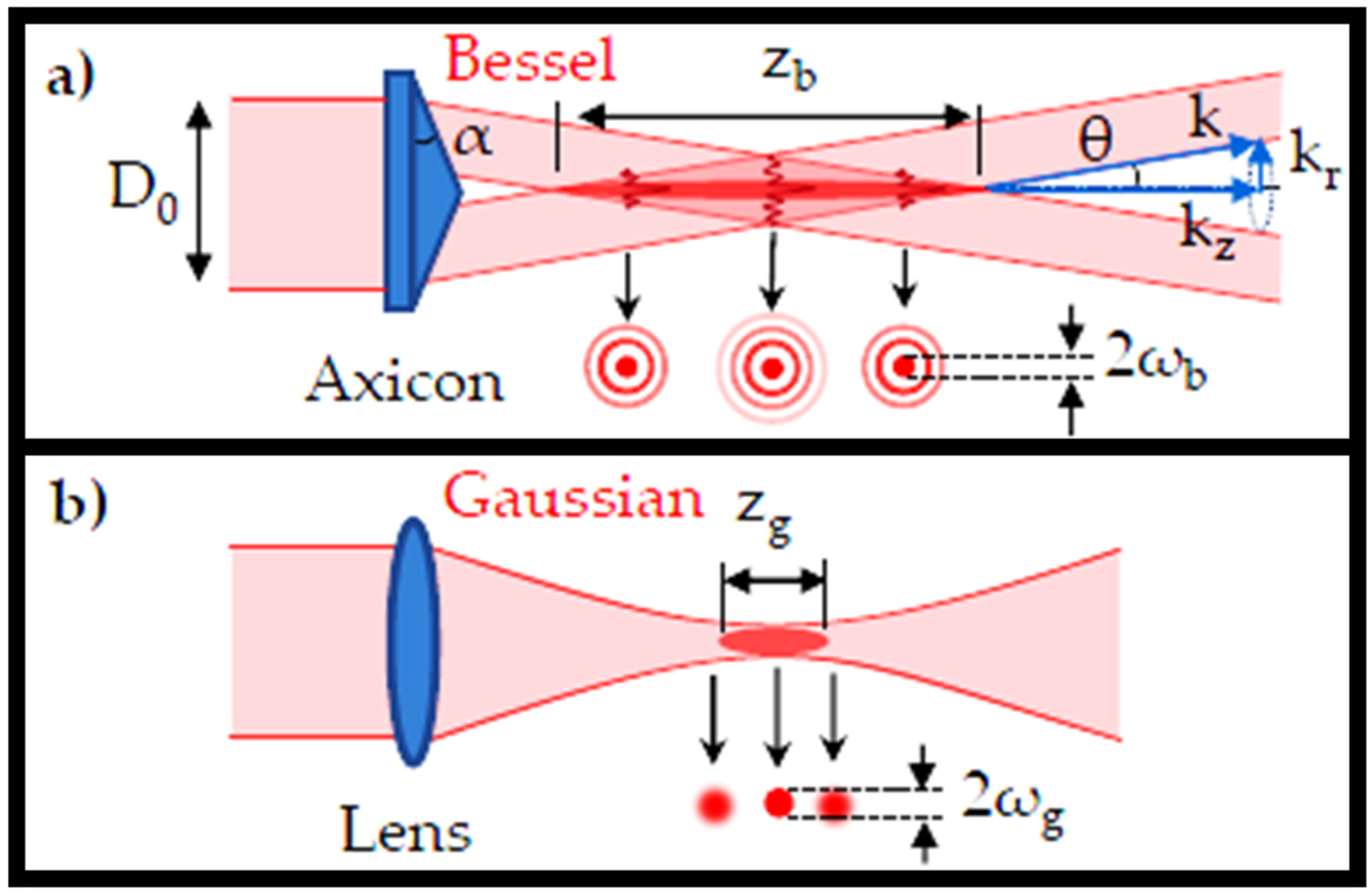
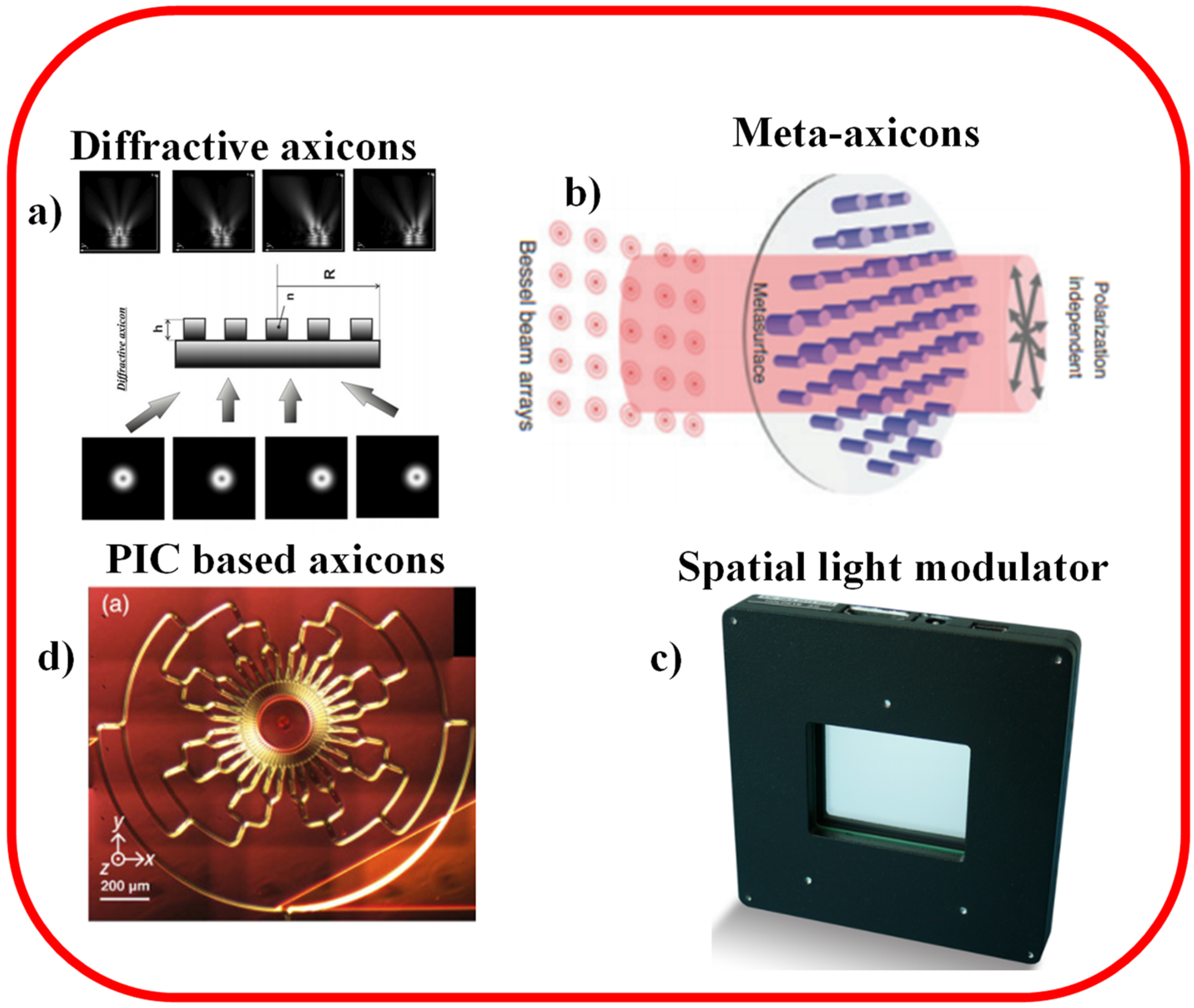
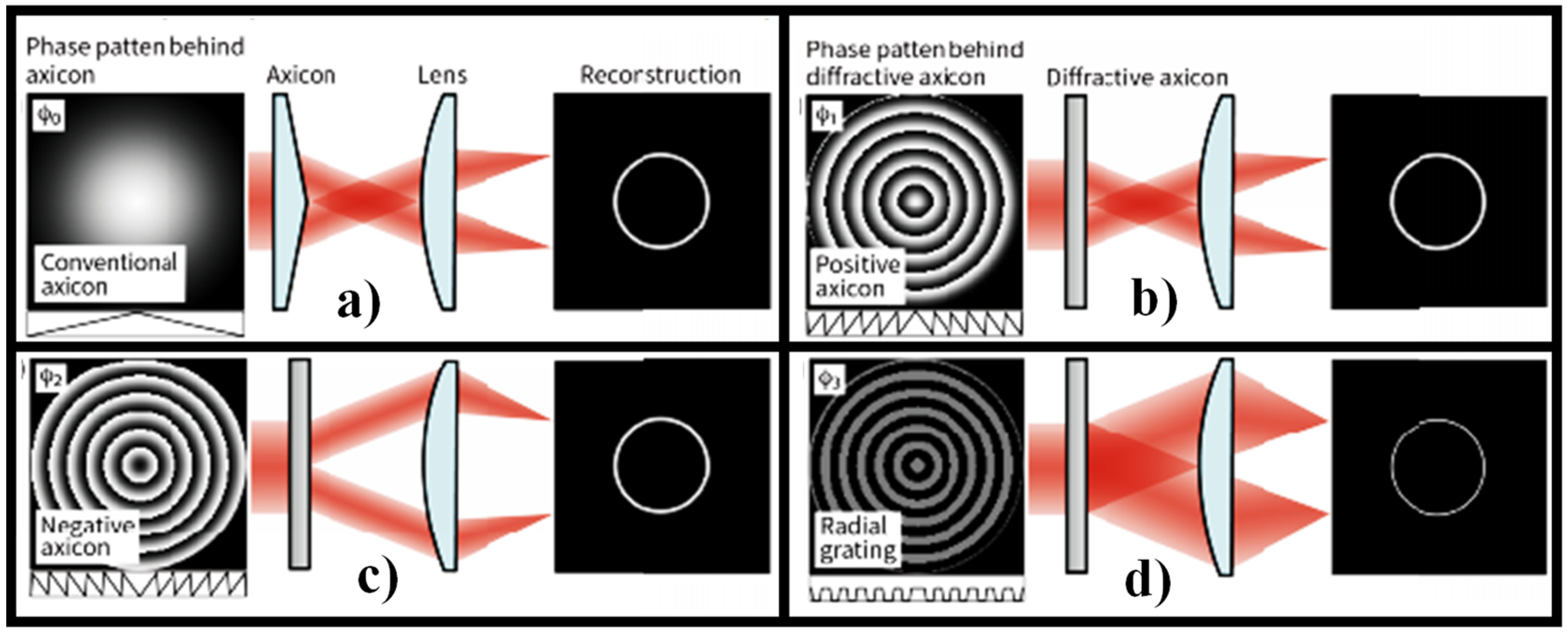
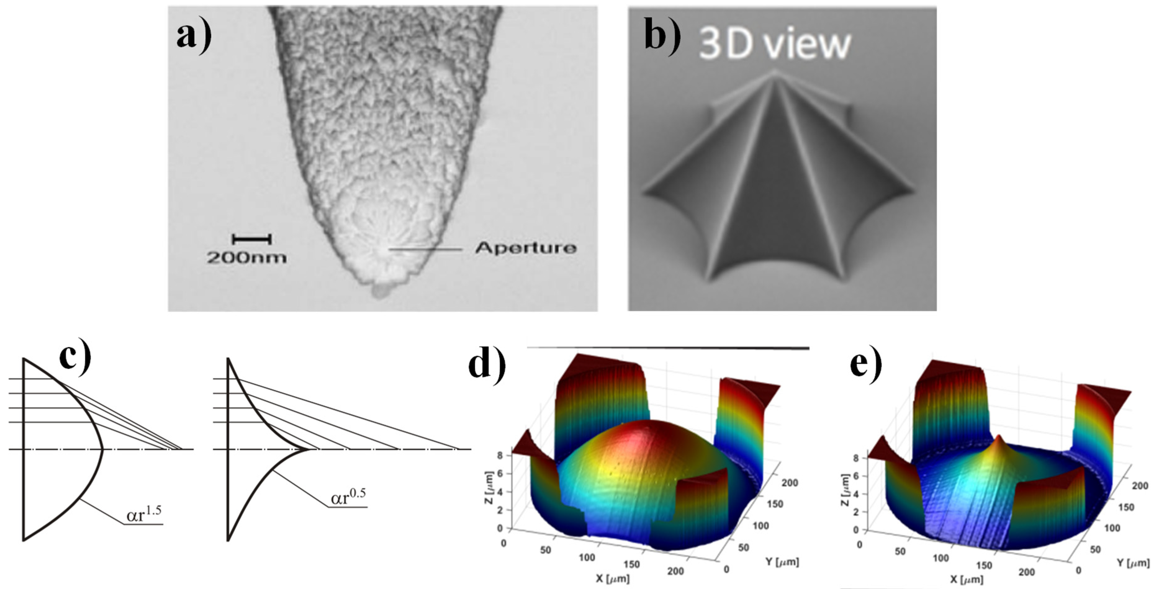
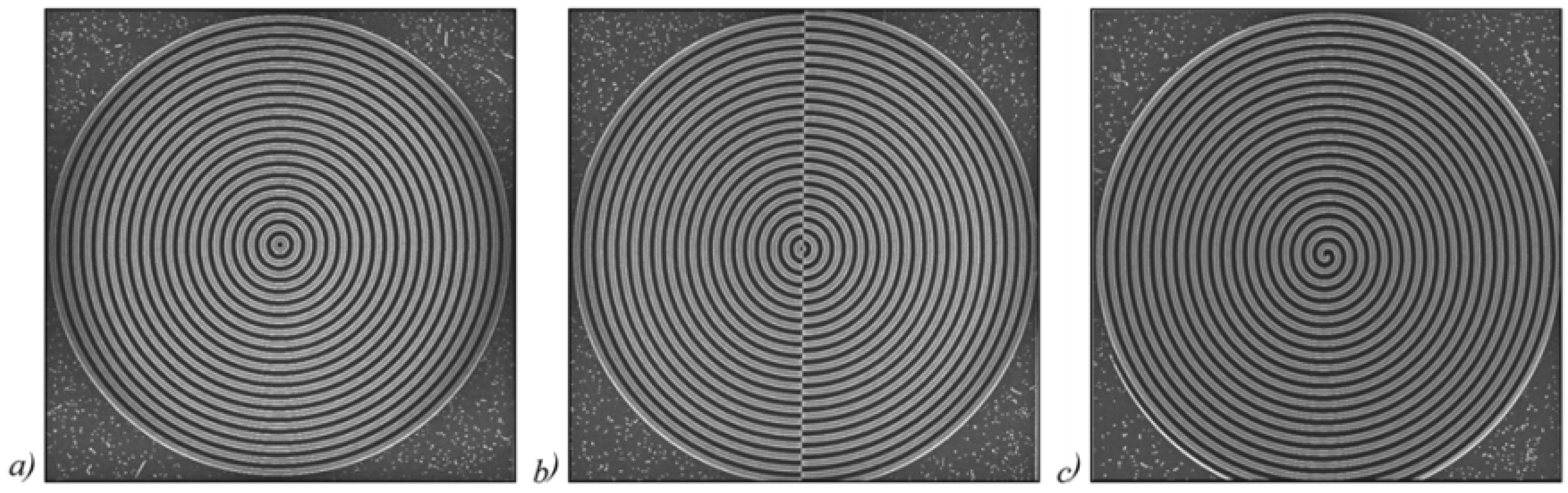
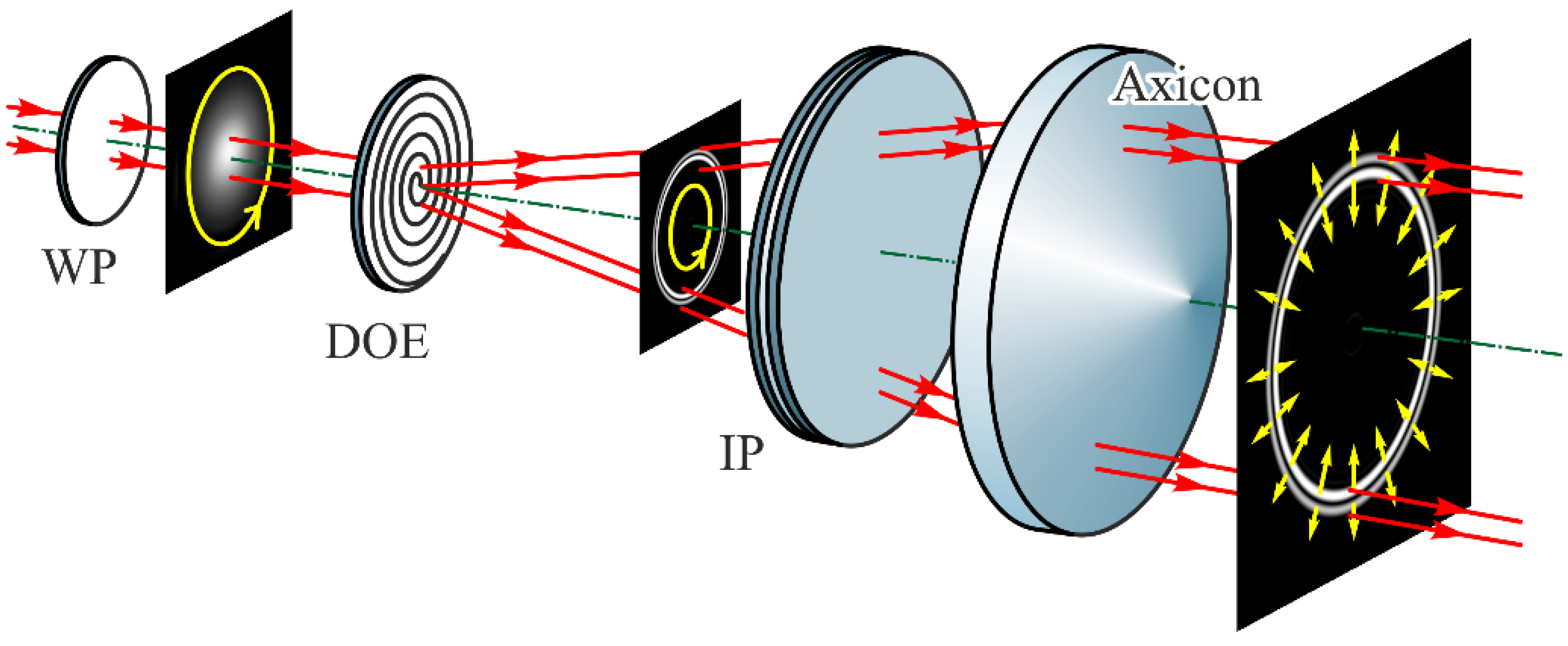
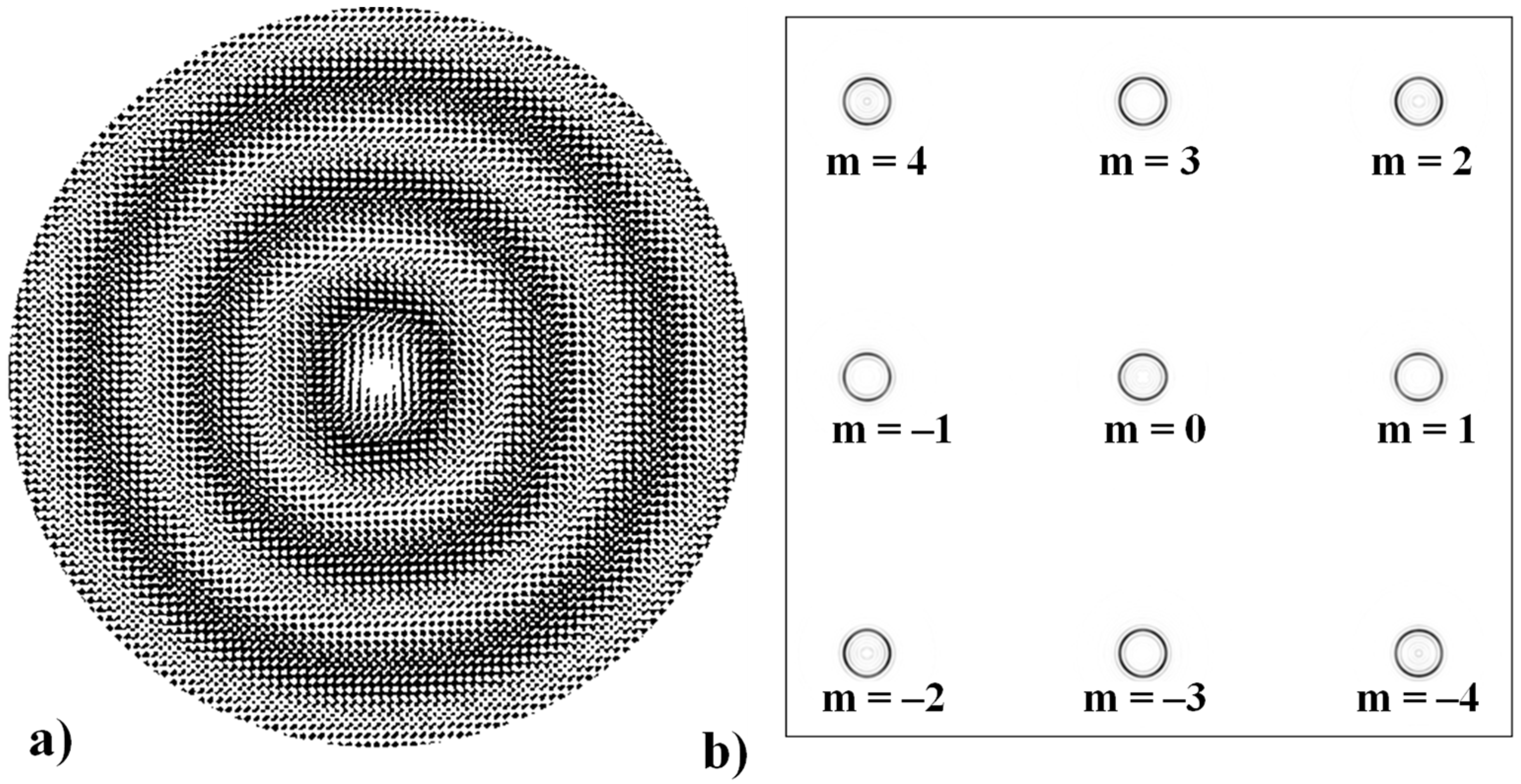
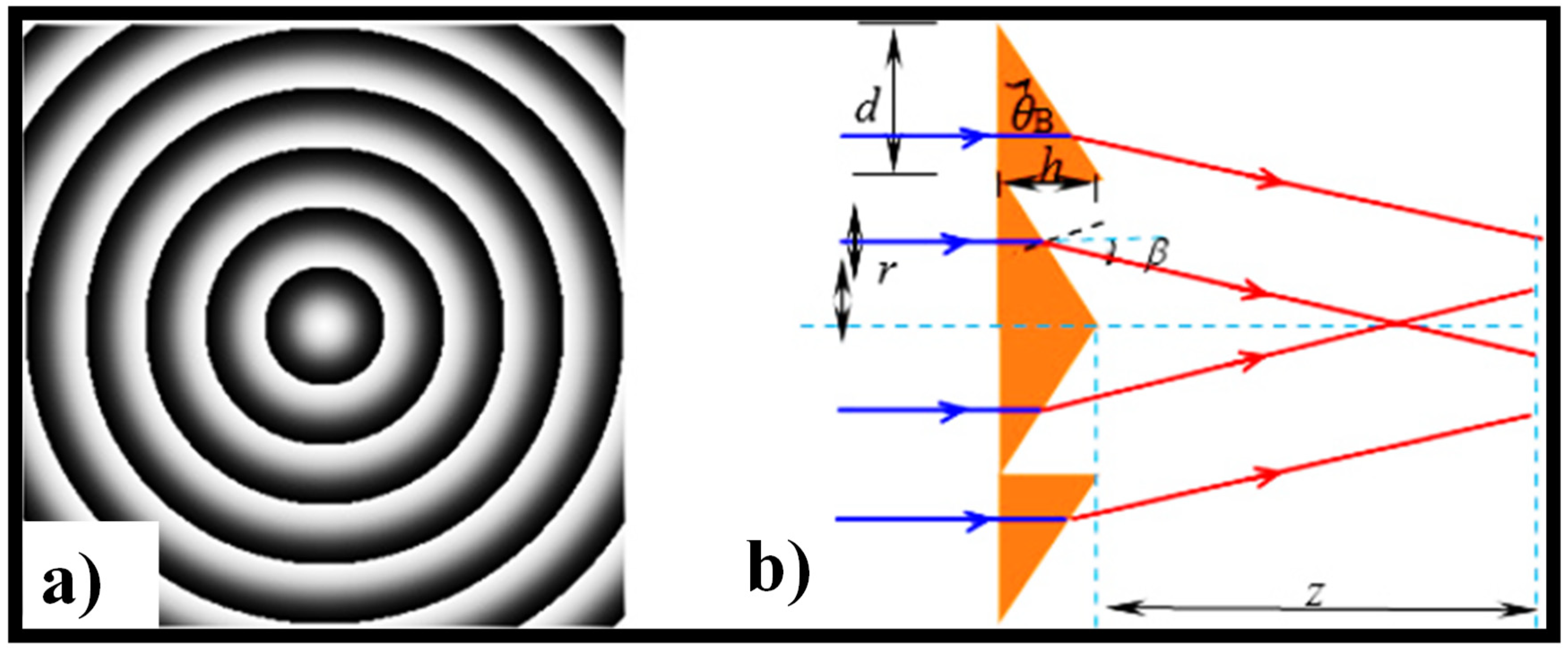
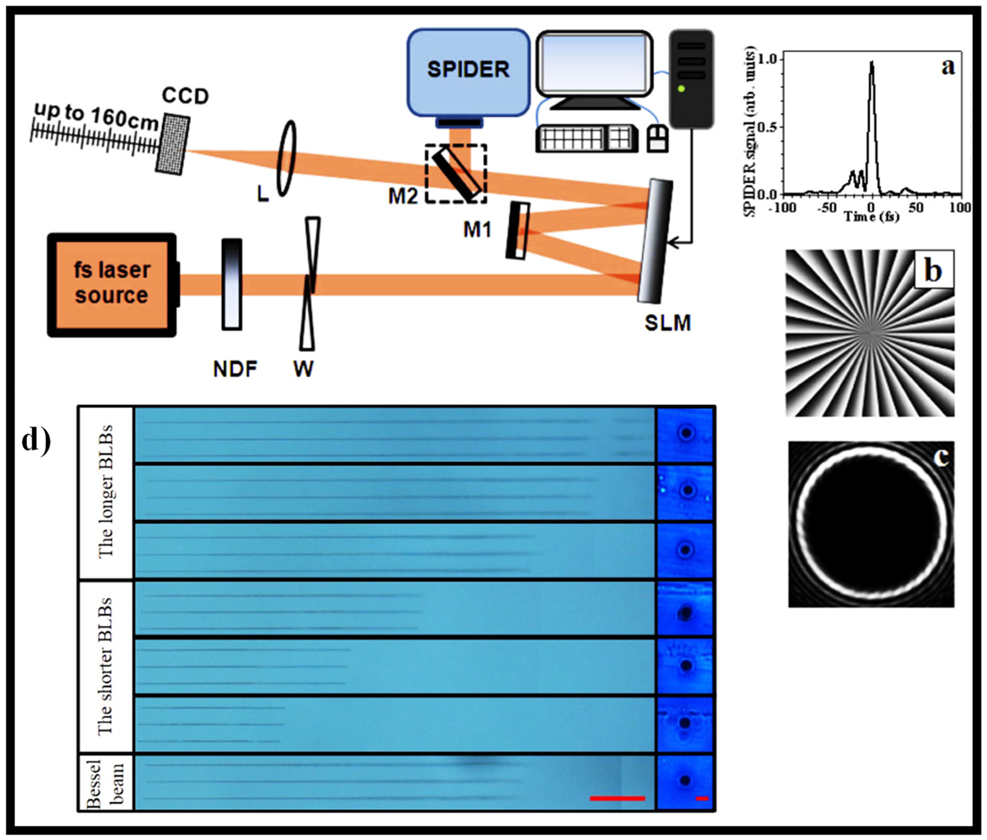
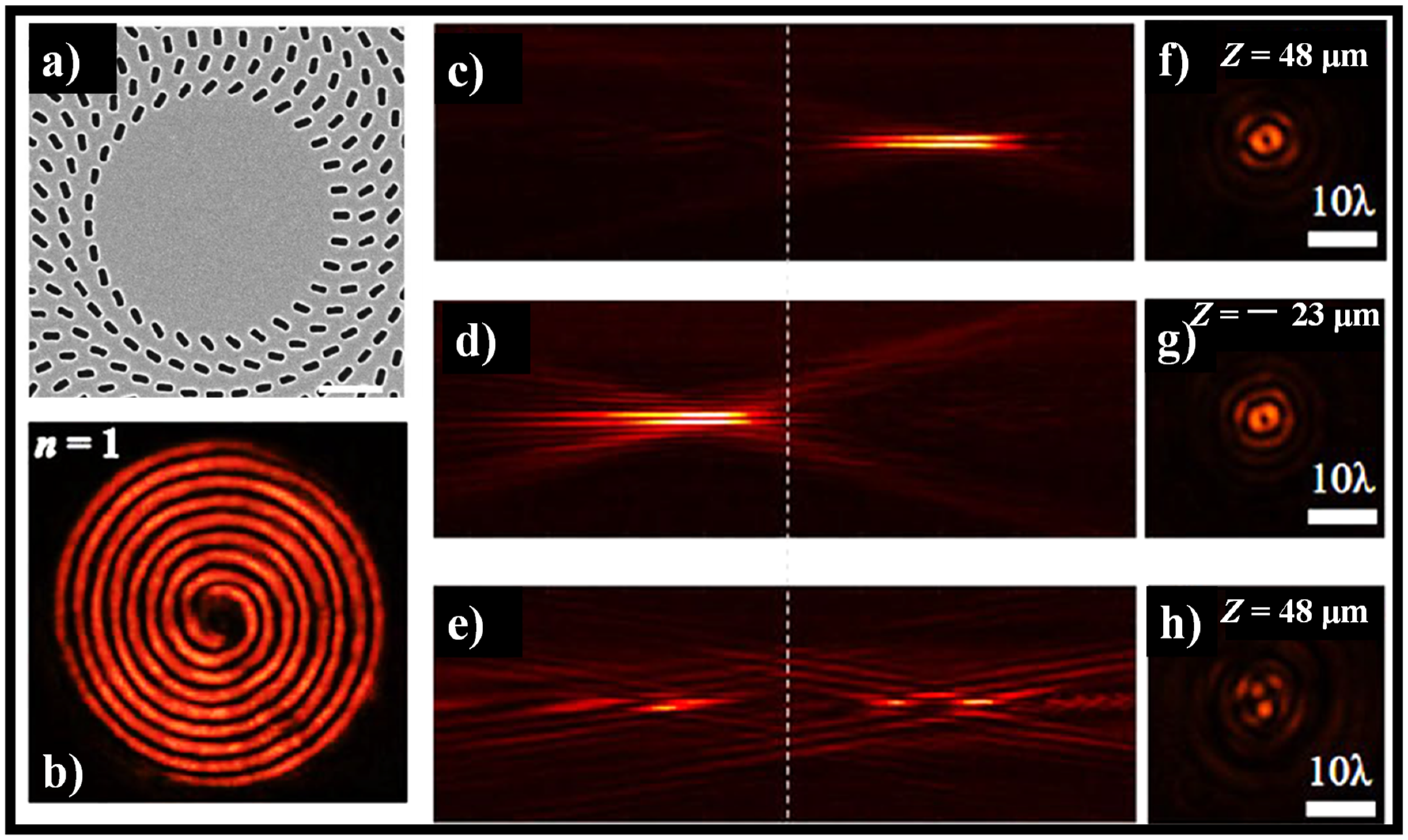
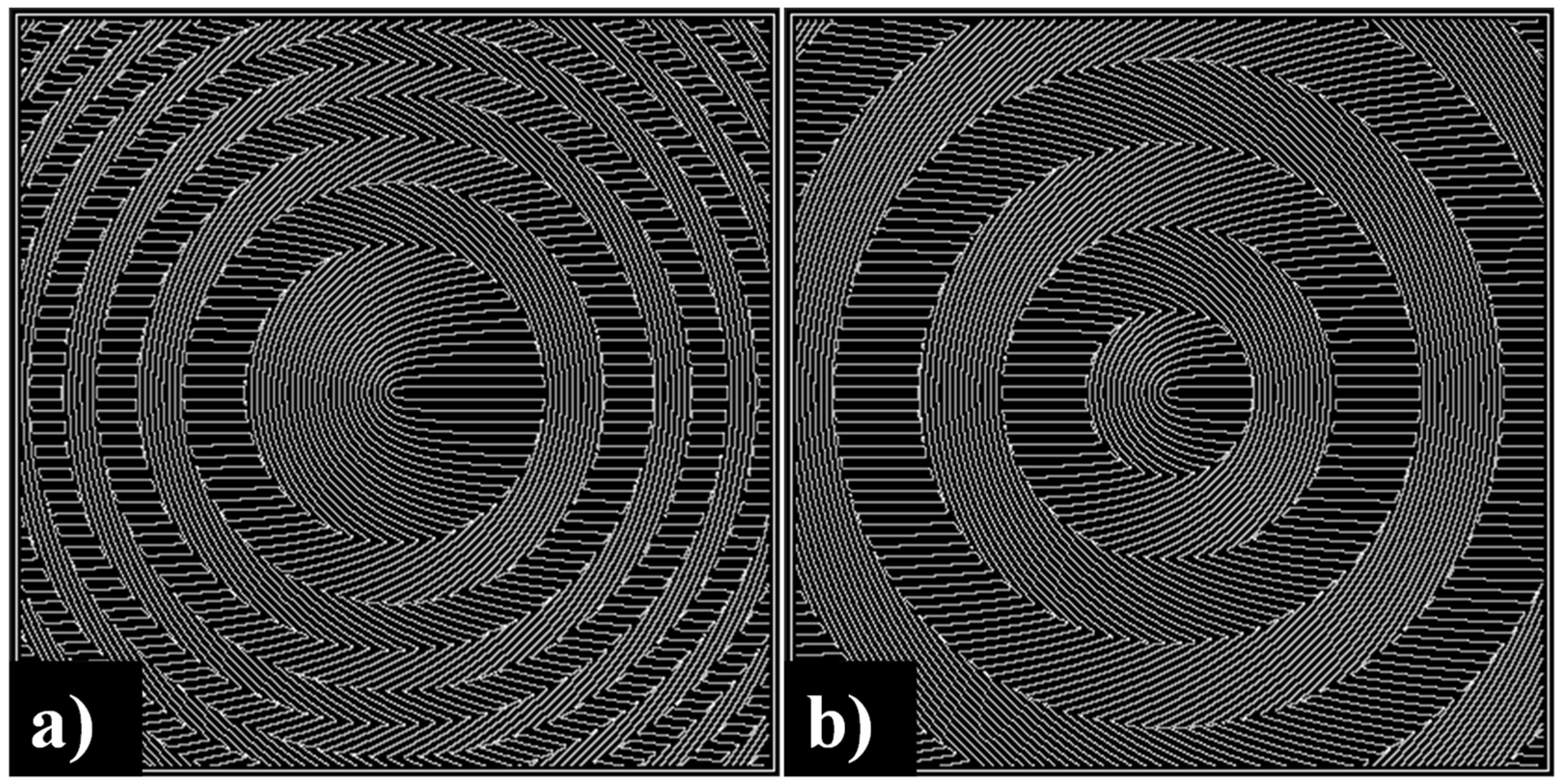
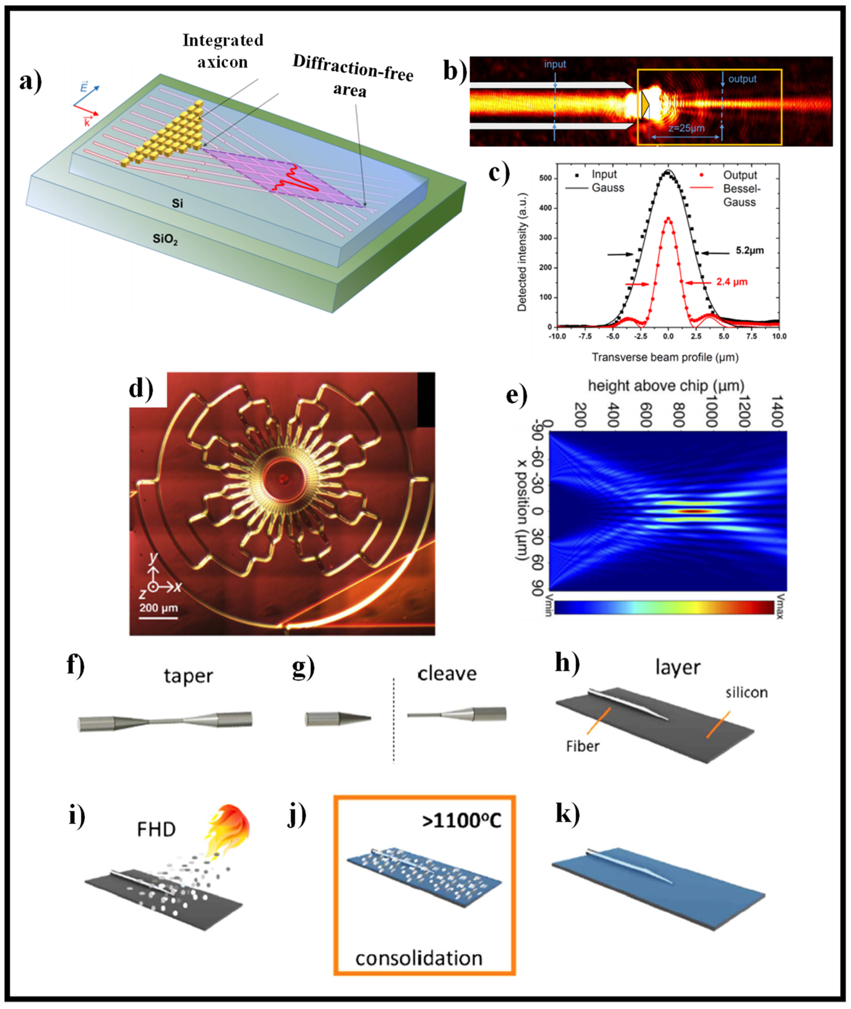
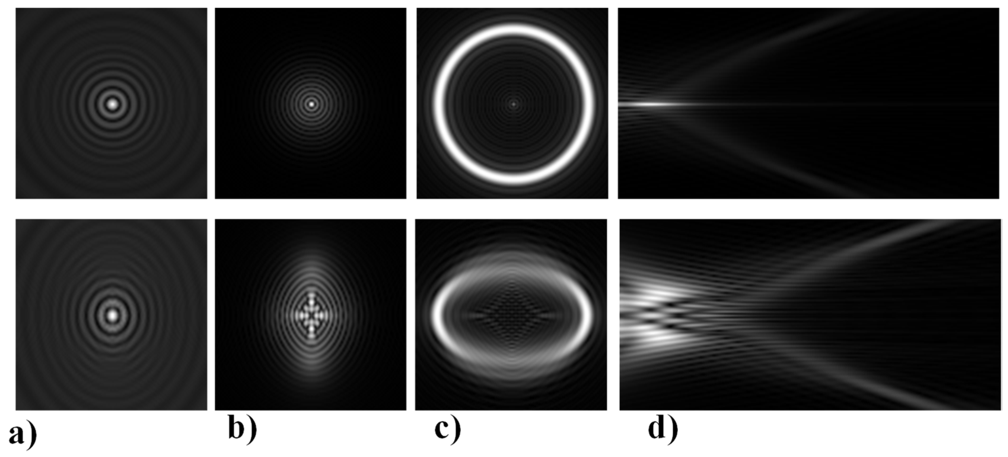
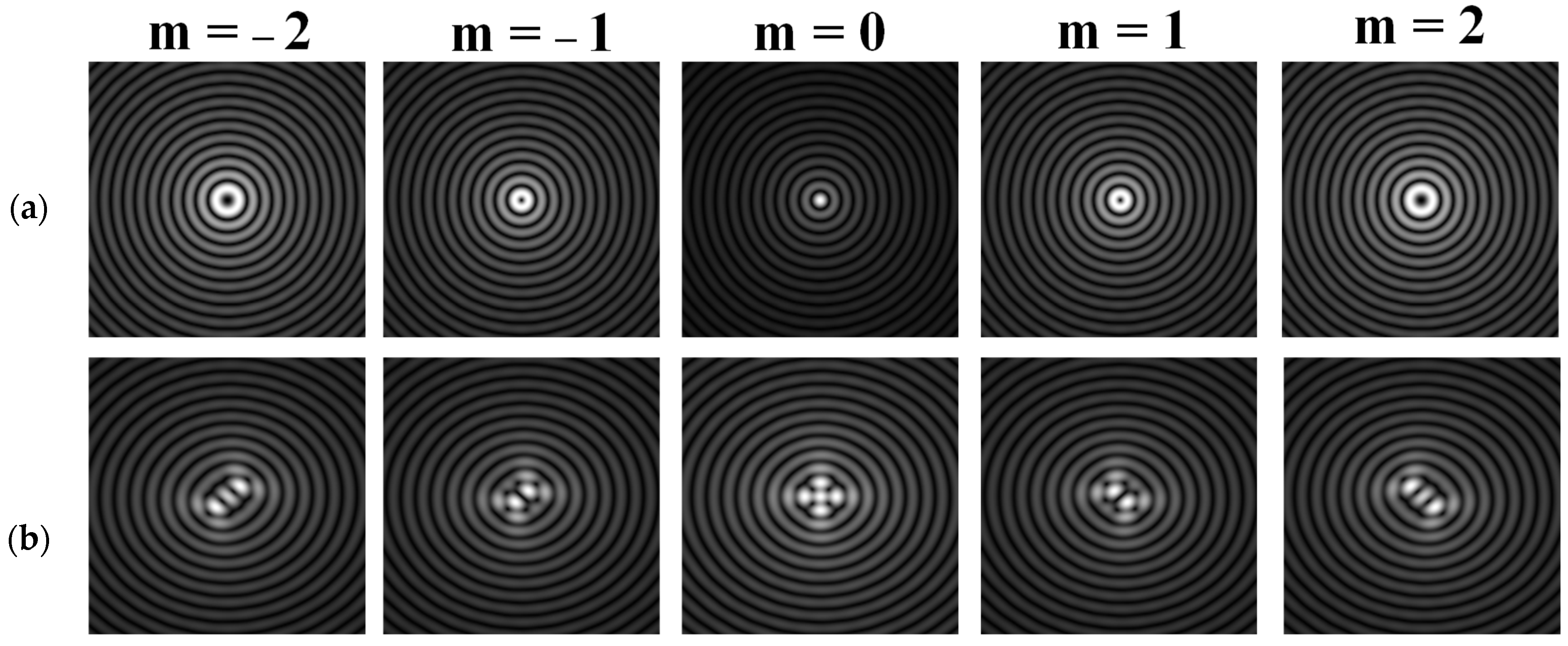
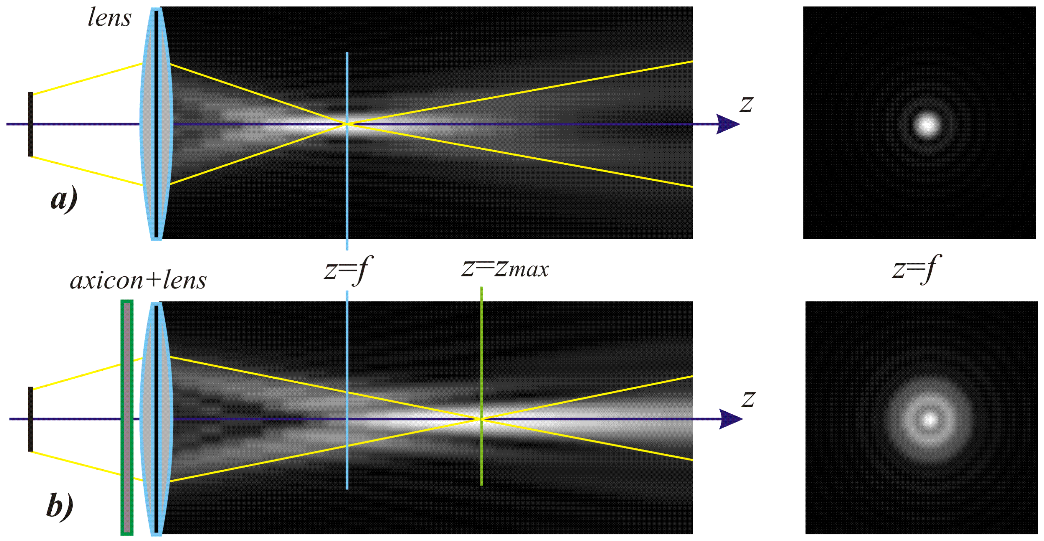
Table 1.
Simulation results for distribution near the focal plane in the presence of wavefront aberrations for a single lens (upper lines for each row) and a lens supplemented with an axicon (lower lines for each row).
Table 1.
Simulation results for distribution near the focal plane in the presence of wavefront aberrations for a single lens (upper lines for each row) and a lens supplemented with an axicon (lower lines for each row).
| Aberration Type | Longitudinal Amplitude Distribution | Transverse Distribution of Amplitude at Different Distances | ||
|---|---|---|---|---|
| z = 250 mm | z = f = 500 mm | z = 750 mm | ||
Tilt |  |  |  |  |
Defocus |  |  |  |  |
Astigmatism |  |  |  |  |
Pure coma |  |  |  |  |
Trefoil |  |  |  |  |
Quadrofoil |  |  |  |  |
Publisher’s Note: MDPI stays neutral with regard to jurisdictional claims in published maps and institutional affiliations. |
© 2021 by the authors. Licensee MDPI, Basel, Switzerland. This article is an open access article distributed under the terms and conditions of the Creative Commons Attribution (CC BY) license (https://creativecommons.org/licenses/by/4.0/).
Share and Cite
MDPI and ACS Style
Khonina, S.N.; Kazanskiy, N.L.; Khorin, P.A.; Butt, M.A. Modern Types of Axicons: New Functions and Applications. Sensors 2021, 21, 6690. https://doi.org/10.3390/s21196690
AMA Style
Khonina SN, Kazanskiy NL, Khorin PA, Butt MA. Modern Types of Axicons: New Functions and Applications. Sensors. 2021; 21(19):6690. https://doi.org/10.3390/s21196690
Chicago/Turabian StyleKhonina, Svetlana N., Nikolay L. Kazanskiy, Pavel A. Khorin, and Muhammad A. Butt. 2021. "Modern Types of Axicons: New Functions and Applications" Sensors 21, no. 19: 6690. https://doi.org/10.3390/s21196690
Note that from the first issue of 2016, this journal uses article numbers instead of page numbers. See further details here.