
Effect of Twisted Fin Array in a Triple-Tube Latent Heat Storage System during the Charging Mode

 ,
,  ,
,  , , and
Abstract
:1. Introduction
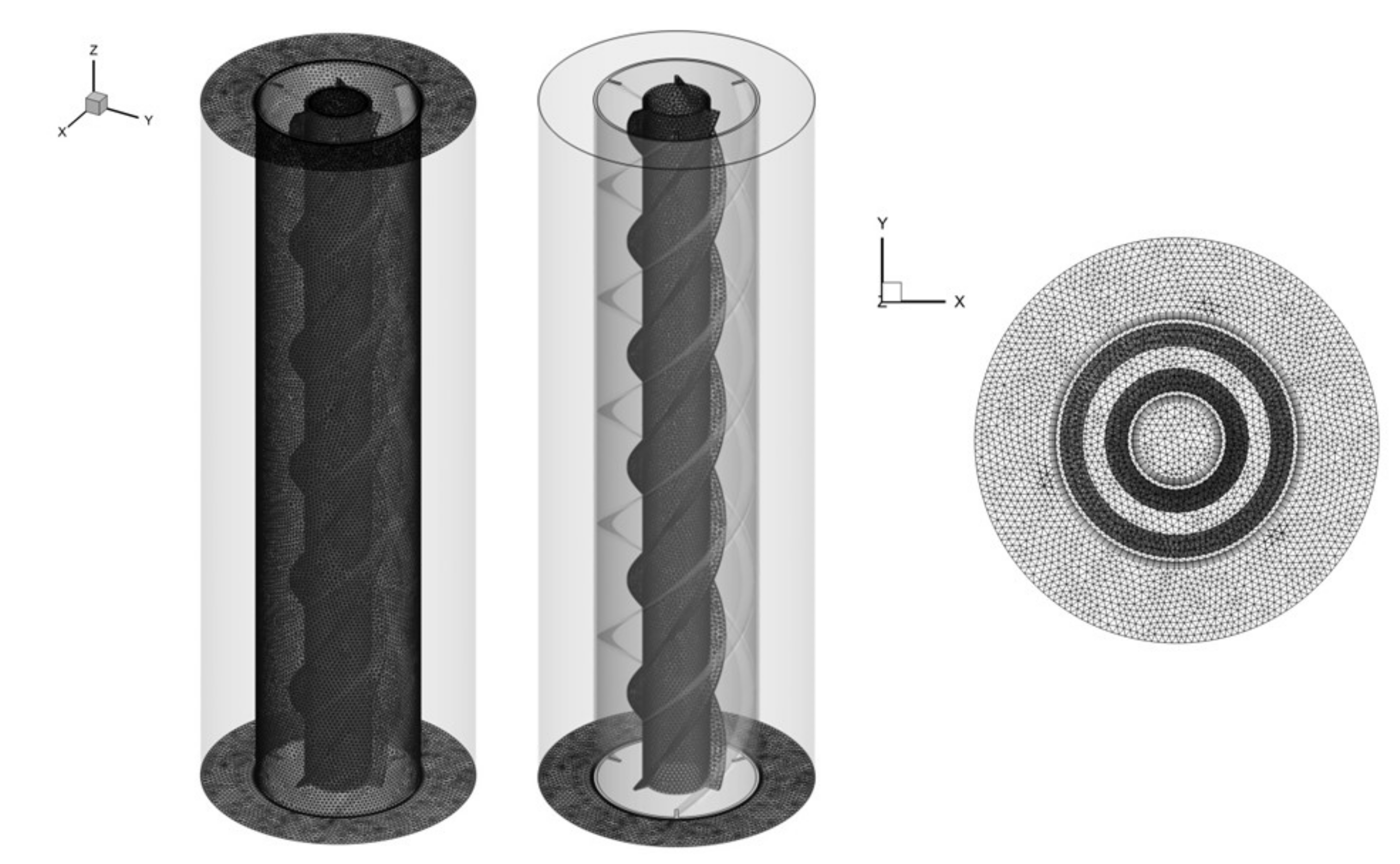
2. Geometry and Boundary Conditions
3. Mathematical Modeling
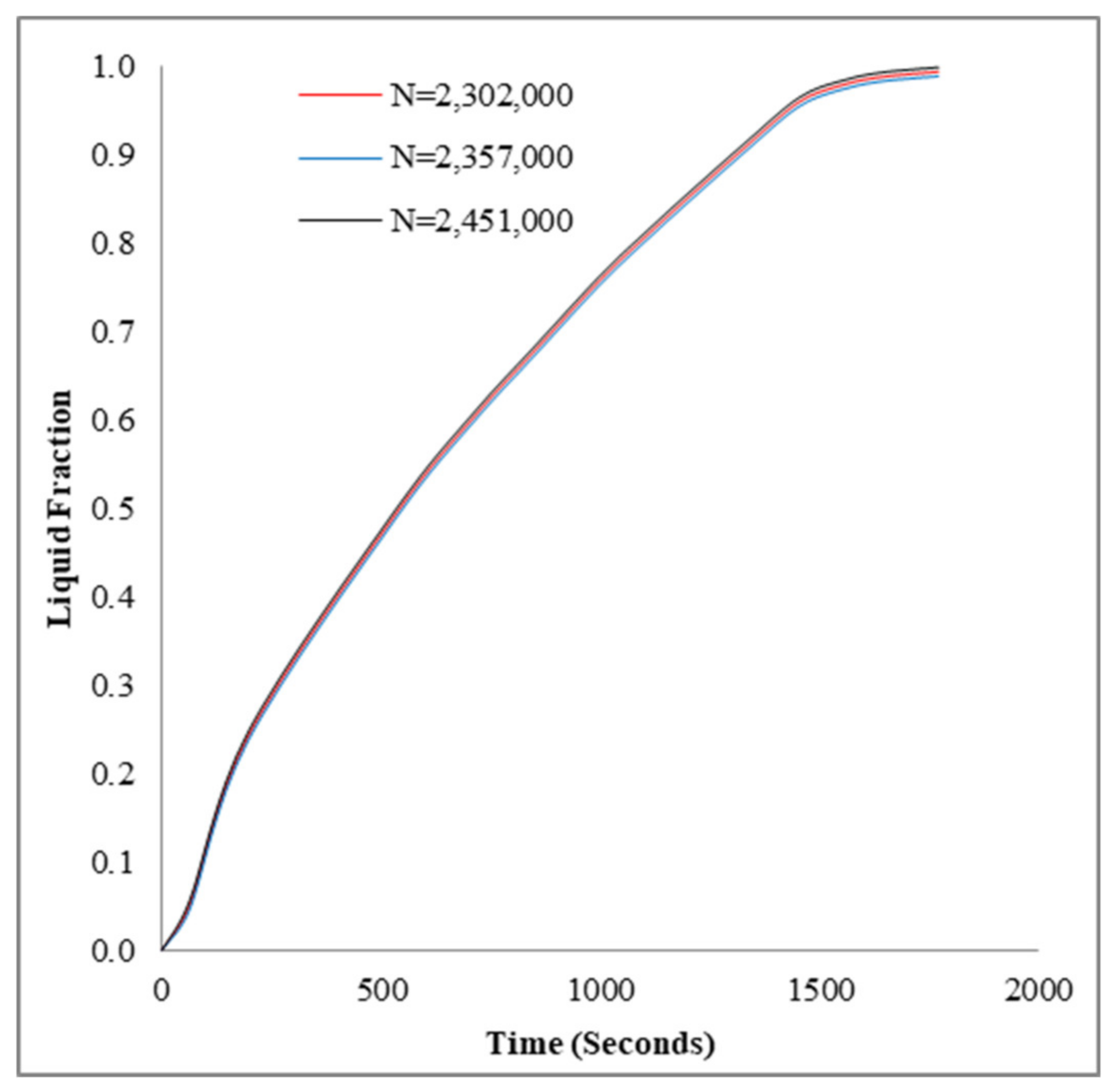
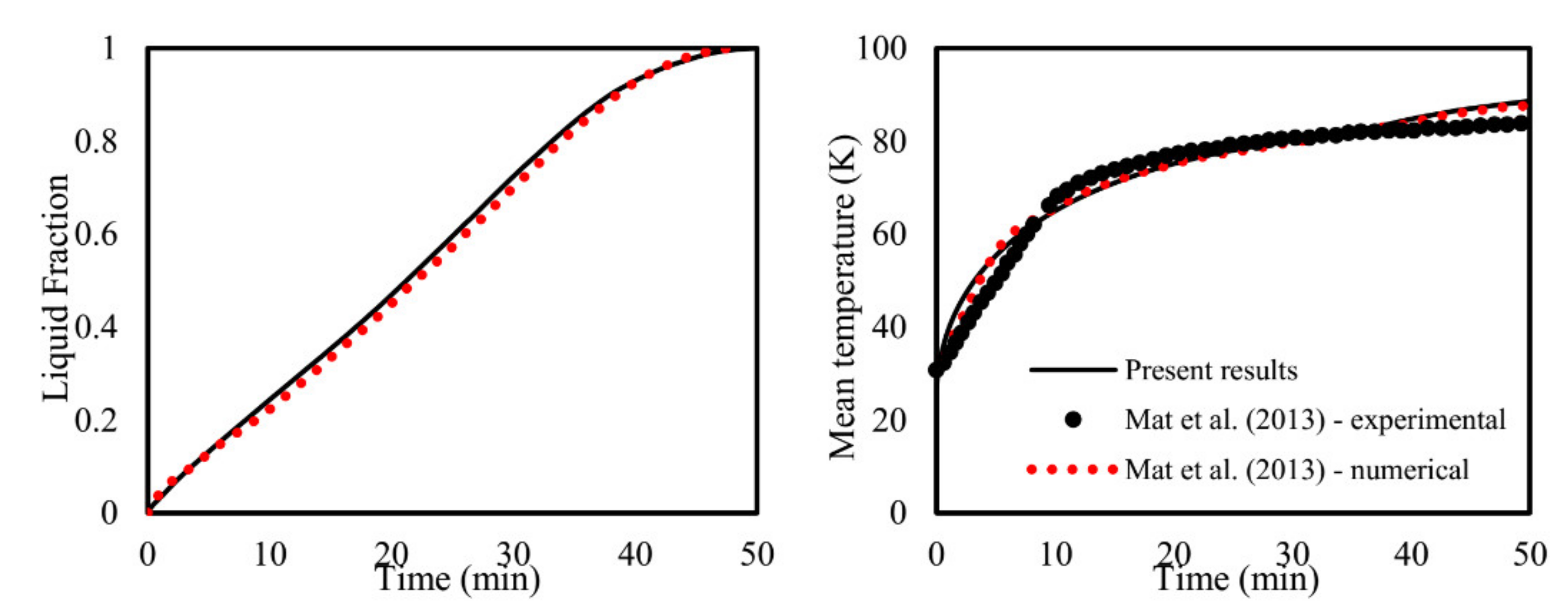
4. Numerical Process
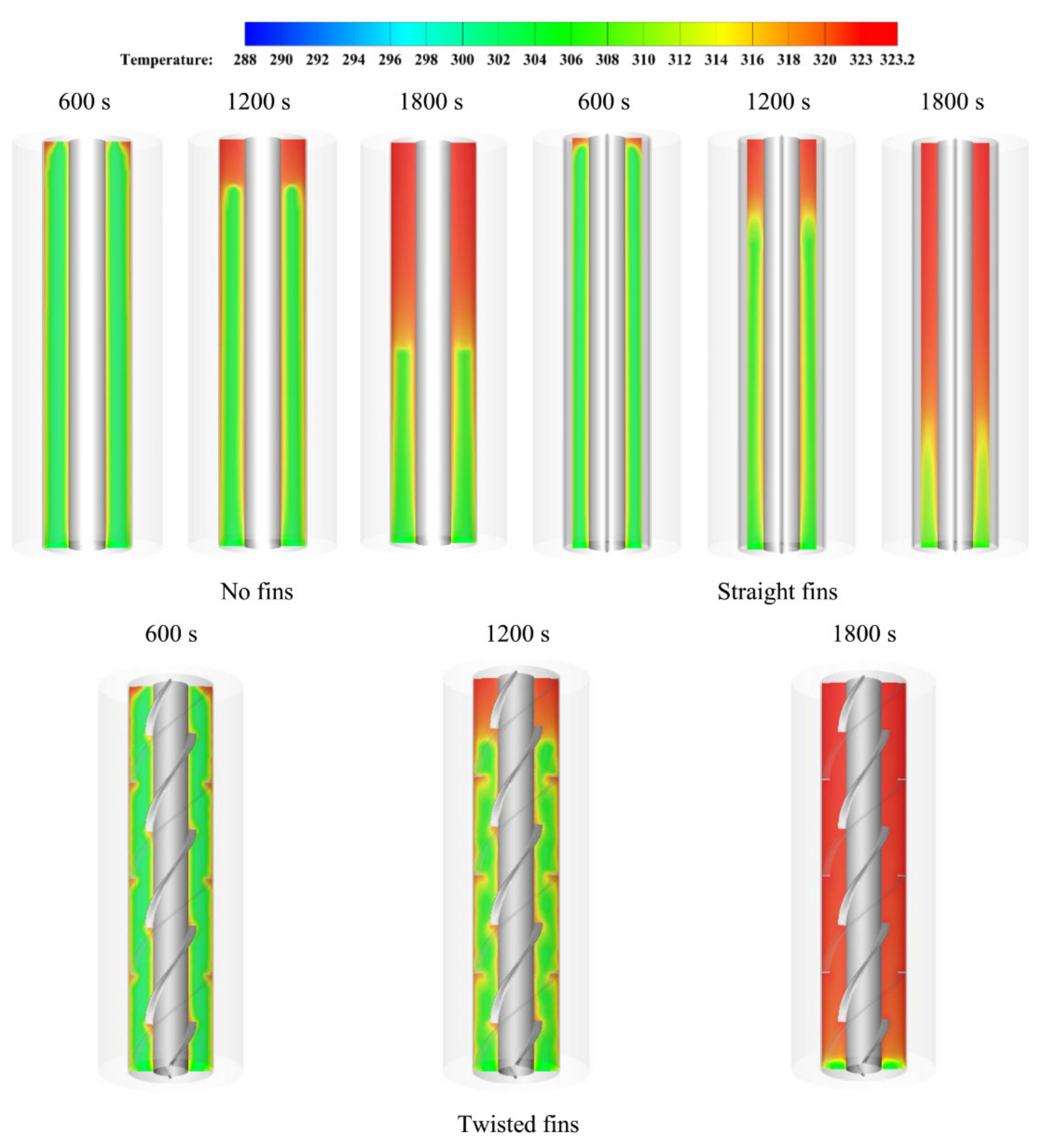
5. Results and Discussion
6. Conclusions
Author Contributions
Funding
Institutional Review Board Statement
Informed Consent Statement
Data Availability Statement
Conflicts of Interest
References
- Rahdar, M.H.; Emamzadeh, A.; Ataei, A. A comparative study on PCM and ice thermal energy storage tank for air-conditioning systems in office buildings. Appl. Therm. Eng. 2016, 96, 391–399. [Google Scholar] [CrossRef]
- Ibrahim, N.I.; Khan, M.M.A.; Mahbubul, I.; Saidur, R.; Al-Sulaiman, F.A. Experimental testing of the performance of a solar absorption cooling system assisted with ice-storage for an office space. Energy Convers. Manag. 2017, 148, 1399–1408. [Google Scholar] [CrossRef]
- Hasnain, S. Review on sustainable thermal energy storage technologies, Part I: Heat storage materials and techniques. Energy Convers. Manag. 1998, 39, 1127–1138. [Google Scholar] [CrossRef]
- Mahdi, J.M.; Lohrasbi, S.; Nsofor, E.C. Hybrid heat transfer enhancement for latent-heat thermal energy storage systems: A review. Int. J. Heat Mass Transf. 2019, 137, 630–649. [Google Scholar] [CrossRef]
- Mahmood, A.S. Experimental Study on Double-Pass Solar Air Heater with and without using Phase Change Material. J. Eng. 2019, 25, 1–17. [Google Scholar] [CrossRef] [Green Version]
- Mohammed, H.I.; Talebizadehsardari, P.; Mahdi, J.M.; Arshad, A.; Sciacovelli, A.; Giddings, D. Improved melting of latent heat storage via porous medium and uniform Joule heat generation. J. Energy Storage 2020, 31, 101747. [Google Scholar] [CrossRef]
- Fan, L.; Khodadadi, J.M. Thermal conductivity enhancement of phase change materials for thermal energy storage: A review. Renew. Sustain. Energy Rev. 2011, 15, 24–46. [Google Scholar] [CrossRef]
- Mahdi, J.M.; Nsofor, E.C. Solidification of a PCM with nanoparticles in triplex-tube thermal energy storage system. Appl. Therm. Eng. 2016, 108, 596–604. [Google Scholar] [CrossRef]
- Mahdi, J.M.; Lohrasbi, S.; Ganji, D.D.; Nsofor, E.C. Simultaneous energy storage and recovery in the triplex-tube heat exchanger with PCM, copper fins and Al2O3 nanoparticles. Energy Convers. Manag. 2019, 180, 949–961. [Google Scholar] [CrossRef]
- Mahdi, J.M.; Mohammed, H.I.; Hashim, E.T.; Talebizadehsardari, P.; Nsofor, E.C. Solidification enhancement with multiple PCMs, cascaded metal foam and nanoparticles in the shell-and-tube energy storage system. Appl. Energy 2020, 257, 113993. [Google Scholar] [CrossRef]
- Sivasamy, P.; Devaraju, A.; Harikrishnan, S. Review on heat transfer enhancement of phase change materials (PCMs). Mater. Today Proc. 2018, 5, 14423–14431. [Google Scholar] [CrossRef]
- Yang, L.; Huang, J.-N.; Zhou, F. Thermophysical properties and applications of nano-enhanced PCMs: An update review. Energy Convers. Manag. 2020, 214, 112876. [Google Scholar] [CrossRef]
- Kamkari, B.; Shokouhmand, H. Experimental investigation of phase change material melting in rectangular enclosures with horizontal partial fins. Int. J. Heat Mass Transf. 2014, 78, 839–851. [Google Scholar] [CrossRef]
- Yıldız, Ç.; Arıcı, M.; Nižetić, S.; Shahsavar, A. Numerical investigation of natural convection behavior of molten PCM in an enclosure having rectangular and tree-like branching fins. Energy 2020, 207, 118223. [Google Scholar] [CrossRef]
- Tang, S.-Z.; Tian, H.-Q.; Zhou, J.-J.; Li, H. Evaluation and optimization of melting performance in a horizontal thermal energy storage unit with non-uniform fins. J. Energy Storage 2021, 33, 102124. [Google Scholar] [CrossRef]
- Dai, R.; Mostaghimi, J.; Li, N.; Deng, T.; Wang, Q.; Zeng, M. Charging time and energy storage rate analysis of fin effect inside the horizontal tube for thermal energy storage. J. Clean. Prod. 2020, 273, 123030. [Google Scholar] [CrossRef]
- Yang, X.; Guo, J.; Yang, B.; Cheng, H.; Wei, P.; He, Y.-L. Design of non-uniformly distributed annular fins for a shell-and-tube thermal energy storage unit. Appl. Energy 2020, 279, 115772. [Google Scholar] [CrossRef]
- Nakhchi, M.; Esfahani, J. Improving the melting performance of PCM thermal energy storage with novel stepped fins. J. Energy Storage 2020, 30, 101424. [Google Scholar] [CrossRef]
- Mahood, H.B.; Mahdi, M.S.; Monjezi, A.A.; Khadom, A.A.; Campbell, A.N. Numerical investigation on the effect of fin design on the melting of phase change material in a horizontal shell and tube thermal energy storage. J. Energy Storage 2020, 29, 101331. [Google Scholar] [CrossRef]
- Dammak, K.; El Hami, A. Thermal reliability-based design optimization using Kriging model of PCM based pin fin heat sink. Int. J. Heat Mass Transf. 2021, 166, 120745. [Google Scholar] [CrossRef]
- Xu, H.; Wang, N.; Zhang, C.; Qu, Z.; Cao, M. Optimization on the melting performance of triplex-layer PCMs in a horizontal finned shell and tube thermal energy storage unit. Appl. Therm. Eng. 2020, 176, 115409. [Google Scholar] [CrossRef]
- Augspurger, M.; Choi, K.; Udaykumar, H. Optimizing fin design for a PCM-based thermal storage device using dynamic Kriging. Int. J. Heat Mass Transf. 2018, 121, 290–308. [Google Scholar] [CrossRef]
- Zhang, C.; Sun, Q.; Chen, Y. Solidification behaviors and parametric optimization of finned shell-tube ice storage units. Int. J. Heat Mass Transf. 2020, 146, 118836. [Google Scholar] [CrossRef]
- Kolioak, Y.; Radhakrishna, M.; Prasad, A. Optimization of Heat Energy Based on Phase Change Materials used in Solar Collector using Taguchi Method. Mater. Today Proc. 2020, 22, 2404–2411. [Google Scholar] [CrossRef]
- Ren, H.; Lin, W.; Ma, Z.; Fan, W.; Wang, X. Thermal performance evaluation of an integrated photovoltaic thermal-phase change material system using Taguchi method. Energy Procedia 2017, 121, 118–125. [Google Scholar] [CrossRef]
- Xie, J.; Yuan, C. Parametric study of ice thermal storage system with thin layer ring by Taguchi method. Appl. Therm. Eng. 2016, 98, 246–255. [Google Scholar] [CrossRef] [Green Version]
- Lin, W.; Ma, Z. Using Taguchi-Fibonacci search method to optimize phase change materials enhanced buildings with integrated solar photovoltaic thermal collectors. Energy 2016, 106, 23–37. [Google Scholar] [CrossRef]
- Lin, W.; Ma, Z.; Ren, H.; Gschwander, S.; Wang, S. Multi-objective optimisation of thermal energy storage using phase change materials for solar air systems. Renew. Energy 2019, 130, 1116–1129. [Google Scholar] [CrossRef]
- Sun, X.; Mo, Y.; Li, J.; Chu, Y.; Liu, L.; Liao, S. Study on the energy charging process of a plate-type latent heat thermal energy storage unit and optimization using Taguchi method. Appl. Therm. Eng. 2020, 164, 114528. [Google Scholar] [CrossRef]
- Li, Z.; Shahsavar, A.; Al-Rashed, A.A.A.A.; Talebizadehsardari, P. Effect of porous medium and nanoparticles presences in a counter-current triple-tube composite porous/nano-PCM system. Appl. Therm. Eng. 2020, 167, 114777. [Google Scholar] [CrossRef]
- GmbH, R.T. RT35 Data Sheet. Available online: https://www.rubitherm.eu/en/index.php/productcategory/organische-pcm-rt (accessed on 10 November 2020).
- Talebizadeh Sardari, P.; Walker, G.S.; Gillott, M.; Grant, D.; Giddings, D. Numerical modelling of phase change material melting process embedded in porous media: Effect of heat storage size. Proc. Inst. Mech. Eng. Part A J. Power Energy 2019. [Google Scholar] [CrossRef]
- Shahsavar, A.; Majidzadeh, A.H.; Mahani, R.B.; Talebizadehsardari, P. Entropy and Thermal performance Analysis of PCM Melting and Solidification Mechanisms in a Wavy Channel Triplex-Tube Heat Exchanger. Renew. Energy 2021, 165, 52–72. [Google Scholar] [CrossRef]
- Mahdi, J.M.; Lohrasbi, S.; Ganji, D.D.; Nsofor, E.C. Accelerated melting of PCM in energy storage systems via novel configuration of fins in the triplex-tube heat exchanger. Int. J. Heat Mass Transf. 2018, 124, 663–676. [Google Scholar] [CrossRef]
- Talebizadehsardari, P.; Mohammed, H.I.; Mahdi, J.M.; Gillott, M.; Walker, G.S.; Grant, D.; Giddings, D. Effect of airflow channel arrangement on the discharge of a composite metal foam-phase change material heat exchanger. Int. J. Energy Res. 2020. [Google Scholar] [CrossRef]
- Al-Abidi, A.A.; Mat, S.; Sopian, K.; Sulaiman, M.Y.; Mohammad, A.T. Internal and external fin heat transfer enhancement technique for latent heat thermal energy storage in triplex tube heat exchangers. Appl. Therm. Eng. 2013, 53, 147–156. [Google Scholar] [CrossRef]
- Xu, Y.; Ren, Q.; Zheng, Z.-J.; He, Y.-L. Evaluation and optimization of melting performance for a latent heat thermal energy storage unit partially filled with porous media. Appl. Energy 2017, 193, 84–95. [Google Scholar] [CrossRef]
- Mat, S.; Al-Abidi, A.A.; Sopian, K.; Sulaiman, M.Y.; Mohammad, A.T. Enhance heat transfer for PCM melting in triplex tube with internal–external fins. Energy Convers. Manag. 2013, 74, 223–236. [Google Scholar] [CrossRef]
- Mahdi, J.M.; Nsofor, E.C. Melting enhancement in triplex-tube latent thermal energy storage system using nanoparticles-fins combination. Int. J. Heat Mass Transf. 2017, 109, 417–427. [Google Scholar] [CrossRef]
- Mahdi, J.M.; Nsofor, E.C. Solidification enhancement of PCM in a triplex-tube thermal energy storage system with nanoparticles and fins. Appl. Energy 2018, 211, 975–986. [Google Scholar] [CrossRef]


| Property | RT35 |
|---|---|
| Specific heat (kJ/kgK) | 2 |
| Viscosity (Pas) | 0.023 |
| Heat of fusion (kJ/kg) | 170 |
| Liquidus temperature (°C) | 35 |
| Density (kg/m3) | 815 |
| Thermal conductivity (W/mK) | 0.2 |
| Solidus temperature (°C) | 29 |
| Thermal expansion coefficient (1/K) | 0.0006 |
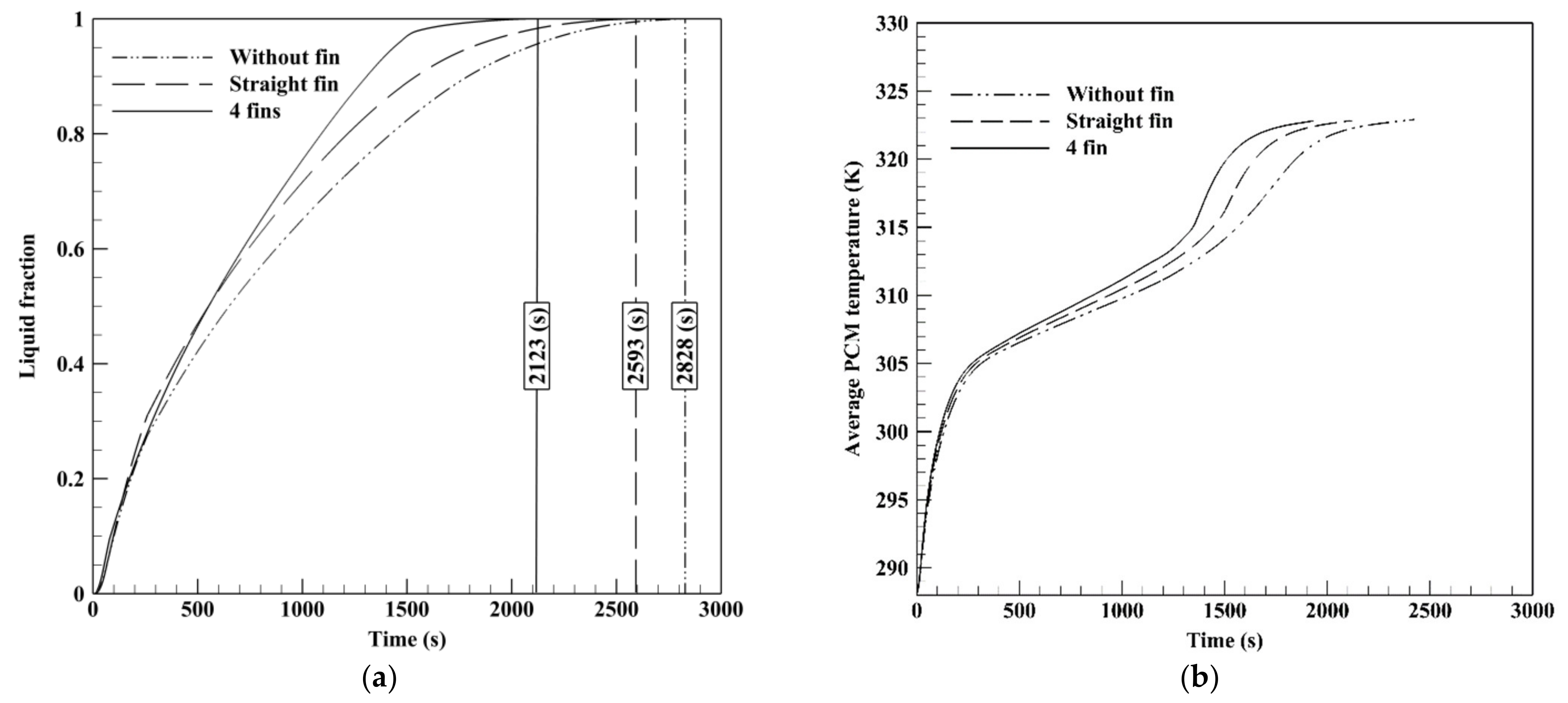
| Fins | PCM Mass (kg) | Heat Storage Capacity (J) | Melting Time (s) | Heat Storage Rate (W) |
|---|---|---|---|---|
| No fins | 0.3354 | 76,903.13 | 2828 | 27.19 |
| Straight fins | 0.3354 | 76,953.70 | 2593 | 29.67 |
| Four twisted fins | 0.3354 | 76,938.91 | 2123 | 36.24 |
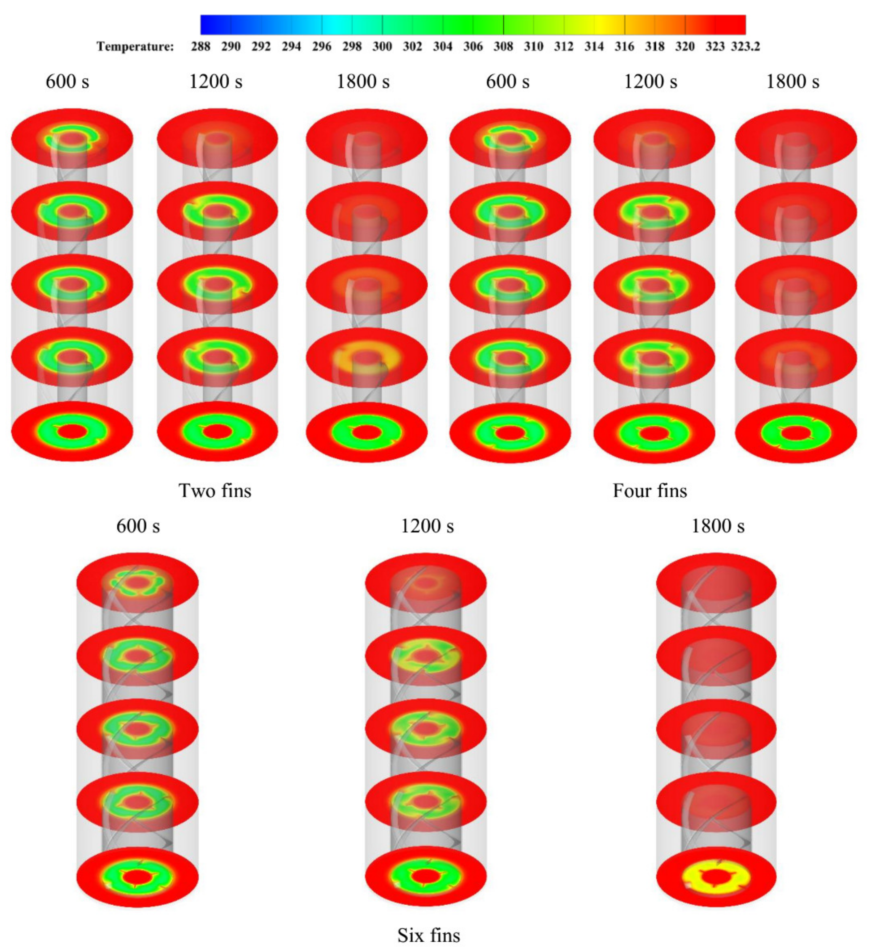
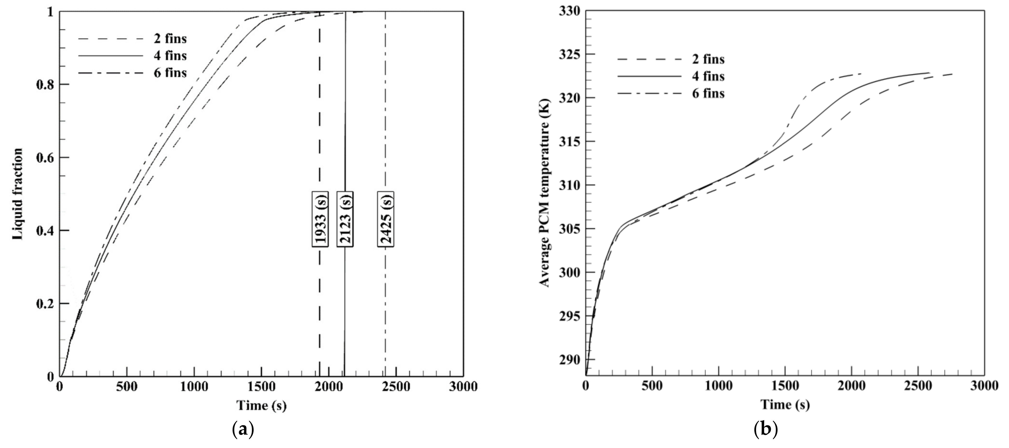
| Fins’ Number | PCM Mass (kg) | Thermal Storage Capacity (J) | Melting Time (s) | Heat Storage Rate (W) |
|---|---|---|---|---|
| Two | 0.3354 | 76,978.87 | 2425 | 31.74 |
| Four | 0.3354 | 76,938.91 | 2123 | 36.24 |
| Six | 0.3354 | 76,918.15 | 1933 | 39.79 |
Publisher’s Note: MDPI stays neutral with regard to jurisdictional claims in published maps and institutional affiliations. |
© 2021 by the authors. Licensee MDPI, Basel, Switzerland. This article is an open access article distributed under the terms and conditions of the Creative Commons Attribution (CC BY) license (http://creativecommons.org/licenses/by/4.0/).
Share and Cite
Ghalambaz, M.; Mahdi, J.M.; Shafaghat, A.; Eisapour, A.H.; Younis, O.; Talebizadeh Sardari, P.; Yaïci, W. Effect of Twisted Fin Array in a Triple-Tube Latent Heat Storage System during the Charging Mode. Sustainability 2021, 13, 2685. https://doi.org/10.3390/su13052685
Ghalambaz M, Mahdi JM, Shafaghat A, Eisapour AH, Younis O, Talebizadeh Sardari P, Yaïci W. Effect of Twisted Fin Array in a Triple-Tube Latent Heat Storage System during the Charging Mode. Sustainability. 2021; 13(5):2685. https://doi.org/10.3390/su13052685
Chicago/Turabian StyleGhalambaz, Mohammad, Jasim M. Mahdi, Amirhossein Shafaghat, Amir Hossein Eisapour, Obai Younis, Pouyan Talebizadeh Sardari, and Wahiba Yaïci. 2021. "Effect of Twisted Fin Array in a Triple-Tube Latent Heat Storage System during the Charging Mode" Sustainability 13, no. 5: 2685. https://doi.org/10.3390/su13052685