Free Vibration Analysis of Functionally Graded Shells Using an Edge-Based Smoothed Finite Element Method


1
Faculty of Mechanical Engineering, Le Quy Don Technical University, Ha Noi 100000, Vietnam
2
Center of Excellence for Automation and Precision Mechanical Engineering, Nguyen Tat Thanh University, Ho Chi Minh 700000, Vietnam
3
Modeling Evolutionary Algorithms Simulation and Artificial Intelligence, Faculty of Electrical & Electronics Engineering, Ton Duc Thang University, Ho Chi Minh 700000, Vietnam
*
Author to whom correspondence should be addressed.
Symmetry 2019, 11(5), 684; https://doi.org/10.3390/sym11050684
Submission received: 7 March 2019
/
Revised: 2 May 2019
/
Accepted: 7 May 2019
/
Published: 17 May 2019
(This article belongs to the Special Issue Finite Elements and Symmetry)
Abstract
:An edge-based smoothed finite element method (ES-FEM) combined with the mixed interpolation of tensorial components technique for triangular shell element (MITC3), called ES-MITC3, for free vibration analysis of functionally graded shells is investigated in this work. In the formulation of the ES-MITC3, the stiffness matrices are obtained by using the strain-smoothing technique over the smoothing domains that are formed by two adjacent MITC3 triangular shell elements sharing an edge. The strain-smoothing technique can improve significantly the accuracy and convergence of the original MITC3. The material properties of functionally graded shells are assumed to vary through the thickness direction by a power–rule distribution of volume fractions of the constituents. The numerical examples demonstrated that the present ES-MITC3method is free of shear locking and achieves the high accuracy compared to the reference solutions in the literature.
1. Introduction
Functionally graded materials (FGM) are usually made from a mixture of metals and ceramics, whose material properties vary smoothly and continuously from one surface to the other of the structure according to volume fraction power–law distribution. It is well known that the ceramics are capable of resisting high temperature, while the metals provide structural strength and fracture toughness. They are therefore suitable to apply for aerospace structures, nuclear plants, and other applications. With the advantageous features of the FGM in many practical applications, the problem of static and free vibration behaviors of FGM shell structures are attractive to many researchers over the world. Woo and Meguid [1] used an analytical solution based on the von Karman theory to investigate nonlinear respond of FGM plates and shallow shells. Matsunaga [2] carried out the power series expansion of displacement component approach, which relied on higher-order shear deformation theory (HSDT) to analyze free vibration and buckling of FGM shells. Nguyen et al. [3] proposed an analytical solution using Reddy’s HSDT to solve nonlinear dynamic and free vibration of piezoelectric FGM double curved shallow shells subjected to electrical, thermal, mechanical, and damping loads. Dao et al. [4] presented nonlinear vibration of stiffened functionally graded double curved shells on an elastic foundation using the first order shear deformation theory (FSDT) and stress function. Due to the complication of mathematics, it is generally difficult to use analytical methods for all problems. Thus, numerical methods have been devised to study the behavior of FGM structural components. Among these numerical approaches, the finite element method has become the most powerful, reliable, and simply tool to solve FGM shells. Arciniega and Reddy [5] presented a finite element formulation for nonlinear analysis of FGM shell based on the FSDT, consisting of seven parameters. Pradyumna and Bandyopadhyay [6] used the shell element, consisting of nine degrees of freedom per node, to investigate free vibration of FGM shells. Kordkheili and Naghdabadi [7] proposed a finite element model for geometrically nonlinear thermos-elastic analysis of FGM plates and shells.
In addition, in the recent trend of development of numerical methods, the edge-based smoothed finite element method (ES-FEM) combined with the mixed interpolation of tensorial components using triangular element (MITC3), named ES-MITC3, has been proposed to investigate plate and shell structures. For instance, Chau-Dinh et al. [8] proposed an ES-MITC3 to analyze static and free vibration of plates. Nguyen et al. [9] developed the ES-MITC3 for static and vibration analysis of isotropic and functionally graded plates. Pham et al. [10] examined the static and free vibration of composite shells using ES-MITC3 shell element. Pham et al. [11] used ES-MITC3 shell element to study geometrically nonlinear analysis of FGM shells based on FSDT. Pham-Tien et al. [12] investigated the dynamic response of composite shells based on the FSDT and ES-MITC3 element. Hoang-Nam Nguyen et al. [13] used FSDT to investigate dynamic composite shell with shear connectors. For shell structures, especially the shell with two curvatures, the employing of quadrilateral elements will not accurately describe the model due to the distorting during the bending process. In this case, the using of triangle elements is suitable because they can rotate freely around their three edges. However, the using of these elements can meet the shear locking phenomenon; thus, we propose the new method, in which the triangle element is combined with an edge-based smoothed finite element method (ES-MITC3) to analyze the shell structures. Its accuracy in comparison with other methods is shown in the numerical exploration.
This paper now further extends the ES-MITC3 method for free vibration analysis of functionally graded shell structures. The material properties of functionally graded shells are assumed to vary continuously and smoothly through the thickness based on a simple power–law of the volume fractions exponents. The formulation is based on the FSDT and flat shell theory due to the simplicity and computational efficiency. The accuracy and reliability of the present method are verified by comparing with those of others available numerical results.
2. Theoretical Formulation
2.1. Functionally Grade Material
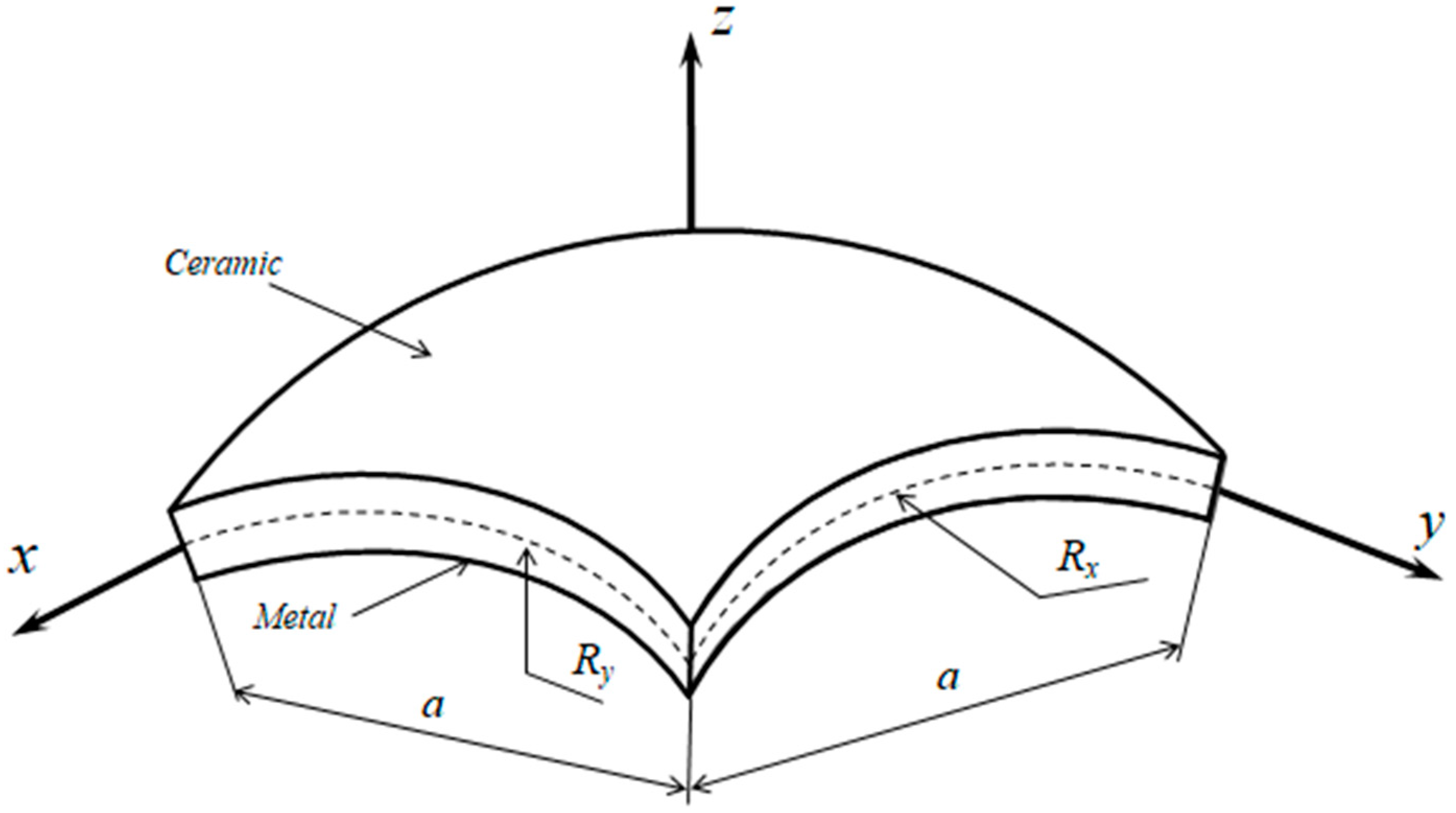
FGM is formed by a mixture of ceramic and metal, as shown in Figure 1. The material properties change continuously from a surface to the other surface according to a power–law of volume fraction
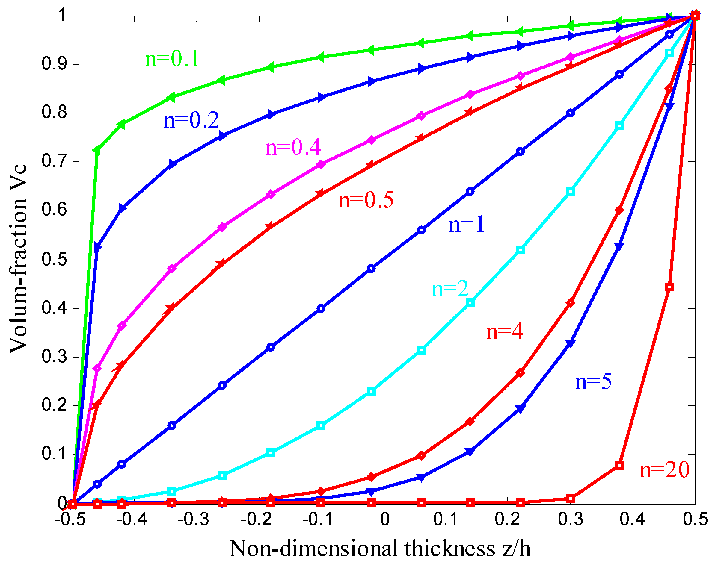
where represents the effective material properties: Young’s modulus , density and Poisson ratio ; and denote the properties of the ceramic and metal, respectively; is the volumefractions of the ceramic; the thickness of structure; the volumefraction exponent; is the thickness coordinate of the structure. Figure 2 illustrates the variation of the volume fraction of ceramic and metal through the thickness via the volumefraction exponent .
2.2. The FGM Shell Model
Consider an FGM shell element subjected to both in-plane forces and bending moments as shown in Figure 3. The middle (neutral) surface of the shell is chosen as the reference plane that occupies a domain . Let , and be the displacements of the middle plane in the , and directions; , and be the rotations of the middle surface of the shell around the -axis, -axis, and -axis, respectively, as indicated in Figure 3. The unknown vector of an FGM shell including six independent variables at any point in the problem domain can be written as
The linear strain–displacement relationship can be given as
From Hooke’s law, the constitutive relations of FGM shells are expressed as:
where
A weak form of the free vibration analysis for FGM shells can be briefly given as:
where
In which
In Equation (11) , , , and are given by:
where is transverse shear correction coefficient and is the mass matrix containing calculated as
2.3. Finite Element Formulation for Shell Analysis
Now, we discretize the bounded domain into finite three-node triangular elements with nodes such that and , . The displacement field of the finite element solution can be expressed as
where is the nodal displacement at the node; is shape function for the node.
The approximation of the membrane, the bending and the shear strains of the triangular element can be written in matrix forms as follows
where
By substituting the discrete displacement field into Equation (9) the discretized equation for free vibration analysis can be written into matrix form such as
where is the natural frequency, and are the global stiffness and mass matrices, respectively,
with
and
in which is the transformation matrix between the local coordinate system and the global coordinate system [14].
The problem of zero stiffness that appears with using the drilling degree of freedom , which can cause a singularity in the global stiffness matrix when all the elements meeting at a node are coplanar. To deal with this issue, a simple modification coefficient is chosen to be times the maximum diagonal value of the element stiffness matrix at the zero drilling degree of freedom to avoid the drill rotation locking [15].
3. Formulation of ES-MITC3 Finite Element Method for FGM Shells
3.1. Brief on the MITC3 Formulation
In the linear triangular MITC3, the approximated displacement field is simply interpolated using the linear basic functions for membrane, deflection, and rotation without adding any new variables. Herein, the membrane and bending strains of the standard finite elements are unchanged, while the transverse shearstrains, which are modified by the mixed interpolation of tensorial components [16].
3.2. The ES-MITC3 Formulation
In the ES-FEM, the strains are smoothed over local smoothing domains , the computation for stiffness matrix is no longer based on elements, but on these smoothing domains. These smoothing domains are formed based on edge of elements such as and for , in which is the total number of edges of all the elements. On a curved geometry of shell models, an edge-based smoothing domain associated with the inner edge is created two sub-domains of two non-planar adjacent MITC3 triangular elements as shown in Figure 5. These triangular elements are defined by two local coordinate systems and . In order to compute the edge-based smoothing strain for two non-planar adjacent elements, the virtual coordinate system is proposed as shown in Figure 6, whereas the -axis coinciding with the edge , the -axis with the average direction between the -axis and -axis, and the -axis is given by the cross-product of the unit vectors in the -axis and -axis.
Hence, a smoothed membrane strain , a smoothed bending strain , a smoothed shearstrain of the smoothing domain in the global coordinate system can be derived as
where is the number of the neighboring nodes of edge . is the nodal degrees of freedom at the jth node of the smoothing domain in . , , and are the membrane, the bending and the MITC3 shear smoothed gradient matrices at the jth node of the smoothing domain in the global coordinate system , respectively. The , and can be computed by
in which , , and are strain transformation matrices between the global coordinate system and the virtual coordinate system , respectively; , and are the strain transformation matrices between the local coordinate system of ith adjacent triangular elements and the virtual coordinate system , respectively; is the transformation matrix between the local coordinate system at the jth node of the ith adjacent triangular element and the global coordinate system . More detailed information about these strain transformation matrices can be found in [14]. The area of the smoothing domain is computed by
where is the number of the adjacent triangular elements in the smoothing domain , and is the area of the ith triangular element around the edge k.
As a result, the global stiffness matrix of the FGM shell in Equation (22) is rewritten as
where
with
4. Numerical Results
In the section, several numerical examples are provided to show the performance of the ES-MITC3 element for free vibration analysis of FGM shell and results obtained are compared to those published [6,16,17,18,19]. For convenience to the numerical comparison, the non-dimensional frequency parameters are expressed to the following equation as
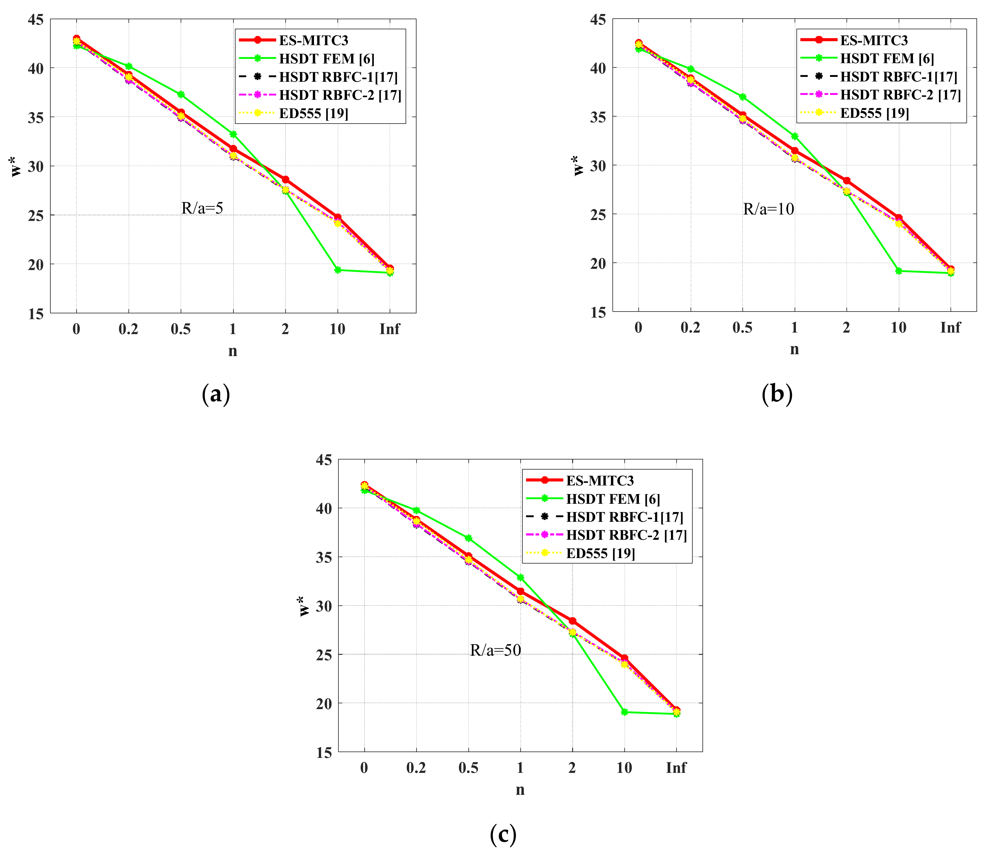
First, let us consider free vibration for analysis of clamped functionally graded cylindrical shell () with radius-to-length , . The functionally graded shell is made from Silicon nitride (Si3N4) and Stainless steel (SUS304), which material properties are GPa, , , GPa, , and . The first four non-dimensional frequency of the present method list in Table 1 are compared with MITC3 [16], a higher-order theory based on radial basis functions collocation including transverse normal deformation (HSDT RBFC-1) and discarding transverse normal deformation (HSDT RBFC-2) by Neves et al. [17], a higher-order theory and finite element formalation (HSDT FEM) by Pradyumna and Bandyopadhyay [6], a higher-order theory and semi-analytical method relied on Galerkin (HSDT SAG) by Yang and Shen [18], and Quasi-3D Ritz model (ED555) by Fazzolari and Carrera [19]. From Table 1 we can see that this proposed method (ES-MITC3) is more accurate than other methods, such as MITC3, HSDT RBFC-1, HSDT RBFC-2, HSDT FEM and HSDT SAG. The errors are less than 3% in comparison with the exact solution ED555 [19]. Figure 7 shows non-dimensional frequency parameter for four first modes of clamped functionally graded cylindrical shell using various methods.
Next, we investigate the first non-dimensional frequencies ω*.
of functionally graded spherical () and cylindrical shells () with geometric data: radius to edge and are varied from 5 to 50 and 10, respectively. The functionally graded shells in these studies are made from aluminum, and alumina whose material properties are , GPa, , , GPa, , and . Again, it is seen from Table 2, Table 3, Table 4 and Table 5 that the results of the present approach are very close to an HSDT RBFC-1, HSDT RBFC-2 [17], and ED555 [19]. Figure 8, Figure 9, Figure 10 and Figure 11 show non-dimensional frequency parameter for the first mode of cylindrical FGM shell and spherical FGM shell with different n, respectively. The first six mode shapes of simply supported spherical FGM shell are illustrated in Figure 12.
For the fully clamped spherical shell, the second vibration mode shape and the third vibration mode shape are similar to each other (their natural frequencies are equal), they just have different views. Adding, the value of non-dimensional frequency of the fifth and the sixth vibration mode shape are approximatively each other. This thing is consistent with the actual symmetrical shell structures with the same boundary conditions.
5. Conclusions
In this paper, the free vibration analysis of functionally graded shells is studied by using the ES-MITC3. Herein, the stiffness matrices obtained based on the strain-smoothing technique over the smoothing domains associated with edges of MITC3 shell elements. The present approach uses a triangular element and hence much easily generated automatically, even for complicated geometries. The numerical results showed that the ES-MITC3 is a good agreement with the reference solutions, which are a requirement of high computational costs, such as ED555 [19] and a higher-order theory based on radial basis functions [17]. The ES-MITC3 presented herein is promising to be a simple and effective finite element method for analysis of functionally graded shells in practice.
The combination of finite element method (FEM) with an edge-based smoothed finite element method (ES-FEM) is very suitable for analyzing shell structures, especially for the complicated structures such as shell with reinforced stiffeners, reinforced nano grapheme, micro shell structures, nano shell structures, and so on. This combination allows us to calculate exactly plate and shell structures with thin thicknesses (h = a/108) due to overcoming the shear locking phenomenon.
Author Contributions
Investigation, Q.H.P.; Software, Q.H.P. and T.D.P.; Visualization, V.D.P.; Writing—original draft, V.T.D.; Writing—review & editing, H.-N.N.
Funding
This research was funded by Vietnam National Foundation for Science and Technology Development (NAFOSTED) grant number 107.02-2018.30.
Conflicts of Interest
The authors declare no conflict of interest.
References
- Woo, J.; Meguid, S. Nonlinear analysis of functionally graded plates and shallow shells. Int. J. Solids Struct. 2001, 38, 7409–7421. [Google Scholar] [CrossRef]
- Matsunaga, H. Free vibration and stability of functionally graded shallow shells according to a 2D higher-order deformation theory. Compos. Struct. 2008, 84, 132–146. [Google Scholar] [CrossRef]
- Duc, N.D.; Quan, T.Q.; Luat, V.D. Nonlinear dynamic analysis and vibration of shear deformable piezoelectric FGM double curved shallow shells under damping-thermo-electro-mechanical loads. Compos. Struct. 2015, 125, 29–40. [Google Scholar] [CrossRef]
- Bich, D.H.; Duc, N.D.; Quan, T.Q. Nonlinear vibration of imperfect eccentrically stiffened functionally graded double curved shallow shells resting on elastic foundation using the first order shear deformation theory. Int. J. Mech. Sci. 2014, 80, 16–28. [Google Scholar] [CrossRef]
- Arciniega, R.A.; Reddy, J.N. Large deformation analysis of functionally graded shells. Int. J. Solids Struct. 2007, 44, 2036–2052. [Google Scholar] [CrossRef]
- Pradyumna, S.; Bandyopadhyay, J.N. Free vibration analysis of functionally graded curved panels using a higher-order finite element formulation. J. Sound Vib. 2008, 318, 176–192. [Google Scholar] [CrossRef]
- Kordkheili, S.A.H.; Naghdabadi, R. Geometrically non-linear thermoelastic analysis of functionally graded shells using finite element method. Int. J. Numer. Methods Eng. 2007, 72, 964–986. [Google Scholar] [CrossRef]
- Chau-Dinh, T.; Nguyen-Duy, Q.; Nguyen-Xuan, H. Improvement on MITC3 plate finite element using edge-based strain smoothing enhancement for plate analysis. Acta Mech. 2017, 228, 2141–2163. [Google Scholar] [CrossRef]
- Nguyen, T.-K.; Nguyen, V.-H.; Chau-Dinh, T.; Vo, T.P.; Nguyen-Xuan, H. Static and vibration analysis of isotropic and functionally graded sandwich plates using an edge-based MITC3 finite elements. Compos. Part B Eng. 2016, 107, 162–173. [Google Scholar] [CrossRef]
- Pham, Q.-H.; Tran, T.-V.; Pham, T.-D.; Phan, D.-H. An Edge-Based Smoothed MITC3 (ES-MITC3) Shell Finite Element in Laminated Composite Shell Structures Analysis. Int. J. Comput. Methods 2017, 15, 1850060. [Google Scholar] [CrossRef]
- Pham, Q.-H.; Pham, T.-D.; Trinh, Q.V.; Phan, D.-H. Geometrically nonlinear analysis of functionally graded shells using an edge-based smoothed MITC3 (ES-MITC3) finite elements. Eng. Comput. 2019, 1–14. [Google Scholar] [CrossRef]
- Pham-Tien, D.; Pham-Quoc, H.; Vu-Khac, T.; Nguyen-Van, N. Transient Analysis of Laminated Composite Shells Using an Edge-Based Smoothed Finite Element Method. In Proceedings of the International Conference on Advances in Computational Mechanics, Phu Quoc Island, Vietnam, 2–4 August 2017; pp. 1075–1094. [Google Scholar]
- Nguyen, H.N.; Canh, T.N.; Thanh, T.T.; Ke, T.V.; Phan, V.D.; Thom, D.V. Finite Element Modelling of a Composite Shell with Shear Connectors. Symmetry 2019, 11, 527. [Google Scholar] [CrossRef]
- Nguyen-Hoang, S.; Phung-Van, P.; Natarajan, S.; Kim, H.-G. A combined scheme of edge-based and node-based smoothed finite element methods for Reissner–Mindlin flat shells. Eng. Comput. 2016, 32, 267–284. [Google Scholar] [CrossRef]
- Nguyen-Thoi, T.; Phung-Van, P.; Thai-Hoang, C.; Nguyen-Xuan, H. A cell-based smoothed discrete shear gap method (CS-DSG3) using triangular elements for static and free vibration analyses of shell structures. Int. J. Mech. Sci. 2013, 74, 32–45. [Google Scholar] [CrossRef]
- Lee, P.-S.; Bathe, K.-J. Development of MITC isotropic triangular shell finite elements. Comput. Struct. 2004, 82, 945–962. [Google Scholar] [CrossRef]
- Neves, A.; Ferreira, A.; Carrera, E.; Cinefra, M.; Roque, C.; Jorge, R.; Soares, C.; Ferreira, A.; Jorge, R.N.; Soares, C.M.M. Free vibration analysis of functionally graded shells by a higher-order shear deformation theory and radial basis functions collocation, accounting for through-the-thickness deformations. Eur. J. Mech. A/Solids 2013, 37, 24–34. [Google Scholar] [CrossRef]
- Yang, J.; Shen, H.-S. Free vibration and parametric resonance of shear deformable functionally graded cylindrical panels. J. Sound Vib. 2003, 261, 871–893. [Google Scholar] [CrossRef]
- Fazzolari, F.A.; Carrera, E. Refined hierarchical kinematics quasi-3D Ritz models for free vibration analysis of doubly curved FGM shells and sandwich shells with FGM core. J. Sound Vib. 2014, 333, 1485–1508. [Google Scholar] [CrossRef]
Figure 1.
A functionally graded shell.

Figure 2.
Variation of the volume fraction versus the non-dimensional thickness.

Figure 3.
Three-node triangular element.

Figure 4.
Three-node triangular element and local coordinates.

Figure 5.
The smoothing domain; is formed by triangular elements.

Figure 6.
Global, local, and virtual coordinates.

Figure 7.
Non-dimensional frequency parameter for four first modes. (a) Mode 1; (b) mode 2; (c) mode 3; (d) mode 4.
Figure 7.
Non-dimensional frequency parameter for four first modes. (a) Mode 1; (b) mode 2; (c) mode 3; (d) mode 4.

Figure 8.
Non-dimensional frequency parameter for the first mode of clamped cylindrical FGM shell with different n. (a) R/a = 5; (b) R/a = 10; (c) R/a = 50.
Figure 8.
Non-dimensional frequency parameter for the first mode of clamped cylindrical FGM shell with different n. (a) R/a = 5; (b) R/a = 10; (c) R/a = 50.

Figure 9.
Non-dimensional frequency parameter for the first mode of simple supported cylindrical FGM shell with different n. (a) R/a = 5; (b) R/a = 10; (c) R/a = 50.
Figure 9.
Non-dimensional frequency parameter for the first mode of simple supported cylindrical FGM shell with different n. (a) R/a = 5; (b) R/a = 10; (c) R/a = 50.

Figure 10.
Non-dimensional frequency parameter for the first mode of simply supported spherical FGM shell with different n. (a) R/a = 5; (b) R/a = 10; (c) R/a = 50.
Figure 10.
Non-dimensional frequency parameter for the first mode of simply supported spherical FGM shell with different n. (a) R/a = 5; (b) R/a = 10; (c) R/a = 50.

Figure 11.
Non-dimensional frequency parameter for the first mode of clamped spherical FGM shell with different n. (a) R/a = 5; (b) R/a = 10; (c) R/a = 50.
Figure 11.
Non-dimensional frequency parameter for the first mode of clamped spherical FGM shell with different n. (a) R/a = 5; (b) R/a = 10; (c) R/a = 50.

Figure 12.
First six mode shapes of simply supported spherical FGM shell (R/a = 10, a/h = 10, n = 0.2).
Figure 12.
First six mode shapes of simply supported spherical FGM shell (R/a = 10, a/h = 10, n = 0.2).


Table 1.
Non-dimensional frequency parameter for clamped cylindrical functionally graded materials (FGM) shell with , and relative error between methods (ED555 [19] is fixed). .
Table 1.
Non-dimensional frequency parameter for clamped cylindrical functionally graded materials (FGM) shell with , and relative error between methods (ED555 [19] is fixed). .
| Mode | Method | n | ||||
|---|---|---|---|---|---|---|
| 0 | 0.2 | 2 | 10 | |||
| 1 | ES-MITC3 | 75.4587 | 61.3587 | 40.9880 | 35.3951 | 33.0594 |
| % | 0.2776 | 0.0298 | 0.3963 | 0.7275 | 0.5532 | |
| MITC3 [16] | 72.7508 | 59.0689 | 39.4771 | 34.0744 | 31.8220 | |
| % | 3.3209 | 3.7031 | 4.0679 | 4.4317 | 4.2754 | |
| HSDT FEM [6] | 72.9613 | 60.0269 | 39.1457 | 33.3666 | 32.0274 | |
| % | 3.0412 | 2.1413 | 4.8733 | 6.4169 | 3.6576 | |
| HSDT RBFC-1 [17] | 74.2634 | 60.0061 | 40.5259 | 35.1663 | 32.6108 | |
| % | 1.3108 | 2.1752 | 1.5193 | 1.3693 | 1.9026 | |
| HSDT RBFC-2 [17] | 74.5821 | 60.3431 | 40.8262 | 35.4229 | 32.8593 | |
| % | 0.8873 | 1.6258 | 0.7895 | 0.6496 | 1.1551 | |
| HSDT SAG [18] | 74.5180 | 57.4790 | 40.7500 | 35.8520 | 32.7610 | |
| % | 0.9725 | 6.2950 | 0.9747 | 0.5539 | 1.4508 | |
| ED555 [19] | 75.2498 | 61.3404 | 41.1511 | 35.6545 | 33.2433 | |
| 2 | ES-MITC3 | 144.4760 | 117.6462 | 78.5402 | 67.7320 | 63.3473 |
| % | 0.6724 | 0.6147 | 0.5174 | 0.3138 | 0.4088 | |
| MITC3 [16] | 140.8063 | 114.5113 | 76.4785 | 65.9309 | 61.6559 | |
| % | 1.8847 | 2.0664 | 2.1212 | 2.3537 | 2.2722 | |
| HSDT FEM [6] | 138.5552 | 113.8806 | 74.2915 | 63.2869 | 60.5546 | |
| % | 3.4533 | 2.6058 | 4.9201 | 6.2695 | 4.0178 | |
| HSDT RBFC-1 [17] | 141.6779 | 114.3788 | 76.9725 | 66.6482 | 61.9329 | |
| % | 1.2773 | 2.1797 | 1.4889 | 1.2913 | 1.8331 | |
| HSDT RBFC-2 [17] | 142.4281 | 115.2134 | 77.6639 | 67.1883 | 62.4886 | |
| % | 0.7546 | 1.4660 | 0.6041 | 0.4914 | 0.9523 | |
| HSDT SAG [18] | 144.6630 | 111.7170 | 78.8170 | 69.0750 | 63.3140 | |
| % | 0.8027 | 4.4562 | 0.8717 | 2.3029 | 0.3560 | |
| ED555 [19] | 143.5110 | 116.9275 | 78.1359 | 67.5201 | 63.0894 | |
| 3 | ES-MITC3 | 145.1510 | 118.1985 | 78.9069 | 68.0474 | 63.6440 |
| % | 1.0284 | 0.9602 | 0.8727 | 2.2434 | 0.7658 | |
| MITC3 [16] | 141.7861 | 115.3112 | 77.0122 | 66.3906 | 62.0864 | |
| % | 1.3137 | 1.5061 | 1.5494 | 4.6235 | 1.7003 | |
| HSDT FEM [6] | 138.5552 | 114.0266 | 74.3868 | 63.3668 | 60.6302 | |
| % | 3.5625 | 2.6033 | 4.9056 | 8.9675 | 4.0058 | |
| HSDT RBFC-1 [17] | 141.8485 | 114.5495 | 77.0818 | 66.7332 | 62.0082 | |
| % | 1.2702 | 2.1567 | 1.4604 | 4.1314 | 1.8241 | |
| HSDT RBFC-2 [6] | 142.6024 | 115.3665 | 77.7541 | 67.2689 | 62.5668 | |
| % | 0.7455 | 1.4588 | 0.6010 | 3.3618 | 0.9397 | |
| HSDT SAG [18] | 145.7400 | 112.5310 | 79.4070 | 67.5946 | 63.8060 | |
| % | 1.4383 | 3.8808 | 1.5121 | 2.8939 | 1.0223 | |
| ED555 [19] | 143.6735 | 117.0744 | 78.2242 | 69.6090 | 63.1603 | |
| 4 | ES-MITC3 | 204.0647 | 166.3177 | 111.0461 | 95.6539 | 89.5229 |
| % | 1.1780 | 1.2302 | 1.3863 | 1.2447 | 1.2996 | |
| MITC3 [16] | 195.3261 | 158.8135 | 106.1329 | 91.3802 | 85.4901 | |
| % | 3.1547 | 3.3373 | 3.0995 | 3.2788 | 3.2637 | |
| HSDT FEM [6] | 195.5366 | 160.6235 | 104.7687 | 89.1970 | 85.1788 | |
| % | 3.0503 | 2.2357 | 4.3450 | 5.5896 | 3.6160 | |
| HSDT RBFC-1 [17] | 199.1566 | 160.7355 | 107.9484 | 93.3350 | 86.8160 | |
| % | 1.2555 | 2.1675 | 1.4419 | 1.2097 | 1.7634 | |
| HSDT RBFC-2 [17] | 200.3158 | 162.0337 | 108.9677 | 94.0923 | 87.6341 | |
| % | 0.6808 | 1.3773 | 0.5113 | 0.4081 | 0.8377 | |
| HSDT SAG [18] | 206.9920 | 159.8550 | 112.4570 | 98.3860 | 90.3700 | |
| % | 2.6294 | 2.7034 | 2.6745 | 4.1365 | 2.2581 | |
| ED555 [19] | 201.6888 | 164.2966 | 109.5277 | 94.4779 | 88.3744 | |
Table 2.
Non-dimensional frequency parameter for clamped cylindrical FGM shell with and different ratios.
Table 2.
Non-dimensional frequency parameter for clamped cylindrical FGM shell with and different ratios.
| Method | n | |||||||
|---|---|---|---|---|---|---|---|---|
| 0 | 0.2 | 0.5 | 1 | 2 | 10 | |||
| 5 | ES-MITC3 | 73.4741 | 67.2928 | 60.6591 | 53.9842 | 48.1650 | 41.4718 | 33.4122 |
| HSDT FEM [6] | 71.8861 | 68.1152 | 63.1896 | 56.5546 | 36.2487 | 33.6611 | 32.4802 | |
| HSDT RBFC-1 [17] | 73.1640 | 66.6620 | 60.2477 | 53.5430 | 47.5205 | 40.8099 | 33.0576 | |
| HSDT RBFC-2 [17] | 73.6436 | 67.1004 | 60.6568 | 53.9340 | 47.9060 | 41.0985 | 33.2743 | |
| 10 | ES-MITC3 | 72.6253 | 65.5578 | 60.0417 | 53.4874 | 47.7863 | 41.1837 | 33.0311 |
| HSDT FEM [6] | 71.0394 | 67.3320 | 62.4687 | 55.8911 | 35.6633 | 31.1474 | 32.0976 | |
| HSDT RBFC-1 [17] | 72.3304 | 65.8808 | 59.5215 | 52.8800 | 46.9447 | 40.4145 | 32.6810 | |
| HSDT RBFC-2 [17] | 72.8141 | 66.3235 | 59.9353 | 53.2759 | 47.3343 | 40.7046 | 32.8995 | |
| 50 | ES-MITC3 | 72.3439 | 66.3519 | 59.9114 | 53.4282 | 47.7802 | 41.1529 | 32.9058 |
| HSDT FEM [6] | 70.7660 | 67.0801 | 62.2380 | 55.6799 | 35.4745 | 32.9812 | 31.9741 | |
| HSDT RBFC-1 [17] | 72.0614 | 65.6371 | 59.3022 | 52.6864 | 46.7820 | 40.3028 | 32.5594 | |
| HSDT RBFC-2 [17] | 72.5465 | 66.0814 | 59.7178 | 53.0841 | 47.1726 | 40.5923 | 32.7786 | |
Table 3.
Non-dimensional frequency parameter for simply supported cylindrical FGM shell with and different ratios.
Table 3.
Non-dimensional frequency parameter for simply supported cylindrical FGM shell with and different ratios.
| Method | n | |||||||
|---|---|---|---|---|---|---|---|---|
| 0 | 0.2 | 0.5 | 1 | 2 | 10 | |||
| 5 | ES-MITC3 | 42.9913 | 39.3028 | 35.4690 | 31.7485 | 28.6106 | 24.7564 | 19.5592 |
| HSDT FEM [6] | 42.2543 | 40.1621 | 37.2870 | 33.2268 | 27.4449 | 19.3892 | 19.0917 | |
| HSDT RBFC-1 [17] | 42.6701 | 38.7168 | 34.8768 | 30.9306 | 27.5362 | 24.2472 | 19.2796 | |
| HSDT RBFC-2 [17] | 42.7172 | 38.7646 | 34.9273 | 30.9865 | 27.5977 | 24.2839 | 19.3008 | |
| ED555 [19] | 42.7160 | 39.0642 | 35.0811 | 31.0414 | 27.5634 | 24.1245 | 19.3003 | |
| 10 | ES-MITC3 | 42.5231 | 38.9004 | 35.1357 | 31.4868 | 28.4168 | 24.6061 | 19.3492 |
| HSDT FEM [6] | 41.9080 | 39.8472 | 36.9995 | 32.9585 | 27.1879 | 19.1562 | 18.9352 | |
| HSDT RBFC-1 [17] | 42.3153 | 38.3840 | 34.5672 | 30.6485 | 27.2979 | 24.1063 | 19.1193 | |
| HSDT RBFC-2 [17] | 42.3684 | 38.4368 | 34.6219 | 30.7077 | 27.3616 | 24.1444 | 19.1433 | |
| ED555 [19] | 42.3677 | 38.7377 | 34.7661 | 30.7621 | 27.3258 | 23.9848 | 19.1429 | |
| 50 | ES-MITC3 | 42.3669 | 38.7889 | 35.0696 | 31.4631 | 28.4233 | 24.5937 | 19.2798 |
| HSDT FEM [6] | 41.7963 | 39.7465 | 36.9088 | 32.8750 | 27.0961 | 19.0809 | 18.8848 | |
| HSDT RBFC-1 [17] | 42.2008 | 38.2842 | 34.4809 | 30.5759 | 27.2423 | 24.0762 | 19.0675 | |
| HSDT RBFC-2 [17] | 42.2560 | 38.3384 | 34.5365 | 30.6355 | 27.3055 | 24.1125 | 19.0924 | |
| ED555 [19] | 42.2553 | 38.6391 | 34.6904 | 30.6890 | 27.2682 | 23.9515 | 19.0922 | |
Table 4.
Non-dimensional frequency parameter for simply supported spherical FGM shell with and different ratios.
Table 4.
Non-dimensional frequency parameter for simply supported spherical FGM shell with and different ratios.
| Method | n | |||||||
|---|---|---|---|---|---|---|---|---|
| 0 | 0.2 | 0.5 | 1 | 2 | 10 | |||
| 5 | ES-MITC3 | 44.4405 | 40.6238 | 36.6449 | 32.7529 | 29.4124 | 25.2893 | 20.2096 |
| HSDT FEM [6] | 44.0073 | 41.7782 | 38.7731 | 34.6004 | 28.7459 | 20.4691 | 19.8838 | |
| HSDT RBFC-1 [17] | 44.4555 | 40.3936 | 36.4453 | 32.3691 | 28.7833 | 25.0772 | 20.0818 | |
| HSDT RBFC-2 [17] | 44.4697 | 40.4211 | 36.6004 | 32.4101 | 28.8329 | 25.1038 | 20.0927 | |
| ED555 [19] | 44.4671 | 40.7166 | 36.6297 | 32.4645 | 28.7996 | 24.9403 | 20.0915 | |
| 10 | ES-MITC3 | 42.9198 | 39.2373 | 35.4098 | 31.6957 | 28.5633 | 24.7153 | 19.5267 |
| HSDT FEM [6] | 42.3579 | 40.2608 | 37.3785 | 33.3080 | 27.5110 | 19.4357 | 19.1385 | |
| HSDT RBFC-1 [17] | 42.7709 | 38.8074 | 34.9574 | 31.0012 | 27.5984 | 24.3034 | 19.3251 | |
| HSDT RBFC-2 [17] | 42.8180 | 38.8551 | 35.0080 | 31.0572 | 27.6602 | 24.3401 | 19.3464 | |
| ED555 [19] | 42.8169 | 39.1556 | 35.1622 | 31.1122 | 27.6258 | 24.1803 | 19.3459 | |
| 50 | ES-MITC3 | 42.4046 | 38.8147 | 35.0835 | 31.4662 | 28.4197 | 24.5977 | 19.2966 |
| HSDT FEM [6] | 41.8145 | 39.7629 | 36.9234 | 32.8881 | 27.1085 | 19.0922 | 18.8930 | |
| HSDT RBFC-1 [17] | 42.2192 | 38.2988 | 34.4922 | 30.5840 | 27.2474 | 24.0791 | 19.0759 | |
| HSDT RBFC-2 [17] | 42.2741 | 38.3528 | 34.5478 | 30.6437 | 27.3109 | 24.1168 | 19.1006 | |
| ED555 [19] | 42.2735 | 38.6538 | 34.7018 | 30.6975 | 27.2741 | 23.9567 | 19.1004 | |
Table 5.
Non-dimensional frequency parameter for clamped spherical FGM shell with different ratios.
| Method | n | |||||||
|---|---|---|---|---|---|---|---|---|
| 0 | 0.2 | 0.5 | 1 | 2 | 10 | |||
| 5 | ES-MITC3 | 74.3416 | 68.0034 | 61.2122 | 54.3761 | 48.3922 | 41.5911 | 33.7972 |
| HSDT FEM [6] | 73.5550 | 69.6597 | 64.6114 | 57.8619 | 37.3914 | 34.6658 | 33.2343 | |
| HSDT RBFC-1 [17] | 74.8207 | 68.2142 | 61.6902 | 54.8597 | 48.6656 | 41.6016 | 33.8061 | |
| HSDT RBFC-2 [17] | 75.2810 | 68.6329 | 62.0789 | 55.2302 | 49.0328 | 41.8796 | 34.0141 | |
| 10 | ES-MITC3 | 72.8831 | 66.7331 | 60.1352 | 53.5040 | 47.7428 | 41.1652 | 33.1447 |
| HSDT FEM [6] | 71.4659 | 67.7257 | 62.8299 | 56.2222 | 35.9568 | 33.4057 | 32.2904 | |
| HSDT RBFC-1 [17] | 72.7536 | 66.2686 | 59.8745 | 53.1956 | 47.2135 | 40.5990 | 32.8722 | |
| HSDT RBFC-2 [17] | 73.2322 | 66.7063 | 60.2831 | 53.5864 | 47.5990 | 40.8883 | 33.0884 | |
| 50 | ES-MITC3 | 72.3889 | 66.3780 | 59.9190 | 53.4192 | 47.7612 | 41.1495 | 32.9258 |
| HSDT FEM [6] | 70.7832 | 67.0956 | 62.2519 | 55.6923 | 35.4861 | 32.9916 | 31.9819 | |
| HSDT RBFC-1 [17] | 72.0784 | 65.6498 | 59.3112 | 52.6921 | 46.7849 | 40.3049 | 32.5671 | |
| HSDT RBFC-2 [17] | 72.5633 | 66.0938 | 59.7265 | 53.0895 | 47.1574 | 40.5946 | 32.7862 | |
© 2019 by the authors. Licensee MDPI, Basel, Switzerland. This article is an open access article distributed under the terms and conditions of the Creative Commons Attribution (CC BY) license (http://creativecommons.org/licenses/by/4.0/).
Share and Cite
MDPI and ACS Style
Pham, T.D.; Pham, Q.H.; Phan, V.D.; Nguyen, H.N.; Do, V.T. Free Vibration Analysis of Functionally Graded Shells Using an Edge-Based Smoothed Finite Element Method. Symmetry 2019, 11, 684. https://doi.org/10.3390/sym11050684
AMA Style
Pham TD, Pham QH, Phan VD, Nguyen HN, Do VT. Free Vibration Analysis of Functionally Graded Shells Using an Edge-Based Smoothed Finite Element Method. Symmetry. 2019; 11(5):684. https://doi.org/10.3390/sym11050684
Chicago/Turabian StylePham, Tien Dat, Quoc Hoa Pham, Van Duc Phan, Hoang Nam Nguyen, and Van Thom Do. 2019. "Free Vibration Analysis of Functionally Graded Shells Using an Edge-Based Smoothed Finite Element Method" Symmetry 11, no. 5: 684. https://doi.org/10.3390/sym11050684
Note that from the first issue of 2016, this journal uses article numbers instead of page numbers. See further details here.