Controller for the Grid-Connected Microinverter Output Current Tracking


1
State Research Institute Center for Physical Sciences and Technology, Sauletekio av. 3, LT-10257 Vilnius, Lithuania
2
Institute of Regional Development, Siauliai University, P. Visinskio str. 25-402, LT-76351 Siauliai, Lithuania
3
Faculty of Electronics, Vilnius Gediminas Technical University, Naugarduko st. 41, 03227 Vilnius, Lithuania
*
Author to whom correspondence should be addressed.
Symmetry 2020, 12(1), 112; https://doi.org/10.3390/sym12010112
Submission received: 19 November 2019
/
Revised: 26 December 2019
/
Accepted: 2 January 2020
/
Published: 7 January 2020
Abstract
:The modification of the proportional–integral (PI) controller with the variable proportional constant for tracking of the grid-connected photovoltaic microinverter output current has been proposed. The obtained results show that in the case when the proportional constant of the PI controller varies in time according to the appropriate law, the microinverter output current sinus shape distortions decrease as compared to the case when the ordinary PI controller is used. The operation of the microinverter with the proposed controller was investigated for the cases when the electrical grid voltage sinus shape is not distorted and when it is distorted by the higher harmonics.
1. Introduction
Microinverters are designed for a single photovoltaic module with a power of 50–350 W and are increasingly used to convert the photovoltaic energy into the standard power grid energy in small scale grid-connected residential applications [1,2]. Microinverters can also be used in high power solar farms instead of centralized inverters. Their application in solar farms increases the efficiency of energy harvesting because the maximum power point tracking is performed individually for each module [1,2,3].
The grid-connected microinverter operates as a current source. Therefore, it is important to keep the shape of the grid-connected photovoltaic inverter output current as close as possible to the sinus to minimize the generation of higher harmonics [4,5,6,7]. Higher harmonics can be suppressed using traditional LC filters. However, passive filters are not efficient in removing harmonics [8,9,10,11,12,13]. It is more effective to include the feedback control system into the structure of the microinverter for tracking of the sinusoidal reference to guarantee the sinus shape of the output current and to minimize the steady-state error between the actual output current and the current reference [14,15,16,17,18].
The most popular controllers used for tracking of the grid-connected inverter output current are proportional–integral (PI) [19,20,21,22,23,24,25], proportional–integral–derivative (PID) [3,21,26,27], and proportional–resonant (PR) [2,15,21,28,29,30,31,32] controllers. However, more sophisticated predictive current controllers can be used as well [4,33,34].
The PI and PID controllers are usually employed in the industrial microinverters [29]. The popularity of these well-known controllers is determined by the easy implementation, efficiency, and well-developed tuning techniques of controller parameters [21]. The disadvantage of PI and PID controllers is that they cannot track the sinus reference signal without the steady-state error.
The transfer function of PR controller [32]:
where KP is the proportional constant, Kr is the resonant gain and ω is the resonant frequency. Theoretically, the PR controller is characterized by the infinite gain at the resonant frequency (for the standard electric grid ω = 314 rad/s) and, therefore, it should provide a zero steady-state error between the actual output current of the inverter and the current reference. However, the employment of the PR controller is challenging because there are no common tuning methods of controller parameters [32,35].
The predictive current controllers are more sophisticated as compared to the PI, PID, and PR controllers. The algorithm of the predictive current controller estimates the inverter output current value of the next switching cycle using the results of the previous cycle and provides a more precise control of the inverter output current and lower current shape distortions. However, the implementation of the predictive current controller is complicated and it requires a good understanding of the system parameters [4,33].
The authors of this work have found that when the proportional constant of the PI controller varies in time according to a certain law, the microinverter output current sinus shape distortions decrease as compared to the case when the ordinary PI controller is used. The novelty of this work is that a new modification of the PI controller with the variable proportional constant for tracking of the grid-connected photovoltaic microinverter output current has been proposed. This controller provides more effective suppression of higher harmonics as compared to ordinary PI controller. The operation of the proposed controller was investigated using it in the single stage photovoltaic microinverter based on a couple of two-switch DC-DC flyback converters. The photovoltaic grid-connected microinverter based on this topology [36,37], which was previously proposed by the authors of the paper, is characterized by the higher energy efficiency as compared to the microinverters with the traditional topology.
The obtained investigation results of the grid-connected photovoltaic microinverter using proposed modification of the PI controller are compared with these obtained using popular in microinverter applications ordinary PI controller. Matlab/Simulink (Mathworks; Natick, MA; USA) software was used for the investigation. Additionally, the experimental investigation of the proposed controller was performed.
The comparison of proposed controller with other more advanced controllers that can be used for current control, e.g., with proportional–resonant and predictive current controllers was not analyzed in this work because they are less popular in microinverter applications. On the other hand, it is self-evident without analysis that these controllers provide lower current distortions and lower steady-state error, but their implementation is more complicated [4,32,33,34,35].
2. Control System for Tracking of the Grid-Connected Microinverter Output Current
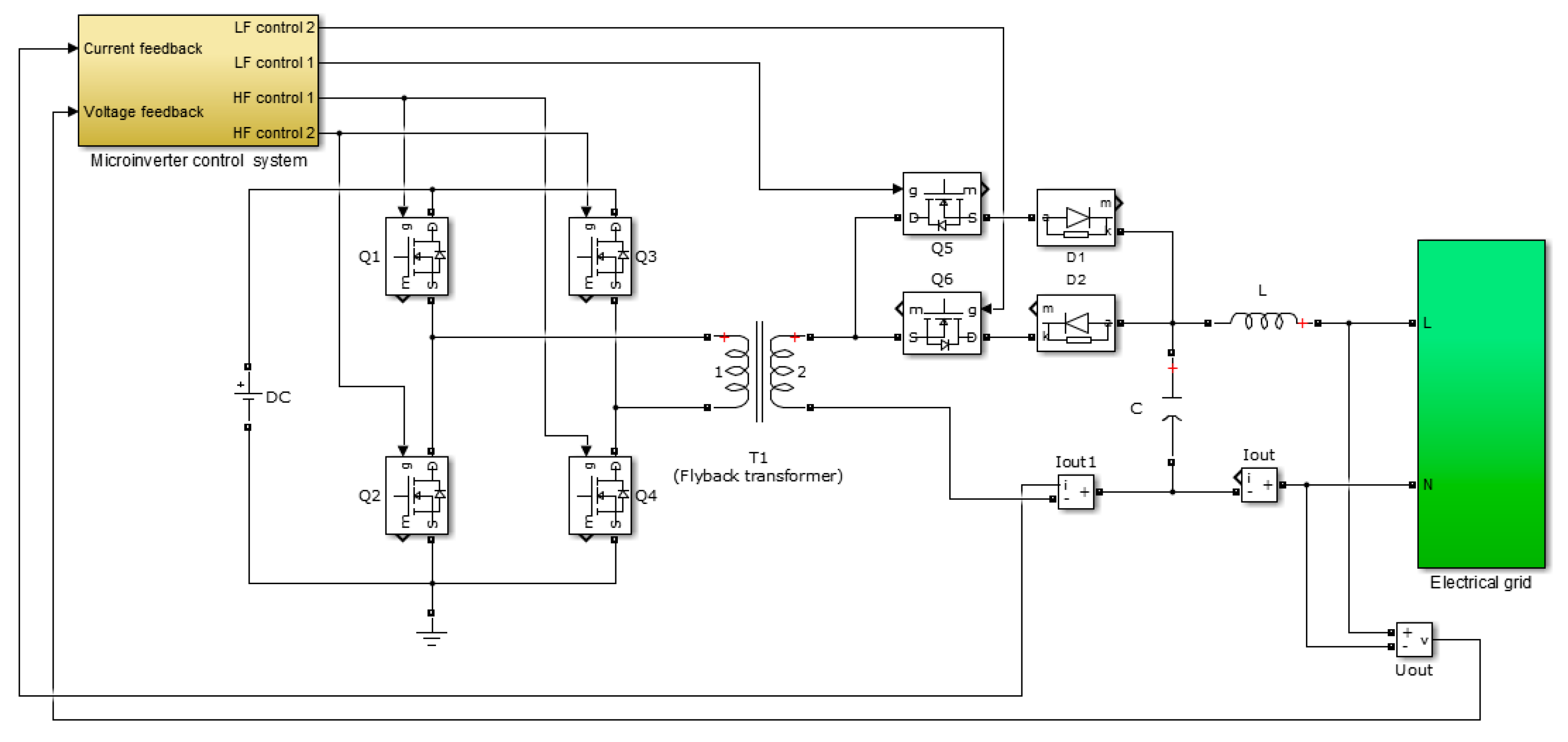
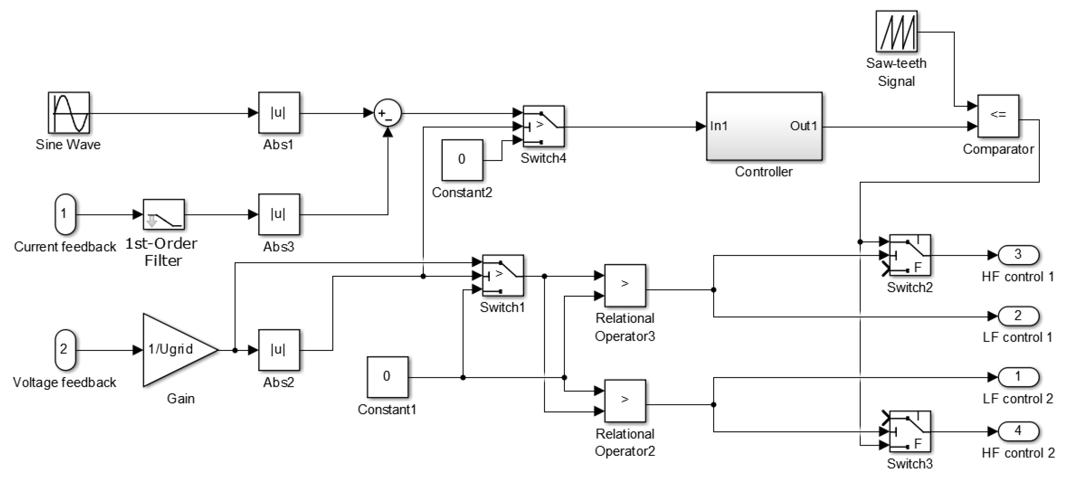
The block diagram of a single stage photovoltaic microinverter based on a couple of two-switch DC–DC flyback converters [36] is given in Figure 1. The feedback control system for tracking of the sinusoidal reference has to be used to effectively suppress the higher harmonics of the output current. The purpose of the control system is to form the pulse width modulation (PWM) signals for the control of the microinverter switches in such a way that the shape of the output current of the inverter would be as close as possible to the sinus. The proposed structure of the microinverter control system is given in Figure 2. It presents the feedback control system for tracking of the sinusoidal setup signal. The PWM signal is formed by the comparator circuit, which compares the controller output signal with the saw-teeth signal. The instantaneous duty cycle of the PWM signal can be found using the following equation:
where U(ti) is the controller output signal value at time moment ti, and UAst is the saw-tooth signal amplitude. The condition U(ti) ≤ UAst has to be satisfied.
The first order low-pass filter is employed in the current feedback circuit (Figure 2) to increase the stability of the controller operation under the influence of current ripples. The operation of the microinverter control system has to be synchronized with the mains power system. Therefore, the mains power system voltage phase has been observed using the voltage feedback circuit. The PWM signal provided by the comparator is conducted to the input HF control 1, i.e., to the switches Q1, Q4, and the potential that opens the switch Q5 is sent to the LF control 1 input (Figure 1) during the half period, at which the electric grid voltage is positive. During the negative half period the PWM signal has to be sent to the HF control 2 input (to switches Q2, Q3) and the potential that opens the transistor Q6—to the input LF control 2.
3. Analysis of the Microinverter Control System Based on the PI Controller
The behavior of the microinverter control system (Figure 2) based on the ordinary PI controller was analyzed. The output signal of this controller is:
where KP and KI are proportional and integral constants, t is time, t0 is the initial time, and e(t) is the control error that acts as the input signal of the controller.
The inverter control system has to provide the sinus shape of the microinverter output current tracking the sine setup signal. The phase of the inverter current has to coincide with the mains power system voltage phase. The performance of the investigated inverter control system depends not only on the control algorithm of the controller but on the active resistances and inductive resistances of flyback transformer windings and the magnetizing inductance. It depends on the parameters of the output CL filter as well.
The parameters of flyback transformer and CL filter are presented in Table 1.
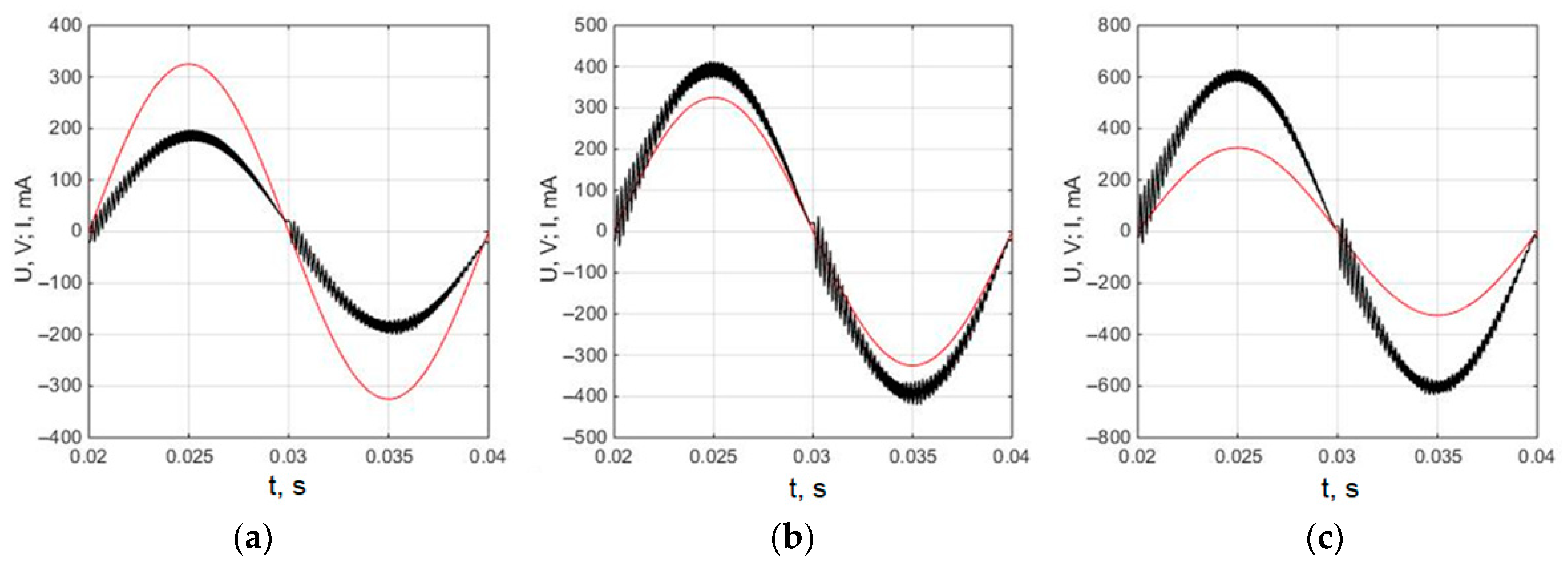
The parameters of the PI controller were adjusted for the minimal total harmonic distortion (THD) of inverter output current. The obtained values of PI controller parameters are as follows: KP = 10, KI = 15. The microinverter output current for the case when the electric grid voltage shape is not distorted is presented in Figure 3. The analysis was provided for the microinverter output current with 200 mA, 400 mA and 600 mA amplitude, that correspond to 32 W, 62 W, and 97 W power delivered to the grid, respectively. It is seen (Figure 3) that the shape of the inverter output current is close to the sine. However, the high-frequency ripples are seen on the current curve. It has been estimated that the amplitude of the ripples strongly depends on the value of the PI controller proportional constant KP. The ripples decrease if the value of KP decreases. However, the shape of the current worsens and the phase shift of current is introduced at low KP. All results presented in the work have been obtained for the 28 kHz switching frequency of inverter switches.
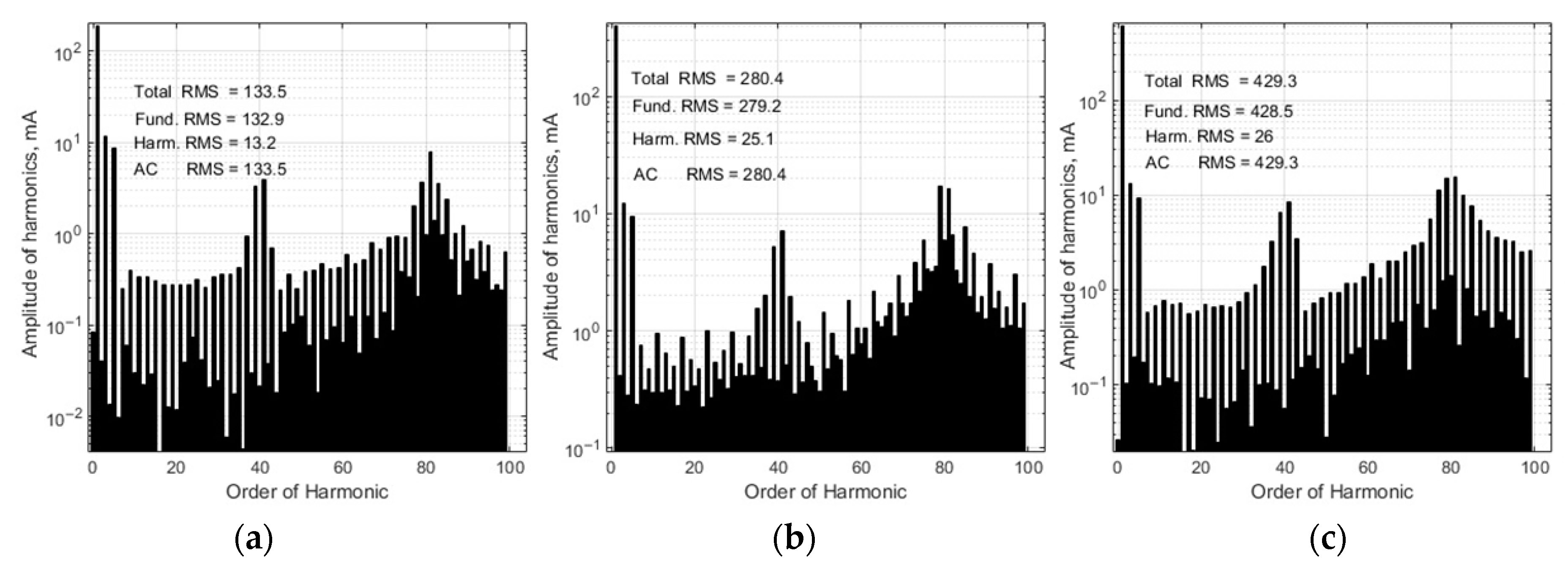
The microinverter output current spectra at the 32 W, 62 W, and 97 W load power obtained using the fast Fourier transform are given in Figure 4. It is seen that 37–43 and 79–83 harmonics are characterized by the highest amplitudes. The analysis of the harmonic spectrum shows that the THD, which is defined as the ratio of the root mean square (RMS) of the higher harmonics to the RMS of the fundamental 50 Hz harmonic, is 6.3% at 32 W, 6.6% at 62 W, and 5.5% at 97 W load power.
Figure 5 shows the analysis results of the microinverter output current when the electric grid voltage is distorted by third- and fifth-order harmonics. The curve of the grid voltage is described by the following equation:
where is the fundamental harmonic component of 325 V; is the third-order harmonic voltage component of 55 V; is the fifth-order harmonic voltage component of 55 V.
It is seen (Figure 5) that at the microinverter load of 32 W the asymmetry of the current half-cycle is observed. The asymmetry decreases with increasing of the load power and it becomes almost unnoticeable at the 97 W load of the microinverter.
The microinverter output current spectra at the 32 W, 62 W, and 97 W load power are given in Figure 6. Using the data presented in spectra, it can be estimated that the THD of the output current is 9.9% at 32 W, 8.9% at 62 W, and 6.1% at 97 W load power, i.e., the distortions are higher as compared to values (6.3%, 6.6%, and 5.5%, respectively) that were obtained for the case when the electric grid voltage was not distorted. Therefore, the conclusion can be drawn that the electric grid voltage shape distortion by third- and fifth-order harmonics increase the output current distortion and this increment is higher at lower load.
4. PI Controller with the Variable Proportional Constant
The simulation results (Figure 3 and Figure 5) show that the microinverter output current includes high-frequency ripples. The amplitude of the ripples depends on the aggressiveness of the proportional term of the PI controller, i.e., on the value of the proportional term KP. The amplitude of ripples decreases at lower KP. However, if KP is too low, the output current amplitude of the microinverter does not reach the set point value. If a higher value of KP is selected, the ripples of the microinverter output current increase. When evaluating the obtained results, one can assume that at a low current value that is close to zero it is more suitable to use a lower value of KP and at a high value that is close to the amplitude value it is necessary to select the value of KP higher.
Based on the conclusion made above, the assumption can be made that KP should be varied in proportion to the microinverter output current to reduce the ripples of the output current. The control algorithm of the suggested controller, which presents the PI controller with the variable proportional constant KP = KV(t) KC, is as follows:
where KV(t) and KC are the time-varying and the constant terms of the proportional constant, respectively. The simulation results of microinveter control system show that low distortions of the microinverter output current shape are reached when KV(t) during every half period of the current changes in time with the current by the similar law. It was found that the same results are obtained if instead of the pure sinus law its piecewise linear approximation given in Figure 7 is used for the variation of the KV(t). The piecewise linear approximation was used because it is easier to implement. Equation (6) presents the piecewise linear dependents given in Figure 7. The parameters of piecewise linear approximation of KV(t) were estimated by variation of approximation parameters by the criterion of minimal THD of microinverter output current.
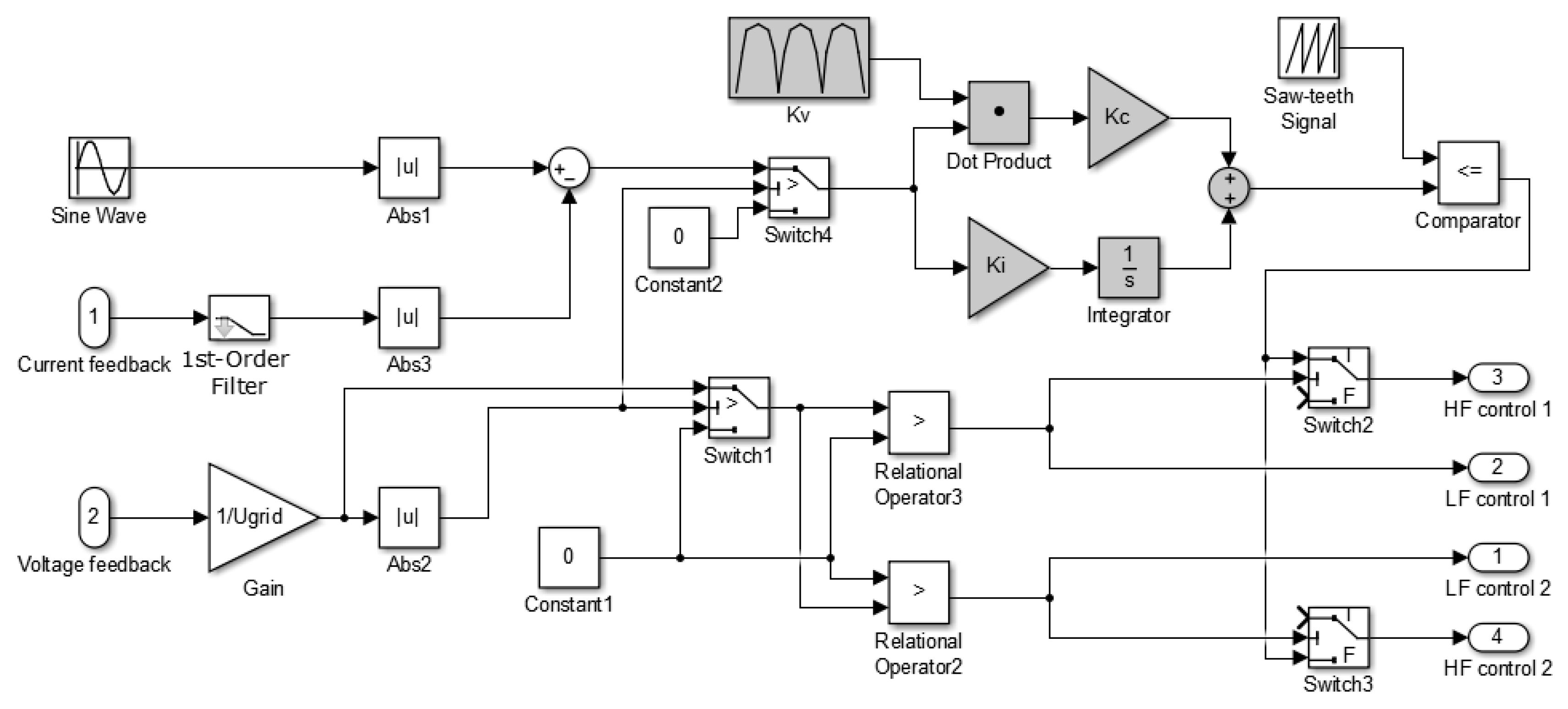
The block diagram of the microinverter control system based on the PI controller with the variable proportional constant created using Matlab/Simulink software is presented in Figure 8.
5. Analysis of the Microinverter Control System Based on the PI Controller with the Variable Proportional Constant
The operation of the microinverter control system based on the proposed PI controller with the variable proportional constant was analyzed at the 32 W, 62 W, and 97 W microinverter output power, which correspond to 200 mA, 400 mA, and 600 mA amplitudes of the microinverter load current, respectively.
The analyzed current trucking control system is nonlinear and the parameters of controller have to be adjusted for the minimal THD of inverter output current. Known classical PI controller tuning methods did not work in this case. The PI controller parameters can be tuned using optimization techniques in such a situation [38]. The univariate search method algorithm [39,40] was used for the tuning of controller parameters. This method is developed for the optimization of non-linear systems. During every iteration only one variable is varied to find its optimal value for the fixed initial values of another variables. After all variables are varied, the procedure is repeated again until the minimal (maximal) value of objective function is obtained.
The tuning aim of the proposed PI controller was to find the values of controller parameters KC and KI, at which the THD of the microinverter output current is minimal, i.e., the tuning leads to an optimization task with two variables. Using the univariate search method, the controller parameters were tuned as follows: at the fixed initial KC = KCi value, the KI = KIo1 value, at which the THD gets minimal, was obtained; at a fixed KI = KIo1 value, the KC = KCo1 value, at which the THD gets the minimum, was found. This process was repeated until the minimum THD value was obtained. The optimization procedure was also repeated with different initial KC = KCi values. The obtained values of parameters of PI controller with the variable proportional constant are as follows: KC = 10, KI = 15.
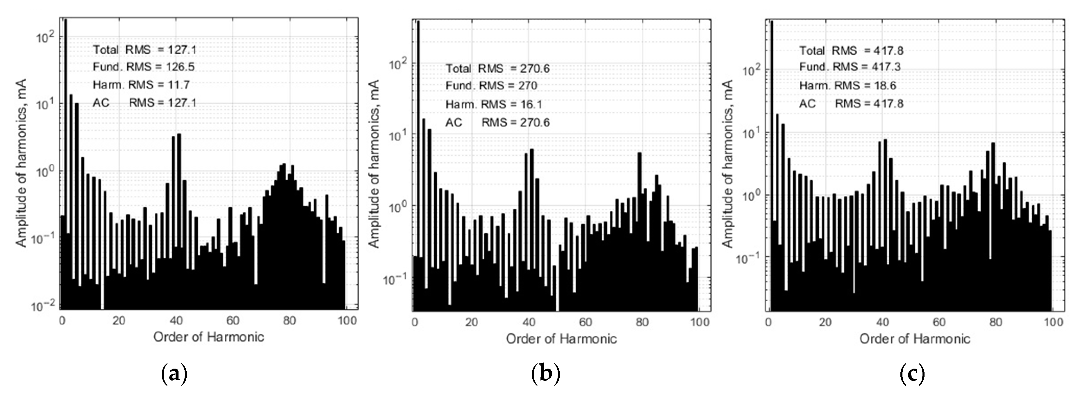
The microinverter output current and the grid voltage are presented in Figure 9. The obtained analysis results show that the employment of the proposed PI controller with the variable proportional constant allows us to reduce the high frequency ripples of the output current as compared with the case when the ordinary PI controller is used (compare current curves presented in Figure 9 with those given in Figure 3). The microinverter output current spectra at the 32 W, 62 W, and 97 W load power are given in Figure 10. Using the data presented in spectra, it can be estimated that the THD of the output current is 4.4% at 32 W, 3.4% at 62 W, and 3.3% at 97 W load power. The comparison of obtained THD values with these received for the case when the ordinary PI controller is used, showing that the employment of the proposed PI controller with the variable proportional constant allows us to reduce the THD of the microinverter output current by 30% at 32 W, by 48% at 62 W, and by 40% at 97 W load power.
The investigation of the inverter output current using the proposed controller was also performed, when the electrical grid voltage was distorted by the third- and fifth-order harmonics and it is described by Equation (4). The current curves are presented in Figure 11. The comparison of obtained curves with those given in Figure 5, shows that employment of the PI controller with the variable proportional constant allows us to reduce the high frequency ripples as compared to the case when the ordinary PI controller is used.
The microinverter output current spectra are presented in Figure 12. Using the data given in spectra, it can be estimated that the THD of the output current is 9.2% at 32 W, 6.0% at 62 W, and 4.5% at 97 W load power. Comparison of obtained THD values with these received for the case when the ordinary PI controller is used shows that employment of the proposed PI controller with the variable proportional constant allows us to reduce the THD of microinverter output current by 7% at 32 W, by 33% at 62 W, and by 26% at 97 W load power.
The experimental investigation of the proposed controller using it in the single stage photovoltaic grid-connected microinverter based on a couple of two-switch DC-DC flyback converters was performed. The circuit diagram of the microinverter output stage is given in Figure 1. The types and parameters of transistors and diodes used in the output stage of the experimental model are given in Table 2. The parameters of flyback transformer and CL filter are presented in Table 1. The control system was implemented using digital signal controller dsPIC33FJ16GS504. The experimentally obtained current curves for the cases when the proposed PI controller with the variable proportional constant and conventional PI controller were used are given in Figure 13. The investigation was performed at the 600 mA output current amplitude. It is seen that the control system based on the proposed controller provides lover ripples of the current as compared to the case when the ordinary PI controller is used. The high frequency ripples that appear on the experimentally obtained microinverter output current curves and are not observed in the simulated curves are caused by the measurement noise, which is introduced by electromagnetic disturbances generated by the output stage of the microinverter. The voltage shape of the investigated electric grid (red curves in Figure 13) is slightly distorted by the nonlinear grid loads.
There are lots of topologies used for the realization of microinverters. The purpose of this work was to develop and to investigate the controller for the grid-connected microinverter with the topology based on a couple of two-switch DC–DC flyback converters [36], which was previously proposed by the authors of this paper. Therefore, it can be stated that the proposed controller with the proportional constant that varies by the law as shown by Equation (6) is suitable for microinverters with this particular topology. The investigation of the controller applicability for the microinveters with the other topologies was beyond the scope of this work.
6. Conclusions
- The most popular controllers used for tracking of the grid-connected photovoltaic inverter output current in the industrial microinverters are PI and PID controllers.
- The distortions of the grid-connected microinverter output current shape can be reduced when the proportional constant of the PI controller during every half period of the current changes in time with the current by the similar law.
- The variation of the proportional constant in the proposed modification of the PI controller is realized by the introduction of the time-varying term, which varies according to the law presented by the piecewise linear approximation of the sinus.
- The employment of the proposed PI controller with the variable proportional constant for tracking of the grid-connected photovoltaic microinverter output current instead of the ordinary PI controller allows us to reduce the THD of the output current by 30% at 32 W, by 48% at 62 W, and by 40% at 97 W load power when the electric grid voltage has a pure sinus shape and by 7% at 32 W, by 33% at 62 W and by 26% at 97 W—in the case when the grid voltage is distorted by the third- and fifth-order harmonics.
- The experimental investigation results prove the superiority of the PI controller with the variable proportional constant over the ordinary PI controller.
- The implementation of the proposed controller is more complicated as compared to the ordinary PI controller because the proportional constant in the proposed controller varies in time according to a certain law.
Author Contributions
Conceptualization, A.B.; Investigation, E.B. and A.B.; Methodology, E.B.; Writing—review & editing, G.V. All authors have read and agreed to the published version of the manuscript.
Funding
This research received no external funding.
Conflicts of Interest
The authors declare no conflict of interest.
References
- Meneses, D.; Blaabjerg, F.; García, Ó.; Cobos, J.A. Review and Comparison of Step-Up Transformerless Topologies for Photovoltaic AC-Module Application. IEEE Trans. Power Electron. 2013, 28, 2649–2663. [Google Scholar] [CrossRef] [Green Version]
- Caiza, D.L.; Kouro, S.; Flores-Bahamonde, F.; Hernandez, R. Unfolding PV Microinverter Current Control: Rectified Sinusoidal vs Sinusoidal Reference Waveform. In Proceedings of the 2018 IEEE Energy Conversion Congress and Exposition, Portland, OR, USA, 23–27 September 2018; ISBN 978-1-4799-7312-5. [Google Scholar] [CrossRef]
- Yongjun, L.; Shun, W.; Jing, L.; Chen, C.; Weiliang, L. Grid-connected current control of micro inverter based on ANN inverse model. In Proceedings of the 2017 29th Chinese Control and Decision Conference, Chongqing, China, 28–30 May 2017; ISBN 978-1-5090-4657-7. [Google Scholar] [CrossRef]
- Kojabadi, H.M.; Yu, B.; Gadoura, I.A.; Chang, L.; Ghribi, M. A novel DSP-based current-controlled PWM strategy for single phase grid connected inverters. IEEE Trans. Power Electron. 2006, 21, 985–993. [Google Scholar] [CrossRef]
- Nan, W.; Shangsheng, L. Current output control strategy based on current reference feed-forward for H-bridge cascaded inverter. In Proceedings of the IECON 2017—43rd Annual Conference of the IEEE Industrial Electronics Society, Beijing, China, 29 October–1 November 2017; ISBN 978-1-5386-1127-2. [Google Scholar] [CrossRef]
- Suzuki, K.E.; Wada, K. Current Control using Pulsed Current Sampling Considering Sampling Points and Sensor Positions for Single-Phase Inverter. In Proceedings of the 2019 IEEE Applied Power Electronics Conference and Exposition (APEC), Anaheim, CA, USA, 17–21 March 2019; ISBN 978-1-5386-8330-9. [Google Scholar] [CrossRef]
- Xia, Y.; Ayyanar, R. Naturally Adaptive, Low-Loss Zero-Voltage-Transition Circuit for High-Frequency Full-Bridge Inverters with Hybrid PWM Grid-Tied Inverter. IEEE Trans. Power Electron. 2017, 33, 4916–4933. [Google Scholar] [CrossRef]
- Na, T.; Zhang, Q.; Tang, J.; Wang, J. Active power filter for single-phase Quasi-Z-source integrated on-board charger. CPSS Trans. Power Electron. Appl. 2018, 3, 197–201. [Google Scholar] [CrossRef]
- Wang, R.N.; Hu, B.; Sun, S. Linear Active Disturbance Rejection Control for DC Side Voltage of Single-Phase Active Power Filters. IEEE Access 2019, 7, 73095–73105. [Google Scholar] [CrossRef]
- Popescu, M.; Bitoleanu, A.; Preda, A. A New Design Method of an LCL Filter Applied in Active DC-Traction Substations. IEEE Trans. Ind. Appl. 2018, 55, 3497–3507. [Google Scholar] [CrossRef]
- Motta, L.; Faúndes, N. Active/passive harmonic filters: Applications, challenges & trends. In Proceedings of the 17th International Conference on Harmonics and Quality of Power (ICHQP), Belo Horizonte, Brazil, 16–19 October 2016. [Google Scholar] [CrossRef]
- Lee, T.-L.; Hu, S.-H. An Active Filter With Resonant Current Control to Suppress Harmonic Resonance in a Distribution Power System. IEEE J. Emerg. Sel. Top. Power Electron. 2016, 4, 198–209. [Google Scholar] [CrossRef]
- Nora, D.; Francisco, G.M.; Najib, A.; Yacine, D. A Hybrid Active Filter Using the Backstepping Controller for Harmonic Current Compensation. Symmetry 2019, 11, 1161. [Google Scholar] [CrossRef] [Green Version]
- Kazmierkowski, M.P.; Malesani, L. Current control techniques for three-phase voltage-source PWM converters: A survey. IEEE Trans. Ind. Electron. 1998, 45, 691–703. [Google Scholar] [CrossRef]
- Rajeev, M.; Agarwal, V. Analysis and Control of a Novel Transformer-Less Microinverter for PV-Grid Interface. IEEE J. Photovolt. 2018, 8, 1110–1118. [Google Scholar] [CrossRef]
- Xin, Z.; Mattavelli, P.; Yao, W. Mitigation of Grid-Current Distortion for LCL-Filtered Voltage-Source Inverter with Inverter-Current Feedback Control. IEEE Trans. Power Electron. 2017, 33, 6248–6261. [Google Scholar] [CrossRef]
- Bayhan, S.; Seyedalipour, S.S.; Komurcugil, H.; Abu-Rub, H. Lyapunov Energy Function Based Control Method for Three-Phase UPS Inverters with Output Voltage Feedback Loops. IEEE Access 2019, 7, 113699–113711. [Google Scholar] [CrossRef]
- Zha, Z.; Yang, J.; Li, S. Continuous Output Feedback TSM Control for Uncertain Systems With a DC–AC Inverter Example. IEEE Trans. Circuits Syst. Express Briefs 2017, 65, 71–75. [Google Scholar] [CrossRef]
- Dash, P.P.; Kazeran, M. Dynamic Modeling and Performance Analysis of a Grid-Connected Current-Source Inverter-Based Photovoltaic System. IEEE Trans. Sustain. Energy 2011, 2, 71–75. [Google Scholar] [CrossRef]
- Kamil, M. Grid-Connected Solar Microinverter Reference Design Using a dsPIC Digital Signal Controller. Available online: http://ww1.microchip.com/downloads/en/appnotes/pv_appnotes.pdf (accessed on 9 December 2019).
- Gazoli1, J.R.; Villalva, M.G.; Ruppert, E. Micro-inverter for integrated grid-tie photovoltaic module using resonant controller. In Proceedings of the 2012 IEEE Power and Energy Society General Meeting, San Diego, CA, USA, 22–26 July 2012; ISBN 978-1-4673-2729-9. [Google Scholar] [CrossRef]
- Hlali, M.; Bahri, I.; Belloumi, H.; Kourda, F. Comparative analysis of PI and PR based Current Controllers for Grid Connected Photovoltaic Micro-inverters. In Proceedings of the 2019 10th International Renewable Energy Congress, Sousse, Tunisia, 26–28 March 2019; ISBN 978-1-7281-0140-8. [Google Scholar] [CrossRef]
- Sahu, P.K.; Shaw, P.; Maity, S. Modeling and control of grid-connected DC/AC converters for single-phase micro-inverter application. In Proceedings of the 2015 Annual IEEE India Conference, New Delhi, India, 17–19 December 2015; ISBN 978-1-4673-7399-9. [Google Scholar] [CrossRef]
- Kim, H.; Yu, T.; Choi, S. Indirect Current Control Algorithm for Utility Interactive Inverters in Distributed Generation Systems. IEEE Trans. Power Electron. 2008, 23, 1342–1347. [Google Scholar] [CrossRef]
- Hassan, M.A.; Abido, M.A. Optimal Design of Microgrids in Autonomous and Grid-Connected Modes Using Particle Swarm Optimization. IEEE Trans. Power Electron. 2011, 26, 755–769. [Google Scholar] [CrossRef]
- Liu, C.; Zhang, H.-C. Photovoltaic Grid-connected Micro-inverter Based on Self-tuning Fuzzy-PI Controller. Adv. Mater. Res. 2014, 986, 1098–1102. [Google Scholar] [CrossRef]
- Wang, T.H.; Lo, Y.K. A DSP-based Grid-tied Solar Cascade-micra-inverter. In Proceedings of the 2013 1st International Future Energy Electronics Conference, Tainan, Taiwan, 3–6 November 2013; ISBN 978-1-4799-0073-2. [Google Scholar] [CrossRef]
- Melo, F.O.C.; Garcia, L.S.; De Freitas, L.C.; Coelho, E.A.A. Proposal of a Photovoltaic AC-Module with a Single-Stage Transformerless Grid-Connected Boost Microinverter. IEEE Trans. Ind. Electron. 2017, 65, 2289–2301. [Google Scholar] [CrossRef]
- Rodriguez, C.T.; Fuente, D.V.; Garcera, G. Reconfigurable Control Scheme for a PV Microinverter Working in Both Grid-Connected and Island Modes. IEEE Trans. Ind. Electron. 2011, 60, 1582–1595. [Google Scholar] [CrossRef]
- Shen, G.; Zhu, X.; Zhang, J.; Xu, D. A New Feedback Method for PR Current Control of LCL-Filter-Based Grid-Connected Inverter. IEEE Trans. Ind. Electron. 2010, 57, 2033–2041. [Google Scholar] [CrossRef]
- Liserre, M.; Teodorescu, R.; Blaabjerg, F. Stability of photovoltaic and wind turbine grid-connected inverters for a large set of grid impedance values. IEEE Trans. Power Electron. 2006, 21, 263–272. [Google Scholar] [CrossRef]
- Zhang, N.; Tang, H.; Yao, C. A Systematic Method for Designing a PR Controller and Active Damping of the LCL Filter for Single-Phase Grid-Connected PV Inverters. Energies 2014, 7, 3934–3954. [Google Scholar] [CrossRef]
- Bode, G.H.; Loh, P.C.; Newman, M.J.; Holmes, D.G. An improved robust predictive current regulation algorithm. IEEE Trans. Ind. Appl. 2005, 41, 1720–1733. [Google Scholar] [CrossRef]
- Mario, L.R.; Juan, G.; Francisco, V.M.F. Interactive Tuning Tool of Proportional-Integral Controllers for First Order Plus Time Delay Processes. Symmetry 2018, 10, 569. [Google Scholar] [CrossRef] [Green Version]
- Jayalath, S.; Hanif, M. Controller tuning for a single phase grid-connected current source inverter. In Proceedings of the 2015 IEEE 2nd International Future Energy Electronics Conference, Taipei, Taiwan, 1–4 November 2015; ISBN 978-1-4799-7657-7. [Google Scholar] [CrossRef]
- Bielskis, E.; Baskys, A.; Sapurov, M. Single Stage Microinverter Based on Two-Switch DC-DC Flyback Converter. Elektronika ir Elektrotechnika 2017, 23, 29–32. [Google Scholar] [CrossRef] [Green Version]
- Bielskis, E.; Baskys, A.; Sapurov, M. Impact of Transformer Design on Flyback Converter Voltage Spikes. Elektronika ir Elektrotechnika 2016, 22, 58–61. [Google Scholar] [CrossRef] [Green Version]
- Singh, B.; Joshi, N. Tuning Techniques of PID controller: A review. Int. J. Emerg. Technol. 2017, 8, 481–485. [Google Scholar]
- Al-Saleh, M.A.; Mir, M. A modified univariate search algorithm. In Proceedings of the 1999 IEEE International Symposium on Circuits and Systems, Orlando, FL, USA, 30 May–2 June 1999; ISBN 0-7803-5471-0. [Google Scholar] [CrossRef]
- Wilson, P.; Mantooth, H.A. Model-Based Engineering for Complex Electronic Systems; Newnes: Kidlington, UK, 2013; pp. 347–367. [Google Scholar]
Figure 1.
Block diagram of a single stage photovoltaic microinverter based on a couple of two-switch DC–DC flyback converters in the Matlab/Simulink environment.
Figure 1.
Block diagram of a single stage photovoltaic microinverter based on a couple of two-switch DC–DC flyback converters in the Matlab/Simulink environment.

Figure 2.
Microinverter control system in the Matlab/Simulink environment.

Figure 3.
The microinverter output current (black curves) when using the PI controller at different load power: (a) 32 W; (b) 62 W; (c) 97 W. Red curves represent the electric grid voltage.
Figure 3.
The microinverter output current (black curves) when using the PI controller at different load power: (a) 32 W; (b) 62 W; (c) 97 W. Red curves represent the electric grid voltage.

Figure 4.
Spectra of the output current of the microinverter based on the PI controller at the load power: (a) 32 W; (b) 62 W; (c) 97 W in the case when the electric grid voltage shape is not distorted.
Figure 4.
Spectra of the output current of the microinverter based on the PI controller at the load power: (a) 32 W; (b) 62 W; (c) 97 W in the case when the electric grid voltage shape is not distorted.

Figure 5.
The microinverter output current (black curves) when using the PI controller at a different load power: (a) 32 W; (b) 62 W; (c) 97 W. The electric grid voltage (red curves) is distorted by third- and fifth-order harmonics.
Figure 5.
The microinverter output current (black curves) when using the PI controller at a different load power: (a) 32 W; (b) 62 W; (c) 97 W. The electric grid voltage (red curves) is distorted by third- and fifth-order harmonics.

Figure 6.
Spectra of the output current of the microinverter based on the PI controller at the load power: (a) 32 W; (b) 62 W; (c) 97 W. The electric grid voltage is distorted by third- and fifth-order harmonics.
Figure 6.
Spectra of the output current of the microinverter based on the PI controller at the load power: (a) 32 W; (b) 62 W; (c) 97 W. The electric grid voltage is distorted by third- and fifth-order harmonics.

Figure 7.
The variation of time-varying constant KV(t) with time.

Figure 8.
The microinverter control system based on the PI controller with the variable proportional constant (the proposed PI controller is depicted with the darker background).
Figure 8.
The microinverter control system based on the PI controller with the variable proportional constant (the proposed PI controller is depicted with the darker background).

Figure 9.
The microinverter output current (black curves) when using the PI controller with the variable proportional constant at different load power: (a) 32 W, (b) 62 W; (c) 97 W. Red curves represent the electric grid voltage.
Figure 9.
The microinverter output current (black curves) when using the PI controller with the variable proportional constant at different load power: (a) 32 W, (b) 62 W; (c) 97 W. Red curves represent the electric grid voltage.

Figure 10.
The spectra of the output current of the microinverter based on the PI controller with the variable proportional constant at the load power: (a) 32 W; (b) 62 W; (c) 97 W) in the case when the electric grid voltage shape is not distorted.
Figure 10.
The spectra of the output current of the microinverter based on the PI controller with the variable proportional constant at the load power: (a) 32 W; (b) 62 W; (c) 97 W) in the case when the electric grid voltage shape is not distorted.

Figure 11.
The microinverter output current (black curves) when using the PI controller with the variable proportional constant at different load power: (a) 32 W, (b) 62 W; (c) 97 W. The electric grid voltage (red curves) is distorted by the 3rd and 5th harmonics.
Figure 11.
The microinverter output current (black curves) when using the PI controller with the variable proportional constant at different load power: (a) 32 W, (b) 62 W; (c) 97 W. The electric grid voltage (red curves) is distorted by the 3rd and 5th harmonics.

Figure 12.
The spectra of the output current of the microinverter based on the PI controller with the variable proportional constant at the load power: (a) 32 W; (b) 62 W; (c) 97 W for the electric grid voltage distorted by the third- and fifth-order harmonics.
Figure 12.
The spectra of the output current of the microinverter based on the PI controller with the variable proportional constant at the load power: (a) 32 W; (b) 62 W; (c) 97 W for the electric grid voltage distorted by the third- and fifth-order harmonics.

Figure 13.
The microinverter output current (black curves) when using the ordinary PI controller (a) and the PI controller with the variable proportional constant (b). Red curves represent the electric grid voltage.
Figure 13.
The microinverter output current (black curves) when using the ordinary PI controller (a) and the PI controller with the variable proportional constant (b). Red curves represent the electric grid voltage.


Table 1.
Parameters of flyback transformer and CL filter.
| Component | Parameter | Value |
|---|---|---|
| Flyback transformer | Magnetic inductance | 36 µH |
| Primary winding active resistance | 0.01 Ω | |
| Secondary winding active resistance | 0.47 Ω | |
| Transformation ratio | 1:12 | |
| Capacitor of CL filter | Capacitance | 200 nF |
| Inductor of CL filter | Inductance | 330 µH |
Table 2.
Types and parameters of transistors and diodes used in the output stage of the microinverter experimental model.
Table 2.
Types and parameters of transistors and diodes used in the output stage of the microinverter experimental model.
| Component | Type | Parameters |
|---|---|---|
| Q1, Q2, Q3, Q4 | IRF3205 | 55 V; 110 A |
| Q5, Q6 | 2SK2717 | 900 V; 5 A |
| D1, D2 | FUF5408 | 1000 V; 3 A |
© 2020 by the authors. Licensee MDPI, Basel, Switzerland. This article is an open access article distributed under the terms and conditions of the Creative Commons Attribution (CC BY) license (http://creativecommons.org/licenses/by/4.0/).
Share and Cite
MDPI and ACS Style
Bielskis, E.; Baskys, A.; Valiulis, G. Controller for the Grid-Connected Microinverter Output Current Tracking. Symmetry 2020, 12, 112. https://doi.org/10.3390/sym12010112
AMA Style
Bielskis E, Baskys A, Valiulis G. Controller for the Grid-Connected Microinverter Output Current Tracking. Symmetry. 2020; 12(1):112. https://doi.org/10.3390/sym12010112
Chicago/Turabian StyleBielskis, Edvardas, Algirdas Baskys, and Gediminas Valiulis. 2020. "Controller for the Grid-Connected Microinverter Output Current Tracking" Symmetry 12, no. 1: 112. https://doi.org/10.3390/sym12010112
Note that from the first issue of 2016, this journal uses article numbers instead of page numbers. See further details here.