Design and Control of a Wall Cleaning Robot with Adhesion-Awareness


Engineering Product Development Pillar, Singapore University of Technology and Design, 8 Somapah Rd, Singapore 487372, Singapore
*
Author to whom correspondence should be addressed.
Symmetry 2020, 12(1), 122; https://doi.org/10.3390/sym12010122
Submission received: 6 December 2019
/
Revised: 2 January 2020
/
Accepted: 3 January 2020
/
Published: 8 January 2020
(This article belongs to the Special Issue Fuzzy Mathematics Applied to Science, Engineering and Sustainability Issues)
Abstract
:Wall cleaning robots are developed to cater to the demands of the building maintenance sector. The ability to climb vertical surfaces is one of the crucial requirements of a wall cleaning robot. Robots that can climb vertical surfaces by adhesion to a surface are preferred since those do not require additional support structures. Vacuum suction mechanisms are widely used in this regard. The suction force acting on the robot due to the negative pressure built up is used by these robots for the adhesion. A robot will fall off or overturn when the pressure difference drops down a certain threshold. In contrast, if the pressure difference becomes too high, the excessive amount of frictional forces will hinder the locomotion ability. Moreover, a wall cleaning robot should be capable of adapting the adhesion force to maintain the symmetry between safe adhesion and reliable locomotion since adhesion forces which are too low or too high hinder the safety of adhesion and reliability of locomotion respectively. Thus, the pressure difference needs to be sustained within a desired range to ensure a robot’s safety and reliability. However, the pressure difference built up by a vacuum system may unpredictably vary due to unexpected variation of air leakages due to irregularities in surfaces. The existing wall cleaning robots that use vacuum suction mechanisms for adhesion are not aware of the adhesion status, or subsequently responding to them. Therefore, this paper proposes a design for a wall cleaning robot that is capable of adapting vacuum power based on the adhesion-awareness to improve safety and reliability. A fuzzy inference system is proposed here to adapt the vacuum power based on the variation of the adhesion and the present power setting of the vacuum. Moreover, an application of fuzzy logic to produce a novel controlling criterion for a wall cleaning robot to ensure safety and reliability of operation is proposed. A fuzzy inference system was used to achieve the control goals, since the exact underlying dynamics of the vacuum-adhesion cannot be mathematically modeled. The design details of the robot are presented with due attention to the proposed control strategy. Experimental results confirmed that the performance of a robot with proposed adhesion-awareness surpasses that of a robot with no adhesion-awareness in the aspects of safety, reliability, and efficiency. The limitations of the work and future design suggestions are also discussed.
1. Introduction
In most parts of the world, large buildings have been built to cater to the demands of the growing population [1,2]. The complex structural features have been included in buildings as a result of recent technological advancements in the construction sector. These buildings require routine cleaning to maintain aesthetic appearances and the living requirements of people. Typically, cleaning is a tedious, time consuming, and repetitive task done by human workers. Due to the current socioeconomic behavior of the society, there is a challenge: finding a work force for proper and timely cleaning of the building environments. In addition to that, cost and efficiency are major concerns of conventional cleaning methods for which human labor is intensively used [3].
Therefore, robots have been developed to cater to demands in cleaning activities in various domains of building environments, including floor cleaning [4], garden cleaning [5], window cleaning [6], and staircase cleaning [7] with the aid of different cleaning methods, such as vacuuming and wiping [8]. In this regard, nowadays, special attention has to be paid in the development of wall cleaning robots to eliminate the health and safety concerns of human labor involved in the conventional cleaning process of tall vertical structures [9,10].
Many climbing mechanisms with diverse features have been developed, since the ability of climbing is one of the crucial aspects of wall cleaning robots [11,12]. In this regard, cleaning robots that climb vertical structures with support of additional mechanical structures, such as ropes/cables [13,14,15] driven by gantry cranes, and rail mechanisms [16,17], have been developed. However, portability to different locations is one of the main concerns of mechanisms that uses the support of additional structures. Furthermore, usage of additional supportive structures induces unnecessary overhead, and is not convenient for day to day activities.
Thus, cleaning robots that are capable of attaching to a vertical surface and locomotion with the aid of frictional forces arisen from the adhesion to the surface are preferred. In this regard, cleaning robots that use passive suction cups for attaching to vertical surfaces have been developed [12,18,19]. However, the loss of negative pressure during the operation on rough/uneven surfaces, such as cement walls, is the critical shortcoming that hinders the usage of passive suction cups for robots operated in walls [20,21]. Apart from this, the requirement of complex mechanical and control designs to manage the adhesion for facilitating locomotion is also one of the major concerns of climbing mechanisms based on passive suction cups [19,20,21].
Vacuum suction and propeller-thrust based adhesion mechanisms have greater flexibility in controlling the amount of adhesion [21]. This can be easily realized by varying the electrical power supply to the actuator attached to the mechanisms [22,23]. Thus, these sorts of adhesion mechanisms can be widely found in cleaning and maintenance robots operated on vertical surfaces [21,23,24,25]. Diverse aspects of controlling methodologies to improve the efficiency, safety, and reliability of adhesion have been investigated to infer the future design parameters for the suctions mechanism of climbing robots [26,27,28,29]. Nevertheless, the scope of the above-mentioned work is limited to inferring the design parameters for future developments. Andrikopoulos et al. [30] proposed a model to improve the energy efficiency and safety of a climbing robot by controlling the adhesion based on the angle of inclination of a surface. The method was proposed for a robot that uses propeller thrust to provide the adhesion force. Nevertheless, the proposed method cannot be adopted for a robot which uses a vacuum suction mechanism to attach to a surface to cope with the unexpected variation of air leakages, due to surface irregularities and degradation of sealing mechanisms. Moreover, the method is merely capable of maintaining a specific critical adhesion force corresponding to a given angle of inclination to avoid falling off, without considering other disturbances. Thus, it cannot identify issues of adhesion of a vacuum mechanism, and consequently, cannot take safety precautions to ensure safety and reliability of operation, due to disturbances such as irregularities on a surface.
There can be issues in the adhesion of a robot to a wall that endanger the safe and reliable stay of the robot on the surface. In this regard, Muthugala et al. [31] proposed a method to establish adhesion awareness in a glass facade cleaning robot. This work analyses the current drawn by impeller motors to infer the uncertainty of adhesion. The proposed work assumes that the supply voltage to the impeller is constant. Moreover, the impeller suction power is not controlled. Thus, the method proposed in [31] cannot be adopted for an impeller system that controls the suction power by varying the duty ratio of the impeller motor. In addition to that, the work is limited to inferring the uncertainty of adhesion and it is not capable of executing any reactive precautions to improve safety. However, the ability to control the suction power is a crucial factor in improving the operation efficiency, reliability, and safety of a robot. For example, if a robot detects the unsafe level of uncertainty of adhesion, the robot should have the ability to improve the amount of adhesion by increasing the suction power to avoid the falling off to ensure the safety. In addition to that, operating a robot with full suction power constantly, reduces the energy efficiency and hinders the locomotion on the surface due to the high frictional forces on occasions where the adhesion becomes too high. Moreover, a wall cleaning robot should maintain symmetry in adhesion force to allow for safe adhesion and reliable locomotion.
Therefore, this paper proposes a novel design of a wall-climbing robot with adhesion-awareness. The proposed method considers the pressure difference in the vacuum chamber and the present impeller power setting to infer the current adhesion status. Moreover, the proposed method establishes adhesion-awareness in the robot. The suction power of the vacuum mechanism is controlled based on the established adhesion-awareness. A fuzzy inference system is used for inferring the adhesion status and subsequently controlling the vacuum power to improve the safety and reliability of a wall cleaning robot based on vacuum adhesion. In contrast, existing wall cleaning robots based on vacuum adhesion do not possess such adhesion-awareness based control features. Moreover, the existing wall cleaning robots based on vacuum adhesion are not capable of taking safety precautions to improve their operation, due to disturbances such as unexpected air leakages. The formation of the adhesion-awareness to control the suction power of a wall cleaning robot to improve safety, reliability, and efficiency of the operation is the novel contribution of this paper with respect to the state of the art. The design of the Wall-C robot is presented in Section 2. The method proposed to adapt the vacuum power based on adhesion-awareness is explained in Section 3. Particulars on experimental validation are discussed in Section 4. The concluding remarks are given in Section 5.
2. Design of Wall-C
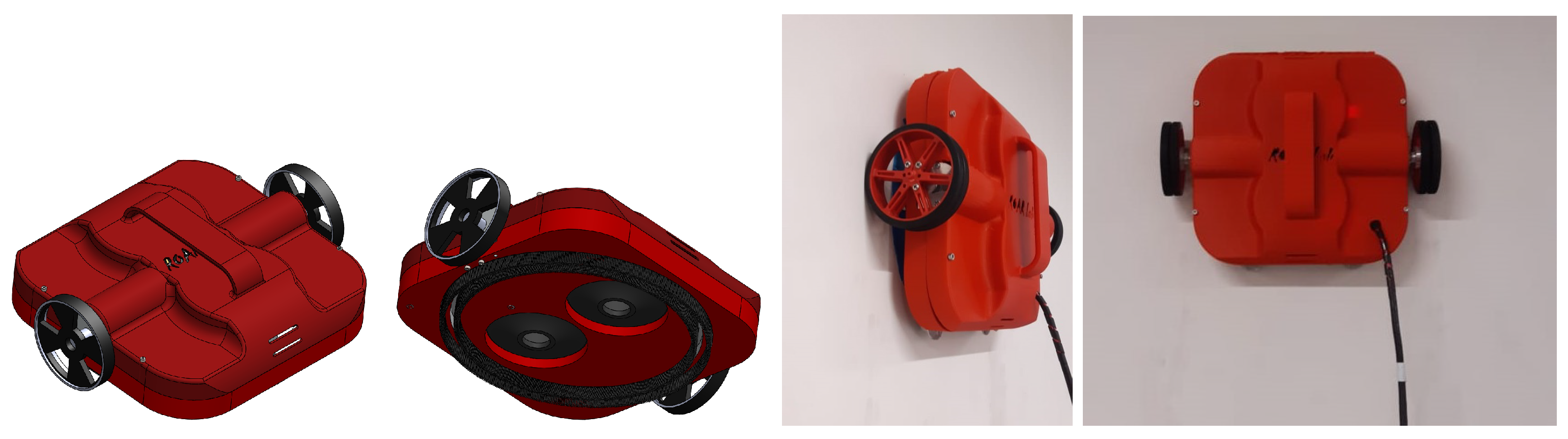
Wall-C is a differential drive robot developed for wall cleaning, with vacuum-based adhesion. The robot was developed to work in the presence of water and cleaning fluids. The design of Wall-C, along with the robot, is depicted in Figure 1. The robot can adhere to a wall and navigate on it without the support of additional infrastructure, which is one of the major benefits of a vacuum-based adhesion mechanism.
The part diagram of the robot is shown in Figure 2. The vacuum system generates friction between the cups (“CB1” and “CB2”) and the wall surface. Another system used to adhere to the robot is a pair of circular brushes (“CB1” and “CB2”) that separate the vacuum chamber from the environment. Moreover, the cups and the brush system together works as the sealing mechanism of the vacuum chamber. The robot dimensions are 235 × 230 × 70 mm. The cup and brush diameters are 200 mm (for “CB1”) and 180 mm (for “CB2”). The wheels (“DW”) are 75 mm diameter rubber wheels. To hang the robot, a handle (“H”) is on the top of the robot. To generate the suction, two brushless motor blowers (“BLW”) with a high-efficiency 8 kPa capacity are used. The system has been designed to remain adhered to the wall even with losses, since it is intended to operate on different sorts of walls, including surfaces with irregularities. To realize this, the power of the impeller motors is varied automatically to adapt the suction in the vacuum chamber; that is explained in Section 3. A pressure sensor is in the vacuum chamber to measure the pressure difference to take necessary control actions. It is assumed that one sensor is sufficient to measure the pressure, since the pressure is homogeneously distributed within the chamber.
Cleaning is carried out utilizing brushes on the bottom of the robot in contact with the wall. In the same way, these prevent water from coming directly into contact with the turbines through which air with a high degree of humidity passes but without the ability to wet the robot’s inner little circles. Wall-C does not load with a water tank, since that would increase the weight of the robot and make it difficult to adhere so that for cleaning with water the robot receives a manually applied external supply of water or cleaning agent.
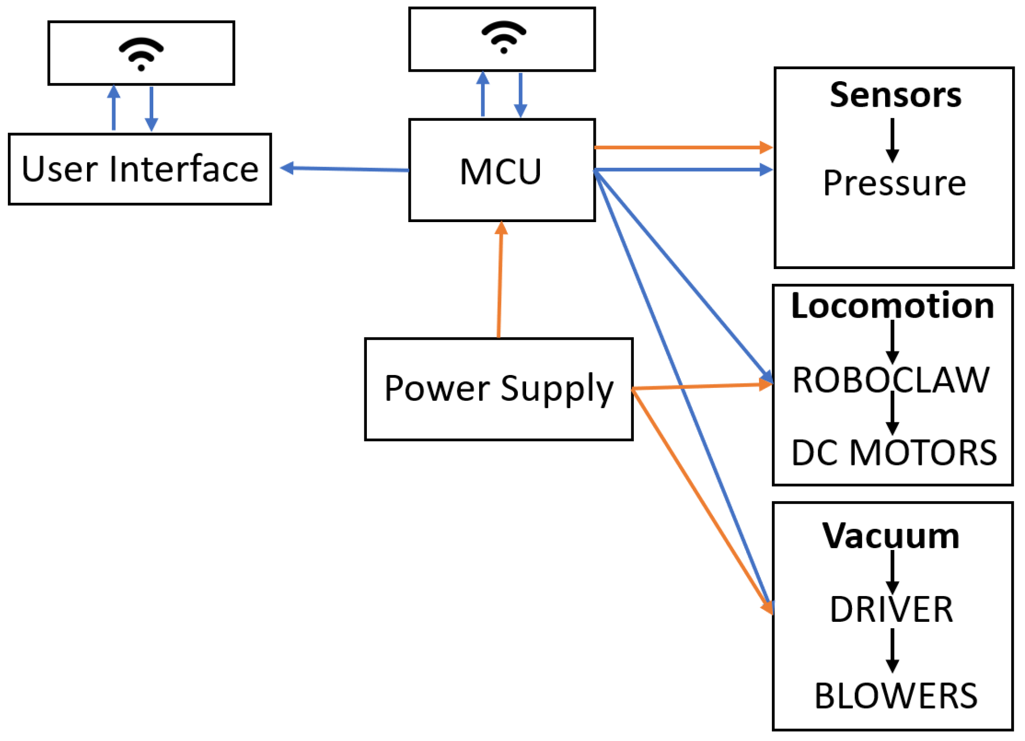
The hardware communication diagram is given in Figure 3. The blowers (“BLW”) are directly connected to their respective motor drivers (“BD_1” and “BD_2”), which in turn are controlled by a PWM from the microcontroller Unit (MCU). The locomotion of the robot is of differential type, having two DC motors (“DM”) placed on the x-axis of the robot equidistantly from the centroid of the robot and inertial system. A Roboclaw motor drive system is used to control the speed of the DC motors (“DM_L" and "DM_R”). A Roboclaw motor driver is capable of controlling up to two motors at the same time. The MCU sends the PWM to the motor driver to control the DC motor.
The electronic connections are described in Figure 4. The red and black lines represent the power supply for each device. Roboclaw and blower drivers receive 24 V to operate the DC motors and blowers. The pressure sensor and the wireless device work with a 5 V supply. The required electrical power is supplied from an external power source connected to the robot through an umbilical cord.
The robot is controlled by an application which is used in mobile phones and/or tablets. A virtual Joystick in the mobile application acts as a two-dimensional controller. The application maps the values delivered by the Joystick and assigns a range of 0–1. These values of 0–1 are multiplied by the maximum safe speed empirically estimated for robot navigation, which is 0.5 rev/s (12.5 cm/s). The navigational speed that does not affect the stability of the robot’s grip on the wall is considered a safe speed. When starting at high speeds, the robot may lose adhesion to the wall.
3. Improving Safety and Reliability Based on Adhesion-Awareness
3.1. Rationale behind Controlling Adhesion
A situation in which a robot is statically attached to a wall surface, as shown in Figure 5, is used here to explain the force distribution of a robot with vacuum-based adhesion. The adhesion force is acting toward the wall due to the pressure difference between atmosphere pressure () and the pressure of the inside chamber (). The pressure of the inside chamber is assumed to be homogeneously distributed across the chamber. This pressure difference was built due to the work done by the impeller mechanism attached to the robot. The adhesion force acting on the robot toward the wall, , can be obtained from (1), where A is the area of the vacuum chamber.
As a result of this adhesion force, the orthogonal reaction force acts on the robot (). The summation of friction forces acting on the robot, , can be obtained from (2), where is the equivalent coefficient of friction between the wall surface and the robot. The wall surface and different parts of the robot, which are in contact with the wall, such as circular brushes and cups, generate the friction forces between them. The equivalent frictional coefficient, , depends on the condition of the wall surface and the robot’s parts that are in contact with the wall.
The robot needs to stay attached to the wall for its operation. Moreover, it should not fall offs downward due to the weight of the robot. Therefore, the critical condition for falling off can be defined as by considering the forces in the vertical direction, where m and g are mass of the robot and the acceleration of gravity respectively. This yields the condition given in (3).
Since the center of gravity of the robot is positioned with a horizontal displacement of from the wall surface, there is a possible danger of overturning the robot, which hinders the attachment to the wall surface. The critical condition for avoiding the possibility of overturning can be defined as by taking moments around the bottom contact point, “O”. The robot height is considered .
To avoid the fall off and overturn, the vacuum system should provide a suction power that satisfies the condition (5). Moreover, the suction power should be more than enough to provide the necessary pressure difference.
A higher adhesion force ensures the safety of the robot, since it avoids the falling off and overturning. On the other hand, the equivalent normal force acting on the robot (i.e., ) increases with the increase of adhesion force. Subsequently, it yields higher frictional forces on the robot. As a result of this phenomenon, the torque required by the drive motors to achieve locomotion increases to a level that might stall the drive motors. Thus, too much adhesion force brings consequences to the locomotion of the robot. Based on these facts, it can be concluded that the pressure difference, P (defined as ) should be within a critical range to maintain the safety of the adhesion and consistency of locomotion.
The pressure difference, P, is difficult to keep steady by operating the vacuum impeller at a constant power, due to the external disturbances. The attached wall surface might have irregularities that create varying air leakages in the sealing mechanism. In addition to that, there can be unexpected air leakages due to the degradation of the sealing mechanism of the robot. According to [29], the pressure difference built by the impeller mechanism decreases with the airflow due to leakages if the work done by the vacuum impeller is constant. On the other hand, the pressure difference might be too high in cases where the robot is operated on a very smooth wall surface (due to very low air leakage). Thus, the power of the impeller mechanism should be controlled to maintain the required suction force that enables the safe and reliable operation of the robot. These sorts of disturbances caused to the adhesion mechanism cannot be easily observed by a human operator. Furthermore, corrective measures cannot be taken by a human operator due to time constraints. The loss of adequate pressure to provide adhesion would lead to overturning or falling off the robot from a wall surface. This is a crucial safety issue of a wall cleaning robot. Hence, a wall cleaning robot should be capable of autonomously adapting its vacuum impeller power to maintain the pressure difference within a desirable range for improving the operational safety and reliability of the robot. Moreover, a wall cleaning robot should be aware of the adhesion status; subsequently, it should take safety measures based on the adhesion-awareness.
3.2. An Adhesion-Awareness Based Control Strategy to Improve Safety and Reliability
Fuzzy logic is an intelligent approach that can successfully cope with any discretionary complex behavior [32]. It has the ability to model behavior or process without knowing the accurate underlying dynamics [33,34], and allows transformations of conditional statements that can be linguistically expressed to a nonlinear mapping [32,33]. Furthermore, fuzzy logic can effectively deal with uncertainties in data due to sensor noise [33,34]. Therefore, the proposed control strategy based on adhesion-awareness to enhance safety and reliability was developed using a fuzzy inference system. The configuration of the proposed fuzzy inference system is depicted in Figure 6. The proposed fuzzy inference system takes pressure difference (P) and present impeller power (C) as the inputs. The two inputs are fuzzified by the fuzzification layer with the aid of input membership functions defined for the two inputs. Moreover, input data are converted into linguistic values that can be explained from fuzzy sets. The input membership functions are given in Figure 7a,b for P and C respectively. The corresponding fuzzified inputs are defined as and .
A set of linguistic rues that characterizes the control goals and policy of the system are included in the knowledge base. The set of rules are defined based on expert knowledge. The rule base of the proposed fuzzy inference system is given in Table 1. The decision making logic of the fuzzy inference system considers this rule base to infer fuzzy control actions. Moreover, it maps the input space and output space based on the set of linguistic rules defined in the rule base. The fuzzy intersection operator (i.e., minimum) and fuzzy union operator (i.e., maximum) are used as t-norm and t-conorm operators respectively [35]. Thus, the firing strength of the rule, is computed as in (6).
ith rule leads to the control decision given in (7) based on Mamdani’s minimum operation rule [35]. Moreover, the corresponding fuzzy consequents are clipped by the respective firing strength of a rule. Consequently, the membership function of the inferred fuzzy results is given by (8), where n is the number of rules, since the fuzzy union operator is used for the aggregation.
To obtain a deterministic action to control the suction power of the vacuum impeller, the aggregated membership function of the fuzzy outputs is defuzzified in the defuzzification layer. Moreover, a crisp output, which represents the required impeller power, is obtained in defuzzification. The center of area method [35] is used for defuzzification. Thus, the defuzzified output, () can be obtained from (9).
The duty ratio of the impeller motors is adjusted in accordance with to control the suction power to the required level. Overall, the fuzzy inference system is designed in such a way that it regulates the pressure difference within a particular range based on the adhesion-awareness to ensure the safety and reliability of the robot, and the efficiency. The system establishes the adhesion-awareness by inferring the adhesion force based on the pressure difference. The decision surface of the fuzzy inference system is shown in Figure 8 where it visualizes the expected variation of the required impeller power (R) with the two inputs—pressure difference (P) and present impeller power (C). The maximum value of is bounded to 97.5 since the center of the area method is used for defuzzification. To get the full use of impeller power, the duty ratio (i.e., ) of the impeller is obtained by calibrating the mapping between the duty ratio and required impeller power (R) as .
4. Results and Discussion
4.1. Experimental Setup
The proposed control strategy to improve the safety and reliability of a wall cleaning robot based on adhesion-awareness has been incorporated into the developed Wall-C robot. The thresholds of pressure difference that should be maintained in the robot were determined experimentally by observing the robot behavior with different parameter settings. It was found that the pressure difference (P) should be maintained in the range 3.1–3.7 kPa for better performance. Therefore, the fuzzy inference system has been designed to regulate P within this region with more biased toward the upper side by considering the safety concerns. This decision was made since the robot can perform locomotion without any difficulties until kPa. The robot faces difficulties in performing locomotion when kPa, and the locomotion ability fails due to excessive friction forces when kPa. In an event of kPa, the robot will fall off, yielding a safety breach. Thus, KPa is considered a risk of falling in the design of the fuzzy inference system. The ranges of input and output membership functions of the fuzzy inference system have been defined based on these observations.
To validate the performance of the proposed control strategy based on adhesion-awareness, the behavior of Wall-C with adhesion-awareness was compared against Wall-C with no adhesion-awareness. The behaviors of the two systems were compared to each other in different test scenarios shows in Figure 9. In each scenario, the robot was teleoperated to move 1 m in the horizontal direction, as annotated as . The cases of the robot with adhesion-awareness and robot with no adhesion-awareness were considered for the test scenarios. The other conditions of the robot, such as supply voltage, were kept the same for the robot with adhesion-awareness and robot with no adhesion-awareness cases. The variation of the internal parameters of the robot, such as P and R, were recorded in each run. In addition to that, a stationary camera was placed in front of the vertical surface to capture the movement of the robot in each run. The trajectories of the robot were traced from the captured videos using Kinovea (www.kinovea.org) software for the analysis of behavior. A marker was placed on top of the robot for the tracking process. The trajectories traced from the external camera were taken as the ground truth. In the case of the robot with no adhesion-awareness, the required impeller power (R) was set to 80% to have P just below 4.2 kPa considering a safety margin and operational behavior. It should be noted that the wall surfaces of all the scenarios were perfectly vertical without having an inclination.
4.2. Experiment and Results
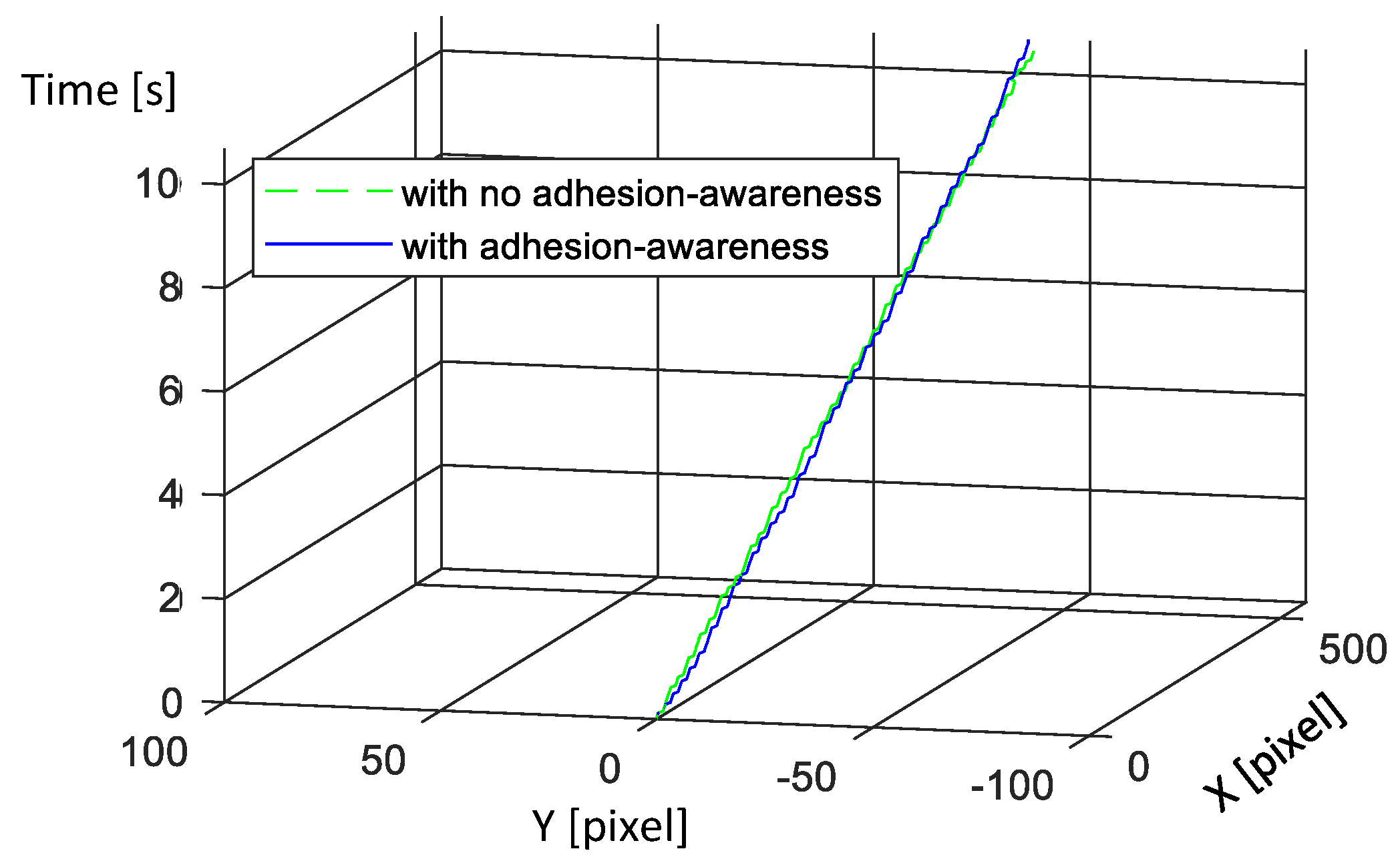
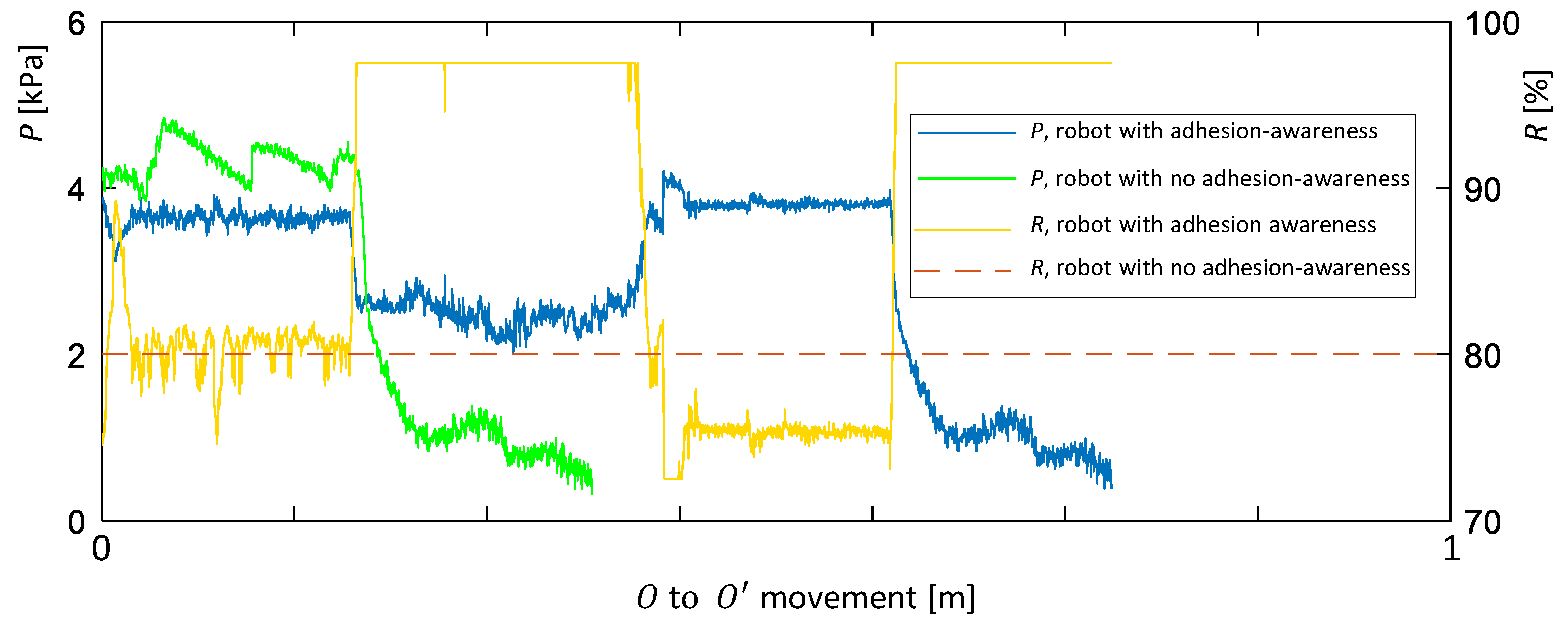
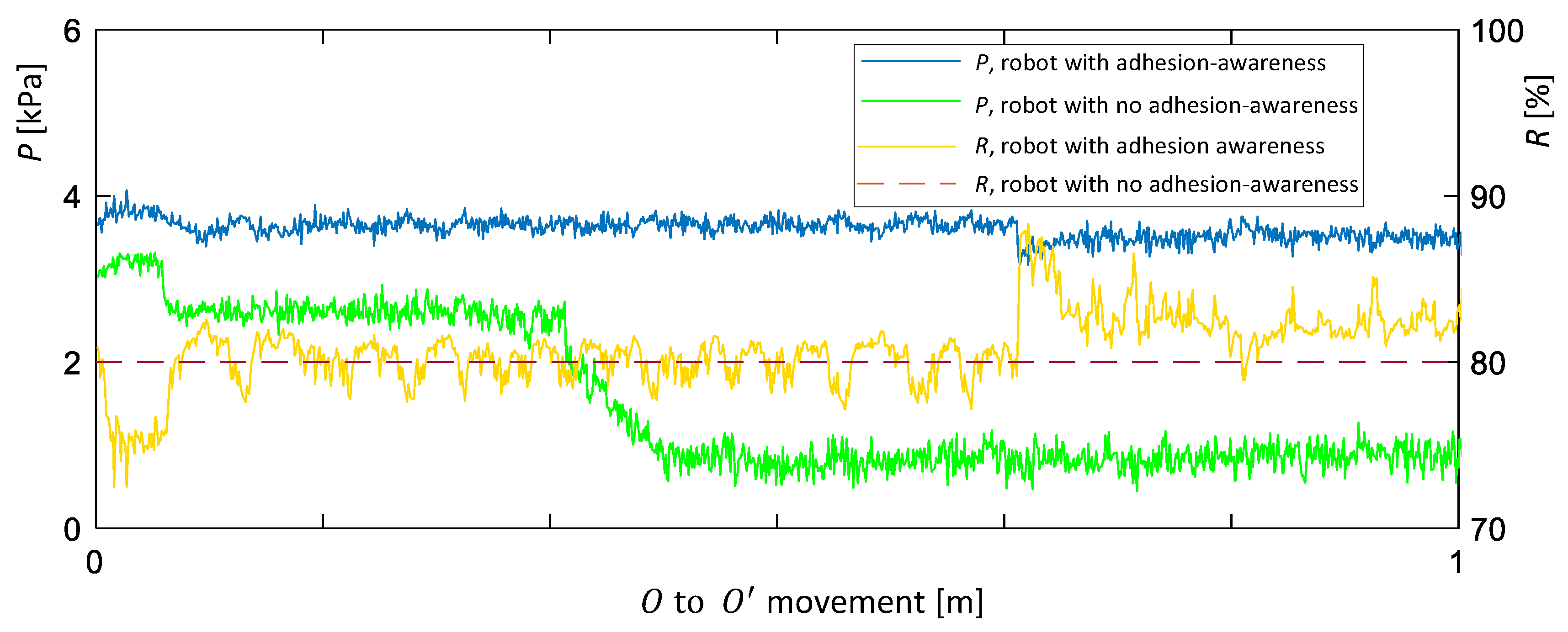
In the first scenario, the robot was operated in a typical indoor cement wall. The robot was initially placed at O and then moved toward , which is 1 m away from the initial position in the horizontal direction, through teleoperation. The same was done to the robot with the proposed control strategy based on adhesion-awareness and the robot with no adhesion-awareness. The variations of the internal parameters of the robot in this scenario for both cases are shown in Figure 10. In the case of the robot with no adhesion-awareness, pressure difference, P had a slight variation around 4.1 kPa (mean, M = 4.12 kPa, standard deviation, SD = 0.04, minimum = 3.97 kPa, maximum = 4.25 kPa), and impeller power, R, was kept fixed at 80%. In the case of the robot with adhesion-awareness, P had a slight variation of around 3.7 kPa (M = 3.76 kPa, SD = 0.04, minimum = 3.56 kPa, maximum = 4.11 kPa). However, the impeller power, R, was not fixed, and it varied to regulate the pressure difference, P. Most of the time, R was close to 75% and it occasionally rose to just above 80%. The mean value of the impeller power (R) in this case was 76.1% (SD = 1.11). In both cases, the robot was able to provide a suitable level of pressure difference to maintain the adhesion while without hindering the locomotion due to excessive adhesion force. The trajectories of the robot traced from the external camera shown in Figure 11 also confirm this. No sudden deviation of the robot’s position along the vertical axis indicates that there was no falling off situation. In addition to that, the linearity and continuity of the position variation with time along the horizontal axis suggest that the robot navigated without any issue. The trajectories of the robot during the two runs (with adhesion-awareness and with no adhesion-awareness) almost coincide. Therefore, adhesion performances of the robot with adhesion-awareness and the robot with no adhesion-awareness were almost the same. From the perspective of efficiency, the average impeller power of the robot with adhesion-awareness is less than that of the robot with no adhesion-awareness by 3.9% in this scenario.
In the second scenario, the robot was placed on a vertical surface which had two vertical negative dents, as shown in Figure 9b, to evaluate the behavior of the two configurations of the robot (i.e, with adhesion-awareness and with no adhesion-awareness). This wall had a more polished surface compared to the indoor cement wall used in the first scenario. The first dent was a rectangular shape with a width of 3 mm and a depth of 10 mm. The second dent had the same width as the first dent. However, that dent did not have a bottom. In other words, it was a fully open gap. As in the previous scenario, the robot was teleoperated toward from its initial position O, and the parameters were recorded for both configurations of the robot. The variations of the important parameters of the robot in this scenario are given in Figure 12. The corresponding trajectories of the robot traced by the external camera are plotted in Figure 13. In the robot with no adhesion-awareness case, initially, the robot maintained a marginally higher-pressure difference (P) than the desired one. The mean value of P was 4.3 kPa (SD = 0. 21) with a peak of 4.80 kPa, which causes difficulties for the locomotion due to excessive adhesion. As a result of this, P had a higher variation due to the non-smooth movement of the sealing mechanism with the locomotion. Despite that, the robot was able to attach to the surface without hindering the safety. Nevertheless, when the robot reached the first dent, P steeply fell, causing the robot to lose the adhesion and ultimately fall off. The falling off event could also be observed from the trajectory plot. In that event, a sudden variation in the robot’s position in the negative direction of the vertical axis can be noticed. This exhibits that the robot with no adhesion-awareness is not capable of maintaining reliability and safety of operation due to lack of ability in adapting the vacuum power. On the other hand, the robot with adhesion-awareness maintained P within the desired range in the initial segment, due to its ability of adapting vacuum power (M = 3.62 kPa, SD = 0.11, maximum = 3.91 kPa, minimum = 3.12 kPa). P started to drop when the robot reached the first dent. However, the fuzzy inference system took measures to increase the vacuum power to compensate for the pressure drop due to the air leakage. At this point, the required impeller power, R rose to 97.5%, which is the maximum point of operation for the vacuum system. The mean of P during the robot passing through the dent was 2.54 kPa; the minimum value was 2.02 kPa (for a short time). According to the traced trajectories of the robot (shown in Figure 13), there was no sudden variation in the robot’s position along the negative direction of the vertical axis. Thus, it can be concluded that the robot was able to move through the first negative dent without falling off. After the robot passed the first dent, the pressure rose to back to the desired range with slight deviations. In the event of the robot reaching the second dent, P started to drop steeply. As with to the first dent, the fuzzy inference system took measures to raise the vacuum power to the maximum to mitigate the pressure drop. Nevertheless, the maximum vacuum power was also not enough to maintain the pressure, due to the heavy airflow through the open gap; the robot fell off. This falling off event can be identified from the robot’s trajectory as an unexpected variation of the position along the negative direction of the vertical axis. This suggests that the amount of compensation provided by increasing the vacuum power is limited, and the system is not capable of handling fully open dents. The existence of such a fully open dent in the middle of a wall is rare, and an edge of a wall can be considered as an equivalent scenario. However, an edge of a wall can be easily identified by an operator, or proximity sensors should be placed on the robot to identify an edge to clear up this limitation. Overall, it can be concluded that the robot with adhesion-awareness outperformed the robot with no adhesion-awareness in this scenario, with limitations. An explanatory video that shows the behavior of the Wall-C with adhesion-awareness and with no adhesion-awareness during the first and the second experimental scenarios is provided as Supplementary Materials.
In the third scenario, the robot was operated on a metal wall with an uneven curvature in the horizontal axis, as shown in Figure 9c. As in to the first two scenarios, the robot attempted to move from O to . The variations of the internal parameters of the robot for both cases (i.e., with adhesion-awareness and with no adhesion-awareness) are given in Figure 14. The trajectories of the robot traced from the external camera are given in Figure 15. In the initial segment, the robot with no adhesion-awareness maintained P around 3.2 kPa. The reason for this lower pressure difference (i.e., P) was the air leakage due to the curvature of the wall’s surface. When the robot was moved further, the pressure difference dropped below 3.0 kPa, increasing the risk of falling off. However, there were no falls in this segment, since the adhesion force was higher than the critical threshold for falling off. When the robot was moved further, there was a sudden drop of pressure difference, P below 1.8 kPa, which is the threshold of falling off. Thus, this event triggered a fall for the robot. This falling off can be observed from the trajectory plot shown in Figure 15. The sealing of the vacuum mechanism of the robot was unpredictably varied when the robot moved across the surface, due to the uneven curvature of the surface. Thereby, the air leakages are unexpectedly altered causing sudden variations to the pressure difference in this case (i.e., the robot with no adhesion-awareness). In contrast, the robot with adhesion-awareness could sustain the pressure difference within the preferred range by adapting the suction power based on the adhesion-awareness. Hence, falling off events could not be observed. The trajectory plot also confirms that there were no falling off events. Moreover, the adhesion-awareness facilitates the ability to take remedial actions to compensate for the pressure variation due to unexpected variation of air leakages caused by the uneven curvature of the wall surface. Therefore, the robot with adhesion-awareness surpassed the robot with no adhesion-awareness in terms of safety and reliability in the third scenario.
Occasions where the pressure difference is too high hinder the locomotion due to the excessive amount of friction forces that must be overcome by the drive motors. Conversely, a low-pressure difference causes a higher risk of falling off, which endangers a robot’s safety. If the vacuum is not adapted accordingly, the pressure difference will either rise or fall below the desired level during the operation of a robot on surfaces with different characteristics. Thereby, the ability of a wall cleaning robot to adapt the vacuum power based on adhesion-awareness is a crucial factor for improving the safety and reliability of operation.
The behavior of the robot in the test scenarios discussed above confirms that the proposed fuzzy inference systems can adapt the required vacuum power based on the adhesion-awareness. The amount of adhesion is inferred by measuring the pressure difference between the atmosphere and the vacuum chamber. When the pressure difference drops, the fuzzy inference systems takes necessary actions to adapt the vacuum power to countermeasure the pressure drop due to leakages in situations, such as negative dents. On occasions where the pressure difference rises than desired in situations such as polished walls, the power of the vacuum is deceased by the fuzzy inference system to counter the effect. Moreover, the adhesion-awareness is used to adapt the vacuum power to maintain the pressure within the desired range to improve safety and reliability. It also contributes to improving the efficiency of the robot. However, that has not been thoroughly investigated in the scope of this paper.
The three experimental scenarios selected for the validation exposed the robot to many heterogeneous events. For example, in the second scenario, the robot was exposed to a surface with different textures and two different negative dents. In addition to that, the experimental scenarios selected can be used to clearly explain and properly validate the proposed concept. The rationale behind selecting a horizontal movement for the robot instead of a vertical movement was that the horizontal movement is the one that is highly affected by falling off events. Furthermore, a horizontal movement without a velocity component in the vertical axis facilitates clearer identification of falling off events. For example, if the robot was to be moving vertically (up), the falling off situations could not be properly observed, since they would be hidden from the vertical component of velocity. The experimental outcomes would not be severely altered with the variation of the robot’s initial position and the goal position for the horizontal movement. Therefore, the initial and the goal position of the robot was kept 1 m apart in the horizontal axis in all the test cases to maintain the homogeneity.
Even when the vacuum system is operated at its maximum level, a robot cannot sustain the required pressure to ensure the adhesion in a situation where there is excessive air leakage (e.g., a situation similar to the second dent of the second scenario). In such cases, a robot with the proposed adhesion-awareness might fail in upholding the adhesion and ultimately compromise safety. Moreover, the capabilities of the proposed method for improving safety will rely on hardware limitations. Therefore, the usage of additional sensors to detect fully open situations, such as an edge of a wall, is proposed as a future design suggestion. In addition to that, segregation of the inside pressure chamber of the robot to different segments would also be useful in coping with such situations. Therefore, the investigation of such methods is proposed for future work.
5. Conclusions
This paper proposed a novel method with which to adapt the vacuum power of a wall cleaning robot based on adhesion-awareness. Air leakage of a wall cleaning robot can unexpectedly vary with the surface characteristics of the operating wall. As a result of this, the pressure difference will be deviated from the preferred range for safe and reliable operation, if the vacuum suction power is kept constant. Low adhesion force increases the risk of a robot’s safety due to falling off or overturning. On the other hand, too high of an adhesion force increases the risk of stalling the driving mechanism of a robot due to excessive frictional forces. Therefore, the ability of a wall cleaning robot for adapting the vacuum power to sustain the pressure difference within a preferred range is crucial for improving the safety and reliability of a wall cleaning robot.
The proposed control strategy was developed using a fuzzy inference system. The fuzzy inference system establishes the adhesion-awareness by analyzing the current pressure difference and the present power setting of the vacuum system. The current pressure difference can be measured from a pressure sensor placed in the vacuum chamber of a wall cleaning robot. The required vacuum power to sustain the adhesion force for safe and reliable operation is determined by the fuzzy inference system based on the established adhesion-awareness. Moreover, a fuzzy inference system was designed to attain the control goals for improving the safety and reliability of the adhesion of a wall cleaning robot. A novel wall cleaning robot named Wall-C has been designed and developed, incorporating the proposed control strategy based on adhesion-awareness.
To validate the performance and behavior of the proposed concept, a Wall-C robot with adhesion-awareness has been compared against the same robot with no adhesion-awareness (i.e., Wall-C with disabled adhesion-awareness). According to the experimental results, a wall cleaning robot with no adhesion-awareness faces difficulty in sustaining the pressure difference within the preferred range for safe and reliable operation in events where unexpected variations of air leakage can be observed due to surface characteristics. Moreover, a wall cleaning robot with no adhesion-awareness could not properly operate on walls with heterogeneous surface characteristics without hampering safety and reliability. In contrast, a wall cleaning robot with adhesion-awareness can adapt its suction power to sustain the pressure difference within a preferred range for safe and reliable operation. Moreover, the adhesion-awareness facilitates the ability of a robot to take on persuasive measures to sustain the pressure difference in events of unexpected variations of air leakages. Therefore, it can be concluded that the incorporation of the proposed control strategy based on adhesion-awareness improves the safety and reliability of a wall cleaning robot. However, the ability to cope with safety issues due to air leakages is limited due to hardware capabilities. The addition of extra sensors or hardware design modification would be helpful in mitigating such safety concerns. These hardware modifications are suggested as future design ideas.
The proposed control criterion assumes that the walls are perfectly vertical. Nevertheless, a wall cleaning robot might need to work on an inclined wall, and the pressure difference required for safe operation in such situations varies with the inclination angle. Machine learning methods such as reinforcement learning could be incorporated to autonomously determine a system’s parameters without knowing the exact dynamics [36]. Therefore, such machine learning methods could be used to determine the pressure difference required to compensate for the gravity in walls with different inclination angles. The incorporation of a method to determine the required pressure level based on the inclination of the surface is proposed for future work.
Supplementary Materials
A supplementary video is available online at https://www.mdpi.com/2073-8994/12/1/122/s1.
Author Contributions
Conceptualization, M.A.V.J.M., M.V.-H., and R.E.M.; implementation, M.A.V.J.M., M.V.-H., and S.R.V.; validation, M.A.V.J.M., M.V.-H., and S.R.V.; formal analysis, M.A.V.J.M.; writing—original draft preparation, M.A.V.J.M. and M.V.-H.; writing—review and editing, M.A.V.J.M., M.V.-H., and R.E.M.; supervision, R.E.M.; project administration, R.E.M.; funding acquisition, R.E.M. All authors have read and agreed to the published version of the manuscript.
Funding
This work was supported by National Robotics R&D Programme Office, Singapore under grants RGAST1702 and RGAST1907.
Conflicts of Interest
The authors declare no conflict of interest. The funders had no role in the design of the study; in the collection, analyses, or interpretation of data; in the writing of the manuscript, or in the decision to publish the results.
References
- Aboulnaga, M.M. High-Rise Buildings in Context of Sustainability; Urban Metaphors of Greater Cairo, Egypt: A Case Study on Sustainability and Strategic Environmental Assessment. In Sustainable High Rise Buildings in Urban Zones; Springer: Cham, Switzerland, 2017; pp. 163–217. [Google Scholar]
- Ahlfeldt, G.M.; McMillen, D.P. Tall buildings and land values: Height and construction cost elasticities in Chicago, 1870–2010. Rev. Econ. Stat. 2018, 100, 861–875. [Google Scholar] [CrossRef]
- Wordsworth, P.; Lee, R. Lee’s Building Maintenance Management; Blackwell Science: London, UK, 2001. [Google Scholar]
- Tun, T.T.; Huang, L.; Mohan, R.E.; Matthew, S.G.H. Four-wheel steering and driving mechanism for a reconfigurable floor cleaning robot. Autom. Constr. 2019, 106, 102796. [Google Scholar] [CrossRef]
- Bai, J.; Lian, S.; Liu, Z.; Wang, K.; Liu, D. Deep learning based robot for automatically picking up garbage on the grass. IEEE Trans. Consum. Electron. 2018, 64, 382–389. [Google Scholar] [CrossRef] [Green Version]
- Abramson, S.; Levin, A.; Levin, S.; Gur, D. Window Cleaning Robot. US Patent 10,383,492, 20 August 2019. [Google Scholar]
- Ilyas, M.; Yuyao, S.; Mohan, R.E.; Devarassu, M.; Kalimuthu, M. Design of sTetro: A modular, reconfigurable, and autonomous staircase cleaning robot. J. Sens. 2018, 2018, 8190802. [Google Scholar] [CrossRef]
- Kim, J.; Mishra, A.K.; Limosani, R.; Scafuro, M.; Cauli, N.; Santos-Victor, J.; Mazzolai, B.; Cavallo, F. Control strategies for cleaning robots in domestic applications: A comprehensive review. Int. J. Adv. Robot. Syst. 2019, 16. [Google Scholar] [CrossRef] [Green Version]
- Hon, C.K.; Chan, A.P. Safety management in repair, maintenance, minor alteration, and addition works: Knowledge management perspective. J. Manag. Eng. 2013, 30, 04014026. [Google Scholar] [CrossRef] [Green Version]
- Cardini, E.; Sohn, E.C. Above and Beyond: Access Techniques for the Assessment of Buildings and Structures. In AEI 2013: Building Solutions for Architectural Engineering; American Society of Civil Engineers: Reston, VA, USA, 2013; pp. 306–320. [Google Scholar]
- Schmidt, D.; Berns, K. Climbing robots for maintenance and inspections of vertical structures—A survey of design aspects and technologies. Robot. Auton. Syst. 2013, 61, 1288–1305. [Google Scholar] [CrossRef]
- Nansai, S.; Elara, M.; Tun, T.; Veerajagadheswar, P.; Pathmakumar, T. A novel nested reconfigurable approach for a glass façade cleaning robot. Inventions 2017, 2, 18. [Google Scholar] [CrossRef] [Green Version]
- Sun, G.; Li, X.; Li, P.; Yue, L.; Yu, Z.; Zhou, Y.; Liu, Y.H. Adaptive Vision-Based Control for Rope-Climbing Robot Manipulator. In Proceedings of the 2019 IEEE/RSJ International Conference on Intelligent Robots and Systems (IROS), Macau, China, 4–8 November 2019; pp. 1454–1459. [Google Scholar]
- Seo, K.; Cho, S.; Kim, T.; Kim, H.S.; Kim, J. Design and stability analysis of a novel wall-climbing robotic platform (ROPE RIDE). Mech. Mach. Theory 2013, 70, 189–208. [Google Scholar] [CrossRef]
- Jiang, J.-G.; Zhang, Y.; Shu, Z. Implementation of glass-curtain-wall cleaning robot driven by double flexible rope. Ind. Robot Int. J. 2014, 41, 429–438. [Google Scholar] [CrossRef]
- Moon, S.M.; Hong, D.; Kim, S.W.; Park, S. Building wall maintenance robot based on built-in guide rail. In Proceedings of the 2012 IEEE International Conference on Industrial Technology, Athens, Greece, 19–21 March 2012; pp. 498–503. [Google Scholar]
- Lee, Y.S.; Kim, S.H.; Gil, M.S.; Lee, S.H.; Kang, M.S.; Jang, S.H.; Yu, B.H.; Ryu, B.G.; Hong, D.; Han, C.S. The study on the integrated control system for curtain wall building façade cleaning robot. Autom. Constr. 2018, 94, 39–46. [Google Scholar] [CrossRef]
- Zhang, H.; Zhang, J.; Zong, G.; Wang, W.; Liu, R. Sky cleaner 3: A real pneumatic climbing robot for glass-wall cleaning. IEEE Robot. Autom. Mag. 2006, 13, 32–41. [Google Scholar] [CrossRef]
- Tun, T.T.; Elara, M.R.; Kalimuthu, M.; Vengadesh, A. Glass facade cleaning robot with passive suction cups and self-locking trapezoidal lead screw drive. Autom. Constr. 2018, 96, 180–188. [Google Scholar] [CrossRef]
- Wang, W.; Wang, K.; Zong, G.H.; Li, D.Z. Principle and experiment of vibrating suction method for wall-climbing robot. Vacuum 2010, 85, 107–112. [Google Scholar] [CrossRef]
- Nansai, S.; Mohan, R.E. A survey of wall climbing robots: Recent advances and challenges. Robotics 2016, 5, 14. [Google Scholar] [CrossRef] [Green Version]
- Anand, T.; Kushwaha, S.K.; Roslin, S.E.; Nandhitha, N. Flux controlled BLDC motor for automated glass cleaning robot. In Proceedings of the 2017 Third International Conference on Science Technology Engineering & Management (ICONSTEM), Chennai, India, 23–24 March 2017; pp. 955–959. [Google Scholar]
- Wu, G.; Zhang, H.; Zhang, B.; Zhang, L. Research on Design of Glass Wall Cleaning Robot. In Proceedings of the 2018 5th International Conference on Information Science and Control Engineering (ICISCE), Zhengzhou, China, 20–22 July 2018; pp. 932–935. [Google Scholar]
- Lee, G.; Kim, H.; Seo, K.; Kim, J.; Kim, H.S. MultiTrack: A multi-linked track robot with suction adhesion for climbing and transition. Robot. Auton. Syst. 2015, 72, 207–216. [Google Scholar] [CrossRef]
- Vega-Heredia, M.; Mohan, R.E.; Wen, T.Y.; Siti’Aisyah, J.; Vengadesh, A.; Ghanta, S.; Vinu, S. Design and modelling of a modular window cleaning robot. Autom. Constr. 2019, 103, 268–278. [Google Scholar] [CrossRef]
- Miyake, T.; Ishihara, H.; Yoshimura, M. Basic studies on wet adhesion system for wall climbing robots. In Proceedings of the 2007 IEEE/RSJ International Conference on Intelligent Robots and Systems, San Diego, CA, USA, 29 October–2 November 2007; pp. 1920–1925. [Google Scholar]
- Brusell, A.; Andrikopoulos, G.; Nikolakopoulos, G. Novel considerations on the negative pressure adhesion of electric ducted fans: An experimental study. In Proceedings of the 2017 25th Mediterranean Conference on Control and Automation (MED), Valletta, Malta, 3–6 July 2017; pp. 1404–1409. [Google Scholar]
- Xu, D.; Gao, X.; Wu, X.; Fan, N.; Li, K.; Kikuchi, K. Suction ability analyses of a novel wall climbing robot. In Proceedings of the 2006 IEEE International Conference on Robotics and Biomimetics, Kunming, China, 17–20 December 2006; pp. 1506–1511. [Google Scholar]
- Li, J.; Gao, X.; Fan, N.; Li, K.; Jiang, Z. BIT Climber: A centrifugal impeller-based wall climbing robot. In Proceedings of the 2009 International Conference on Mechatronics and Automation, Changchun, China, 9–12 August 2009; pp. 4605–4609. [Google Scholar]
- Andrikopoulos, G.; Papadimitriou, A.; Brusell, A.; Nikolakopoulos, G. On Model-Based Adhesion Control of a Vortex Climbing Robot. In Proceedings of the 2019 IEEE/RSJ International Conference on Intelligent Robots and Systems (IROS), Macau, China, 4–8 November 2019; pp. 1460–1465. [Google Scholar]
- Muthugala, M.A.V.J.; Vega-Herdia, M.; Ayyalusami, V.; Sriharsha, G.; Elara, M.R. Design of an Adhesion-Aware Facade Cleaning Robot. In Proceedings of the 2019 IEEE/RSJ International Conference on Intelligent Robots and Systems (IROS), Macau, China, 4–8 November 2019; pp. 1441–1447. [Google Scholar]
- Zadeh, L.A. Is there a need for fuzzy logic? Inf. Sci. 2008, 178, 2751–2779. [Google Scholar] [CrossRef]
- De Silva, C.W. Intelligent Control: Fuzzy Logic Applications; CRC Press: Boca Raton, FL, USA, 2018. [Google Scholar]
- Ross, T.J. Fuzzy Logic with Engineering Applications; John Wiley & Sons: Hoboken, NJ, USA, 2005. [Google Scholar]
- Lee, C.C. Fuzzy logic in control systems: Fuzzy logic controller. II. IEEE Trans. Syst. Man Cybern. 1990, 20, 419–435. [Google Scholar] [CrossRef]
- Chen, C.; Modares, H.; Xie, K.; Lewis, F.L.; Wan, Y.; Xie, S. Reinforcement learning-based adaptive optimal exponential tracking control of linear systems with unknown dynamics. IEEE Trans. Autom. Control 2019, 64, 4423–4438. [Google Scholar] [CrossRef]
Figure 1.
Wall-C design.

Figure 2.
Wall-C parts diagram with a top view (left) and side view (right).

Figure 3.
Signal and power supply architecture of Wall-C. The orange arrows represent the power supply and the blue ones data communication.
Figure 3.
Signal and power supply architecture of Wall-C. The orange arrows represent the power supply and the blue ones data communication.

Figure 4.
Power and communication physical connections circuit diagram.

Figure 5.
Force distribution of a robot with vacuum based adhesion. The variables and symbols are defined as follows. : atmospheric pressure; : pressure of the inside chamber; : adhesion force acting on the robot toward the wall; : orthogonal reaction force acted on the robot; : summation of friction forces between the robot and the wall; : the robot’s height; m: mass; g: acceleration of gravity; and : horizontal displacement of center of gravity of the robot.

Figure 6.
Configuration of the proposed fuzzy logic controller.

Figure 7.
(a) Input membership function for the pressure difference, P. (b) Input membership function for the present impeller power, C. (c) Membership function for the output, required impeller power (i.e., R). The fuzzy labels are defined as VL: very low, L: low, M: medium, H: high, and VH: very high.

Figure 8.
Fuzzy decision surface: expected variation of the output with the two inputs; pressure difference and present impeller power.
Figure 8.
Fuzzy decision surface: expected variation of the output with the two inputs; pressure difference and present impeller power.

Figure 9.
Experimental setups: (a) A typical wall surface. (b) A wall surface with two vertical negative dents of different depths. Both dents had a width of 3 mm. However, the depth of the first dent was 10 mm, and the second dent did not have a bottom (i.e., an open gap). (c) A metal wall surface with an uneven curvature.

Figure 10.
Variation of pressure difference (P) and impeller power (R) when the robot moves from O to on the typical wall surface (situation shown in Figure 9a).
Figure 10.
Variation of pressure difference (P) and impeller power (R) when the robot moves from O to on the typical wall surface (situation shown in Figure 9a).

Figure 11.
Trajectory of the robot when it was moved toward on the typical wall (situation shown in Figure 9a). The initial position of the marker is considered as the origin of x-y coordinate system; x: horizontal axis and y: vertical axis. It should be noted that the x and y axes are given in pixels, and one pixel represents 1.8 mm.

Figure 12.
Variation of pressure difference (P) and impeller power (R) when the robot moved from O to on the wall’s surface with two vertical negative dents (situation shown in Figure 9b). The distance axis was extrapolated after falls by assuming the distance moved was proportional to time.
Figure 12.
Variation of pressure difference (P) and impeller power (R) when the robot moved from O to on the wall’s surface with two vertical negative dents (situation shown in Figure 9b). The distance axis was extrapolated after falls by assuming the distance moved was proportional to time.

Figure 13.
Trajectory of the robot when it was moved toward on the wall’s surface with two vertical negative dents (situation shown in Figure 9b). The initial position of the marker is considered the origin of x-y coordinate system; x: horizontal axis and y: vertical axis. It should be noted that the x and y axes are given in pixels, and one pixel represents 0.71 mm. The falling off situations are annotated in dashed circles.

Figure 14.
Variation of pressure difference (P) and impeller power (R) when the robot moves from O to on a metal wall’s surface with an uneven curvature (situation shown in Figure 9c).
Figure 14.
Variation of pressure difference (P) and impeller power (R) when the robot moves from O to on a metal wall’s surface with an uneven curvature (situation shown in Figure 9c).

Figure 15.
Trajectory of the robot when it was moved toward on the metal wall surface with an uneven curvature (situation shown in Figure 9c). The initial position of the marker was considered as the origin of the x-y coordinate system; x—horizontal axis, and y—vertical axis. It should be noted that the x and y axes are given in pixels, and one pixel represents 1.08 mm. The falling off situations are annotated in dashed circles.


Table 1.
Rule base of the fuzzy inference system.
| i | Rule |
|---|---|
| 1 | If (P is L) and (C is L) then (R is M) |
| 2 | If (P is L) and (C is M) then (R is H) |
| 3 | If (P is L) and (C is H) then (R is VH) |
| 4 | If (P is M) and (C is L) then (R is L) |
| 5 | If (P is M) and (C is M) then (R is M) |
| 6 | If (P is M) and (C is H) then (R is H) |
| 7 | If (P is H) and (C is L) then (R is VL) |
| 8 | If (P is H) and (C is M) then (R is L) |
| 9 | If (P is H) and (C is H) then (R is M) |
© 2020 by the authors. Licensee MDPI, Basel, Switzerland. This article is an open access article distributed under the terms and conditions of the Creative Commons Attribution (CC BY) license (http://creativecommons.org/licenses/by/4.0/).
Share and Cite
MDPI and ACS Style
Muthugala, M.A.V.J.; Vega-Heredia, M.; Mohan, R.E.; Vishaal, S.R. Design and Control of a Wall Cleaning Robot with Adhesion-Awareness. Symmetry 2020, 12, 122. https://doi.org/10.3390/sym12010122
AMA Style
Muthugala MAVJ, Vega-Heredia M, Mohan RE, Vishaal SR. Design and Control of a Wall Cleaning Robot with Adhesion-Awareness. Symmetry. 2020; 12(1):122. https://doi.org/10.3390/sym12010122
Chicago/Turabian StyleMuthugala, M. A. Viraj J., Manuel Vega-Heredia, Rajesh Elara Mohan, and Suresh Raj Vishaal. 2020. "Design and Control of a Wall Cleaning Robot with Adhesion-Awareness" Symmetry 12, no. 1: 122. https://doi.org/10.3390/sym12010122
Note that from the first issue of 2016, this journal uses article numbers instead of page numbers. See further details here.