Chemical Clogging and Evolution of Head Losses in Steel Slag Filters Used for Phosphorus Removal


Department of Civil, Geological and Mining Engineering, Polytechnique Montreal, Montreal, QC H3C 3A7, Canada
*
Author to whom correspondence should be addressed.
Water 2020, 12(6), 1517; https://doi.org/10.3390/w12061517
Submission received: 21 April 2020
/
Revised: 13 May 2020
/
Accepted: 20 May 2020
/
Published: 26 May 2020
(This article belongs to the Special Issue Advances and Challenges in Improving Water Quality with Phosphorus Removal Structures: Scaling Up to the Field)
Abstract
:The objective of this study was to propose a conceptual model of clogging in alkaline granular filters. Two slag columns were operated for 600 days and monitored using piezometers and tracer tested at regular intervals. The type of influent (organic or inorganic) affected the loss of effective porosity in the filters. Well organized and loose crystal structures were observed by scanning electron microscopy in columns with inorganic and organic influents, respectively. It was postulated that the formation of crystals in unorganized structures results in confined voids that are not accessible for water flow, thus accelerating porosity loss. The effect of the combination of chemical clogging and biofilm on the porosity loss is higher than the effect of these two factors separately. The Kozeny-Carman equation for hydraulic conductivity could not efficiently predict the evolution of head losses in the column fed with an inorganic influent. The crystal structure and connectivity in the presence of homogeneous or heterogeneous precipitation are concepts that could improve predictions of hydraulic conductivity. The results of this study highlighted the importance of the inlet zone on the development of pressure head in alkaline granular filters. Future research on clogging should focus on precipitation mechanisms in the inlet zone and on the design of the feeding system.

1. Introduction
Alkaline granular filters (AGFs) are sand to gravel-size passive reactive filters efficient for phosphorus (P) removal from runoffs and wastewater. In AGFs, P removal occurs by precipitation of phosphate minerals associated with a pH rise (reaching as high as pH 13) induced by reactive media dissolution. Examples of AGF media include industrial by-products (fly ash, electric arc furnace slag, basic oxygen furnace slag, blast furnace slag), natural media (bauxite, calcite, seashells, apatite), or manmade media [1,2]. So far, the implementation of AGFs in full-scale applications has been limited by several challenges: phosphorus removal efficiency in the long term, uncertainty about longevity prediction, management of used media, neutralization of the alkaline effluent, costs of capitalization and maintenance, and clogging. This aim of this article is to fulfill the need for assessment and control of clogging in AGFs.
Clogging is the process of reduction in porosity and of modification in flow behavior in a granular media as a result of the accumulation of suspended solids, the formation of precipitates and the formation of biological material, eventually leading to hydraulic failure [3]. Such clogging problems have been reported in the literature on AGFs [4,5,6].
Three types of clogging occur in structures and reactors with flow in granular media: physical clogging (accumulation of suspended solids from influent), chemical clogging (precipitation reactions), and biological clogging (formation of biofilm and roots in the case of planted media) [7]. Chemical clogging is expected to be significant in AGFs due to the unavoidable precipitation of phosphate and carbonate mineral species, as shown by many mineralogical investigations [8,9,10,11,12]. The reduction of hydraulic efficiency by development of short-circuiting [6] or appearance of dead zones [13] has been shown in full-scale AGFs. Despite the importance of clogging on process performance and lifetime of AGFs, little effort has been dedicated to clogging mitigation. Most research on AGFs is focused on phosphorus removal capacity [1,14,15]. Several AGF designs proposed in the literature are promising for clogging control, such as using coarse media in prefilters [16] or in layers close to inlet piping [17], sealing media containers to minimize atmospheric CO2 input [8], reducing inorganic carbon input by recirculation [18] or reactivating the filter by dig-repack-rest [17], but these designs were not optimized regarding clogging mitigation. Moreover, literature on the hydraulic conductivity of AGFs is sparse. The clean media hydraulic conductivity is sometimes reported [11,12,19]. Measurements of hydraulic conductivity at regular intervals on columns have been conducted [20], and the increase of water head needed to induce flow in a phosphorus removal structure has been monitored [6], but overall, in situ measurements of hydraulic conductivity and the description of its evolution over the period of operation are lacking. Additionally, equations for prediction of hydraulic conductivity that are used in other granular media applications with clogging [21,22] have not been tested yet in AGFs. There is a need for a better understanding of clogging mechanisms occurring in AGFs, especially chemical clogging. This knowledge is needed to help future efforts in clogging control and development of clogging mitigation strategies.
Objective
The objective of this project was to propose a conceptual model of clogging in AGFs. The specific objectives were to:
- (1)
- evaluate the long-term impacts of clogging on the loss of effective porosity,
- (2)
- describe clogging mechanisms, and
- (3)
- quantify clogging by monitoring the pressure head build up in steel slag filters fed with a synthetic influent.
To fulfill the objectives, two column experiments filled with slag were operated and characterized using tracer tests, pressure monitoring, and mineralogical investigations.
2. Materials and Methods
2.1. Slag Media
EAF slag measuring 5–10 mm was used in column experiments (supplied by Harsco Minerals, Contrecoeur, Canada). The slag properties were grain density of 3.8 g/cm3, specific surface of 0.308 m2/g, and chemical composition of 33% Fe2O3, 30% CaO, 16% SiO2, 12% MgO, 6% Al2O3, and 3% others, as determined in previous work [23].
2.2. Column Experiment
Two vertical columns (columns 1 and 2) were bottom fed with a synthetic influent using a peristaltic pump in saturated mode at about 25 °C. The influent of column 1 was composed of soluble inorganic salts, while that of column 2 contained soluble readily biodegradable organic matter (acetate) but without nutrient addition. The influent of column 1 reproduced a domestic wastewater effluent treated at tertiary level, while the influent of column 2 was designed for clogging study purposes. An acetate buffer was selected for column 2 in order to offer a buffer capacity similar to the influent of column 1, while offering organic matter. No nutrient was added to the rapidly biodegradable organic matter of influent of column 2 to avoid the rapid development of a biofilm that would rapidly lead to biofouling. Influent and effluent tubing had an internal diameter of 6 mm. The effluent tubing was kept saturated over a length of 50 cm to minimize CO2 input in the column.
The column main properties are provided in Table 1. Each column was divided into 11 virtual cells, identified as #0 (bottom) to #10 (top). Cells #1 to #9 were 15 cm long with a side sampling hole in the middle. Cells #0 and #10 were 7.5 cm long with no sampling holes to provide a transition zone between inlet/outlet areas and sampling areas. A maximum of three cells were sampled in the same day to minimize disturbance. The feeding barrels, column effluents, and cells were sampled periodically for pH, ortho-phosphates (o-PO4), filtered calcium, settled total inorganic carbon (TIC), settled total organic carbon (TOC), total phosphorus, alkalinity, and chemical oxygen demand (COD) using standard procedures [24]. Settled TIC measurements were preferred to dissolved inorganic carbon measurements to avoid an analytical artefact caused by the filtration protocol. Indeed, samples with high pH are carbon dioxide traps. Processing such samples in conventional Buchner filters results in carbon dioxide entrapment and increases the inorganic carbon concentration of the sample. TIC samples were left for settling half an hour in beakers sealed with parafilm before being poured in a 6 mL tube sealed with parafilm. Note that column 1 was described in a previous study [23].
The total porosity n and HRTV were calculated using Equations (1) and (2), respectively, with being the void volume at time 0 (mL), the total volume of the empty column (mL) and Q the influent flowrate. was calculated from the known mass of slag in each column: , with being the mass of slag (g).
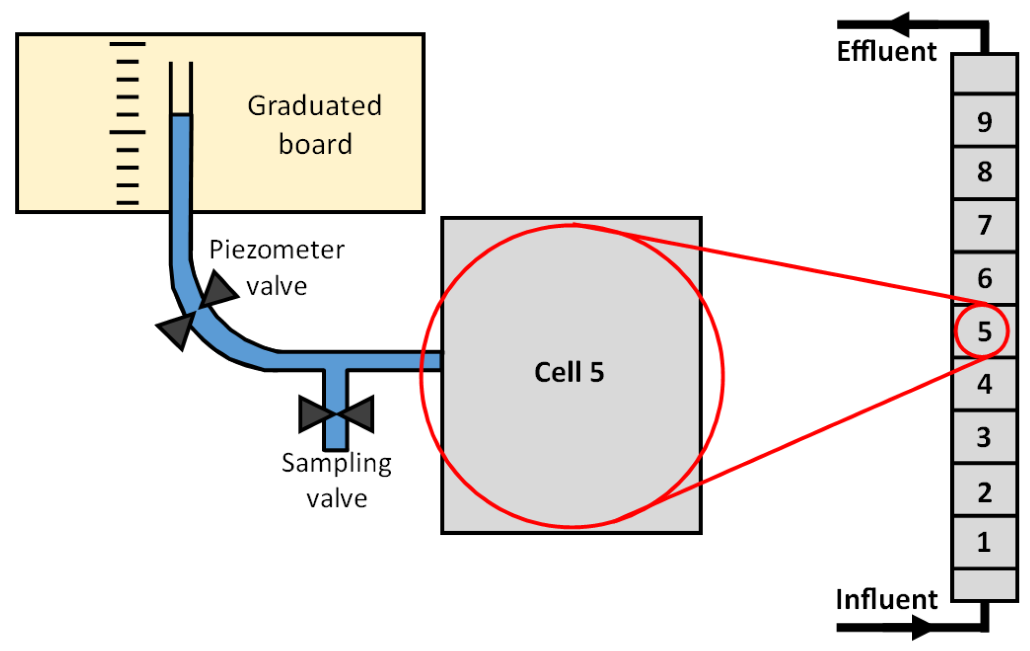
In column 1, the water level within cells #1 to #9 was measured with piezometers connected to sampling valves, as shown in Figure 1.
The piezometers and the sampling valves were continuously kept opened and closed, respectively. At each sampling campaign, all water levels were read first. Then, for each cell, the piezometer valve was closed, the sampling valve was slowly opened, and the first 30 mL was discarded before taking the sample. The head loss at cell j was defined according to Equation (3):
where is the head loss (cm H2O) within cell j, is the water level measured in cell j+1 (cm H2O), and is the water level measured in cell j (cm H2O). The initial hydraulic conductivity of column 2 was estimated at 0.1 m/s based on measurements performed one day before starting the experiment (procedure and experimental data of hydraulic conductivity presented in Table S1). Water levels in column 2 were not measured during the operation due to excessive clogging in sampling tubing and piezometers.
Pulse tracer tests were conducted periodically in columns 1 (days 12, 69, 82, 107, 187, 271, 376 and 558) and 2 (days 4, 249, 319, 389). Rhodamine was used as the tracer at an injection concentration of 20 mg/L. The rhodamine concentration was measured in the effluent using a spectrofluorometer (model Shimadzu RF-1501, excitation 530 nm, emission 555 nm). The effluent rhodamine concentration was monitored during one week. The sampling frequency was every 11 minutes during the peak phase (during the first 24 h) and up to every six hours during the tail phase (24 h after injection).
2.3. Characterization of Used Slag Media
At the end of operation, columns were left saturated for six days (column 1) and 10 days (column 2) before dismantling. A few minutes before the dismantling campaign, pore water was sampled and analyzed for pH in each cell. Columns were then cut in four sections to allow slag media sampling at different heights with minimal disturbance. First, undisturbed slag particles were carefully sampled in all cells and left to dry at room temperature. Selected undisturbed dried slag samples from the first cells (cells 1, 2, 3, 5, and 8 in column 1 and cells 2, 3, 4, 5, 6, and 9 in column 2) were characterized by scanning electron microscopy (SEM) using a Jeol JSM-7600 microscope (2.0 kV, LEI detector). Second, slag samples were washed with tap water in a large pan and precipitates were sampled after settling in the pan (Figure S1, Supplementary Materials). Precipitates were air-dried for three days, sieved at mesh 60 and cleaned from slag dust using a strong magnet. Precipitates from all cells were analyzed by X-ray diffraction (Philipps X’Pert diffractometer, 50 kV, 40 mA, Bragg-Brentano geometry, Cukα radiation). The mean calcite crystal size in precipitate samples was estimated with the Scherrer equation [25] using the ~29.4° calcite peak in diffractograms. A 300 g washed slag sample was taken from cells 1 and 2. The saturation pH of each washed slag sample was determined in a three-day batch test. Batch tests were performed to according to the procedure described by Claveau-Mallet et al. 2017 [23].
Briefly, the slag sample was contacted with 350 mL or 700 mL of a synthetic solution in a closed 1 L Erlenmeyer flask. The Erlenmeyer flask was rotated at 160 rpm. The solution was prepared using CaCl2, KH2PO4, and K2HPO4 in distilled water and its composition was pH = 6.75, TIC = 0.7 mg/L, calcium = 20 mg/L and o-PO4 = 9.8 mg P/L. The pH was monitored continuously in the closed flask until the saturation pH was reached (in the form of a pH plateau).
2.4. Characterization of Porosity Loss
The progressive reduction in total porosity n (defined as the fraction of volume occupied by voids filled with water or air in the reactor) and effective porosity ne (defined as porosity used for water flow) following precipitate accumulation was assessed by mass balance and tracer tests, respectively.
2.4.1. Evolution of Total Porosity
The loss of total porosity was calculated assuming that voids were progressively filled with hydroxyapatite (Ca5(PO4)3OH) and calcite (CaCO3). It was assumed that 100% of removed o-PO4 was transformed into hydroxyapatite (phosphorus representing 18.5% of hydroxyapatite mass) and 100% of removed TIC was transformed into calcite. Hydroxyapatite formation was assumed based on previous XRD measurements made in column 1 [23]. The atmospheric carbon dioxide input in columns was assumed to be negligible. The total porosity n at time t was calculated for each column cell according to Equations (4) and (5):
where is the void volume at time 0 (mL), is the volume occupied by crystals (mL), is the total cell volume (mL), and are o-PO4 concentrations in the influent and effluent (g P/L), and are TIC concentrations in the influent and effluent (g/L), and are the molecular weights of hydroxyapatite (502 g/mol) and calcite (100 g/mol), and are the molecular weight of phosphorus (31 g/mol) and carbon (12 g/mol), and are the crystal density of hydroxyapatite (3.6 g/mL) and calcite (2.7 g/mL) [26], and Q is the influent flowrate (L/d).
2.4.2. Evolution of Effective Porosity
The evolution of effective porosity was determined based on tracer test calibration. Each tracer test was simulated using the software PHREEQC and its double porosity model [27], using MATLAB-PHREEQC functions launch_tracertest.m and PHREEQCfct_tracer.m provided in Supplementary Materials. Briefly, the TRANSPORT module in PHREEQC simulates a 1D flow in a column. The column is divided into n numerical cells, each of which is completely mixed and hosts kinetic reactions defined by the user. Advection is simulated by the shift of solutions from one cell to the other. Dispersion is simulated by partial mixing of solutions in adjacent cells. The double porosity feature simulates retardation by adding n immobile cells adjacent to mobile cells. Solute exchange between mobile and immobile cells is computed by partial mixing and no advection is possible in immobile cells. The hydraulic parameters used in PHREEQC are the effective hydraulic retention time of voids (HRTVe, h), the dispersivity (D*, cm), and the exchange factor between mobile and immobile cells (Dn, s−1). Each tracer test was calibrated by heuristic optimization of the hydraulic parameters.
For comparison purpose, tracer tests were calibrated with the tank-in-series (TIS) model traditionally used in wastewater treatment modelling and employed in wetland modelling [7]. In this model, the migration of solute in the porous media is represented by a flow in a succession of completely stirred tank reactors.
This model can be represented by a gamma distribution (Equation (6)), in which N is the number of tanks and t is time. Note that N does not have to be an integer in this equation. As the gamma distribution is a probability density function, the tracer response curve is transformed into an f(t) function by normalization with the total tracer mass (Equation (7)). Calibration of the model using hydraulic parameters N and HRTVe was done by minimizing the error between Equations (6) and (7) [7].
2.5. Prediction of Pressure Head Buildup
The evolution of pressure head buildup in each cell of column 1 was predicted based on the Darcy’s law [28], where is the pressure head (m), Q the flow rate (m3/s), the flow path length (m), A the column area (m2) and the hydraulic conductivity at time t (m/s):
The evolution of the hydraulic conductivity of each cell between t = 0 and 625 d was estimated based on the Kozeny–Carman relationship [29]:
where is the initial hydraulic conductivity (0.1 m/s), n is the porosity as defined in Equation (4), is the initial porosity (0.492), S is the specific surface of the media (including slag and precipitates, m2/m3), and is the initial specific surface of the media (slag only, m2/m3). S and were calculated assuming single-sized spherical particles for both slag and precipitates.
3. Results and Discussion
Raw experimental data of the column tests is provided in Supplementary Materials.
3.1. Evolution of Water Composition in Column Tests
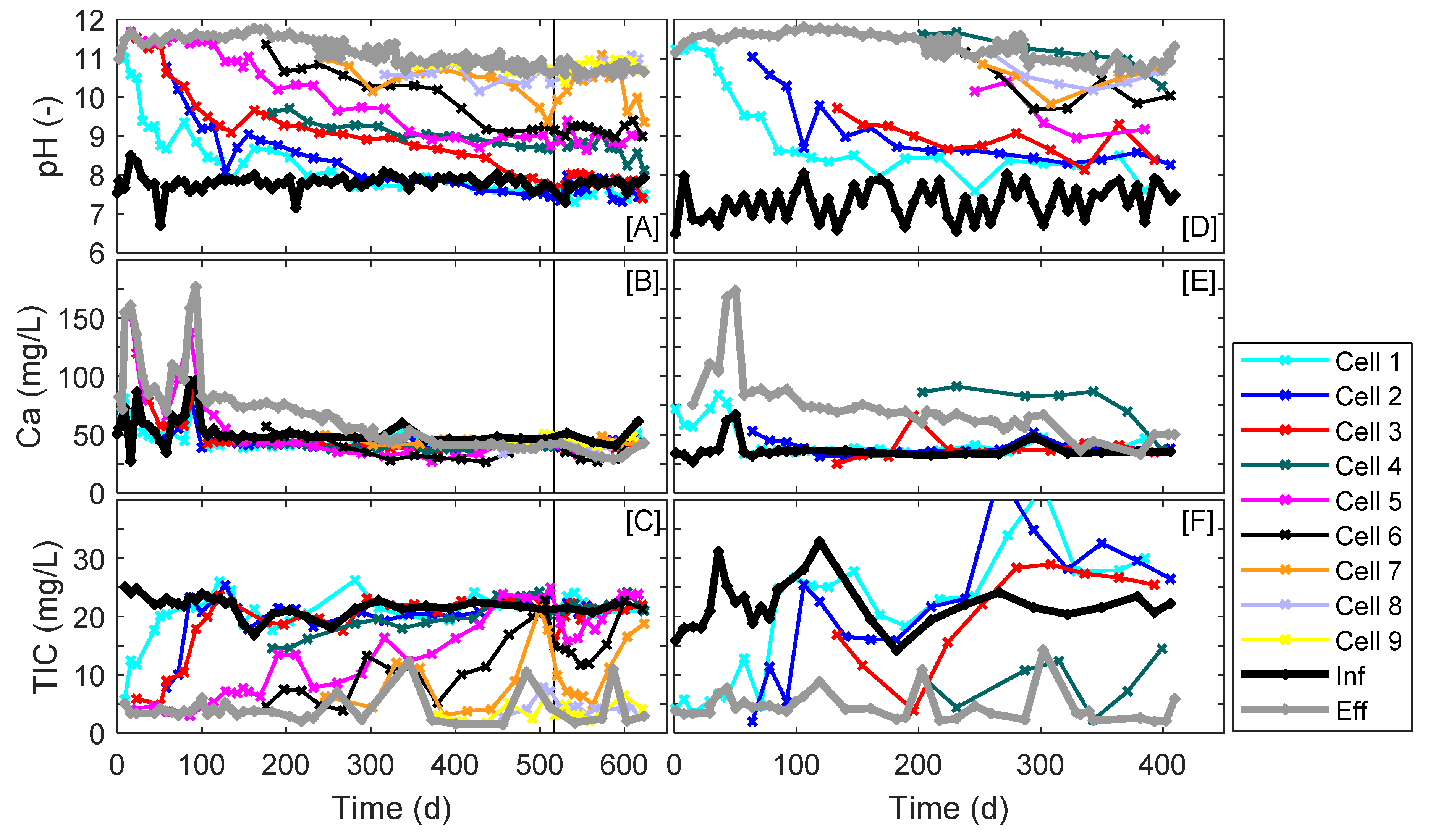
The evolution of pH, calcium, and TIC is shown in Figure 2. A progressive exhaustion of both columns was observed, as indicated by a pH drop in each cell. At the end of the experiment, complete exhaustion was reached only in cells 1 to 3 of column 1 and cell 1 of column 2, which had the same pH as the influent. The effluent pH slowly decreased from approximately 11.6 in both columns to approximately 10.5 in column 1 and 10.8 in column 2. Calcium trends can be explained by a combination of slag dissolution and precipitation of hydroxyapatite and calcite. A high effluent calcium concentration was observed at the beginning of operation due to the high slag initial reactivity. Cell 4 of column 2 had an irregular behavior compared to other cells. Its pH was between 11.0 and 11.5 and its calcium concentration was above 75 mg/L, which were higher than values observed in cells 5 to 9. Such behavior was attributed to a possible dead zone formed around the sampling valve, leading to an artificially longer contact time in this region. A negligible COD removal efficiency of 1% was observed in column 2. Such negligible COD removal can be explained by the high pH and the absence of nutrients in the influent, resulting in a low biological activity.
o-PO4 curves are not shown as they were already discussed previously [23], and phosphorus removal performance is not within the scope of the present study. Briefly, the o-PO4 concentration at the effluent of column 1 was below 0.05 mg/L for the whole duration of the experiment. The o-PO4 concentration slowly increased in cells 1 to 6 of column 1 following progressive exhaustion.
The slag dissolution and resulting high pH and high calcium concentration are favorable conditions for calcite precipitation. Crystalline calcite observed in X-ray diffractograms and low TIC concentration in cells confirmed the progressive formation of calcite within columns. An example of X-Ray diffractogram is provided in Figure S2. The TIC concentration was at first around 5 mg/L in all cells, then it slowly increased back to the influent concentration of about 20 to 30 mg/L following pH drop. TIC leaching was observed from cells 1 to 3 of column 2 after day 240.
3.2. Long-Term Loss of Effective Porosity in Steel Slag Filters Fed with Inorganic and Organic Influents
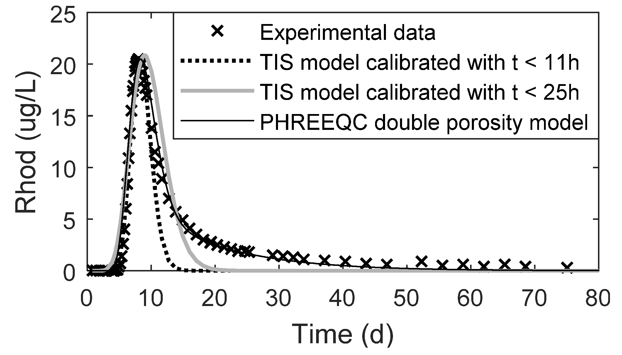
A comparison of tracer test calibration using the PHREEQC double porosity model and the TIS model is shown in Figure 3. Two TIS calibrations are presented using partial data (t ≤ 11 h or t ≤ 25 h) in the optimization step. Calibrated parameters were N = 28.2 and TRHVe = 8.5 h for TIS-11 h; N = 12.9 and TRHVe = 9.8 h for TIS-25 h; and D* = 5 cm, Dn = 5 × 10⁻⁶ s−1 and HRTVe = 9.4 h for the PHREEQC model. The PHREEQC double porosity model resulted in a better calibration than the TIS model. The TIS model can either calibrate the peak or part of the tail, depending on the number of data points considered in the optimization. Adding data to the optimization step slightly improved tail fitting, but peak fitting was shifted. The better accuracy of the PHREEQC double porosity model can be explained by its greater complexity which involves three calibration parameters for effective volume, dispersion, and retardation, compared to the TIS model which involves only two parameters for effective volume and dispersion.
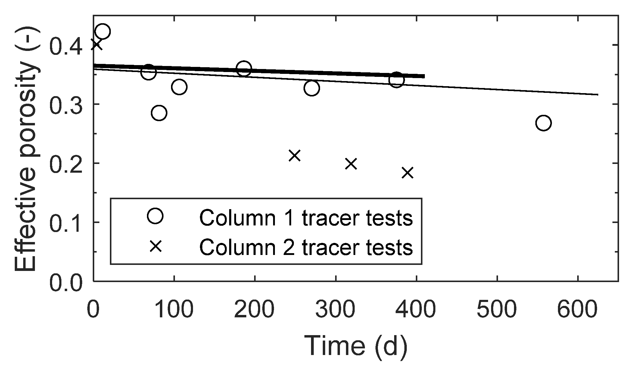
The calibrated hydraulic parameters from tracer tests are shown in Table 2. The double porosity model accurately reproduced experimental tracer breakthrough curves, as illustrated in Figures S3 and S4. The mean experimental tracer recovery was 88%. The calibrated dispersivity was between 2.8 and 10 cm, which are typical values for sand to gravel columns [30]. Dispersivity values in column 2 were higher than those of column 1, which could be attributed to the higher filling of void space in column 2, leading to enhanced dispersion (discussed in the coming section). The dispersivity D* and the exchange factor Dn did not show any trend over time. The effective porosity ne was between 0.267 and 0.422 in column 1, and between 0.184 and 0.401 in column 2. A reduction of effective porosity was observed in both columns, slight in column 1 and high in column 2. The effective porosity was significantly lower than the total porosity (0.49) in both columns, as opposed to other gravel reactors for wetlands where the effective porosity of the clean bed is assumed to be equal to the total porosity [7]. Slag media is porous and has a highly irregular shape, which results in a stagnant porosity that is not present in natural media filters. Consequently, the effective porosity of a filter made of artificial media should always be determined with tracer tests.
The reduction in effective porosity following column operation is shown in Figure 4. In this figure, the effective porosity determined by tracer tests is compared with the theoretical reduction in porosity based on the volume occupied by precipitates. Both columns had an influent with a moderate alkalinity of 100 mg CaCO3/L, resulting in a relatively low theoretical reduction of porosity caused by precipitates (0.05 over 600 d in column 1 and in 0.02 over 400 d in column 2). Experimental points from tracer tests on column 1 roughly followed this calculated porosity reduction trend. In column 2, however, the effective porosity was significantly lower than predicted. These results are supported by visual observations during the experiment. In sampling events, water flowed easily in all sampling valves of column 1, while the water flow was slow in valves of column 2, which was attributed to void clogging. The measurement of water level in column 2 was aborted due to overpressure in the column. Upon dismantling, the slag media from column 1 had the same appearance as fresh slag, while in column 2, slag was cemented in an irregular distribution, in either heavily cemented zones in red, or zones with disintegrated slag grains in black (Figure S5, Supplemental Materials). In column 2, the presence of a biofilm was suspected due to the observation of a slimy substance in the slag voids of all cells upon dismantling.
The type of influent strongly affected the evolution of clogging and effective porosity in steel slag filters. In the presence of an inorganic influent without suspended solids (column 1), the loss of effective porosity was limited to the loss of the volume occupied by crystals, meaning that the reactive volume was used efficiently. A similar clogging behavior was expected in column 2 due to a similar inorganic composition in the influent (TIC of ~22 mg/L and no suspended solids) and hostile high pH conditions for biological activity. Despite the readily biodegradability of the influent COD, the biofilm establishment and growth on slag surfaces was expected to be strongly inhibited by a high pH in the column, the absence of nutrients in the influent, and the oxygen deficiency. This low biological activity was confirmed by a negligible COD removal efficiency in the column. The loss of effective porosity in column 2 did not follow the expected behavior: the effective porosity was smaller than the porosity predicted by precipitate accumulation. This suggests that in the presence of an organic influent, the progressive formation of precipitates is not sufficient to explain all the loss in porosity; other clogging mechanisms are taking place. The loss of effective porosity in the presence of an organic influent is hypothesized to be due to the formation of biofilm and changes in the slag mineralogical composition, as discussed in the following section on clogging mechanisms.
The high porosity reduction in column 2 led to an inefficient use of the slag reactivity. In a slag filter, the pH drop is due to the combination of the slag media exhaustion and the formation of a precipitate diffusion barrier, both of which affect the OH− gradient between the slag surface and the bulk void volume [23]. Fresh slag has a saturation pH of approximately 11.1 and it decreases progressively to pH 9.5 following slag leaching, according to its exhaustion functions [23]. Therefore, measuring the saturation pH of a disturbed slag sample from an exhausted filter is a way to determine how much slag was efficiently leached during the filter lifetime.
The saturation pH of disturbed slag samples at the inlet of columns is shown in Table 3. In both columns, cells 1 and 2 were considered exhausted due to their cell pH in the range of 7.5 to 8.3 (first column of the Table). In column 1, the slag saturation pH was approximately 10.0, which is one unit lower than the saturation pH of fresh slag (11.1), meaning that slag was leached efficiently during operation. In column 2, however, the inlet of the column became exhausted even if the slag itself was still reactive, as shown by a measured saturation pH of approximately 11.0. In conclusion, clogging in the first cells of column 2 was such that slag was not contacted efficiently with water.
3.3. Clogging Mechanisms in Steel Slag Filters
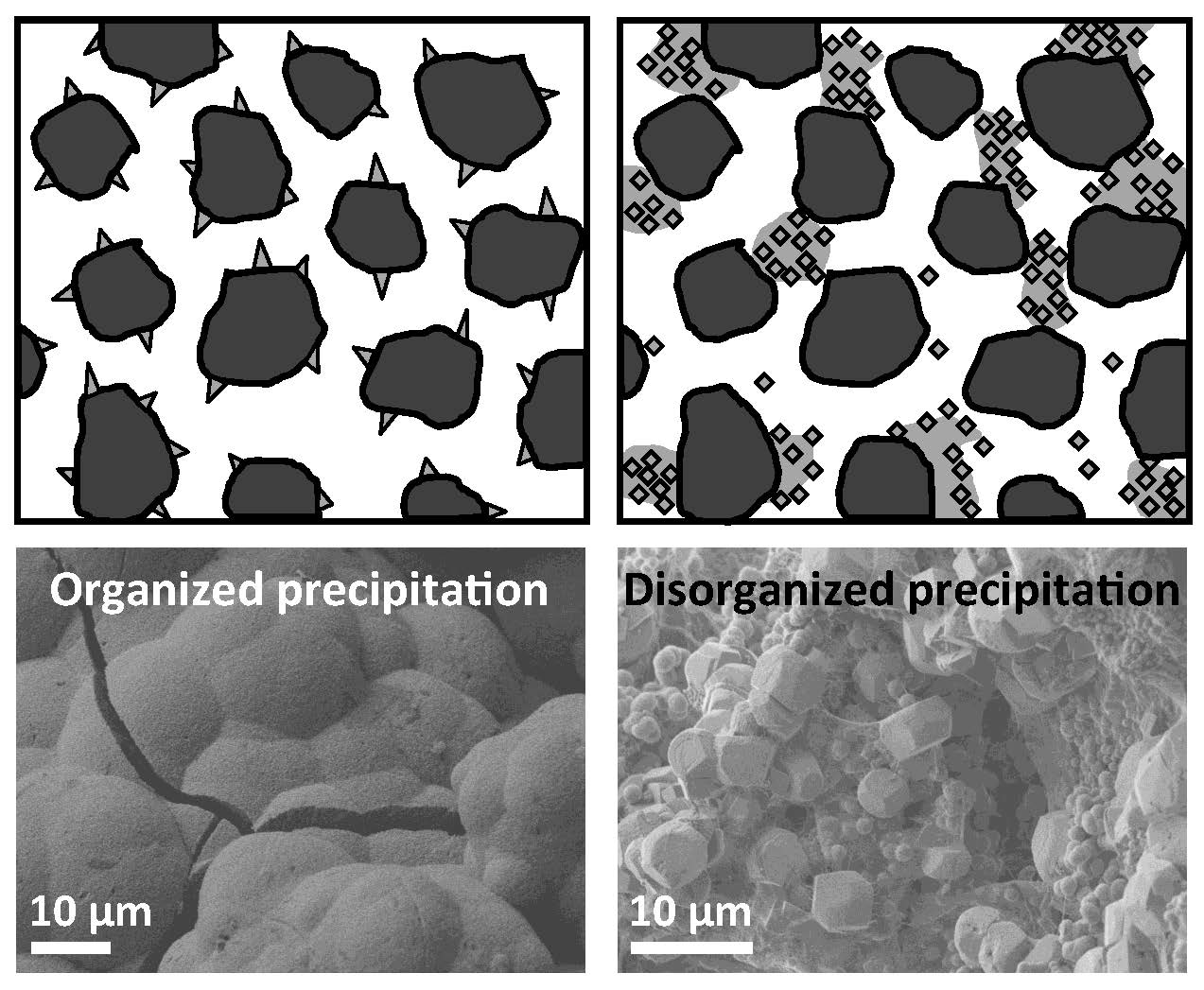
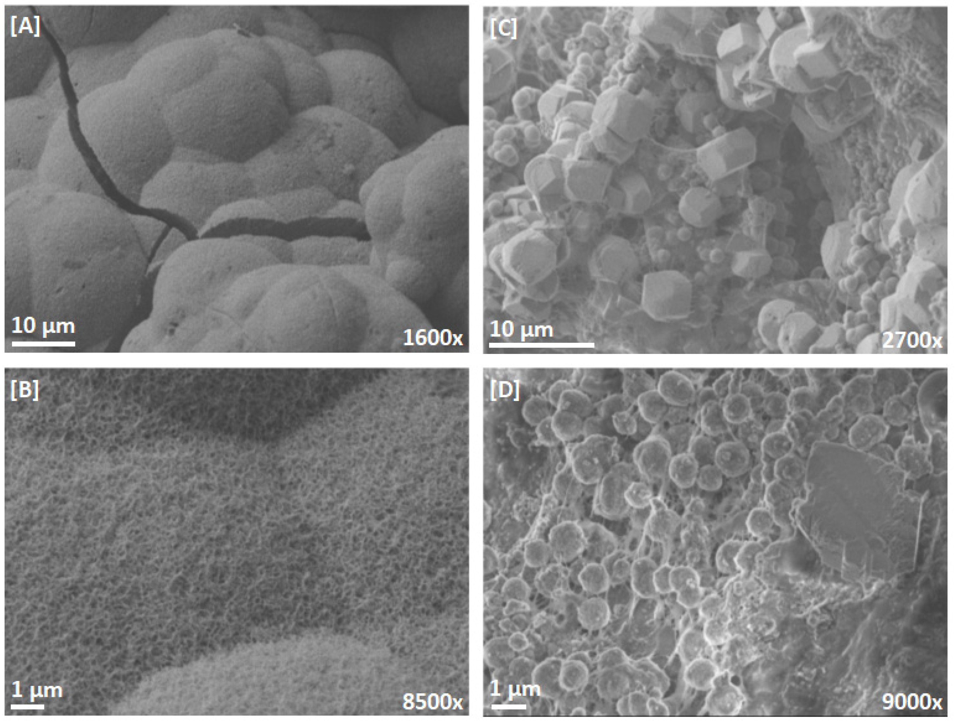
Microscopic observations of the slag surface on undisturbed slag samples after dismantling are shown in Figure 5. In column 1 (inorganic influent), numerous individual crystal seeds of size ~0.1 μm (possibly calcite and hydroxyapatite based on X-ray diffraction measurements) were clustered together in a coral-shaped network. At a larger scale, crystal structures grew according to a spherical shape of size ~30 μm. Crystals in column 1 were well organized in a dense structure with compact void occupancy, and no evidence of biological structures were seen. In column 2 (organic influent), sparse rhombohedral crystals of size ~5 μm (possibly calcite according to X-ray diffraction measurements) coexisted with ~1 μm spheres and a network of spiderweb shaped structures (possibly extracellular polymeric substances, EPS, according to their shapes). The loose crystal organization in column 2 could favor crystal detachment, potentially explaining the TIC leaching observed in cells 1 to 3 after partial exhaustion. Such TIC leaching was not observed in column 1. The presence of a biofilm in column 2 was confirmed by visual observations of a slimy substance in all cells, including cells number 6 to 9 that had a pH above 10 for the whole duration of the experiment. Despite the inhibition potential of alkaline water on bacterial growth [31] and resulting negligible COD removal, an alkali tolerant biofilm was formed in the steel slag filter over long-term operation. Such biofilm formation is possible due to the absence of wastage or backwashes over more than 400 days of operation. Alkali-tolerant microorganisms are observed in some natural waters [32] and man-made environments such as district heating systems [33].
The heterogeneous and unorganized void occupation in column 2 could explain the severe porosity loss observed. We postulate that the formation of crystals in unorganized structures results in the formation of confined voids that are not accessible for water flow, thus accelerating porosity loss. The extent of porosity reduction induced by mineral precipitation in a granular filter is influenced by the presence of biofilm on the media surface. The literature in sedimentary geology has shown that in natural environments, such as thermal springs, the precipitation of carbonate species is highly influenced by the presence of EPS [32]. EPS serve as effective calcium buffers, preventing seed crystal nucleation even in highly supersaturated conditions, leading to preferential precipitation in mucus-free area [32]. This phenomenon was observed in column 2, where crystals were dispersed in a heterogeneous distribution (Figure 5C,D). The effect of biological structures on crystal precipitation and void occupation in alkaline reactive filters has important implications as influents (agricultural runoff, wastewater) almost always contains organic matter at various concentrations. Consequently, studies using inorganic influents are not appropriate to assess the clogging behavior of alkaline reactive filters.
Future research is needed to assess the effect of organic matter and biofilm on mineralogical structures and loss of porosity under realistic scenarios.
Moreover, research is needed on bioclogging in alkaline conditions, especially regarding biokinetic growth parameters needed for estimations of bioclogging [3].
In column 2, the slag media itself might have contributed to clogging due to dissolution and reprecipitation of some compounds present in slag [21]. Iron species are sensitive to redox conditions in the influent [34]; reprecipitation or hydration of iron mineral phases may explain the severe rusty-red cementation observed in column 2.
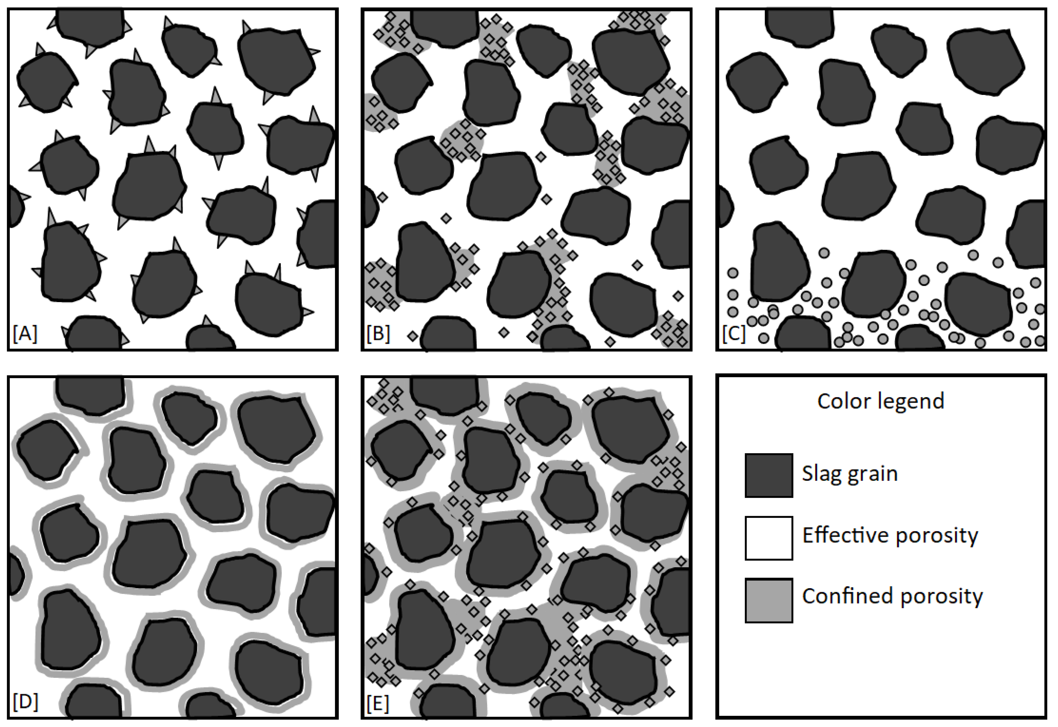
A schematic model of clogging phenomena in AGFs is shown in Figure 6. Five clogging scenarios are presented with three types of chemical clogging. First, chemical clogging with an organized structure (Figure 6A) involves compact crystals with minimal impact on the effective porosity, as observed in column 1. Second, chemical clogging with a disorganized structure (Figure 6B) involves the creation of confined voids that are not occupied by bulk crystals, but are not available for flow. Third, chemical clogging in the presence of a biofilm (Figure 6E) leads to enhanced occurrence of confined voids, as observed in column 2. The impact of the combination of chemical clogging and biofilm on the porosity loss is higher than the impact of those two separate factors. Even if the alkaline environment of an AGF is a priori unfavorable to bacterial growth, the formation of a biofilm over the long term is possible.
3.4. Effect of Clogging on Pressure Head Build-Up
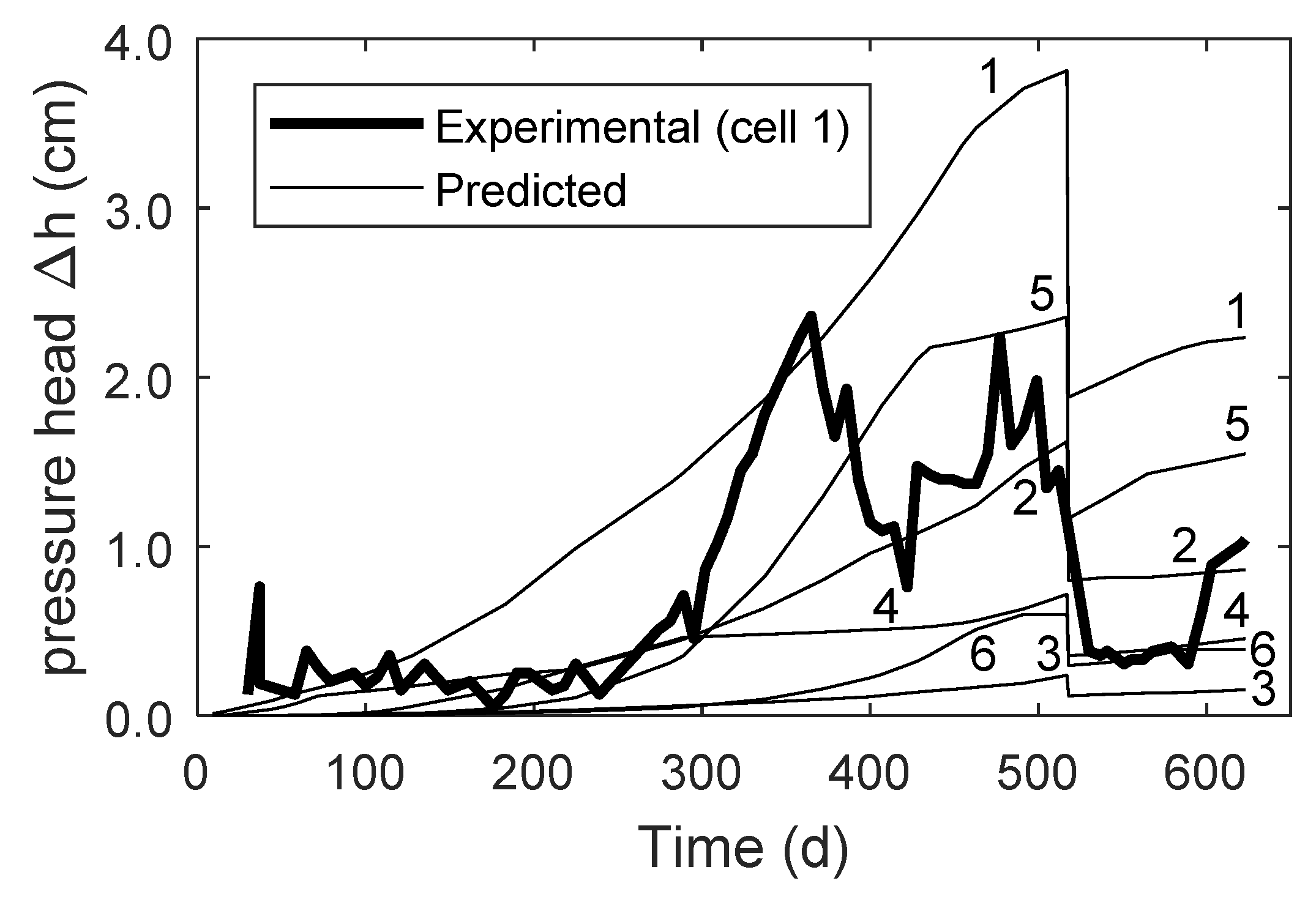
The evolution of pressure head build-up in column 1 is shown in Figure 7. The head loss in column 1 was low, below 2.5 cm for the whole duration of the experiment. The head loss was concentrated in cell 1, while no pressure buildup was observed in cells 2 to 8 (the experimental data for all cells is shown in Figure S6). The pressure head in cell 1 was irregular and it decreased when the influent flow rate was reduced. Interestingly, the pressure head increase observed at approximately 250 d in cell 1 corresponds with its complete exhaustion—its pH was the same as the influent pH. The experimental pressure head build-up is compared with predicted pressure head build-up predicted using the Kozeny–Carman relationship (Figure 7). In order to calibrate the predicted pressure head with the experimental values, the particle size of slag grains and crystal clusters used in Equation (9) were set at 7 mm and 0.028 mm, respectively.
The Kozeny–Carman relationship predicted a progressive increase of pressure head within the whole column; especially in cells 1, 5, and 2. The predicted pressure head results from the hypothesis behind many predictive equations for hydraulic conductivity: any particle in the granular media blend contributes to the hydraulic conductivity. In the case of column 1, the mass of precipitates is distributed within the whole column, with peaks in cells 1, 5, and 2 (Figure 8A). The predicted pressure head build-up in cells 2 and 5 is not observed in experimental data, a pressure increase was observed only in cell 1. This illustrates the limitations of traditional models of prediction of hydraulic conductivity of granular media used in applications with non-natural granular blends.
Three main reasons explain these limitations: 1) the Kozeny–Carman relationship is valid only for hydraulic conductivities below 1 × 10⁻⁴ m/s [35]. In that view, the Kozeny–Carman relationship is not valid in the tested column because the hydraulic conductivity was 0.1 m/s. Note that most of gravel-size man-made filters with uniform grain size are above the applicability range as well, despite the popularity of this relationship in recent works in wetland applications [3]. 2) The contribution of newly formed precipitates to the hydraulic conductivity reduction is not known. Hydraulic conductivity predictive models are based on a spherical grain assumption with size and specific surface being measured with standard methods in soil sciences and hydrogeology (sieving, sedimentometry, Atterberg limits). These methods are not applicable to the measurement of the specific surface of newly formed precipitates. The concept of particle size must be reviewed for slag filter applications because they are binary media (original media + precipitates). It is technically feasible to measure the size of individual crystals, as illustrated in Figure 8B. These nm-range measurements cannot be used as inputs to the Kozeny–Carman equations: it would calculate hydraulic conductivity in the range of 1 × 10⁻⁹ m/s or lower, which is not realistic in a gravel bed. 3) Suffossion (internal erosion or migration of fines in the porosity) criteria that are needed to properly measure the hydraulic conductivity of a noncohesive granular media [35] are not applicable in reactive filters. Newly formed precipitates or biofilm can be either cemented or unstable and transported, which can result in erratic evolution of the hydraulic conductivity. In the case of column 1, an unexplained drop of pressure head was observed at t = 350 d. Though it was not correlated with a maintenance event of piezometers or inlet pipes, such pressure head drop could be attributed to a rearrangement of precipitates within porosity following a slight hydraulic shock. Similarly, the pressure drop observed at t = 517 d should have been proportional to the drop in influent flowrate according to Darcy’s law, but it was not the case.
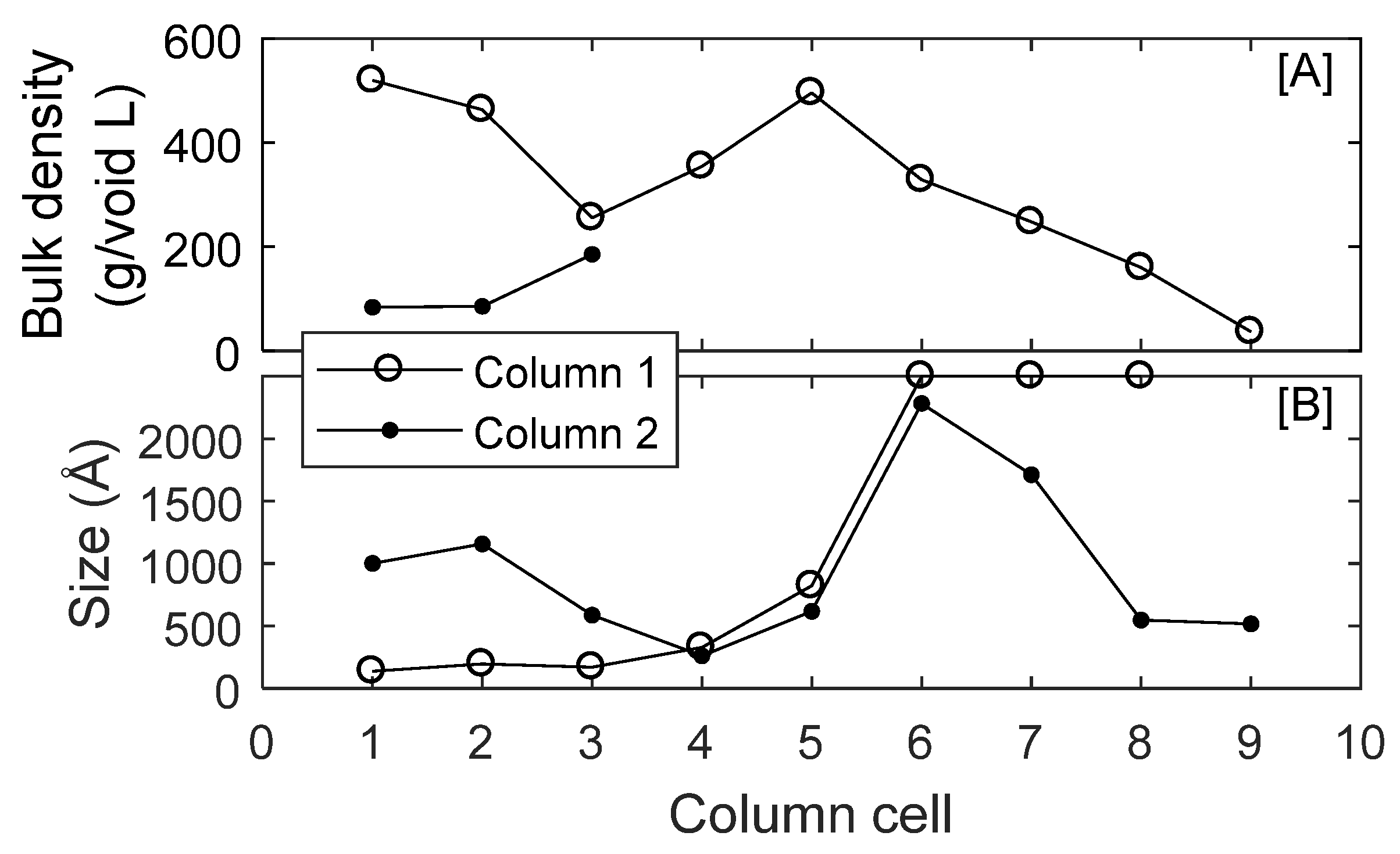
The crystal structure and connectivity are concepts that could lead to improved predictions of hydraulic conductivity in gravel-size filters with long-term filling of voids. In column 1, the mean calcite crystal size was approximately 150 Å in cells 1 to 3, and was above 2500 Å in cells 6 to 9 (Figure 8B), which suggests that different precipitation mechanisms took place in the column. The small crystal size in the inlet cells is related to the high calcite supersaturation index, which favors homogeneous precipitation (precipitation by nucleation). The preponderance of homogeneous precipitation in cells 1 to 3 was also observed for hydroxyapatite crystals, as reported previously [23]. Similarly, the large crystal sizes observed in cells 6 to 9 could be related to the prevalence of heterogeneous precipitation (precipitation by crystal growth) in low supersaturation index conditions. We postulate that homogeneous precipitation leads to a high crystal connectivity that impacts hydraulic conductivity, while heterogeneous precipitation has little impact on the crystal connectivity, because crystals grow on existing grains. Therefore, crystal aggregates that contribute to the determination of the media specific surface are small and large in the case of homogeneous and heterogeneous precipitation, respectively. The high supersaturation index that favors heterogeneous precipitation in the close inlet region might explain that a pressure head build-up was observed only in cell 1.
While column 1 showed how the supersaturation index affects the calcite crystal size and the development of pressure head in inorganic water, column 2 shows how the presence of organic matter affects the precipitation of calcite. Indeed, the calcite crystal size distribution within column (Figure 8B) does not reflect the progression from a high supersaturation index (inlet) to a low supersaturation index (outlet). However, this erratic distribution agrees with the variety and unorganized structure of crystals observed in SEM (Figure 5C,D). Crystal aggregates in column 2 certainly contributed to clogging and development of pressure head, though it was not possible to quantify pressure head build up for column 2. Overall, there is a need to develop new methods or criteria to describe crystal aggregates and their connectivity in AGFs, in both inorganic and organic water conditions. Existing methods for the measurement of specific surface in cohesive soils (correlations with Atterberg limits, BET specific surface [35]) could possibly be adapted for this purpose.
3.5. Implications for Clogging Control in Full-Scale AGFs
The results of this study highlight the importance of the inlet zone on the development of pressure head in AGFs. Consequently, future research on clogging control in full-scale AGFs should focus on precipitation mechanisms in the inlet zone and on the design of the feeding system. Factors such as size and localisation of pipes, size and localisation of holes in pipes, distribution of flow, presence of coarse-size layers or feeding regime could affect precipitation mechanisms and resulting pressure head build-up.
3.6. Implications for Alkaline Granular Filters Hydraulic Models
The findings of the manuscript regarding evolution of porosity, development of head losses, and clogging control are useful input for alkaline granular filter models, which could lead to improved design tools. Given the important effect of clogging on the loss of effective porosity, slag reactivity, and pressure head buildup, we recommend a mechanistic approach for hydraulic modelling of AGFs, using hydraulic models based on the advection-diffusion-reaction equation [28], as opposed to the TIS model [7]. Models using the advection-diffusion-reaction equation are based on intrinsic hydrogeological properties of the media (ne, D*), which allow a mechanistic approach for modelling of phenomena taking place in AGFs.
Advantages inherent to these models include first, the possible calculation of the loss of effective porosity at each iteration of the simulation based on the mass precipitated. The TIS model, however, does not offer a mechanistic approach to calculate the evolution of hydraulic parameters, even if it was successfully used to calibrate tracer tests of full-scale AGFs [13]. Indeed, there is no direct mathematical relationship between the TIS hydraulic parameters (N, HRTVe) and the porosity reduction caused by the volume occupied by precipitates.
Second, models based on the advection–diffusion–reaction equation can be adapted to predict pressure head build up in filters. Actual clogging models, however, must be improved before providing satisfactory predictions of hydraulic conductivity and pressure build up in gravel-size AGFs. First, biofilm growth kinetic constants in alkaline conditions must be assessed before being used in a clogging model [3]. Second, the results of this study showed that in a gravel-size AGFs made of steel slag, the development of pressure head is not directly related to the amount of precipitation, as illustrated by the absence of pressure head build up in the zones where precipitation was most important (column 1, cell 5, Figure 7 and Figure 8). Further research is needed to understand the impact of crystal structures on hydraulic conductivity and pressure head. Actual predictive models from particle size distribution are not suitable for AGFs.
Third, models based on the advection–diffusion–reaction equation can be complexified with useful features related to clogging. For example, the definition of new crystal structure parameters should lead to improved predictions of pressure within the filter. Crystal structure is affected by the supersaturation level [36] and by water velocity [37]. In such scenarios, the model must allow the calculation of local water velocity and local saturation index. In particular, local velocities in 2D flows subject to progressive clogging are complex [3]. The calculation of local velocities is not straightforward in models based on the TIS hypothesis.
In summary, we recommend dedicating research efforts in the development of hydraulic models for AGFs using a model based on the advection–diffusion–reaction equation. Three important upgrades are recommended:
- (1)
- evolution of porosity (affecting the available contact time),
- (2)
- evolution of hydraulic conductivity (affecting pressure build up), and
- (3)
- study of mechanisms affecting the precipitate structure (refining the first two points).
Such features are important steps towards the development of accurate reactive filter longevity prediction tools.
Supplementary Materials
The following are available online at https://www.mdpi.com/2073-4441/12/6/1517/s1, raw experimental data (rawdata.xlsx); PHREEQC functions (launch_tracertest.m and PHREEQCfct_tracer.m); Table S1: Measurement of the hydraulic conductivity of column 2 at t = −1 d using a constant head protocol, Figure S1: Precipitate sampling by washing and sedimentation in a pan, Figure S2: XRD pattern of precipitates sampled in column 2, cell 1, Figure S3: Tracer test calibration in column 1 at different times of operation (indicated at the top right corner), Figure S4: Tracer test calibration in column 2 at different times of operation (indicated at the top right corner), Figure S5: Pictures of column cross-sections at the interface between cells 2 and 3. A: column 1, showing black slag with a uniform distribution of white precipitates. B: column 2, showing irregular distribution of precipitation into zones of either black slag with few precipitation, or red slag with heavy cementation, Figure S6: Pressure head buildup in column 1. The vertical dashed line indicates the reduction of influent flowrate from 6.9 ± 1.3 mL/min to 3.4 ± 0.5 mL/min.
Author Contributions
Validation: D.C.-M. and Y.C. conceptualization, methodology, formal analysis, investigation, software, visualization, writing—original draft: D.C.-M. funding acquisition, project administration, resources, supervision, writing—review & editing: Y.C. All authors have read and agreed to the published version of the manuscript.
Funding
This research was funded by Natural Sciences and Engineering Research Council of Canada (grant number 476673-14), the MITACS Accelerate program (grant number IT09967), Bionest, ArcelorMittal, Harsco Minerals, AgroÉnergie, GHD consulting, the RAQ (Ressources aquatiques Québec) and NORDIKEau.
Acknowledgments
The authors thank Denis Bouchard, Jérôme Leroy and Manon Leduc from Polytechnique Montreal for analytical determinations. They also thank Patricia Bove, Simon Allaire, Simon Amiot, Sophie Lévesque, Xavier Lachapelle-T. and Sanaz Alizadeh for technical assistance in column monitoring and dismantling. A special thank is given to Jean-Philippe Massé and Philippe Plamondon, from Polytechnique Montreal CM2 lab for their assistance with XRD and SEM analysis. The slag material was provided by Philippe Bouchard from Harsco Minerals.
Conflicts of Interest
The authors declare no conflict of interest.
References
- Vohla, C.; Kõiv, M.; Bavor, H.J.; Chazarenc, F.; Mander, Ü. Filter materials for phosphorus removal from wastewater in treatment wetlands—A review. Ecol. Eng. 2011, 37, 70–89. [Google Scholar] [CrossRef]
- Mercado-Borrayo, B.M.; González-Chávez, J.L.; Ramírez-Zamora, R.M.; Schouwenaars, R. Valorization of Metallurgical Slag for the Treatment of Water Pollution: An Emerging Technology for Resource Conservation and Re-utilization. J. Sustain. Metall. 2018, 4, 50–67. [Google Scholar] [CrossRef]
- Nivala, J.; Knowles, P.; Dotro, G.; García, J.; Wallace, S. Clogging in subsurface-flow treatment wetlands: Measurement, modeling and management. Water Res. 2012, 46, 1625–1640. [Google Scholar] [CrossRef]
- Dunets, C.S.; Zheng, Y.; Dixon, M. Use of phosphorus-sorbing materials to remove phosphate from greenhouse wastewater. Environ. Technol. 2015, 36, 1759–1770. [Google Scholar] [CrossRef]
- Weber, D.; Drizo, A.; Twohig, E.; Bird, S.; Ross, D. Upgrading constructed wetlands phosphorus reduction from a dairy effluent using electric arc furnace steel slag filters. Water Sci. Technol. 2007, 56, 135–143. [Google Scholar] [CrossRef]
- Penn, C.; Livingston, S.; Shedekar, V.; King, K.; Williams, M. Performance of field-scale phosphorus removal structures utilizing steel slag for treatment of subsurface drainage. Water 2020, 12, 443. [Google Scholar] [CrossRef] [Green Version]
- Kadlec, R.H.; Wallace, S.D. Treatment Wetlands, 2nd ed.; CRC Press: Boca Raton, FL, USA, 2009; pp. 44–45, 180–181. [Google Scholar]
- Hussain, S.I.; Blowes, D.W.; Ptacek, C.J.; Olding, D. Phosphorus removal from lake water using basic oxygen furnace slag: System performance and characterization of reaction products. Environ. Eng. Sci. 2014, 31, 631–642. [Google Scholar] [CrossRef]
- Liira, M.; Kõiv, M.; Mander, Ü.; Mõtlep, R.; Vohla, C.; Kirsimäe, K. Active filtration of phosphorus on Ca-rich hydrated oil shale ash: Does longer retention time improve the process? Environ. Sci. Technol. 2009, 43, 3809–3814. [Google Scholar] [CrossRef]
- Bowden, L.I.; Jarvis, A.P.; Younger, P.L.; Johnson, K.L. Phosphorus removal from waste waters using basic oxygen steel slag. Environ. Sci. Technol. 2009, 43, 2476–2481. [Google Scholar] [CrossRef]
- Renman, A.; Renman, G. Long-term phosphate removal by the calcium-silicate material Polonite in wastewater filtration systems. Chemosphere 2010, 79, 659–664. [Google Scholar] [CrossRef]
- Ádám, K.; Kristine Søvik, A.; Krogstad, T. Sorption of phosphorous to Filtralite-PTM - The effect of different scales. Water Res. 2006, 40, 1143–1154. [Google Scholar] [CrossRef]
- Barca, C.; Roche, N.; Troesch, S.; Andrès, Y.; Chazarenc, F. Modelling hydrodynamics of horizontal flow steel slag filters designed to upgrade phosphorus removal in small wastewater treatment plants. J. Environ. Manage. 2018, 206, 349–356. [Google Scholar] [CrossRef] [Green Version]
- Penn, C.; Chagas, I.; Klimeski, A.; Lyngsie, G. A Review of phosphorus removal structures: How to assess and compare their performance. Water 2017, 9, 583. [Google Scholar] [CrossRef]
- Manchisi, J.; Matinde, E.; Rowson, N.A.; Simmons, M.J.H.; Simate, G.S.; Ndlovu, S.; Mwewa, B. Ironmaking and steelmaking slags as sustainable adsorbents for industrial effluents and wastewater treatment: A critical review of properties, performance, challenges and opportunities. Sustainability 2020, 12, 2118. [Google Scholar] [CrossRef] [Green Version]
- Claveau-Mallet, D.; Boutet, É.; Comeau, Y. Steel slag filter design criteria for phosphorus removal from wastewater in decentralized applications. Water Res. 2018, 143, 28–37. [Google Scholar] [CrossRef]
- Bird, S.C.; Drizo, A. EAF steel slag filters for phosphorus removal from milk parlor effluent: The effects of solids loading, alternate feeding regimes and in-series design. Water 2010, 2, 484–499. [Google Scholar] [CrossRef] [Green Version]
- Claveau-Mallet, D.; Seltani, H.; Comeau, Y. Phosphorus removal and carbon dioxide capture in a pilot conventional septic system upgraded with a sidestream steel slag filter. Water 2020, 12, 275. [Google Scholar] [CrossRef] [Green Version]
- Søvik, A.K.; Kløve, B. Phosphorus retention processes in shell sand filter systems treating municipal wastewater. Ecol. Eng. 2005, 25, 168–182. [Google Scholar] [CrossRef]
- Postila, H.; Karjalainen, S.M.; Kløve, B. Can limestone, steel slag or man-made sorption materials be used to enhance phosphate-phosphorus retention in treatment wetland for peat extraction runoff with low phosphorous concentration? Ecol. Eng. 2017, 98, 403–409. [Google Scholar] [CrossRef] [Green Version]
- De Repentigny, C.; Courcelles, B. A simplified model to predict clogging of reactive barriers. Environ. Geotech. 2014, 3, 166–177. [Google Scholar] [CrossRef]
- Samsó, R.; García, J.; Molle, P.; Forquet, N. Modelling bioclogging in variably saturated porous media and the interactions between surface/subsurface flows: Application to Constructed Wetlands. J. Environ. Manage. 2016, 165, 271–279. [Google Scholar] [CrossRef] [Green Version]
- Claveau-Mallet, D.; Courcelles, B.; Pasquier, P.; Comeau, Y. Numerical simulations with the P-Hydroslag model to predict phosphorus removal by steel slag filters. Water Res. 2017, 126, 421–432. [Google Scholar] [CrossRef] [Green Version]
- APHA; AWWA; WEF. Standard Methods for the Examination of Water and Wastewater, 22th ed.; American Public Health Association: Washington, DC, USA; American Water Works Association: Washington, DC, USA; Water Environment Federation: Washington, DC, USA, 2012. [Google Scholar]
- Cullity, B.D. Diffraction III: Real samples. In Elements of X-ray diffraction; Prentice Hall: Upper Saddle River, NJ, USA, 2001. [Google Scholar]
- Klein, C.; Dutrow, B.D.; Dwight, K.J. Manual of Mineral Science, 22th ed.; Wiley: New York, NY, USA, 2002; p. 412. [Google Scholar]
- Parkhurst, D.L.; Appelo, C.A.J. Description of input and examples for PHREEQC Version 3 - A Computer Program for Speciation, Batch-Reaction, One-Dimensional Transport, and Inverse Geochemical Calculations. Available online: https://pubs.usgs.gov/tm/06/a43/ (accessed on 25 May 2020).
- Fetter, C.W.; Boving, T.B.; Kreamer, D.K. Contaminant Hydrogeology; Prentice Hall: Upper Saddle River, NJ, USA, 1999; pp. 45–73. [Google Scholar]
- Courcelles, B.; Modaressi-Farahmand-Razavi, A.; Gouvenot, D.; Esnault-Filet, A. Influence of precipitates on hydraulic performance of permeable reactive barrier filters. Int. J. Geomech. 2011, 11, 142–151. [Google Scholar] [CrossRef]
- Domenico, P.A.; Schwartz, F.W. Physical and Chemical Hydrogeology, 2nd ed.; John Wiley & Sons: New York, NY, USA, 1998; p. 222. [Google Scholar]
- Metcalf & Eddy-AECOM; Burton, F.L.; Tchobanoglous, G.; Tsuchihashi, R. Wastewater Engineering: Treatment and Resource Recovery, 3rd ed.; McGraw-Hill Education: New York, NY, USA, 2014. [Google Scholar]
- Arp, G.; Thiel, V.; Reimer, A.; Michaelis, W.; Reitner, J. Biofilm exopolymers control microbialite formation at thermal springs discharging into the alkaline Pyramid Lake, Nevada, USA. Sediment. Geol. 1999, 126, 159–176. [Google Scholar] [CrossRef]
- Kjeldsen, K.U.; Kjellerup, B.V.; Egli, K.; Frølund, B.; Nielsen, P.H.; Ingvorsen, K. Phylogenetic and functional diversity of bacteria in biofilms from metal surfaces of an alkaline district heating system. FEMS Microbiol. Ecol. 2007, 61, 384–397. [Google Scholar] [CrossRef] [Green Version]
- De Windt, L.; Chaurand, P.; Rose, J. Kinetics of steel slag leaching: Batch tests and modeling. Waste Manag. 2011, 31, 225–235. [Google Scholar] [CrossRef] [Green Version]
- Chapuis, R.P. Predicting the saturated hydraulic conductivity of soils: A review. Bull. Eng. Geol. Environ. 2012, 71, 401–434. [Google Scholar] [CrossRef]
- Tai, C.Y.; Chen, P.-C. Nucleation, agglomeration and crystal morphology of calcium carbonate. AIChE J. 1995, 41, 68–77. [Google Scholar] [CrossRef]
- Claveau-Mallet, D.; Wallace, S.; Comeau, Y. Model of phosphorus precipitation and crystal formation in electric arc furnace steel slag filters. Environ. Sci. Technol. 2012, 46, 1465–1470. [Google Scholar] [CrossRef]
Figure 1.
Schematic of column 1, with cell numbers labelled on the column. Details of valves and piezometer are shown for cell 5.
Figure 1.
Schematic of column 1, with cell numbers labelled on the column. Details of valves and piezometer are shown for cell 5.

Figure 2.
Water composition in columns 1 (A–C) and 2 (D–F). The influent flow rate of column 1 was reduced from 6.9 ± 1.3 mL/min to 3.4 ± 0.5 mL/min at time 517 d (indicated by a vertical line). Note that calcium and TIC in column 2 were analyzed only in cells in which significant exhaustion occurred (cells 1 to 4), while the sampling frequency was higher in column 1 for modelling purposes [23].

Figure 3.
Comparison of the tank-in-series (TIS) model and the PHREEQC double porosity model used for the calibration of a typical tracer test in a 1D steel slag filter. Experimental data: tracer test in column 1 at t = 271 d. Rhod refers to the rhodamine dye tracer.
Figure 3.
Comparison of the tank-in-series (TIS) model and the PHREEQC double porosity model used for the calibration of a typical tracer test in a 1D steel slag filter. Experimental data: tracer test in column 1 at t = 271 d. Rhod refers to the rhodamine dye tracer.

Figure 4.
Reduction of effective porosity in column tests. Effective porosity determined by experimental tracer tests is indicated by marks. Experimental tracer test marks are compared with the theoretical porosity reduction predicted by calculation of volume occupied by precipitates, indicated by the descending slope of the thin line (column 1) and of the thick line (column 2).

Figure 5.
Crystal organization in steel slag filters fed with inorganic (panels (A) and (B)) and organic (panels (C) and (D)) soluble influents. Panels (A) and (B): Column 1 cell 2. Panel C: Column 2 cell 9. Panel (D): Column 2 cell 6.
Figure 5.
Crystal organization in steel slag filters fed with inorganic (panels (A) and (B)) and organic (panels (C) and (D)) soluble influents. Panels (A) and (B): Column 1 cell 2. Panel C: Column 2 cell 9. Panel (D): Column 2 cell 6.

Figure 6.
Types of clogging in steel slag filters and their effect on effective porosity. (A): Chemical precipitation with organized structure. (B): Chemical precipitation with disorganized structure, leading to the formation of confined zones. (C): Accumulation of nondegradable (inorganic or organic) suspended solids from the influent, (inlet at the bottom of the figure). (D): Formation of a biofilm on the slag grain surface. (E): Hypothesized combined effect of biofilm and disorganized crystal structure, leading to an increased formation of confined zones.

Figure 7.
Pressure head buildup in cells 1 to 6 of column 1. The cell number is indicated next to each predicted line. The sudden reduction of pressure head at t = 517 d is caused by the reduction of influent flowrate from 6.9 ± 1.3 mL/min to 3.4 ± 0.5 mL/min.
Figure 7.
Pressure head buildup in cells 1 to 6 of column 1. The cell number is indicated next to each predicted line. The sudden reduction of pressure head at t = 517 d is caused by the reduction of influent flowrate from 6.9 ± 1.3 mL/min to 3.4 ± 0.5 mL/min.

Figure 8.
Precipitate distribution within cell columns at the end of the test. Panel (A): Total precipitate mass (calcite + hydroxyapatite) accumulated in columns based on calculations using TIC and o-PO4 experimental measurements (Equation (5)). In column 2, cells 4 and 9 are not shown due to the inability to sample which resulted from clogged sample valves. Panel (B): Mean calcite crystal sized based on XRD measurements. Calcite crystal size above the limit of the Scherrer’s equation (> 2500 Å) was plotted at 2500 Å (cells 6 to 9 of column 1).


Table 1.
Description of column experiments.
| Properties | Column 1 | Column 2 | |
|---|---|---|---|
| Column geometry | |||
| Length | cm | 159 | 159 |
| Diameter | cm | 10.0 | 10.0 |
| Slag mass | kg | 24.24 | 24.46 |
| Total porosity n (calculated 1) | % | 49.2 | 48.8 |
| Testing conditions | |||
| Test duration | d | 623 | 411 |
| Influent flow rate | mL/min | 6.9 (days 0–517) 3.4 (days 517–623) | 6.4 |
| HRTv (calculated 2) | h | 14.9 (days 0–517) 30.2 (days 517–623) | 15.9 |
| Influent description | |||
| Type of influent | Inorganic (K2HPO4, KH2PO4, NaHCO3, and CaCl2 in tap water) | Organic (CH3COOH and CH3COONa in tap water) | |
| pH | - | 7.80 | 7.30 |
| Alkalinity | mg CaCO3/L | 102 | 214 |
| TIC | mg C/L | 22 | 23 |
| Ca | mg/L | 54 | 37 |
| o-PO4 | mg P/L | 8.9 | n.a. |
| COD | mg/L | n.a. | 318 |
n.a.: not applicable (not measured, assumed to be nearly zero). 1: calculated according to Equation (1); 2: calculated according to Equation (2).
Table 2.
Tracer test calibration in column experiments using the PHREEQC double porosity model.
| Column 1 | Column 2 | ||||||
|---|---|---|---|---|---|---|---|
| Time | D* | Dn | ne | Time | D* | Dn | ne |
| d | cm | s−1 | - | d | cm | s−1 | - |
| 12 | 5.5 | 1.0 × 10⁻⁵ | 0.42 | 4 | 7.0 | 1.0 × 10⁻⁵ | 0.40 |
| 69 | 5.9 | 5.0 × 10⁻⁶ | 0.35 | 249 | 10.0 | 1.3 × 10⁻⁵ | 0.21 |
| 82 | 5.0 | 5.0 × 10⁻⁶ | 0.28 | 319 | 8.0 | 1.2 × 10⁻⁵ | 0.20 |
| 107 | 5.0 | 5.0 ×1 0−6 | 0.33 | 389 | 8.0 | 1.3 × 10⁻⁵ | 0.18 |
| 187 | 5.0 | 5.0 × 10⁻⁶ | 0.36 | - | - | - | - |
| 271 | 5.0 | 5.0 × 10⁻⁶ | 0.32 | - | - | - | - |
| 376 | 4.0 | 5.0 × 10⁻⁶ | 0.34 | - | - | - | - |
| 558 | 2.8 | 4.5 × 10⁻⁶ | 0.27 | - | - | - | - |
D*—dispersivity.
Table 3.
Slag exhaustion at the end of column experiments.
| Column | Cell | pH in the Cell at the End of Operation | Saturation pH Measured on Slag Sample after Dismantling |
|---|---|---|---|
| 1 | 1 | 7.49 | 10.11 |
| 1 | 2 | 7.43 | 9.87 |
| 2 | 1 | 7.59 | 10.91 |
| 2 | 2 | 8.26 | 11.31 |
© 2020 by the authors. Licensee MDPI, Basel, Switzerland. This article is an open access article distributed under the terms and conditions of the Creative Commons Attribution (CC BY) license (http://creativecommons.org/licenses/by/4.0/).
Share and Cite
MDPI and ACS Style
Claveau-Mallet, D.; Comeau, Y. Chemical Clogging and Evolution of Head Losses in Steel Slag Filters Used for Phosphorus Removal. Water 2020, 12, 1517. https://doi.org/10.3390/w12061517
AMA Style
Claveau-Mallet D, Comeau Y. Chemical Clogging and Evolution of Head Losses in Steel Slag Filters Used for Phosphorus Removal. Water. 2020; 12(6):1517. https://doi.org/10.3390/w12061517
Chicago/Turabian StyleClaveau-Mallet, Dominique, and Yves Comeau. 2020. "Chemical Clogging and Evolution of Head Losses in Steel Slag Filters Used for Phosphorus Removal" Water 12, no. 6: 1517. https://doi.org/10.3390/w12061517
Note that from the first issue of 2016, this journal uses article numbers instead of page numbers. See further details here.